EP3146287B1 - Firearm with an improved arming member - Google Patents
Firearm with an improved arming member Download PDFInfo
- Publication number
- EP3146287B1 EP3146287B1 EP15731686.0A EP15731686A EP3146287B1 EP 3146287 B1 EP3146287 B1 EP 3146287B1 EP 15731686 A EP15731686 A EP 15731686A EP 3146287 B1 EP3146287 B1 EP 3146287B1
- Authority
- EP
- European Patent Office
- Prior art keywords
- operating body
- firing pin
- firearm
- lock
- engagement
- Prior art date
- Legal status (The legal status is an assumption and is not a legal conclusion. Google has not performed a legal analysis and makes no representation as to the accuracy of the status listed.)
- Active
Links
Images



Classifications
-
- F—MECHANICAL ENGINEERING; LIGHTING; HEATING; WEAPONS; BLASTING
- F41—WEAPONS
- F41A—FUNCTIONAL FEATURES OR DETAILS COMMON TO BOTH SMALLARMS AND ORDNANCE, e.g. CANNONS; MOUNTINGS FOR SMALLARMS OR ORDNANCE
- F41A17/00—Safety arrangements, e.g. safeties
- F41A17/64—Firing-pin safeties, i.e. means for preventing movement of slidably- mounted strikers
- F41A17/72—Firing-pin safeties, i.e. means for preventing movement of slidably- mounted strikers trigger-operated, i.e. the movement of the trigger bringing a firing-pin safety into inoperative position during the firing
-
- F—MECHANICAL ENGINEERING; LIGHTING; HEATING; WEAPONS; BLASTING
- F41—WEAPONS
- F41A—FUNCTIONAL FEATURES OR DETAILS COMMON TO BOTH SMALLARMS AND ORDNANCE, e.g. CANNONS; MOUNTINGS FOR SMALLARMS OR ORDNANCE
- F41A19/00—Firing or trigger mechanisms; Cocking mechanisms
- F41A19/06—Mechanical firing mechanisms, e.g. counterrecoil firing, recoil actuated firing mechanisms
- F41A19/10—Triggers; Trigger mountings
-
- F—MECHANICAL ENGINEERING; LIGHTING; HEATING; WEAPONS; BLASTING
- F41—WEAPONS
- F41A—FUNCTIONAL FEATURES OR DETAILS COMMON TO BOTH SMALLARMS AND ORDNANCE, e.g. CANNONS; MOUNTINGS FOR SMALLARMS OR ORDNANCE
- F41A19/00—Firing or trigger mechanisms; Cocking mechanisms
- F41A19/06—Mechanical firing mechanisms, e.g. counterrecoil firing, recoil actuated firing mechanisms
- F41A19/25—Mechanical firing mechanisms, e.g. counterrecoil firing, recoil actuated firing mechanisms having only slidably-mounted striker elements, i.e. percussion or firing pins
- F41A19/27—Mechanical firing mechanisms, e.g. counterrecoil firing, recoil actuated firing mechanisms having only slidably-mounted striker elements, i.e. percussion or firing pins the percussion or firing pin being movable relative to the breech-block
- F41A19/29—Mechanical firing mechanisms, e.g. counterrecoil firing, recoil actuated firing mechanisms having only slidably-mounted striker elements, i.e. percussion or firing pins the percussion or firing pin being movable relative to the breech-block propelled by a spring under tension
- F41A19/30—Mechanical firing mechanisms, e.g. counterrecoil firing, recoil actuated firing mechanisms having only slidably-mounted striker elements, i.e. percussion or firing pins the percussion or firing pin being movable relative to the breech-block propelled by a spring under tension in bolt-action guns
- F41A19/31—Sear arrangements therefor
- F41A19/32—Sear arrangements therefor for catching the percussion or firing pin after each shot, i.e. in single-shot or semi-automatic firing mode
Definitions
- the present invention relates to a firearm comprising a firing device.
- the firearm which the present invention relates to is a handgun; preferably, a semi-automatic handgun.
- Arming devices are known of which are suitable to be operationally connected to the firing mechanism of the firearm in such a way as to effectively perform firing going to operate directly on firing pin, and not, for example, through the hammer.
- Said known devices are generally located, at least partially, inside the firearm, preferably, in the back of the same.
- said devices are also operatively connected to a support frame in turn located, at least partially, inside the stock of the firearm.
- the frame is designed to support the arming devices and the firing mechanism of the firearm.
- Prior devices of different types exist characterised by different operating configurations having multiple mechanisms and different components composing them.
- the prior arming devices are characterised by a movement mechanism such that a movement of the trigger results in a movement by suitable transmission means, preferably, in rotation, of an arming member suitable to engage and disengage the firing pin (in some embodiments even to pre-load it) as well as to move a locking element of the firing pin to place it in a locked position or an unlocked position in which the movement of the firing pin to perform actual firing is prevented or allowed.
- One of the main requirements related to this type of device is to be as responsive as possible, and thus be as "ready to fire” as possible.
- the known devices especially those characterised by a marked pursuit of readiness to fire are flawed by a series of problems as a result of which they present a degree of risk.
- the known devices have a range of configurations in which the firearm is not in a safe configuration, but in an unsafe one i.e. a configuration in which the firing pin is free to move. If the firing pin is free to move, it may therefore happen that the firearm fires a shot, for example an accidental shot following a fall, or a plurality of shots in a burst, for example due to the translational motion typical of the firing mechanism of the firearm.
- the purpose of the present invention is to make a firearm comprising an arming device which is not subject to this problem, i.e. to provide a firearm comprising an arming device in which the possibility of the firearm finding itself in an unsafe configuration is eliminated.
- reference numeral 1 globally denotes a firearm in its entirety, preferably, a hand gun, preferably, a semi-automatic hand gun; while reference numeral 10 indicates, instead, an arming /disarming device comprised in said firearm 1.
- the firearm 1 comprises a fixed part (a stock 2) and a moving part (a slide 3), suitable to perform the movements needed to fire the firearm 1.
- the firearm 1 extends along a longitudinal axis Z-Z.
- the firearm 1 comprises a support frame 500 suitable to provide support to a firing mechanism 600 of the firearm 1, comprising a trigger 601; preferably, said frame also supports the arming/disarming device 10.
- the trigger 601 comprises a safety lever 602 which must first be rotated to allow the subsequent rotation of said trigger 601.
- said frame 500 is housed at least partially inside the firearm 1, in particular in the stock 2, preferably, completely inside the firearm 1, said trigger 601 is rotatably engaged to said frame 500.
- said support frame 500 extends in turn along said longitudinal axis Z-Z.
- the support frame 500 extends substantially near the sides of the firearm 1, especially in the rear area thereof where said arming device 10 is located.
- the frame 500 comprises a first 501 wing positioned substantially at the side of the firearm 1 suitable to cooperate and support the arming device 10.
- the frame 500 comprises two wings, said first wing 501 and a second wing 502; the two wings are positioned substantially at the sides of the firearm 1 one opposite the other and the arming/disarming device 10 engaged to both is thus supported on both sides.
- the frame 500 extends along the longitudinal axis Z-Z with a substantially U or C-shaped cross-section.
- the two wings 501 and 502 extend in height parallel to each other.
- the firearm especially its firing mechanism, comprises a firing pin 6 and a movable locking element 7 for the engagement or disengagement from said firing pin 6.
- the firing pin 6 is suitable to move along the longitudinal axis Z-Z, while the locking element 7 is moved transversely in relation thereto, preferably, vertically.
- the arming/disarming device 10 further comprises:
- the pressure on the trigger 601 results in a movement of the transmission means 50, which engage the arming member 100 which, by rotating, in turn moves the locking element 7 to lock or unlock the firing pin 6 and engage or disengage said firing pin 6.
- the locking element 7 is usually in a locked position and upon movement of the arming member 100 is moved into an unlocked position.
- said transmission means 50 comprise a transmission lever 51 with one end connected to the trigger and the other end 601 engaging the arming member 100.
- the arming member 100 comprises:
- the firing pin operating body 110 is engageable in rotation by the lock operating body 120 to in turn be moved in rotation; in the following description, the respective elements of the two components specifically designed to allow this interaction during rotation will be extensively described.
- the arming member comprises two separate components with specific and distinct roles in the firing mechanism; preferably, such components are designed to reciprocally engage as a function of their angular arrangement in the performance of their respective roles.
- the arming member 100 further comprises a support pin 200 for the rotatable support of the firing pin operating body 110 and of the lock operating body 120 to permit the mutual engagement of the components.
- the support pin 200 extends along a transversal axis X-X to the firearm 1, in which the firing pin operating body 110 and the lock operating body 120 are mounted coaxially onto the support pin 200.
- the support pin 200 extends transversely to the longitudinal axis Z-Z; where the transversal axis X-X is for example, perpendicular to the longitudinal axis Z-Z.
- the support pin 200 cooperates transversely with the firearm 1, in particular in some embodiments it cooperates with the support frame 500, e.g. with the two wings 501 and 502.
- the pin 200 is translatable along said transversal axis X-X, and the components of the arming member 100 are suitable to be fitted on it.
- the locking element 7 is kept in a locked position in which it prevents the movement of the firing pin 6, and is movable into an unlocked position which allows the movement of the firing pin 6; preferably, the locking element 7 is moved into said unlocked position by the lock operating body 120 in the phases of the firing cycle in which the transmission means 50 engage the transmission engagement element 151.
- the locking element 7 is suitable to be engaged by the lock operating body 120 for its vertical translation, depending on the transmission means, wherein said locking element 7 is kept in a lowered position, thus locking the firing pin, by special elastic pressure elements 71, such as a coil spring, insisting on the locking element 7.
- special elastic pressure elements 71 such as a coil spring
- the engagement element 151 extends laterally, for example parallel to the support pin 200, thus parallel to the transversal axis X-X, and is therefore engageable in thrust by the transmission means 50.
- the firing pin operating body 6 has the firing pin engagement element 156 and the lock operating body 120 has the lock engagement element 157, both said components extend radially relative to the support pin 200 so as to engage the firing pin 6 and the engagement element 7 located in the firearm in a position above the arming member 100.
- the firing pin engagement element 156 engages the firing pin 6, at a firing pin tooth 61, preferably, located in the rear area.
- the firing pin spring 69 is also located suitable to compress itself during the firing cycle following the engagement between the firing pin operating body and 110 and the firing pin 6.
- the transmission means 50 are placed in translation by actuating the trigger 601, identifying a predefined stroke in translation.
- the translation of the transmission means 50 is composed of a series of pre-defined strokes: a pre-stroke, a stroke and an extra-stroke.
- the pre-stroke is the translation stroke in which the transmission means 50 translate until achieving contact with the lock operating body 120, in particular with the transmission engagement element 151.
- the active stroke is the stroke in which the translation means 50 move the lock operating body 120 in rotation, as far as bringing the locking element 7 into an unlocked position and simultaneously moving the firing pin operating body 110 in rotation until it disengages from the firing pin 6.
- the extra-stroke is the stroke in which the transmission means 50 translate until the trigger 601 reaches the end of its rearward stroke.
- the extra-stroke is needed and ever-present to ensure, in any condition of dimensional tolerances of the different components, the disengagement of the firing pin 6 from the firing pin operating body 110, and in particular of the firing pin element 156.
- the sum of the active stroke and the extra-stroke is called “reset”, i.e. the minimum forward stroke which the trigger, and thus the transmission means must make to make the next shot fireable.
- the beginning of the movement of the locking element 7 upon the action of the lock operating body 120 occurs before or at the latest simultaneously with the beginning of the disengagement of the firing pin operating body 110 from the firing pin 6.
- an angular gap is preferably, present between the lock operating body 120 and the firing pin operating body such that for a first angular portion the lock operating body 120 turns on its own and then simultaneously with the firing pin operating body 110.
- said angular distance is between 0 and 4 degrees.
- the beginning of the movement of the locking element 7 corresponds concurrently with the start of the active stroke.
- the arming member 100 comprises elastic means 300 suitable to engage the firing pin operating body 110 and the lock operating body 120 to keep them respectively in predefined angular positions when not engaged by or with the respective components.
- said elastic means 300 are in turn fitted on the support pin 200 and engage the different bodies.
- the elastic means 300 comprise a torsion spring lock 320 suitable to act on in torsion on the lock operating body 120 to keep it in a position of contact with the locking element 7, i.e. to keep the lock engagement element 157 in contact with the locking element 7.
- the lock operating body 120 when engaged by the transmission means 50 is instantly ready to impress an action on the locking element 7 to move it height-wise and place it in an unlocked position, starting from the locked position which it is kept in by the elastic pressure element 71.
- the lock torsion spring 320 is a coil spring.
- the torsion spring lock 320 is housed in a sandwich between the firing pin operating body 110 and the lock operating body 120 acting with the two ends respectively on both components.
- the firing pin operating body 110 and the lock operating body 120 respectively comprise the gripping and thrust elements, which extend, preferably, parallel to the transversal axis X-X, for the mutual engagement between the firing pin operating body 110 and lock operating body 120 when placed in rotation.
- the firing pin operating body 110 comprises at least one firing pin operating body gripping and thrust element 111 and the lock operating body 120 comprises at least two lock gripping and thrust elements 121 placed angularly at the sides of the firing pin operating body gripping and thrust element 111; in a further embodiment (not shown in the drawings), it is the firing pin operating body 110 which comprises two gripping and thrust elements while the lock operating body 120 comprises one of such two.
- firing pin operating body has two angularly spaced firing pin operating body gripping and thrust elements 111
- lock operating body has two lock operating body gripping and thrust elements 121 respectively suitable to cooperate with the reciprocal elements on the firing pin operating body 110.
- the firing pin operating body gripping and thrust elements 111 and/or lock operating body gripping and thrust elements 121 extend parallel to the transversal axis X-X in opposite directions, in order to achieve the reciprocal engagement between the components.
- the firing pin operating body gripping and thrust elements 111 are the shape of cavities which extend in the direction parallel to the transversal axis X-X while the lock operating body gripping and thrust elements 121 are the shape of protruding pins, parallel to the transversal axis X-X, to be housed in said cavities and act in conjunction with the walls thereof to perform the engagement action.
- the movement commanded in rotation by the lock operating body 120 involves a mutual engagement of a lock operating body gripping and thrust element 121 with the firing pin operating body gripping and thrust element 111; upon continuation of said movement in rotation of the lock operating body 120 the firing pin operating body is also rotated by means of said engagement.
- the lock operating body gripping and thrust element 121 placed above, is suitable to perform said engagement during the rotation.
- the elastic means 300 comprise a torsion-compression spring 310 suitable to act in compression on the firing pin operating body 110 and on the lock operating body 120 to keep them in place laterally, and suitable to act in torsion on the firing pin operating body 110 to keep it in a return position, for example with the firing pin engagement element 156 raised in height, suitable to perform engagement with the firing pin 6.
- the torsion-compression spring 310 is suitable to keep the firing pin operating body 110 and the lock operating body in place laterally so as to guarantee over time the reciprocal engagement of the two components and, in particular, their position such that engagement with the firing pin 6 and the locking element 7 is guaranteed.
- the torsion-compression spring 310 acts in torsion on the firing pin operating body 110 in order to keep it in an angular position such as to maintain its engagement with the firing pin 6, so that its disengagement is only possible by acting on the trigger 601.
- the torsion -compression spring 310 is a coil spring.
- the torsion-compression spring 310 comprises a first end 311 engaging the firing pin operating body 110 and a second end 312 engaging a generic fixed element part of the firearm 1, for example the frame 500.
- the torsion-compression spring 310 has a greater elastic coefficient than the lock torsion spring 320.
- the trigger action 601 must be such as to overcome the action of the elastic pressure means 71 acting on the locking element 7, the twisting action of the torsion - compression spring 310, the action of the firing pin 69 and the generic return springs on the trigger 609.
- the arming member 100 is suitable to operate distinctly on the locking element 7 in a manner such as to command a movement thereof into an unlocked position solely by operation of the trigger 601, in detail at the end of a firing cycle since the locking element 7 is in a locked position, and thus lowered, and a new and further movement of the trigger is needed for the locking element 7 to be brought back into a new unlocked position thereby allowing the movement of the firing pin 6.
- the slide 3 and in particular the obturator comprised therein has a projecting tab 35 suitable to perform a lateral abutment along the transversal axis X-X to the firing pin operating body 110.
- the arming member 100 is movable along the transversal axis X-X. To permit the aforesaid translation, it is necessary to move the slide 3 backwards to bring the projecting tab into a retracted position along the longitudinal axis Z-Z; in said retracted position it is therefore possible to move the arming member 100 and in particular the firing pin operating body 110 which, in turn, is disengaged from the firing pin 6 by pressing the end of the pin 200.
- said operation is safe. To perform it in fact it is not necessary to operate the trigger, and, consequently, the locking element 7 is kept in the firing pin locked position so as to intercept the firing pin 6 and prevent any firing. In yet other words, in the performance of said operation, the lock operating body 120 is not rotated around the transversal axis X-X, but is translated on it.
- the firearm which the present invention relates to is characterised by the annulment of the possibility that the firearm has a degree of risk in which the involuntary firing of a shot and/or burst of shots is possible.
- the firearm according to the present invention in case of "misfire”, i.e. non-firing, with the firearm in the condition of having a shot in the barrel, once the trigger is released, has the locking element in the locked position, thereby blocking the firing pin and thus avoiding that an impact or fall could resulting in an accidental shot being fired.
- the firing pin in the case in which the firing pin, in the case of a normal firing sequence, is not intercepted by the firing pin operating body, for example due to wear or failure thereof, the firing pin is in any case locked by the action of the firing pin operating body.
- a further advantageous aspect lies in the fact that the firearm of the present invention is extremely reactive and ready for firing.
- Yet a further advantageous aspect is that it is not necessary for a first portion of the active stroke to be dedicated to moving the lock operating body towards the locking element since these are always mutually engaged; in other words, it is extremely advantageous that the lock operating body is always kept in contact with the locking element so that the movement of the latter is simultaneous to the active stroke in its entirety.
- the rotation between the lock operating body and the firing pin operating body is related to angular distances and to the positioning by designing gripping and thrust elements present on the lock operating body and on the firing pin operating body.
- the firearm according to the present invention is characterized by a very competitive and contained "reset".
- a further advantageous aspect lies in the possibility of being able to design the obturator member of a compact and contained size.
- the fact that the lock operating body is kept in contact with the locking element means its dimensions can be as contained as possible.
- the operating body is kept in a safe lateral position, thereby keeping the lock operating body and the firing pin operating body always aligned with the locking element and with the firing pin, even in the event of a side impact.
- a person skilled in the art may make variations to the embodiments of the aforesaid firearm or replace elements with others functionally equivalent so as to satisfy specific requirements.
- a solution may be provided for without a support frame, in which the components are mounted and supported directly on the frame.
Landscapes
- Engineering & Computer Science (AREA)
- General Engineering & Computer Science (AREA)
- Toys (AREA)
- Aiming, Guidance, Guns With A Light Source, Armor, Camouflage, And Targets (AREA)
Description
- The present invention relates to a firearm comprising a firing device. Preferably, the firearm which the present invention relates to is a handgun; preferably, a semi-automatic handgun.
- Arming devices are known of which are suitable to be operationally connected to the firing mechanism of the firearm in such a way as to effectively perform firing going to operate directly on firing pin, and not, for example, through the hammer.
- Said known devices are generally located, at least partially, inside the firearm, preferably, in the back of the same. Preferably, said devices are also operatively connected to a support frame in turn located, at least partially, inside the stock of the firearm. The frame is designed to support the arming devices and the firing mechanism of the firearm.
- Prior devices of different types exist characterised by different operating configurations having multiple mechanisms and different components composing them.
- The prior arming devices are characterised by a movement mechanism such that a movement of the trigger results in a movement by suitable transmission means, preferably, in rotation, of an arming member suitable to engage and disengage the firing pin (in some embodiments even to pre-load it) as well as to move a locking element of the firing pin to place it in a locked position or an unlocked position in which the movement of the firing pin to perform actual firing is prevented or allowed.
- An example of an arming member of this type is illustrated in the document
US2011/0289811 and in documentUS6865979 . - One of the main requirements related to this type of device is to be as responsive as possible, and thus be as "ready to fire" as possible.
- The known devices, especially those characterised by a marked pursuit of readiness to fire are flawed by a series of problems as a result of which they present a degree of risk. In other words the known devices have a range of configurations in which the firearm is not in a safe configuration, but in an unsafe one i.e. a configuration in which the firing pin is free to move. If the firing pin is free to move, it may therefore happen that the firearm fires a shot, for example an accidental shot following a fall, or a plurality of shots in a burst, for example due to the translational motion typical of the firing mechanism of the firearm.
- The purpose of the present invention is to make a firearm comprising an arming device which is not subject to this problem, i.e. to provide a firearm comprising an arming device in which the possibility of the firearm finding itself in an unsafe configuration is eliminated.
- Such purpose is achieved by a firearm according to
claim 1. In particular, the firearm according to the present invention resolves the problem of the prior art. - Further characteristics and advantages of the invention will be evident from the characteristics described below and claimed in the dependent claims. The characteristics and advantages of the firearm according to the present invention will be evident from the description given below, made by way of a non-limiting example, with reference to the attached drawings, wherein:
-
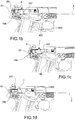
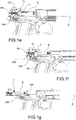
figures 1a to 1m respectively show a side view in cross-section of the rear portion of a firearm according to the present invention, during the various phases of the firing cycle, i.e. respectively in an initial configuration, a pre-stroke start configuration with the safety of the trigger pressed, a pre-stroke end and active stroke start configuration, a firing pin release configuration or i.e. end of active stroke, a firing configuration, a disconnection configuration, a retraction configuration, a reconnection configuration, a contact configuration between the locking element and the lock operating body, a return configuration to the battery, a reset configuration; -
figure 2 is a perspective view in separate parts of a part of the firearm which the present invention relates to (showing some components of the firing mechanism and the arming device); -Figure 3 shows a perspective view in separate parts of the arming member of the firearm according to the present invention, according to a first embodiment; -figures 4a and 4b show two perspective side views of the firing pin operating body comprised in the arming member as infigure 3 ; -
figures 5a and 5b show two perspective side views the lock operating body comprised in the arming member as infigure 3 ; -
figure 6 shows the support pin comprised in the arming member as infigure 3 ; -
figures 7a and 7b show the elastic means comprised in the arming member as infigure 3 . - With reference to the appended drawings,
reference numeral 1 globally denotes a firearm in its entirety, preferably, a hand gun, preferably, a semi-automatic hand gun; whilereference numeral 10 indicates, instead, an arming /disarming device comprised in saidfirearm 1. - Preferably, the
firearm 1 comprises a fixed part (a stock 2) and a moving part (a slide 3), suitable to perform the movements needed to fire thefirearm 1. Preferably, thefirearm 1 extends along a longitudinal axis Z-Z. - According to a preferred embodiment, the
firearm 1 comprises asupport frame 500 suitable to provide support to afiring mechanism 600 of thefirearm 1, comprising atrigger 601; preferably, said frame also supports the arming/disarming device 10. According to a preferred embodiment, thetrigger 601 comprises asafety lever 602 which must first be rotated to allow the subsequent rotation of saidtrigger 601. - Preferably, said
frame 500 is housed at least partially inside thefirearm 1, in particular in thestock 2, preferably, completely inside thefirearm 1, saidtrigger 601 is rotatably engaged to saidframe 500. Preferably, saidsupport frame 500 extends in turn along said longitudinal axis Z-Z. - According to a preferred embodiment, the
support frame 500 extends substantially near the sides of thefirearm 1, especially in the rear area thereof where saidarming device 10 is located. In fact, preferably, theframe 500 comprises a first 501 wing positioned substantially at the side of thefirearm 1 suitable to cooperate and support thearming device 10. According to some embodiments, theframe 500 comprises two wings, saidfirst wing 501 and asecond wing 502; the two wings are positioned substantially at the sides of thefirearm 1 one opposite the other and the arming/disarming device 10 engaged to both is thus supported on both sides. - According to said embodiments therefore the
frame 500 extends along the longitudinal axis Z-Z with a substantially U or C-shaped cross-section. Preferably, the twowings - In addition, the
firearm 1, especially its firing mechanism, comprises afiring pin 6 and amovable locking element 7 for the engagement or disengagement from saidfiring pin 6. - Preferably, the
firing pin 6 is suitable to move along the longitudinal axis Z-Z, while thelocking element 7 is moved transversely in relation thereto, preferably, vertically. - According to a preferred embodiment, the arming/
disarming device 10 further comprises: - transmission means 50 connected to the
trigger 601 and moveable by it; - an
arming member 100 comprising a plurality ofengagement elements firing pin 6 and/or thelocking element 7, - According to a preferred embodiment, in fact, the pressure on the
trigger 601 results in a movement of the transmission means 50, which engage thearming member 100 which, by rotating, in turn moves thelocking element 7 to lock or unlock thefiring pin 6 and engage or disengage said firingpin 6. In a preferred embodiment, as described below, thelocking element 7 is usually in a locked position and upon movement of thearming member 100 is moved into an unlocked position. - According to a preferred embodiment, said transmission means 50 comprise a
transmission lever 51 with one end connected to the trigger and theother end 601 engaging thearming member 100. - According to a preferred embodiment, the
arming member 100 comprises: - a firing
pin operating body 110 comprising the firingpin engagement element 156 for engagement with thefiring pin 6; - a
lock operating body 120 comprising thetransmission engagement element 151 for engagement with the transmission means 50 and thelock engagement element 157 for engagement with thelocking element 7 of thefiring pin 6. - Preferably, the firing
pin operating body 110 is engageable in rotation by thelock operating body 120 to in turn be moved in rotation; in the following description, the respective elements of the two components specifically designed to allow this interaction during rotation will be extensively described. - In other words, in said preferred embodiment, the arming member comprises two separate components with specific and distinct roles in the firing mechanism; preferably, such components are designed to reciprocally engage as a function of their angular arrangement in the performance of their respective roles.
- According to a preferred embodiment, the
arming member 100 further comprises asupport pin 200 for the rotatable support of the firingpin operating body 110 and of thelock operating body 120 to permit the mutual engagement of the components. - Preferably, the
support pin 200 extends along a transversal axis X-X to thefirearm 1, in which the firingpin operating body 110 and thelock operating body 120 are mounted coaxially onto thesupport pin 200. - In other words, the
support pin 200 extends transversely to the longitudinal axis Z-Z; where the transversal axis X-X is for example, perpendicular to the longitudinal axis Z-Z. Preferably, this way thesupport pin 200 cooperates transversely with thefirearm 1, in particular in some embodiments it cooperates with thesupport frame 500, e.g. with the twowings - According to a preferred embodiment, the
pin 200 is translatable along said transversal axis X-X, and the components of thearming member 100 are suitable to be fitted on it. - According to a preferred embodiment, the
locking element 7 is kept in a locked position in which it prevents the movement of thefiring pin 6, and is movable into an unlocked position which allows the movement of thefiring pin 6; preferably, thelocking element 7 is moved into said unlocked position by thelock operating body 120 in the phases of the firing cycle in which the transmission means 50 engage thetransmission engagement element 151. - In other words the
locking element 7 is suitable to be engaged by thelock operating body 120 for its vertical translation, depending on the transmission means, wherein saidlocking element 7 is kept in a lowered position, thus locking the firing pin, by specialelastic pressure elements 71, such as a coil spring, insisting on thelocking element 7. The thrust action on the transmission means 50, through pressure on the trigger, which induces thelock operating body 120 to rotate must overcome said action of theelastic pressure element 71. - According to a preferred embodiment, the
engagement element 151 extends laterally, for example parallel to thesupport pin 200, thus parallel to the transversal axis X-X, and is therefore engageable in thrust by the transmission means 50. - Preferably, respectively on their tops, the firing
pin operating body 6 has the firingpin engagement element 156 and thelock operating body 120 has thelock engagement element 157, both said components extend radially relative to thesupport pin 200 so as to engage thefiring pin 6 and theengagement element 7 located in the firearm in a position above thearming member 100. According to a preferred embodiment, the firingpin engagement element 156 engages thefiring pin 6, at afiring pin tooth 61, preferably, located in the rear area. - In said rear area moreover, the
firing pin spring 69 is also located suitable to compress itself during the firing cycle following the engagement between the firing pin operating body and 110 and thefiring pin 6. - According to a preferred embodiment, the transmission means 50 are placed in translation by actuating the
trigger 601, identifying a predefined stroke in translation. - Preferably, the translation of the transmission means 50 is composed of a series of pre-defined strokes: a pre-stroke, a stroke and an extra-stroke.
- In other words, the pre-stroke is the translation stroke in which the transmission means 50 translate until achieving contact with the
lock operating body 120, in particular with thetransmission engagement element 151. - The active stroke is the stroke in which the translation means 50 move the
lock operating body 120 in rotation, as far as bringing thelocking element 7 into an unlocked position and simultaneously moving the firingpin operating body 110 in rotation until it disengages from thefiring pin 6. - The extra-stroke is the stroke in which the transmission means 50 translate until the
trigger 601 reaches the end of its rearward stroke. In particular, the extra-stroke is needed and ever-present to ensure, in any condition of dimensional tolerances of the different components, the disengagement of thefiring pin 6 from the firingpin operating body 110, and in particular of thefiring pin element 156. - In addition, it is to be noted that the sum of the active stroke and the extra-stroke is called "reset", i.e. the minimum forward stroke which the trigger, and thus the transmission means must make to make the next shot fireable.
- Work on the strokes, and therefore on the size and positioning of the different components is therefore essential for making the firearm as ready as possible.
- In particular, in a preferred embodiment, the beginning of the movement of the
locking element 7 upon the action of thelock operating body 120 occurs before or at the latest simultaneously with the beginning of the disengagement of the firingpin operating body 110 from thefiring pin 6. - In other words, an angular gap is preferably, present between the
lock operating body 120 and the firing pin operating body such that for a first angular portion thelock operating body 120 turns on its own and then simultaneously with the firingpin operating body 110. Preferably, said angular distance is between 0 and 4 degrees. - In a preferred embodiment, the beginning of the movement of the
locking element 7 corresponds concurrently with the start of the active stroke. - According to a preferred embodiment, the arming
member 100 comprises elastic means 300 suitable to engage the firingpin operating body 110 and thelock operating body 120 to keep them respectively in predefined angular positions when not engaged by or with the respective components. Preferably, saidelastic means 300 are in turn fitted on thesupport pin 200 and engage the different bodies. - Preferably, in fact, the elastic means 300 comprise a
torsion spring lock 320 suitable to act on in torsion on thelock operating body 120 to keep it in a position of contact with the lockingelement 7, i.e. to keep thelock engagement element 157 in contact with the lockingelement 7. This way, thelock operating body 120, when engaged by the transmission means 50 is instantly ready to impress an action on thelocking element 7 to move it height-wise and place it in an unlocked position, starting from the locked position which it is kept in by theelastic pressure element 71. - Preferably, the
lock torsion spring 320 is a coil spring. - In particular, the
torsion spring lock 320 is housed in a sandwich between the firingpin operating body 110 and thelock operating body 120 acting with the two ends respectively on both components. - In a preferred embodiment, the firing
pin operating body 110 and thelock operating body 120 respectively comprise the gripping and thrust elements, which extend, preferably, parallel to the transversal axis X-X, for the mutual engagement between the firingpin operating body 110 and lockoperating body 120 when placed in rotation. - In other words, the firing
pin operating body 110 comprises at least one firing pin operating body gripping and thrustelement 111 and thelock operating body 120 comprises at least two lock gripping and thrustelements 121 placed angularly at the sides of the firing pin operating body gripping and thrustelement 111; in a further embodiment (not shown in the drawings), it is the firingpin operating body 110 which comprises two gripping and thrust elements while thelock operating body 120 comprises one of such two. - In further embodiments, such as those shown in the appended figures, for example
figures 4a and 4b and 5a and 5b it is to be noted how the firing pin operating body has two angularly spaced firing pin operating body gripping and thrustelements 111, and the lock operating body has two lock operating body gripping and thrustelements 121 respectively suitable to cooperate with the reciprocal elements on the firingpin operating body 110. - Preferably, therefore, the firing pin operating body gripping and thrust
elements 111 and/or lock operating body gripping and thrustelements 121 extend parallel to the transversal axis X-X in opposite directions, in order to achieve the reciprocal engagement between the components. - In the embodiment shown in the figures, the firing pin operating body gripping and thrust
elements 111 are the shape of cavities which extend in the direction parallel to the transversal axis X-X while the lock operating body gripping and thrustelements 121 are the shape of protruding pins, parallel to the transversal axis X-X, to be housed in said cavities and act in conjunction with the walls thereof to perform the engagement action. - This way, the movement commanded in rotation by the
lock operating body 120 involves a mutual engagement of a lock operating body gripping and thrustelement 121 with the firing pin operating body gripping and thrustelement 111; upon continuation of said movement in rotation of thelock operating body 120 the firing pin operating body is also rotated by means of said engagement. - Preferably, the lock operating body gripping and thrust
element 121, placed above, is suitable to perform said engagement during the rotation. - According to a preferred embodiment, the elastic means 300 comprise a torsion-
compression spring 310 suitable to act in compression on the firingpin operating body 110 and on thelock operating body 120 to keep them in place laterally, and suitable to act in torsion on the firingpin operating body 110 to keep it in a return position, for example with the firingpin engagement element 156 raised in height, suitable to perform engagement with thefiring pin 6. - In other words, the torsion-
compression spring 310 is suitable to keep the firingpin operating body 110 and the lock operating body in place laterally so as to guarantee over time the reciprocal engagement of the two components and, in particular, their position such that engagement with thefiring pin 6 and thelocking element 7 is guaranteed. - In addition, the torsion-
compression spring 310 acts in torsion on the firingpin operating body 110 in order to keep it in an angular position such as to maintain its engagement with thefiring pin 6, so that its disengagement is only possible by acting on thetrigger 601. - Preferably, the torsion -
compression spring 310 is a coil spring. - In particular, the torsion-
compression spring 310 comprises afirst end 311 engaging the firingpin operating body 110 and asecond end 312 engaging a generic fixed element part of thefirearm 1, for example theframe 500. - According to a preferred embodiment, the torsion-
compression spring 310 has a greater elastic coefficient than thelock torsion spring 320. - In other words, to achieve firing, the
trigger action 601 must be such as to overcome the action of the elastic pressure means 71 acting on thelocking element 7, the twisting action of the torsion -compression spring 310, the action of thefiring pin 69 and the generic return springs on thetrigger 609. - Taking by way of a non-limiting example
figures 1a to 1m showing a complete firing cycle, the armingmember 100 is suitable to operate distinctly on thelocking element 7 in a manner such as to command a movement thereof into an unlocked position solely by operation of thetrigger 601, in detail at the end of a firing cycle since the lockingelement 7 is in a locked position, and thus lowered, and a new and further movement of the trigger is needed for thelocking element 7 to be brought back into a new unlocked position thereby allowing the movement of thefiring pin 6. - According to a preferred embodiment, in order to keep the arming
member 100 in a lateral position along the axis X-X and in particular keep the firingpin operating body 110 and thelock operating body 120 in a lateral position on thepin 200 in such a way that these are axially aligned with the lockingelement 7 and thefiring pin 6, theslide 3 and in particular the obturator comprised therein, has a projecting tab 35 suitable to perform a lateral abutment along the transversal axis X-X to the firingpin operating body 110. - To disassemble the firearm, it is necessary to disengage the firing
pin operating body 110 from thefiring pin 6 to permit the extraction of the slide. - Typically, in the solutions typical of the prior art it is therefore necessary to pull the trigger, thereby configuring a situation of risk.
- According to a preferred embodiment, the arming
member 100 is movable along the transversal axis X-X. To permit the aforesaid translation, it is necessary to move theslide 3 backwards to bring the projecting tab into a retracted position along the longitudinal axis Z-Z; in said retracted position it is therefore possible to move the armingmember 100 and in particular the firingpin operating body 110 which, in turn, is disengaged from thefiring pin 6 by pressing the end of thepin 200. - In other words said operation is safe. To perform it in fact it is not necessary to operate the trigger, and, consequently, the locking
element 7 is kept in the firing pin locked position so as to intercept thefiring pin 6 and prevent any firing. In yet other words, in the performance of said operation, thelock operating body 120 is not rotated around the transversal axis X-X, but is translated on it. - Innovatively, the firearm which the present invention relates to is characterised by the annulment of the possibility that the firearm has a degree of risk in which the involuntary firing of a shot and/or burst of shots is possible.
- Advantageously in fact the firearm according to the present invention, in case of "misfire", i.e. non-firing, with the firearm in the condition of having a shot in the barrel, once the trigger is released, has the locking element in the locked position, thereby blocking the firing pin and thus avoiding that an impact or fall could resulting in an accidental shot being fired.
- In addition, advantageously, in the case in which the firing pin, in the case of a normal firing sequence, is not intercepted by the firing pin operating body, for example due to wear or failure thereof, the firing pin is in any case locked by the action of the firing pin operating body.
- A further advantageous aspect lies in the fact that the firearm of the present invention is extremely reactive and ready for firing.
- Yet a further advantageous aspect, is that it is not necessary for a first portion of the active stroke to be dedicated to moving the lock operating body towards the locking element since these are always mutually engaged; in other words, it is extremely advantageous that the lock operating body is always kept in contact with the locking element so that the movement of the latter is simultaneous to the active stroke in its entirety.
- Advantageously, in addition, the rotation between the lock operating body and the firing pin operating body is related to angular distances and to the positioning by designing gripping and thrust elements present on the lock operating body and on the firing pin operating body.
- In addition, advantageously the firearm according to the present invention is characterized by a very competitive and contained "reset".
- A further advantageous aspect lies in the possibility of being able to design the obturator member of a compact and contained size. For example, the fact that the lock operating body is kept in contact with the locking element means its dimensions can be as contained as possible.
- Advantageously, by means of the projecting tab the operating body is kept in a safe lateral position, thereby keeping the lock operating body and the firing pin operating body always aligned with the locking element and with the firing pin, even in the event of a side impact.
- In addition, advantageously, to disassemble the firearm no action on the trigger is needed and the firing pin locking element is kept in locked position.
- A person skilled in the art may make variations to the embodiments of the aforesaid firearm or replace elements with others functionally equivalent so as to satisfy specific requirements. For example, a solution may be provided for without a support frame, in which the components are mounted and supported directly on the frame.
- Further embodiments with different geometries of the pin, for example with special shapes or anti-rotation protuberances, may also be provided for.
- In addition, each variant described as belonging to a possible embodiment may be realised independently of the other embodiments.
Claims (15)
- Firearm (1) comprising:i) a firing mechanism (600) comprising a trigger (601), a firing pin (6), a locking element (7) suitable for being moved to lock or release the firing pin (6);ii) an arming device (10) of the firearm (1) comprising:- transmission means (50) connected to the trigger (601) and moveable by it;- an arming member (100) comprising a plurality of engagement elements (151, 156, 157) suitable for engaging the transmission means (50) and/or the firing pin (6) and/or the locking element (7), in such a way that a pressure of the trigger (601) corresponds to a movement of the transmission means (50), which, by rotating, engage the arming member (100) which in turn moves the locking element (7) to lock or release the firing pin (6) and engages or disengages said firing pin (6);
wherein the arming member (100) comprises:a) a firing pin operating body (110) comprising the firing pin engagement element (156) for engagement with the firing pin (6);b) a lock operating body (120) comprising the transmission engagement element (151) for engagement with the transmission means (50) and the lock engagement element (157) for engagement with the locking element (7) of the firing pin (6), wherein the firing pin operating body (110) is engageable in rotation by the lock operating body (120) to in turn be moved in rotation;c) a support pin (200) for the rotatable support the firing pin operating body (110) and of the lock operating body (120) to permit the mutual engagement of the components. - Firearm (1) according to claim 1, wherein the locking element (7) is kept in a locked position in which it prevents the movement of the firing pin (6), and is movable into a release position in which it permits the movement of the firing pin (6), wherein the locking element (7) is moved into said release position by the lock operating body (120) in the steps of the firing cycle in which the transmission means (50) engage the transmission engagement element (151).
- Firearm (1) according to any of the previous claims, wherein the beginning of the movement of the locking element (7) upon the action of the lock operating body (120) occurs before or at the latest simultaneously with the beginning of the disengagement of the firing pin operating body (110) from the firing pin (6).
- Firearm (1) according to any of the previous claims, wherein the engagement transmission element(151) extends laterally, for example parallel to the support pin (200), wherein the firing pin engagement element (156) and the lock engagement element (157) extend radially in relation to the support pin (200).
- Firearm (1) according to any of the previous claims, wherein the transmission means (50) are placed in translation by actuating the trigger (600), identifying a predefined stroke in translation, comprising:- a pre-stroke, in which the transmission means (50) translate until achieving contact with the lock operating body (120), in particular with the transmission engagement element (151);- an active stroke in which the translation means (50) move the lock operating body (120) in rotation, as far as bringing the locking element (7) into a release position and simultaneously moving the firing pin operating body (110) in rotation until it disengages from the firing pin (6) ;- an extra-stroke in which the transmission means (50) translate until the trigger (601) reaches the end of its rearward stroke.
- Firearm (1) according to claim 5, wherein the beginning of the movement of the locking element (7) corresponds concurrently with the start of the active stroke.
- Firearm (1) according to any of the previous claims, wherein the support pin (200) extends along a transversal axis (X-X) to the firearm (1), in which the firing pin operating body (110) and the lock operating body (120) are mounted coaxially onto the support pin (200).
- Firearm (1) according to any of the previous claims, wherein the arming member (100) comprises elastic means (300) suitable to engage the firing pin operating body (110) and the lock operating body (120) to keep them respectively in predefined angular positions when not engaged by or with the respective components.
- Firearm (1) according to claim 8, wherein the elastic means (300) comprise a torsion spring lock (320) suitable to act in torsion on the lock operating body (120) to keep it in a position of contact with the locking element (7), that is to say to keep the lock engagement element (157) in contact with the locking element (7).
- Firearm (1) according to claim 9, wherein the torsion spring lock (320) is housed in a sandwich between the firing pin operating body (110) and the lock operating body (120) acting with the two ends respectively on both components.
- Firearm (1) according to any of the previous claims, wherein firing pin operating body (110) and the lock operating body (120) respectively comprise gripping and thrust elements, which extend, preferably, parallel to the axis (X-X), for the mutual engagement of the firing pin operating body (110) and lock operating body (120) when placed in rotation.
- Firearm (1) according to claim 11, wherein the firing pin operating body (110) comprises a firing pin operating body gripping and thrust element (111) and the lock operating body (120) comprises two lock operating body gripping and thrust elements (121) placed angularly to the sides of the firing pin operating body gripping and thrust element (111), or vice versa.
- Firearm (1) according to any of the claims from 8 to 12, wherein the elastic means (300) comprise a torsion-compression spring (310) suitable to act in compression on the firing pin operating body (110) and on the lock operating body (120) to keep them in contact laterally, and suitable to act in torsion on the firing pin operating body (110) to keep it in a position of engagement with the firing pin (6).
- Firearm (1) according to claim 13, wherein the torsion-compression spring (310) has a greater elastic coefficient than the lock torsion spring (320).
- Firearm (1) according to any of the previous claims, wherein the barrel (3), preferably, the obturator, comprises a projecting fin (35) suitable to enforce a lateral abutment to the arming member (100) to keep the firing pin operating body (110) and the lock operating body (120) in a lateral position on the pin (200), in a lateral position along the transversal axis (X-X).
Applications Claiming Priority (2)
| Application Number | Priority Date | Filing Date | Title |
|---|---|---|---|
| ITBS20140102 | 2014-05-23 | ||
| PCT/IB2015/053712 WO2015177736A2 (en) | 2014-05-23 | 2015-05-20 | Firearm with an improved arming member |
Publications (2)
| Publication Number | Publication Date |
|---|---|
| EP3146287A2 EP3146287A2 (en) | 2017-03-29 |
| EP3146287B1 true EP3146287B1 (en) | 2018-03-14 |
Family
ID=52946669
Family Applications (1)
| Application Number | Title | Priority Date | Filing Date |
|---|---|---|---|
| EP15731686.0A Active EP3146287B1 (en) | 2014-05-23 | 2015-05-20 | Firearm with an improved arming member |
Country Status (5)
| Country | Link |
|---|---|
| US (1) | US9915490B2 (en) |
| EP (1) | EP3146287B1 (en) |
| BR (1) | BR112016024690B1 (en) |
| TR (1) | TR201808298T4 (en) |
| WO (1) | WO2015177736A2 (en) |
Families Citing this family (7)
| Publication number | Priority date | Publication date | Assignee | Title |
|---|---|---|---|---|
| WO2015080775A1 (en) * | 2013-09-10 | 2015-06-04 | Sturm, Ruger & Company, Inc. | Firing blocker mechanism for firearm |
| SK288609B6 (en) * | 2015-05-25 | 2018-11-05 | Grand Power, S.R.O. | Trigger mechanism of semi-automatic weapon without a hammer with direct striker and semi-automatic weapon |
| CZ2015869A3 (en) * | 2015-12-08 | 2017-02-22 | Česká Zbrojovka A.S. | A mechanism for breech capture with automatic and semiautomatic guns |
| US10175019B1 (en) * | 2017-07-10 | 2019-01-08 | Mohamed Al-Mutawa | Trigger mechanism for hammer fired-firearm |
| US10684087B2 (en) * | 2017-10-10 | 2020-06-16 | Sig Sauer, Inc. | Handgun sear with multiple engagement surfaces |
| US10156409B1 (en) * | 2017-10-26 | 2018-12-18 | Smith & Wesson Corp. | Trigger mechanism for firearm |
| WO2024069657A1 (en) * | 2022-09-26 | 2024-04-04 | Revo Arms Srl | Trigger group for a pistol and pistol comprising said trigger group |
Family Cites Families (14)
| Publication number | Priority date | Publication date | Assignee | Title |
|---|---|---|---|---|
| US1344991A (en) * | 1920-06-29 | cunningham | ||
| US2341299A (en) * | 1939-12-30 | 1944-02-08 | Remington Arms Co Inc | Firearm |
| US2341298A (en) * | 1939-12-30 | 1944-02-08 | Remington Arms Co Inc | Firearm |
| US2716923A (en) * | 1950-02-01 | 1955-09-06 | Alonzo F Gaidos | Firing mechanism for a rifle |
| US2675638A (en) * | 1951-01-06 | 1954-04-20 | Remington Arms Co Inc | Fire control for firearms |
| CH528057A (en) * | 1970-08-24 | 1972-09-15 | Sig Schweiz Industrieges | Safety device for the firing pin of handguns |
| US5050481A (en) * | 1989-12-08 | 1991-09-24 | Kniarmco Inc. | Rolling supports for trigger and firing pin assemblies in a firearm |
| BR9001880A (en) * | 1990-04-18 | 1991-11-12 | Forjas Taurus Sa | DOG DISARMING MECHANISM APPLICABLE TO SEMI-AUTOMATIC PISTOLS |
| US6865979B1 (en) * | 2001-02-07 | 2005-03-15 | Smith & Wesson Corp. | Apparatus and method for removing the slide of a semi-automatic pistol |
| US8572878B2 (en) * | 2010-05-28 | 2013-11-05 | Beretta Usa Corp. | De-cocking mechanism for striker-fired semi-automatic pistols |
| US8510980B2 (en) * | 2010-10-26 | 2013-08-20 | Apex Tactical Specialties, Inc. | Reset assist mechanism |
| US8863425B2 (en) * | 2012-06-21 | 2014-10-21 | Apex Tactical Specialties, Inc. | Firing mechanism for a firearm |
| WO2016178863A1 (en) * | 2015-05-01 | 2016-11-10 | Singh Rajpreet | Firearm with safe axis firing pin and center aligned barrel |
| SK288609B6 (en) * | 2015-05-25 | 2018-11-05 | Grand Power, S.R.O. | Trigger mechanism of semi-automatic weapon without a hammer with direct striker and semi-automatic weapon |
-
2015
- 2015-05-20 TR TR2018/08298T patent/TR201808298T4/en unknown
- 2015-05-20 WO PCT/IB2015/053712 patent/WO2015177736A2/en not_active Ceased
- 2015-05-20 EP EP15731686.0A patent/EP3146287B1/en active Active
- 2015-05-20 BR BR112016024690-0A patent/BR112016024690B1/en active IP Right Grant
- 2015-05-20 US US15/306,853 patent/US9915490B2/en active Active
Also Published As
| Publication number | Publication date |
|---|---|
| US9915490B2 (en) | 2018-03-13 |
| EP3146287A2 (en) | 2017-03-29 |
| TR201808298T4 (en) | 2018-07-23 |
| WO2015177736A2 (en) | 2015-11-26 |
| BR112016024690B1 (en) | 2022-04-19 |
| WO2015177736A3 (en) | 2016-05-06 |
| US20170059266A1 (en) | 2017-03-02 |
| BR112016024690A2 (en) | 2017-08-15 |
Similar Documents
| Publication | Publication Date | Title |
|---|---|---|
| US9915490B2 (en) | Firearm with an improved arming member | |
| US9021730B2 (en) | Firearm comprising a slide-stock locking bolt | |
| US10480882B2 (en) | Trigger group for semi-automatic firearms | |
| EP3040672B1 (en) | Interchangeable trigger assembly for firearms | |
| US10234225B2 (en) | Multiple mode disconnector for pistols | |
| US10254067B2 (en) | Trigger-locking apparatus, system, and method for semiautomatic firearms | |
| EP3367040B1 (en) | Pistol | |
| US8528241B2 (en) | Trigger mechanism for a firearm | |
| EP2541186A1 (en) | Interchangeable trigger assembly for firearms | |
| US20120090213A1 (en) | Drop-Safety Mechanism For A Firearm | |
| US10436535B1 (en) | Auto sear such as for use with any AR10 M16 or other midsize firearm platform | |
| JP6362071B2 (en) | Bolt assembly with improved rotary lockhead | |
| US8464456B2 (en) | Cocking and uncocking mechanism for a firearm | |
| US3380341A (en) | Safing means for high rate of fire multi-barrel automatic weapon | |
| US3774500A (en) | Machine pistol | |
| US12345488B2 (en) | Self-loading pistol with a pre-cocked firing pin with an assembly for safe disassembling | |
| US1433945A (en) | Gun mechanism | |
| US5726376A (en) | Breechblock system for a gun | |
| US2245621A (en) | Firing mechanism | |
| US20170160033A1 (en) | Gun Lock and Firearm Having Such a Gun Lock | |
| CA2007043C (en) | "automatic safety device for fire arms" | |
| US2945422A (en) | Firearm | |
| EP3891460B1 (en) | Firing pin safety of a bolt of a firearm | |
| US3938423A (en) | Recoil operated firearm with unitary barrel and breech bolt lock member | |
| DE2252204C3 (en) | Firearm with external, pivotable hammer |
Legal Events
| Date | Code | Title | Description |
|---|---|---|---|
| PUAI | Public reference made under article 153(3) epc to a published international application that has entered the european phase |
Free format text: ORIGINAL CODE: 0009012 |
|
| 17P | Request for examination filed |
Effective date: 20161007 |
|
| AK | Designated contracting states |
Kind code of ref document: A2 Designated state(s): AL AT BE BG CH CY CZ DE DK EE ES FI FR GB GR HR HU IE IS IT LI LT LU LV MC MK MT NL NO PL PT RO RS SE SI SK SM TR |
|
| AX | Request for extension of the european patent |
Extension state: BA ME |
|
| DAV | Request for validation of the european patent (deleted) | ||
| DAX | Request for extension of the european patent (deleted) | ||
| GRAP | Despatch of communication of intention to grant a patent |
Free format text: ORIGINAL CODE: EPIDOSNIGR1 |
|
| INTG | Intention to grant announced |
Effective date: 20171123 |
|
| GRAS | Grant fee paid |
Free format text: ORIGINAL CODE: EPIDOSNIGR3 |
|
| GRAA | (expected) grant |
Free format text: ORIGINAL CODE: 0009210 |
|
| AK | Designated contracting states |
Kind code of ref document: B1 Designated state(s): AL AT BE BG CH CY CZ DE DK EE ES FI FR GB GR HR HU IE IS IT LI LT LU LV MC MK MT NL NO PL PT RO RS SE SI SK SM TR |
|
| REG | Reference to a national code |
Ref country code: GB Ref legal event code: FG4D |
|
| REG | Reference to a national code |
Ref country code: CH Ref legal event code: EP Ref country code: AT Ref legal event code: REF Ref document number: 979312 Country of ref document: AT Kind code of ref document: T Effective date: 20180315 |
|
| REG | Reference to a national code |
Ref country code: IE Ref legal event code: FG4D |
|
| REG | Reference to a national code |
Ref country code: DE Ref legal event code: R096 Ref document number: 602015008888 Country of ref document: DE |
|
| REG | Reference to a national code |
Ref country code: NL Ref legal event code: MP Effective date: 20180314 |
|
| REG | Reference to a national code |
Ref country code: LT Ref legal event code: MG4D |
|
| PG25 | Lapsed in a contracting state [announced via postgrant information from national office to epo] |
Ref country code: HR Free format text: LAPSE BECAUSE OF FAILURE TO SUBMIT A TRANSLATION OF THE DESCRIPTION OR TO PAY THE FEE WITHIN THE PRESCRIBED TIME-LIMIT Effective date: 20180314 Ref country code: LT Free format text: LAPSE BECAUSE OF FAILURE TO SUBMIT A TRANSLATION OF THE DESCRIPTION OR TO PAY THE FEE WITHIN THE PRESCRIBED TIME-LIMIT Effective date: 20180314 Ref country code: CY Free format text: LAPSE BECAUSE OF FAILURE TO SUBMIT A TRANSLATION OF THE DESCRIPTION OR TO PAY THE FEE WITHIN THE PRESCRIBED TIME-LIMIT Effective date: 20180314 Ref country code: FI Free format text: LAPSE BECAUSE OF FAILURE TO SUBMIT A TRANSLATION OF THE DESCRIPTION OR TO PAY THE FEE WITHIN THE PRESCRIBED TIME-LIMIT Effective date: 20180314 Ref country code: NO Free format text: LAPSE BECAUSE OF FAILURE TO SUBMIT A TRANSLATION OF THE DESCRIPTION OR TO PAY THE FEE WITHIN THE PRESCRIBED TIME-LIMIT Effective date: 20180614 |
|
| PG25 | Lapsed in a contracting state [announced via postgrant information from national office to epo] |
Ref country code: BG Free format text: LAPSE BECAUSE OF FAILURE TO SUBMIT A TRANSLATION OF THE DESCRIPTION OR TO PAY THE FEE WITHIN THE PRESCRIBED TIME-LIMIT Effective date: 20180614 Ref country code: GR Free format text: LAPSE BECAUSE OF FAILURE TO SUBMIT A TRANSLATION OF THE DESCRIPTION OR TO PAY THE FEE WITHIN THE PRESCRIBED TIME-LIMIT Effective date: 20180615 Ref country code: RS Free format text: LAPSE BECAUSE OF FAILURE TO SUBMIT A TRANSLATION OF THE DESCRIPTION OR TO PAY THE FEE WITHIN THE PRESCRIBED TIME-LIMIT Effective date: 20180314 Ref country code: SE Free format text: LAPSE BECAUSE OF FAILURE TO SUBMIT A TRANSLATION OF THE DESCRIPTION OR TO PAY THE FEE WITHIN THE PRESCRIBED TIME-LIMIT Effective date: 20180314 Ref country code: LV Free format text: LAPSE BECAUSE OF FAILURE TO SUBMIT A TRANSLATION OF THE DESCRIPTION OR TO PAY THE FEE WITHIN THE PRESCRIBED TIME-LIMIT Effective date: 20180314 |
|
| PG25 | Lapsed in a contracting state [announced via postgrant information from national office to epo] |
Ref country code: AL Free format text: LAPSE BECAUSE OF FAILURE TO SUBMIT A TRANSLATION OF THE DESCRIPTION OR TO PAY THE FEE WITHIN THE PRESCRIBED TIME-LIMIT Effective date: 20180314 Ref country code: RO Free format text: LAPSE BECAUSE OF FAILURE TO SUBMIT A TRANSLATION OF THE DESCRIPTION OR TO PAY THE FEE WITHIN THE PRESCRIBED TIME-LIMIT Effective date: 20180314 Ref country code: ES Free format text: LAPSE BECAUSE OF FAILURE TO SUBMIT A TRANSLATION OF THE DESCRIPTION OR TO PAY THE FEE WITHIN THE PRESCRIBED TIME-LIMIT Effective date: 20180314 Ref country code: EE Free format text: LAPSE BECAUSE OF FAILURE TO SUBMIT A TRANSLATION OF THE DESCRIPTION OR TO PAY THE FEE WITHIN THE PRESCRIBED TIME-LIMIT Effective date: 20180314 Ref country code: PL Free format text: LAPSE BECAUSE OF FAILURE TO SUBMIT A TRANSLATION OF THE DESCRIPTION OR TO PAY THE FEE WITHIN THE PRESCRIBED TIME-LIMIT Effective date: 20180314 Ref country code: NL Free format text: LAPSE BECAUSE OF FAILURE TO SUBMIT A TRANSLATION OF THE DESCRIPTION OR TO PAY THE FEE WITHIN THE PRESCRIBED TIME-LIMIT Effective date: 20180314 |
|
| PG25 | Lapsed in a contracting state [announced via postgrant information from national office to epo] |
Ref country code: SM Free format text: LAPSE BECAUSE OF FAILURE TO SUBMIT A TRANSLATION OF THE DESCRIPTION OR TO PAY THE FEE WITHIN THE PRESCRIBED TIME-LIMIT Effective date: 20180314 Ref country code: SK Free format text: LAPSE BECAUSE OF FAILURE TO SUBMIT A TRANSLATION OF THE DESCRIPTION OR TO PAY THE FEE WITHIN THE PRESCRIBED TIME-LIMIT Effective date: 20180314 |
|
| REG | Reference to a national code |
Ref country code: CH Ref legal event code: PL |
|
| REG | Reference to a national code |
Ref country code: DE Ref legal event code: R097 Ref document number: 602015008888 Country of ref document: DE |
|
| PG25 | Lapsed in a contracting state [announced via postgrant information from national office to epo] |
Ref country code: PT Free format text: LAPSE BECAUSE OF FAILURE TO SUBMIT A TRANSLATION OF THE DESCRIPTION OR TO PAY THE FEE WITHIN THE PRESCRIBED TIME-LIMIT Effective date: 20180716 |
|
| PLBE | No opposition filed within time limit |
Free format text: ORIGINAL CODE: 0009261 |
|
| STAA | Information on the status of an ep patent application or granted ep patent |
Free format text: STATUS: NO OPPOSITION FILED WITHIN TIME LIMIT |
|
| PG25 | Lapsed in a contracting state [announced via postgrant information from national office to epo] |
Ref country code: MC Free format text: LAPSE BECAUSE OF FAILURE TO SUBMIT A TRANSLATION OF THE DESCRIPTION OR TO PAY THE FEE WITHIN THE PRESCRIBED TIME-LIMIT Effective date: 20180314 Ref country code: DK Free format text: LAPSE BECAUSE OF FAILURE TO SUBMIT A TRANSLATION OF THE DESCRIPTION OR TO PAY THE FEE WITHIN THE PRESCRIBED TIME-LIMIT Effective date: 20180314 |
|
| 26N | No opposition filed |
Effective date: 20181217 |
|
| REG | Reference to a national code |
Ref country code: IE Ref legal event code: MM4A |
|
| PG25 | Lapsed in a contracting state [announced via postgrant information from national office to epo] |
Ref country code: CH Free format text: LAPSE BECAUSE OF NON-PAYMENT OF DUE FEES Effective date: 20180531 Ref country code: SI Free format text: LAPSE BECAUSE OF FAILURE TO SUBMIT A TRANSLATION OF THE DESCRIPTION OR TO PAY THE FEE WITHIN THE PRESCRIBED TIME-LIMIT Effective date: 20180314 Ref country code: LI Free format text: LAPSE BECAUSE OF NON-PAYMENT OF DUE FEES Effective date: 20180531 |
|
| PG25 | Lapsed in a contracting state [announced via postgrant information from national office to epo] |
Ref country code: LU Free format text: LAPSE BECAUSE OF NON-PAYMENT OF DUE FEES Effective date: 20180520 |
|
| PG25 | Lapsed in a contracting state [announced via postgrant information from national office to epo] |
Ref country code: FR Free format text: LAPSE BECAUSE OF NON-PAYMENT OF DUE FEES Effective date: 20180531 Ref country code: IE Free format text: LAPSE BECAUSE OF NON-PAYMENT OF DUE FEES Effective date: 20180520 |
|
| GBPC | Gb: european patent ceased through non-payment of renewal fee |
Effective date: 20190520 |
|
| PG25 | Lapsed in a contracting state [announced via postgrant information from national office to epo] |
Ref country code: MT Free format text: LAPSE BECAUSE OF NON-PAYMENT OF DUE FEES Effective date: 20180520 |
|
| PG25 | Lapsed in a contracting state [announced via postgrant information from national office to epo] |
Ref country code: GB Free format text: LAPSE BECAUSE OF NON-PAYMENT OF DUE FEES Effective date: 20190520 |
|
| REG | Reference to a national code |
Ref country code: AT Ref legal event code: UEP Ref document number: 979312 Country of ref document: AT Kind code of ref document: T Effective date: 20180314 |
|
| PG25 | Lapsed in a contracting state [announced via postgrant information from national office to epo] |
Ref country code: HU Free format text: LAPSE BECAUSE OF FAILURE TO SUBMIT A TRANSLATION OF THE DESCRIPTION OR TO PAY THE FEE WITHIN THE PRESCRIBED TIME-LIMIT; INVALID AB INITIO Effective date: 20150520 Ref country code: MK Free format text: LAPSE BECAUSE OF NON-PAYMENT OF DUE FEES Effective date: 20180314 |
|
| PG25 | Lapsed in a contracting state [announced via postgrant information from national office to epo] |
Ref country code: IS Free format text: LAPSE BECAUSE OF FAILURE TO SUBMIT A TRANSLATION OF THE DESCRIPTION OR TO PAY THE FEE WITHIN THE PRESCRIBED TIME-LIMIT Effective date: 20180714 |
|
| P01 | Opt-out of the competence of the unified patent court (upc) registered |
Effective date: 20230522 |
|
| PGFP | Annual fee paid to national office [announced via postgrant information from national office to epo] |
Ref country code: IT Payment date: 20250325 Year of fee payment: 11 |
|
| PGFP | Annual fee paid to national office [announced via postgrant information from national office to epo] |
Ref country code: DE Payment date: 20250523 Year of fee payment: 11 |
|
| PGFP | Annual fee paid to national office [announced via postgrant information from national office to epo] |
Ref country code: BE Payment date: 20250521 Year of fee payment: 11 |
|
| PGFP | Annual fee paid to national office [announced via postgrant information from national office to epo] |
Ref country code: AT Payment date: 20250520 Year of fee payment: 11 |
|
| PGFP | Annual fee paid to national office [announced via postgrant information from national office to epo] |
Ref country code: TR Payment date: 20250512 Year of fee payment: 11 |
|
| PGFP | Annual fee paid to national office [announced via postgrant information from national office to epo] |
Ref country code: CZ Payment date: 20250409 Year of fee payment: 11 |