EP3146259B1 - Luminaire - Google Patents
Luminaire Download PDFInfo
- Publication number
- EP3146259B1 EP3146259B1 EP15796793.6A EP15796793A EP3146259B1 EP 3146259 B1 EP3146259 B1 EP 3146259B1 EP 15796793 A EP15796793 A EP 15796793A EP 3146259 B1 EP3146259 B1 EP 3146259B1
- Authority
- EP
- European Patent Office
- Prior art keywords
- luminaire
- view
- light rail
- support
- bracket
- Prior art date
- Legal status (The legal status is an assumption and is not a legal conclusion. Google has not performed a legal analysis and makes no representation as to the accuracy of the status listed.)
- Not-in-force
Links
Images
















Classifications
-
- F—MECHANICAL ENGINEERING; LIGHTING; HEATING; WEAPONS; BLASTING
- F21—LIGHTING
- F21V—FUNCTIONAL FEATURES OR DETAILS OF LIGHTING DEVICES OR SYSTEMS THEREOF; STRUCTURAL COMBINATIONS OF LIGHTING DEVICES WITH OTHER ARTICLES, NOT OTHERWISE PROVIDED FOR
- F21V5/00—Refractors for light sources
- F21V5/02—Refractors for light sources of prismatic shape
-
- F—MECHANICAL ENGINEERING; LIGHTING; HEATING; WEAPONS; BLASTING
- F21—LIGHTING
- F21S—NON-PORTABLE LIGHTING DEVICES; SYSTEMS THEREOF; VEHICLE LIGHTING DEVICES SPECIALLY ADAPTED FOR VEHICLE EXTERIORS
- F21S8/00—Lighting devices intended for fixed installation
- F21S8/04—Lighting devices intended for fixed installation intended only for mounting on a ceiling or the like overhead structures
- F21S8/06—Lighting devices intended for fixed installation intended only for mounting on a ceiling or the like overhead structures by suspension
- F21S8/061—Lighting devices intended for fixed installation intended only for mounting on a ceiling or the like overhead structures by suspension with a non-rigid pendant, i.e. a cable, wire or chain
-
- F—MECHANICAL ENGINEERING; LIGHTING; HEATING; WEAPONS; BLASTING
- F21—LIGHTING
- F21V—FUNCTIONAL FEATURES OR DETAILS OF LIGHTING DEVICES OR SYSTEMS THEREOF; STRUCTURAL COMBINATIONS OF LIGHTING DEVICES WITH OTHER ARTICLES, NOT OTHERWISE PROVIDED FOR
- F21V15/00—Protecting lighting devices from damage
- F21V15/01—Housings, e.g. material or assembling of housing parts
- F21V15/015—Devices for covering joints between adjacent lighting devices; End coverings
-
- F—MECHANICAL ENGINEERING; LIGHTING; HEATING; WEAPONS; BLASTING
- F21—LIGHTING
- F21V—FUNCTIONAL FEATURES OR DETAILS OF LIGHTING DEVICES OR SYSTEMS THEREOF; STRUCTURAL COMBINATIONS OF LIGHTING DEVICES WITH OTHER ARTICLES, NOT OTHERWISE PROVIDED FOR
- F21V17/00—Fastening of component parts of lighting devices, e.g. shades, globes, refractors, reflectors, filters, screens, grids or protective cages
-
- F—MECHANICAL ENGINEERING; LIGHTING; HEATING; WEAPONS; BLASTING
- F21—LIGHTING
- F21V—FUNCTIONAL FEATURES OR DETAILS OF LIGHTING DEVICES OR SYSTEMS THEREOF; STRUCTURAL COMBINATIONS OF LIGHTING DEVICES WITH OTHER ARTICLES, NOT OTHERWISE PROVIDED FOR
- F21V21/00—Supporting, suspending, or attaching arrangements for lighting devices; Hand grips
- F21V21/005—Supporting, suspending, or attaching arrangements for lighting devices; Hand grips for several lighting devices in an end-to-end arrangement, i.e. light tracks
-
- F—MECHANICAL ENGINEERING; LIGHTING; HEATING; WEAPONS; BLASTING
- F21—LIGHTING
- F21V—FUNCTIONAL FEATURES OR DETAILS OF LIGHTING DEVICES OR SYSTEMS THEREOF; STRUCTURAL COMBINATIONS OF LIGHTING DEVICES WITH OTHER ARTICLES, NOT OTHERWISE PROVIDED FOR
- F21V21/00—Supporting, suspending, or attaching arrangements for lighting devices; Hand grips
- F21V21/008—Suspending from a cable or suspension line
-
- F—MECHANICAL ENGINEERING; LIGHTING; HEATING; WEAPONS; BLASTING
- F21—LIGHTING
- F21V—FUNCTIONAL FEATURES OR DETAILS OF LIGHTING DEVICES OR SYSTEMS THEREOF; STRUCTURAL COMBINATIONS OF LIGHTING DEVICES WITH OTHER ARTICLES, NOT OTHERWISE PROVIDED FOR
- F21V21/00—Supporting, suspending, or attaching arrangements for lighting devices; Hand grips
- F21V21/10—Pendants, arms, or standards; Fixing lighting devices to pendants, arms, or standards
- F21V21/112—Fixing lighting devices to pendants
-
- F—MECHANICAL ENGINEERING; LIGHTING; HEATING; WEAPONS; BLASTING
- F21—LIGHTING
- F21V—FUNCTIONAL FEATURES OR DETAILS OF LIGHTING DEVICES OR SYSTEMS THEREOF; STRUCTURAL COMBINATIONS OF LIGHTING DEVICES WITH OTHER ARTICLES, NOT OTHERWISE PROVIDED FOR
- F21V23/00—Arrangement of electric circuit elements in or on lighting devices
- F21V23/04—Arrangement of electric circuit elements in or on lighting devices the elements being switches
- F21V23/0442—Arrangement of electric circuit elements in or on lighting devices the elements being switches activated by means of a sensor, e.g. motion or photodetectors
-
- F—MECHANICAL ENGINEERING; LIGHTING; HEATING; WEAPONS; BLASTING
- F21—LIGHTING
- F21V—FUNCTIONAL FEATURES OR DETAILS OF LIGHTING DEVICES OR SYSTEMS THEREOF; STRUCTURAL COMBINATIONS OF LIGHTING DEVICES WITH OTHER ARTICLES, NOT OTHERWISE PROVIDED FOR
- F21V3/00—Globes; Bowls; Cover glasses
- F21V3/02—Globes; Bowls; Cover glasses characterised by the shape
-
- F—MECHANICAL ENGINEERING; LIGHTING; HEATING; WEAPONS; BLASTING
- F21—LIGHTING
- F21Y—INDEXING SCHEME ASSOCIATED WITH SUBCLASSES F21K, F21L, F21S and F21V, RELATING TO THE FORM OR THE KIND OF THE LIGHT SOURCES OR OF THE COLOUR OF THE LIGHT EMITTED
- F21Y2105/00—Planar light sources
- F21Y2105/10—Planar light sources comprising a two-dimensional [2D] array of point-like light-generating elements
- F21Y2105/12—Planar light sources comprising a two-dimensional [2D] array of point-like light-generating elements characterised by the geometrical disposition of the light-generating elements, e.g. arranging light-generating elements in differing patterns or densities
-
- F—MECHANICAL ENGINEERING; LIGHTING; HEATING; WEAPONS; BLASTING
- F21—LIGHTING
- F21Y—INDEXING SCHEME ASSOCIATED WITH SUBCLASSES F21K, F21L, F21S and F21V, RELATING TO THE FORM OR THE KIND OF THE LIGHT SOURCES OR OF THE COLOUR OF THE LIGHT EMITTED
- F21Y2105/00—Planar light sources
- F21Y2105/10—Planar light sources comprising a two-dimensional [2D] array of point-like light-generating elements
- F21Y2105/14—Planar light sources comprising a two-dimensional [2D] array of point-like light-generating elements characterised by the overall shape of the two-dimensional [2D] array
- F21Y2105/16—Planar light sources comprising a two-dimensional [2D] array of point-like light-generating elements characterised by the overall shape of the two-dimensional [2D] array square or rectangular, e.g. for light panels
-
- F—MECHANICAL ENGINEERING; LIGHTING; HEATING; WEAPONS; BLASTING
- F21—LIGHTING
- F21Y—INDEXING SCHEME ASSOCIATED WITH SUBCLASSES F21K, F21L, F21S and F21V, RELATING TO THE FORM OR THE KIND OF THE LIGHT SOURCES OR OF THE COLOUR OF THE LIGHT EMITTED
- F21Y2107/00—Light sources with three-dimensionally disposed light-generating elements
- F21Y2107/70—Light sources with three-dimensionally disposed light-generating elements on flexible or deformable supports or substrates, e.g. for changing the light source into a desired form
-
- F—MECHANICAL ENGINEERING; LIGHTING; HEATING; WEAPONS; BLASTING
- F21—LIGHTING
- F21Y—INDEXING SCHEME ASSOCIATED WITH SUBCLASSES F21K, F21L, F21S and F21V, RELATING TO THE FORM OR THE KIND OF THE LIGHT SOURCES OR OF THE COLOUR OF THE LIGHT EMITTED
- F21Y2115/00—Light-generating elements of semiconductor light sources
- F21Y2115/10—Light-emitting diodes [LED]
Definitions
- Various exemplary embodiments of the invention relate to luminaires, for example indoor luminaire.
- Luminaires, or light fixtures are used with electric light sources to provide aesthetic and functional housing in both interior and exterior applications.
- Various types of interior luminaires include overhead, ceiling, or suspended luminaires, which are designed to be positioned near, or suspended from, the ceiling.
- Interior luminaires are typically made with either direct or indirect lighting elements.
- lighting applications have trended towards the use of light emitting diodes (LEDs) as the light source in place of conventional incandescent and fluorescent lamps.
- LEDs light emitting diodes
- a luminaire 10 includes a lens 12 connected to a support, for example a light rail 14.
- a flexible light emitting diode (LED) sheet 16 is connected to the light rail 14 and positioned between the light rail 14 and the lens 12.
- a driver 18 is positioned on the light rail 14 and connected by one or more driver brackets 20. The driver 18 is electrically connected to the LED sheet 16.
- a grounding bracket 22 electrically grounds the driver 18 to the light rail 14.
- a top cover 24 is connected to the light rail 14 over the driver 18.
- First and second side covers 26A, 26B are connected to the light rail 14 to enclose the sides of the driver.
- First and second end caps 28A, 28B are connected to the light rail 14 to enclose the sides of the light rail 14 and lens 12.
- the lens 12 includes a bottom section 30 and first and second top sections 32.
- the lens 12 is made from a polymer material, for example acrylic, and is extruded to any desired length. In alternative embodiments, other materials and methods of manufacture may be used.
- the bottom section 32 has a concave curve extending to a first and second corner.
- the bottom section 32 includes an outer surface having a plurality of prisms 34.
- prism is used herein not to describe a specific structure, but to refer to a feature for directing, dispersing, diffusing, or otherwise modifying emitted light.
- the prisms 34 are rounded prisms as shown, for example, in FIG. 3A . The size, shape, spacing, and configuration of the prisms 34 can vary depending on the desired light output.
- the first and second top sections 32 extend from the bottom section 30 towards the center of the lens 12.
- a first set of prisms 36 extends from the inner surface of the first and second top sections 32.
- a first and second arm 38 extend from the first and second top sections 32, respectively.
- the first and second arms 38 include various curvilinear and rectilinear inner and outer surfaces as shown in FIG. 3B .
- First and second cylindrical grooves 40 extend into the first and second arms 38, respectively.
- a plurality of prisms 42 extend from the inner surface of the grooves 40.
- the prisms 36 extending from the first and second top sections and the prisms 42 extending from the cylindrical grooves 40 are rounded prisms as shown in FIGS. 3B-3D .
- the size, shape, spacing, and configuration of the prisms 36, 42 can vary depending on the desired light output.
- a first flange 44 and a second flange extend from the first and second arms 38, respectively.
- the support or light rail 14 includes a bottom portion 46, first and second side hooks 48, and first and second arms 50 extending form the side hooks 48.
- the light rail 14 is made from metal, for example aluminum, and is extruded to any desired length. In alternative embodiments, other materials and methods of manufacture may be used.
- Various exemplary embodiments of the light rail 14 have the capability to flex or bow a certain amount depending on the luminaire configuration.
- the bottom portion 46 has a concave curve extending to a first end and a second end.
- the hooks 48 extend from the bottom section proximate the first and second ends.
- the first and second arms 50 extend from the first and second hooks 48. Both sides of the light rail 14 have similar configurations and only one side may be described herein for clarity.
- the hooks 48 have a substantially planar first section 52 extending from the bottom portion 46 at an oblique angle away from the center of the light rail 14, a substantially planar second section 54 extending from the first section 52 at an oblique angle away from the center of the light rail 14, and a curved third section 56 curving from the second section 54 downwardly and back towards the center of the light rail 14.
- the first and second hooks 48 bound a first and second hook channel 58, respectively, with the free end of the first and second hooks 48 spaced from the bottom section 46 to define an opening.
- the first and second arms 50 include a first portion 60 and a second portion 62.
- the first portion 60 of the first and second arms 50 extends from the first section 52 of the first and second hooks 48 at an oblique angle towards the center of the light rail 14.
- Each of the first portions 60 include a first notch 64 extending into an outer surface and first protrusions 66 extending outwardly from the outer surface.
- the first portions 60 include one or more openings 68, for example wireway or alignment openings.
- the second portions 62 extend outwardly from the respective first portions 60 with a substantially vertical orientation. A first end of the second portions extends below the first portion to form a lip 70.
- Each of the second portions 62 include a second notch 72 formed into an inner surface, outwardly facing second protrusions 74 having an angled prong extending from an outer surface, and outwardly extending third protrusions 76 extending from the outer surface.
- the first and second protrusions 66, 74 bound a first side channel 78 and the second and third protrusions 74, 76 bound a second side channel 80.
- the light rail bottom 46, first and second hooks 48, and first and second arms 50 bound a center channel 82.
- the LED sheet 16 includes a sheet of flexible material 84 with a plurality of LEDs.
- the LEDs are LED modules 86 that are contained units having a dome-shaped lens surrounding one or more light generating elements and necessary circuitry (not shown).
- Various types of LED modules 86 may be used depending on the performance requirements and the desired output as would be understood by one of ordinary skill in the art.
- the LED modules 86 extend from a single surface of the flexible material 84.
- the flexible material 84 is a polymer or composite sheeting or other suitable material having one or more layers, for example, two layers of polymer sheeting sandwiching conductor pathways and LED modules 86.
- the LED modules 86 are arranged in different patterns, for example, an outer pattern and an inner pattern.
- the outer most rows of LED modules 86 on each side of the LED sheet 16 are configured for up-lighting or indirect lighting, while the remaining LED modules 86 are configured for down-lighting or direct lighting.
- Connectors 88 are positioned at first and second corners of the LED sheet.
- the connectors 88 are electrically connected to one or more drivers 18, for example through a conductor. Multiple paths or traces electrically connect the connectors 88 to the plurality of LED modules 86.
- the connectors 88 are surface mount terminal block type connectors.
- the connectors 88 can be configured to connect to one or more similar or identical connectors, for example through conductors or connecting links, so that multiple LED sheets 16 can be connected together as desired.
- the driver 18 is connected to the light rail 14 through one or more driver brackets 20.
- An exemplary embodiment of the driver bracket 20 is shown in FIGS. 10 and 11 .
- the driver bracket 20 has a substantially U-shaped body with a top section 90, first and second side sections 92, and first and second flanges 94 extending from the first and second side sections 92, respectively.
- the driver bracket 20 is made from metal, for example stainless steel, although in alternative embodiments, other materials may be used.
- the driver 18 is grounded to the light rail 14 through a grounding bracket 22.
- the grounding bracket 22 is substantially U-shaped having a bottom section 96 and first and second sides 98 extending upwardly from the bottom section 96.
- the grounding bracket 22 is made from metal, for example stainless steel, although in alternative embodiments, other materials may be used.
- the bottom section 96 includes an aperture 100 and the first and second sidewalls each include an outwardly extending tine 102.
- the grounding bracket 22 is positioned on the light rail 14 with a post 104 extending through the aperture 100.
- a grounding wire 106 having an eyelet 108 extends from the driver 18 and is positioned on the post 104 and secured thereto.
- the post 104 is threaded and a nut 110 is fastened to the post 104 to secure the grounding wire 106.
- the grounding wire 106 may be soldered to the post 104.
- the cover 24 is substantially U-shaped with a curved top surface 112 and first and second sides 114 extending downwardly from the top surface 112.
- the first and second sides 112 include one or more protrusions 116 extending from an outer surface away from the center of the cover 24.
- the protrusions 116 may be formed through pressing, stamping, or punching the first and second sides to form rounded deformations therein.
- One or more top apertures 118 extend through the top of the cover 24 and one or more side apertures 120 extending through the sides of the cover 24.
- the cover 24 is made from metal, for example aluminum, and is extruded to any desired length. In alternative embodiments, other materials and methods of manufacture may be used.
- a driver 18 can be positioned in the light rail 14 center channel 82 and one or more driver brackets 20 are positioned over the driver 18 and connected to the light rail 14, for example through engagement of the driver bracket 20 flange 94 and the lip 70 formed between the first and second portions 60, 62 of the first and second arms 50.
- the driver bracket 20 may be slidable connected or snap fit to the light rail 14.
- the grounding bracket 22 is connected to the light rail 14 center channel 82, for example through engagement of the tines 102 and the lip 70 formed between the first and second portions 60,62 of the first and second arms 50.
- the grounding bracket 22 may be slidable connected or snap fit to the light rail 14.
- the top cover 24 may be slidable connected to snap fit to the light rail 14.
- FIG. 17 shows an exemplary embodiment of a side cover 26 having a top section 130 and a bottom section 132.
- the side 26 cover is configured to mate with the light rail 14 shown in FIGS. 3-6 .
- the bottom section 132 has first and second shoulders 134 that are wider than the top section and include at least one substantially horizontal edge 136.
- the shoulders 134 are designed to abut the lip 70 formed between the first and second portions 60, 62 of the first and second arms 50.
- One or more protursions may extend from the bottom section 132 to position the side cover 26 on the light rail 14.
- the first side cover 26 includes a top slot 138 and a bottom slot 140 for mating with an end cap 28.
- FIGS. 18-22A show an exemplary end cap 28.
- the end cap 28 includes a front surface 144 and a rear surface 146.
- the front surface 144 has an angled wall 148 extending away from the front surface 144. Extending from the angled wall 148 is a top flange 150.
- a bottom flange 152 extends from the rear surface 146.
- First and second mounting posts 154 extend from the rear surface 146 and have a substantially sideways V-shape with a rounded corner.
- a first tab 156 and a second tab 158 extend from the angled wall 148.
- the end cap 28 is translucent to allow light emitted from the luminaire to diffuse through the ends. In other alternative embodiments, the end cap 28 is opaque or has a varying degree of opacity.
- FIG. 23 shows the exemplary side cover 26 and the exemplary end cap 28 being inserted into the light rail 14.
- the side cap 26 is slid into the center channel 82 of the light rail 14 so that the shoulder abuts 134 or fits inside the lip 70.
- the end cap 28 is then inserted so that the bottom flange 152 engages the inner surface of the of the bottom section 30 of the lens 12 and the first and second mounting posts 154 extend into the first and second hook channels 58, respectively.
- the first tab 156 of the end cap 28 engages the bottom slot 140 of the side cover 26 and the second tab 158 of the first end cap engages the top slot 138 of the side cover 26.
- the end cap top flange 150 is positioned over the light rail 14 and adjacent to, in direct contact with, or overlapping the top cover 24. Another end cap and side cover are connected to the opposite side of the light rail 14.
- the side covers 62 provide an enclosure for the driver 18.
- FIGS. 24-26A show an exemplary extending cover 160 for use with the luminaire 10.
- the extending cover 160 includes a curved top surface 162 and first and second sides 164 extending downwardly from the top surface 162.
- the first and second sides 164 include one or more protrusions 166 extending from an outer surface away from the center of the extending cover 160.
- the protrusions 166 may be formed through pressing, stamping, or punching the first and second sides 164 to form rounded deformations therein.
- One or more side apertures 168 extend through the sides 164 of the extending cover 160.
- the extending cover 160 is made from metal, for example aluminum, and is extruded to any desired length. In alternative embodiments, other materials and methods of manufacture may be used.
- the extending cover 160 is used to connect a sensor module 170 to the luminaire 10.
- the sensor module 170 includes a sensor cover 172 connected to a sensor rail 174.
- the sensor cover 172 has similar features to the lens 12 and the sensor rail 174 has similar features to the light rail 172.
- the extending cover 160 protrusions 166 connect to the second notch 72 on the light rail 14 and a similar inner notch 176 on the sensor rail 174.
- the sensor cover 172 includes a first aperture 178, for example a circular opening, and an adapter plate 180 positioned in the aperture.
- the sensor rail 174 includes a second aperture 182, for example a substantially rectangular opening.
- a sensor 184 is positioned adjacent the first aperture 178 in the sensor cover 172 and extends through the second aperture 182 in the sensor rail 174.
- the adaptor plate 180 includes two openings and can be used with a sensor 184 having more than one detection capability, or two integrated sensors. As best shown in FIGS.
- the adaptor plate 180 is interchangeable with other adaptor plates, for example the adaptor plate 181 with a single opening, so that different types of sensors may be used with the same sensor module 170.
- exemplary sensors include, but are not limited to, infrared sensors, dimming photosensors, motion sensors, noise sensors, occupancy sensors, and daylight sensors.
- the extending cover 160 is used in connection with a connector plate 186 and an optical spacer 198 to connect multiple luminaries.
- the connector plate 186 includes a first and second ends 188, 190, first and second side flanges 192, and first and second tines 194.
- the first and second side flanges 192 extend at an angle away from the center of the connector plate 186.
- the first and second tines 194 extend outwardly from a central region of the connector plate 186 and include an aperture for receiving a mechanical fastener, for example a set screw (not shown).
- first and second side flanges 192 and the first and second tines 194 are resilient.
- the first and second flanges 192 include a notch 196.
- the connector is made from metal, for example galvanized steel, although other materials may be used.
- the optical spacer 198 includes a central region 200 surrounded by an outer rim 202.
- the outer rim 202 has a substantially concave bottom section and first and second top sections.
- An outer flange 204 extends from the outer rim 202 on the bottom section and the first and second top sections.
- First and second spacer arms 206 extend from the first and second top sections, respectively.
- the first and second spacer arms 206 include a circular portion 208 and an angled planar portion 210.
- the central region 200 bounds a spacer channel 212.
- First and second projections 214 extend from the central region 200 into the spacer channel 212.
- the optical spacer 198 is made from a polymer, for example acrylic.
- the optical spacer 198 can be translucent to allow light to pass through the spacer or it may be opaque.
- the connector plate 186 is slid into the light rail 14 center channel 82 of a first luminaire 10A so that the first and second side flanges 192 abut the light rail 14, for example the first and second arms 20, or the lip 70 formed between the first and second portions 60, 62 of the first and second arms 50.
- the optical spacer 198 is then slid onto the connector plate 186 with the connector plate 186 sliding through the spacer channel 212 and the first and second projections 214 abutting the first and second side flanges 192 and resting in the notch 196.
- the optical spacer 198 is positioned so that the outer rim 202 extends into the first luminaire 10A lens 12, with the circular portion 208 of the first spacer arm 206 extending into the cylindrical groove 40 of the lens 12.
- a set screw may then be inserted into the first tine 194 of the connector plate 186 and tightened to assist in securing the connector plate 186 to the light rail 14.
- a second luminaire 10B is then similarly connected to the other side of the connector plate 186. When two luminaires 10A, 10B are connected, the outer flange 204 extending from the outer rim 202 of the optical spacer 198 is positioned between the two.
- the extending cover 160 can be slidably connected to the assembly prior to connection of the second luminaire 10B, or the extending cover 160 can be press fit into place after both luminaires 10A, 10B are connected.
- FIG. 44 shows a luminaire 10 connected to a suspension assembly 216 having a cable 218, a mounting adapter 220, and a suspension bracket 222.
- the suspension bracket 222 includes a top section 224, first and second sides 226, and first and second hooks 228.
- the top section 224 includes a top aperture 230 for receiving the mounting adapter 220.
- the first and second sides 226 include side apertures 230 to reduce the weight and material of the suspension bracket and to increase the flexibility of the sides 226.
- the hooks 228 connect to a light rail 14, for example with the third protrusion 75 and/or the second side channel 80.
- FIGS. 48-52 depict another exemplary a luminaire 310 that includes a support, for example a light rail 312 or other suitable support, and a lens 314 connected to the light rail 312.
- a flexible light emitting diode (LED) sheet is connected to the light rail 312 and positioned between the light rail 312 and the lens 314.
- a driver 318 is positioned on the light rail 312 and connected by one or more driver brackets 320. The driver 318 is electrically connected to the LED sheet.
- a top cover 324 is connected to the light rail 312 over the driver 318.
- First and second end brackets 326A, 326B are connected to the light rail 312 to enclose the sides of the driver 318.
- First and second end caps 328A, 328B are connected to the light rail 312 to enclose the sides of the light rail 12 and lens 14.
- the components of the luminaire 10 can be configured as a two foot through four foot luminaire.
- the light rail 312 includes a bottom portion 330, first and second side hooks 332, and first and second arms 334 extending form the side hooks 332.
- the light rail 312 is made from metal, for example aluminum, and is extruded to any desired length. In alternative embodiments, other materials and methods of manufacture may be used.
- Various exemplary embodiments of the light rail 312 have the capability to flex or bow a certain amount depending on the luminaire configuration.
- the bottom portion 330 has a concave curve extending to a first end and a second end.
- the first and second hooks 332 extend from the bottom section 330 proximate the first and second ends.
- the first and second arms 334 extend from the first and second hooks 332.
- the bottom portion includes a notch 336 in the outer surface and a pair of protrusions 338 extending from the inner surface.
- the notch 336 acts as a drill point guide and the protrusions 338 assist in retaining a joiner rail 388 as discussed in further detail below.
- the first and second hooks 332 have a substantially planar first section extending from the bottom portion 330 at an oblique angle away from the center of the light rail 312, a substantially planar second section extending from the first section at an oblique angle away from the center of the light rail 312, and a third section curving from the second section downwardly and back towards the center of the light rail 312.
- the first and second hooks 332 bound a first and second hook channel 340, respectively, with the free end of the first and second hooks 332 spaced from the bottom section 330 to define an opening.
- the first and second arms 334 include a first portion and a second portion.
- the first portion of the first and second arms 334 extends from the first section of the first and second hooks 332 at an oblique angle towards the center of the light rail 312.
- Each of the first portions include a first notch extending into an outer surface and first protrusions extending outwardly from the outer surface.
- the first portions include one or more wireway openings (not shown).
- the second portions extend outwardly from the respective first portions with a substantially vertical orientation. A first end of the second portion extends below the first portion to form a lip.
- Each of the second portions include a second notch formed into an inner surface, outwardly facing second protrusions having an angled prong extending from an outer surface, and outwardly extending third protrusions extending from the outer surface.
- the first and second protrusions bound a first side channel 342 and the second and third protrusions bound a second side channel 344.
- the light rail bottom 330, first and second hooks 332, and first and second arms 334 bound a center channel 346.
- the lens 314 includes a bottom section 348, and first and second top sections 350.
- the lens 314 is made from a polymer material, for example acrylic, and is extruded to any desired length. In alternative embodiments, other materials and methods of manufacture may be used.
- the bottom section 348 has a concave curve extending to a first and second corner.
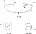
- the bottom section 348 includes an outer surface having a plurality of prisms 352. According to an exemplary embodiment, the prisms 352 are rounded prisms as shown, for example, in FIG. 55 . The size, shape, spacing, and configuration of the prisms 352 can vary depending on the desired light output.
- the first and second top sections 350 extend from the bottom section 348 toward the center of the lens 314.
- the first and second top sections 348 each have an inner surface and a set of prisms 352 extending from the inner surface.
- First and second flanges 354 extend from the first and second top sections 348, respectively. When assembled, the first and second flanges 354 engage with the first side channel 342 of the rail 312.
- the driver 318 is connected to the light rail 312 through one or more driver brackets 320.
- the driver bracket 320 has a substantially U-shaped body with a top section, first and second side sections, and first and second flanges extending from the first and second side sections, respectively.
- the driver bracket 320 is made from metal, for example stainless steel, although in alternative embodiments, other materials may be used.
- the driver 318 may be positioned in the light rail 312 center channel 346 and one or more driver brackets 320 are positioned over the driver 318 and connected to the light rail 312, for example through engagement of the driver bracket 320 flange and the lip formed between the first and second portions of the first and second arms 334.
- the driver bracket 320 may be slidable connected or snap fit to the light rail 312.
- the cover 324 is substantially U-shaped with a curved top surface and first and second sides extending downwardly from the top surface.
- the cover 324 has a first end and a second with a substantially U-shaped slot 356 positioned at each end.
- An aperture 358 is positioned near each slot 356.
- the slot 356 accommodates for the passage of one or more conductors, for example a cable 360 that connects the driver to a power source such as a hardwired connection.
- the aperture 358 allows for passage of a fastener to connect the cover 324 to the end bracket 326.
- the cover 324 is made from metal, for example aluminum, and is extruded to any desired length. In alternative embodiments, other materials and methods of manufacture may be used.
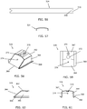
- FIGS. 58-61 shows a first exemplary embodiment of an end bracket 326 having a top section 362, an angled front wall 364, first and second side walls 366, and first and second flanges 368 extending from the first and second side walls 366, respectively.
- the top section 362 includes a center portion and angled side portions.
- the center portion includes a first aperture 370 and a second aperture 372.
- the first aperture 370 of the end bracket 326 aligns with the aperture 358 of the cover 324 to receive a fastener, connecting the cover 324 to the end bracket 326.
- the second aperture 372 of the end bracket 326 aligns with the substantially U-shaped slot 356 of the cover 324.
- the cable 360 extends through the slot 356 and the second aperture 372 to connect to the driver 320.
- the edges of the cover 324 surrounding the slot 356 extend over at least a portion of the end bracket 326, for example the angled side portions.
- the front wall 364 includes a stud 374 for a grounding connection.
- a grounding wire and eyelet (not shown) are fastened with a hex nut and connected to the stud 375. This connection provides grounding for the driver 318.
- the end bracket 326 is connected to the light rail 312 with the first and second flanges 368 retaining the end bracket 326 in the center channel 346 of the light rail 312. In various exemplary embodiments, the end bracket 326 can be slidably connected and/or snap connected to the light rail 312.
- the end cap 328 is connected to the light rail 312 over the end bracket 326.
- the end cap includes a bottom flange, and first and second mounting posts extending from a rear surface as shown in FIGS. 18-22 .
- the end cap 328 is inserted into the light rail 312 so that the bottom flange engages the inner surface of the bottom section of the lens 314 and the first and second mounting posts extend into the first and second hook channels, respectively.
- the end cap 328 can include an angled wall that aligns with the angled front wall of the end bracket 326
- the luminaire 310 is modular and capable of connecting with other modules.
- FIGS. 62 and 63 show another exemplary luminaire, configured as a longer luminaire, for example a six through eight foot luminaire.
- the luminaire includes a light rail 312 and a lens 314 connected to the light rail 312.
- the light rail 312 and lens 314 can be the same or similar to those of the luminaire 310 shown in FIG. 48 , but formed longer.
- a flexible LED sheet is connected to the light rail 312 and positioned between the light rail 312 and the lens 314.
- a single LED sheet or multiple LED sheets may be used.
- a first driver 318A and a second driver 318B are positioned on the light rail 312 and connected by one or more driver brackets 320.
- the drivers 318A, 318B are electrically connected to the one or more LED sheets.
- a first top cover 324A and a second top cover 324B are connected to the light rail 312 over the drivers 318A, 318B.
- a center bracket 376 is positioned in the light rail 312 to connect the first and second top covers 324A, 324B.
- First and second end brackets 326A, 326B are connected to the light rail 312 to enclose the sides of the drivers 318A, 318B.
- First and second end caps 328A, 328B are connected to the light rail 312 to enclose the sides of the light rail 312 and lens 314.
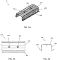
- FIGS. 64-66 show a center bracket 376 according to an exemplary embodiment.
- the center bracket 376 includes a top section 378, first and second side walls 380, and first and second flanges 382 extending from the first and second side walls 380, respectively.
- the top section 378 includes a first aperture 384 and a second aperture 386.
- the first aperture 384 of the center bracket 376 aligns with the aperture 358 of the first cover 324A to receive a fastener, connecting the first cover 324A to the center bracket 376.
- the second aperture 386 of the center bracket 376 aligns with the aperture 358 of the second cover 324B to receive a fastener, connecting the second cover 324B to the center bracket 376.
- the center bracket 376 can be slidably connected and/or snap connected to the light rail 312, for example the center channel 346, with the first and second flanges 382 assisting to secure the center bracket 376 to the light rail 312.
- FIGS. 67-73 show an exemplary embodiment of an extension assembly that can connect multiple luminaires or connect a similar extension to a luminaire, for example first and second luminaires 310A, 310B.
- the extensions assembly includes a joiner rail 388, a joiner bracket 390, and an optical spacer 392.
- the joiner rail 388 connects to the light rails 312A, 312B of the first and second luminaires 310A, 310B.
- the joiner bracket 390 connects to the joiner rail 388 and first and second top covers 324A, 324B.
- the optical spacer 392 connects to the joiner rail 388 and the first and second lens 314A, 314B.
- FIGS. 67 and 68 also show the luminaire connected to a suspension assembly having a cable 394, a mounting adapter 396, and a suspension bracket 398.
- the suspension bracket 398 includes a top section, first and second sides, and first and second hooks.
- the top section includes a top aperture for receiving the mounting adapter 396.
- the first and second sides include side apertures to reduce the weight and material of the suspension bracket and to increase the flexibility of the sides.
- the hooks connect to the light rail 312, for example with the third protrusion and/or the second side channel 344.
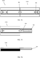
- FIGS. 74-75A show an exemplary embodiment of the joiner rail 388.
- the joiner rail 388 includes a bottom portion 400 and first and second arms 402 extending from the bottom portion 400.
- the bottom portion 400 includes a channel 404 bound by angled side walls and a top wall. The side walls engage the protrusions 338 that extend from the bottom 330 of the light rail 312, to help keep the joiner rail 388 in place.
- the bottom portion 400 includes a first pair of apertures to receive set screws to secure the joiner rail 388 to the light rail 312.
- the bottom portion 400 and the first and second arms 402 meet at a shoulder. When the joiner rail 388 is connected to the light rail 312, the shoulders slide into the center channel 346.
- the first and second arms 402 each include a second pair of apertures, as best shown in FIG. 75A , that are used to align the joiner rail 388 in the proper position with the light rail 312.
- FIGS. 76-78 show an exemplary embodiment of the joiner bracket 390.
- the joiner bracket 390 includes a top section 406 and first and second side walls 408.
- the top section 406 includes a first aperture 410 and a second aperture 412.
- the first aperture 410 of the joiner bracket 390 aligns with the aperture 358 of the first cover 324A to receive a fastener, connecting the first cover 324A to the joiner bracket 390.
- the second aperture 412 of the joiner bracket 390 aligns with the aperture 358 of the second cover 324B to receive a fastener, connecting the second cover 324B to the joiner bracket 390.
- the joiner bracket 390 is slidably connected to the light rails 312A, 312B.
- the joiner bracket 390 can include first and second flanges assisting to secure the joiner bracket to the light rails 312A, 312B, similar to the center bracket 376.
- FIGS. 79-81B show an exemplary embodiment of the optical spacer 392.
- the optical spacer 392 includes a central region 414 surrounded by an outer rim 416.
- the outer rim 416 has a substantially concave bottom section and first and second top sections.
- An outer flange 418 extends from the outer rim 416 on the bottom section and the first and second top sections.
- the outer flange 118 includes a plurality of prisms 420.
- the prisms 420 are rounded prisms as shown, for example, in FIG. 81B .
- the size, shape, spacing, and configuration of the prisms 420 can vary depending on the desired light output.
- the prisms 420 of the optical spacer 392 match the prisms 352 of the lens 314.
- the central region 414 bounds a channel 422 that slidable connects with the joiner rail 388.
- the optical spacer 392 is made from a polymer, for example acrylic.
- the optical spacer 392 can be translucent to allow light to pass through the spacer or it may be opaque.
- the joiner rail 388 is slid into the light rail 312A center channel 346 of a first luminaire 310A so that the first and second shoulders of the joiner rail 388 abut the light rail 312A.
- the cover 324A of the first luminaire 310A is connected to the joiner bracket 390 with a fastener.
- a set screw may then be inserted into the joiner rail 388 and tightened to assist in securing the joiner rail 388 to the light rail 312A.
- the optical spacer 392 can also be slid onto the joiner rail 388.
- the optical spacer 392 is positioned so that the outer rim 416 extends into the first luminaire 310A lens 314A.
- a second luminaire 310B is then similarly connected to the other side of the joiner rail 388.
- the outer flange 418 extending from the outer rim 416 of the optical spacer 392 is positioned between the two lenses 314A, 314B.
- FIG. 83 shows another exemplary embodiment of a luminaire used in connection with a control component, for example a sensor module 510, such as an occupancy sensor.
- the control component can include any device that is used to control or monitor the luminaire 500.
- the luminaire includes a light rail 512, a lens 514, an LED sheet (not shown), a driver 518 connected by one or more driver brackets 520, a top cover 524, first and second end brackets 526A, 526B, and first and second end caps 528A, 528B.
- the luminaire also includes a tray 530 and a shield 532. The tray 530 retains the sensor module 510 components and slidably connects to the light rail 512.
- a bracket 534 helps secure the sensor module 510 to the tray 530 and the light rail 512.
- the shield 532 is positioned between the light rail 512 and the lens 514 to cover the tray 530 and sensor components from view.
- FIG. 84 depicts a first exemplary type of sensor 510A having a round sensor.
- FIG. 85 depicts a second exemplary type of occupancy sensor 510B having a rectangular sensor.
- the configuration and components of such sensors are commercially available and would be understood by one of ordinary skill in the art. Different types of sensors, including occupancy, motion, and light sensors, can be used.
- the light rail 512 of the luminaire is similar to the light rails of the luminaires shown in in the prior figures except that the light rail 512 has am open slot 536 for receiving the tray 530.
- FIGS. 87-90 show an exemplary embodiment of the tray 530.
- the tray 530 includes a bottom 538, first and second side walls 540, and first and second end walls 542.
- First and second flanges 544 extend from the first and second side walls 540, respectively.
- the bottom 538 includes a circular opening 546 and a primary rectangular opening 548.
- the tray 530 can be inserted into the light rail 512 with either the circular opening 546 or rectangular opening facing outwardly 548, toward the end of the light rail 312, depending on the type of sensor module used.
- the light rail 512 and the tray 530 can be used with different luminaire components depending on the type of sensor module.
- the tray 530 may be modified to include any size, shape, or configuration of opening to accommodate different sensors.
- FIG. 91 depicts an exemplary lens 514A for use with the round sensor 510A.
- the lens includes a round aperture 550 to allow the sensor to pass through the lens.
- FIG. 92 depicts and exemplary lens 514B for use with the rectangular sensor 510B.
- the lens 514B includes a rectangular aperture 552 to allow the sensor 310B to pass through the lens 514B.
- FIG. 93 depicts an exemplary shield 532A for use with the round occupancy sensor 510A.
- the shield 532A includes a round aperture 554 to allow the sensor to pass through the shield 532A.
- FIG. 94 depicts an exemplary shield 532B for use with the rectangular sensor 510B.
- the shield 532B includes a rectangular aperture 556 to allow the sensor to pass through the shield 532B.
- the appropriate shield 532 can be positioned inside of the lens 514 to hide the tray 530 and sensor components from view through the lens 514.
- the shield 532 is made from an opaque material.
- the shield 532 can be made from a thin solid piece of material that can be flexed or bent to fit within the lens 514. For example, the shield 532 may flex along the broken lines shown in FIGS. 93 and 94 .
- the shields 532 can be made from a polymer, for example PVC, metal, elastomer, or other suitable flexible material.
- FIG. 95 depicts the luminaire used with a control system 510C, for example a wireless automation and control system, that is placed in the tray 530 and connected to the light rail 512 as discussed above.
- a control system 510C for example a wireless automation and control system
- An exemplary commercial embodiment of such a system is the wiHUBBTM system by Hubbell Incorporated.
- the control system 510C does not utilize a sensor, and therefore is used in connection with a shield 510C that does not have an opening and covers the entire tray 530.
- the control system 510C is connected to one or more drivers 518 to control the light output of the luminaire 500.
- FIGS. 98-100 illustrate another exemplary luminaire 610.
- the LED light sheet 616 is mounted to the light rail 614 with the LED sheet 616 wrapping around the bottom section 630 and first and second hooks 648 of the light rail 614.
- the LED light sheet 616 is arranged on the light rail 614 so that at least one row of LEDs 686 is positioned in or substantially underneath the cylindrical groove 640 of the lens 612.
- the LED light sheet 616 is connected to the light rail 614 through an adhesive, for example a double-sided tape, although other adhesives or a mechanical connection, such as clips or fasteners, may also be used.
- the lens 612 is connected to the light rail 612 by connecting the first and second flanges 644 of the first and second arms 650 of the lens 612 with the first side channel 678 of the light rail 614, respectively.
- the first and second flanges 650 can be slidably connected into the first side channels 678 or they may be snap or pressed fit into the channels, with the flanges 644 pressing past and flexing the angled surface of the angled prong.
- a top cover 624 is connected to the light rail 614 by engaging a flange of the top cover 624 with the second notches 672 formed in the second portions 662 of the light rail 614 first and second arms 650.
- the top cover 24-2 may be slidable connected or snap fit to the light rail 614.
- a suspension bracket 722 having a top, angled sides, and a hook is connected to the light rail 614, for example through engagement of the suspension bracket hook and the light rail third protrusion 676 and/or second side channel 680.
- the suspension bracket 722 may be slidable connected, snap fit, or press fit to the light rail 614.
- the suspension bracket 722 may be resilient and expand as it is pressed over the light rail 614, with the hooks springing back towards their initial position after clearing the third protrusion 672.
- the top of the suspension bracket 722 includes an aperture for connecting to a suspension cable (not shown).
- the driver 618 is positioned in the light rail center channel 682 and connected to the light rail 614 through one or more driver brackets 622.
- the driver bracket 622 shown in FIGS. 97-100 has a bottom section 724 and first and second sidewalls 726 extending at an angle upwardly from the bottom section 724. The first and second sidewalls 726 engage an inwardly extending protrusion 728 on the first portions 660 of the light rail first and second arms 650.
- An aperture receives a fastener (not shown) to connect the driver bracket with a flange on the driver 618.
- the driver bracket 122-2 may be slidable connected or snap fit to the light rail 614.
- One or more electrical conductors extend from the driver 618 through the light rail 614 to connect to the LED sheet 616.
- FIG. 101 shows a second exemplary embodiment of a side cover 626 having a top section 730 and a bottom section 732.
- the second side cover 626 is configured to mate with the light rail 614 shown in FIGS. 97-100 .
- the bottom section 732 has a shoulder 734 that is wider than the top section 730, but lacks the substantially horizontal edge 736 of the first side cover.
- One or more projections 742 extend from the bottom section 732 to position the second side cover 726 on the light rail 714. The projections 742 abut the inwardly extending protrusion 728 on the first portions of the light rail 614 first and second arms 650.
- the side cover 626 is made from metal, for example stainless steel or aluminum. Other materials and configurations of side covers may be used depending on the configuration of the light rail 614 and the driver 618.
- FIGS. 102-103A show another alternative embodiment of a light rail 834 and lens 836 assembly.
- the light rail 834 has first and second arms 838 having a free end with a substantially V-shaped notch 840.
- the lens 836 has a series of substantially V-shaped protrusions 842 configured to mate with the V-shaped notch 840 of the light rail 834.
- the light rail 836 is adjustably positioned on the light rail 834 by engaging the notch 840 with different sets of protrusions 842.
- the terms “front,” “rear,” “upper,” “lower,” “upwardly,” “downwardly,” and other orientational descriptors are intended to facilitate the description of the exemplary embodiments of the present invention, and are not intended to limit the structure of the exemplary embodiments of the present invention to any particular position or orientation.
- Terms of degree, such as “substantially” or “approximately” are understood by those of ordinary skill to refer to reasonable ranges outside of the given value, for example, general tolerances associated with manufacturing, assembly, and use of the described embodiments.
Landscapes
- Engineering & Computer Science (AREA)
- General Engineering & Computer Science (AREA)
- Non-Portable Lighting Devices Or Systems Thereof (AREA)
- Arrangement Of Elements, Cooling, Sealing, Or The Like Of Lighting Devices (AREA)
- Fastening Of Light Sources Or Lamp Holders (AREA)
- Microelectronics & Electronic Packaging (AREA)
Description
- Various exemplary embodiments of the invention relate to luminaires, for example indoor luminaire.
- Luminaires, or light fixtures, are used with electric light sources to provide aesthetic and functional housing in both interior and exterior applications. Various types of interior luminaires include overhead, ceiling, or suspended luminaires, which are designed to be positioned near, or suspended from, the ceiling. Interior luminaires are typically made with either direct or indirect lighting elements. In recent years, lighting applications have trended towards the use of light emitting diodes (LEDs) as the light source in place of conventional incandescent and fluorescent lamps.
US 2011/0285314 A1 andUS 2009/0002978 A1 are examples of prior art luminaires. - The invention is defined by the subject-matter of
claim 1. Optional features are described in the dependent claims. The embodiments which are not covered byclaim 1 do not form part of the invention but are part of the overall disclosure and represent information that is useful for understanding the invention. - The aspects and features of various exemplary embodiments will be more apparent from the description of those exemplary embodiments taken with reference to the accompanying drawings, in which:
-
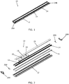
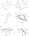
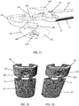
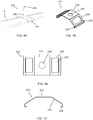
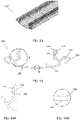
FIG. 1 is a perspective view of a luminaire according to a first exemplary embodiment; -
FIG. 2 is an exploded, perspective view of the luminaire ofFIG. 1 ; -
FIG. 3 is a front view of the lens ofFIG. 2 ; -
FIG. 3A is an enlarged front view of section A ofFIG. 3 ; -
FIG. 3B is an enlarged front view of section B ofFIG. 3 ; -
FIG. 3C is an enlarged front view of section C ofFIG. 3 ; -
FIG. 3D is an enlarged front view of section D ofFIG. 3C ; -
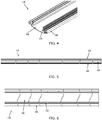
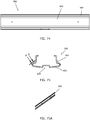
FIG. 4 is a perspective view of the light rail ofFIG. 2 ; -
FIG. 5 is a right side view of the light rail ofFIG. 4 ; -
FIG. 6 is a top view of the light rail ofFIG. 4 ; -
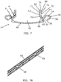
FIG. 7 is a front view of the light rail ofFIG. 4 ; -
FIG. 7A is a partial, sectional view ofFIG. 7 taken along line A-A and viewed in direction of the arrows; -
FIG. 8 is a right side view of the light sheet ofFIG. 2 ; -
FIG. 9 is a top view of the light sheet ofFIG. 8 ; -
FIG. 9A is an enlarged view of section A ofFIG. 9 ; -
FIG. 10 is a perspective view the driver bracket ofFIG. 2 ; -
FIG. 11 is a front view of the driver bracket ofFIG. 10 ; -
FIG. 12 is a perspective view of the grounding bracket ofFIG. 2 ; -
FIG. 13 is an exploded, perspective view of the grounding bracket and ground wire ofFIG. 2 ; -
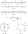
FIG. 14 is a top view of the top cover ofFIG. 2 ; -
FIG. 15 is a right side view of the top cover ofFIG. 14 ; -
FIG. 16 is a front view of the top cover ofFIG. 14 ; -
FIG. 16A is an enlarged view of area A ofFIG. 16 ; -
FIG. 17 is a perspective view of the side cover ofFIG. 2 ; -
FIG. 18 is a front perspective view of the end cap ofFIG. 2 ; -
FIG. 19 is a rear perspective view of the end cap ofFIG. 18 ; -
FIG. 20 is a right side view of the end cap ofFIG. 18 ; -
FIG. 21 is another rear perspective view of the end cap ofFIG. 18 ; -
FIG. 22 is a bottom view of the end cap ofFIG. 18 ; -
FIG. 22A is a right side sectional view ofFIG. 22 taken along line A-A and viewed in direction of the arrows; -
FIG. 23 is a perspective, partially exploded view of a luminaire according to an exemplary embodiment; -
FIG. 24 is a perspective view of an extending cover according to an exemplary embodiment; -
FIG. 25 is a front view of the extending cover ofFIG. 24 ; -
FIG. 26 is a right side view of the extending cover ofFIG. 24 ; -
FIG. 26A is an enlarged sectional view ofFIG. 26 taken along line A-A and viewed in direction of the arrows; -
FIG. 27 is a top perspective view of a luminaire and a sensor module according to an exemplary embodiment; -
FIG. 28 is a bottom perspective view of the luminaire and sensor module ofFIG. 27 ; -
FIG. 29 is an exploded, bottom perspective view of the luminaire and sensor module ofFIG. 27 ; -
FIG. 30 is an exploded, top perspective view of the luminaire and sensor module ofFIG. 27 ; -
FIG. 31 is another exploded, perspective view of the luminaire and sensor module ofFIG. 27 ; -
FIG. 32 is a bottom perspective view of a first sensor module used with the luminaire according to various exemplary embodiments; -
FIG. 33 is a bottom perspective view of a second sensor module used with the luminaire according to various exemplary embodiments; -
FIG. 34 is a perspective view of a connector plate and optical spacer according to an exemplary embodiment; -
FIG. 35 is a perspective view of the connector plate ofFIG. 34 ; -
FIG. 36 is a top view of the connector plate ofFIG. 35 ; -
FIG. 37 is a front view of the connector plate ofFIG. 35 ; -
FIG. 38 is a perspective view of the optical spacer ofFIG. 34 ; -
FIG. 39 is a top plan view of the optical spacer ofFIG. 38 ; -
FIG. 40 is a front view of the optical spacer ofFIG. 38 ; -
FIG. 40A is a sectional view of the optical spacer ofFIG. 40 taken along line A-A and viewed in direction of the arrows; -
FIG. 40B is an enlarged view of the area B ofFIG. 40 ; -
FIG. 41 is a perspective view of the connector plate and optical spacer ofFIG. 34 partially inserted into a first luminaire; -
FIG. 42 is a perspective view of the connector plate and optical spacer ofFIG. 34 fully inserted into a first luminaire; -
FIG. 43 is a perspective view of a first and second luminaire connected with the connector plate and optical spacer ofFIG. 34 ; -
FIG. 44 is a perspective view of a suspension bracket connected to a luminaire according to an exemplary embodiment; -
FIG. 45 is a perspective view of the suspension bracket ofFIG. 44 ; -
FIG. 46 is a top view of the suspension bracket ofFIG. 45 ; -
FIG. 47 is a front view of the suspension bracket ofFIG. 45 ; -
FIG. 48 is an exploded, perspective view of another exemplary luminaire; -
FIG. 49 is a perspective view of the luminaire ofFIG. 48 ; -
FIG. 50 is a top view of the luminaire ofFIG. 48 ; -
FIG. 51 is a left side view of the luminaire ofFIG. 48 ; -
FIG. 52 is a front view of the luminaire ofFIG. 48 ; -
FIG. 53 is a partial perspective view of the light rail ofFIG. 48 ; -
FIG. 54 is a front view of the light rail ofFIG. 53 ; -
FIG. 54A is an enlarged view of area A ofFIG. 54 ; -
FIG. 54B is an enlarged view of area B ofFIG. 54 ; -
FIG. 55 is a front view of the lens ofFIG. 48 ; -
FIG. 55A is an enlarged view of area A ofFIG. 55 ; -
FIG. 55B is an enlarged view of area B ofFIG. 55 ; -
FIG. 56 is a top view of the cover ofFIG. 48 ; -
FIG. 57 is a front view of the cover ofFIG. 56 ; -
FIG. 58 is a perspective view of the end bracket ofFIG. 48 ; -
FIG. 59 is a top view of the end bracket ofFIG. 58 -
FIG. 60 is a right side view of the end bracket ofFIG. 58 ; -
FIG. 61 is a rear view of the end bracket ofFIG. 61 ; -
FIG. 62 is an exploded, perspective view of another exemplary luminaire; -
FIG. 63 is a perspective view of the luminaire ofFIG. 62 ; -
FIG. 64 is a perspective view of the center bracket ofFIG. 62 ; -
FIG. 65 is a top view of the center bracket ofFIG. 64 ; -
FIG. 66 is a front view of the center bracket ofFIG. 64 ; -
FIG. 67 is a partially exploded, perspective view of another exemplary luminaire; -
FIG. 68 is a perspective view of the luminaire ofFIG. 67 ; -
FIG. 69 is an exploded, perspective view of the first portion of the luminaire ofFIG. 67 ; -
FIG. 70 is a perspective view of the first portion of the luminaire ofFIG. 67 ; -
FIG. 71 is a top view of the luminaire ofFIG. 67 ; -
FIG. 72 is a top view of the first portion of the luminaire ofFIG. 67 ; -
FIG. 73 is a right side view of the first portion of the luminaire ofFIG. 67 ; -
FIG. 74 is a top view of the joiner rail ofFIG. 67 ; -
FIG. 75 is a front view of the joiner rail ofFIG. 64 ; -
FIG. 75A is a partial, sectional view ofFIG. 75 taken along line A-A and viewed in direction of the arrows; -
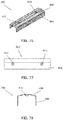
FIG. 76 is a perspective view of the joiner bracket ofFIG. 67 ; -
FIG. 77 is a top view of the joiner bracket ofFIG. 76 ; -
FIG. 78 is front view of the joiner bracket ofFIG. 76 ; -
FIG. 79 is a perspective view of the optical spacer ofFIG. 67 ; -
FIG. 80 is a top view of the optical spacer ofFIG. 79 ; -
FIG. 81 is a front view of the optical spacer ofFIG. 79 ; -
FIG. 81A is a sectional view ofFIG. 81 taken along line A-A and viewed in direction of the arrows; -
FIG. 81B is an enlarged view of area B inFIG. 81 ; -
FIG. 82 is a right side view of the optical spacer ofFIG. 79 ; -
FIG. 83 is an exploded, perspective view of another exemplary luminaire; -
FIG. 84 is an exploded, perspective view of the tray ofFIG. 83 and an exemplary sensor unit; -
FIG. 85 is an exploded, perspective view of the tray ofFIG. 83 and another exemplary sensor unit; -
FIG. 86 is a partial top view of the rail ofFIG. 83 ; -
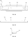
FIG. 87 is a perspective view of the tray ofFIG. 83 ; -
FIG. 88 is a top view of the tray ofFIG. 87 ; -
FIG. 89 is a right side view of the tray ofFIG. 87 ; -
FIG. 90 is a front view of the tray ofFIG. 87 ; -
FIG. 91 is a top view of the lens ofFIG. 83 ; -
FIG. 92 is a top view of another exemplary lens; -
FIG. 93 is a top view of the shield ofFIG. 83 ; -
FIG. 94 is a top view of another exemplary shield; -
FIG. 95 is an exploded, perspective view of another exemplary luminaire with a control module; -
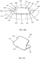
FIG. 96 is a perspective view of another exemplary shield; -
FIG. 97 is a front view of the shield ofFIG. 96 ; -
FIG. 98 is a perspective view of a partially assembled luminaire according to another exemplary embodiment; -
FIG. 99 is a perspective view of the partially assembled luminaire ofFIG. 98 with the light rail partially removed from the lens; -
FIG. 100 is a front view of the partially assembled luminaire ofFIG. 98 ; -
FIG. 101 is a perspective view of a side cover for use with the luminaire ofFIG. 98 according to an exemplary embodiment; -
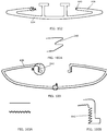
FIG. 102 is a front view of a light rail according to another exemplary embodiment; -
FIG. 102A is an enlarged view of the area A ofFIG. 102 ; -
FIG. 103 is a front view of a lens according to another exemplary embodiment; -
FIG. 103A is an enlarged view of the area A ofFIG. 103 ; and -
FIG. 103B is an enlarged view of the area B ofFIG. 103 . - According to various exemplary embodiments as illustrated in one or more of the drawings, a
luminaire 10 includes alens 12 connected to a support, for example alight rail 14. A flexible light emitting diode (LED)sheet 16 is connected to thelight rail 14 and positioned between thelight rail 14 and thelens 12. Adriver 18 is positioned on thelight rail 14 and connected by one ormore driver brackets 20. Thedriver 18 is electrically connected to theLED sheet 16. Agrounding bracket 22 electrically grounds thedriver 18 to thelight rail 14. Atop cover 24 is connected to thelight rail 14 over thedriver 18. First and second side covers 26A, 26B are connected to thelight rail 14 to enclose the sides of the driver. First andsecond end caps light rail 14 to enclose the sides of thelight rail 14 andlens 12. - As best shown in
FIG. 3 , and in accordance with further exemplary embodiments, thelens 12 includes abottom section 30 and first and secondtop sections 32. In various exemplary embodiments, thelens 12 is made from a polymer material, for example acrylic, and is extruded to any desired length. In alternative embodiments, other materials and methods of manufacture may be used. Thebottom section 32 has a concave curve extending to a first and second corner. Thebottom section 32 includes an outer surface having a plurality ofprisms 34. The term prism is used herein not to describe a specific structure, but to refer to a feature for directing, dispersing, diffusing, or otherwise modifying emitted light. According to an exemplary embodiment, theprisms 34 are rounded prisms as shown, for example, inFIG. 3A . The size, shape, spacing, and configuration of theprisms 34 can vary depending on the desired light output. - The first and second
top sections 32 extend from thebottom section 30 towards the center of thelens 12. A first set ofprisms 36 extends from the inner surface of the first and secondtop sections 32. A first andsecond arm 38 extend from the first and secondtop sections 32, respectively. According to the exemplary embodiment, the first andsecond arms 38 include various curvilinear and rectilinear inner and outer surfaces as shown inFIG. 3B . First and secondcylindrical grooves 40 extend into the first andsecond arms 38, respectively. A plurality ofprisms 42 extend from the inner surface of thegrooves 40. According to an exemplary embodiment, theprisms 36 extending from the first and second top sections and theprisms 42 extending from thecylindrical grooves 40 are rounded prisms as shown inFIGS. 3B-3D . The size, shape, spacing, and configuration of theprisms first flange 44 and a second flange extend from the first andsecond arms 38, respectively. - As best shown in
FIGS. 4-7A , and in accordance with further exemplary embodiments, the support orlight rail 14 includes abottom portion 46, first and second side hooks 48, and first andsecond arms 50 extending form the side hooks 48. In various exemplary embodiments, thelight rail 14 is made from metal, for example aluminum, and is extruded to any desired length. In alternative embodiments, other materials and methods of manufacture may be used. Various exemplary embodiments of thelight rail 14 have the capability to flex or bow a certain amount depending on the luminaire configuration. As best shown inFIG. 7 , thebottom portion 46 has a concave curve extending to a first end and a second end. Thehooks 48 extend from the bottom section proximate the first and second ends. The first andsecond arms 50 extend from the first and second hooks 48. Both sides of thelight rail 14 have similar configurations and only one side may be described herein for clarity. - According an exemplary embodiment, the
hooks 48 have a substantially planarfirst section 52 extending from thebottom portion 46 at an oblique angle away from the center of thelight rail 14, a substantially planarsecond section 54 extending from thefirst section 52 at an oblique angle away from the center of thelight rail 14, and a curvedthird section 56 curving from thesecond section 54 downwardly and back towards the center of thelight rail 14. The first andsecond hooks 48 bound a first andsecond hook channel 58, respectively, with the free end of the first andsecond hooks 48 spaced from thebottom section 46 to define an opening. - The first and
second arms 50 include afirst portion 60 and asecond portion 62. In various exemplary embodiments, thefirst portion 60 of the first andsecond arms 50 extends from thefirst section 52 of the first andsecond hooks 48 at an oblique angle towards the center of thelight rail 14. Each of thefirst portions 60 include afirst notch 64 extending into an outer surface andfirst protrusions 66 extending outwardly from the outer surface. As best shown inFIG. 7A , thefirst portions 60 include one ormore openings 68, for example wireway or alignment openings. In various exemplary embodiments, thesecond portions 62 extend outwardly from the respectivefirst portions 60 with a substantially vertical orientation. A first end of the second portions extends below the first portion to form alip 70. Each of thesecond portions 62 include asecond notch 72 formed into an inner surface, outwardly facingsecond protrusions 74 having an angled prong extending from an outer surface, and outwardly extendingthird protrusions 76 extending from the outer surface. The first andsecond protrusions third protrusions second side channel 80. Thelight rail bottom 46, first andsecond hooks 48, and first andsecond arms 50 bound acenter channel 82. - As best shown in
FIGS. 8-9A , and in accordance with further exemplary embodiments, theLED sheet 16 includes a sheet offlexible material 84 with a plurality of LEDs. In various exemplary embodiments, the LEDs are LEDmodules 86 that are contained units having a dome-shaped lens surrounding one or more light generating elements and necessary circuitry (not shown). Various types ofLED modules 86 may be used depending on the performance requirements and the desired output as would be understood by one of ordinary skill in the art. TheLED modules 86 extend from a single surface of theflexible material 84. According to an exemplary embodiment, theflexible material 84 is a polymer or composite sheeting or other suitable material having one or more layers, for example, two layers of polymer sheeting sandwiching conductor pathways andLED modules 86. - As shown in
FIG. 9 , theLED modules 86 are arranged in different patterns, for example, an outer pattern and an inner pattern. In various exemplary embodiments, the outer most rows ofLED modules 86 on each side of theLED sheet 16 are configured for up-lighting or indirect lighting, while the remainingLED modules 86 are configured for down-lighting or direct lighting. -
Connectors 88 are positioned at first and second corners of the LED sheet. Theconnectors 88 are electrically connected to one ormore drivers 18, for example through a conductor. Multiple paths or traces electrically connect theconnectors 88 to the plurality ofLED modules 86. In various exemplary embodiments, theconnectors 88 are surface mount terminal block type connectors. Theconnectors 88 can be configured to connect to one or more similar or identical connectors, for example through conductors or connecting links, so thatmultiple LED sheets 16 can be connected together as desired. - As best shown in
FIG. 2 , and in accordance with further exemplary embodiments, thedriver 18 is connected to thelight rail 14 through one ormore driver brackets 20. An exemplary embodiment of thedriver bracket 20 is shown inFIGS. 10 and 11 . Thedriver bracket 20 has a substantially U-shaped body with atop section 90, first andsecond side sections 92, and first andsecond flanges 94 extending from the first andsecond side sections 92, respectively. In various exemplary embodiments, thedriver bracket 20 is made from metal, for example stainless steel, although in alternative embodiments, other materials may be used. - The
driver 18 is grounded to thelight rail 14 through agrounding bracket 22. According to the exemplary embodiment shown inFIGS. 12 and 13 thegrounding bracket 22 is substantially U-shaped having abottom section 96 and first andsecond sides 98 extending upwardly from thebottom section 96. In various exemplary embodiments, thegrounding bracket 22 is made from metal, for example stainless steel, although in alternative embodiments, other materials may be used. Thebottom section 96 includes anaperture 100 and the first and second sidewalls each include an outwardly extendingtine 102. - According to an exemplary embodiment, the
grounding bracket 22 is positioned on thelight rail 14 with apost 104 extending through theaperture 100. Agrounding wire 106 having aneyelet 108 extends from thedriver 18 and is positioned on thepost 104 and secured thereto. In various exemplary embodiments, thepost 104 is threaded and anut 110 is fastened to thepost 104 to secure thegrounding wire 106. In other embodiments, thegrounding wire 106 may be soldered to thepost 104. - As best shown in
FIGS. 14-16A , and in accordance with further exemplary embodiments, thecover 24 is substantially U-shaped with a curvedtop surface 112 and first andsecond sides 114 extending downwardly from thetop surface 112. The first andsecond sides 112 include one ormore protrusions 116 extending from an outer surface away from the center of thecover 24. Theprotrusions 116 may be formed through pressing, stamping, or punching the first and second sides to form rounded deformations therein. One or moretop apertures 118 extend through the top of thecover 24 and one ormore side apertures 120 extending through the sides of thecover 24. In various exemplary embodiments, thecover 24 is made from metal, for example aluminum, and is extruded to any desired length. In alternative embodiments, other materials and methods of manufacture may be used. - A
driver 18 can be positioned in thelight rail 14center channel 82 and one ormore driver brackets 20 are positioned over thedriver 18 and connected to thelight rail 14, for example through engagement of thedriver bracket 20flange 94 and thelip 70 formed between the first andsecond portions second arms 50. Thedriver bracket 20 may be slidable connected or snap fit to thelight rail 14. Also, thegrounding bracket 22 is connected to thelight rail 14center channel 82, for example through engagement of thetines 102 and thelip 70 formed between the first andsecond portions second arms 50. Thegrounding bracket 22 may be slidable connected or snap fit to thelight rail 14. Thetop cover 24, shown in the exemplary embodiment ofFIGS. 14-16A , is connected to thelight rail 14 by engagement of theprotrusions 116 with thesecond notches 72 formed in thesecond portions 62 of thelight rail 14 first andsecond arms 50. Thetop cover 24 may be slidable connected to snap fit to thelight rail 14. -
FIG. 17 shows an exemplary embodiment of aside cover 26 having atop section 130 and abottom section 132. In various exemplary embodiments, theside 26 cover is configured to mate with thelight rail 14 shown inFIGS. 3-6 . Thebottom section 132 has first andsecond shoulders 134 that are wider than the top section and include at least one substantiallyhorizontal edge 136. Theshoulders 134 are designed to abut thelip 70 formed between the first andsecond portions second arms 50. One or more protursions (shown inFIG. 1A ) may extend from thebottom section 132 to position theside cover 26 on thelight rail 14. Thefirst side cover 26 includes atop slot 138 and abottom slot 140 for mating with anend cap 28. -
FIGS. 18-22A show anexemplary end cap 28. Theend cap 28 includes afront surface 144 and arear surface 146. Thefront surface 144 has anangled wall 148 extending away from thefront surface 144. Extending from theangled wall 148 is atop flange 150. Abottom flange 152 extends from therear surface 146. First and second mountingposts 154 extend from therear surface 146 and have a substantially sideways V-shape with a rounded corner. Afirst tab 156 and asecond tab 158 extend from theangled wall 148. In various exemplary embodiments, theend cap 28 is translucent to allow light emitted from the luminaire to diffuse through the ends. In other alternative embodiments, theend cap 28 is opaque or has a varying degree of opacity. -
FIG. 23 shows theexemplary side cover 26 and theexemplary end cap 28 being inserted into thelight rail 14. Theside cap 26 is slid into thecenter channel 82 of thelight rail 14 so that the shoulder abuts 134 or fits inside thelip 70. Theend cap 28 is then inserted so that thebottom flange 152 engages the inner surface of the of thebottom section 30 of thelens 12 and the first and second mountingposts 154 extend into the first andsecond hook channels 58, respectively. Thefirst tab 156 of theend cap 28 engages thebottom slot 140 of theside cover 26 and thesecond tab 158 of the first end cap engages thetop slot 138 of theside cover 26. The end captop flange 150 is positioned over thelight rail 14 and adjacent to, in direct contact with, or overlapping thetop cover 24. Another end cap and side cover are connected to the opposite side of thelight rail 14. The side covers 62 provide an enclosure for thedriver 18. - In accordance with various exemplary embodiments, the
luminaire 10 is modular and capable of connecting with other modules as discussed in further detail below.FIGS. 24-26A show an exemplary extendingcover 160 for use with theluminaire 10. The extendingcover 160 includes a curvedtop surface 162 and first andsecond sides 164 extending downwardly from thetop surface 162. The first andsecond sides 164 include one ormore protrusions 166 extending from an outer surface away from the center of the extendingcover 160. Theprotrusions 166 may be formed through pressing, stamping, or punching the first andsecond sides 164 to form rounded deformations therein. One ormore side apertures 168 extend through thesides 164 of the extendingcover 160. In various exemplary embodiments, the extendingcover 160 is made from metal, for example aluminum, and is extruded to any desired length. In alternative embodiments, other materials and methods of manufacture may be used. - As best shown in
FIGS. 27-33 , and in accordance with further exemplary embodiments, the extendingcover 160 is used to connect asensor module 170 to theluminaire 10. Thesensor module 170 includes asensor cover 172 connected to asensor rail 174. In an exemplary embodiment, thesensor cover 172 has similar features to thelens 12 and thesensor rail 174 has similar features to thelight rail 172. The extendingcover 160protrusions 166 connect to thesecond notch 72 on thelight rail 14 and a similar inner notch 176 on thesensor rail 174. - As best shown in
FIG. 31 , thesensor cover 172 includes afirst aperture 178, for example a circular opening, and anadapter plate 180 positioned in the aperture. Thesensor rail 174 includes asecond aperture 182, for example a substantially rectangular opening. Asensor 184 is positioned adjacent thefirst aperture 178 in thesensor cover 172 and extends through thesecond aperture 182 in thesensor rail 174. In the exemplary embodiment shown inFIGS. 29 and32 , theadaptor plate 180 includes two openings and can be used with asensor 184 having more than one detection capability, or two integrated sensors. As best shown inFIGS. 31-33 , and in accordance with further exemplary embodiments, theadaptor plate 180 is interchangeable with other adaptor plates, for example theadaptor plate 181 with a single opening, so that different types of sensors may be used with thesame sensor module 170. Various types of exemplary sensors include, but are not limited to, infrared sensors, dimming photosensors, motion sensors, noise sensors, occupancy sensors, and daylight sensors. - In various exemplary embodiments, the extending
cover 160 is used in connection with aconnector plate 186 and anoptical spacer 198 to connect multiple luminaries. As best shown inFIGS. 34-37 , and in accordance with further exemplary embodiments, theconnector plate 186 includes a first and second ends 188, 190, first andsecond side flanges 192, and first andsecond tines 194. The first andsecond side flanges 192 extend at an angle away from the center of theconnector plate 186. The first andsecond tines 194 extend outwardly from a central region of theconnector plate 186 and include an aperture for receiving a mechanical fastener, for example a set screw (not shown). In various exemplary embodiments, the first andsecond side flanges 192 and the first andsecond tines 194 are resilient. The first andsecond flanges 192 include anotch 196. In various exemplary embodiments, the connector is made from metal, for example galvanized steel, although other materials may be used. - As best shown in
FIGS. 38-40B , and in accordance with further exemplary embodiments, theoptical spacer 198 includes acentral region 200 surrounded by anouter rim 202. Theouter rim 202 has a substantially concave bottom section and first and second top sections. Anouter flange 204 extends from theouter rim 202 on the bottom section and the first and second top sections. First and secondspacer arms 206 extend from the first and second top sections, respectively. The first and secondspacer arms 206 include acircular portion 208 and an angledplanar portion 210. Thecentral region 200 bounds a spacer channel 212. First andsecond projections 214 extend from thecentral region 200 into the spacer channel 212. In various exemplary embodiments, theoptical spacer 198 is made from a polymer, for example acrylic. Theoptical spacer 198 can be translucent to allow light to pass through the spacer or it may be opaque. - As best shown in
FIGS. 41-43 , theconnector plate 186 is slid into thelight rail 14center channel 82 of afirst luminaire 10A so that the first andsecond side flanges 192 abut thelight rail 14, for example the first andsecond arms 20, or thelip 70 formed between the first andsecond portions second arms 50. Theoptical spacer 198 is then slid onto theconnector plate 186 with theconnector plate 186 sliding through the spacer channel 212 and the first andsecond projections 214 abutting the first andsecond side flanges 192 and resting in thenotch 196. Theoptical spacer 198 is positioned so that theouter rim 202 extends into thefirst 12, with theluminaire 10A lenscircular portion 208 of thefirst spacer arm 206 extending into thecylindrical groove 40 of thelens 12. A set screw may then be inserted into thefirst tine 194 of theconnector plate 186 and tightened to assist in securing theconnector plate 186 to thelight rail 14. Asecond luminaire 10B is then similarly connected to the other side of theconnector plate 186. When twoluminaires outer flange 204 extending from theouter rim 202 of theoptical spacer 198 is positioned between the two. The extendingcover 160 can be slidably connected to the assembly prior to connection of thesecond luminaire 10B, or the extendingcover 160 can be press fit into place after bothluminaires -
FIG. 44 shows aluminaire 10 connected to asuspension assembly 216 having acable 218, a mountingadapter 220, and asuspension bracket 222. As best shown inFIGS. 46 and 47 , and in accordance with further exemplary embodiments, thesuspension bracket 222 includes atop section 224, first andsecond sides 226, and first andsecond hooks 228. Thetop section 224 includes atop aperture 230 for receiving the mountingadapter 220. The first andsecond sides 226 includeside apertures 230 to reduce the weight and material of the suspension bracket and to increase the flexibility of thesides 226. Thehooks 228 connect to alight rail 14, for example with the third protrusion 75 and/or thesecond side channel 80. -
FIGS. 48-52 depict another exemplary aluminaire 310 that includes a support, for example alight rail 312 or other suitable support, and alens 314 connected to thelight rail 312. A flexible light emitting diode (LED) sheet is connected to thelight rail 312 and positioned between thelight rail 312 and thelens 314. Adriver 318 is positioned on thelight rail 312 and connected by one ormore driver brackets 320. Thedriver 318 is electrically connected to the LED sheet. Atop cover 324 is connected to thelight rail 312 over thedriver 318. First andsecond end brackets light rail 312 to enclose the sides of thedriver 318. First andsecond end caps light rail 312 to enclose the sides of thelight rail 12 andlens 14. In an exemplary embodiment, the components of theluminaire 10 can be configured as a two foot through four foot luminaire. - As best shown in
FIGS. 53-54B , and in accordance with further exemplary embodiments, thelight rail 312 includes abottom portion 330, first and second side hooks 332, and first andsecond arms 334 extending form the side hooks 332. In various exemplary embodiments, thelight rail 312 is made from metal, for example aluminum, and is extruded to any desired length. In alternative embodiments, other materials and methods of manufacture may be used. Various exemplary embodiments of thelight rail 312 have the capability to flex or bow a certain amount depending on the luminaire configuration. As best shown inFIG. 54 thebottom portion 330 has a concave curve extending to a first end and a second end. The first andsecond hooks 332 extend from thebottom section 330 proximate the first and second ends. The first andsecond arms 334 extend from the first andsecond hooks 332. The bottom portion includes anotch 336 in the outer surface and a pair ofprotrusions 338 extending from the inner surface. Thenotch 336 acts as a drill point guide and theprotrusions 338 assist in retaining ajoiner rail 388 as discussed in further detail below. - According to an exemplary embodiment, the first and
second hooks 332 have a substantially planar first section extending from thebottom portion 330 at an oblique angle away from the center of thelight rail 312, a substantially planar second section extending from the first section at an oblique angle away from the center of thelight rail 312, and a third section curving from the second section downwardly and back towards the center of thelight rail 312. The first andsecond hooks 332 bound a first andsecond hook channel 340, respectively, with the free end of the first andsecond hooks 332 spaced from thebottom section 330 to define an opening. - The first and
second arms 334 include a first portion and a second portion. In various exemplary embodiments, the first portion of the first andsecond arms 334 extends from the first section of the first andsecond hooks 332 at an oblique angle towards the center of thelight rail 312. Each of the first portions include a first notch extending into an outer surface and first protrusions extending outwardly from the outer surface. In an exemplary embodiment, the first portions include one or more wireway openings (not shown). In various exemplary embodiments, the second portions extend outwardly from the respective first portions with a substantially vertical orientation. A first end of the second portion extends below the first portion to form a lip. Each of the second portions include a second notch formed into an inner surface, outwardly facing second protrusions having an angled prong extending from an outer surface, and outwardly extending third protrusions extending from the outer surface. The first and second protrusions bound afirst side channel 342 and the second and third protrusions bound asecond side channel 344. Thelight rail bottom 330, first andsecond hooks 332, and first andsecond arms 334 bound acenter channel 346. - As best shown in
FIGS. 55-55B , and in accordance with further exemplary embodiments, thelens 314 includes abottom section 348, and first and secondtop sections 350. In various exemplary embodiments, thelens 314 is made from a polymer material, for example acrylic, and is extruded to any desired length. In alternative embodiments, other materials and methods of manufacture may be used. Thebottom section 348 has a concave curve extending to a first and second corner. Thebottom section 348 includes an outer surface having a plurality ofprisms 352. According to an exemplary embodiment, theprisms 352 are rounded prisms as shown, for example, inFIG. 55 . The size, shape, spacing, and configuration of theprisms 352 can vary depending on the desired light output. - The first and second
top sections 350 extend from thebottom section 348 toward the center of thelens 314. The first and secondtop sections 348 each have an inner surface and a set ofprisms 352 extending from the inner surface. First andsecond flanges 354 extend from the first and secondtop sections 348, respectively. When assembled, the first andsecond flanges 354 engage with thefirst side channel 342 of therail 312. - As best shown in
FIG. 48 , and in accordance with further exemplary embodiments, thedriver 318 is connected to thelight rail 312 through one ormore driver brackets 320. Thedriver bracket 320 has a substantially U-shaped body with a top section, first and second side sections, and first and second flanges extending from the first and second side sections, respectively. In various exemplary embodiments, thedriver bracket 320 is made from metal, for example stainless steel, although in alternative embodiments, other materials may be used. - Although not shown, the
driver 318 may be positioned in thelight rail 312center channel 346 and one ormore driver brackets 320 are positioned over thedriver 318 and connected to thelight rail 312, for example through engagement of thedriver bracket 320 flange and the lip formed between the first and second portions of the first andsecond arms 334. Thedriver bracket 320 may be slidable connected or snap fit to thelight rail 312. - As best shown in
FIGS. 56 and 57 , and in accordance with further exemplary embodiments, thecover 324 is substantially U-shaped with a curved top surface and first and second sides extending downwardly from the top surface. Thecover 324 has a first end and a second with a substantiallyU-shaped slot 356 positioned at each end. Anaperture 358 is positioned near eachslot 356. Theslot 356 accommodates for the passage of one or more conductors, for example acable 360 that connects the driver to a power source such as a hardwired connection. Theaperture 358 allows for passage of a fastener to connect thecover 324 to theend bracket 326. In various exemplary embodiments, thecover 324 is made from metal, for example aluminum, and is extruded to any desired length. In alternative embodiments, other materials and methods of manufacture may be used. -
FIGS. 58-61 shows a first exemplary embodiment of anend bracket 326 having atop section 362, an angledfront wall 364, first andsecond side walls 366, and first andsecond flanges 368 extending from the first andsecond side walls 366, respectively. Thetop section 362 includes a center portion and angled side portions. The center portion includes afirst aperture 370 and asecond aperture 372. Thefirst aperture 370 of theend bracket 326 aligns with theaperture 358 of thecover 324 to receive a fastener, connecting thecover 324 to theend bracket 326. Thesecond aperture 372 of theend bracket 326 aligns with the substantiallyU-shaped slot 356 of thecover 324. Thecable 360 extends through theslot 356 and thesecond aperture 372 to connect to thedriver 320. The edges of thecover 324 surrounding theslot 356 extend over at least a portion of theend bracket 326, for example the angled side portions. Thefront wall 364 includes astud 374 for a grounding connection. In an exemplary embodiment, a grounding wire and eyelet (not shown) are fastened with a hex nut and connected to the stud 375. This connection provides grounding for thedriver 318. Theend bracket 326 is connected to thelight rail 312 with the first andsecond flanges 368 retaining theend bracket 326 in thecenter channel 346 of thelight rail 312. In various exemplary embodiments, theend bracket 326 can be slidably connected and/or snap connected to thelight rail 312. - The end cap 328 is connected to the
light rail 312 over theend bracket 326. In an exemplary embodiment, the end cap includes a bottom flange, and first and second mounting posts extending from a rear surface as shown inFIGS. 18-22 . The end cap 328 is inserted into thelight rail 312 so that the bottom flange engages the inner surface of the bottom section of thelens 314 and the first and second mounting posts extend into the first and second hook channels, respectively. The end cap 328 can include an angled wall that aligns with the angled front wall of theend bracket 326 - In accordance with various exemplary embodiments, the
luminaire 310 is modular and capable of connecting with other modules.FIGS. 62 and 63 show another exemplary luminaire, configured as a longer luminaire, for example a six through eight foot luminaire. The luminaire includes alight rail 312 and alens 314 connected to thelight rail 312. Thelight rail 312 andlens 314 can be the same or similar to those of theluminaire 310 shown inFIG. 48 , but formed longer. A flexible LED sheet is connected to thelight rail 312 and positioned between thelight rail 312 and thelens 314. A single LED sheet or multiple LED sheets may be used. Afirst driver 318A and asecond driver 318B are positioned on thelight rail 312 and connected by one ormore driver brackets 320. Thedrivers top cover 324A and a secondtop cover 324B are connected to thelight rail 312 over thedrivers center bracket 376 is positioned in thelight rail 312 to connect the first and second top covers 324A, 324B. First andsecond end brackets light rail 312 to enclose the sides of thedrivers second end caps light rail 312 to enclose the sides of thelight rail 312 andlens 314. -
FIGS. 64-66 show acenter bracket 376 according to an exemplary embodiment. Thecenter bracket 376 includes atop section 378, first andsecond side walls 380, and first andsecond flanges 382 extending from the first andsecond side walls 380, respectively. Thetop section 378 includes afirst aperture 384 and asecond aperture 386. Thefirst aperture 384 of thecenter bracket 376 aligns with theaperture 358 of thefirst cover 324A to receive a fastener, connecting thefirst cover 324A to thecenter bracket 376. Thesecond aperture 386 of thecenter bracket 376 aligns with theaperture 358 of thesecond cover 324B to receive a fastener, connecting thesecond cover 324B to thecenter bracket 376. In various exemplary embodiments, thecenter bracket 376 can be slidably connected and/or snap connected to thelight rail 312, for example thecenter channel 346, with the first andsecond flanges 382 assisting to secure thecenter bracket 376 to thelight rail 312. -
FIGS. 67-73 show an exemplary embodiment of an extension assembly that can connect multiple luminaires or connect a similar extension to a luminaire, for example first andsecond luminaires joiner rail 388, ajoiner bracket 390, and anoptical spacer 392. Thejoiner rail 388 connects to thelight rails 312A, 312B of the first andsecond luminaires joiner bracket 390 connects to thejoiner rail 388 and first and second top covers 324A, 324B. Theoptical spacer 392 connects to thejoiner rail 388 and the first andsecond lens -
FIGS. 67 and 68 also show the luminaire connected to a suspension assembly having acable 394, a mountingadapter 396, and asuspension bracket 398. In an exemplary embodiment, thesuspension bracket 398 includes a top section, first and second sides, and first and second hooks. The top section includes a top aperture for receiving the mountingadapter 396. The first and second sides include side apertures to reduce the weight and material of the suspension bracket and to increase the flexibility of the sides. The hooks connect to thelight rail 312, for example with the third protrusion and/or thesecond side channel 344. -
FIGS. 74-75A show an exemplary embodiment of thejoiner rail 388. Thejoiner rail 388 includes abottom portion 400 and first andsecond arms 402 extending from thebottom portion 400. Thebottom portion 400 includes achannel 404 bound by angled side walls and a top wall. The side walls engage theprotrusions 338 that extend from thebottom 330 of thelight rail 312, to help keep thejoiner rail 388 in place. Thebottom portion 400 includes a first pair of apertures to receive set screws to secure thejoiner rail 388 to thelight rail 312. Thebottom portion 400 and the first andsecond arms 402 meet at a shoulder. When thejoiner rail 388 is connected to thelight rail 312, the shoulders slide into thecenter channel 346. The first andsecond arms 402 each include a second pair of apertures, as best shown inFIG. 75A , that are used to align thejoiner rail 388 in the proper position with thelight rail 312. -
FIGS. 76-78 show an exemplary embodiment of thejoiner bracket 390. Thejoiner bracket 390 includes atop section 406 and first andsecond side walls 408. Thetop section 406 includes afirst aperture 410 and asecond aperture 412. Thefirst aperture 410 of thejoiner bracket 390 aligns with theaperture 358 of thefirst cover 324A to receive a fastener, connecting thefirst cover 324A to thejoiner bracket 390. Thesecond aperture 412 of thejoiner bracket 390 aligns with theaperture 358 of thesecond cover 324B to receive a fastener, connecting thesecond cover 324B to thejoiner bracket 390. In various exemplary embodiments, thejoiner bracket 390 is slidably connected to thelight rails 312A, 312B. In an alternative embodiment, thejoiner bracket 390 can include first and second flanges assisting to secure the joiner bracket to thelight rails 312A, 312B, similar to thecenter bracket 376. -
FIGS. 79-81B show an exemplary embodiment of theoptical spacer 392. Theoptical spacer 392 includes acentral region 414 surrounded by anouter rim 416. Theouter rim 416 has a substantially concave bottom section and first and second top sections. Anouter flange 418 extends from theouter rim 416 on the bottom section and the first and second top sections. Theouter flange 118 includes a plurality ofprisms 420. According to an exemplary embodiment, theprisms 420 are rounded prisms as shown, for example, inFIG. 81B . The size, shape, spacing, and configuration of theprisms 420 can vary depending on the desired light output. In an exemplary embodiment, theprisms 420 of theoptical spacer 392 match theprisms 352 of thelens 314. Thecentral region 414 bounds achannel 422 that slidable connects with thejoiner rail 388. In various exemplary embodiments, theoptical spacer 392 is made from a polymer, for example acrylic. Theoptical spacer 392 can be translucent to allow light to pass through the spacer or it may be opaque. - The
joiner rail 388 is slid into thelight rail 312A center channel 346 of afirst luminaire 310A so that the first and second shoulders of thejoiner rail 388 abut thelight rail 312A. Thecover 324A of thefirst luminaire 310A is connected to thejoiner bracket 390 with a fastener. A set screw may then be inserted into thejoiner rail 388 and tightened to assist in securing thejoiner rail 388 to thelight rail 312A. Theoptical spacer 392 can also be slid onto thejoiner rail 388. Theoptical spacer 392 is positioned so that theouter rim 416 extends into thefirst 314A. Aluminaire 310A lenssecond luminaire 310B is then similarly connected to the other side of thejoiner rail 388. When twoluminaires outer flange 418 extending from theouter rim 416 of theoptical spacer 392 is positioned between the twolenses -
FIG. 83 shows another exemplary embodiment of a luminaire used in connection with a control component, for example asensor module 510, such as an occupancy sensor. The control component can include any device that is used to control or monitor the luminaire 500. Similar to the embodiments discussed above, the luminaire includes alight rail 512, alens 514, an LED sheet (not shown), adriver 518 connected by one ormore driver brackets 520, atop cover 524, first andsecond end brackets second end caps tray 530 and ashield 532. Thetray 530 retains thesensor module 510 components and slidably connects to thelight rail 512. Abracket 534 helps secure thesensor module 510 to thetray 530 and thelight rail 512. Theshield 532 is positioned between thelight rail 512 and thelens 514 to cover thetray 530 and sensor components from view.FIG. 84 depicts a first exemplary type ofsensor 510A having a round sensor.FIG. 85 depicts a second exemplary type ofoccupancy sensor 510B having a rectangular sensor. The configuration and components of such sensors are commercially available and would be understood by one of ordinary skill in the art. Different types of sensors, including occupancy, motion, and light sensors, can be used. - As shown in
FIG. 86 , and according to an exemplary embodiment, thelight rail 512 of the luminaire is similar to the light rails of the luminaires shown in in the prior figures except that thelight rail 512 has amopen slot 536 for receiving thetray 530.FIGS. 87-90 show an exemplary embodiment of thetray 530. Thetray 530 includes a bottom 538, first andsecond side walls 540, and first andsecond end walls 542. First andsecond flanges 544 extend from the first andsecond side walls 540, respectively. The bottom 538 includes acircular opening 546 and a primaryrectangular opening 548. Thetray 530 can be inserted into thelight rail 512 with either thecircular opening 546 or rectangular opening facing outwardly 548, toward the end of thelight rail 312, depending on the type of sensor module used. Thelight rail 512 and thetray 530 can be used with different luminaire components depending on the type of sensor module. Thetray 530 may be modified to include any size, shape, or configuration of opening to accommodate different sensors. -
FIG. 91 depicts anexemplary lens 514A for use with theround sensor 510A. The lens includes around aperture 550 to allow the sensor to pass through the lens.FIG. 92 depicts andexemplary lens 514B for use with therectangular sensor 510B. Thelens 514B includes arectangular aperture 552 to allow thesensor 310B to pass through thelens 514B. -
FIG. 93 depicts anexemplary shield 532A for use with theround occupancy sensor 510A. Theshield 532A includes around aperture 554 to allow the sensor to pass through theshield 532A.FIG. 94 depicts anexemplary shield 532B for use with therectangular sensor 510B. Theshield 532B includes arectangular aperture 556 to allow the sensor to pass through theshield 532B. Theappropriate shield 532 can be positioned inside of thelens 514 to hide thetray 530 and sensor components from view through thelens 514. In an exemplary embodiment, theshield 532 is made from an opaque material. Theshield 532 can be made from a thin solid piece of material that can be flexed or bent to fit within thelens 514. For example, theshield 532 may flex along the broken lines shown inFIGS. 93 and 94 . Theshields 532 can be made from a polymer, for example PVC, metal, elastomer, or other suitable flexible material. -
FIG. 95 depicts the luminaire used with acontrol system 510C, for example a wireless automation and control system, that is placed in thetray 530 and connected to thelight rail 512 as discussed above. An exemplary commercial embodiment of such a system is the wiHUBB™ system by Hubbell Incorporated. Thecontrol system 510C does not utilize a sensor, and therefore is used in connection with ashield 510C that does not have an opening and covers theentire tray 530. Thecontrol system 510C is connected to one ormore drivers 518 to control the light output of the luminaire 500. -
FIGS. 98-100 illustrate anotherexemplary luminaire 610. TheLED light sheet 616 is mounted to thelight rail 614 with theLED sheet 616 wrapping around the bottom section 630 and first andsecond hooks 648 of thelight rail 614. TheLED light sheet 616 is arranged on thelight rail 614 so that at least one row ofLEDs 686 is positioned in or substantially underneath thecylindrical groove 640 of thelens 612. According to an exemplary embodiment, theLED light sheet 616 is connected to thelight rail 614 through an adhesive, for example a double-sided tape, although other adhesives or a mechanical connection, such as clips or fasteners, may also be used. - The
lens 612 is connected to thelight rail 612 by connecting the first andsecond flanges 644 of the first andsecond arms 650 of thelens 612 with thefirst side channel 678 of thelight rail 614, respectively. The first andsecond flanges 650 can be slidably connected into thefirst side channels 678 or they may be snap or pressed fit into the channels, with theflanges 644 pressing past and flexing the angled surface of the angled prong. - A
top cover 624 is connected to thelight rail 614 by engaging a flange of thetop cover 624 with thesecond notches 672 formed in the second portions 662 of thelight rail 614 first andsecond arms 650. The top cover 24-2 may be slidable connected or snap fit to thelight rail 614. Asuspension bracket 722 having a top, angled sides, and a hook is connected to thelight rail 614, for example through engagement of the suspension bracket hook and the light railthird protrusion 676 and/or second side channel 680. Thesuspension bracket 722 may be slidable connected, snap fit, or press fit to thelight rail 614. For example thesuspension bracket 722 may be resilient and expand as it is pressed over thelight rail 614, with the hooks springing back towards their initial position after clearing thethird protrusion 672. The top of thesuspension bracket 722 includes an aperture for connecting to a suspension cable (not shown). Thedriver 618 is positioned in the light rail center channel 682 and connected to thelight rail 614 through one ormore driver brackets 622. Thedriver bracket 622 shown inFIGS. 97-100 has abottom section 724 and first andsecond sidewalls 726 extending at an angle upwardly from thebottom section 724. The first andsecond sidewalls 726 engage an inwardly extendingprotrusion 728 on the first portions 660 of the light rail first andsecond arms 650. An aperture receives a fastener (not shown) to connect the driver bracket with a flange on thedriver 618. The driver bracket 122-2 may be slidable connected or snap fit to thelight rail 614. One or more electrical conductors extend from thedriver 618 through thelight rail 614 to connect to theLED sheet 616. -
FIG. 101 shows a second exemplary embodiment of aside cover 626 having atop section 730 and abottom section 732. In various exemplary embodiments, thesecond side cover 626 is configured to mate with thelight rail 614 shown inFIGS. 97-100 . Thebottom section 732 has ashoulder 734 that is wider than thetop section 730, but lacks the substantially horizontal edge 736 of the first side cover. One ormore projections 742 extend from thebottom section 732 to position thesecond side cover 726 on the light rail 714. Theprojections 742 abut the inwardly extendingprotrusion 728 on the first portions of thelight rail 614 first andsecond arms 650. In various exemplary embodiments, theside cover 626, is made from metal, for example stainless steel or aluminum. Other materials and configurations of side covers may be used depending on the configuration of thelight rail 614 and thedriver 618. -
FIGS. 102-103A show another alternative embodiment of alight rail 834 andlens 836 assembly. Thelight rail 834 has first andsecond arms 838 having a free end with a substantially V-shapednotch 840. Thelens 836 has a series of substantially V-shapedprotrusions 842 configured to mate with the V-shapednotch 840 of thelight rail 834. Thelight rail 836 is adjustably positioned on thelight rail 834 by engaging thenotch 840 with different sets ofprotrusions 842. - The foregoing detailed description of the certain exemplary embodiments has been provided for the purpose of explaining the principles of the invention and its practical application, thereby enabling others skilled in the art to understand the invention for various embodiments and with various modifications as are suited to the particular use contemplated. This description is not necessarily intended to be exhaustive or to limit the invention to the precise embodiments disclosed. Any of the embodiments and/or elements disclosed herein may be combined with one another to form various additional embodiments not specifically disclosed. Additional embodiments are possible and are intended to be encompassed within this specification and the scope of the appended claims. The specification describes examples to accomplish a more general goal that may be accomplished in another way.
- As used in this application, the terms "front," "rear," "upper," "lower," "upwardly," "downwardly," and other orientational descriptors are intended to facilitate the description of the exemplary embodiments of the present invention, and are not intended to limit the structure of the exemplary embodiments of the present invention to any particular position or orientation. Terms of degree, such as "substantially" or "approximately" are understood by those of ordinary skill to refer to reasonable ranges outside of the given value, for example, general tolerances associated with manufacturing, assembly, and use of the described embodiments.
Claims (12)
- A luminaire comprising:a first support (312A) having an open first end;a first lens (314A) connected to the first support (312A);a sheet (16) connected to the first support (312A) between the first lens (314A) and the first support (312A) having a plurality of LEDs (86), wherein a first LED is positioned in a first direction and a second LED is positioned in a second direction different from said first direction;a top cover (324) connected to the first support (312A); anda driver (18) positioned in the first support (312A) and electrically connected to the plurality of LEDs (86), wherein the luminaire includes:a second support (312B) having an open second end;a second lens (314B) connected to the second support (312B);a joiner rail (388) connected to the open first end of the first support (312A) and the open second end of the second support (312B);a joiner bracket (390) connected to the joiner rail (388); andan optical spacer (392) connected to the joiner rail (388) between the first and second lens (314A, 314B).
- The luminaire of claim 1, wherein the first support (312A) includes a bottom (330), first and second side hooks (332) extending from the bottom (330), and first and second arms (334) extending from the first and second side hooks (332), respectively.
- The luminaire of claim 1 or 2, wherein the first lens (314A) includes an outer surface having a first set of prisms (352) and an inner surface having a second set of prisms (352).
- The luminaire of claim 1, 2, or 3 further comprising an end bracket (326) connected to the first support (312A); and an end cap (328) connected to the first support (312A) covering the end bracket (326).
- The luminaire of claim 4, wherein the end cap (328) comprises: an angled wall (148); a top flange (150); a bottom flange (152); and a mounting post (154) extending into the first support (312A).
- The luminaire of claim 4 or 5, wherein the end bracket (326) includes a top section (362), a front wall (364), first and second side walls (366), a first aperture (370), and a second aperture (372).
- The luminaire of any one of the preceding claims, wherein the optical spacer (392) includes a set of prisms (420).
- The luminaire of claim 1, further comprising: a tray (530) connected to the first support (312A); and a control component received in the tray (530), wherein the first support (312A) includes a slot (536) slidably receiving the tray (530) and the tray (530) includes an opening (546, 548) configured for the control component.
- The luminaire of claim 8, wherein the control component is one of a occupancy sensor and a wireless control component.
- The luminaire of claim 1, wherein the first lens (314A) includes a bottom section (30) having an outer surface and an inner surface, a top section (32) having an outer surface and an inner surface, and a cylindrical groove (40) having an outer surface and an inner surface.
- The luminaire of claim 10, wherein the outer surface of the bottom section (30) has a first set of prisms (34), the inner surface of the top section (32) has a second set of prisms (36), and the inner surface of the cylindrical groove (40) has a third set of prisms (42).
- The luminaire of claim 10 or 11, wherein the second LED is positioned underneath the cylindrical groove (40).
Applications Claiming Priority (3)
| Application Number | Priority Date | Filing Date | Title |
|---|---|---|---|
| US201462002653P | 2014-05-23 | 2014-05-23 | |
| US201462088253P | 2014-12-05 | 2014-12-05 | |
| PCT/US2015/032121 WO2015179731A1 (en) | 2014-05-23 | 2015-05-22 | Luminaire |
Publications (3)
| Publication Number | Publication Date |
|---|---|
| EP3146259A1 EP3146259A1 (en) | 2017-03-29 |
| EP3146259A4 EP3146259A4 (en) | 2017-12-13 |
| EP3146259B1 true EP3146259B1 (en) | 2020-09-02 |
Family
ID=54554816
Family Applications (1)
| Application Number | Title | Priority Date | Filing Date |
|---|---|---|---|
| EP15796793.6A Not-in-force EP3146259B1 (en) | 2014-05-23 | 2015-05-22 | Luminaire |
Country Status (6)
| Country | Link |
|---|---|
| US (1) | US9920899B2 (en) |
| EP (1) | EP3146259B1 (en) |
| CN (1) | CN106537028B (en) |
| CA (1) | CA2949707C (en) |
| MX (1) | MX373517B (en) |
| WO (1) | WO2015179731A1 (en) |
Families Citing this family (19)
| Publication number | Priority date | Publication date | Assignee | Title |
|---|---|---|---|---|
| FR3044746B1 (en) * | 2015-12-02 | 2019-05-10 | Finatech Entreprises | LAMP |
| CN107023763A (en) | 2016-01-22 | 2017-08-08 | 欧司朗股份有限公司 | LED light device and its manufacture method |
| US10451230B2 (en) * | 2016-04-25 | 2019-10-22 | Hubbell Incorporated | Wall mount light fixture |
| US20170314765A1 (en) * | 2016-04-29 | 2017-11-02 | Vodce Lighting, LLC | Luminaire illumination and power distribution system |
| CN206682646U (en) * | 2017-03-24 | 2017-11-28 | 东莞泛美光电有限公司 | Fast Installation integrated lamp |
| US10976013B2 (en) * | 2017-04-25 | 2021-04-13 | Signify Holding B.V. | Elongated lighting module and lighting system |
| US10378745B2 (en) | 2017-05-03 | 2019-08-13 | Hubbell Incorporated | Wall mount light fixture with external sensor housing |
| CN111148450B (en) * | 2017-05-05 | 2022-11-22 | 合保照明公司 | Illuminated mirror |
| CN207555386U (en) * | 2017-10-24 | 2018-06-29 | 深圳市朗胜光科技有限公司 | A kind of bulkhead lamp of replaceable lens |
| RU183230U1 (en) * | 2017-12-21 | 2018-09-14 | Артем Игоревич Когданин | LED LAMP HOUSING WITH SEALED INSTALLATION DRIVER COVER |
| CN108361669A (en) * | 2017-12-29 | 2018-08-03 | 铜陵迈维电子科技有限公司 | A kind of LED drive power box |
| US10378735B1 (en) | 2018-03-16 | 2019-08-13 | Hubbell Incorporated | Luminaire |
| CN112135752A (en) * | 2018-04-27 | 2020-12-25 | 豪倍公司 | Clamping Brackets for Drivers of Lighting Fixtures |
| US10731825B2 (en) * | 2018-05-17 | 2020-08-04 | Amerlux Llc | Linear optic and LED lighting fixture |
| EP3865759A4 (en) | 2018-10-12 | 2022-03-09 | Radiant Opto-electronics (Suzhou) Co., Ltd. | Lamp, lamp system, and assembly method for lamp system |
| US11680699B2 (en) | 2018-10-12 | 2023-06-20 | Radiant Opto-Electronics (Suzhou) Co., Ltd. | Lamp, lamp system, method for assembling lamp system, and method for disassembling lamp system |
| CN210860805U (en) * | 2019-12-02 | 2020-06-26 | 苏州欧普照明有限公司 | Lamp fitting |
| USD1015603S1 (en) * | 2022-01-07 | 2024-02-20 | Xiaojun Li | LED lamp |
| EP4365080B1 (en) * | 2022-11-03 | 2025-12-24 | Goodrich Lighting Systems GmbH & Co. KG | Light module for an elongated interior aircraft light, elongated interior aircraft light, aircraft, and method of installing an elongated interior aircraft light in an aircraft |
Citations (1)
| Publication number | Priority date | Publication date | Assignee | Title |
|---|---|---|---|---|
| US20090002978A1 (en) * | 2007-05-07 | 2009-01-01 | Michael Trung Tran | Linear lighting system having a spinal structure and an optical system separately installable thereon |
Family Cites Families (48)
| Publication number | Priority date | Publication date | Assignee | Title |
|---|---|---|---|---|
| US2474308A (en) | 1946-11-29 | 1949-06-28 | Holophane Co Inc | Surface attached lighting equipment |
| US2874271A (en) | 1953-06-09 | 1959-02-17 | Willis L Lipscomb | Indirect lighting fixture |
| US4262326A (en) * | 1979-03-16 | 1981-04-14 | K-S-H, Inc. | Lens for high intensity lamp fixtures |
| DE3644335C2 (en) | 1986-12-23 | 1998-07-02 | Hartmut S Engel | System luminaire for generating light band-like lighting structures |
| USD426338S (en) | 1997-10-30 | 2000-06-06 | Nsi Enterprises, Inc. | Housing for mostly indirect luminaire |
| USD418626S (en) | 1998-06-25 | 2000-01-04 | Nsi Enterprises, Inc. | Section of linear luminaire housing |
| GB0020766D0 (en) | 2000-08-24 | 2000-10-11 | Rozenberg Simon G | Improvements in lamps luminaires and lighting systems |
| EP1332315A1 (en) * | 2000-10-13 | 2003-08-06 | Flat White Lighting PTY Ltd | Lighting system |
| US6428183B1 (en) | 2000-10-30 | 2002-08-06 | X-Tra Light Manufacturing, Inc. | Fluorescent light fixture |
| USD452030S1 (en) | 2001-04-26 | 2001-12-11 | Cooper Technologies Company | Decorative fluorescent fixture |
| USD466244S1 (en) | 2001-04-26 | 2002-11-26 | Cooper Technologies, Co. | Luminaire |
| USD461923S1 (en) | 2001-09-24 | 2002-08-20 | General Innovations, Llc | Lighting fixture |
| US20030223231A1 (en) * | 2002-05-28 | 2003-12-04 | Mccarthy Charles A. | Selectively extendable modular lighting fixture, and method of making and assembly |
| US6802626B2 (en) * | 2002-05-31 | 2004-10-12 | Lighting World Inc. | Track lighting system including lamp clips with separate locking and connection means |
| WO2003102467A2 (en) * | 2002-06-03 | 2003-12-11 | Everbrite, Inc. | Led accent lighting units |
| JP4094366B2 (en) | 2002-07-24 | 2008-06-04 | 株式会社小糸製作所 | Vehicle lighting |
| US7857482B2 (en) * | 2004-12-30 | 2010-12-28 | Cooper Technologies Company | Linear lighting apparatus with increased light-transmission efficiency |
| US8425085B2 (en) | 2006-04-16 | 2013-04-23 | Albeo Technologies, Inc. | Thermal management of LED-based lighting systems |
| US8092041B2 (en) | 2007-04-20 | 2012-01-10 | Hubbell Incorporated | Low profile linear high bay fluorescent luminaire |
| US8042971B2 (en) | 2007-06-27 | 2011-10-25 | Cree, Inc. | Light emitting device (LED) lighting systems for emitting light in multiple directions and related methods |
| CN101498428B (en) | 2008-01-28 | 2010-12-08 | 富士迈半导体精密工业(上海)有限公司 | lighting device |
| US9121597B2 (en) | 2008-05-14 | 2015-09-01 | Schneider Electric USA, Inc. | LED track lighting system |
| US8002446B1 (en) | 2008-06-09 | 2011-08-23 | Koninklijke Philips Electronics N.V. | Virtual direct and indirect suspended lighting fixture |
| USD599051S1 (en) | 2008-06-25 | 2009-08-25 | Hubbell Incorporated | Multi-directional lighting fixture |
| US8092040B2 (en) | 2008-06-25 | 2012-01-10 | Hubbell Incorporated | Multi-directional lighting fixture |
| CA2671360C (en) * | 2008-07-08 | 2017-01-10 | Virginia Optoelectronics, Inc. | Modular led lighting systems and flexible or rigid strip lighting devices |
| KR101345566B1 (en) | 2008-07-28 | 2014-01-07 | 삼성전자주식회사 | The two-sided illumination LED lenses and LED modules and LED two-sided illuminating systems which use this |
| US8232724B2 (en) | 2009-02-06 | 2012-07-31 | Tyco Electronics Corporation | End cap assembly for a light tube |
| US20120033420A1 (en) * | 2009-04-08 | 2012-02-09 | Sun Woong Kim | Led lamp having broad and uniform light distribution |
| US8678616B2 (en) | 2009-07-21 | 2014-03-25 | Abl Ip Holding Llc | LED luminaire for display cases |
| US8764220B2 (en) * | 2010-04-28 | 2014-07-01 | Cooper Technologies Company | Linear LED light module |
| CA135797S (en) | 2009-12-08 | 2011-01-06 | Philips Electronics Ltd | Luminaire |
| WO2011139764A2 (en) | 2010-04-27 | 2011-11-10 | Cooper Technologies Company | Linkable linear light emitting diode system |
| PL2792936T3 (en) | 2010-09-30 | 2020-08-24 | Signify Holding B.V. | LIGHTING DEVICE |
| US8192051B2 (en) | 2010-11-01 | 2012-06-05 | Quarkstar Llc | Bidirectional LED light sheet |
| CN201944775U (en) * | 2010-12-03 | 2011-08-24 | 张治洋 | Shaped lampshade for LED lights |
| USD661833S1 (en) | 2011-01-25 | 2012-06-12 | Panasonic Liquid Crystal Display Co., Ltd. | Reflective sheet for LCD backlights |
| US9140421B2 (en) | 2011-08-12 | 2015-09-22 | Tsmc Solid State Lighting Ltd. | Lighting device for direct and indirect lighting |
| US8770785B2 (en) * | 2011-09-09 | 2014-07-08 | 555 International, Inc. | Water resistant lighting fixture |
| US9097411B2 (en) * | 2012-01-17 | 2015-08-04 | Joseph Guilmette | Multiple-mode integrated track fixture for high efficiency tubular lamps |
| CN202521571U (en) * | 2012-02-29 | 2012-11-07 | 深圳科宏健半导体照明有限公司 | Strip lamp end part sealing structure |
| US20130294059A1 (en) | 2012-05-04 | 2013-11-07 | Leviton Manufacturing Company, Inc. | Led light fixture |
| US9335041B2 (en) | 2012-05-07 | 2016-05-10 | Abl Ip Holding Llc | LED light fixture |
| US9006987B2 (en) * | 2012-05-07 | 2015-04-14 | Lighting Science Group, Inc. | Wall-mountable luminaire and associated systems and methods |
| CN203190072U (en) * | 2012-08-28 | 2013-09-11 | 厦门宇虹达光电科技有限公司 | LED bar-shaped tube |
| US9752754B2 (en) * | 2014-05-28 | 2017-09-05 | Abl Ip Holding, Llc | Luminaire exhibiting secondary glow characteristics |
| US9822937B2 (en) * | 2014-06-16 | 2017-11-21 | Abl Ip Holding Llc | Light engine retrofit kit and method for installing same |
| US9618194B2 (en) * | 2014-08-20 | 2017-04-11 | Rev-A-Shelf Company, Llc | LED lighting system |
-
2015
- 2015-05-22 MX MX2016015336A patent/MX373517B/en active IP Right Grant
- 2015-05-22 US US14/719,550 patent/US9920899B2/en active Active
- 2015-05-22 WO PCT/US2015/032121 patent/WO2015179731A1/en not_active Ceased
- 2015-05-22 EP EP15796793.6A patent/EP3146259B1/en not_active Not-in-force
- 2015-05-22 CN CN201580039028.9A patent/CN106537028B/en not_active Expired - Fee Related
- 2015-05-22 CA CA2949707A patent/CA2949707C/en active Active
Patent Citations (1)
| Publication number | Priority date | Publication date | Assignee | Title |
|---|---|---|---|---|
| US20090002978A1 (en) * | 2007-05-07 | 2009-01-01 | Michael Trung Tran | Linear lighting system having a spinal structure and an optical system separately installable thereon |
Also Published As
| Publication number | Publication date |
|---|---|
| CN106537028A (en) | 2017-03-22 |
| CN106537028B (en) | 2020-12-29 |
| CA2949707C (en) | 2023-02-14 |
| MX373517B (en) | 2020-05-08 |
| CA2949707A1 (en) | 2015-11-26 |
| EP3146259A4 (en) | 2017-12-13 |
| MX2016015336A (en) | 2017-04-13 |
| EP3146259A1 (en) | 2017-03-29 |
| US9920899B2 (en) | 2018-03-20 |
| WO2015179731A1 (en) | 2015-11-26 |
| US20150338053A1 (en) | 2015-11-26 |
Similar Documents
| Publication | Publication Date | Title |
|---|---|---|
| CA2949707C (en) | Luminaire | |
| US10222035B1 (en) | Retrofit system and method for replacing linear fluorescent lamp with LED modules | |
| US10113723B2 (en) | Multi-piece frames | |
| KR101738500B1 (en) | Ceiling Fixed type Lamp Device | |
| US20120120645A1 (en) | Sealed Unibody-Reflector Luminaire | |
| US10436976B2 (en) | Ribs for sealing and aligning an outdoor lightguide luminaire | |
| US20190339443A1 (en) | Suspended Pendant Lightguide Luminaire With Sound Dampening | |
| US10030856B2 (en) | Modular area luminaire | |
| US10253956B2 (en) | LED luminaire with mounting structure for LED circuit board | |
| US11873968B2 (en) | Light fixture with multiple outputs | |
| US10378745B2 (en) | Wall mount light fixture with external sensor housing | |
| WO2014127457A1 (en) | Led lighting module, led lighting system and led lighting retrofit kit | |
| US20170307152A1 (en) | Wall mount light fixture | |
| US11781739B2 (en) | Perimeter luminaire | |
| US11098880B2 (en) | Luminaire with improved assembly, installation, and wireless functionality | |
| US9765943B2 (en) | Air handling light fixture | |
| KR20150017643A (en) | Coupling type illumination module having LED and illumination device having the same | |
| JP5884092B2 (en) | lighting equipment | |
| WO2023086178A1 (en) | Linear luminaire including a light inset inserted in a channel | |
| EP4367435B1 (en) | Power track | |
| KR20180031201A (en) | Slim recessed lighting | |
| KR101782220B1 (en) | LED Lighting |
Legal Events
| Date | Code | Title | Description |
|---|---|---|---|
| STAA | Information on the status of an ep patent application or granted ep patent |
Free format text: STATUS: THE INTERNATIONAL PUBLICATION HAS BEEN MADE |
|
| PUAI | Public reference made under article 153(3) epc to a published international application that has entered the european phase |
Free format text: ORIGINAL CODE: 0009012 |
|
| STAA | Information on the status of an ep patent application or granted ep patent |
Free format text: STATUS: REQUEST FOR EXAMINATION WAS MADE |
|
| 17P | Request for examination filed |
Effective date: 20161221 |
|
| AK | Designated contracting states |
Kind code of ref document: A1 Designated state(s): AL AT BE BG CH CY CZ DE DK EE ES FI FR GB GR HR HU IE IS IT LI LT LU LV MC MK MT NL NO PL PT RO RS SE SI SK SM TR |
|
| AX | Request for extension of the european patent |
Extension state: BA ME |
|
| RIN1 | Information on inventor provided before grant (corrected) |
Inventor name: DENEKAMP, NIELS Inventor name: BLACK, ANDREW, M. Inventor name: BROWN, RAYMOND, A. Inventor name: MACINTOSH, KENNETH, W. Inventor name: RECTOR, DAVID, J. Inventor name: JAMISON, AIDAN Inventor name: JACKSON, DUNCAN, D.P. Inventor name: BILLINGS, EOIN Inventor name: VANG, SENG Inventor name: SPITZER, JEFFREY, A. |
|
| DAV | Request for validation of the european patent (deleted) | ||
| DAX | Request for extension of the european patent (deleted) | ||
| A4 | Supplementary search report drawn up and despatched |
Effective date: 20171114 |
|
| RIC1 | Information provided on ipc code assigned before grant |
Ipc: F21Y 107/70 20160101ALN20171108BHEP Ipc: F21Y 115/10 20160101ALN20171108BHEP Ipc: F21V 21/005 20060101ALI20171108BHEP Ipc: F21V 5/02 20060101ALN20171108BHEP Ipc: F21V 21/02 20060101ALI20171108BHEP Ipc: F21S 8/06 20060101AFI20171108BHEP Ipc: F21V 23/04 20060101ALN20171108BHEP Ipc: F21V 15/015 20060101ALN20171108BHEP |
|
| STAA | Information on the status of an ep patent application or granted ep patent |
Free format text: STATUS: EXAMINATION IS IN PROGRESS |
|
| 17Q | First examination report despatched |
Effective date: 20190426 |
|
| REG | Reference to a national code |
Ref country code: DE Ref legal event code: R079 Ref document number: 602015058467 Country of ref document: DE Free format text: PREVIOUS MAIN CLASS: F21S0008040000 Ipc: F21S0008060000 |
|
| GRAP | Despatch of communication of intention to grant a patent |
Free format text: ORIGINAL CODE: EPIDOSNIGR1 |
|
| STAA | Information on the status of an ep patent application or granted ep patent |
Free format text: STATUS: GRANT OF PATENT IS INTENDED |
|
| RIC1 | Information provided on ipc code assigned before grant |
Ipc: F21V 3/02 20060101ALN20200218BHEP Ipc: F21V 21/02 20060101ALI20200218BHEP Ipc: F21S 8/06 20060101AFI20200218BHEP Ipc: F21Y 115/10 20160101ALN20200218BHEP Ipc: F21Y 107/70 20160101ALN20200218BHEP Ipc: F21V 21/112 20060101ALI20200218BHEP Ipc: F21V 23/04 20060101ALN20200218BHEP Ipc: F21V 21/005 20060101ALI20200218BHEP Ipc: F21V 15/015 20060101ALN20200218BHEP Ipc: F21V 5/02 20060101ALN20200218BHEP Ipc: F21V 21/008 20060101ALI20200218BHEP |
|
| INTG | Intention to grant announced |
Effective date: 20200318 |
|
| GRAS | Grant fee paid |
Free format text: ORIGINAL CODE: EPIDOSNIGR3 |
|
| GRAA | (expected) grant |
Free format text: ORIGINAL CODE: 0009210 |
|
| STAA | Information on the status of an ep patent application or granted ep patent |
Free format text: STATUS: THE PATENT HAS BEEN GRANTED |
|
| AK | Designated contracting states |
Kind code of ref document: B1 Designated state(s): AL AT BE BG CH CY CZ DE DK EE ES FI FR GB GR HR HU IE IS IT LI LT LU LV MC MK MT NL NO PL PT RO RS SE SI SK SM TR |
|
| REG | Reference to a national code |
Ref country code: GB Ref legal event code: FG4D |
|
| REG | Reference to a national code |
Ref country code: AT Ref legal event code: REF Ref document number: 1309235 Country of ref document: AT Kind code of ref document: T Effective date: 20200915 Ref country code: CH Ref legal event code: EP |
|
| REG | Reference to a national code |
Ref country code: DE Ref legal event code: R096 Ref document number: 602015058467 Country of ref document: DE |
|
| REG | Reference to a national code |
Ref country code: IE Ref legal event code: FG4D |
|
| REG | Reference to a national code |
Ref country code: LT Ref legal event code: MG4D |
|
| PG25 | Lapsed in a contracting state [announced via postgrant information from national office to epo] |
Ref country code: FI Free format text: LAPSE BECAUSE OF FAILURE TO SUBMIT A TRANSLATION OF THE DESCRIPTION OR TO PAY THE FEE WITHIN THE PRESCRIBED TIME-LIMIT Effective date: 20200902 Ref country code: NO Free format text: LAPSE BECAUSE OF FAILURE TO SUBMIT A TRANSLATION OF THE DESCRIPTION OR TO PAY THE FEE WITHIN THE PRESCRIBED TIME-LIMIT Effective date: 20201202 Ref country code: GR Free format text: LAPSE BECAUSE OF FAILURE TO SUBMIT A TRANSLATION OF THE DESCRIPTION OR TO PAY THE FEE WITHIN THE PRESCRIBED TIME-LIMIT Effective date: 20201203 Ref country code: HR Free format text: LAPSE BECAUSE OF FAILURE TO SUBMIT A TRANSLATION OF THE DESCRIPTION OR TO PAY THE FEE WITHIN THE PRESCRIBED TIME-LIMIT Effective date: 20200902 Ref country code: BG Free format text: LAPSE BECAUSE OF FAILURE TO SUBMIT A TRANSLATION OF THE DESCRIPTION OR TO PAY THE FEE WITHIN THE PRESCRIBED TIME-LIMIT Effective date: 20201202 Ref country code: SE Free format text: LAPSE BECAUSE OF FAILURE TO SUBMIT A TRANSLATION OF THE DESCRIPTION OR TO PAY THE FEE WITHIN THE PRESCRIBED TIME-LIMIT Effective date: 20200902 Ref country code: LT Free format text: LAPSE BECAUSE OF FAILURE TO SUBMIT A TRANSLATION OF THE DESCRIPTION OR TO PAY THE FEE WITHIN THE PRESCRIBED TIME-LIMIT Effective date: 20200902 |
|
| REG | Reference to a national code |
Ref country code: NL Ref legal event code: MP Effective date: 20200902 |
|
| REG | Reference to a national code |
Ref country code: AT Ref legal event code: MK05 Ref document number: 1309235 Country of ref document: AT Kind code of ref document: T Effective date: 20200902 |
|
| PG25 | Lapsed in a contracting state [announced via postgrant information from national office to epo] |
Ref country code: PL Free format text: LAPSE BECAUSE OF FAILURE TO SUBMIT A TRANSLATION OF THE DESCRIPTION OR TO PAY THE FEE WITHIN THE PRESCRIBED TIME-LIMIT Effective date: 20200902 Ref country code: LV Free format text: LAPSE BECAUSE OF FAILURE TO SUBMIT A TRANSLATION OF THE DESCRIPTION OR TO PAY THE FEE WITHIN THE PRESCRIBED TIME-LIMIT Effective date: 20200902 Ref country code: RS Free format text: LAPSE BECAUSE OF FAILURE TO SUBMIT A TRANSLATION OF THE DESCRIPTION OR TO PAY THE FEE WITHIN THE PRESCRIBED TIME-LIMIT Effective date: 20200902 |
|
| PG25 | Lapsed in a contracting state [announced via postgrant information from national office to epo] |
Ref country code: EE Free format text: LAPSE BECAUSE OF FAILURE TO SUBMIT A TRANSLATION OF THE DESCRIPTION OR TO PAY THE FEE WITHIN THE PRESCRIBED TIME-LIMIT Effective date: 20200902 Ref country code: RO Free format text: LAPSE BECAUSE OF FAILURE TO SUBMIT A TRANSLATION OF THE DESCRIPTION OR TO PAY THE FEE WITHIN THE PRESCRIBED TIME-LIMIT Effective date: 20200902 Ref country code: SM Free format text: LAPSE BECAUSE OF FAILURE TO SUBMIT A TRANSLATION OF THE DESCRIPTION OR TO PAY THE FEE WITHIN THE PRESCRIBED TIME-LIMIT Effective date: 20200902 Ref country code: PT Free format text: LAPSE BECAUSE OF FAILURE TO SUBMIT A TRANSLATION OF THE DESCRIPTION OR TO PAY THE FEE WITHIN THE PRESCRIBED TIME-LIMIT Effective date: 20210104 Ref country code: NL Free format text: LAPSE BECAUSE OF FAILURE TO SUBMIT A TRANSLATION OF THE DESCRIPTION OR TO PAY THE FEE WITHIN THE PRESCRIBED TIME-LIMIT Effective date: 20200902 Ref country code: CZ Free format text: LAPSE BECAUSE OF FAILURE TO SUBMIT A TRANSLATION OF THE DESCRIPTION OR TO PAY THE FEE WITHIN THE PRESCRIBED TIME-LIMIT Effective date: 20200902 |
|
| PG25 | Lapsed in a contracting state [announced via postgrant information from national office to epo] |
Ref country code: IS Free format text: LAPSE BECAUSE OF FAILURE TO SUBMIT A TRANSLATION OF THE DESCRIPTION OR TO PAY THE FEE WITHIN THE PRESCRIBED TIME-LIMIT Effective date: 20210102 Ref country code: AL Free format text: LAPSE BECAUSE OF FAILURE TO SUBMIT A TRANSLATION OF THE DESCRIPTION OR TO PAY THE FEE WITHIN THE PRESCRIBED TIME-LIMIT Effective date: 20200902 Ref country code: AT Free format text: LAPSE BECAUSE OF FAILURE TO SUBMIT A TRANSLATION OF THE DESCRIPTION OR TO PAY THE FEE WITHIN THE PRESCRIBED TIME-LIMIT Effective date: 20200902 Ref country code: ES Free format text: LAPSE BECAUSE OF FAILURE TO SUBMIT A TRANSLATION OF THE DESCRIPTION OR TO PAY THE FEE WITHIN THE PRESCRIBED TIME-LIMIT Effective date: 20200902 |
|
| REG | Reference to a national code |
Ref country code: DE Ref legal event code: R097 Ref document number: 602015058467 Country of ref document: DE |
|
| PG25 | Lapsed in a contracting state [announced via postgrant information from national office to epo] |
Ref country code: SK Free format text: LAPSE BECAUSE OF FAILURE TO SUBMIT A TRANSLATION OF THE DESCRIPTION OR TO PAY THE FEE WITHIN THE PRESCRIBED TIME-LIMIT Effective date: 20200902 |
|
| PLBE | No opposition filed within time limit |
Free format text: ORIGINAL CODE: 0009261 |
|
| STAA | Information on the status of an ep patent application or granted ep patent |
Free format text: STATUS: NO OPPOSITION FILED WITHIN TIME LIMIT |
|
| 26N | No opposition filed |
Effective date: 20210603 |
|
| PG25 | Lapsed in a contracting state [announced via postgrant information from national office to epo] |
Ref country code: SI Free format text: LAPSE BECAUSE OF FAILURE TO SUBMIT A TRANSLATION OF THE DESCRIPTION OR TO PAY THE FEE WITHIN THE PRESCRIBED TIME-LIMIT Effective date: 20200902 Ref country code: DK Free format text: LAPSE BECAUSE OF FAILURE TO SUBMIT A TRANSLATION OF THE DESCRIPTION OR TO PAY THE FEE WITHIN THE PRESCRIBED TIME-LIMIT Effective date: 20200902 |
|
| PG25 | Lapsed in a contracting state [announced via postgrant information from national office to epo] |
Ref country code: IT Free format text: LAPSE BECAUSE OF FAILURE TO SUBMIT A TRANSLATION OF THE DESCRIPTION OR TO PAY THE FEE WITHIN THE PRESCRIBED TIME-LIMIT Effective date: 20200902 |
|
| REG | Reference to a national code |
Ref country code: CH Ref legal event code: PL |
|
| PG25 | Lapsed in a contracting state [announced via postgrant information from national office to epo] |
Ref country code: LU Free format text: LAPSE BECAUSE OF NON-PAYMENT OF DUE FEES Effective date: 20210522 Ref country code: MC Free format text: LAPSE BECAUSE OF FAILURE TO SUBMIT A TRANSLATION OF THE DESCRIPTION OR TO PAY THE FEE WITHIN THE PRESCRIBED TIME-LIMIT Effective date: 20200902 Ref country code: LI Free format text: LAPSE BECAUSE OF NON-PAYMENT OF DUE FEES Effective date: 20210531 Ref country code: CH Free format text: LAPSE BECAUSE OF NON-PAYMENT OF DUE FEES Effective date: 20210531 |
|
| REG | Reference to a national code |
Ref country code: DE Ref legal event code: R081 Ref document number: 602015058467 Country of ref document: DE Owner name: HUBBELL LIGHTING, INC., SHELTON, US Free format text: FORMER OWNER: HUBBELL INCORPORATED, SHELTON, CONN., US Ref country code: DE Ref legal event code: R082 Ref document number: 602015058467 Country of ref document: DE |
|
| REG | Reference to a national code |
Ref country code: BE Ref legal event code: MM Effective date: 20210531 |
|
| REG | Reference to a national code |
Ref country code: GB Ref legal event code: 732E Free format text: REGISTERED BETWEEN 20220310 AND 20220316 |
|
| PG25 | Lapsed in a contracting state [announced via postgrant information from national office to epo] |
Ref country code: IE Free format text: LAPSE BECAUSE OF NON-PAYMENT OF DUE FEES Effective date: 20210522 |
|
| PG25 | Lapsed in a contracting state [announced via postgrant information from national office to epo] |
Ref country code: BE Free format text: LAPSE BECAUSE OF NON-PAYMENT OF DUE FEES Effective date: 20210531 |
|
| PGFP | Annual fee paid to national office [announced via postgrant information from national office to epo] |
Ref country code: FR Payment date: 20220525 Year of fee payment: 8 Ref country code: DE Payment date: 20220527 Year of fee payment: 8 |
|
| PG25 | Lapsed in a contracting state [announced via postgrant information from national office to epo] |
Ref country code: HU Free format text: LAPSE BECAUSE OF FAILURE TO SUBMIT A TRANSLATION OF THE DESCRIPTION OR TO PAY THE FEE WITHIN THE PRESCRIBED TIME-LIMIT; INVALID AB INITIO Effective date: 20150522 |
|
| PG25 | Lapsed in a contracting state [announced via postgrant information from national office to epo] |
Ref country code: CY Free format text: LAPSE BECAUSE OF FAILURE TO SUBMIT A TRANSLATION OF THE DESCRIPTION OR TO PAY THE FEE WITHIN THE PRESCRIBED TIME-LIMIT Effective date: 20200902 |
|
| PGFP | Annual fee paid to national office [announced via postgrant information from national office to epo] |
Ref country code: GB Payment date: 20230420 Year of fee payment: 9 |
|
| REG | Reference to a national code |
Ref country code: DE Ref legal event code: R119 Ref document number: 602015058467 Country of ref document: DE |
|
| PG25 | Lapsed in a contracting state [announced via postgrant information from national office to epo] |
Ref country code: MK Free format text: LAPSE BECAUSE OF FAILURE TO SUBMIT A TRANSLATION OF THE DESCRIPTION OR TO PAY THE FEE WITHIN THE PRESCRIBED TIME-LIMIT Effective date: 20200902 Ref country code: DE Free format text: LAPSE BECAUSE OF NON-PAYMENT OF DUE FEES Effective date: 20231201 |
|
| PG25 | Lapsed in a contracting state [announced via postgrant information from national office to epo] |
Ref country code: FR Free format text: LAPSE BECAUSE OF NON-PAYMENT OF DUE FEES Effective date: 20230531 |
|
| PG25 | Lapsed in a contracting state [announced via postgrant information from national office to epo] |
Ref country code: MT Free format text: LAPSE BECAUSE OF FAILURE TO SUBMIT A TRANSLATION OF THE DESCRIPTION OR TO PAY THE FEE WITHIN THE PRESCRIBED TIME-LIMIT Effective date: 20200902 |
|
| GBPC | Gb: european patent ceased through non-payment of renewal fee |
Effective date: 20240522 |
|
| PG25 | Lapsed in a contracting state [announced via postgrant information from national office to epo] |
Ref country code: GB Free format text: LAPSE BECAUSE OF NON-PAYMENT OF DUE FEES Effective date: 20240522 |
|
| PG25 | Lapsed in a contracting state [announced via postgrant information from national office to epo] |
Ref country code: TR Free format text: LAPSE BECAUSE OF FAILURE TO SUBMIT A TRANSLATION OF THE DESCRIPTION OR TO PAY THE FEE WITHIN THE PRESCRIBED TIME-LIMIT Effective date: 20200902 |