EP3146113B1 - A liner - Google Patents
A liner Download PDFInfo
- Publication number
- EP3146113B1 EP3146113B1 EP15733481.4A EP15733481A EP3146113B1 EP 3146113 B1 EP3146113 B1 EP 3146113B1 EP 15733481 A EP15733481 A EP 15733481A EP 3146113 B1 EP3146113 B1 EP 3146113B1
- Authority
- EP
- European Patent Office
- Prior art keywords
- arm
- pieces
- piece
- section
- stackable
- Prior art date
- Legal status (The legal status is an assumption and is not a legal conclusion. Google has not performed a legal analysis and makes no representation as to the accuracy of the status listed.)
- Active
Links
Images



Classifications
-
- E—FIXED CONSTRUCTIONS
- E02—HYDRAULIC ENGINEERING; FOUNDATIONS; SOIL SHIFTING
- E02D—FOUNDATIONS; EXCAVATIONS; EMBANKMENTS; UNDERGROUND OR UNDERWATER STRUCTURES
- E02D29/00—Independent underground or underwater structures; Retaining walls
- E02D29/12—Manhole shafts; Other inspection or access chambers; Accessories therefor
- E02D29/125—Manhole shafts; Other inspection or access chambers; Accessories therefor characterised by the lining of the shaft
-
- E—FIXED CONSTRUCTIONS
- E02—HYDRAULIC ENGINEERING; FOUNDATIONS; SOIL SHIFTING
- E02D—FOUNDATIONS; EXCAVATIONS; EMBANKMENTS; UNDERGROUND OR UNDERWATER STRUCTURES
- E02D29/00—Independent underground or underwater structures; Retaining walls
- E02D29/12—Manhole shafts; Other inspection or access chambers; Accessories therefor
-
- E—FIXED CONSTRUCTIONS
- E02—HYDRAULIC ENGINEERING; FOUNDATIONS; SOIL SHIFTING
- E02D—FOUNDATIONS; EXCAVATIONS; EMBANKMENTS; UNDERGROUND OR UNDERWATER STRUCTURES
- E02D29/00—Independent underground or underwater structures; Retaining walls
- E02D29/02—Retaining or protecting walls
- E02D29/025—Retaining or protecting walls made up of similar modular elements stacked without mortar
-
- E—FIXED CONSTRUCTIONS
- E02—HYDRAULIC ENGINEERING; FOUNDATIONS; SOIL SHIFTING
- E02D—FOUNDATIONS; EXCAVATIONS; EMBANKMENTS; UNDERGROUND OR UNDERWATER STRUCTURES
- E02D29/00—Independent underground or underwater structures; Retaining walls
- E02D29/12—Manhole shafts; Other inspection or access chambers; Accessories therefor
- E02D29/124—Shaft entirely made of synthetic material
-
- E—FIXED CONSTRUCTIONS
- E02—HYDRAULIC ENGINEERING; FOUNDATIONS; SOIL SHIFTING
- E02D—FOUNDATIONS; EXCAVATIONS; EMBANKMENTS; UNDERGROUND OR UNDERWATER STRUCTURES
- E02D29/00—Independent underground or underwater structures; Retaining walls
- E02D29/12—Manhole shafts; Other inspection or access chambers; Accessories therefor
- E02D29/14—Covers for manholes or the like; Frames for covers
- E02D29/1463—Hinged connection of cover to frame
-
- E—FIXED CONSTRUCTIONS
- E02—HYDRAULIC ENGINEERING; FOUNDATIONS; SOIL SHIFTING
- E02D—FOUNDATIONS; EXCAVATIONS; EMBANKMENTS; UNDERGROUND OR UNDERWATER STRUCTURES
- E02D2300/00—Materials
- E02D2300/007—Resins including glasfibers
Definitions
- the present invention relates to a liner.
- the liner is particularly, but not exclusively intended for use in manhole chambers and the like.
- Liners are used to line a manhole chamber to provide a barrier between the space defined by the chamber and the surrounding earth. Liners of this general type are known.
- One such liner is disclosed in EP0787861 which describes a liner comprising a number of stackable sections moulded from synthetic plastics materials. Each section comprises inner and outer skins joined together by two series of webs extending between and at right angles to the skins in the stacking direction. The sections are adapted to be stacked upon one another to permit the assembly of a corrosion resistant load bearing, rigid and deformation resisting structure.
- a problem with the liner disclosed in EP0787861 is that it is difficult to manufacture and assemble.
- a proposed improved chamber liner is described in GB-A-2 342 676 or in EP2622142 which discloses a liner comprising a number of stackable sections which are each comprised of separate connected pieces. The pieces are manufactured using a pultrusion technique. Whilst the liner can be broken down into smaller pieces for transportation purposes, the liner is difficult and costly to manufacture.
- a piece for a stackable section used in a liner for a manhole chamber comprising a first arm and a second arm which are substantially perpendicular to one another, the first arm being longer than the second arm, wherein the first and second arms each comprise connection means to enable each arm to be connected to an adjacent arm of a corresponding piece and wherein the respective dimensions of the first arm and the second arm are chosen such that, when the piece is incorporated into a stackable section comprising three other corresponding pieces that are connected to each other in a sequence of a first arm of one piece connected to the second arm of an adjacent piece to form a quadrilateral stackable section, a further corresponding piece can fit within the stackable section along an axis substantially parallel to the longitudinal axis of the first arm.
- a number of pieces can be nested side by side within and across the width of a stackable section formed from four pieces. This maximises the number of pieces that can be transported in a given space and therefore minimises transportation costs. Further, a stackable section can be easily assembled from pieces according to the invention.
- the corresponding pieces may each comprise a first arm and a second arm which are substantially perpendicular to one another, the first arm being longer than the second arm, wherein the first and second arms each comprise connection means to enable each arm to be connected to an adjacent arm of a corresponding piece and wherein the respective dimensions of the first arm and the second arm are chosen such that, when the piece is incorporated into a stackable section comprising three other corresponding pieces that are connected to each other in a sequence of a first arm of one piece connected to the second arm of an adjacent piece to form a quadrilateral stackable section, a further corresponding piece can fit within the stackable section along an axis substantially parallel to the longitudinal axis of the first arm.
- the corresponding pieces may be identical to the piece of the first aspect of the invention.
- the first arm and the second arm may each comprise an inner skin and an outer skin and the second arm may extend beyond the inner skin of the first arm by a distance which is greater than a width across the short arm from its inner skin to its outer skin.
- the first arm and second arm may each comprise a free end.
- a length of the short arm as measured from the inner skin of the long arm to the free end of the short arm along the longitudinal axis of the short arm combined with a length of the long arm as measured from the inner skin of the short arm to the free end of the long arm along the longitudinal axis of the long arm may be greater than the length of the piece as measured from the free end of the long arm to the outer skin of the short arm along the longitudinal axis of the long arm.
- the inner and outer skins may be substantially flat.
- a second aspect of the present invention there is provided a plurality of pieces according to the first aspect, wherein the length of each short arm of each piece is substantially the same and the length of the long arm of at least two pieces is different.
- a plurality of pieces according to the first aspect comprising at least two pieces whose respective long arms are substantially the same length, wherein one of the two pieces is substantially symmetrical with the other of the two pieces.
- the symmetry may be about the longitudinal axis of the long arm, i.e. the two pieces may be mirror images of each other, in order to permit the assembly of a stackable section wherein joins between the plurality of corresponding pieces of one section are offset relative to the joins between the plurality of corresponding pieces of a section above and/or below.
- a stackable section which may be stacked with other sections to form a liner for a manhole chamber, the stackable section comprising a pair of pieces according to the first aspect.
- the stackable section may comprise four pieces according to the first aspect.
- the short arm of each piece may be substantially the same length as the short arm of each other piece.
- the long arm of each piece may be substantially the same length as the long arm of each other piece.
- the long arms of two pieces may be a first length and the long arms of the other two pieces may be a second, different, length.
- a liner for a manhole chamber comprising a plurality of pieces according to the third or fourth aspects.
- the liner may comprise a plurality of stackable sections, each stackable section formed from a plurality of pieces according to the first aspect of the invention joined together and one stackable section is stacked on top of another, wherein the joins of one section are offset relative to the other section on which it is stacked.
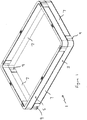
- a liner 1 for a manhole chamber comprising two stackable sections 3, 5 stacked one on top of the other.
- Each stackable section 3, 5 comprises four interconnected pieces 7, each piece being connected to an adjacent piece at their respective ends to form a substantially quadrilateral section.
- the two stackable sections 3, 5 are stacked such that the points of connection or joins 9 between the adjacent pieces 7 of the lower section 3 are offset relative to the joins of the upper section so that the upper and lower joins do not align. It is intended that this alternating joint arrangement be repeated for subsequent sections that may be stacked on top of the two shown in Figure 1 when forming a deeper liner 1.
- Each piece 7 is made from compression moulded glass fibre polyester resin material and comprises a long arm 11 and a short arm 13 which are arranged to be substantially perpendicular to one another.
- the two arms 11, 13 extend from a common point and each terminates at a free end 15, 17.
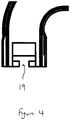
- the free end 15, 17 of each arm 11, 13 comprises a substantially vertical face into which is formed a T-shaped recess 19 which extends into the body of the arms 11, 13 from the respective faces.
- the pieces 7 are arranged such that when one face of one free end 15 of a piece 7 is arranged adjacent a face of a free end 17 of a corresponding piece 7 such that the two free ends interface, a H-shape is formed by the combined T-shaped recesses 19.
- a peg 20 having a profile which substantially matches the H-shape formed by the two recesses is provided which may be inserted into the H-shaped gap to hold the two pieces 7 together.
- the pieces 7 each comprise substantially flat, smooth inner 21 and outer skins 23 joined together by an upper web 25 that extends between and substantially at right angles to the inner and outer skins 21, 23 at their upper edges.
- An internal web 27 extends between the inner and outer skins along the arms of the piece 7 in a zigzag formation to improve sidewall loading and strengthen the piece 7.
- the short arm 13 of each piece 7 extends beyond a point of the inner skin 21 of the long arm to the short arm's free end 17 a distance which is greater than a width of the short arm 13.
- the length of the short arm 13 as measured along the longitudinal axis of the short arm 13 from a point of the inner skin 21 of the long arm 11 to the free end 17 of the short arm 13 combined with a length of the long arm 11 as measured along the longitudinal axis of the long arm 11 from a point of the inner skin 21 of the short arm 13 to the free end 15 of the long arm 11 is greater than the length l of the piece 7 as measured along the longitudinal axis of the long arm 11.
- a further corner piece 7 may be nested within the assembled section along the longitudinal axis of a long arm of a corner piece 7 as shown in Figures 6 and 7 .
- a plurality of different pieces 7 may be moulded having the above described features.
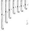
- the pieces 7 may differ as to the length of one of the arms x 1 , x 2 , x 3 , x 4 , x 5 , x 6 , x 7 , x n and remain constant as to the length of the other arm.
- a first range comprising seven different pieces 7 are provided whose long arms 11 are approximately 1820mm, 1420mm, 1120mm, 820mm, 720mm, 670mm and 520mm in length, respectively, as measured along the longitudinal axis of the long arm 11 from the inner skin 21 of the short arm 13 to the free end 15 of the long arm 11.
- each piece 7 is approximately 80mm in length as measured along the longitudinal axis of the short arm 13 from the inner skin 21 of the long arm 11 to the free end 17 of the short arm 13.
- a number of stackable sections 3, 5 can be assembled with differing dimensions by selecting the appropriate pieces 7. If it is desired to assemble a square section, four pieces 7 having the same length long arm 11 are chosen and connected together. If it is desired to assemble a rectangular section, a pair of pieces 7 whose long arms are the same length is connected to a pair of a pieces 7 whose long arms are the same as one another but different from the first pair.
- a second corresponding range of pieces 7 is also envisaged which is symmetrical with the above described first range about the longitudinal axis of the long arm 11.
- the symmetrical pieces permit the assembly of a stackable section whose joins 9 are offset relative to the joins 9 of a stackable section comprising pieces 7 from the first range.
- this permits a liner 1 to be constructed that comprises alternating stackable sections formed from the first range and second range, respectively, so that the joins 9 of each section do not align and extend upwardly along the entire height of the liner thereby creating a weak point.
- Different length straight pieces 29 are also provided which have corresponding T-shaped recesses formed in their free ends to enable them to be attached to the free ends of the corner pieces 7.
- the straight pieces 29 permit further variations of stackable sections to be assembled as desired without having to manufacture even longer corner pieces 7.
Landscapes
- Engineering & Computer Science (AREA)
- Environmental & Geological Engineering (AREA)
- Life Sciences & Earth Sciences (AREA)
- General Life Sciences & Earth Sciences (AREA)
- Mining & Mineral Resources (AREA)
- Paleontology (AREA)
- Civil Engineering (AREA)
- General Engineering & Computer Science (AREA)
- Structural Engineering (AREA)
- Underground Structures, Protecting, Testing And Restoring Foundations (AREA)
Description
- The present invention relates to a liner. The liner is particularly, but not exclusively intended for use in manhole chambers and the like.
- Liners are used to line a manhole chamber to provide a barrier between the space defined by the chamber and the surrounding earth. Liners of this general type are known. One such liner is disclosed in
EP0787861 which describes a liner comprising a number of stackable sections moulded from synthetic plastics materials. Each section comprises inner and outer skins joined together by two series of webs extending between and at right angles to the skins in the stacking direction. The sections are adapted to be stacked upon one another to permit the assembly of a corrosion resistant load bearing, rigid and deformation resisting structure. - A problem with the liner disclosed in
EP0787861 is that it is difficult to manufacture and assemble. A proposed improved chamber liner is described inGB-A-2 342 676 EP2622142 which discloses a liner comprising a number of stackable sections which are each comprised of separate connected pieces. The pieces are manufactured using a pultrusion technique. Whilst the liner can be broken down into smaller pieces for transportation purposes, the liner is difficult and costly to manufacture. - It is therefore an object of the present invention to provide an improved liner that is easy to manufacture, transport and assemble.
- According to a first aspect of the present invention, there is provided a piece for a stackable section used in a liner for a manhole chamber, the piece comprising a first arm and a second arm which are substantially perpendicular to one another, the first arm being longer than the second arm, wherein the first and second arms each comprise connection means to enable each arm to be connected to an adjacent arm of a corresponding piece and wherein the respective dimensions of the first arm and the second arm are chosen such that, when the piece is incorporated into a stackable section comprising three other corresponding pieces that are connected to each other in a sequence of a first arm of one piece connected to the second arm of an adjacent piece to form a quadrilateral stackable section, a further corresponding piece can fit within the stackable section along an axis substantially parallel to the longitudinal axis of the first arm.
- Advantageously, a number of pieces can be nested side by side within and across the width of a stackable section formed from four pieces. This maximises the number of pieces that can be transported in a given space and therefore minimises transportation costs. Further, a stackable section can be easily assembled from pieces according to the invention.
- The corresponding pieces may each comprise a first arm and a second arm which are substantially perpendicular to one another, the first arm being longer than the second arm, wherein the first and second arms each comprise connection means to enable each arm to be connected to an adjacent arm of a corresponding piece and wherein the respective dimensions of the first arm and the second arm are chosen such that, when the piece is incorporated into a stackable section comprising three other corresponding pieces that are connected to each other in a sequence of a first arm of one piece connected to the second arm of an adjacent piece to form a quadrilateral stackable section, a further corresponding piece can fit within the stackable section along an axis substantially parallel to the longitudinal axis of the first arm.
- The corresponding pieces may be identical to the piece of the first aspect of the invention.
- The first arm and the second arm may each comprise an inner skin and an outer skin and the second arm may extend beyond the inner skin of the first arm by a distance which is greater than a width across the short arm from its inner skin to its outer skin.
- The first arm and second arm may each comprise a free end. A length of the short arm as measured from the inner skin of the long arm to the free end of the short arm along the longitudinal axis of the short arm combined with a length of the long arm as measured from the inner skin of the short arm to the free end of the long arm along the longitudinal axis of the long arm may be greater than the length of the piece as measured from the free end of the long arm to the outer skin of the short arm along the longitudinal axis of the long arm.
- The inner and outer skins may be substantially flat.
- According to a second aspect of the present invention, there is provided a plurality of pieces according to the first aspect, wherein the length of each short arm of each piece is substantially the same and the length of the long arm of at least two pieces is different.
- According to a third aspect of the present invention, there is provided a plurality of pieces according to the first aspect comprising at least two pieces whose respective long arms are substantially the same length, wherein one of the two pieces is substantially symmetrical with the other of the two pieces.
- The symmetry may be about the longitudinal axis of the long arm, i.e. the two pieces may be mirror images of each other, in order to permit the assembly of a stackable section wherein joins between the plurality of corresponding pieces of one section are offset relative to the joins between the plurality of corresponding pieces of a section above and/or below.
- According to a fourth aspect of the present invention, there is provided a stackable section which may be stacked with other sections to form a liner for a manhole chamber, the stackable section comprising a pair of pieces according to the first aspect.
- The stackable section may comprise four pieces according to the first aspect.
- The short arm of each piece may be substantially the same length as the short arm of each other piece.
- The long arm of each piece may be substantially the same length as the long arm of each other piece.
- Where the stackable section comprises four pieces according to the first aspect, the long arms of two pieces may be a first length and the long arms of the other two pieces may be a second, different, length.
- According to a fifth aspect of the present invention, there is provided a liner for a manhole chamber comprising a plurality of pieces according to the third or fourth aspects.
- The liner may comprise a plurality of stackable sections, each stackable section formed from a plurality of pieces according to the first aspect of the invention joined together and one stackable section is stacked on top of another, wherein the joins of one section are offset relative to the other section on which it is stacked.
- In order that the invention may be more clearly understood an embodiment thereof will now be described, by way of example only, with reference to the accompanying drawings, of which:
- Figure 1
- is a perspective view of part of a liner for a chamber comprising pieces according to the invention;
- Figure 2a
- is a plan view of a piece incorporated into the liner shown in
Figure 1 ; - Figure 2b
- is a plan view of another piece incorporated into the liner shown in
Figure 1 ; - Figure 2c
- is an underside view of the piece shown in
Figure 2b ; - Figure 3
- is a plan view of a plurality of different pieces according to the invention;
- Figure 4
- is an enlarged cross section view of an end of the piece shown in
Figure 2c ; - Figure 5
- is an enlarged cross section view of the end of the piece shown in
Figure 4 arranged adjacent an end of another piece according to the invention; - Figure 6
- is a plan view of a stackable section comprising two pieces shown in
Figure 2a and two pieces shown inFigure 2b with a further piece as shown inFigure 2a nested within the section; - Figure 7
- is a plan view of the stackable section shown in
Figure 6 with a further piece as shown inFigure 2b nested within the section; and - Figure 8
- is a plan view of a plurality of straight pieces which may be connected to the pieces shown in
Figures 2a and 2b . - In the following the terms upward, upper, lower, inner, outer and like terms are used for convenience and refer to the stackable section and liner as shown oriented in the drawings, the orientation in which it is intended to be used, and should not be taken as otherwise limiting.
- With reference to the drawings there is shown a
liner 1 for a manhole chamber comprising twostackable sections stackable section interconnected pieces 7, each piece being connected to an adjacent piece at their respective ends to form a substantially quadrilateral section. The twostackable sections adjacent pieces 7 of thelower section 3 are offset relative to the joins of the upper section so that the upper and lower joins do not align. It is intended that this alternating joint arrangement be repeated for subsequent sections that may be stacked on top of the two shown inFigure 1 when forming adeeper liner 1. - Each
piece 7 is made from compression moulded glass fibre polyester resin material and comprises a long arm 11 and ashort arm 13 which are arranged to be substantially perpendicular to one another. The twoarms 11, 13 extend from a common point and each terminates at afree end free end arm 11, 13 comprises a substantially vertical face into which is formed a T-shaped recess 19 which extends into the body of thearms 11, 13 from the respective faces. Thepieces 7 are arranged such that when one face of onefree end 15 of apiece 7 is arranged adjacent a face of afree end 17 of acorresponding piece 7 such that the two free ends interface, a H-shape is formed by the combined T-shapedrecesses 19. Apeg 20 having a profile which substantially matches the H-shape formed by the two recesses is provided which may be inserted into the H-shaped gap to hold the twopieces 7 together. - The
pieces 7 each comprise substantially flat, smooth inner 21 andouter skins 23 joined together by anupper web 25 that extends between and substantially at right angles to the inner andouter skins internal web 27 extends between the inner and outer skins along the arms of thepiece 7 in a zigzag formation to improve sidewall loading and strengthen thepiece 7. - The
short arm 13 of eachpiece 7 extends beyond a point of theinner skin 21 of the long arm to the short arm's free end 17 a distance which is greater than a width of theshort arm 13. The length of theshort arm 13 as measured along the longitudinal axis of theshort arm 13 from a point of theinner skin 21 of the long arm 11 to thefree end 17 of theshort arm 13 combined with a length of the long arm 11 as measured along the longitudinal axis of the long arm 11 from a point of theinner skin 21 of theshort arm 13 to thefree end 15 of the long arm 11 is greater than the length l of thepiece 7 as measured along the longitudinal axis of the long arm 11. Thus, when a stackable section is assembled from fourcorresponding pieces 7, the internal width W or length L of the stackable section from a point of theinner skin 21 of one of thepieces 7 to a point of theinner skin 21 of thepiece 7 directly opposite is greater than the length l of thepiece 7 itself. Thus, afurther corner piece 7 may be nested within the assembled section along the longitudinal axis of a long arm of acorner piece 7 as shown inFigures 6 and7 . - A plurality of
different pieces 7 may be moulded having the above described features. Thepieces 7 may differ as to the length of one of the arms x1, x2, x3, x4, x5, x6, x7, xn and remain constant as to the length of the other arm. In this embodiment, a first range comprising sevendifferent pieces 7 are provided whose long arms 11 are approximately 1820mm, 1420mm, 1120mm, 820mm, 720mm, 670mm and 520mm in length, respectively, as measured along the longitudinal axis of the long arm 11 from theinner skin 21 of theshort arm 13 to thefree end 15 of the long arm 11. Theshort arm 13 of eachpiece 7 is approximately 80mm in length as measured along the longitudinal axis of theshort arm 13 from theinner skin 21 of the long arm 11 to thefree end 17 of theshort arm 13. Thus, a number ofstackable sections appropriate pieces 7. If it is desired to assemble a square section, fourpieces 7 having the same length long arm 11 are chosen and connected together. If it is desired to assemble a rectangular section, a pair ofpieces 7 whose long arms are the same length is connected to a pair of apieces 7 whose long arms are the same as one another but different from the first pair. - A second corresponding range of
pieces 7 is also envisaged which is symmetrical with the above described first range about the longitudinal axis of the long arm 11. The symmetrical pieces permit the assembly of a stackable section whose joins 9 are offset relative to the joins 9 of a stackablesection comprising pieces 7 from the first range. As described above, this permits aliner 1 to be constructed that comprises alternating stackable sections formed from the first range and second range, respectively, so that the joins 9 of each section do not align and extend upwardly along the entire height of the liner thereby creating a weak point. - Different length straight pieces 29 are also provided which have corresponding T-shaped recesses formed in their free ends to enable them to be attached to the free ends of the
corner pieces 7. The straight pieces 29 permit further variations of stackable sections to be assembled as desired without having to manufacture evenlonger corner pieces 7. - The above embodiment is described by way of example only. Many variations are possible without departing from the scope of the invention as defined in the appended claims.
Claims (13)
- A piece (7) for a stackable section (3, 5) used in a liner (1) for a manhole chamber, the piece comprising a first arm (11) and a second arm (13) which are substantially perpendicular to one another, the first arm (11) being longer than the second arm (13), wherein the first and second arms (11, 13) each comprise connection means (19) to enable each arm (11, 13) to be connected to an adjacent arm (11, 13) of a corresponding piece (7); wherein the first arm (11) and the second arm (13) each comprise an inner skin (21) and an outer skin (23) and characterised in that the second arm (13) extends beyond a region of the inner skin (21) of the first arm (11) by a distance which is greater than a width across the short arm (13) from its inner skin (21) to its outer skin (23); and the respective dimensions of the first arm (11) and the second arm (13 are chosen such that, when the piece (7) is incorporated into a stackable section (3, 5) comprising three other corresponding pieces (7) that are connected to each other in a sequence of a second arm (13) of one piece connected to the first arm (11) of an adjacent piece to form a quadrilateral stackable section (3, 5), a further corresponding piece (7) can fit within the stackable section (3, 5) along an axis substantially parallel to the longitudinal axis of the first arm (11).
- A piece (7) as claimed in claim 1, wherein the first arm (11) and second arm (13) each comprise a free end (15, 17).
- A piece (7) as claimed in claim 2, wherein a length of the short arm (13) as measured along the longitudinal axis of the short arm (13) from a point of the inner skin (21) of the long arm (11) to the free end (17) of the short arm combined with a length of the long arm (11) as measured along the longitudinal axis of the long arm (11) from a point of the inner skin (21) of the short arm (13) to the free end (15) of the long arm (11) is greater than the length of the piece (7) as measured along the longitudinal axis of the long arm (13).
- A plurality of pieces (7) as claimed in any of claims 1 to 3, wherein the length of each short arm (13) of each piece (7) is substantially the same and the length of the long arm (11) of at least two pieces (7) is different.
- A plurality of pieces (7) as claimed in any of claims 1 to 4, comprising at least two pieces (7) whose respective long arms (11) are substantially the same length, wherein one of the two pieces (7) is substantially symmetrical with the other of the two pieces (7).
- A plurality of pieces according to claim 5 wherein the symmetry is about the longitudinal axis of the long arm (11), such that the two pieces (7) are mirror images of each other, in order to permit the assembly of a stackable section (3, 5) wherein joins between the plurality of corresponding pieces (7) of one section (3, 5) are offset relative to the joins between the plurality of corresponding pieces (7) of a section (3, 5) above and/or below.
- A stackable section (3, 5) which may be stacked with other sections (3, 5) to form a liner (1) for a manhole chamber, the stackable section comprising a pair of pieces (7) as claimed in any of claims 1 to 6.
- A stackable section (3, 5) according to claim 7 comprising four pieces (7) according to any of claims 1 to 6.
- A stackable section (3, 5) as claimed in claim 7 or 8, wherein the short arm (13) of each piece (7) is substantially the same length as the short arm (7) of each other piece (7).
- A stackable section (3, 5) according to any of claims 7 to 9 wherein the long arm (11) of each piece (7) is substantially the same length as the long arm (11) of each other piece.
- A stackable section (3, 5) according to claim 8, or claim 9 when dependent on claim 8 wherein the long arms (11) of two pieces (7) are a first length and the long arms (11) of the two other pieces (7) are a second, different, length.
- A liner (1) for a manhole chamber comprising a plurality of pieces (7) according to claim 6, claim 7, or claim 8.
- A liner according to claim 12 comprising a plurality of stackable sections (3, 5), each stackable section (3, 5) formed from a plurality of pieces (7) according to any of claims 1 to 6 joined together and wherein one stackable section (3, 5) is stacked on top of another, wherein the joins of one section (3, 5) are offset relative to the other section (3, 5) on which it is stacked.
Applications Claiming Priority (2)
| Application Number | Priority Date | Filing Date | Title |
|---|---|---|---|
| GB1409133.4A GB2526343B (en) | 2014-05-22 | 2014-05-22 | A liner |
| PCT/GB2015/051507 WO2015177564A1 (en) | 2014-05-22 | 2015-05-21 | A liner |
Publications (2)
| Publication Number | Publication Date |
|---|---|
| EP3146113A1 EP3146113A1 (en) | 2017-03-29 |
| EP3146113B1 true EP3146113B1 (en) | 2019-10-16 |
Family
ID=51177297
Family Applications (1)
| Application Number | Title | Priority Date | Filing Date |
|---|---|---|---|
| EP15733481.4A Active EP3146113B1 (en) | 2014-05-22 | 2015-05-21 | A liner |
Country Status (5)
| Country | Link |
|---|---|
| US (1) | US10428487B2 (en) |
| EP (1) | EP3146113B1 (en) |
| AU (1) | AU2015263115B2 (en) |
| GB (1) | GB2526343B (en) |
| WO (1) | WO2015177564A1 (en) |
Families Citing this family (4)
| Publication number | Priority date | Publication date | Assignee | Title |
|---|---|---|---|---|
| DE102018101153A1 (en) * | 2018-01-19 | 2019-07-25 | Langmatz Gmbh | Frame for a cable duct |
| US11338524B1 (en) | 2018-10-26 | 2022-05-24 | Afl Telecommunications Llc | Method of forming a foldable or collapsible plastic and/or composite utility enclosure |
| US11374386B2 (en) | 2018-10-26 | 2022-06-28 | Afl Telecommunications Llc | Foldable and/or collapsible plastic/composite utility enclosure |
| US11349281B1 (en) | 2018-10-26 | 2022-05-31 | Afl Telecommunications Llc | Foldable and/or collapsible plastic/composite utility enclosure |
Family Cites Families (8)
| Publication number | Priority date | Publication date | Assignee | Title |
|---|---|---|---|---|
| GB9601530D0 (en) * | 1996-01-25 | 1996-03-27 | Valley Ind Ltd | A liner |
| US6195944B1 (en) * | 1998-06-02 | 2001-03-06 | Valley Industries Limited | Liner |
| GB2342676A (en) * | 1998-10-14 | 2000-04-19 | Radius Plastics Limited | Underground access chamber |
| EP1061183A3 (en) * | 1999-06-18 | 2001-03-14 | Swintex Limited | Improvements in or relating to underground junction boxes |
| ATE307229T1 (en) * | 2001-03-30 | 2005-11-15 | Carson Ind Ltd | UNDERGROUND SHAFT HOUSING |
| JP4515806B2 (en) * | 2004-04-22 | 2010-08-04 | 株式会社湘南合成樹脂製作所 | Rehabilitation of existing pipes |
| EP1916342A1 (en) * | 2006-10-25 | 2008-04-30 | Uponor Innovation Ab | Chamber riser |
| GB201016273D0 (en) * | 2010-09-28 | 2010-11-10 | Northstone Ni Ltd | A liner |
-
2014
- 2014-05-22 GB GB1409133.4A patent/GB2526343B/en active Active
-
2015
- 2015-05-21 US US15/313,438 patent/US10428487B2/en active Active
- 2015-05-21 WO PCT/GB2015/051507 patent/WO2015177564A1/en not_active Ceased
- 2015-05-21 AU AU2015263115A patent/AU2015263115B2/en active Active
- 2015-05-21 EP EP15733481.4A patent/EP3146113B1/en active Active
Non-Patent Citations (1)
| Title |
|---|
| None * |
Also Published As
| Publication number | Publication date |
|---|---|
| GB2526343A (en) | 2015-11-25 |
| AU2015263115A1 (en) | 2016-11-10 |
| US10428487B2 (en) | 2019-10-01 |
| US20170152642A1 (en) | 2017-06-01 |
| GB201409133D0 (en) | 2014-07-09 |
| AU2015263115B2 (en) | 2019-02-21 |
| EP3146113A1 (en) | 2017-03-29 |
| WO2015177564A1 (en) | 2015-11-26 |
| GB2526343B (en) | 2021-02-10 |
Similar Documents
| Publication | Publication Date | Title |
|---|---|---|
| US8286402B2 (en) | System of interlocking building blocks | |
| NL1040958B1 (en) | A plastic infiltration unit, a system comprising a plurality of plastic infiltration units. | |
| AU2015263115B2 (en) | A liner | |
| EP0452726A1 (en) | Panel structures formed by extrusion | |
| US10399739B2 (en) | Plastic pallet with stiffening structure | |
| US9592929B2 (en) | Dismantlable self-assembly structure | |
| BR112016028310B1 (en) | STRUCTURAL ELEMENT | |
| US11131113B2 (en) | Fence rail device | |
| US20100326334A1 (en) | Reinforced plastic pallet | |
| US20140120798A1 (en) | Stackable building block array | |
| US20080066404A1 (en) | Corner support | |
| US11267611B2 (en) | Pallet for carrying a load | |
| US9376811B2 (en) | Bar for a support structure for a false ceiling and production process for producing the bar | |
| US11028546B2 (en) | Concrete barrier-wall element and method of producing | |
| EP2622142B1 (en) | A liner for a manhole | |
| CN211341434U (en) | Card | |
| EP2759661B1 (en) | Modular tower | |
| KR20170051628A (en) | DIY Block And Structure Using The Same | |
| JP6796409B2 (en) | Foundation packing | |
| EP2664256A1 (en) | Reinforced metallic shelf for modular shelves structure | |
| JP6878830B2 (en) | Steel member manufacturing method | |
| EP3330454B1 (en) | Connection system and method for fitting floor covering modules together | |
| KR102884488B1 (en) | High load dry mezzanine system | |
| EP3153638A1 (en) | Building system based on plates of recycled material | |
| KR102214700B1 (en) | Variable side formwork |
Legal Events
| Date | Code | Title | Description |
|---|---|---|---|
| STAA | Information on the status of an ep patent application or granted ep patent |
Free format text: STATUS: THE INTERNATIONAL PUBLICATION HAS BEEN MADE |
|
| PUAI | Public reference made under article 153(3) epc to a published international application that has entered the european phase |
Free format text: ORIGINAL CODE: 0009012 |
|
| STAA | Information on the status of an ep patent application or granted ep patent |
Free format text: STATUS: REQUEST FOR EXAMINATION WAS MADE |
|
| 17P | Request for examination filed |
Effective date: 20161104 |
|
| AK | Designated contracting states |
Kind code of ref document: A1 Designated state(s): AL AT BE BG CH CY CZ DE DK EE ES FI FR GB GR HR HU IE IS IT LI LT LU LV MC MK MT NL NO PL PT RO RS SE SI SK SM TR |
|
| AX | Request for extension of the european patent |
Extension state: BA ME |
|
| DAV | Request for validation of the european patent (deleted) | ||
| DAX | Request for extension of the european patent (deleted) | ||
| STAA | Information on the status of an ep patent application or granted ep patent |
Free format text: STATUS: EXAMINATION IS IN PROGRESS |
|
| 17Q | First examination report despatched |
Effective date: 20180112 |
|
| GRAP | Despatch of communication of intention to grant a patent |
Free format text: ORIGINAL CODE: EPIDOSNIGR1 |
|
| STAA | Information on the status of an ep patent application or granted ep patent |
Free format text: STATUS: GRANT OF PATENT IS INTENDED |
|
| INTG | Intention to grant announced |
Effective date: 20190426 |
|
| GRAS | Grant fee paid |
Free format text: ORIGINAL CODE: EPIDOSNIGR3 |
|
| GRAA | (expected) grant |
Free format text: ORIGINAL CODE: 0009210 |
|
| STAA | Information on the status of an ep patent application or granted ep patent |
Free format text: STATUS: THE PATENT HAS BEEN GRANTED |
|
| AK | Designated contracting states |
Kind code of ref document: B1 Designated state(s): AL AT BE BG CH CY CZ DE DK EE ES FI FR GB GR HR HU IE IS IT LI LT LU LV MC MK MT NL NO PL PT RO RS SE SI SK SM TR |
|
| REG | Reference to a national code |
Ref country code: GB Ref legal event code: FG4D |
|
| REG | Reference to a national code |
Ref country code: CH Ref legal event code: EP |
|
| REG | Reference to a national code |
Ref country code: IE Ref legal event code: FG4D |
|
| REG | Reference to a national code |
Ref country code: DE Ref legal event code: R096 Ref document number: 602015039897 Country of ref document: DE |
|
| REG | Reference to a national code |
Ref country code: AT Ref legal event code: REF Ref document number: 1191373 Country of ref document: AT Kind code of ref document: T Effective date: 20191115 |
|
| REG | Reference to a national code |
Ref country code: NL Ref legal event code: MP Effective date: 20191016 |
|
| REG | Reference to a national code |
Ref country code: LT Ref legal event code: MG4D |
|
| REG | Reference to a national code |
Ref country code: AT Ref legal event code: MK05 Ref document number: 1191373 Country of ref document: AT Kind code of ref document: T Effective date: 20191016 |
|
| PG25 | Lapsed in a contracting state [announced via postgrant information from national office to epo] |
Ref country code: SE Free format text: LAPSE BECAUSE OF FAILURE TO SUBMIT A TRANSLATION OF THE DESCRIPTION OR TO PAY THE FEE WITHIN THE PRESCRIBED TIME-LIMIT Effective date: 20191016 Ref country code: LV Free format text: LAPSE BECAUSE OF FAILURE TO SUBMIT A TRANSLATION OF THE DESCRIPTION OR TO PAY THE FEE WITHIN THE PRESCRIBED TIME-LIMIT Effective date: 20191016 Ref country code: NO Free format text: LAPSE BECAUSE OF FAILURE TO SUBMIT A TRANSLATION OF THE DESCRIPTION OR TO PAY THE FEE WITHIN THE PRESCRIBED TIME-LIMIT Effective date: 20200116 Ref country code: PL Free format text: LAPSE BECAUSE OF FAILURE TO SUBMIT A TRANSLATION OF THE DESCRIPTION OR TO PAY THE FEE WITHIN THE PRESCRIBED TIME-LIMIT Effective date: 20191016 Ref country code: GR Free format text: LAPSE BECAUSE OF FAILURE TO SUBMIT A TRANSLATION OF THE DESCRIPTION OR TO PAY THE FEE WITHIN THE PRESCRIBED TIME-LIMIT Effective date: 20200117 Ref country code: FI Free format text: LAPSE BECAUSE OF FAILURE TO SUBMIT A TRANSLATION OF THE DESCRIPTION OR TO PAY THE FEE WITHIN THE PRESCRIBED TIME-LIMIT Effective date: 20191016 Ref country code: BG Free format text: LAPSE BECAUSE OF FAILURE TO SUBMIT A TRANSLATION OF THE DESCRIPTION OR TO PAY THE FEE WITHIN THE PRESCRIBED TIME-LIMIT Effective date: 20200116 Ref country code: PT Free format text: LAPSE BECAUSE OF FAILURE TO SUBMIT A TRANSLATION OF THE DESCRIPTION OR TO PAY THE FEE WITHIN THE PRESCRIBED TIME-LIMIT Effective date: 20200217 Ref country code: LT Free format text: LAPSE BECAUSE OF FAILURE TO SUBMIT A TRANSLATION OF THE DESCRIPTION OR TO PAY THE FEE WITHIN THE PRESCRIBED TIME-LIMIT Effective date: 20191016 Ref country code: NL Free format text: LAPSE BECAUSE OF FAILURE TO SUBMIT A TRANSLATION OF THE DESCRIPTION OR TO PAY THE FEE WITHIN THE PRESCRIBED TIME-LIMIT Effective date: 20191016 Ref country code: AT Free format text: LAPSE BECAUSE OF FAILURE TO SUBMIT A TRANSLATION OF THE DESCRIPTION OR TO PAY THE FEE WITHIN THE PRESCRIBED TIME-LIMIT Effective date: 20191016 |
|
| PG25 | Lapsed in a contracting state [announced via postgrant information from national office to epo] |
Ref country code: IS Free format text: LAPSE BECAUSE OF FAILURE TO SUBMIT A TRANSLATION OF THE DESCRIPTION OR TO PAY THE FEE WITHIN THE PRESCRIBED TIME-LIMIT Effective date: 20200224 Ref country code: HR Free format text: LAPSE BECAUSE OF FAILURE TO SUBMIT A TRANSLATION OF THE DESCRIPTION OR TO PAY THE FEE WITHIN THE PRESCRIBED TIME-LIMIT Effective date: 20191016 Ref country code: RS Free format text: LAPSE BECAUSE OF FAILURE TO SUBMIT A TRANSLATION OF THE DESCRIPTION OR TO PAY THE FEE WITHIN THE PRESCRIBED TIME-LIMIT Effective date: 20191016 |
|
| PG25 | Lapsed in a contracting state [announced via postgrant information from national office to epo] |
Ref country code: AL Free format text: LAPSE BECAUSE OF FAILURE TO SUBMIT A TRANSLATION OF THE DESCRIPTION OR TO PAY THE FEE WITHIN THE PRESCRIBED TIME-LIMIT Effective date: 20191016 |
|
| REG | Reference to a national code |
Ref country code: DE Ref legal event code: R097 Ref document number: 602015039897 Country of ref document: DE |
|
| PG2D | Information on lapse in contracting state deleted |
Ref country code: IS |
|
| PG25 | Lapsed in a contracting state [announced via postgrant information from national office to epo] |
Ref country code: RO Free format text: LAPSE BECAUSE OF FAILURE TO SUBMIT A TRANSLATION OF THE DESCRIPTION OR TO PAY THE FEE WITHIN THE PRESCRIBED TIME-LIMIT Effective date: 20191016 Ref country code: DK Free format text: LAPSE BECAUSE OF FAILURE TO SUBMIT A TRANSLATION OF THE DESCRIPTION OR TO PAY THE FEE WITHIN THE PRESCRIBED TIME-LIMIT Effective date: 20191016 Ref country code: EE Free format text: LAPSE BECAUSE OF FAILURE TO SUBMIT A TRANSLATION OF THE DESCRIPTION OR TO PAY THE FEE WITHIN THE PRESCRIBED TIME-LIMIT Effective date: 20191016 Ref country code: ES Free format text: LAPSE BECAUSE OF FAILURE TO SUBMIT A TRANSLATION OF THE DESCRIPTION OR TO PAY THE FEE WITHIN THE PRESCRIBED TIME-LIMIT Effective date: 20191016 Ref country code: CZ Free format text: LAPSE BECAUSE OF FAILURE TO SUBMIT A TRANSLATION OF THE DESCRIPTION OR TO PAY THE FEE WITHIN THE PRESCRIBED TIME-LIMIT Effective date: 20191016 Ref country code: IS Free format text: LAPSE BECAUSE OF FAILURE TO SUBMIT A TRANSLATION OF THE DESCRIPTION OR TO PAY THE FEE WITHIN THE PRESCRIBED TIME-LIMIT Effective date: 20200216 |
|
| PLBE | No opposition filed within time limit |
Free format text: ORIGINAL CODE: 0009261 |
|
| STAA | Information on the status of an ep patent application or granted ep patent |
Free format text: STATUS: NO OPPOSITION FILED WITHIN TIME LIMIT |
|
| PG25 | Lapsed in a contracting state [announced via postgrant information from national office to epo] |
Ref country code: SM Free format text: LAPSE BECAUSE OF FAILURE TO SUBMIT A TRANSLATION OF THE DESCRIPTION OR TO PAY THE FEE WITHIN THE PRESCRIBED TIME-LIMIT Effective date: 20191016 Ref country code: IT Free format text: LAPSE BECAUSE OF FAILURE TO SUBMIT A TRANSLATION OF THE DESCRIPTION OR TO PAY THE FEE WITHIN THE PRESCRIBED TIME-LIMIT Effective date: 20191016 Ref country code: SK Free format text: LAPSE BECAUSE OF FAILURE TO SUBMIT A TRANSLATION OF THE DESCRIPTION OR TO PAY THE FEE WITHIN THE PRESCRIBED TIME-LIMIT Effective date: 20191016 |
|
| 26N | No opposition filed |
Effective date: 20200717 |
|
| PGFP | Annual fee paid to national office [announced via postgrant information from national office to epo] |
Ref country code: IE Payment date: 20200819 Year of fee payment: 6 |
|
| PG25 | Lapsed in a contracting state [announced via postgrant information from national office to epo] |
Ref country code: SI Free format text: LAPSE BECAUSE OF FAILURE TO SUBMIT A TRANSLATION OF THE DESCRIPTION OR TO PAY THE FEE WITHIN THE PRESCRIBED TIME-LIMIT Effective date: 20191016 |
|
| PG25 | Lapsed in a contracting state [announced via postgrant information from national office to epo] |
Ref country code: MC Free format text: LAPSE BECAUSE OF FAILURE TO SUBMIT A TRANSLATION OF THE DESCRIPTION OR TO PAY THE FEE WITHIN THE PRESCRIBED TIME-LIMIT Effective date: 20191016 Ref country code: CH Free format text: LAPSE BECAUSE OF NON-PAYMENT OF DUE FEES Effective date: 20200531 Ref country code: LI Free format text: LAPSE BECAUSE OF NON-PAYMENT OF DUE FEES Effective date: 20200531 |
|
| REG | Reference to a national code |
Ref country code: BE Ref legal event code: MM Effective date: 20200531 |
|
| PG25 | Lapsed in a contracting state [announced via postgrant information from national office to epo] |
Ref country code: LU Free format text: LAPSE BECAUSE OF NON-PAYMENT OF DUE FEES Effective date: 20200521 |
|
| PG25 | Lapsed in a contracting state [announced via postgrant information from national office to epo] |
Ref country code: BE Free format text: LAPSE BECAUSE OF NON-PAYMENT OF DUE FEES Effective date: 20200531 |
|
| PG25 | Lapsed in a contracting state [announced via postgrant information from national office to epo] |
Ref country code: IE Free format text: LAPSE BECAUSE OF NON-PAYMENT OF DUE FEES Effective date: 20210521 |
|
| PG25 | Lapsed in a contracting state [announced via postgrant information from national office to epo] |
Ref country code: TR Free format text: LAPSE BECAUSE OF FAILURE TO SUBMIT A TRANSLATION OF THE DESCRIPTION OR TO PAY THE FEE WITHIN THE PRESCRIBED TIME-LIMIT Effective date: 20191016 Ref country code: MT Free format text: LAPSE BECAUSE OF FAILURE TO SUBMIT A TRANSLATION OF THE DESCRIPTION OR TO PAY THE FEE WITHIN THE PRESCRIBED TIME-LIMIT Effective date: 20191016 Ref country code: CY Free format text: LAPSE BECAUSE OF FAILURE TO SUBMIT A TRANSLATION OF THE DESCRIPTION OR TO PAY THE FEE WITHIN THE PRESCRIBED TIME-LIMIT Effective date: 20191016 |
|
| PG25 | Lapsed in a contracting state [announced via postgrant information from national office to epo] |
Ref country code: MK Free format text: LAPSE BECAUSE OF FAILURE TO SUBMIT A TRANSLATION OF THE DESCRIPTION OR TO PAY THE FEE WITHIN THE PRESCRIBED TIME-LIMIT Effective date: 20191016 |
|
| P01 | Opt-out of the competence of the unified patent court (upc) registered |
Effective date: 20230509 |
|
| REG | Reference to a national code |
Ref country code: GB Ref legal event code: 732E Free format text: REGISTERED BETWEEN 20230629 AND 20230705 |
|
| REG | Reference to a national code |
Ref country code: DE Ref legal event code: R081 Ref document number: 602015039897 Country of ref document: DE Owner name: CUBIS SYSTEMS LTD., GB Free format text: FORMER OWNER: NORTHSTONE (NI) LIMITED, DUNMURRY, BELFAST, GB |
|
| PGFP | Annual fee paid to national office [announced via postgrant information from national office to epo] |
Ref country code: DE Payment date: 20250519 Year of fee payment: 11 |
|
| PGFP | Annual fee paid to national office [announced via postgrant information from national office to epo] |
Ref country code: GB Payment date: 20260309 Year of fee payment: 12 |
|
| PGFP | Annual fee paid to national office [announced via postgrant information from national office to epo] |
Ref country code: FR Payment date: 20260309 Year of fee payment: 12 |