EP3145217A1 - Low-profile loudspeaker - Google Patents
Low-profile loudspeaker Download PDFInfo
- Publication number
- EP3145217A1 EP3145217A1 EP16189127.0A EP16189127A EP3145217A1 EP 3145217 A1 EP3145217 A1 EP 3145217A1 EP 16189127 A EP16189127 A EP 16189127A EP 3145217 A1 EP3145217 A1 EP 3145217A1
- Authority
- EP
- European Patent Office
- Prior art keywords
- loudspeaker
- support structure
- diaphragm
- loudspeaker according
- suspension
- Prior art date
- Legal status (The legal status is an assumption and is not a legal conclusion. Google has not performed a legal analysis and makes no representation as to the accuracy of the status listed.)
- Granted
Links
Images


Classifications
-
- H—ELECTRICITY
- H04—ELECTRIC COMMUNICATION TECHNIQUE
- H04R—LOUDSPEAKERS, MICROPHONES, GRAMOPHONE PICK-UPS OR LIKE ACOUSTIC ELECTROMECHANICAL TRANSDUCERS; ELECTRIC HEARING AIDS; PUBLIC ADDRESS SYSTEMS
- H04R9/00—Transducers of moving-coil, moving-strip, or moving-wire type
- H04R9/02—Details
- H04R9/04—Construction, mounting, or centering of coil
-
- H—ELECTRICITY
- H04—ELECTRIC COMMUNICATION TECHNIQUE
- H04R—LOUDSPEAKERS, MICROPHONES, GRAMOPHONE PICK-UPS OR LIKE ACOUSTIC ELECTROMECHANICAL TRANSDUCERS; ELECTRIC HEARING AIDS; PUBLIC ADDRESS SYSTEMS
- H04R9/00—Transducers of moving-coil, moving-strip, or moving-wire type
- H04R9/02—Details
-
- H—ELECTRICITY
- H04—ELECTRIC COMMUNICATION TECHNIQUE
- H04R—LOUDSPEAKERS, MICROPHONES, GRAMOPHONE PICK-UPS OR LIKE ACOUSTIC ELECTROMECHANICAL TRANSDUCERS; ELECTRIC HEARING AIDS; PUBLIC ADDRESS SYSTEMS
- H04R7/00—Diaphragms for electromechanical transducers; Cones
- H04R7/02—Diaphragms for electromechanical transducers; Cones characterised by the construction
-
- H—ELECTRICITY
- H04—ELECTRIC COMMUNICATION TECHNIQUE
- H04R—LOUDSPEAKERS, MICROPHONES, GRAMOPHONE PICK-UPS OR LIKE ACOUSTIC ELECTROMECHANICAL TRANSDUCERS; ELECTRIC HEARING AIDS; PUBLIC ADDRESS SYSTEMS
- H04R9/00—Transducers of moving-coil, moving-strip, or moving-wire type
- H04R9/02—Details
- H04R9/04—Construction, mounting, or centering of coil
- H04R9/041—Centering
- H04R9/043—Inner suspension or damper, e.g. spider
-
- H—ELECTRICITY
- H04—ELECTRIC COMMUNICATION TECHNIQUE
- H04R—LOUDSPEAKERS, MICROPHONES, GRAMOPHONE PICK-UPS OR LIKE ACOUSTIC ELECTROMECHANICAL TRANSDUCERS; ELECTRIC HEARING AIDS; PUBLIC ADDRESS SYSTEMS
- H04R9/00—Transducers of moving-coil, moving-strip, or moving-wire type
- H04R9/06—Loudspeakers
-
- H—ELECTRICITY
- H04—ELECTRIC COMMUNICATION TECHNIQUE
- H04R—LOUDSPEAKERS, MICROPHONES, GRAMOPHONE PICK-UPS OR LIKE ACOUSTIC ELECTROMECHANICAL TRANSDUCERS; ELECTRIC HEARING AIDS; PUBLIC ADDRESS SYSTEMS
- H04R2207/00—Details of diaphragms or cones for electromechanical transducers or their suspension covered by H04R7/00 but not provided for in H04R7/00 or in H04R2307/00
- H04R2207/021—Diaphragm extensions, not necessarily integrally formed, e.g. skirts, rims, flanges
-
- H—ELECTRICITY
- H04—ELECTRIC COMMUNICATION TECHNIQUE
- H04R—LOUDSPEAKERS, MICROPHONES, GRAMOPHONE PICK-UPS OR LIKE ACOUSTIC ELECTROMECHANICAL TRANSDUCERS; ELECTRIC HEARING AIDS; PUBLIC ADDRESS SYSTEMS
- H04R2400/00—Loudspeakers
- H04R2400/11—Aspects regarding the frame of loudspeaker transducers
-
- H—ELECTRICITY
- H04—ELECTRIC COMMUNICATION TECHNIQUE
- H04R—LOUDSPEAKERS, MICROPHONES, GRAMOPHONE PICK-UPS OR LIKE ACOUSTIC ELECTROMECHANICAL TRANSDUCERS; ELECTRIC HEARING AIDS; PUBLIC ADDRESS SYSTEMS
- H04R7/00—Diaphragms for electromechanical transducers; Cones
- H04R7/02—Diaphragms for electromechanical transducers; Cones characterised by the construction
- H04R7/12—Non-planar diaphragms or cones
- H04R7/14—Non-planar diaphragms or cones corrugated, pleated or ribbed
Definitions
- the present invention relates to the field of loudspeakers, and especially relates to diaphragms and to loudspeakers having diaphragms.
- a loudspeaker typically has a voice coil comprising a conductor through which a current may be passed, placed within a magnet assembly so that when current is passed through the voice coil an electromagnetic driving force is produced.
- This drives a driven body, such as a diaphragm.
- this vibrates along the loudspeaker axis (i.e. the axis which passes from a front to a rear of the loudspeaker and which is substantially central to the loudspeaker, around which the loudspeaker is usually substantially rotationally symmetric), driven by a driver mechanism such as a voice coil as described.
- the movement of the diaphragm creates a pressure wave in the surrounding air, which propagates as a sound wave.
- a loudspeaker diaphragm inevitably resonates at certain frequencies, the lowest of which is described in the art as a "breakup" frequency. Such resonances are generally undesirable, as they involve movements of the diaphragm that do not correspond to the electrical signal that is being applied via the voice coil. Thus, if they fall within the frequency range of the loudspeaker (or close to it) then they will affect the sound output. Generally, a stiff diaphragm will show resonance at a higher frequency, and efforts are often directed at increasing the stiffness of the diaphragm so that the resonant frequency is pushed to a higher level, allowing a higher frequency range for the loudspeaker.
- a concave cone diaphragm is commonly used as this combines a good surface area with an inherently stiff shape.
- a suspension is often attached to a rear face of the cone, and comprises a structure with a gentle elastic response in order to provide a restoring force to the diaphragm.
- the diaphragm is typically set within an elastically-deformable surround which encircles the diaphragm and connects its outer edge to a fixed support structure. This provides a further gentle restoring force, and also creates an air seal separating the air volumes in front of and behind the diaphragm. The latter prevents dissipation of the pressure wave created by movement of the diaphragm by air flow to or from the converse-pressure region behind the diaphragm.
- a simple cone shape may be impractical as it lends a significant depth to the loudspeaker.
- One such method is shown in US2010/0208934 and US2012/0106776 , and involves forming the diaphragm as a double cone, having a radially inner convex cone shape (as viewed from the exterior of the loudspeaker) and a radially outer concave cone shape. Viewed in section, the diaphragm thus adopts a "V" profile.
- the suspension is attached to the diaphragm at the apex of the V shape and the inner and outer edges of the V are attached to the voice coil and the surround respectively.
- Another solution is shown in our application GB2479941A , which describes a generally flat loudspeaker diaphragm with stiffening ribs projecting transversely away from a surface of the diaphragm.
- a key requirement of a loudspeaker with a shallow overall depth is the provision of a sufficient excursion capability, so that a sufficient volume of air can be moved by the loudspeaker to meet the requirements thereof. This is especially relevant when the loudspeaker is intended to be used to generate sound in the lower-frequency ranges.
- the present invention is directed to a loudspeaker, comprising a magnet structure, and a voice coil lying within a magnetic field established by the magnet structure and responsive to electrical signals to undergo excursions from a rest position along an axis of motion; a driven body, connected to the voice coil and moveable to project acoustic waves from a front of the loudspeaker; and a suspension for providing a restoring force to the driven body towards the rest position, the suspension extending from an attachment point on the driven body to an attachment point on a fixed portion of the loudspeaker; wherein the driven body comprises a diaphragm and a support structure extending rearwardly from a connection point with the voice coil to a connection point with the suspension located rearward of the frontal part of the magnet structure.
- the diaphragm of the present invention can be largely flat, or only mildly convex/concave, without a peak portion between its inner rim and outer rim as described in US2010/0208934 and US2012/0106776 .
- the shape for the connection point for the suspension is free and unconstrained by the design constraints on the diaphragm itself, and therefore an adequate surface area can be provided for an adhesive connection between the support structure and the suspension. This can be contrasted with US2010/0208934 and US2012/0106776 in which the suspension must be attached to an apex point in the V profile.
- An advantage of this arrangement is that it enables flexibility in positioning the support structure, so as to optimise heights for excursion clearances, for different sizes and preferred functions of loudspeakers.
- the support structure can also stiffen the driven body, while keeping its weight low. Such stiffening reduces undesirable resonances.
- the support structure may thus comprise a first conical portion extending rearwardly outwardly from the connection point with the voice coil to the connection point with the suspension.
- the diaphragm may be connected to the support structure at the connection point with the voice coil.
- the support structure may comprise a second conical portion extending forwardly outwardly from the connection point with the suspension.
- the two conical portions introduce a shape to the support structure which may be described as having two frusto-conical regions, arranged so that their would-be apexes are oriented to be rearward and frontward, with respect to the loudspeaker, respectively. Such an arrangement may also be described as being bi-conical.
- a yet further advantage of the loudspeaker of the present invention is that it may be assembled in a generally conventional manner, thus minimising any changes needed to the overall manufacturing processes.
- the diaphragm may be connected to the support structure at an outer region of the second conical portion.
- the diaphragm, first conical portion and second conical portion form (in section) a highly rigid triangular shape which has a high stiffness and an elevated breakup frequency.
- the loudspeaker may further comprise a flexible surround, attached to the support structure and/or the diaphragm at or near an outer region of the second conical portion.
- the support structure may have at least one transition portion between slanted portions, at which the suspension can conveniently be connected.
- a transition portion and the conical portions may thus form a substantially "U" shape.
- the support structure may have a plurality of apertures formed in its surface, to allow fluid communication between the interior space in front of the first and second conical portions and behind the rear face of the diaphragm. This establishes the volume within the support structure as part of the acoustic volume behind the diaphragm, thus reducing the acoustic impedance to movement of the diaphragm as described above. Reinforcing undulations can also be provided on the support structure, to increase its stiffness still further.
- the apertures and undulations are preferably combined into a single structure in the form of an aperture with a surrounding rib. They are ideally spaced substantially symmetrically around the diaphragm.
- the loudspeaker may further comprise a frame at a rear of the loudspeaker.
- FIG. 1 shows a loudspeaker 10 embodying the present invention.
- This has a magnet structure 12, of a conventional format.
- a permanent magnet 11 is held within a pair of pole pieces 8, 9 which are shaped to direct the magnetic flux and create a strong localised magnetic field across a short annular gap 13 between opposing faces of the pole pieces 8.
- a cylindrical voice coil former 14 lies within the magnetic field established in the gap 13 by the magnet structure 12, and carries a voice coil 15 which is then responsive to electrical signals to undergo excursions from a rest position along an axis of motion X.
- a driven body 16 is connected to the voice coil 14 and is moveable to project acoustic waves from a front F of the loudspeaker 10.
- a suspension 18 provides a restoring for to the driven body 16 towards the rest position, the suspension 18 extending from an attachment point 20 on the driven body 16 to an attachment point 22 on a fixed portion of the loudspeaker 10.
- the driven body 16 comprises a diaphragm 24 and a support structure 26; the support structure 26 extends rearwardly from a connection point 28 with the voice coil 14 to the connection point 20 with the suspension 18.
- the support structure 26 has a first conical portion 30 extending rearwardly outwardly from the connection point 16 with the voice coil 14, and a second conical portion 32 extending forwardly outwardly from the connection point 20 with the suspension.
- the support structure has a transition portion 34.
- the transition portion 34 is substantially perpendicular to the axis of motion X, when the loudspeaker 10 is in the rest position.
- the first conical portion 30, the second conical portion 32, and the transition portion 34 together form a U-shape.
- the diaphragm 24 extends across the front of the driven body 16 and is connected to the support structure 26 at the connection point 16 with the voice coil, and at an outer region 36 of the second conical portion 32.
- a flexible surround 38 is attached to the support structure 26 at an outer region 36 of the second conical portion 32.
- the diaphragm 24 is gently curved; this lends a generally flat profile to the frontal part of the loudspeaker and assists in creating a thin overall form factor.
- the diaphragm has a convex curve, i.e. creating a domed shape as viewed from the front of the loudspeaker, but other shapes are compatible with the present invention.
- the support structure 26 has undulations or ribs (not shown in Figure 1 ) formed therein for added stiffness, the ribs are spaced substantially symmetrically around the support structure 26. It also has apertures (not shown in figure 1 ) which allow air flow into and out of the enclosed region 44 between the diaphragm 24 and the support structure 26. This air flow can allow pressure differences resulting from ambient pressure changes to equalise, and (more importantly) means that the enclosed region 44 forms part of the acoustic volume behind the diaphragm 24. A large acoustic volume allows the movement of the diaphragm to be accommodated with less compression of the air within the volume, thereby reducing the acoustic impedance to movement of the diaphragm.
- the loudspeaker 10 also has a frame 42 at its rear which supports and houses the elements of the loudspeaker.
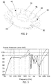
- Figure 2 shows the support structure 26 of figure 1 in more detail.
- the support structure 26 has a first conical section 30, a second conical section 32, and a transition portion 34 joining the two first 30 and second 32 conical sections.
- the support structure 26 has a U-shape.
- a plurality of structures 40 are symmetrically distributed around the support structure 26; each of these are in the form of an aperture 46 surrounded by an upstanding rib or ridge 48, to allow for fluid communication as noted above and also give added stiffness to the support structure.
- the described structure gives rise to the advantages set out above, in the form of a stiff diaphragm in a shallow structure, which is resistant to rocking motions.
- the spacing of the suspension and surround from the centre of the rotation and from each other results in a leverage which has the effect of magnifying the radial stiffness of the suspension and the surround.
- the magnitude of any rocking motion will be reduced, thereby reducing the likelihood of the coil touching the adjacent stationary structures and resulting in less distortion of the output and a reduced likelihood of failure.
- Figure 3 shows a comparison between a frequency response of a loudspeaker with a double-cone diaphragm, shown as a dashed line, and a frequency response of a loudspeaker embodying the present invention, having a diaphragm with a support structure, shown as a solid line. It can be seen that a better frequency response is provided; non-linearities in the achieved sound pressure are less significant and/or are moved to higher frequencies.
- FIG 4 shows a loudspeaker 10 embodying the present invention at a stage during its assembly process.
- the voice coil 14 and the support structure 26 have been pre-assembled as a unit and are being centralised in the magnetic field gap of the magnet structure 12 using a shim-type jig 100.
- the suspension 18 and the surround 38 can be fitted and adhered to the frame 42 to secure the support structure 26 and voice coil 14 in that location.
- jig 100 can be removed and the diaphragm 24 can be attached to the front of the support structure 26, for example by an adhesive attachment to the support structure 26.
- the loudspeaker 10 may be assembled in a generally conventional way.
Landscapes
- Engineering & Computer Science (AREA)
- Physics & Mathematics (AREA)
- Acoustics & Sound (AREA)
- Signal Processing (AREA)
- Multimedia (AREA)
- Audible-Bandwidth Dynamoelectric Transducers Other Than Pickups (AREA)
- Diaphragms For Electromechanical Transducers (AREA)
Abstract
Description
- The present invention relates to the field of loudspeakers, and especially relates to diaphragms and to loudspeakers having diaphragms.
- A loudspeaker typically has a voice coil comprising a conductor through which a current may be passed, placed within a magnet assembly so that when current is passed through the voice coil an electromagnetic driving force is produced. This in turn drives a driven body, such as a diaphragm. Conventionally, this vibrates along the loudspeaker axis (i.e. the axis which passes from a front to a rear of the loudspeaker and which is substantially central to the loudspeaker, around which the loudspeaker is usually substantially rotationally symmetric), driven by a driver mechanism such as a voice coil as described. The movement of the diaphragm creates a pressure wave in the surrounding air, which propagates as a sound wave.
- A loudspeaker diaphragm inevitably resonates at certain frequencies, the lowest of which is described in the art as a "breakup" frequency. Such resonances are generally undesirable, as they involve movements of the diaphragm that do not correspond to the electrical signal that is being applied via the voice coil. Thus, if they fall within the frequency range of the loudspeaker (or close to it) then they will affect the sound output. Generally, a stiff diaphragm will show resonance at a higher frequency, and efforts are often directed at increasing the stiffness of the diaphragm so that the resonant frequency is pushed to a higher level, allowing a higher frequency range for the loudspeaker. To this end, a concave cone diaphragm is commonly used as this combines a good surface area with an inherently stiff shape. A suspension is often attached to a rear face of the cone, and comprises a structure with a gentle elastic response in order to provide a restoring force to the diaphragm.
- The diaphragm is typically set within an elastically-deformable surround which encircles the diaphragm and connects its outer edge to a fixed support structure. This provides a further gentle restoring force, and also creates an air seal separating the air volumes in front of and behind the diaphragm. The latter prevents dissipation of the pressure wave created by movement of the diaphragm by air flow to or from the converse-pressure region behind the diaphragm.
- Where a loudspeaker is designed with a view to minimising its overall depth, such as where the available depth is at a premium, a simple cone shape may be impractical as it lends a significant depth to the loudspeaker. However, it remains important to maintain the stiffness of the diaphragm. Various options exist to cope with this challenge. One such method is shown in
US2010/0208934 andUS2012/0106776 , and involves forming the diaphragm as a double cone, having a radially inner convex cone shape (as viewed from the exterior of the loudspeaker) and a radially outer concave cone shape. Viewed in section, the diaphragm thus adopts a "V" profile. The suspension is attached to the diaphragm at the apex of the V shape and the inner and outer edges of the V are attached to the voice coil and the surround respectively. Another solution is shown in our applicationGB2479941A - A key requirement of a loudspeaker with a shallow overall depth is the provision of a sufficient excursion capability, so that a sufficient volume of air can be moved by the loudspeaker to meet the requirements thereof. This is especially relevant when the loudspeaker is intended to be used to generate sound in the lower-frequency ranges.
- It is also a challenge that a simple flat shallow diaphragm may suffer from "rocking" movements, i.e. rotational oscillations about an axis perpendicular to the loudspeaker axis. Rocking vibrations may become problematic if the suspension of the loudspeaker is arranged in a plane that is close to the plane of the surround, as the combined moment that can be exerted by the two restoring forces to counteract a rocking movement is small. A rocking movement can cause the voice coil to become misaligned within the magnet arrangement and may cause contact between them, leading to damage to the voice coil.
- Thus, it is an aim of the present invention to provide a loudspeaker which can be arranged to minimise its overall depth without incurring certain problems that arise from other known solutions to this this aim.
- Accordingly, the present invention is directed to a loudspeaker, comprising a magnet structure, and a voice coil lying within a magnetic field established by the magnet structure and responsive to electrical signals to undergo excursions from a rest position along an axis of motion; a driven body, connected to the voice coil and moveable to project acoustic waves from a front of the loudspeaker; and a suspension for providing a restoring force to the driven body towards the rest position, the suspension extending from an attachment point on the driven body to an attachment point on a fixed portion of the loudspeaker; wherein the driven body comprises a diaphragm and a support structure extending rearwardly from a connection point with the voice coil to a connection point with the suspension located rearward of the frontal part of the magnet structure.
- Thus, the diaphragm of the present invention can be largely flat, or only mildly convex/concave, without a peak portion between its inner rim and outer rim as described in
US2010/0208934 andUS2012/0106776 . This means that the acoustic volume behind the diaphragm is maintained instead of being reduced by the V profile, leading to less acoustic impedance to movement of the diaphragm. Further, the shape for the connection point for the suspension is free and unconstrained by the design constraints on the diaphragm itself, and therefore an adequate surface area can be provided for an adhesive connection between the support structure and the suspension. This can be contrasted withUS2010/0208934 andUS2012/0106776 in which the suspension must be attached to an apex point in the V profile. - In the present invention, unwanted rocking movement or vibration as described above is addressed via an arrangement wherein the suspension is attached via the support structure, and thus in a plane that is spaced away from the diaphragm. This means that the moment of the total restoring force exerted on the diaphragm can be enough to discourage rocking motions.
- An advantage of this arrangement is that it enables flexibility in positioning the support structure, so as to optimise heights for excursion clearances, for different sizes and preferred functions of loudspeakers.
- The support structure can also stiffen the driven body, while keeping its weight low. Such stiffening reduces undesirable resonances. The support structure may thus comprise a first conical portion extending rearwardly outwardly from the connection point with the voice coil to the connection point with the suspension. The diaphragm may be connected to the support structure at the connection point with the voice coil. Further, the support structure may comprise a second conical portion extending forwardly outwardly from the connection point with the suspension.
- The two conical portions introduce a shape to the support structure which may be described as having two frusto-conical regions, arranged so that their would-be apexes are oriented to be rearward and frontward, with respect to the loudspeaker, respectively. Such an arrangement may also be described as being bi-conical.
- A yet further advantage of the loudspeaker of the present invention is that it may be assembled in a generally conventional manner, thus minimising any changes needed to the overall manufacturing processes.
- The diaphragm may be connected to the support structure at an outer region of the second conical portion. In this way, the diaphragm, first conical portion and second conical portion form (in section) a highly rigid triangular shape which has a high stiffness and an elevated breakup frequency.
- The loudspeaker may further comprise a flexible surround, attached to the support structure and/or the diaphragm at or near an outer region of the second conical portion.
- The support structure may have at least one transition portion between slanted portions, at which the suspension can conveniently be connected. A transition portion and the conical portions may thus form a substantially "U" shape.
- The support structure may have a plurality of apertures formed in its surface, to allow fluid communication between the interior space in front of the first and second conical portions and behind the rear face of the diaphragm. This establishes the volume within the support structure as part of the acoustic volume behind the diaphragm, thus reducing the acoustic impedance to movement of the diaphragm as described above. Reinforcing undulations can also be provided on the support structure, to increase its stiffness still further. The apertures and undulations are preferably combined into a single structure in the form of an aperture with a surrounding rib. They are ideally spaced substantially symmetrically around the diaphragm.
- The loudspeaker may further comprise a frame at a rear of the loudspeaker.
- An embodiment of the present invention will now be described by way of example, with reference to the accompanying figures in which;
-
Figure 1 shows a section through a loudspeaker embodying the present invention; -
Figure 2 shows a diaphragm of a loudspeaker embodying the present invention in perspective; -
Figure 3 shows frequency response curves for comparison between a loudspeaker with a double-cone diaphragm such as disclosed byUS2010/0208934 , and a loudspeaker embodying the present invention having a diaphragm with a support structure; and -
Figure 4 shows a step of an assembly process of a loudspeaker embodying the present invention. -
Figure 1 shows aloudspeaker 10 embodying the present invention. This has amagnet structure 12, of a conventional format. Apermanent magnet 11 is held within a pair ofpole pieces annular gap 13 between opposing faces of thepole pieces 8. 9. A cylindrical voice coil former 14 lies within the magnetic field established in thegap 13 by themagnet structure 12, and carries avoice coil 15 which is then responsive to electrical signals to undergo excursions from a rest position along an axis of motion X. A drivenbody 16 is connected to thevoice coil 14 and is moveable to project acoustic waves from a front F of theloudspeaker 10. Asuspension 18 provides a restoring for to the drivenbody 16 towards the rest position, thesuspension 18 extending from anattachment point 20 on the drivenbody 16 to anattachment point 22 on a fixed portion of theloudspeaker 10. - The driven
body 16 comprises adiaphragm 24 and asupport structure 26; thesupport structure 26 extends rearwardly from aconnection point 28 with thevoice coil 14 to theconnection point 20 with thesuspension 18. Thesupport structure 26 has a firstconical portion 30 extending rearwardly outwardly from theconnection point 16 with thevoice coil 14, and a secondconical portion 32 extending forwardly outwardly from theconnection point 20 with the suspension. Between the firstconical portion 30 and the secondconical portion 32 and at theconnection point 20 with the suspension, the support structure has atransition portion 34. Thetransition portion 34 is substantially perpendicular to the axis of motion X, when theloudspeaker 10 is in the rest position. The firstconical portion 30, the secondconical portion 32, and thetransition portion 34 together form a U-shape. - The
diaphragm 24 extends across the front of the drivenbody 16 and is connected to thesupport structure 26 at theconnection point 16 with the voice coil, and at anouter region 36 of the secondconical portion 32. Aflexible surround 38 is attached to thesupport structure 26 at anouter region 36 of the secondconical portion 32. Thediaphragm 24 is gently curved; this lends a generally flat profile to the frontal part of the loudspeaker and assists in creating a thin overall form factor. In this case, the diaphragm has a convex curve, i.e. creating a domed shape as viewed from the front of the loudspeaker, but other shapes are compatible with the present invention. - The
support structure 26 has undulations or ribs (not shown inFigure 1 ) formed therein for added stiffness, the ribs are spaced substantially symmetrically around thesupport structure 26. It also has apertures (not shown infigure 1 ) which allow air flow into and out of theenclosed region 44 between thediaphragm 24 and thesupport structure 26. This air flow can allow pressure differences resulting from ambient pressure changes to equalise, and (more importantly) means that theenclosed region 44 forms part of the acoustic volume behind thediaphragm 24. A large acoustic volume allows the movement of the diaphragm to be accommodated with less compression of the air within the volume, thereby reducing the acoustic impedance to movement of the diaphragm. Theloudspeaker 10 also has aframe 42 at its rear which supports and houses the elements of the loudspeaker. -
Figure 2 shows thesupport structure 26 offigure 1 in more detail. Thesupport structure 26 has a firstconical section 30, a secondconical section 32, and atransition portion 34 joining the two first 30 and second 32 conical sections. Thus, thesupport structure 26 has a U-shape. A plurality ofstructures 40 are symmetrically distributed around thesupport structure 26; each of these are in the form of anaperture 46 surrounded by an upstanding rib orridge 48, to allow for fluid communication as noted above and also give added stiffness to the support structure. - Thus, the described structure gives rise to the advantages set out above, in the form of a stiff diaphragm in a shallow structure, which is resistant to rocking motions. The spacing of the suspension and surround from the centre of the rotation and from each other results in a leverage which has the effect of magnifying the radial stiffness of the suspension and the surround. As a result, the magnitude of any rocking motion will be reduced, thereby reducing the likelihood of the coil touching the adjacent stationary structures and resulting in less distortion of the output and a reduced likelihood of failure.
-
Figure 3 shows a comparison between a frequency response of a loudspeaker with a double-cone diaphragm, shown as a dashed line, and a frequency response of a loudspeaker embodying the present invention, having a diaphragm with a support structure, shown as a solid line. It can be seen that a better frequency response is provided; non-linearities in the achieved sound pressure are less significant and/or are moved to higher frequencies. -
Figure 4 shows aloudspeaker 10 embodying the present invention at a stage during its assembly process. Many of the features described above with respect toFigure 1 are present in this drawing, but are not labelled in order to aid clarity. Thevoice coil 14 and thesupport structure 26 have been pre-assembled as a unit and are being centralised in the magnetic field gap of themagnet structure 12 using a shim-type jig 100. With thesupport structure 26 andvoice coil 14 in the correct position, thesuspension 18 and thesurround 38 can be fitted and adhered to theframe 42 to secure thesupport structure 26 andvoice coil 14 in that location. Once this has been fitted,jig 100 can be removed and thediaphragm 24 can be attached to the front of thesupport structure 26, for example by an adhesive attachment to thesupport structure 26. As noted above, theloudspeaker 10 may be assembled in a generally conventional way. - It will of course be understood that many variations may be made to the above-described embodiment without departing from the scope of the present invention.
Claims (15)
- A loudspeaker, comprising:a magnet structure, and a voice coil lying within a magnetic field established by the magnet structure and responsive to electrical signals to undergo excursions from a rest position along an axis of motion;a driven body, connected to the voice coil and moveable to project acoustic waves from a front of the loudspeaker; anda suspension for providing a restoring force to the driven body towards the rest position, the suspension extending from an attachment point on the driven body to an attachment point on a fixed portion of the loudspeaker;wherein the driven body comprises a diaphragm and a support structure extending rearwardly from a connection point with the voice coil to a connection point with the suspension located rearward of the frontal part of the magnet structure.
- A loudspeaker according to claim 1, wherein the support structure comprises a first conical portion extending rearwardly outwardly from the connection point with the voice coil to the connection point with the suspension.
- A loudspeaker according to claim 1 or claim 2 wherein the diaphragm is connected to the support structure at the connection point with the voice coil.
- A loudspeaker according to any one of the preceding claims wherein the support structure comprises a second conical portion extending forwardly outwardly from the connection point with the suspension.
- A loudspeaker according to claim 4 in which the diaphragm is connected to the support structure at an outer region of the second conical portion.
- A loudspeaker according to claim 4 or claim 5 further comprising a flexible surround, attached to at least one of the support structure and the diaphragm at an outer region of the second conical portion.
- A loudspeaker according to any one of the preceding claims, wherein the support structure has at least one transition portion between slanted portions.
- A loudspeaker according to claim 7, wherein a transition portion and the conical portions form a substantially "U" shape.
- A loudspeaker according to claim 7 or claim 8, wherein the transition portion is substantially perpendicular to the axis of motion, when the loudspeaker is in the rest position.
- A loudspeaker according to any preceding claim, wherein the support structure has at least one aperture to allow fluid communication therethrough.
- A loudspeaker according to claim 10 in which the support structure has a plurality of apertures.
- A loudspeaker according to claim 11 in which the apertures are spaced substantially symmetrically around the support structure.
- A loudspeaker according to any preceding claim, wherein the support structure has a plurality of undulations formed in its surface.
- A loudspeaker according to claim 13, in which the undulations are spaced substantially symmetrically around the support structure.
- A loudspeaker according to any one of the preceding claims, further comprising a frame at a rear of the loudspeaker.
Applications Claiming Priority (1)
| Application Number | Priority Date | Filing Date | Title |
|---|---|---|---|
| GB1516479.1A GB2542382A (en) | 2015-09-17 | 2015-09-17 | Low-profile loudspeaker |
Publications (2)
| Publication Number | Publication Date |
|---|---|
| EP3145217A1 true EP3145217A1 (en) | 2017-03-22 |
| EP3145217B1 EP3145217B1 (en) | 2020-02-19 |
Family
ID=54544398
Family Applications (1)
| Application Number | Title | Priority Date | Filing Date |
|---|---|---|---|
| EP16189127.0A Active EP3145217B1 (en) | 2015-09-17 | 2016-09-16 | Low-profile loudspeaker |
Country Status (4)
| Country | Link |
|---|---|
| US (1) | US10034094B2 (en) |
| EP (1) | EP3145217B1 (en) |
| CN (1) | CN106550307B (en) |
| GB (1) | GB2542382A (en) |
Cited By (1)
| Publication number | Priority date | Publication date | Assignee | Title |
|---|---|---|---|---|
| CN113037904A (en) * | 2019-12-25 | 2021-06-25 | 华为技术有限公司 | Speaker module and electronic equipment |
Families Citing this family (8)
| Publication number | Priority date | Publication date | Assignee | Title |
|---|---|---|---|---|
| EP3388798A1 (en) * | 2017-04-10 | 2018-10-17 | ITT Manufacturing Enterprises LLC | Exact constraint magnetic mount for vibration sensing module |
| FR3087068B1 (en) * | 2018-10-08 | 2022-01-21 | Devialet | ELECTRODYNAMIC LOUDSPEAKER COMPRISING A MESH |
| US11381921B2 (en) * | 2018-10-30 | 2022-07-05 | Sound Solutions International Co., Ltd. | Electrodynamic acoustic transducer with improved suspension system |
| GB201907610D0 (en) * | 2019-05-29 | 2019-07-10 | Pss Belgium Nv | Loudspeaker |
| KR102625408B1 (en) * | 2019-08-17 | 2024-01-15 | 가부시키가이샤 사운드펀 | Speaker unit and speaker curved diaphragm |
| EP4062652A1 (en) | 2019-11-19 | 2022-09-28 | Dolby Laboratories Licensing Corporation | Acoustic transducer having drop ring connected at resonant node |
| GB202009203D0 (en) * | 2020-06-17 | 2020-07-29 | Pss Belgium Nv | Loudspeaker |
| US12069459B2 (en) * | 2020-10-19 | 2024-08-20 | Harman International Industries, Incorporated | Loudspeaker assembly with a separate voice coil assembly |
Citations (3)
| Publication number | Priority date | Publication date | Assignee | Title |
|---|---|---|---|---|
| EP0914020A2 (en) * | 1997-10-30 | 1999-05-06 | NOKIA TECHNOLOGY GmbH | Loudspeaker |
| US7433485B1 (en) * | 2008-01-07 | 2008-10-07 | Mitek Corp., Inc. | Shallow speaker |
| US20120106776A1 (en) * | 2010-11-02 | 2012-05-03 | Liu Chun I | Slim Speaker |
Family Cites Families (25)
| Publication number | Priority date | Publication date | Assignee | Title |
|---|---|---|---|---|
| JP4233061B2 (en) * | 1996-05-31 | 2009-03-04 | ピーエスエス・ベルギー・エヌブイ | Dynamic speaker and system including the speaker |
| JP3643855B2 (en) * | 1998-06-05 | 2005-04-27 | パイオニア株式会社 | Speaker device |
| US7225895B2 (en) * | 1998-11-30 | 2007-06-05 | Joseph Yaacoub Sahyoun | Audio speaker with wobble free voice coil movement |
| US7185735B2 (en) * | 1998-11-30 | 2007-03-06 | Joseph Yaacoub Sahyoun | Audio speaker with wobble free voice coil movement |
| US20040188175A1 (en) * | 1998-11-30 | 2004-09-30 | Sahyoun Joseph Yaacoub | Audio speaker with wobble free voice coil movement |
| JP3942813B2 (en) * | 2000-08-03 | 2007-07-11 | パイオニア株式会社 | Speaker and its assembling method |
| US6501844B2 (en) * | 2000-12-08 | 2002-12-31 | Jl Audio, Inc. | Loudspeaker and method of assembling same |
| DE10120281C1 (en) * | 2001-04-25 | 2002-12-05 | Harman Audio Electronic Sys | speaker |
| US7209570B2 (en) * | 2001-06-11 | 2007-04-24 | Matsushita Electric Industrial Co., Ltd. | Speaker |
| JP2004048494A (en) * | 2002-07-12 | 2004-02-12 | Pioneer Electronic Corp | Loudspeaker system and diaphragm for loudspeaker |
| WO2004019446A2 (en) * | 2002-08-21 | 2004-03-04 | Sahyoun Joseph Y | Audio radiator with radiator flexure minization and voice coil elastic anti-wobble members |
| JP3651470B2 (en) * | 2003-03-31 | 2005-05-25 | 松下電器産業株式会社 | Speaker |
| WO2005015950A1 (en) * | 2003-08-08 | 2005-02-17 | Koninklijke Philips Electronics N.V. | Loudspeaker with undulated membrane |
| JP2005252924A (en) * | 2004-03-08 | 2005-09-15 | Matsushita Electric Ind Co Ltd | Speaker |
| JP4447356B2 (en) * | 2004-03-19 | 2010-04-07 | パイオニア株式会社 | Speaker device |
| JP2005269331A (en) * | 2004-03-19 | 2005-09-29 | Pioneer Electronic Corp | Loudspeaker apparatus and manufacturing method thereof |
| WO2005099305A1 (en) * | 2004-03-31 | 2005-10-20 | Matsushita Electric Industrial Co., Ltd. | Speaker, module using the same, electronic equipment and device, and speaker producing method |
| JP4604609B2 (en) * | 2004-08-27 | 2011-01-05 | パナソニック株式会社 | Speaker |
| US7574013B2 (en) * | 2004-12-14 | 2009-08-11 | Panasonic Corporation | Speaker |
| JP4400439B2 (en) * | 2004-12-14 | 2010-01-20 | パナソニック株式会社 | Speaker |
| EP1727392A2 (en) * | 2005-05-25 | 2006-11-29 | Pioneer Corporation | Speaker apparatus |
| JP2007096619A (en) * | 2005-09-28 | 2007-04-12 | Matsushita Electric Ind Co Ltd | Speaker |
| JP4735306B2 (en) * | 2006-02-09 | 2011-07-27 | パナソニック株式会社 | Speaker |
| WO2007135745A1 (en) * | 2006-05-24 | 2007-11-29 | Pioneer Corporation | Speaker device |
| US8204269B2 (en) * | 2008-08-08 | 2012-06-19 | Sahyoun Joseph Y | Low profile audio speaker with minimization of voice coil wobble, protection and cooling |
-
2015
- 2015-09-17 GB GB1516479.1A patent/GB2542382A/en not_active Withdrawn
-
2016
- 2016-09-14 CN CN201610823413.9A patent/CN106550307B/en active Active
- 2016-09-16 EP EP16189127.0A patent/EP3145217B1/en active Active
- 2016-09-16 US US15/267,596 patent/US10034094B2/en active Active
Patent Citations (3)
| Publication number | Priority date | Publication date | Assignee | Title |
|---|---|---|---|---|
| EP0914020A2 (en) * | 1997-10-30 | 1999-05-06 | NOKIA TECHNOLOGY GmbH | Loudspeaker |
| US7433485B1 (en) * | 2008-01-07 | 2008-10-07 | Mitek Corp., Inc. | Shallow speaker |
| US20120106776A1 (en) * | 2010-11-02 | 2012-05-03 | Liu Chun I | Slim Speaker |
Cited By (1)
| Publication number | Priority date | Publication date | Assignee | Title |
|---|---|---|---|---|
| CN113037904A (en) * | 2019-12-25 | 2021-06-25 | 华为技术有限公司 | Speaker module and electronic equipment |
Also Published As
| Publication number | Publication date |
|---|---|
| GB2542382A (en) | 2017-03-22 |
| US10034094B2 (en) | 2018-07-24 |
| GB201516479D0 (en) | 2015-11-04 |
| CN106550307B (en) | 2021-02-05 |
| CN106550307A (en) | 2017-03-29 |
| EP3145217B1 (en) | 2020-02-19 |
| US20170085993A1 (en) | 2017-03-23 |
Similar Documents
| Publication | Publication Date | Title |
|---|---|---|
| EP3145217B1 (en) | Low-profile loudspeaker | |
| CN110603816B (en) | Speaker unit having electromagnetic speaker and micro speaker | |
| US8290199B2 (en) | Loudspeaker suspension | |
| EP2321976B1 (en) | Nested compound loudspeaker drive unit | |
| EP1020096B1 (en) | Miniature full range loudspeaker | |
| EP2297975B1 (en) | Improved acoustic device | |
| EP2999239B1 (en) | Speaker | |
| EP3383060A1 (en) | Speaker device | |
| EP3203758B1 (en) | Electroacoustic transducer | |
| US7711138B2 (en) | Loudspeaker including a cone circumscribed by a stiffener | |
| US10820111B2 (en) | Acoustic membrane for a loudspeaker and corresponding loudspeaker | |
| JP6253101B2 (en) | Electrodynamic electroacoustic transducer, diaphragm thereof, and method for producing electrodynamic electroacoustic transducer | |
| HK1235956A1 (en) | Low-profile loudspeaker | |
| US20220236460A1 (en) | Diaphragm structure | |
| JPH05316590A (en) | Elliptic speaker | |
| US8009858B2 (en) | Loudspeaker | |
| CN107005765B (en) | Diaphragm for a loudspeaker device | |
| HK1235956B (en) | Low-profile loudspeaker | |
| KR20260009892A (en) | loudspeaker drive unit | |
| JP2006129111A (en) | Loudspeaker and diaphragm therefor | |
| JPH09312897A (en) | Electroacoustic transducer | |
| KR20220105796A (en) | The thin speaker | |
| HK1155882A (en) | Improved acoustic device | |
| HK1155882B (en) | Improved acoustic device |
Legal Events
| Date | Code | Title | Description |
|---|---|---|---|
| PUAI | Public reference made under article 153(3) epc to a published international application that has entered the european phase |
Free format text: ORIGINAL CODE: 0009012 |
|
| STAA | Information on the status of an ep patent application or granted ep patent |
Free format text: STATUS: THE APPLICATION HAS BEEN PUBLISHED |
|
| AK | Designated contracting states |
Kind code of ref document: A1 Designated state(s): AL AT BE BG CH CY CZ DE DK EE ES FI FR GB GR HR HU IE IS IT LI LT LU LV MC MK MT NL NO PL PT RO RS SE SI SK SM TR |
|
| AX | Request for extension of the european patent |
Extension state: BA ME |
|
| STAA | Information on the status of an ep patent application or granted ep patent |
Free format text: STATUS: REQUEST FOR EXAMINATION WAS MADE |
|
| 17P | Request for examination filed |
Effective date: 20170821 |
|
| RBV | Designated contracting states (corrected) |
Designated state(s): AL AT BE BG CH CY CZ DE DK EE ES FI FR GB GR HR HU IE IS IT LI LT LU LV MC MK MT NL NO PL PT RO RS SE SI SK SM TR |
|
| STAA | Information on the status of an ep patent application or granted ep patent |
Free format text: STATUS: EXAMINATION IS IN PROGRESS |
|
| 17Q | First examination report despatched |
Effective date: 20180214 |
|
| GRAP | Despatch of communication of intention to grant a patent |
Free format text: ORIGINAL CODE: EPIDOSNIGR1 |
|
| STAA | Information on the status of an ep patent application or granted ep patent |
Free format text: STATUS: GRANT OF PATENT IS INTENDED |
|
| RIC1 | Information provided on ipc code assigned before grant |
Ipc: H04R 7/02 20060101AFI20190829BHEP Ipc: H04R 9/06 20060101ALI20190829BHEP Ipc: H04R 9/04 20060101ALI20190829BHEP Ipc: H04R 7/14 20060101ALN20190829BHEP |
|
| RIC1 | Information provided on ipc code assigned before grant |
Ipc: H04R 9/04 20060101ALI20190902BHEP Ipc: H04R 9/06 20060101ALI20190902BHEP Ipc: H04R 7/14 20060101ALN20190902BHEP Ipc: H04R 7/02 20060101AFI20190902BHEP |
|
| INTG | Intention to grant announced |
Effective date: 20190919 |
|
| GRAS | Grant fee paid |
Free format text: ORIGINAL CODE: EPIDOSNIGR3 |
|
| GRAA | (expected) grant |
Free format text: ORIGINAL CODE: 0009210 |
|
| STAA | Information on the status of an ep patent application or granted ep patent |
Free format text: STATUS: THE PATENT HAS BEEN GRANTED |
|
| AK | Designated contracting states |
Kind code of ref document: B1 Designated state(s): AL AT BE BG CH CY CZ DE DK EE ES FI FR GB GR HR HU IE IS IT LI LT LU LV MC MK MT NL NO PL PT RO RS SE SI SK SM TR |
|
| REG | Reference to a national code |
Ref country code: CH Ref legal event code: EP |
|
| REG | Reference to a national code |
Ref country code: DE Ref legal event code: R096 Ref document number: 602016029957 Country of ref document: DE |
|
| REG | Reference to a national code |
Ref country code: AT Ref legal event code: REF Ref document number: 1236344 Country of ref document: AT Kind code of ref document: T Effective date: 20200315 |
|
| REG | Reference to a national code |
Ref country code: IE Ref legal event code: FG4D |
|
| REG | Reference to a national code |
Ref country code: NL Ref legal event code: MP Effective date: 20200219 |
|
| PG25 | Lapsed in a contracting state [announced via postgrant information from national office to epo] |
Ref country code: RS Free format text: LAPSE BECAUSE OF FAILURE TO SUBMIT A TRANSLATION OF THE DESCRIPTION OR TO PAY THE FEE WITHIN THE PRESCRIBED TIME-LIMIT Effective date: 20200219 Ref country code: NO Free format text: LAPSE BECAUSE OF FAILURE TO SUBMIT A TRANSLATION OF THE DESCRIPTION OR TO PAY THE FEE WITHIN THE PRESCRIBED TIME-LIMIT Effective date: 20200519 Ref country code: FI Free format text: LAPSE BECAUSE OF FAILURE TO SUBMIT A TRANSLATION OF THE DESCRIPTION OR TO PAY THE FEE WITHIN THE PRESCRIBED TIME-LIMIT Effective date: 20200219 |
|
| REG | Reference to a national code |
Ref country code: LT Ref legal event code: MG4D |
|
| PG25 | Lapsed in a contracting state [announced via postgrant information from national office to epo] |
Ref country code: SE Free format text: LAPSE BECAUSE OF FAILURE TO SUBMIT A TRANSLATION OF THE DESCRIPTION OR TO PAY THE FEE WITHIN THE PRESCRIBED TIME-LIMIT Effective date: 20200219 Ref country code: LV Free format text: LAPSE BECAUSE OF FAILURE TO SUBMIT A TRANSLATION OF THE DESCRIPTION OR TO PAY THE FEE WITHIN THE PRESCRIBED TIME-LIMIT Effective date: 20200219 Ref country code: HR Free format text: LAPSE BECAUSE OF FAILURE TO SUBMIT A TRANSLATION OF THE DESCRIPTION OR TO PAY THE FEE WITHIN THE PRESCRIBED TIME-LIMIT Effective date: 20200219 Ref country code: GR Free format text: LAPSE BECAUSE OF FAILURE TO SUBMIT A TRANSLATION OF THE DESCRIPTION OR TO PAY THE FEE WITHIN THE PRESCRIBED TIME-LIMIT Effective date: 20200520 Ref country code: IS Free format text: LAPSE BECAUSE OF FAILURE TO SUBMIT A TRANSLATION OF THE DESCRIPTION OR TO PAY THE FEE WITHIN THE PRESCRIBED TIME-LIMIT Effective date: 20200619 Ref country code: BG Free format text: LAPSE BECAUSE OF FAILURE TO SUBMIT A TRANSLATION OF THE DESCRIPTION OR TO PAY THE FEE WITHIN THE PRESCRIBED TIME-LIMIT Effective date: 20200519 |
|
| PG25 | Lapsed in a contracting state [announced via postgrant information from national office to epo] |
Ref country code: NL Free format text: LAPSE BECAUSE OF FAILURE TO SUBMIT A TRANSLATION OF THE DESCRIPTION OR TO PAY THE FEE WITHIN THE PRESCRIBED TIME-LIMIT Effective date: 20200219 |
|
| PG25 | Lapsed in a contracting state [announced via postgrant information from national office to epo] |
Ref country code: PT Free format text: LAPSE BECAUSE OF FAILURE TO SUBMIT A TRANSLATION OF THE DESCRIPTION OR TO PAY THE FEE WITHIN THE PRESCRIBED TIME-LIMIT Effective date: 20200712 Ref country code: SK Free format text: LAPSE BECAUSE OF FAILURE TO SUBMIT A TRANSLATION OF THE DESCRIPTION OR TO PAY THE FEE WITHIN THE PRESCRIBED TIME-LIMIT Effective date: 20200219 Ref country code: RO Free format text: LAPSE BECAUSE OF FAILURE TO SUBMIT A TRANSLATION OF THE DESCRIPTION OR TO PAY THE FEE WITHIN THE PRESCRIBED TIME-LIMIT Effective date: 20200219 Ref country code: CZ Free format text: LAPSE BECAUSE OF FAILURE TO SUBMIT A TRANSLATION OF THE DESCRIPTION OR TO PAY THE FEE WITHIN THE PRESCRIBED TIME-LIMIT Effective date: 20200219 Ref country code: LT Free format text: LAPSE BECAUSE OF FAILURE TO SUBMIT A TRANSLATION OF THE DESCRIPTION OR TO PAY THE FEE WITHIN THE PRESCRIBED TIME-LIMIT Effective date: 20200219 Ref country code: ES Free format text: LAPSE BECAUSE OF FAILURE TO SUBMIT A TRANSLATION OF THE DESCRIPTION OR TO PAY THE FEE WITHIN THE PRESCRIBED TIME-LIMIT Effective date: 20200219 Ref country code: DK Free format text: LAPSE BECAUSE OF FAILURE TO SUBMIT A TRANSLATION OF THE DESCRIPTION OR TO PAY THE FEE WITHIN THE PRESCRIBED TIME-LIMIT Effective date: 20200219 Ref country code: EE Free format text: LAPSE BECAUSE OF FAILURE TO SUBMIT A TRANSLATION OF THE DESCRIPTION OR TO PAY THE FEE WITHIN THE PRESCRIBED TIME-LIMIT Effective date: 20200219 Ref country code: SM Free format text: LAPSE BECAUSE OF FAILURE TO SUBMIT A TRANSLATION OF THE DESCRIPTION OR TO PAY THE FEE WITHIN THE PRESCRIBED TIME-LIMIT Effective date: 20200219 |
|
| REG | Reference to a national code |
Ref country code: AT Ref legal event code: MK05 Ref document number: 1236344 Country of ref document: AT Kind code of ref document: T Effective date: 20200219 |
|
| REG | Reference to a national code |
Ref country code: DE Ref legal event code: R097 Ref document number: 602016029957 Country of ref document: DE |
|
| PLBE | No opposition filed within time limit |
Free format text: ORIGINAL CODE: 0009261 |
|
| STAA | Information on the status of an ep patent application or granted ep patent |
Free format text: STATUS: NO OPPOSITION FILED WITHIN TIME LIMIT |
|
| 26N | No opposition filed |
Effective date: 20201120 |
|
| PG25 | Lapsed in a contracting state [announced via postgrant information from national office to epo] |
Ref country code: IT Free format text: LAPSE BECAUSE OF FAILURE TO SUBMIT A TRANSLATION OF THE DESCRIPTION OR TO PAY THE FEE WITHIN THE PRESCRIBED TIME-LIMIT Effective date: 20200219 Ref country code: AT Free format text: LAPSE BECAUSE OF FAILURE TO SUBMIT A TRANSLATION OF THE DESCRIPTION OR TO PAY THE FEE WITHIN THE PRESCRIBED TIME-LIMIT Effective date: 20200219 |
|
| PG25 | Lapsed in a contracting state [announced via postgrant information from national office to epo] |
Ref country code: SI Free format text: LAPSE BECAUSE OF FAILURE TO SUBMIT A TRANSLATION OF THE DESCRIPTION OR TO PAY THE FEE WITHIN THE PRESCRIBED TIME-LIMIT Effective date: 20200219 Ref country code: PL Free format text: LAPSE BECAUSE OF FAILURE TO SUBMIT A TRANSLATION OF THE DESCRIPTION OR TO PAY THE FEE WITHIN THE PRESCRIBED TIME-LIMIT Effective date: 20200219 |
|
| PG25 | Lapsed in a contracting state [announced via postgrant information from national office to epo] |
Ref country code: MC Free format text: LAPSE BECAUSE OF FAILURE TO SUBMIT A TRANSLATION OF THE DESCRIPTION OR TO PAY THE FEE WITHIN THE PRESCRIBED TIME-LIMIT Effective date: 20200219 |
|
| REG | Reference to a national code |
Ref country code: CH Ref legal event code: PL |
|
| REG | Reference to a national code |
Ref country code: BE Ref legal event code: MM Effective date: 20200930 |
|
| PG25 | Lapsed in a contracting state [announced via postgrant information from national office to epo] |
Ref country code: LU Free format text: LAPSE BECAUSE OF NON-PAYMENT OF DUE FEES Effective date: 20200916 |
|
| PG25 | Lapsed in a contracting state [announced via postgrant information from national office to epo] |
Ref country code: CH Free format text: LAPSE BECAUSE OF NON-PAYMENT OF DUE FEES Effective date: 20200930 Ref country code: BE Free format text: LAPSE BECAUSE OF NON-PAYMENT OF DUE FEES Effective date: 20200930 Ref country code: IE Free format text: LAPSE BECAUSE OF NON-PAYMENT OF DUE FEES Effective date: 20200916 Ref country code: LI Free format text: LAPSE BECAUSE OF NON-PAYMENT OF DUE FEES Effective date: 20200930 |
|
| PG25 | Lapsed in a contracting state [announced via postgrant information from national office to epo] |
Ref country code: TR Free format text: LAPSE BECAUSE OF FAILURE TO SUBMIT A TRANSLATION OF THE DESCRIPTION OR TO PAY THE FEE WITHIN THE PRESCRIBED TIME-LIMIT Effective date: 20200219 Ref country code: MT Free format text: LAPSE BECAUSE OF FAILURE TO SUBMIT A TRANSLATION OF THE DESCRIPTION OR TO PAY THE FEE WITHIN THE PRESCRIBED TIME-LIMIT Effective date: 20200219 Ref country code: CY Free format text: LAPSE BECAUSE OF FAILURE TO SUBMIT A TRANSLATION OF THE DESCRIPTION OR TO PAY THE FEE WITHIN THE PRESCRIBED TIME-LIMIT Effective date: 20200219 |
|
| PG25 | Lapsed in a contracting state [announced via postgrant information from national office to epo] |
Ref country code: MK Free format text: LAPSE BECAUSE OF FAILURE TO SUBMIT A TRANSLATION OF THE DESCRIPTION OR TO PAY THE FEE WITHIN THE PRESCRIBED TIME-LIMIT Effective date: 20200219 Ref country code: AL Free format text: LAPSE BECAUSE OF FAILURE TO SUBMIT A TRANSLATION OF THE DESCRIPTION OR TO PAY THE FEE WITHIN THE PRESCRIBED TIME-LIMIT Effective date: 20200219 |
|
| PGFP | Annual fee paid to national office [announced via postgrant information from national office to epo] |
Ref country code: DE Payment date: 20250714 Year of fee payment: 10 |
|
| PGFP | Annual fee paid to national office [announced via postgrant information from national office to epo] |
Ref country code: GB Payment date: 20250701 Year of fee payment: 10 |
|
| PGFP | Annual fee paid to national office [announced via postgrant information from national office to epo] |
Ref country code: FR Payment date: 20250714 Year of fee payment: 10 |