EP3145195A1 - An apparatus and a method for encoding an image captured by an optical acquisition system - Google Patents
An apparatus and a method for encoding an image captured by an optical acquisition system Download PDFInfo
- Publication number
- EP3145195A1 EP3145195A1 EP15306444.9A EP15306444A EP3145195A1 EP 3145195 A1 EP3145195 A1 EP 3145195A1 EP 15306444 A EP15306444 A EP 15306444A EP 3145195 A1 EP3145195 A1 EP 3145195A1
- Authority
- EP
- European Patent Office
- Prior art keywords
- acquisition system
- optical acquisition
- pixel
- parameters
- pupil
- Prior art date
- Legal status (The legal status is an assumption and is not a legal conclusion. Google has not performed a legal analysis and makes no representation as to the accuracy of the status listed.)
- Withdrawn
Links
- 230000003287 optical effect Effects 0.000 title claims abstract description 158
- 238000000034 method Methods 0.000 title claims description 31
- 238000012545 processing Methods 0.000 claims abstract description 33
- 210000001747 pupil Anatomy 0.000 claims description 60
- 230000008569 process Effects 0.000 claims description 13
- 238000005070 sampling Methods 0.000 claims description 9
- 230000001419 dependent effect Effects 0.000 claims description 4
- 238000004590 computer program Methods 0.000 claims description 2
- 238000003491 array Methods 0.000 abstract description 2
- 230000005540 biological transmission Effects 0.000 abstract description 2
- 230000006872 improvement Effects 0.000 abstract description 2
- 238000010586 diagram Methods 0.000 description 6
- 238000004891 communication Methods 0.000 description 3
- 230000009471 action Effects 0.000 description 2
- 239000000470 constituent Substances 0.000 description 2
- 230000006870 function Effects 0.000 description 2
- 238000012986 modification Methods 0.000 description 2
- 230000004048 modification Effects 0.000 description 2
- 239000004065 semiconductor Substances 0.000 description 2
- 230000035945 sensitivity Effects 0.000 description 2
- 238000010207 Bayesian analysis Methods 0.000 description 1
- 230000000295 complement effect Effects 0.000 description 1
- 238000005516 engineering process Methods 0.000 description 1
- 238000003384 imaging method Methods 0.000 description 1
- 238000012805 post-processing Methods 0.000 description 1
- 238000004321 preservation Methods 0.000 description 1
- 230000001902 propagating effect Effects 0.000 description 1
- 238000009877 rendering Methods 0.000 description 1
- 238000011160 research Methods 0.000 description 1
- 238000010008 shearing Methods 0.000 description 1
- 239000007787 solid Substances 0.000 description 1
- 238000010408 sweeping Methods 0.000 description 1
- 230000001052 transient effect Effects 0.000 description 1
Images


Classifications
-
- H—ELECTRICITY
- H04—ELECTRIC COMMUNICATION TECHNIQUE
- H04N—PICTORIAL COMMUNICATION, e.g. TELEVISION
- H04N19/00—Methods or arrangements for coding, decoding, compressing or decompressing digital video signals
- H04N19/50—Methods or arrangements for coding, decoding, compressing or decompressing digital video signals using predictive coding
- H04N19/597—Methods or arrangements for coding, decoding, compressing or decompressing digital video signals using predictive coding specially adapted for multi-view video sequence encoding
Definitions
- the present invention relates to generation of data representing a light field.
- 4D light-field data Compared to classical two-dimensional or 2D images obtained from a camera, 4D light-field data enable a user to have access to more post-processing features that enhance the rendering of images and the interactivity with the user. For example, with 4D light-field data, it is possible to perform refocusing of images with freely selected distances of focalization meaning that the position of a focal plane can be specified/selected a posteriori, as well as changing slightly the point of view in the scene of an image. In order to acquire 4D light-field data, several techniques can be used. For example, a plenoptic camera is able to acquire 4D light-field data. Details of the architecture of a plenoptic camera are provided in Figure 1A.
- Figure 1A is a diagram schematically representing a plenoptic camera 100.
- the plenoptic camera 100 comprises a main lens 101, a microlens array 102 comprising a plurality of micro-lenses 103 arranged in a two-dimensional array and an image sensor 104.
- FIG. 1B represents a multi-array camera 110.
- the multi-array camera 110 comprises a lens array 112 and an image sensor 114.
- the main lens 101 receives light from an object (not shown on the figure) in an object field of the main lens 101 and passes the light through an image field of the main lens 101.
- Another way of acquiring a 4D light field is to use a conventional camera that is configured to capture a sequence of 2D images of a same scene at different focal planes.
- a conventional camera that is configured to capture a sequence of 2D images of a same scene at different focal planes.
- the technique described in the document " Light ray field capture using focal plane sweeping and its optical reconstruction using 3D displays" by J.-H. Park et al., published in OPTICS EXPRESS, Vol. 22, No. 21 , in October 2014 may be used to achieve the acquisition of 4D light field data by means of a conventional camera.
- 4D light-field data can be represented, when recorded by a plenoptic camera by a collection of micro-lens images. 4D light-field data in this representation are named raw images or raw 4D light-field data. Secondly, 4D light-field data can be represented, either when recorded by a plenoptic camera or by a camera array, by a set of sub-aperture images.
- a sub-aperture image corresponds to a captured image of a scene from a point of view, the point of view being slightly different between two sub-aperture images.
- These sub-aperture images give information about the parallax and depth of the imaged scene.
- 4D light-field data can be represented by a set of epipolar images see for example the article entitled : " Generating EPI Representation of a 4D Light Fields with a Single Lens Focused Plenoptic Camera", by S. Wanner and al., published in the conference proceedings of ISVC 2011 .
- an apparatus for encoding an image captured by an optical acquisition system comprising a processor configured to associate, to at least one pixel of a sensor of said optical acquisition system, parameters representing a sampling of an object space of the optical acquisition system, said parameters defining a volume in the object space of the optical acquisition system occupied by a set of rays of light that the at least one pixel of the sensor of said optical acquisition system can sense through a pupil of said optical acquisition system, said volume occupied by said set of rays of light being called a pixel beam.
- the processor is configured to compute the parameters representing a pixel beam to be associated to at least one pixel of the sensor of the optical acquisition system.
- the processor is configured to associate the parameters representing pixel beams to an image acquired by the optical acquisition system to be encoded.
- x, y, and z are the coordinates in the object space of a point belonging to the surface of the hyperboloid, z P , ⁇ x , ⁇ y , a, z P representing a distance of the smallest section of the pixel beam, called the waist, which corresponds to the conjugate of the pixel in the object space of the optical acquisition system in a direction normal to a surface of the pupil, ⁇ x , ⁇ y representing shear angles defining a direction of the waist from the centre of the pupil, a representing a dimension of waist; c is a parameter dependent on a defining the angular aperture of the pixel beam, and v is an angle varying in [0, 2 ⁇ ] interval.
- a O is the parameter representing an aspect ratio for an asymmetric pupil
- a P is the parameter representing an aspect ratio for an asymmetric waist
- a is the parameter related to a propagation of a section of the pixel beam between the pupil and the waist
- ⁇ O is the parameter representing a polar radius factor for the pupil
- ⁇ P is the parameter representing a polar radius factor for the waist.
- a pixel beam is represented by at least a first set of parameters representing an axis of the hyperboloid called a chief ray and a second set of parameters representing a family of generating rays enabling the generation of a surface of the hyperboloid by rotating around the chief ray.
- Another aspect of the invention concerns a method for encoding an image captured by an optical acquisition system, said method comprising associating, to at least one pixel of a sensor of said optical acquisition system, parameters representing a sampling of an object space of the optical acquisition system, said parameters defining a volume in the object space of the optical acquisition system occupied by a set of rays of light that the at least one pixel of the sensor of said optical acquisition system can sense through a pupil of said optical acquisition system, said volume occupied by said set of rays of light being called a pixel beam.
- the method further comprises computing the parameters representing a pixel beam to be associated to at least one pixel of the sensor of the optical acquisition system.
- the method further comprises associating the parameters representing pixel beams to an image acquired by the optical acquisition system to be encoded.
- Another object of the invention concerns an apparatus for processing an image captured by an optical acquisition system, said apparatus comprising a processor configured to process said image based on parameters associated to at least one pixel of a sensor of the optical acquisition system, said parameters defining a volume in an object space of the optical acquisition system occupied by a set of rays of light that the at least on pixel of the sensor of said optical acquisition system can sense through a pupil of said optical acquisition system, said volume occupied by said set of rays of light being called a pixel beam.
- the processor is configured to process the captured image by :
- Another aspect of the invention concerns a method for processing an image captured by an optical acquisition system, said method comprising processing said image based on parameters associated to at least one pixel of a sensor of the optical acquisition system, said parameters defining a volume in an object space of the optical acquisition system occupied by a set of rays of light that the at least on pixel of the sensor of said optical acquisition system can sense through a pupil of said optical acquisition system, said volume occupied by said set of rays of light being called a pixel beam.
- processing the captured image consists in :
- another object of the invention is a signal transmitted by a first apparatus capable of encoding an image captured by an optical acquisition system, to a second apparatus capable of processing said captured image captured, said signal carrying a message comprising parameters representing a sampling of an object space of the optical acquisition system, said parameters defining a volume in the object space of the optical acquisition system occupied by a set of rays of light that at least one pixel of a sensor of said optical acquisition system can sense through a pupil of said optical acquisition system, the processing the captured image by the second apparatus being based on said parameters.
- elements of the invention may be computer implemented. Accordingly, such elements may take the form of an entirely hardware embodiment, an entirely software embodiment (including firmware, resident software, micro-code, etc.) or an embodiment combining software and hardware aspects that may all generally be referred to herein as a "circuit", "module” or “system'. Furthermore, such elements may take the form of a computer program product embodied in any tangible medium of expression having computer usable program code embodied in the medium.
- a tangible carrier medium may comprise a storage medium such as a floppy disk, a CD-ROM, a hard disk drive, a magnetic tape device or a solid state memory device and the like.
- a transient carrier medium may include a signal such as an electrical signal, an electronic signal, an optical signal, an acoustic signal, a magnetic signal or an electromagnetic signal, e.g. a microwave or RF signal.
- aspects of the present principles can be embodied as a system, method or computer readable medium. Accordingly, aspects of the present principles can take the form of an entirely hardware embodiment, an entirely software embodiment, (including firmware, resident software, micro-code, and so forth) or an embodiment combining software and hardware aspects that can all generally be referred to herein as a "circuit", "module”, or “system”. Furthermore, aspects of the present principles can take the form of a computer readable storage medium. Any combination of one or more computer readable storage medium(a) may be utilized.
- any optical acquisition system may it be plenoptic or not, in addition to raw images or epipolar images representing 4D light-field data captured by the optical acquisition system, it is interesting to obtain information related to a correspondence between pixels of a sensor of said optical acquisition system and an object space of said optical acquisition system. Knowing which portion of the object space of an optical acquisition system a pixel belonging to the sensor of said optical acquisition system is sensing enables the improvement of signal processing operations such as de-multiplexing, de-mosaicking, refocusing, etc., and the mixing of images captured by different optical systems with different characteristics. Furthermore, information related to the correspondence between the pixels of the sensor of the optical acquisition system and the object space of said optical acquisition system are independent of the optical acquisition system.
- the present disclosure introduces the notion of pixel beam 10, shown on figure 2 , which represents a volume occupied by a set of rays of light in an object space of an optical system 11 of a camera or optical acquisition system (not shown on figure 2 ).
- the set of rays of light is sensed by a pixel 22 of a sensor 23 of the camera through a pupil 24 of said optical system 21.
- the optical system 21 may be a combination of lenses fit for photo or video cameras.
- a pupil of an optical system is defined as the image of an aperture stop as seen through said optical system, i.e. the lenses of the optical acquisition system, which precedes said aperture stop.
- An aperture stop is an opening which limits the amount of light which passes through the optical system of the optical acquisition system.
- an adjustable blade diaphragm located inside a camera lens is the aperture stop for the lens.
- the amount of light admitted through the diaphragm is controlled by the diameter of the diaphragm opening which may adapted depending of the amount of light a user of the camera wishes to admit. For example, making the aperture smaller reduces the amount of light admitted through the diaphragm, and, simultaneously, increases the depth of focus.
- the apparent size of a stop may be larger or smaller than its physical size because of the refractive action of a portion of the lens.
- a pupil is the image of the aperture stop through all lenses of the optical acquisition system located between the physical stop and the observation space.
- a pixel beam 10 is defined as a pencil of rays of light that reach a given pixel 22 when propagating through the optical system 21 via an entrance pupil 24.
- the shape of such a pixel beam 20 can be defined by two sections, one being the conjugate 25 of the pixel 22, and the other being the entrance pupil 24.
- the pixel 22 is defined by its non-null surface and its sensitivity map.
- a pixel beam 30 may be represented by an hyperboloid of one sheet, as shown on figure 3 , supported by two elements : the pupil 34 and the conjugate 35 of the pixel 22 in the object space.
- a hyperboloid of one sheet is a ruled surface that can support the notion of pencil of rays of light and is compatible with the notion of " étendue " of physical light beams, notion linked to the preservation of energy across sections of the physical light beams.
- a hyperboloid of one sheet 40 is mostly identical to its asymptotic cones 41, 42, except in the fundamental region of its smallest section, called the waist 45, which corresponds to the conjugate 25 in the object space.
- this is the region where space sampling by multiple path rays is performed. Sampling space with cones in this region is not adequate, as pixel 22 sensitivity is significant on some tens of square microns on its surface and cannot be represented by a mathematical point with infinitely small surface as would be a cone tip.
- each pixel beam 20, 30, 40 is defined by four independent parameters: z P , ⁇ x , ⁇ y , a defining the position and size of the pixel conjugate 25, 45, in front of the pupil 24, 34 and by six pupilar parameters x O , y O , z O , ⁇ x 0 , ⁇ y 0 , r which define the position, orientation and radius of the pupil 24, 34.
- These six pupilar parameters are common to the collection of pixel beams sharing a same pupil 24, 34.
- a pixel beam represents the volume occupied by a set of rays of light in the object space of the optical system 21 sensed by the pixel 22 through the pupil 24, i.e. to a given couple pixel 22/pupil 24, 34 corresponds a unique pixel beam 20, 30, 40, but a plurality of distinct pixel beams can be supported by a same pupil 24, 34.
- An origin O of a coordinate system ( x , y , z ) in which the parameters of the pixel beam 20, 30, 40 are defined corresponds to the centre of the pupil 24 as shown on figure 2 , where the z axis defines a direction normal to the surface of the pupil 24, 34.
- the parameters ⁇ x , ⁇ y define chief ray directions relative to the entrance of the pupil 24 centre. They depend on the pixel 22 position on the sensor 23 and on the optical elements of the optical system 21. More precisely, the parameters ⁇ x , ⁇ y represent shear angles defining a direction of the conjugate 25 of the pixel 22 from the centre of the pupil 24.
- the parameter z P represents a distance of the waist 45 of the pixel beam 20, 30, 40, or the conjugate 25 of the pixel 22, along the z axis.
- the parameter a represents the radius of the waist 45 of the pixel beam 20, 30, 40.
- the parameters z P and a can depend on the parameters ⁇ x and ⁇ y via parametric functions.
- the four independent parameters are related to the pixel 22 and its conjugate 25.
- the six complementary pupilar parameters defining a pixel beam 20, 30, 40 are :
- ⁇ ⁇ c .
- v is an angle in the ( x , y ) plane enabling the generation of the pixel beam 20, 30, 40 from a generating hyperbola
- v varies in [0, 2 ⁇ ] interval
- z ⁇ [0, ⁇ ] is the coordinate along the z axis which defines a direction normal to the surface of the pupil 24, 34.
- Equations (2) and (3) are written on the assumption that the section of the pixel 22 and its conjugate 25 are circular and that the section of the pupil 24, 34 is circular as well.
- Another set of parameters is thus defined in order to describe the shape of the sections of the pupil 24, 34 and of the pixel 22 and of the conjugate 25 of the pixel 22.
- a first independent parameter A O is defined.
- the parameter A O represents an aspect ratio to allow for asymmetric pupil 24, 34.
- a second independent parameter A P is defined.
- the parameter A P represents an aspect ratio to allow for asymmetric pixel beams at the conjugate 25, 45 of the pixel 22 - the waist.
- the parameter k is a parameter adjusting the evolution of the pixel beam 20, 30, 40 shape along the z axis.
- a value of k ⁇ 1.3 approximates a linear variation of the parameter ⁇ between the pupil 24, 34 and the conjugate 25, 45 of the pixel 22.
- ⁇ O and ⁇ P Two parameters ⁇ O and ⁇ P , called polar radius factors, are describing respectively the shape of the pupil 24, 34 and the shape of the conjugate 25, 45 of the pixel 22.
- a hyperboloid of one sheet is a ruled surface it may be described by two families of straight lines, the first family being called generating rays rotating around an axis called a chief ray and consisting in the second family.
- the chief ray and any generating rays are sufficient to define a pixel beam.
- the first ray to be considered as describing a pixel beam 50 is its axis or chief ray 51.
- the chief ray 51 corresponds to the z axis of the hyperboloid 20, 30, 40, 50 as represented on figure 2 .
- the second ray to consider when describing the pixel beam 10, 20, 30, 40, 50 is a generating ray 52.
- the family of generating rays 52 describes the surface of the hyperboloid 50.
- Information related to a correspondence between pixels of a sensor of said optical acquisition system and an object space of said optical acquisition system may take the form of either a set of parameters comprising the four independent parameters: z P , ⁇ x , ⁇ y , a defining the position and size of the pixel conjugate 25, 45, in front of the pupil 24, 34 and the six pupilar parameters x O , y O , z O , ⁇ x 0 , ⁇ y 0 , r which define the position, orientation and radius of the pupil 24, 34 when the pixel beam is to be represented by its parametric equation; or by a set of parameters defining the chief ray 51 and a family of generating rays 52 when the pixel beam is 20, 30, 40, 50 to be represented by these two rays 20, 30, 40, 50.
- one of these two sets of parameters are provided in addition to raw images or epipolar images representing 4D light-field data captured by the optical acquisition system in order to be used while processing the 4D light-field data.
- Those additional information related to pixel beams are metadata associated to a given optical acquisition system. They may be provided as a data file stored for example on a CD-ROM or a flash drive supplied with the optical acquisition system.
- the data file containing the additional information related to pixel beams may also be downloaded from a server belonging to the manufacturer of the optical acquisition system.
- these additional information related to pixel beams may also be embedded in an header of the images captured by the optical acquisition system.
- Figure 6 is a schematic block diagram illustrating an example of an apparatus for encoding an image captured by an optical acquisition system according to an embodiment of the present disclosure.
- the apparatus 600 comprises a processor 601, a storage unit 602, an input device 603, a display device 604, and an interface unit 605 which are connected by a bus 606.
- a processor 601 a storage unit 602, an input device 603, a display device 604, and an interface unit 605 which are connected by a bus 606.
- constituent elements of the computer apparatus 600 may be connected by a connection other than a bus connection.
- the processor 601 controls operations of the apparatus 600.
- the storage unit 602 stores at least one program capable of encoding an image acquired by the optical acquisition system to be executed by the processor 601, and various data, including parameters related to a position of the pixel 22 on the sensor 23 or parameters related to the optical system 21 of the optical acquisition system, parameters used by computations performed by the processor 601, intermediate data of computations performed by the processor 601, and so on.
- the processor 601 may be formed by any known and suitable hardware, or software, or a combination of hardware and software.
- the processor 601 may be formed by dedicated hardware such as a processing circuit, or by a programmable processing unit such as a CPU (Central Processing Unit) that executes a program stored in a memory thereof.
- CPU Central Processing Unit
- the storage unit 602 may be formed by any suitable storage or means capable of storing the program, data, or the like in a computer-readable manner. Examples of the storage unit 602 include non-transitory computer-readable storage media such as semiconductor memory devices, and magnetic, optical, or magneto-optical recording media loaded into a read and write unit.
- the program causes the processor 601 to perform a process for computing parameters representing a volume occupied by a set of rays of light in an object space of an optical system and encoding these parameters with an image captured by the optical acquisition system according to an embodiment of the present disclosure as described hereinafter with reference to figure 7 .
- the input device 603 may be formed by a keyboard, a pointing device such as a mouse, or the like for use by the user to input commands, to make user's selections of parameters used for generating a parametric representation of a volume occupied by a set of rays of light in an object space of an optical system.
- the output device 604 may be formed by a display device to display, for example, a Graphical User Interface (GUI), images generated according to an embodiment of the present disclosure.
- GUI Graphical User Interface
- the input device 603 and the output device 604 may be formed integrally by a touchscreen panel, for example.
- the interface unit 605 provides an interface between the apparatus 600 and an external apparatus.
- the interface unit 605 may be communicable with the external apparatus via cable or wireless communication.
- the external apparatus may be optical acquisition system.
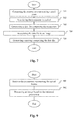
- Figure 7 is a flow chart for explaining a process for encoding an image captured by the optical acquisition system according to an embodiment of the disclosure.
- the processor 601 of the apparatus 600 executes the program capable of computing parameters representing a volume occupied by a set of rays of light in an object space of an optical system and encoding these parameters with an image captured by the optical acquisition system.
- the processor 601 computes, during a step 701, at least, the parameter representing the pixel beams 10, 20, 30, 40, 50 based on the parameters stored in the storage unit 602.
- the computed parameters depend on the type of representation of pixel beams 10, 20, 30, 40, 50, the manufacturer has chosen, i.e. representing a pixel beam by means of the parametric equation of a hyperboloid or by means of a chief ray and a family of generating rays.
- the processor 601 associates to a pixel of the sensor of the optical acquisition system that can sense light through a pupil of said optical acquisition system the parameters computed during step 701.
- Step 702 is executed for each pixel for of the sensor capable of sensing light through a pupil of the optical acquisition system.
- the processor 601 generates data file comprising the computed parameters representing the pixel beams associated to the different pixels of the sensor of the optical acquisition system.
- the generated data file is stored for example on a CD-ROM or a flash drive supplied with the optical acquisition system or on a server belonging to the manufacturer of the optical acquisition system.
- the processor 601 associates the data file comprising the computed parameters representing the pixel beams associated to the different pixels of the sensor of the optical acquisition system to an image captured by the optical acquisition system.
- the data file is for example stored in a specific filed of a header of the captured images.
- the processor 601 During a step 705, the processor 601 generates a message to be sent to an apparatus capable of processing an image captured by the optical acquisition system.
- the message comprises the data file comprising the computed parameters representing the pixel beams associated to the different pixels of the sensor of the optical acquisition system to an image captured by the optical acquisition system.
- the message consists in an image captured by the optical acquisition system embedding the data file in a field of its header.
- This message is then transmitted through the interface unit 605 to an external apparatus during a step 706.
- the interface unit 605 transmits a signal to the external apparatus via cable or wireless communication carrying the message comprising the parameters.
- the external apparatus is capable of processing an image captured by the optical system 21 using the parameters received in the message transmitted by the apparatus 600.
- Figure 8 is a schematic block diagram illustrating an example of an apparatus for processing an image captured by an optical acquisition system according to an embodiment of the present disclosure.
- the apparatus 800 comprises a processor 801, a storage unit 802, an input device 803, a display device 804, and an interface unit 805 which are connected by a bus 806.
- a processor 801 a storage unit 802, an input device 803, a display device 804, and an interface unit 805 which are connected by a bus 806.
- constituent elements of the computer apparatus 800 may be connected by a connection other than a bus connection.
- the processor 801 controls operations of the apparatus 800.
- the storage unit 802 stores at least one program capable of processing an image acquired by the optical acquisition system to be executed by the processor 801, and various data, including parameters related to a position of the pixel 22 on the sensor 23 or parameters related to the optical system 21 of the optical acquisition system, parameters used by computations performed by the processor 801, intermediate data of computations performed by the processor 801, and so on.
- the processor 801 may be formed by any known and suitable hardware, or software, or a combination of hardware and software.
- the processor 801 may be formed by dedicated hardware such as a processing circuit, or by a programmable processing unit such as a CPU (Central Processing Unit) that executes a program stored in a memory thereof.
- CPU Central Processing Unit
- the storage unit 802 may be formed by any suitable storage or means capable of storing the program, data, or the like in a computer-readable manner. Examples of the storage unit 802 include non-transitory computer-readable storage media such as semiconductor memory devices, and magnetic, optical, or magneto-optical recording media loaded into a read and write unit.
- the program causes the processor 801 to perform a process for processing an image captured by the optical acquisition system based on the parameters of the pixel beams provided with the image to be processed according to an embodiment of the present disclosure as described hereinafter with reference to figure 9 .
- the input device 803 may be formed by a keyboard, a pointing device such as a mouse, or the like for use by the user to input commands, to make user's selections of parameters used for processing the image captured by the optical acquisition system.
- the output device 804 may be formed by a display device to display, for example, a Graphical User Interface (GUI), images generated according to an embodiment of the present disclosure.
- GUI Graphical User Interface
- the input device 803 and the output device 804 may be formed integrally by a touchscreen panel, for example.
- the interface unit 805 provides an interface between the apparatus 800 and an external apparatus.
- the interface unit 805 may be communicable with the external apparatus via cable or wireless communication.
- the external apparatus may be optical acquisition system or the apparatus 600.
- Figure 9 is a flow chart for explaining a process for processing an image captured by the optical acquisition system according to an embodiment of the disclosure.
- the processor 801 of the apparatus 800 executes the program capable of processing an image captured by the optical acquisition system based on the parameters representing a pixel beam associated with the image to be processed.
- the processor 801 retrieves the parameters representing the pixel beams that are to be used to process the captured image either from a CD-ROM or a flash drive supplied with the optical acquisition system or by downloading the data file comprising said parameters from a server belonging to the manufacturer of the optical acquisition system. In an embodiment of the invention, the processor 801 retrieves these parameters in the header of the image to be processed.
- a step 902 processes, during a step 901, the image captured by the optical acquisition system based on the parameters representing the pixel beams 10, 20, 30, 40, 50 retrieved during step 901.
- the processing of the captured image may consists in de-multiplexing, de-mosaicking, refocusing, or mixing said captured image with at least another image captured by a different optical acquisition system, or a combination of any of these actions.
Landscapes
- Engineering & Computer Science (AREA)
- Multimedia (AREA)
- Signal Processing (AREA)
- Studio Devices (AREA)
- Image Processing (AREA)
Abstract
There are several types of plenoptic devices and camera arrays available on the market, and all these light field acquisition devices have their proprietary file format.. However, there is no standard supporting the acquisition and transmission of multidimensional information. It is interesting to obtain information related to a correspondence between pixels of a sensor of said optical acquisition system and an object space of said optical acquisition system. Indeed, knowing which portion of the object space of an optical acquisition system a pixel belonging to the sensor of said optical acquisition system is sensing enables the improvement of signal processing operations. The notion of pixel beam, which represents a volume occupied by a set of rays of light in an object space of an optical system of a camera is thus introduce.
Description
- The present invention relates to generation of data representing a light field.
- The acquisition of four-dimensional or 4D light-field data, which can be viewed as a sampling of a 4D light field, i.e. the recording of light rays, is explained in the article "Understanding camera trade-offs through a Bayesian analysis of light field projections" by Anat Levin and al., published in the conference proceedings of ECCV 2008 is an hectic research subject.
- Compared to classical two-dimensional or 2D images obtained from a camera, 4D light-field data enable a user to have access to more post-processing features that enhance the rendering of images and the interactivity with the user. For example, with 4D light-field data, it is possible to perform refocusing of images with freely selected distances of focalization meaning that the position of a focal plane can be specified/selected a posteriori, as well as changing slightly the point of view in the scene of an image. In order to acquire 4D light-field data, several techniques can be used. For example, a plenoptic camera is able to acquire 4D light-field data. Details of the architecture of a plenoptic camera are provided in
Figure 1A. Figure 1A is a diagram schematically representing aplenoptic camera 100. Theplenoptic camera 100 comprises amain lens 101, amicrolens array 102 comprising a plurality of micro-lenses 103 arranged in a two-dimensional array and animage sensor 104. - Another way to acquire 4D light-field data is to use a camera array as depicted in
Figure 1B. Figure 1B represents amulti-array camera 110. Themulti-array camera 110 comprises alens array 112 and animage sensor 114. - In the example of the
plenoptic camera 100 as shown infigure 1A , themain lens 101 receives light from an object (not shown on the figure) in an object field of themain lens 101 and passes the light through an image field of themain lens 101. - At last, another way of acquiring a 4D light field is to use a conventional camera that is configured to capture a sequence of 2D images of a same scene at different focal planes. For example, the technique described in the document "Light ray field capture using focal plane sweeping and its optical reconstruction using 3D displays" by J.-H. Park et al., published in OPTICS EXPRESS, Vol. 22, No. 21 , in October 2014, may be used to achieve the acquisition of 4D light field data by means of a conventional camera.
- There are several ways to represent 4D light-field data. Indeed, in the Chapter 3.3 of the Ph.D dissertation thesis entitled "Digital Light Field Photograbhy" by Ren Ng, published in July 2006, three different ways to represent 4D light-field data are described. Firstly, 4D light-field data can be represented, when recorded by a plenoptic camera by a collection of micro-lens images. 4D light-field data in this representation are named raw images or raw 4D light-field data. Secondly, 4D light-field data can be represented, either when recorded by a plenoptic camera or by a camera array, by a set of sub-aperture images. A sub-aperture image corresponds to a captured image of a scene from a point of view, the point of view being slightly different between two sub-aperture images. These sub-aperture images give information about the parallax and depth of the imaged scene. Thirdly, 4D light-field data can be represented by a set of epipolar images see for example the article entitled : "Generating EPI Representation of a 4D Light Fields with a Single Lens Focused Plenoptic Camera", by S. Wanner and al., published in the conference proceedings of ISVC 2011.
- There are several types of plenoptic devices and camera arrays available on the market, and all these light field acquisition devices have their proprietary file format. Thus it appears that light-field technology cannot live besides regular 2D or 3D imaging as there is no standard supporting the acquisition and transmission of multi-dimensional information. The present invention has been devised with the foregoing in mind.
- According to a first aspect of the invention there is provided an apparatus for encoding an image captured by an optical acquisition system, said apparatus comprising a processor configured to associate, to at least one pixel of a sensor of said optical acquisition system, parameters representing a sampling of an object space of the optical acquisition system, said parameters defining a volume in the object space of the optical acquisition system occupied by a set of rays of light that the at least one pixel of the sensor of said optical acquisition system can sense through a pupil of said optical acquisition system, said volume occupied by said set of rays of light being called a pixel beam.
- According to an embodiment of the invention, the processor is configured to compute the parameters representing a pixel beam to be associated to at least one pixel of the sensor of the optical acquisition system.
- According to an embodiment of the invention, the processor is configured to associate the parameters representing pixel beams to an image acquired by the optical acquisition system to be encoded.
- According to an embodiment of the invention, the parametric representation of the pixel beam is a hyperboloid of one sheet defined by the following equations :

where x, y, and z are the coordinates in the object space of a point belonging to the surface of the hyperboloid, zP, θx, θy, a, zP representing a distance of the smallest section of the pixel beam, called the waist, which corresponds to the conjugate of the pixel in the object space of the optical acquisition system in a direction normal to a surface of the pupil, θx, θy representing shear angles defining a direction of the waist from the centre of the pupil, a representing a dimension of waist; c is a parameter dependent on a defining the angular aperture of the pixel beam, and v is an angle varying in [0, 2π] interval. - According to an embodiment of the invention, the parametric representation of the pixel beam is an hyperboloid of one sheet defined by the following equations :

where AO is the parameter representing an aspect ratio for an asymmetric pupil, AP is the parameter representing an aspect ratio for an asymmetric waist, a is the parameter related to a propagation of a section of the pixel beam between the pupil and the waist, ρO is the parameter representing a polar radius factor for the pupil and ρP is the parameter representing a polar radius factor for the waist. - According to an embodiment of the invention, a pixel beam is represented by at least a first set of parameters representing an axis of the hyperboloid called a chief ray and a second set of parameters representing a family of generating rays enabling the generation of a surface of the hyperboloid by rotating around the chief ray.
- Another aspect of the invention concerns a method for encoding an image captured by an optical acquisition system, said method comprising associating, to at least one pixel of a sensor of said optical acquisition system, parameters representing a sampling of an object space of the optical acquisition system, said parameters defining a volume in the object space of the optical acquisition system occupied by a set of rays of light that the at least one pixel of the sensor of said optical acquisition system can sense through a pupil of said optical acquisition system, said volume occupied by said set of rays of light being called a pixel beam.
- According to an embodiment of the invention, the method further comprises computing the parameters representing a pixel beam to be associated to at least one pixel of the sensor of the optical acquisition system.
- According to an embodiment of the invention, the method further comprises associating the parameters representing pixel beams to an image acquired by the optical acquisition system to be encoded.
- Another object of the invention concerns an apparatus for processing an image captured by an optical acquisition system, said apparatus comprising a processor configured to process said image based on parameters associated to at least one pixel of a sensor of the optical acquisition system, said parameters defining a volume in an object space of the optical acquisition system occupied by a set of rays of light that the at least on pixel of the sensor of said optical acquisition system can sense through a pupil of said optical acquisition system, said volume occupied by said set of rays of light being called a pixel beam.
- According to an embodiment of the invention, the processor is configured to process the captured image by :
- de-multiplexing said captured image,
- de-mosaicking said captured image,
- refocusing said captured image, or
- mixing said captured image with at least another image captured by a different optical acquisition system.
- Another aspect of the invention concerns a method for processing an image captured by an optical acquisition system, said method comprising processing said image based on parameters associated to at least one pixel of a sensor of the optical acquisition system, said parameters defining a volume in an object space of the optical acquisition system occupied by a set of rays of light that the at least on pixel of the sensor of said optical acquisition system can sense through a pupil of said optical acquisition system, said volume occupied by said set of rays of light being called a pixel beam.
- According to an embodiment of the invention, processing the captured image consists in :
- de-multiplexing said captured image,
- de-mosaicking said captured image,
- refocusing said captured image, or
- mixing said captured image with at least another image captured by a different optical acquisition system.
- Finally, another object of the invention is a signal transmitted by a first apparatus capable of encoding an image captured by an optical acquisition system, to a second apparatus capable of processing said captured image captured, said signal carrying a message comprising parameters representing a sampling of an object space of the optical acquisition system, said parameters defining a volume in the object space of the optical acquisition system occupied by a set of rays of light that at least one pixel of a sensor of said optical acquisition system can sense through a pupil of said optical acquisition system, the processing the captured image by the second apparatus being based on said parameters.
- Some processes implemented by elements of the invention may be computer implemented. Accordingly, such elements may take the form of an entirely hardware embodiment, an entirely software embodiment (including firmware, resident software, micro-code, etc.) or an embodiment combining software and hardware aspects that may all generally be referred to herein as a "circuit", "module" or "system'. Furthermore, such elements may take the form of a computer program product embodied in any tangible medium of expression having computer usable program code embodied in the medium.
- Since elements of the present invention can be implemented in software, the present invention can be embodied as computer readable code for provision to a programmable apparatus on any suitable carrier medium. A tangible carrier medium may comprise a storage medium such as a floppy disk, a CD-ROM, a hard disk drive, a magnetic tape device or a solid state memory device and the like. A transient carrier medium may include a signal such as an electrical signal, an electronic signal, an optical signal, an acoustic signal, a magnetic signal or an electromagnetic signal, e.g. a microwave or RF signal.
- Embodiments of the invention will now be described, by way of example only, and with reference to the following drawings in which:
-
Figure 1A is a diagram schematically representing a plenoptic camera; -
Figure 1B represents a multi-array camera, -
Figure 2 represents a volume occupied by a set of rays of light in an object space of an optical system of a camera or optical acquisition system, -
Figure 3 represents a hyperboloid of one sheet, -
Figure 4 represents another view of a hyperboloid of one sheet, -
Figure 5 represents a chief ray and a generating ray defining a pixel beam according to an embodiment of the invention, -
Figure 6 is a schematic block diagram illustrating an example of an apparatus for encoding an image captured by an optical acquisition system according to an embodiment of the present disclosure, -
Figure 7 is a flow chart for explaining a process for encoding an image captured by the optical acquisition system according to an embodiment of the disclosure, -
Figure 8 is a schematic block diagram illustrating an example of an apparatus for processing an image captured by an optical acquisition system according to an embodiment of the present disclosure, -
Figure 9 is a flow chart for explaining a process for processing an image captured by the optical acquisition system according to an embodiment of the disclosure. - As will be appreciated by one skilled in the art, aspects of the present principles can be embodied as a system, method or computer readable medium. Accordingly, aspects of the present principles can take the form of an entirely hardware embodiment, an entirely software embodiment, (including firmware, resident software, micro-code, and so forth) or an embodiment combining software and hardware aspects that can all generally be referred to herein as a "circuit", "module", or "system". Furthermore, aspects of the present principles can take the form of a computer readable storage medium. Any combination of one or more computer readable storage medium(a) may be utilized.
- For any optical acquisition system, may it be plenoptic or not, in addition to raw images or epipolar images representing 4D light-field data captured by the optical acquisition system, it is interesting to obtain information related to a correspondence between pixels of a sensor of said optical acquisition system and an object space of said optical acquisition system. Knowing which portion of the object space of an optical acquisition system a pixel belonging to the sensor of said optical acquisition system is sensing enables the improvement of signal processing operations such as de-multiplexing, de-mosaicking, refocusing, etc., and the mixing of images captured by different optical systems with different characteristics. Furthermore, information related to the correspondence between the pixels of the sensor of the optical acquisition system and the object space of said optical acquisition system are independent of the optical acquisition system.
- The present disclosure introduces the notion of
pixel beam 10, shown onfigure 2 , which represents a volume occupied by a set of rays of light in an object space of an optical system 11 of a camera or optical acquisition system (not shown onfigure 2 ). The set of rays of light is sensed by apixel 22 of asensor 23 of the camera through apupil 24 of saidoptical system 21. Theoptical system 21 may be a combination of lenses fit for photo or video cameras. A pupil of an optical system is defined as the image of an aperture stop as seen through said optical system, i.e. the lenses of the optical acquisition system, which precedes said aperture stop. An aperture stop is an opening which limits the amount of light which passes through the optical system of the optical acquisition system. For example, an adjustable blade diaphragm located inside a camera lens is the aperture stop for the lens. The amount of light admitted through the diaphragm is controlled by the diameter of the diaphragm opening which may adapted depending of the amount of light a user of the camera wishes to admit. For example, making the aperture smaller reduces the amount of light admitted through the diaphragm, and, simultaneously, increases the depth of focus. The apparent size of a stop may be larger or smaller than its physical size because of the refractive action of a portion of the lens. Formally, a pupil is the image of the aperture stop through all lenses of the optical acquisition system located between the physical stop and the observation space. - A
pixel beam 10 is defined as a pencil of rays of light that reach a givenpixel 22 when propagating through theoptical system 21 via anentrance pupil 24. As light travels on straight lines in free space, the shape of such a pixel beam 20 can be defined by two sections, one being theconjugate 25 of thepixel 22, and the other being theentrance pupil 24. Thepixel 22 is defined by its non-null surface and its sensitivity map. - Thus, a
pixel beam 30 may be represented by an hyperboloid of one sheet, as shown onfigure 3 , supported by two elements : thepupil 34 and theconjugate 35 of thepixel 22 in the object space. - A hyperboloid of one sheet is a ruled surface that can support the notion of pencil of rays of light and is compatible with the notion of "étendue" of physical light beams, notion linked to the preservation of energy across sections of the physical light beams.
- As represented on
figure 4 , a hyperboloid of onesheet 40 is mostly identical to itsasymptotic cones waist 45, which corresponds to the conjugate 25 in the object space. For plenoptic systems, such as light-field cameras, this is the region where space sampling by multiple path rays is performed. Sampling space with cones in this region is not adequate, aspixel 22 sensitivity is significant on some tens of square microns on its surface and cannot be represented by a mathematical point with infinitely small surface as would be a cone tip. - In a first embodiment of the invention, each
pixel beam pixel conjugate pupil pupil same pupil optical system 21 sensed by thepixel 22 through thepupil 24, i.e. to a givencouple pixel 22/pupil unique pixel beam same pupil - An origin O of a coordinate system (x, y, z) in which the parameters of the
pixel beam pupil 24 as shown onfigure 2 , where the z axis defines a direction normal to the surface of thepupil - The parameters θ x , θ y , define chief ray directions relative to the entrance of the
pupil 24 centre. They depend on thepixel 22 position on thesensor 23 and on the optical elements of theoptical system 21. More precisely, the parameters θ x , θ y represent shear angles defining a direction of theconjugate 25 of thepixel 22 from the centre of thepupil 24. - The parameter zP represents a distance of the
waist 45 of thepixel beam conjugate 25 of thepixel 22, along the z axis. - The parameter a represents the radius of the
waist 45 of thepixel beam - For
optical systems 21 where optical distortions and field curvatures may be modelled, the parameters zP and a can depend on the parameters θ x and θ y via parametric functions. - The four independent parameters are related to the
pixel 22 and itsconjugate 25. - The six complementary pupilar parameters defining a
pixel beam - r which represents the
pupil - xO , yO , zO which represent the coordinates of the
pupil - θ x0, θ y0 which represent the orientation of the
pupil - These six pupilar parameters are related to the
pupil pixel 22 and itsconjugate 25 and on the parameters r related to thepupil pixel beam 
- Thus the expression of the parameter c is given by the following equation :

- The coordinates (x, y, z), in the object space, of points belonging to the surface delimiting the
pixel beam pupil 24, and to theconjugate 25 of the pixel. Thus, equation (2) enabling the generation of the hyperboloid of one sheet representing thepixel beam 
- A parametric equation (3) of the same hyperboloid representing the
pixel beam 
wherein v is an angle in the (x, y) plane enabling the generation of thepixel beam pupil pixel 22 and its conjugate 25 are circular and that the section of thepupil - In order to obtain a precise description of how the pixel beams 20, 30, 40 sample the object space of the
optical system 21, it is interesting to determine how the geometry of the section of thepixel 22 and the section of thepupil different pixels 22 of thesensor 23. - Another set of parameters is thus defined in order to describe the shape of the sections of the
pupil pixel 22 and of theconjugate 25 of thepixel 22. - A first independent parameter AO is defined. The parameter AO represents an aspect ratio to allow for
asymmetric pupil - A second independent parameter AP is defined. The parameter AP represents an aspect ratio to allow for asymmetric pixel beams at the conjugate 25, 45 of the pixel 22 - the waist.
- A third parameter dependent parameter α is defined a s follow :

α is a coefficient which represents the propagation of thepixel beam pupil pixel 22, independently from the shape of the sections of thepupil pixel 22; and from the conjugate 25, 45 of thepixel 22 to infinity. The parameter k is a parameter adjusting the evolution of thepixel beam pupil pixel 22. - Two parameters ρ O and ρ P , called polar radius factors, are describing respectively the shape of the
pupil pixel 22. The parameters ρ O and ρ P are defined by the following equation :
- The following table, called table 1, gives examples of the values of parameters ρ O and ρ P when AO = AP = 1.0 :
Table 1 ρ 0 ρ P 1.0 1.0 circular pupil pixel conjugate 1.0 ρ circular pupil shape pixel conjugate ρ 1.0 square shape pupil circular pixel conjugate ρ ρ square shape pupil shape pixel conjugate - Taking into account the above defined parameters related to the shape of the sections of the
pupil pixel 22 and theconjugate 25 of thepixel 22, an extended parametric equation (6) of the hyperboloid representing thepixel beam 
- In another embodiment of the invention, since a hyperboloid of one sheet is a ruled surface it may be described by two families of straight lines, the first family being called generating rays rotating around an axis called a chief ray and consisting in the second family. The chief ray and any generating rays are sufficient to define a pixel beam.
- As represented on
figure 5 , the first ray to be considered as describing a pixel beam 50 is its axis orchief ray 51. Thechief ray 51 corresponds to the z axis of thehyperboloid figure 2 . - Shearing the
hyperboloid 
- The second ray to consider when describing the
pixel beam ray 52. The family of generatingrays 52 describes the surface of the hyperboloid 50. - Information related to a correspondence between pixels of a sensor of said optical acquisition system and an object space of said optical acquisition system may take the form of either a set of parameters comprising the four independent parameters: zP , θ x , θ y , a defining the position and size of the
pixel conjugate pupil pupil chief ray 51 and a family of generatingrays 52 when the pixel beam is 20, 30, 40, 50 to be represented by these tworays - Those additional information related to pixel beams are metadata associated to a given optical acquisition system. They may be provided as a data file stored for example on a CD-ROM or a flash drive supplied with the optical acquisition system. The data file containing the additional information related to pixel beams may also be downloaded from a server belonging to the manufacturer of the optical acquisition system. In an embodiment of the invention, these additional information related to pixel beams may also be embedded in an header of the images captured by the optical acquisition system.
- The knowledge of these information related to pixel beams enables the processing of images captured by any optical acquisition system independently of the proprietary file format and of the features of the optical acquisition system used to capture the images to be processed.
-
Figure 6 is a schematic block diagram illustrating an example of an apparatus for encoding an image captured by an optical acquisition system according to an embodiment of the present disclosure. - The
apparatus 600 comprises aprocessor 601, astorage unit 602, aninput device 603, adisplay device 604, and aninterface unit 605 which are connected by abus 606. Of course, constituent elements of thecomputer apparatus 600 may be connected by a connection other than a bus connection. - The
processor 601 controls operations of theapparatus 600. Thestorage unit 602 stores at least one program capable of encoding an image acquired by the optical acquisition system to be executed by theprocessor 601, and various data, including parameters related to a position of thepixel 22 on thesensor 23 or parameters related to theoptical system 21 of the optical acquisition system, parameters used by computations performed by theprocessor 601, intermediate data of computations performed by theprocessor 601, and so on. Theprocessor 601 may be formed by any known and suitable hardware, or software, or a combination of hardware and software. For example, theprocessor 601 may be formed by dedicated hardware such as a processing circuit, or by a programmable processing unit such as a CPU (Central Processing Unit) that executes a program stored in a memory thereof. - The
storage unit 602 may be formed by any suitable storage or means capable of storing the program, data, or the like in a computer-readable manner. Examples of thestorage unit 602 include non-transitory computer-readable storage media such as semiconductor memory devices, and magnetic, optical, or magneto-optical recording media loaded into a read and write unit. The program causes theprocessor 601 to perform a process for computing parameters representing a volume occupied by a set of rays of light in an object space of an optical system and encoding these parameters with an image captured by the optical acquisition system according to an embodiment of the present disclosure as described hereinafter with reference tofigure 7 . - The
input device 603 may be formed by a keyboard, a pointing device such as a mouse, or the like for use by the user to input commands, to make user's selections of parameters used for generating a parametric representation of a volume occupied by a set of rays of light in an object space of an optical system. Theoutput device 604 may be formed by a display device to display, for example, a Graphical User Interface (GUI), images generated according to an embodiment of the present disclosure. Theinput device 603 and theoutput device 604 may be formed integrally by a touchscreen panel, for example. - The
interface unit 605 provides an interface between theapparatus 600 and an external apparatus. Theinterface unit 605 may be communicable with the external apparatus via cable or wireless communication. In an embodiment, the external apparatus may be optical acquisition system. -
Figure 7 is a flow chart for explaining a process for encoding an image captured by the optical acquisition system according to an embodiment of the disclosure. - The
processor 601 of theapparatus 600 executes the program capable of computing parameters representing a volume occupied by a set of rays of light in an object space of an optical system and encoding these parameters with an image captured by the optical acquisition system. - Thus, the
processor 601 computes, during astep 701, at least, the parameter representing the pixel beams 10, 20, 30, 40, 50 based on the parameters stored in thestorage unit 602. The computed parameters depend on the type of representation of pixel beams 10, 20, 30, 40, 50, the manufacturer has chosen, i.e. representing a pixel beam by means of the parametric equation of a hyperboloid or by means of a chief ray and a family of generating rays. - During a
step 702, theprocessor 601 associates to a pixel of the sensor of the optical acquisition system that can sense light through a pupil of said optical acquisition system the parameters computed duringstep 701. Step 702 is executed for each pixel for of the sensor capable of sensing light through a pupil of the optical acquisition system. - During a
step 703, theprocessor 601 generates data file comprising the computed parameters representing the pixel beams associated to the different pixels of the sensor of the optical acquisition system. The generated data file is stored for example on a CD-ROM or a flash drive supplied with the optical acquisition system or on a server belonging to the manufacturer of the optical acquisition system. - In another embodiment of the invention, during a
step 704, theprocessor 601 associates the data file comprising the computed parameters representing the pixel beams associated to the different pixels of the sensor of the optical acquisition system to an image captured by the optical acquisition system. The data file is for example stored in a specific filed of a header of the captured images. - During a
step 705, theprocessor 601 generates a message to be sent to an apparatus capable of processing an image captured by the optical acquisition system. In a first embodiment of the invention, the message comprises the data file comprising the computed parameters representing the pixel beams associated to the different pixels of the sensor of the optical acquisition system to an image captured by the optical acquisition system. In a second embodiment of the invention, the message consists in an image captured by the optical acquisition system embedding the data file in a field of its header. - This message is then transmitted through the
interface unit 605 to an external apparatus during a step 706. Theinterface unit 605 transmits a signal to the external apparatus via cable or wireless communication carrying the message comprising the parameters. The external apparatus is capable of processing an image captured by theoptical system 21 using the parameters received in the message transmitted by theapparatus 600. -
Figure 8 is a schematic block diagram illustrating an example of an apparatus for processing an image captured by an optical acquisition system according to an embodiment of the present disclosure. - The
apparatus 800 comprises aprocessor 801, astorage unit 802, aninput device 803, adisplay device 804, and aninterface unit 805 which are connected by abus 806. Of course, constituent elements of thecomputer apparatus 800 may be connected by a connection other than a bus connection. - The
processor 801 controls operations of theapparatus 800. Thestorage unit 802 stores at least one program capable of processing an image acquired by the optical acquisition system to be executed by theprocessor 801, and various data, including parameters related to a position of thepixel 22 on thesensor 23 or parameters related to theoptical system 21 of the optical acquisition system, parameters used by computations performed by theprocessor 801, intermediate data of computations performed by theprocessor 801, and so on. Theprocessor 801 may be formed by any known and suitable hardware, or software, or a combination of hardware and software. For example, theprocessor 801 may be formed by dedicated hardware such as a processing circuit, or by a programmable processing unit such as a CPU (Central Processing Unit) that executes a program stored in a memory thereof. - The
storage unit 802 may be formed by any suitable storage or means capable of storing the program, data, or the like in a computer-readable manner. Examples of thestorage unit 802 include non-transitory computer-readable storage media such as semiconductor memory devices, and magnetic, optical, or magneto-optical recording media loaded into a read and write unit. The program causes theprocessor 801 to perform a process for processing an image captured by the optical acquisition system based on the parameters of the pixel beams provided with the image to be processed according to an embodiment of the present disclosure as described hereinafter with reference tofigure 9 . - The
input device 803 may be formed by a keyboard, a pointing device such as a mouse, or the like for use by the user to input commands, to make user's selections of parameters used for processing the image captured by the optical acquisition system. Theoutput device 804 may be formed by a display device to display, for example, a Graphical User Interface (GUI), images generated according to an embodiment of the present disclosure. Theinput device 803 and theoutput device 804 may be formed integrally by a touchscreen panel, for example. - The
interface unit 805 provides an interface between theapparatus 800 and an external apparatus. Theinterface unit 805 may be communicable with the external apparatus via cable or wireless communication. In an embodiment, the external apparatus may be optical acquisition system or theapparatus 600. -
Figure 9 is a flow chart for explaining a process for processing an image captured by the optical acquisition system according to an embodiment of the disclosure. - The
processor 801 of theapparatus 800 executes the program capable of processing an image captured by the optical acquisition system based on the parameters representing a pixel beam associated with the image to be processed. - Thus, the
processor 801, during astep 901, retrieves the parameters representing the pixel beams that are to be used to process the captured image either from a CD-ROM or a flash drive supplied with the optical acquisition system or by downloading the data file comprising said parameters from a server belonging to the manufacturer of the optical acquisition system. In an embodiment of the invention, theprocessor 801 retrieves these parameters in the header of the image to be processed. - Then, during a
step 902, processes, during astep 901, the image captured by the optical acquisition system based on the parameters representing the pixel beams 10, 20, 30, 40, 50 retrieved duringstep 901. - The processing of the captured image may consists in de-multiplexing, de-mosaicking, refocusing, or mixing said captured image with at least another image captured by a different optical acquisition system, or a combination of any of these actions. Although the present invention has been described hereinabove with the reference to specific embodiments, the present invention is not limited to the specific embodiments, and modifications will be apparent to a skilled person in the art which lie within the scope of the present invention.
- Many further modifications and variations will suggest themselves to those versed in the art upon making reference to the foregoing illustrative embodiments, which are given by way of example only and which are not intended to limit the scope of the invention, that being determined solely by the appended claims. In particular the different features from different embodiments may be interchanged, where appropriate.
Claims (15)
- An apparatus for encoding an image captured by an optical acquisition system, said apparatus comprising a processor configured to associate, to at least one pixel of a sensor of said optical acquisition system, parameters representing a sampling of an object space of the optical acquisition system, said parameters defining a volume in the object space of the optical acquisition system occupied by a set of rays of light that the at least one pixel of the sensor of said optical acquisition system can sense through a pupil of said optical acquisition system, said volume occupied by said set of rays of light being called a pixel beam.
- The apparatus according to claim 1 wherein the processor is configured to compute the parameters representing a pixel beam to be associated to at least one pixel of the sensor of the optical acquisition system.
- The apparatus according to claim 2 wherein the processor is configured to associate the parameters representing pixel beams to an image acquired by the optical acquisition system to be encoded.
- The apparatus according any of the preceding claims wherein the parametric representation of the pixel beam is a hyperboloid of one sheet defined by the following equations :

where x, y, and z are the coordinates in the object space of a point belonging to the surface of the hyperboloid, zP, θx, θy, a, zP representing a distance of the smallest section of the pixel beam, called the waist, which corresponds to the conjugate of the pixel in the object space of the optical acquisition system in a direction normal to a surface of the pupil, θx, θy representing shear angles defining a direction of the waist from the centre of the pupil, a representing a dimension of waist; c is a parameter dependent on a defining the angular aperture of the pixel beam, and v is an angle varying in [0, 2π] interval. - The apparatus according to claim 4 wherein the parametric representation of the pixel beam is an hyperboloid of one sheet defined by the following equations :

where AO is the parameter representing an aspect ratio for an asymmetric pupil, AP is the parameter representing an aspect ratio for an asymmetric waist, a is the parameter related to a propagation of a section of the pixel beam between the pupil and the waist, ρO is the parameter representing a polar radius factor for the pupil and ρP is the parameter representing a polar radius factor for the waist. - The apparatus according to any of the claims 1 to 3 wherein a pixel beam is represented by at least a first set of parameters representing an axis of the hyperboloid called a chief ray and a second set of parameters representing a family of generating rays enabling the generation of a surface of the hyperboloid by rotating around the chief ray.
- A method for encoding an image captured by an optical acquisition system, said method comprising associating, to at least one pixel of a sensor of said optical acquisition system, parameters representing a sampling of an object space of the optical acquisition system, said parameters defining a volume in the object space of the optical acquisition system occupied by a set of rays of light that the at least one pixel of the sensor of said optical acquisition system can sense through a pupil of said optical acquisition system, said volume occupied by said set of rays of light being called a pixel beam.
- The method according to claim 7 further comprising computing the parameters representing a pixel beam to be associated to at least one pixel of the sensor of the optical acquisition system.
- The method according to claim 8 further comprising associating the parameters representing pixel beams to an image acquired by the optical acquisition system to be encoded.
- An apparatus for processing an image captured by an optical acquisition system, said apparatus comprising a processor configured to process said image based on parameters associated to at least one pixel of a sensor of the optical acquisition system, said parameters defining a volume in an object space of the optical acquisition system occupied by a set of rays of light that the at least on pixel of the sensor of said optical acquisition system can sense through a pupil of said optical acquisition system, said volume occupied by said set of rays of light being called a pixel beam.
- The apparatus according to claim 10 wherein the processor is configured to process the captured image by :- de-multiplexing said captured image,- de-mosaicking said captured image,- refocusing said captured image, or- mixing said captured image with at least another image captured by a different optical acquisition system.
- A method for processing an image captured by an optical acquisition system, said method comprising processing said image based on parameters associated to at least one pixel of a sensor of the optical acquisition system, said parameters defining a volume in an object space of the optical acquisition system occupied by a set of rays of light that the at least on pixel of the sensor of said optical acquisition system can sense through a pupil of said optical acquisition system, said volume occupied by said set of rays of light being called a pixel beam.
- The method according to claim 12 wherein processing the captured image consists in :- de-multiplexing said captured image,- de-mosaicking said captured image,- refocusing said captured image, or- mixing said captured image with at least another image captured by a different optical acquisition system.
- A signal transmitted by a first apparatus capable of encoding an image captured by an optical acquisition system, to a second apparatus capable of processing said captured image captured, said signal carrying a message comprising parameters representing a sampling of an object space of the optical acquisition system, said parameters defining a volume in the object space of the optical acquisition system occupied by a set of rays of light that at least one pixel of a sensor of said optical acquisition system can sense through a pupil of said optical acquisition system, the processing the captured image by the second apparatus being based on said parameters.
- A computer program characterized in that it comprises program code instructions for the implementation of the method for encoding an image captured by an optical acquisition system m according to any of claims 7 to 9 when the program is executed by a processor.
Priority Applications (13)
| Application Number | Priority Date | Filing Date | Title |
|---|---|---|---|
| EP15306444.9A EP3145195A1 (en) | 2015-09-17 | 2015-09-17 | An apparatus and a method for encoding an image captured by an optical acquisition system |
| EP16754510.2A EP3350998A1 (en) | 2015-09-17 | 2016-08-23 | An apparatus and a method for encoding an image captured by an optical acquisition system |
| KR1020187010403A KR102918966B1 (en) | 2015-09-17 | 2016-08-23 | Device and method for encoding an image captured by an optical acquisition system |
| US15/759,874 US10872442B2 (en) | 2015-09-17 | 2016-08-23 | Apparatus and a method for encoding an image captured by an optical acquisition system |
| RU2018113714A RU2729698C2 (en) | 2015-09-17 | 2016-08-23 | Apparatus and method for encoding an image captured by an optical system for acquiring data |
| CA2998661A CA2998661A1 (en) | 2015-09-17 | 2016-08-23 | An apparatus and a method for encoding an image captured by an optical acquisition system |
| CN201680064918.XA CN108353187B (en) | 2015-09-17 | 2016-08-23 | Apparatus and method for encoding an image captured by an optical acquisition system |
| BR112018005339-2A BR112018005339A2 (en) | 2015-09-17 | 2016-08-23 | apparatus and method for encoding an image captured by an optical acquisition system |
| AU2016321728A AU2016321728B2 (en) | 2015-09-17 | 2016-08-23 | An apparatus and a method for encoding an image captured by an optical acquisition system |
| PCT/EP2016/069884 WO2017045875A1 (en) | 2015-09-17 | 2016-08-23 | An apparatus and a method for encoding an image captured by an optical acquisition system |
| MX2018003266A MX2018003266A (en) | 2015-09-17 | 2016-08-23 | An apparatus and a method for encoding an image captured by an optical acquisition system. |
| JP2018514433A JP6847097B2 (en) | 2015-09-17 | 2016-08-23 | Equipment and methods for coding images captured by optical acquisition systems |
| TW105128314A TW201723635A (en) | 2015-09-17 | 2016-09-02 | Device and method for capturing image code captured by optical acquisition system |
Applications Claiming Priority (1)
| Application Number | Priority Date | Filing Date | Title |
|---|---|---|---|
| EP15306444.9A EP3145195A1 (en) | 2015-09-17 | 2015-09-17 | An apparatus and a method for encoding an image captured by an optical acquisition system |
Publications (1)
| Publication Number | Publication Date |
|---|---|
| EP3145195A1 true EP3145195A1 (en) | 2017-03-22 |
Family
ID=54252222
Family Applications (1)
| Application Number | Title | Priority Date | Filing Date |
|---|---|---|---|
| EP15306444.9A Withdrawn EP3145195A1 (en) | 2015-09-17 | 2015-09-17 | An apparatus and a method for encoding an image captured by an optical acquisition system |
Country Status (1)
| Country | Link |
|---|---|
| EP (1) | EP3145195A1 (en) |
Citations (3)
| Publication number | Priority date | Publication date | Assignee | Title |
|---|---|---|---|---|
| EP2419884A1 (en) * | 2009-04-18 | 2012-02-22 | Refocus Imaging, Inc. | Light field camera image, file and configuration data, and methods of using, storing and communicating same |
| US20130235261A1 (en) * | 2012-03-07 | 2013-09-12 | Ricoh Co., Ltd. | Plenoptic Imaging System with a Body and Detachable Plenoptic Imaging Components |
| US20140098191A1 (en) * | 2012-10-05 | 2014-04-10 | Vidinoti Sa | Annotation method and apparatus |
-
2015
- 2015-09-17 EP EP15306444.9A patent/EP3145195A1/en not_active Withdrawn
Patent Citations (3)
| Publication number | Priority date | Publication date | Assignee | Title |
|---|---|---|---|---|
| EP2419884A1 (en) * | 2009-04-18 | 2012-02-22 | Refocus Imaging, Inc. | Light field camera image, file and configuration data, and methods of using, storing and communicating same |
| US20130235261A1 (en) * | 2012-03-07 | 2013-09-12 | Ricoh Co., Ltd. | Plenoptic Imaging System with a Body and Detachable Plenoptic Imaging Components |
| US20140098191A1 (en) * | 2012-10-05 | 2014-04-10 | Vidinoti Sa | Annotation method and apparatus |
Non-Patent Citations (3)
| Title |
|---|
| ANAT LEVIN: "Understanding camera trade-o .r through a Ballesian analvsis of light field projections", THE CONFERENCE PROCEEDINGS OF ECCV, 2008 |
| J.-H. PARK ET AL.: "Light ray-field capture using focal plane sweeping and its optical reconstruction using 3D displays", OPTICS EXPRESS, vol. 22, no. 21, October 2014 (2014-10-01) |
| S. WANNER: "Generating EPI Representation of a 4D Light Fields with a Single Lens Focused Plenoptic Camera", THE CONFERENCE PROCEEDINGS OF ISVC, 2011 |
Similar Documents
| Publication | Publication Date | Title |
|---|---|---|
| EP3144880B1 (en) | A method and an apparatus for generating data representative of a light field | |
| US10613338B2 (en) | Apparatus and a method for calibrating an optical aquisition system | |
| EP3398161B1 (en) | A method and an apparatus for generating data representative of a pixel beam | |
| JP2018531448A6 (en) | Apparatus and method for calibrating an optical capture system | |
| EP3188124A1 (en) | A method and an apparatus for generating data representative of a pixel beam | |
| US10872442B2 (en) | Apparatus and a method for encoding an image captured by an optical acquisition system | |
| EP3350982B1 (en) | An apparatus and a method for generating data representing a pixel beam | |
| US11092820B2 (en) | Apparatus and a method for generating data representative of a pixel beam |
Legal Events
| Date | Code | Title | Description |
|---|---|---|---|
| PUAI | Public reference made under article 153(3) epc to a published international application that has entered the european phase |
Free format text: ORIGINAL CODE: 0009012 |
|
| AK | Designated contracting states |
Kind code of ref document: A1 Designated state(s): AL AT BE BG CH CY CZ DE DK EE ES FI FR GB GR HR HU IE IS IT LI LT LU LV MC MK MT NL NO PL PT RO RS SE SI SK SM TR |
|
| AX | Request for extension of the european patent |
Extension state: BA ME |
|
| STAA | Information on the status of an ep patent application or granted ep patent |
Free format text: STATUS: THE APPLICATION IS DEEMED TO BE WITHDRAWN |
|
| 18D | Application deemed to be withdrawn |
Effective date: 20170923 |