EP3145075A1 - Three-phase variable reference pulse width modulation - Google Patents
Three-phase variable reference pulse width modulation Download PDFInfo
- Publication number
- EP3145075A1 EP3145075A1 EP16188688.2A EP16188688A EP3145075A1 EP 3145075 A1 EP3145075 A1 EP 3145075A1 EP 16188688 A EP16188688 A EP 16188688A EP 3145075 A1 EP3145075 A1 EP 3145075A1
- Authority
- EP
- European Patent Office
- Prior art keywords
- cycle
- voltage
- motor
- pulse width
- controller
- Prior art date
- Legal status (The legal status is an assumption and is not a legal conclusion. Google has not performed a legal analysis and makes no representation as to the accuracy of the status listed.)
- Granted
Links
Images



Classifications
-
- H—ELECTRICITY
- H02—GENERATION; CONVERSION OR DISTRIBUTION OF ELECTRIC POWER
- H02P—CONTROL OR REGULATION OF ELECTRIC MOTORS, ELECTRIC GENERATORS OR DYNAMO-ELECTRIC CONVERTERS; CONTROLLING TRANSFORMERS, REACTORS OR CHOKE COILS
- H02P23/00—Arrangements or methods for the control of AC motors characterised by a control method other than vector control
- H02P23/0077—Characterised by the use of a particular software algorithm
-
- H—ELECTRICITY
- H02—GENERATION; CONVERSION OR DISTRIBUTION OF ELECTRIC POWER
- H02M—APPARATUS FOR CONVERSION BETWEEN AC AND AC, BETWEEN AC AND DC, OR BETWEEN DC AND DC, AND FOR USE WITH MAINS OR SIMILAR POWER SUPPLY SYSTEMS; CONVERSION OF DC OR AC INPUT POWER INTO SURGE OUTPUT POWER; CONTROL OR REGULATION THEREOF
- H02M7/00—Conversion of AC power input into DC power output; Conversion of DC power input into AC power output
- H02M7/42—Conversion of DC power input into AC power output without possibility of reversal
- H02M7/44—Conversion of DC power input into AC power output without possibility of reversal by static converters
- H02M7/48—Conversion of DC power input into AC power output without possibility of reversal by static converters using discharge tubes with control electrode or semiconductor devices with control electrode
- H02M7/53—Conversion of DC power input into AC power output without possibility of reversal by static converters using discharge tubes with control electrode or semiconductor devices with control electrode using devices of a triode or transistor type requiring continuous application of a control signal
- H02M7/537—Conversion of DC power input into AC power output without possibility of reversal by static converters using discharge tubes with control electrode or semiconductor devices with control electrode using devices of a triode or transistor type requiring continuous application of a control signal using semiconductor devices only, e.g. single switched pulse inverters
- H02M7/5387—Conversion of DC power input into AC power output without possibility of reversal by static converters using discharge tubes with control electrode or semiconductor devices with control electrode using devices of a triode or transistor type requiring continuous application of a control signal using semiconductor devices only, e.g. single switched pulse inverters in a bridge configuration
-
- H—ELECTRICITY
- H02—GENERATION; CONVERSION OR DISTRIBUTION OF ELECTRIC POWER
- H02P—CONTROL OR REGULATION OF ELECTRIC MOTORS, ELECTRIC GENERATORS OR DYNAMO-ELECTRIC CONVERTERS; CONTROLLING TRANSFORMERS, REACTORS OR CHOKE COILS
- H02P25/00—Arrangements or methods for the control of AC motors characterised by the kind of AC motor or by structural details
- H02P25/02—Arrangements or methods for the control of AC motors characterised by the kind of AC motor or by structural details characterised by the kind of motor
- H02P25/022—Synchronous motors
- H02P25/03—Synchronous motors with brushless excitation
-
- H—ELECTRICITY
- H02—GENERATION; CONVERSION OR DISTRIBUTION OF ELECTRIC POWER
- H02P—CONTROL OR REGULATION OF ELECTRIC MOTORS, ELECTRIC GENERATORS OR DYNAMO-ELECTRIC CONVERTERS; CONTROLLING TRANSFORMERS, REACTORS OR CHOKE COILS
- H02P27/00—Arrangements or methods for the control of AC motors characterised by the kind of supply voltage
- H02P27/04—Arrangements or methods for the control of AC motors characterised by the kind of supply voltage using variable-frequency supply voltage, e.g. inverter or converter supply voltage
-
- H—ELECTRICITY
- H02—GENERATION; CONVERSION OR DISTRIBUTION OF ELECTRIC POWER
- H02P—CONTROL OR REGULATION OF ELECTRIC MOTORS, ELECTRIC GENERATORS OR DYNAMO-ELECTRIC CONVERTERS; CONTROLLING TRANSFORMERS, REACTORS OR CHOKE COILS
- H02P27/00—Arrangements or methods for the control of AC motors characterised by the kind of supply voltage
- H02P27/04—Arrangements or methods for the control of AC motors characterised by the kind of supply voltage using variable-frequency supply voltage, e.g. inverter or converter supply voltage
- H02P27/06—Arrangements or methods for the control of AC motors characterised by the kind of supply voltage using variable-frequency supply voltage, e.g. inverter or converter supply voltage using DC to AC converters or inverters
- H02P27/08—Arrangements or methods for the control of AC motors characterised by the kind of supply voltage using variable-frequency supply voltage, e.g. inverter or converter supply voltage using DC to AC converters or inverters with pulse width modulation
-
- H—ELECTRICITY
- H02—GENERATION; CONVERSION OR DISTRIBUTION OF ELECTRIC POWER
- H02M—APPARATUS FOR CONVERSION BETWEEN AC AND AC, BETWEEN AC AND DC, OR BETWEEN DC AND DC, AND FOR USE WITH MAINS OR SIMILAR POWER SUPPLY SYSTEMS; CONVERSION OF DC OR AC INPUT POWER INTO SURGE OUTPUT POWER; CONTROL OR REGULATION THEREOF
- H02M7/00—Conversion of AC power input into DC power output; Conversion of DC power input into AC power output
- H02M7/42—Conversion of DC power input into AC power output without possibility of reversal
- H02M7/44—Conversion of DC power input into AC power output without possibility of reversal by static converters
- H02M7/48—Conversion of DC power input into AC power output without possibility of reversal by static converters using discharge tubes with control electrode or semiconductor devices with control electrode
-
- H—ELECTRICITY
- H02—GENERATION; CONVERSION OR DISTRIBUTION OF ELECTRIC POWER
- H02P—CONTROL OR REGULATION OF ELECTRIC MOTORS, ELECTRIC GENERATORS OR DYNAMO-ELECTRIC CONVERTERS; CONTROLLING TRANSFORMERS, REACTORS OR CHOKE COILS
- H02P2209/00—Indexing scheme relating to controlling arrangements characterised by the waveform of the supplied voltage or current
- H02P2209/13—Different type of waveforms depending on the mode of operation
Definitions
- the present disclosure generally relates to pulse width modulation schemes for three-phase motors and, more particularly to pulse width modulation schemes utilizing a two-cycle pattern that employs a first reference voltage in the first cycle of the pattern and a second reference voltage in the second cycle of the pattern.
- Modern electrical machines incorporating three-phase AC or brushless DC motors e.g., hydro-electric motor pumps, electro-mechanical actuators, etc., utilize pulse width modulation (PWM) to control the average voltage applied to the motor windings.
- PWM pulse width modulation
- Velocity and current control loops feed the PWM loop the necessary commands to achieve a desired velocity or current (torque).
- Various PWM schemes e.g., six-step and sinusoidal, have been used in the past to produce a desired output.
- the industry trend has been migrating away from six-step (trapezoidal) and sinusoidal PWM to more mathematically complex but more efficient space vector PWM due to better performance at both low and high speed motor operation.
- One aspect of this disclosure is directed to a system that includes a three phase AC or brushless DC motor, an inverter and a controller.
- the inverter is electrically coupled to the - motor.
- the controller is electrically coupled to the inverter. Further, the controller is configured to control the inverter to deliver a three phase pulse width modulated voltage to the motor, wherein the three phase pulse width modulation comprises a repeating two-cycle pattern.
- the pulse width modulation is a two-cycle pulse width modulation with the first cycle being a ground reference pulse width modulation and the second cycle being a DC bus reference modulation.
- Still another aspect of this disclosure is directed to a controller.
- the controller includes a programmable device that is configured to execute a program of instructions.
- the instructions of the program direct the programmable device to control a plurality of switches in a DC powered inverter to produce an average AC voltage output.
- the average AC voltage output is defined by two electrical cycles. Each of the two electrical cycles uses a different reference voltage to produce the average AC output voltage.
- the present disclosure is directed to a pulse width modulation (PWM) scheme that may be utilized with three-phase AC or brushless DC motors, such as those found in hydro-electric motor pumps or electro-mechanical actuators.
- PWM pulse width modulation
- the present PWM scheme comprises a two-cycle pattern that employs a first reference voltage in the first cycle of the pattern and a second reference voltage in the second cycle of the pattern.
- the three-phase variable reference PWM scheme described herein operates to reduce inverter losses resulting in higher operating efficiencies and more even thermal heating of the power electronic devices, e.g., reduced hot spots.
- the disclosed PWM scheme may be implemented within the software/firmware of an existing, or new, programmable controller, e.g., processor, microprocessor, field programmable gate array (FPGA), etc. In the instance of an existing programmable controller, no additional hardware and no additional cost is required for implementation.
- the three-phase variable reference PWM of the present disclosure may be applied to a three-phase inverter that is coupled to an AC or brushless DC motor, a simplified example of which is provided in FIG. 1 .
- the inverter circuit 100 generally includes a DC power supply 102 and six switches identified as S1, S2, S3, S4, S5, and S6, which may be any type of an appropriate transistor switch such as an IGBT or MOSFET.
- the switches S1-S6 are coupled to a three-phase motor 104 at legs A, B and C.
- a programmable controller 106 is electrically coupled to the inverter circuit 100 and directs the switch operation.
- the programmable controller 106 makes use of various motor system data inputs including the DC bus voltage, the two-phase rotating reference frame voltages, which are calculated by the controller 106 from the three-phase AC quantities for use in subsequent calculation, and an electrical angle provided by a resolver or a rotary encoder on the motor.
- the inverter circuit 100 of FIG. 1 would be controlled to produce a three-phase sinusoidal output waveform. More specifically, the programmable controller 106 would direct the six switches to turn on and off according to a pulse diagram such as the one depicted in the upper graph of FIG. 2 (firing angle is provided along the top of the graph). In response, the inverter circuit 100 would deliver a three-phase sinusoidal voltage across the legs of the motor 104, e.g., across A-B, B-C and C-A, as illustrated in the pulse diagram (lower graph) of FIG. 2
- FIG. 3A illustrates the average phase voltage of an inverter circuit 100 programmed to produce an approximated sinusoidal waveform.
- FIGS. 3B-3D illustrate various points along the waveform. For example, FIG. 3B illustrates the pulse wave of a high, average phase voltage amplitude of approximately 0.9 volts at approximately 170 deg. As shown, the width of the pulse is large to obtain the desired high, average voltage.
- FIG. 3B illustrates the pulse wave of a high, average phase voltage amplitude of approximately 0.9 volts at approximately 170 deg. As shown, the width of the pulse is large to obtain the desired high, average voltage.
- FIG. 3C illustrates the pulse wave of a low, average phase voltage amplitude of approximately 0.1 volts at approximately 320 deg. As shown, the width of the pulse is small to obtain the desired low, average phase voltage.
- FIG. 3D illustrates the pulse wave of an intermediate, average phase voltage amplitude of approximately 0.5 volts at approximately 360 deg. As shown, the pulse lasts approximately half the width of the cycle to obtain the desired intermediate, average phase voltage.
- each point along the curve requires multiple transitions, e.g., a switch switching on to produce the pulse and switching off to stop the pulse. Each transition introduces losses into the circuit and limits the motor efficiency.
- FIG. 4A illustrates the average phase voltage amplitude output of the inverter circuit 100 configured in accordance with the three-phase variable PWM scheme.
- the waveform of FIG. 4A illustrates one complete waveform of the average phase voltage that is produced using the repeating two cycle pattern of the three-phase variable PWM scheme.
- FIGS. 4B-4D illustrate various points along the waveform.
- FIG. 4B illustrates the pulse wave of a high, average phase voltage amplitude of approximately 0.75 volts at approximately 190 deg. As shown, the width of the pulse is large to obtain the desired high, average phase voltage.
- FIG. 4B illustrates the pulse wave of a high, average phase voltage amplitude of approximately 0.75 volts at approximately 190 deg. As shown, the width of the pulse is large to obtain the desired high, average phase voltage.
- FIG. 4C illustrates that at an average phase voltage of approximately 0 volts and an angle of approximately 300 deg., comprises a steady voltage; no pulsing is required meaning no switches are transitioning.
- FIG. 4D illustrates that at the maximum average phase voltage of approximately 1 volt and an angle of approximately 400 degrees a steady voltage is supplied; once again, no pulsing is required and no switches are transitioning.
- the three phase variable reference PWM scheme that produces the phase voltage amplitude output waveform of FIG. 4A may be implemented by utilizing two equations that define the two duty cycles of the scheme.
- the first duty cycle programmed within the controller 106 to occur between 0 deg. to 360 deg., may be deemed ground reference PWM whereby the average phase voltage amplitude during the first duty cycle is calculated in accordance with Equation (1).
- dx_min K 1 * round Vx ⁇ min Va Vb Vc Vdc
- the second duty cycle programmed within the controller 106 to occur between 360 deg. to 720 deg., may be deemed DC bus reference PWM whereby the average phase voltage amplitude during the second duty cycle is calculated in accordance with Equation (2).
- dx_max K 1 1 + round Vx ⁇ max Va Vb Vc Vdc
- the three phase variable reference PWM scheme described above provides for reduced three phase bridge (inverter) losses resulting in higher motor efficiency. Further, the three-phase variable PWM scheme provides for more even thermal heating of the power electronics, e.g., instances of no pulsing means no switching and, thereby, no heat generation by the switch. The more even thermal heating reduces hot spots in the power electronics and may improve longevity of the electronics.
- the three-phase variable PWM scheme also provides for simplified implementation through programmable equations.
- the three phase variable reference PWM scheme of the present disclosure may be used with any three phase AC or brushless DC motor.
- the scheme may be particularly suited to aeronautical applications where the three phase motor is utilized in hydro-electric motor pumps or electro-mechanical actuators.
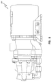
- a hydro-electric motor pump is the VICKERS® Fluid Cooled AC Motorpump (MPEVS-032Series) 500 which is illustrated in FIG. 5 and is manufactured by Eaton; this motor pump is designed to provide continuous hydraulic power for commercial and military aircraft.
- An electro-mechanical actuator 600 with a three phase motor is illustrated in FIG. 6 ; this and other types of electro-mechanical actuators suitable for aeronautic applications are also available from Eaton.
- Systems, devices or methods disclosed herein may include one or more of the features structures, methods, or combination thereof described herein.
- a device or method may be implemented to include one or more of the features and/or processes above. It is intended that such device or method need not include all of the features and/or processes described herein, but may be implemented to include selected features and/or processes that provide useful structures and/or functionality.
Landscapes
- Engineering & Computer Science (AREA)
- Power Engineering (AREA)
- Control Of Motors That Do Not Use Commutators (AREA)
- Inverter Devices (AREA)
Abstract
Description
- This application claims the benefit of
U.S. Patent Application Serial No. 62/219,388, filed September 16, 2015 - The present disclosure generally relates to pulse width modulation schemes for three-phase motors and, more particularly to pulse width modulation schemes utilizing a two-cycle pattern that employs a first reference voltage in the first cycle of the pattern and a second reference voltage in the second cycle of the pattern.
- Modern electrical machines incorporating three-phase AC or brushless DC motors, e.g., hydro-electric motor pumps, electro-mechanical actuators, etc., utilize pulse width modulation (PWM) to control the average voltage applied to the motor windings. Velocity and current control loops feed the PWM loop the necessary commands to achieve a desired velocity or current (torque). Various PWM schemes, e.g., six-step and sinusoidal, have been used in the past to produce a desired output. However, the industry trend has been migrating away from six-step (trapezoidal) and sinusoidal PWM to more mathematically complex but more efficient space vector PWM due to better performance at both low and high speed motor operation. However, the down side to both sinusoidal and space vector PWM is the significant number of switching events occurring in the power electronics; each switching event may introduce increased power losses. Further, various PWM schemes have been known to create hot spots within the power electronics by utilizing the electronics in an unevenly distributed manner. And, some PWM schemes that are utilized with traditional inverter bootstrapping gate drive topologies prevent operation at 100% PWM duty ratio.
- One aspect of this disclosure is directed to a system that includes a three phase AC or brushless DC motor, an inverter and a controller. The inverter is electrically coupled to the - motor. The controller is electrically coupled to the inverter. Further, the controller is configured to control the inverter to deliver a three phase pulse width modulated voltage to the motor, wherein the three phase pulse width modulation comprises a repeating two-cycle pattern.
- Another aspect of this disclosure is directed to controlling the voltage delivered to a three phase AC motor or brushless DC motor with pulse width modulation. The pulse width modulation is a two-cycle pulse width modulation with the first cycle being a ground reference pulse width modulation and the second cycle being a DC bus reference modulation.
- Still another aspect of this disclosure is directed to a controller. The controller includes a programmable device that is configured to execute a program of instructions. The instructions of the program direct the programmable device to control a plurality of switches in a DC powered inverter to produce an average AC voltage output. The average AC voltage output is defined by two electrical cycles. Each of the two electrical cycles uses a different reference voltage to produce the average AC output voltage.
- The above summary is not intended to describe each embodiment or every implementation. A more complete understanding will become apparent and appreciated by referring to the following detailed description and claims in conjunction with the accompanying drawings.
-
-
FIG. 1 is a block diagram illustrating a three-phase inverter circuit coupled to an AC motor. -
FIG. 2 is a timing diagram illustrating the timing of the switches ofFIG. 1 to obtain three-phase alternating current with the upper graph illustrating the time that each switch is on/off and the lower graph illustrating the average phase voltage delivered across the legs of an AC motor. -
FIGS. 3A-3D comprise a graphical illustration of a pulse width modulation (PWM) scheme configured to produce a sinusoidal average phase voltage. -
FIGS. 4A-4D comprise a graphical illustration of three-phase variable reference PWM in accordance with various embodiments of the present disclosure. -
FIG. 5 is an illustration of an example hydro-electric motor pump that may utilize a motor in combination with the three phase variable reference PWM scheme in accordance with various embodiments of the present disclosure. -
FIG. 6 is an illustration of an example electro-mechanical actuator that may utilize a motor in combination with the three phase variable reference PWM scheme in accordance with various embodiments of the present disclosure. - The figures are not necessarily to scale. Like numbers used in the figures refer to like components. However, it will be understood that the use of a number to refer to a component in a given figure is not intended to limit the component in another figure labeled with the same number.
- The present disclosure is directed to a pulse width modulation (PWM) scheme that may be utilized with three-phase AC or brushless DC motors, such as those found in hydro-electric motor pumps or electro-mechanical actuators. The present PWM scheme comprises a two-cycle pattern that employs a first reference voltage in the first cycle of the pattern and a second reference voltage in the second cycle of the pattern. The three-phase variable reference PWM scheme described herein operates to reduce inverter losses resulting in higher operating efficiencies and more even thermal heating of the power electronic devices, e.g., reduced hot spots. Moreover, the disclosed PWM scheme may be implemented within the software/firmware of an existing, or new, programmable controller, e.g., processor, microprocessor, field programmable gate array (FPGA), etc. In the instance of an existing programmable controller, no additional hardware and no additional cost is required for implementation.
- The three-phase variable reference PWM of the present disclosure may be applied to a three-phase inverter that is coupled to an AC or brushless DC motor, a simplified example of which is provided in
FIG. 1 . As shown, theinverter circuit 100 generally includes aDC power supply 102 and six switches identified as S1, S2, S3, S4, S5, and S6, which may be any type of an appropriate transistor switch such as an IGBT or MOSFET. The switches S1-S6 are coupled to a three-phase motor 104 at legs A, B and C. Aprogrammable controller 106 is electrically coupled to theinverter circuit 100 and directs the switch operation. Theprogrammable controller 106 makes use of various motor system data inputs including the DC bus voltage, the two-phase rotating reference frame voltages, which are calculated by thecontroller 106 from the three-phase AC quantities for use in subsequent calculation, and an electrical angle provided by a resolver or a rotary encoder on the motor. - In a traditional sinusoidal PWM modulation scheme, the
inverter circuit 100 ofFIG. 1 would be controlled to produce a three-phase sinusoidal output waveform. More specifically, theprogrammable controller 106 would direct the six switches to turn on and off according to a pulse diagram such as the one depicted in the upper graph ofFIG. 2 (firing angle is provided along the top of the graph). In response, theinverter circuit 100 would deliver a three-phase sinusoidal voltage across the legs of themotor 104, e.g., across A-B, B-C and C-A, as illustrated in the pulse diagram (lower graph) ofFIG. 2 - The traditional sinusoidal waveforms delivered to the
motor 104 are approximated sinusoidal waveforms generated through a PWM scheme programmed into the controller. PWM, or pulse width modulation, uses a rectangular pulse wave whose pulse width is modulated resulting in the variation of the average value of the waveform.FIGS. 3A-3D help to further illustrate this concept.FIG. 3A illustrates the average phase voltage of aninverter circuit 100 programmed to produce an approximated sinusoidal waveform.FIGS. 3B-3D illustrate various points along the waveform. For example,FIG. 3B illustrates the pulse wave of a high, average phase voltage amplitude of approximately 0.9 volts at approximately 170 deg. As shown, the width of the pulse is large to obtain the desired high, average voltage.FIG. 3C illustrates the pulse wave of a low, average phase voltage amplitude of approximately 0.1 volts at approximately 320 deg. As shown, the width of the pulse is small to obtain the desired low, average phase voltage.FIG. 3D illustrates the pulse wave of an intermediate, average phase voltage amplitude of approximately 0.5 volts at approximately 360 deg. As shown, the pulse lasts approximately half the width of the cycle to obtain the desired intermediate, average phase voltage. - With the traditional sinusoidal waveform illustrated in
FIGS. 3A-3D , each point along the curve requires multiple transitions, e.g., a switch switching on to produce the pulse and switching off to stop the pulse. Each transition introduces losses into the circuit and limits the motor efficiency. - The three-phase variable reference PWM modulation scheme of the present disclosure is configured to improve motor efficiency by reducing the number of transitions and, thereby, the losses associate with those transitions.
FIG. 4A illustrates the average phase voltage amplitude output of theinverter circuit 100 configured in accordance with the three-phase variable PWM scheme. The waveform ofFIG. 4A illustrates one complete waveform of the average phase voltage that is produced using the repeating two cycle pattern of the three-phase variable PWM scheme.FIGS. 4B-4D illustrate various points along the waveform. For example,FIG. 4B illustrates the pulse wave of a high, average phase voltage amplitude of approximately 0.75 volts at approximately 190 deg. As shown, the width of the pulse is large to obtain the desired high, average phase voltage.FIG. 4C illustrates that at an average phase voltage of approximately 0 volts and an angle of approximately 300 deg., comprises a steady voltage; no pulsing is required meaning no switches are transitioning.FIG. 4D illustrates that at the maximum average phase voltage of approximately 1 volt and an angle of approximately 400 degrees a steady voltage is supplied; once again, no pulsing is required and no switches are transitioning. - The three phase variable reference PWM scheme that produces the phase voltage amplitude output waveform of
FIG. 4A may be implemented by utilizing two equations that define the two duty cycles of the scheme. The first duty cycle, programmed within thecontroller 106 to occur between 0 deg. to 360 deg., may be deemed ground reference PWM whereby the average phase voltage amplitude during the first duty cycle is calculated in accordance with Equation (1).
- x = Phase A, B, or C voltage;
- K1 = maximum pwm count (reference: 699);
- Vdc = DC link bus voltage measurement
- The second duty cycle, programmed within the
controller 106 to occur between 360 deg. to 720 deg., may be deemed DC bus reference PWM whereby the average phase voltage amplitude during the second duty cycle is calculated in accordance with Equation (2).
- x = Phase A, B, or C voltage
- K1 = maximum pwm count (reference 699)
- Vdc = DC link bus voltage measurement
- The three phase variable reference PWM scheme described above provides for reduced three phase bridge (inverter) losses resulting in higher motor efficiency. Further, the three-phase variable PWM scheme provides for more even thermal heating of the power electronics, e.g., instances of no pulsing means no switching and, thereby, no heat generation by the switch. The more even thermal heating reduces hot spots in the power electronics and may improve longevity of the electronics. The three-phase variable PWM scheme also provides for simplified implementation through programmable equations.
- The three phase variable reference PWM scheme of the present disclosure may be used with any three phase AC or brushless DC motor. However, the scheme may be particularly suited to aeronautical applications where the three phase motor is utilized in hydro-electric motor pumps or electro-mechanical actuators. One example of a hydro-electric motor pump is the VICKERS® Fluid Cooled AC Motorpump (MPEVS-032Series) 500 which is illustrated in
FIG. 5 and is manufactured by Eaton; this motor pump is designed to provide continuous hydraulic power for commercial and military aircraft. One example of an electro-mechanical actuator 600 with a three phase motor is illustrated inFIG. 6 ; this and other types of electro-mechanical actuators suitable for aeronautic applications are also available from Eaton. - Systems, devices or methods disclosed herein may include one or more of the features structures, methods, or combination thereof described herein. For example, a device or method may be implemented to include one or more of the features and/or processes above. It is intended that such device or method need not include all of the features and/or processes described herein, but may be implemented to include selected features and/or processes that provide useful structures and/or functionality.
- Various modifications and additions can be made to the disclosed embodiments discussed above. For example, there are many variations of the three phase inverter circuit of
FIG. 1 that those skilled in the art are familiar with and to which the three phase variable reference PWM scheme of the present disclosure may be applied. Accordingly, the scope of the present disclosure should not be limited by the particular embodiments described above, but should be defined only by the claims set forth below and equivalents thereof.
Claims (15)
- A system comprising:a motor, comprising a three phase AC or brushless DC motor;an inverter electrically coupled to the AC motor; anda controller communicatively coupled to the inverter, the controller configured to control the inverter to deliver a three-phase pulse width modulated voltage to the - motor, wherein the three-phase pulse width modulation comprises a repeating two-cycle pattern.
- The system of claim 1, wherein the controller uses a first reference voltage to control the pulse width modulation in the first cycle of the pattern and a second reference voltage to control the pulse width modulation in the second cycle of the pattern, wherein the second reference voltage is different from the first reference voltage;
wherein the first reference voltage preferably comprises ground and wherein the second reference voltage preferably comprises a DC bus voltage. - The system of claim 1, wherein the first cycle of the two-cycle pattern occurs at a phase voltage angle of 0 to 360 degrees and the second cycle of the two cycle pattern occurs at a phase voltage angle of greater than 360 degrees to 720 degrees.
- The system of claim 1, wherein each cycle of the two-cycle pattern is configured to, at least at one point during the cycle, deliver an average phase voltage to the AC motor without requiring a pulsed DC voltage to produce the average phase voltage.
- The system of claim 1, wherein the motor drives a hydro-electric motor pump or an electro-mechanical actuator.
- A method comprising:controlling the voltage delivered to a motor, the motor comprising a three phase AC or brushless DC motor, with pulse width modulation, wherein the pulse width modulation comprises a two-cycle pulse width modulation, the first cycle comprising ground reference pulse width modulation and the second cycle comprising DC bus reference pulse width modulation.
- The method of claim 6, wherein the first cycle of the two-cycle pulse width modulation occurs at a phase voltage angle 0 to 360 degrees and the second cycle of the two cycle pulse width modulation occurs at a phase voltage angle of greater than 360 degrees to 720 degrees;
wherein preferably each cycle of the two-cycle pulse width modulation is controlled to, at least at one point during the cycle, deliver an average phase voltage to the - motor without requiring a pulsed DC voltage. - The method of claim 6, wherein the method comprises a hydro-electric motor pump implemented methodor an electro-mechanical actuator implemented method.
- A controller comprising:a programmable device configured to execute a program of instructions, the instructions directing the programmable device to:control a plurality of switches in a DC powered inverter to produce an average AC voltage output defined by two electrical cycles, each of the two electrical cycles using a different reference voltage to produce the average AC voltage output.
- The controller of claim 9, wherein the programmable device is selected from a field programmable gate array (FPGA) or a processor.
- The controller of claim 9, wherein the plurality of switches comprise a plurality of IGBTs or a plurality of MOSFETs.
- The controller of claim 9, wherein the first electrical cycle uses ground as a reference voltage and wherein the second electrical cycle uses a DC bus voltage as a reference.
- The controller of claim 9, wherein during the first electrical cycle all, except for the minimum, average AC voltage output is produced using a pulsed DC voltage, and wherein during the first electrical cycle the minimum average AC voltage output is produced without a pulsed DC voltage.
- The controller of claim 9, wherein during the second electrical cycle all, except for the maximum, average AC voltage output is produced using a pulsed DC voltage, and wherein during the second electrical cycle the maximum average AC voltage output is produced without a pulsed DC voltage.
- The controller of claim 9, wherein the controller comprises hydro-electric motor pump motor controller. or an an electro-mechanical actuator motor controller.
Applications Claiming Priority (2)
| Application Number | Priority Date | Filing Date | Title |
|---|---|---|---|
| US201562219388P | 2015-09-16 | 2015-09-16 | |
| US15/251,186 US10284129B2 (en) | 2015-09-16 | 2016-08-30 | Three-phase variable reference pulse width modulation |
Publications (2)
| Publication Number | Publication Date |
|---|---|
| EP3145075A1 true EP3145075A1 (en) | 2017-03-22 |
| EP3145075B1 EP3145075B1 (en) | 2024-10-30 |
Family
ID=56926084
Family Applications (1)
| Application Number | Title | Priority Date | Filing Date |
|---|---|---|---|
| EP16188688.2A Active EP3145075B1 (en) | 2015-09-16 | 2016-09-14 | Three-phase variable reference pulse width modulation |
Country Status (2)
| Country | Link |
|---|---|
| US (1) | US10284129B2 (en) |
| EP (1) | EP3145075B1 (en) |
Families Citing this family (2)
| Publication number | Priority date | Publication date | Assignee | Title |
|---|---|---|---|---|
| FR3056555B1 (en) * | 2016-09-29 | 2018-12-07 | Safran Helicopter Engines | HYBRID PROPULSIVE SYSTEM FOR MULTIROTOR ROTARY FLYWELL AIRCRAFT COMPRISING IMPROVED DC / AC CONVERSION MEANS |
| US12407286B2 (en) | 2023-03-22 | 2025-09-02 | Hamilton Sundstrand Corporation | Current limit strategy for hoist application |
Citations (3)
| Publication number | Priority date | Publication date | Assignee | Title |
|---|---|---|---|---|
| US20050194925A1 (en) * | 2004-02-10 | 2005-09-08 | Denso Corporation | Apparatus for controlling three-phase AC motor on two-phase modulation technique |
| EP2503680A2 (en) * | 2011-03-24 | 2012-09-26 | Daihen Corporation | Control circuit for controlling power conversion circuit, inverter apparatus including the control circuit, and interconnection inverter system including inverter apparatus |
| US20130330207A1 (en) * | 2012-06-08 | 2013-12-12 | Nabtesco Corporation | Aircraft motor drive control apparatus and aircraft actuator hydraulic system |
Family Cites Families (4)
| Publication number | Priority date | Publication date | Assignee | Title |
|---|---|---|---|---|
| US20010048278A1 (en) * | 1999-02-04 | 2001-12-06 | Glen C. Young | Cross coupled motor gate drive |
| KR100655917B1 (en) * | 2000-02-28 | 2006-12-08 | 가부시키가이샤 야스가와덴끼 | PWM pulse control method |
| US20060071627A1 (en) * | 2002-03-28 | 2006-04-06 | Ho Eddy Y Y | Motor current reconstruction via DC bus current measurement |
| ITVA20070010A1 (en) * | 2007-01-17 | 2008-07-18 | St Microelectronics Srl | METHOD AND RELATIVE DEVICE FOR DETERMINING THE THREE DUTY CYCLE OF INVERTER PWM SIGNALS |
-
2016
- 2016-08-30 US US15/251,186 patent/US10284129B2/en active Active
- 2016-09-14 EP EP16188688.2A patent/EP3145075B1/en active Active
Patent Citations (3)
| Publication number | Priority date | Publication date | Assignee | Title |
|---|---|---|---|---|
| US20050194925A1 (en) * | 2004-02-10 | 2005-09-08 | Denso Corporation | Apparatus for controlling three-phase AC motor on two-phase modulation technique |
| EP2503680A2 (en) * | 2011-03-24 | 2012-09-26 | Daihen Corporation | Control circuit for controlling power conversion circuit, inverter apparatus including the control circuit, and interconnection inverter system including inverter apparatus |
| US20130330207A1 (en) * | 2012-06-08 | 2013-12-12 | Nabtesco Corporation | Aircraft motor drive control apparatus and aircraft actuator hydraulic system |
Also Published As
| Publication number | Publication date |
|---|---|
| US10284129B2 (en) | 2019-05-07 |
| EP3145075B1 (en) | 2024-10-30 |
| US20170077856A1 (en) | 2017-03-16 |
Similar Documents
| Publication | Publication Date | Title |
|---|---|---|
| JP5178799B2 (en) | Motor control device | |
| KR100800901B1 (en) | Motor control unit | |
| CN105827164B (en) | Current of electric control device and current of electric control method | |
| CN105610363A (en) | Method and apparatus for controlling an electric machine in a six-step mode | |
| CN110707987A (en) | Method and apparatus for controlling cascaded inverter circuits and electric machines | |
| EP4224700B1 (en) | Software-controlled electronic circuit for switching power to a three-phase motor | |
| CN110729944A (en) | Inverter control apparatus and method for driving motor | |
| US7432683B2 (en) | PWM pattern sequence to reduce losses in voltage source inverters | |
| KR20110005674A (en) | Motor driven control unit | |
| CN102624298B (en) | Motor | |
| EP3145075B1 (en) | Three-phase variable reference pulse width modulation | |
| JP2016195514A (en) | Controller of rotary electric machine | |
| US10333428B2 (en) | Resonant load power conversion device and time division operation method for resonant load power conversion device | |
| CN106575932A (en) | Motor control apparatus, motor control method and motor control system | |
| EP0769843A1 (en) | A method and apparatus for controlling static electronic components for phase switching in a three-phase brushless electric motor | |
| US10944351B2 (en) | Motor drive control device and motor drive control method | |
| US10050569B2 (en) | Inverter control device and inverter control method | |
| EP2665178A2 (en) | System and method for sensor-less hysteresis current control of permanent magnet synchronous generators without rotor position information | |
| JPWO2015083477A1 (en) | Electric motor drive | |
| KR20200001734A (en) | Motor drive device and system | |
| EP4054069A1 (en) | Power conversion device and electric device | |
| EP3762191B1 (en) | Time-spread control cycles for robotic servomotors | |
| US20240305225A1 (en) | Motor driving device | |
| US7804264B2 (en) | Commutation method and apparatus for a DC to AC inverter driving a three-phase asynchronous AC motor | |
| JP2015033204A (en) | Motor control device |
Legal Events
| Date | Code | Title | Description |
|---|---|---|---|
| PUAI | Public reference made under article 153(3) epc to a published international application that has entered the european phase |
Free format text: ORIGINAL CODE: 0009012 |
|
| STAA | Information on the status of an ep patent application or granted ep patent |
Free format text: STATUS: THE APPLICATION HAS BEEN PUBLISHED |
|
| AK | Designated contracting states |
Kind code of ref document: A1 Designated state(s): AL AT BE BG CH CY CZ DE DK EE ES FI FR GB GR HR HU IE IS IT LI LT LU LV MC MK MT NL NO PL PT RO RS SE SI SK SM TR |
|
| AX | Request for extension of the european patent |
Extension state: BA ME |
|
| STAA | Information on the status of an ep patent application or granted ep patent |
Free format text: STATUS: REQUEST FOR EXAMINATION WAS MADE |
|
| 17P | Request for examination filed |
Effective date: 20170920 |
|
| RBV | Designated contracting states (corrected) |
Designated state(s): AL AT BE BG CH CY CZ DE DK EE ES FI FR GB GR HR HU IE IS IT LI LT LU LV MC MK MT NL NO PL PT RO RS SE SI SK SM TR |
|
| STAA | Information on the status of an ep patent application or granted ep patent |
Free format text: STATUS: EXAMINATION IS IN PROGRESS |
|
| 17Q | First examination report despatched |
Effective date: 20200210 |
|
| RAP1 | Party data changed (applicant data changed or rights of an application transferred) |
Owner name: EATON INTELLIGENT POWER LIMITED |
|
| RIC1 | Information provided on ipc code assigned before grant |
Ipc: H02M 7/48 20070101ALN20230503BHEP Ipc: H02M 7/5387 20070101ALI20230503BHEP Ipc: H02P 27/08 20060101ALI20230503BHEP Ipc: H02P 27/04 20160101AFI20230503BHEP |
|
| GRAP | Despatch of communication of intention to grant a patent |
Free format text: ORIGINAL CODE: EPIDOSNIGR1 |
|
| STAA | Information on the status of an ep patent application or granted ep patent |
Free format text: STATUS: GRANT OF PATENT IS INTENDED |
|
| RIC1 | Information provided on ipc code assigned before grant |
Ipc: H02M 7/48 20070101ALN20240319BHEP Ipc: H02M 7/5387 20070101ALI20240319BHEP Ipc: H02P 27/08 20060101ALI20240319BHEP Ipc: H02P 27/04 20160101AFI20240319BHEP |
|
| INTG | Intention to grant announced |
Effective date: 20240410 |
|
| GRAS | Grant fee paid |
Free format text: ORIGINAL CODE: EPIDOSNIGR3 |
|
| GRAA | (expected) grant |
Free format text: ORIGINAL CODE: 0009210 |
|
| STAA | Information on the status of an ep patent application or granted ep patent |
Free format text: STATUS: THE PATENT HAS BEEN GRANTED |
|
| AK | Designated contracting states |
Kind code of ref document: B1 Designated state(s): AL AT BE BG CH CY CZ DE DK EE ES FI FR GB GR HR HU IE IS IT LI LT LU LV MC MK MT NL NO PL PT RO RS SE SI SK SM TR |
|
| REG | Reference to a national code |
Ref country code: GB Ref legal event code: FG4D |
|
| REG | Reference to a national code |
Ref country code: CH Ref legal event code: EP |
|
| REG | Reference to a national code |
Ref country code: DE Ref legal event code: R096 Ref document number: 602016090014 Country of ref document: DE |
|
| REG | Reference to a national code |
Ref country code: IE Ref legal event code: FG4D |
|
| REG | Reference to a national code |
Ref country code: LT Ref legal event code: MG9D |
|
| REG | Reference to a national code |
Ref country code: NL Ref legal event code: MP Effective date: 20241030 |
|
| PG25 | Lapsed in a contracting state [announced via postgrant information from national office to epo] |
Ref country code: IS Free format text: LAPSE BECAUSE OF FAILURE TO SUBMIT A TRANSLATION OF THE DESCRIPTION OR TO PAY THE FEE WITHIN THE PRESCRIBED TIME-LIMIT Effective date: 20250228 Ref country code: HR Free format text: LAPSE BECAUSE OF FAILURE TO SUBMIT A TRANSLATION OF THE DESCRIPTION OR TO PAY THE FEE WITHIN THE PRESCRIBED TIME-LIMIT Effective date: 20241030 Ref country code: PT Free format text: LAPSE BECAUSE OF FAILURE TO SUBMIT A TRANSLATION OF THE DESCRIPTION OR TO PAY THE FEE WITHIN THE PRESCRIBED TIME-LIMIT Effective date: 20250228 |
|
| PG25 | Lapsed in a contracting state [announced via postgrant information from national office to epo] |
Ref country code: FI Free format text: LAPSE BECAUSE OF FAILURE TO SUBMIT A TRANSLATION OF THE DESCRIPTION OR TO PAY THE FEE WITHIN THE PRESCRIBED TIME-LIMIT Effective date: 20241030 Ref country code: NL Free format text: LAPSE BECAUSE OF FAILURE TO SUBMIT A TRANSLATION OF THE DESCRIPTION OR TO PAY THE FEE WITHIN THE PRESCRIBED TIME-LIMIT Effective date: 20241030 |
|
| REG | Reference to a national code |
Ref country code: AT Ref legal event code: MK05 Ref document number: 1737911 Country of ref document: AT Kind code of ref document: T Effective date: 20241030 |
|
| PG25 | Lapsed in a contracting state [announced via postgrant information from national office to epo] |
Ref country code: BG Free format text: LAPSE BECAUSE OF FAILURE TO SUBMIT A TRANSLATION OF THE DESCRIPTION OR TO PAY THE FEE WITHIN THE PRESCRIBED TIME-LIMIT Effective date: 20241030 |
|
| PG25 | Lapsed in a contracting state [announced via postgrant information from national office to epo] |
Ref country code: ES Free format text: LAPSE BECAUSE OF FAILURE TO SUBMIT A TRANSLATION OF THE DESCRIPTION OR TO PAY THE FEE WITHIN THE PRESCRIBED TIME-LIMIT Effective date: 20241030 |
|
| PG25 | Lapsed in a contracting state [announced via postgrant information from national office to epo] |
Ref country code: NO Free format text: LAPSE BECAUSE OF FAILURE TO SUBMIT A TRANSLATION OF THE DESCRIPTION OR TO PAY THE FEE WITHIN THE PRESCRIBED TIME-LIMIT Effective date: 20250130 |
|
| PG25 | Lapsed in a contracting state [announced via postgrant information from national office to epo] |
Ref country code: LV Free format text: LAPSE BECAUSE OF FAILURE TO SUBMIT A TRANSLATION OF THE DESCRIPTION OR TO PAY THE FEE WITHIN THE PRESCRIBED TIME-LIMIT Effective date: 20241030 Ref country code: GR Free format text: LAPSE BECAUSE OF FAILURE TO SUBMIT A TRANSLATION OF THE DESCRIPTION OR TO PAY THE FEE WITHIN THE PRESCRIBED TIME-LIMIT Effective date: 20250131 Ref country code: AT Free format text: LAPSE BECAUSE OF FAILURE TO SUBMIT A TRANSLATION OF THE DESCRIPTION OR TO PAY THE FEE WITHIN THE PRESCRIBED TIME-LIMIT Effective date: 20241030 |
|
| PG25 | Lapsed in a contracting state [announced via postgrant information from national office to epo] |
Ref country code: PL Free format text: LAPSE BECAUSE OF FAILURE TO SUBMIT A TRANSLATION OF THE DESCRIPTION OR TO PAY THE FEE WITHIN THE PRESCRIBED TIME-LIMIT Effective date: 20241030 |
|
| PG25 | Lapsed in a contracting state [announced via postgrant information from national office to epo] |
Ref country code: RS Free format text: LAPSE BECAUSE OF FAILURE TO SUBMIT A TRANSLATION OF THE DESCRIPTION OR TO PAY THE FEE WITHIN THE PRESCRIBED TIME-LIMIT Effective date: 20250130 |
|
| PG25 | Lapsed in a contracting state [announced via postgrant information from national office to epo] |
Ref country code: SM Free format text: LAPSE BECAUSE OF FAILURE TO SUBMIT A TRANSLATION OF THE DESCRIPTION OR TO PAY THE FEE WITHIN THE PRESCRIBED TIME-LIMIT Effective date: 20241030 |
|
| PG25 | Lapsed in a contracting state [announced via postgrant information from national office to epo] |
Ref country code: DK Free format text: LAPSE BECAUSE OF FAILURE TO SUBMIT A TRANSLATION OF THE DESCRIPTION OR TO PAY THE FEE WITHIN THE PRESCRIBED TIME-LIMIT Effective date: 20241030 |
|
| PG25 | Lapsed in a contracting state [announced via postgrant information from national office to epo] |
Ref country code: EE Free format text: LAPSE BECAUSE OF FAILURE TO SUBMIT A TRANSLATION OF THE DESCRIPTION OR TO PAY THE FEE WITHIN THE PRESCRIBED TIME-LIMIT Effective date: 20241030 |
|
| PG25 | Lapsed in a contracting state [announced via postgrant information from national office to epo] |
Ref country code: RO Free format text: LAPSE BECAUSE OF FAILURE TO SUBMIT A TRANSLATION OF THE DESCRIPTION OR TO PAY THE FEE WITHIN THE PRESCRIBED TIME-LIMIT Effective date: 20241030 |
|
| PG25 | Lapsed in a contracting state [announced via postgrant information from national office to epo] |
Ref country code: SK Free format text: LAPSE BECAUSE OF FAILURE TO SUBMIT A TRANSLATION OF THE DESCRIPTION OR TO PAY THE FEE WITHIN THE PRESCRIBED TIME-LIMIT Effective date: 20241030 |
|
| PG25 | Lapsed in a contracting state [announced via postgrant information from national office to epo] |
Ref country code: CZ Free format text: LAPSE BECAUSE OF FAILURE TO SUBMIT A TRANSLATION OF THE DESCRIPTION OR TO PAY THE FEE WITHIN THE PRESCRIBED TIME-LIMIT Effective date: 20241030 |
|
| PG25 | Lapsed in a contracting state [announced via postgrant information from national office to epo] |
Ref country code: IT Free format text: LAPSE BECAUSE OF FAILURE TO SUBMIT A TRANSLATION OF THE DESCRIPTION OR TO PAY THE FEE WITHIN THE PRESCRIBED TIME-LIMIT Effective date: 20241030 |
|
| REG | Reference to a national code |
Ref country code: DE Ref legal event code: R097 Ref document number: 602016090014 Country of ref document: DE |
|
| PLBE | No opposition filed within time limit |
Free format text: ORIGINAL CODE: 0009261 |
|
| STAA | Information on the status of an ep patent application or granted ep patent |
Free format text: STATUS: NO OPPOSITION FILED WITHIN TIME LIMIT |
|
| PG25 | Lapsed in a contracting state [announced via postgrant information from national office to epo] |
Ref country code: SE Free format text: LAPSE BECAUSE OF FAILURE TO SUBMIT A TRANSLATION OF THE DESCRIPTION OR TO PAY THE FEE WITHIN THE PRESCRIBED TIME-LIMIT Effective date: 20241030 |
|
| 26N | No opposition filed |
Effective date: 20250731 |
|
| PGFP | Annual fee paid to national office [announced via postgrant information from national office to epo] |
Ref country code: DE Payment date: 20250820 Year of fee payment: 10 |
|
| PGFP | Annual fee paid to national office [announced via postgrant information from national office to epo] |
Ref country code: GB Payment date: 20250822 Year of fee payment: 10 |
|
| PGFP | Annual fee paid to national office [announced via postgrant information from national office to epo] |
Ref country code: FR Payment date: 20250820 Year of fee payment: 10 |
|
| REG | Reference to a national code |
Ref country code: CH Ref legal event code: H13 Free format text: ST27 STATUS EVENT CODE: U-0-0-H10-H13 (AS PROVIDED BY THE NATIONAL OFFICE) Effective date: 20260425 |