EP3145029A1 - Socket - Google Patents
Socket Download PDFInfo
- Publication number
- EP3145029A1 EP3145029A1 EP16185909.5A EP16185909A EP3145029A1 EP 3145029 A1 EP3145029 A1 EP 3145029A1 EP 16185909 A EP16185909 A EP 16185909A EP 3145029 A1 EP3145029 A1 EP 3145029A1
- Authority
- EP
- European Patent Office
- Prior art keywords
- spring member
- base
- position restricting
- socket
- bracket
- Prior art date
- Legal status (The legal status is an assumption and is not a legal conclusion. Google has not performed a legal analysis and makes no representation as to the accuracy of the status listed.)
- Granted
Links
Images




Classifications
-
- H—ELECTRICITY
- H01—ELECTRIC ELEMENTS
- H01R—ELECTRICALLY-CONDUCTIVE CONNECTIONS; STRUCTURAL ASSOCIATIONS OF A PLURALITY OF MUTUALLY-INSULATED ELECTRICAL CONNECTING ELEMENTS; COUPLING DEVICES; CURRENT COLLECTORS
- H01R13/00—Details of coupling devices of the kinds covered by groups H01R12/70 or H01R24/00 - H01R33/00
- H01R13/40—Securing contact members in or to a base or case; Insulating of contact members
-
- H—ELECTRICITY
- H01—ELECTRIC ELEMENTS
- H01R—ELECTRICALLY-CONDUCTIVE CONNECTIONS; STRUCTURAL ASSOCIATIONS OF A PLURALITY OF MUTUALLY-INSULATED ELECTRICAL CONNECTING ELEMENTS; COUPLING DEVICES; CURRENT COLLECTORS
- H01R13/00—Details of coupling devices of the kinds covered by groups H01R12/70 or H01R24/00 - H01R33/00
- H01R13/02—Contact members
- H01R13/10—Sockets for co-operation with pins or blades
-
- H—ELECTRICITY
- H01—ELECTRIC ELEMENTS
- H01R—ELECTRICALLY-CONDUCTIVE CONNECTIONS; STRUCTURAL ASSOCIATIONS OF A PLURALITY OF MUTUALLY-INSULATED ELECTRICAL CONNECTING ELEMENTS; COUPLING DEVICES; CURRENT COLLECTORS
- H01R13/00—Details of coupling devices of the kinds covered by groups H01R12/70 or H01R24/00 - H01R33/00
- H01R13/02—Contact members
- H01R13/22—Contacts for co-operating by abutting
- H01R13/24—Contacts for co-operating by abutting resilient; resiliently-mounted
- H01R13/2407—Contacts for co-operating by abutting resilient; resiliently-mounted characterized by the resilient means
- H01R13/2428—Contacts for co-operating by abutting resilient; resiliently-mounted characterized by the resilient means using meander springs
-
- H—ELECTRICITY
- H01—ELECTRIC ELEMENTS
- H01R—ELECTRICALLY-CONDUCTIVE CONNECTIONS; STRUCTURAL ASSOCIATIONS OF A PLURALITY OF MUTUALLY-INSULATED ELECTRICAL CONNECTING ELEMENTS; COUPLING DEVICES; CURRENT COLLECTORS
- H01R4/00—Electrically-conductive connections between two or more conductive members in direct contact, i.e. touching one another; Means for effecting or maintaining such contact; Electrically-conductive connections having two or more spaced connecting locations for conductors and using contact members penetrating insulation
- H01R4/28—Clamped connections, spring connections
- H01R4/48—Clamped connections, spring connections utilising a spring, clip, or other resilient member
-
- H—ELECTRICITY
- H01—ELECTRIC ELEMENTS
- H01R—ELECTRICALLY-CONDUCTIVE CONNECTIONS; STRUCTURAL ASSOCIATIONS OF A PLURALITY OF MUTUALLY-INSULATED ELECTRICAL CONNECTING ELEMENTS; COUPLING DEVICES; CURRENT COLLECTORS
- H01R4/00—Electrically-conductive connections between two or more conductive members in direct contact, i.e. touching one another; Means for effecting or maintaining such contact; Electrically-conductive connections having two or more spaced connecting locations for conductors and using contact members penetrating insulation
- H01R4/28—Clamped connections, spring connections
- H01R4/48—Clamped connections, spring connections utilising a spring, clip, or other resilient member
- H01R4/4809—Clamped connections, spring connections utilising a spring, clip, or other resilient member using a leaf spring to bias the conductor toward the busbar
- H01R4/48185—Clamped connections, spring connections utilising a spring, clip, or other resilient member using a leaf spring to bias the conductor toward the busbar adapted for axial insertion of a wire end
- H01R4/4819—Clamped connections, spring connections utilising a spring, clip, or other resilient member using a leaf spring to bias the conductor toward the busbar adapted for axial insertion of a wire end the spring shape allowing insertion of the conductor end when the spring is unbiased
- H01R4/4821—Single-blade spring
-
- H—ELECTRICITY
- H01—ELECTRIC ELEMENTS
- H01R—ELECTRICALLY-CONDUCTIVE CONNECTIONS; STRUCTURAL ASSOCIATIONS OF A PLURALITY OF MUTUALLY-INSULATED ELECTRICAL CONNECTING ELEMENTS; COUPLING DEVICES; CURRENT COLLECTORS
- H01R13/00—Details of coupling devices of the kinds covered by groups H01R12/70 or H01R24/00 - H01R33/00
- H01R13/46—Bases; Cases
- H01R13/502—Bases; Cases composed of different pieces
- H01R13/506—Bases; Cases composed of different pieces assembled by snap action of the parts
-
- H—ELECTRICITY
- H01—ELECTRIC ELEMENTS
- H01R—ELECTRICALLY-CONDUCTIVE CONNECTIONS; STRUCTURAL ASSOCIATIONS OF A PLURALITY OF MUTUALLY-INSULATED ELECTRICAL CONNECTING ELEMENTS; COUPLING DEVICES; CURRENT COLLECTORS
- H01R13/00—Details of coupling devices of the kinds covered by groups H01R12/70 or H01R24/00 - H01R33/00
- H01R13/56—Means for preventing chafing or fracture of flexible leads at outlet from coupling part
- H01R13/562—Bending-relieving
-
- H—ELECTRICITY
- H01—ELECTRIC ELEMENTS
- H01R—ELECTRICALLY-CONDUCTIVE CONNECTIONS; STRUCTURAL ASSOCIATIONS OF A PLURALITY OF MUTUALLY-INSULATED ELECTRICAL CONNECTING ELEMENTS; COUPLING DEVICES; CURRENT COLLECTORS
- H01R13/00—Details of coupling devices of the kinds covered by groups H01R12/70 or H01R24/00 - H01R33/00
- H01R13/58—Means for relieving strain on wire connection, e.g. cord grip, for avoiding loosening of connections between wires and terminals within a coupling device terminating a cable
-
- H—ELECTRICITY
- H01—ELECTRIC ELEMENTS
- H01R—ELECTRICALLY-CONDUCTIVE CONNECTIONS; STRUCTURAL ASSOCIATIONS OF A PLURALITY OF MUTUALLY-INSULATED ELECTRICAL CONNECTING ELEMENTS; COUPLING DEVICES; CURRENT COLLECTORS
- H01R4/00—Electrically-conductive connections between two or more conductive members in direct contact, i.e. touching one another; Means for effecting or maintaining such contact; Electrically-conductive connections having two or more spaced connecting locations for conductors and using contact members penetrating insulation
- H01R4/28—Clamped connections, spring connections
- H01R4/48—Clamped connections, spring connections utilising a spring, clip, or other resilient member
- H01R4/4809—Clamped connections, spring connections utilising a spring, clip, or other resilient member using a leaf spring to bias the conductor toward the busbar
- H01R4/484—Spring housing details
- H01R4/4842—Spring housing details the spring housing being provided with a single opening for insertion of a spring-activating tool
-
- H—ELECTRICITY
- H01—ELECTRIC ELEMENTS
- H01R—ELECTRICALLY-CONDUCTIVE CONNECTIONS; STRUCTURAL ASSOCIATIONS OF A PLURALITY OF MUTUALLY-INSULATED ELECTRICAL CONNECTING ELEMENTS; COUPLING DEVICES; CURRENT COLLECTORS
- H01R4/00—Electrically-conductive connections between two or more conductive members in direct contact, i.e. touching one another; Means for effecting or maintaining such contact; Electrically-conductive connections having two or more spaced connecting locations for conductors and using contact members penetrating insulation
- H01R4/28—Clamped connections, spring connections
- H01R4/48—Clamped connections, spring connections utilising a spring, clip, or other resilient member
- H01R4/4809—Clamped connections, spring connections utilising a spring, clip, or other resilient member using a leaf spring to bias the conductor toward the busbar
- H01R4/4846—Busbar details
- H01R4/485—Single busbar common to multiple springs
-
- H—ELECTRICITY
- H01—ELECTRIC ELEMENTS
- H01R—ELECTRICALLY-CONDUCTIVE CONNECTIONS; STRUCTURAL ASSOCIATIONS OF A PLURALITY OF MUTUALLY-INSULATED ELECTRICAL CONNECTING ELEMENTS; COUPLING DEVICES; CURRENT COLLECTORS
- H01R4/00—Electrically-conductive connections between two or more conductive members in direct contact, i.e. touching one another; Means for effecting or maintaining such contact; Electrically-conductive connections having two or more spaced connecting locations for conductors and using contact members penetrating insulation
- H01R4/28—Clamped connections, spring connections
- H01R4/50—Clamped connections, spring connections utilising a cam, wedge, cone or ball also combined with a screw
- H01R4/52—Clamped connections, spring connections utilising a cam, wedge, cone or ball also combined with a screw which is spring loaded
-
- H—ELECTRICITY
- H01—ELECTRIC ELEMENTS
- H01R—ELECTRICALLY-CONDUCTIVE CONNECTIONS; STRUCTURAL ASSOCIATIONS OF A PLURALITY OF MUTUALLY-INSULATED ELECTRICAL CONNECTING ELEMENTS; COUPLING DEVICES; CURRENT COLLECTORS
- H01R9/00—Structural associations of a plurality of mutually-insulated electrical connecting elements, e.g. terminal strips or terminal blocks; Terminals or binding posts mounted upon a base or in a case; Bases therefor
- H01R9/22—Bases, e.g. strip, block, panel
- H01R9/24—Terminal blocks
Definitions
- the present invention relates to a socket and, more particularly, relates to a socket which connects leads by using an operation driver.
- a socket which connects leads by using an operation driver is formed by, for example, assembling in a housing a connection fitting including a bracket and a spring member. Further, there is a socket which causes the operation driver inserted in the housing to elastically deform the spring member to sandwich the leads between the bracket and the spring member (see German Patent No. 102009004513 ).
- the socket has a problem that, when an operation driver 56 is inserted in a housing 52 to elastically deform a spring member 10 as shown in Fig. 10 , the operation driver 56 is erroneously operated and the spring member 10 is plastically deformed.
- an object of a socket according to the present invention is to provide a socket which prevents plastic deformation of a spring member of a connection fitting.
- a socket according to the present invention is a socket including a base and a connection fitting including a bracket and a spring member and assembled to an upper surface of the base, the spring member of the connection fitting being pressed and elastically deformed to sandwich a lead between the bracket and the spring member, in which a position restricting protrusion configured to come into contact with the pressed and deformed spring member and prevent plastic deformation is protruded on the upper surface of the base.
- the present invention can provide a socket which can prevent plastic deformation of the spring member since, when the operation driver presses and deforms the spring member, the spring member comes into contact with the position restricting protrusion and a position of the spring member is restricted.
- the position restricting protrusion may be integrally molded with the base.
- a position restricting tapered surface which the spring member comes into planar contact with may be formed at an upper end of the position restricting protrusion.
- the spring member comes into planar contact with the position restricting tapered surface of the position restricting protrusion, and the position of the spring member is restricted. Consequently, it is possible to provide a socket which hardly causes stress concentration and whose spring member is more hardly plastically deformed.
- a fitting hole configured to fit to the position restricting protrusion protruded from the base may be provided to the bracket of the connection fitting.
- the bracket can be accurately assembled to the base via the position restricting protrusion of the base, so that it is possible to obtain a socket of high assembly precision.
- a guide partition wall may be bridged between and integrally molded with a ceiling surface and an inside surface of a case cover of a box shape configured to fit to the base and cover the connection fitting, the guide partition wall may engage with a slit provided to the bracket and the spring member of the connection fitting, and an operation driver inserted along the guide partition wall through an operation hole provided on the ceiling surface of the case cover may press and elastically deform a pressure spring of the spring member.
- the guide partition wall bridged between and integrally molded with the ceiling surface and the inside surface of the case cover engages with the slit provided to the bracket and the spring member of the connection fitting.
- the guide partition wall partitions neighboring pressure springs of the spring member.
- the guide partition wall is bridged between and integrally molded with the ceiling surface and the inside surface of the case cover. Hence, even when the operation driver is erroneously inserted, the guide partition wall is not broken, and broken pieces are not produced. As a result, it is possible to provide a socket which does not cause connection failure caused by the broken pieces.
- a notch configured to engage with the position restricting protrusion provided to the base may be formed at a lower end rim of the guide partition wall.
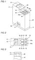
- the socket according to a first embodiment is formed by a base 10, a connection fitting 20 and a case cover 40 as shown in the accompanying drawings of Figs. 1 to 10 .
- a seating 11 is protruded from an upper surface of the base 10 to form an annular step 12.
- a connection hole 13 is provided in an upper surface 11 a which is one step lower in the upper surface of the seating 11.
- a support protrusion 14 is protruded at a rim of an upper surface 11 b which is one step higher in the upper surface of the seating 11.
- a position restricting protrusion 15 is integrally molded with a nearly center of the upper surface 11 b.
- the position restricting protrusion 15 includes a position restricting tapered surface 16 at an upper end of the position restricting protrusion 15. Further, engagement claws 17 and 17 are protruded along a longitudinal direction of the seating 11 and on opposing outside surfaces.
- the position restricting protrusion 15 is integrally molded with the base 10, and the connection fitting 20 described below is assembled to the base 10.
- precision to position the connection fitting 20 is high, and an assembly error is little.
- an operation driver presses pressure springs 35 of the connection fitting 20
- a pressing position does not vary, so that it is possible to effectively prevent occurrence of plastic deformation.
- the position restricting tapered surface 16 has an inclined angle which can come into planar contact with the pressure springs 35 when the pressure springs 35 of the connection fitting 20 described below elastically deform. Consequently, it is possible to effectively prevent plastic deformation of the pressure springs 35.
- connection fitting 20 is formed by a bracket 21 and a spring member 30 whose sectional shape is a nearly V shape.
- a retaining portion 22 is formed at one side of the bracket 21 provided with a through-hole 21 a by bending a conductive metal plate by way of press working, and a caulked portion 23, a bottom portion 24 and a pressure contact portion 25 are formed at the other side.
- the retaining portion 22 has a shape which can retain leads which are not shown by way of caulking work.
- the caulked portion 23 is formed by having a plurality of caulking projections 26 project from a surface of the caulked portion 23, and a square fitting hole 27 is formed in the bottom portion 24. Furthermore, a pair of pressure contact receiving portions 29 and 29 are formed by dividing the pressure contact portion 25 into two in the width direction by a slit 28 formed at a free end of the pressure contact portion 25.
- the spring member 30 is bent in a nearly V shape, and has pluralities of caulking small holes 32 and caulking large holes 33 at the caulked portion 31 at one side of the spring member 30. Further, the spring member 30 has a slit 34 at a free end which elastically deforms at the other side of the spring member 30 to form a pair of pressure springs 35 and 35. Furthermore, by caulking and fixing the caulking small holes 32 and the caulking large holes 33 of the spring member 30 to the caulking projections 26 and 26 of the bracket 21, leading end portions of the pressure springs 35 and 35 of the spring member 30 come into pressure contact with the pressure contact receiving portions 29 and 29 of the bracket 21.
- the fitting hole 27 provided to the bottom portion 24 of the bracket 21 is fitted to and assembled to the position restricting protrusion 15 of the base 10. Further, leads which are not shown and are inserted from a lower side via the connection hole 13 of the base 10 are caulked and fixed to and are electrically connected to the retaining portion 22 of the bracket 21.
- the case cover 40 has a box shape which can fit to the annular step 12 of the base 10, and has a step shape including a step 41 at a single side of an upper surface of the box shape. Further, at a position corresponding to an upper end surface of the support protrusion 14 of the base 10 on an upper surface of the step 41, a recessed portion 42 is formed. Furthermore, at a bottom surface of the recessed portion 42, a through-hole 43 ( Fig. 5 ) continuing to the through-hole 21 a of the bracket 21 is formed. Hence, the bracket 21 can be electrically connected to the bracket 21 of another neighboring socket (not shown) via the through-hole 43 of the case cover 40.
- the case cover 40 has an operation hole 44 in which the operation driver not shown can be inserted. Furthermore, at a position corresponding to free ends of the pressure springs 35, insertion holes 45 in which leads can be inserted are formed. At an opening rim of each insertion hole 45, a chamfered portion 45a which makes it easy to insert leads is formed.
- a guide notch 46 having substantially a semi-arc surface is formed to guide the operation driver which is inserted in the operation hole 44.
- the case cover 40 is integrally molded with a guide partition wall 47 to bridge the guide partition wall 47 between a ceiling surface and an inside surface of the case cover 40.
- the guide partition wall 47 may engage with the slit 28 provided to the bracket 21 and the slit 34 of the spring member 30.
- the guide partition wall 47 includes at a lower end rim of the guide partition wall 47 a notch 48 ( Fig. 5 ) which engages with the position restricting protrusion 15 of the base 10.
- case cover 40 includes engagement holes 49 ( Fig. 6 ) which engage with the engagement claws 17 of the base 10 in opposing side surfaces.
- the engagement holes 49 of the case cover 40 engage with and are integrally formed with the engagement claws 17 of the base 10 ( Fig. 1 ).
- the guide partition wall 47 of the case cover 40 engages with the slit 28 of the bracket 21 and the slit 34 of the spring member 30 ( Fig. 4 ).
- the notch 48 of the guide partition wall 47 engages with the position restricting protrusion 15 of the base 10 to partition the pressure springs 35 and 35.
- an operation driver 50 is inserted in the operation hole 44 to press the intermediate area of the pressure springs 35 and push down the pressure springs 35. Subsequently, the lead inserted through the insertion hole 45 is positioned between the leading end portions of the pressure springs 35 and the pressure contact receiving portions 29. Then, when the operation driver 50 is pulled, the pressure springs 35 are elastically restored, and the leading end portions of the pressure springs 35 and the pressure contact receiving portions 29 sandwich the lead.
- the operation driver 50 is inserted in the operation hole 44 to press the intermediate area of the pressure springs 35 and push down the pressure springs 35, so that it is possible to detach the lead.
- the positions of the pressure springs 35 are restricted by the position restricting tapered surface 16 of the position restricting protrusion 15. Consequently, it is possible to prevent plastic deformation of the pressure springs 35.
- a socket according to a second embodiment is substantially the same as that of the first embodiment as shown in Figs. 11 to 14 , and differs from the first embodiment in that a guide notch 46 provided to a step 41 of a case cover 40 is formed by a pair of flat and triangular tapered surfaces.
- the guide notch 46 is formed by a pair of flat and triangular tapered surfaces. Consequently, by inserting an operation driver (not shown) along the guide notch 46, it is easy to position the operation driver. As a result, the operation driver can accurately and quickly operate the pressure springs 35.
- FIG. 15 and 16 A stress distribution was analyzed in case where, as shown in Figs. 15 and 16 , an intermediate area of pressure springs 35 of a spring member 30 according to the above embodiments was pushed down by an operation driver 50 and was elastically deformed.
- Fig. 17 illustrates an analysis result.
- a position restricting tapered surface 16 is provided such that the pressure springs 35 of the spring member 30 come into contact with the position restricting tapered surface 16 of a position restricting protrusion 15 in an elastic deformation area. Consequently, it is possible to prevent plastic deformation of the pressure springs 35.
- the socket according to the present invention is not limited to the above-described socket, and is applicable to a socket which can connect four leads.
Landscapes
- Details Of Connecting Devices For Male And Female Coupling (AREA)
- Connector Housings Or Holding Contact Members (AREA)
- Snaps, Bayonet Connections, Set Pins, And Snap Rings (AREA)
Description
- This application is based on Japanese Patent Application No.
2015-182123 - The present invention relates to a socket and, more particularly, relates to a socket which connects leads by using an operation driver.
- Conventionally, a socket which connects leads by using an operation driver is formed by, for example, assembling in a housing a connection fitting including a bracket and a spring member. Further, there is a socket which causes the operation driver inserted in the housing to elastically deform the spring member to sandwich the leads between the bracket and the spring member (see German Patent No.
102009004513 ). - However, the socket has a problem that, when an operation driver 56 is inserted in a housing 52 to elastically deform a
spring member 10 as shown inFig. 10 , the operation driver 56 is erroneously operated and thespring member 10 is plastically deformed. - In view of the problem, an object of a socket according to the present invention is to provide a socket which prevents plastic deformation of a spring member of a connection fitting.
- To solve the above problem, a socket according to the present invention is a socket including a base and a connection fitting including a bracket and a spring member and assembled to an upper surface of the base, the spring member of the connection fitting being pressed and elastically deformed to sandwich a lead between the bracket and the spring member, in which a position restricting protrusion configured to come into contact with the pressed and deformed spring member and prevent plastic deformation is protruded on the upper surface of the base.
- The present invention can provide a socket which can prevent plastic deformation of the spring member since, when the operation driver presses and deforms the spring member, the spring member comes into contact with the position restricting protrusion and a position of the spring member is restricted.
- According to the embodiment of the present invention, the position restricting protrusion may be integrally molded with the base.
- According to the embodiment, it is possible to provide a socket having small numbers of parts and assembly man-hours and high productivity.
- According to another embodiment of the present invention, a position restricting tapered surface which the spring member comes into planar contact with may be formed at an upper end of the position restricting protrusion.
- According to the embodiment, the spring member comes into planar contact with the position restricting tapered surface of the position restricting protrusion, and the position of the spring member is restricted. Consequently, it is possible to provide a socket which hardly causes stress concentration and whose spring member is more hardly plastically deformed.
- According to another embodiment of the present invention, a fitting hole configured to fit to the position restricting protrusion protruded from the base may be provided to the bracket of the connection fitting.
- According to the embodiment, the bracket can be accurately assembled to the base via the position restricting protrusion of the base, so that it is possible to obtain a socket of high assembly precision.
- According to a different embodiment of the present invention, a guide partition wall may be bridged between and integrally molded with a ceiling surface and an inside surface of a case cover of a box shape configured to fit to the base and cover the connection fitting, the guide partition wall may engage with a slit provided to the bracket and the spring member of the connection fitting, and an operation driver inserted along the guide partition wall through an operation hole provided on the ceiling surface of the case cover may press and elastically deform a pressure spring of the spring member.
- According to the embodiment, the guide partition wall bridged between and integrally molded with the ceiling surface and the inside surface of the case cover engages with the slit provided to the bracket and the spring member of the connection fitting. Hence, the guide partition wall partitions neighboring pressure springs of the spring member. As a result, it is possible to prevent erroneous insertion of leads, improve assembly precision and prevent connection failure.
- Further, the guide partition wall is bridged between and integrally molded with the ceiling surface and the inside surface of the case cover. Hence, even when the operation driver is erroneously inserted, the guide partition wall is not broken, and broken pieces are not produced. As a result, it is possible to provide a socket which does not cause connection failure caused by the broken pieces.
- According to a new embodiment of the present invention, a notch configured to engage with the position restricting protrusion provided to the base may be formed at a lower end rim of the guide partition wall.
- According to the embodiment, there is an advantage that support strength of the guide partition wall further increases, and not only connection failure does not occur but also rigidity of the entire case cover increases, so that it is possible to provide a socket adopting a firm structure.
-
-
Fig. 1 is a perspective view illustrating a first embodiment of a socket according to the present invention; -
Fig. 2 is a plan view of the socket shown inFig. 1 ; -
Fig. 3 is a partial front view of the socket shown inFig. 1 ; -
Fig. 4 is a vertical sectional view of the socket shown inFig. 1 ; -
Fig. 5 is a vertical sectional view cut at a different position of the socket shown inFig. 1 ; -
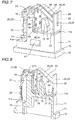
Fig. 6 is an exploded perspective view of the socket shown inFig. 1 ; -
Fig. 7 is a perspective view illustrating a state where a case cover is detached from the socket shown inFig. 1 ; -
Fig. 8 is a vertical sectional view of the socket shown inFig. 7 ; -
Fig. 9 is a left side view for explaining a method for using the socket shown inFig. 1 ; -
Fig. 10 is a vertical sectional view of the socket shown inFig. 9 ; -
Fig. 11 is a perspective view illustrating a second embodiment of a socket according to the present invention; -
Fig. 12 is a plan view of the socket shown inFig. 11 ; -
Fig. 13 is a partial front view of the socket shown inFig. 1 ; -
Fig. 14 is an exploded perspective view of the socket shown inFig. 1 ; -
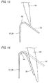
Fig. 15 is an explanatory view for explaining a method for analyzing an internal stress; -
Fig. 16 is an explanatory view for explaining a method for analyzing an internal stress; and -
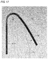
Fig. 17 is a stress distribution view illustrating an analysis result. - Embodiments of a socket according to the present invention will be described with reference to accompanying drawings of
Figs. 1 to 14 . - The socket according to a first embodiment is formed by a
base 10, a connection fitting 20 and acase cover 40 as shown in the accompanying drawings ofFigs. 1 to 10 . - As shown in
Fig. 6 , aseating 11 is protruded from an upper surface of thebase 10 to form anannular step 12. Aconnection hole 13 is provided in anupper surface 11 a which is one step lower in the upper surface of theseating 11. Further, asupport protrusion 14 is protruded at a rim of anupper surface 11 b which is one step higher in the upper surface of theseating 11. Furthermore, aposition restricting protrusion 15 is integrally molded with a nearly center of theupper surface 11 b. - The
position restricting protrusion 15 includes a position restrictingtapered surface 16 at an upper end of theposition restricting protrusion 15. Further,engagement claws seating 11 and on opposing outside surfaces. - In addition, in the embodiment, the
position restricting protrusion 15 is integrally molded with thebase 10, and the connection fitting 20 described below is assembled to thebase 10. Hence, precision to position the connection fitting 20 is high, and an assembly error is little. As a result, when an operation driver (not shown) pressespressure springs 35 of the connection fitting 20, a pressing position does not vary, so that it is possible to effectively prevent occurrence of plastic deformation. - Particularly, the position restricting
tapered surface 16 has an inclined angle which can come into planar contact with thepressure springs 35 when thepressure springs 35 of the connection fitting 20 described below elastically deform. Consequently, it is possible to effectively prevent plastic deformation of thepressure springs 35. - As shown in
Fig. 6 , the connection fitting 20 is formed by abracket 21 and a spring member 30 whose sectional shape is a nearly V shape. - A
retaining portion 22 is formed at one side of thebracket 21 provided with a through-hole 21 a by bending a conductive metal plate by way of press working, and acaulked portion 23, abottom portion 24 and a pressure contact portion 25 are formed at the other side. - The retaining
portion 22 has a shape which can retain leads which are not shown by way of caulking work. - Further, the
caulked portion 23 is formed by having a plurality ofcaulking projections 26 project from a surface of thecaulked portion 23, and asquare fitting hole 27 is formed in thebottom portion 24. Furthermore, a pair of pressurecontact receiving portions slit 28 formed at a free end of the pressure contact portion 25. - The spring member 30 is bent in a nearly V shape, and has pluralities of caulking
small holes 32 and caulkinglarge holes 33 at the caulkedportion 31 at one side of the spring member 30. Further, the spring member 30 has aslit 34 at a free end which elastically deforms at the other side of the spring member 30 to form a pair of pressure springs 35 and 35. Furthermore, by caulking and fixing the caulkingsmall holes 32 and the caulkinglarge holes 33 of the spring member 30 to thecaulking projections bracket 21, leading end portions of the pressure springs 35 and 35 of the spring member 30 come into pressure contact with the pressurecontact receiving portions bracket 21. - Hence, the
fitting hole 27 provided to thebottom portion 24 of thebracket 21 is fitted to and assembled to theposition restricting protrusion 15 of thebase 10. Further, leads which are not shown and are inserted from a lower side via theconnection hole 13 of the base 10 are caulked and fixed to and are electrically connected to the retainingportion 22 of thebracket 21. - As shown in
Fig. 4 , the case cover 40 has a box shape which can fit to theannular step 12 of thebase 10, and has a step shape including astep 41 at a single side of an upper surface of the box shape. Further, at a position corresponding to an upper end surface of thesupport protrusion 14 of the base 10 on an upper surface of thestep 41, a recessedportion 42 is formed. Furthermore, at a bottom surface of the recessedportion 42, a through-hole 43 (Fig. 5 ) continuing to the through-hole 21 a of thebracket 21 is formed. Hence, thebracket 21 can be electrically connected to thebracket 21 of another neighboring socket (not shown) via the through-hole 43 of thecase cover 40. - Further, at a position corresponding to an intermediate area of the pressure springs 35 on the upper surface except the
step 41, the case cover 40 has anoperation hole 44 in which the operation driver not shown can be inserted. Furthermore, at a position corresponding to free ends of the pressure springs 35, insertion holes 45 in which leads can be inserted are formed. At an opening rim of eachinsertion hole 45, a chamferedportion 45a which makes it easy to insert leads is formed. - Further, at a corner of the
step 41, aguide notch 46 having substantially a semi-arc surface is formed to guide the operation driver which is inserted in theoperation hole 44. - Furthermore, as shown in
Figs. 4 and 5 , the case cover 40 is integrally molded with aguide partition wall 47 to bridge theguide partition wall 47 between a ceiling surface and an inside surface of thecase cover 40. Theguide partition wall 47 may engage with theslit 28 provided to thebracket 21 and theslit 34 of the spring member 30. Further, theguide partition wall 47 includes at a lower end rim of the guide partition wall 47 a notch 48 (Fig. 5 ) which engages with theposition restricting protrusion 15 of thebase 10. - Furthermore, the case cover 40 includes engagement holes 49 (
Fig. 6 ) which engage with theengagement claws 17 of the base 10 in opposing side surfaces. - Still further, by fitting the case cover 40 to the
annular step 12 of thebase 10, the engagement holes 49 of the case cover 40 engage with and are integrally formed with theengagement claws 17 of the base 10 (Fig. 1 ). Thus, theguide partition wall 47 of the case cover 40 engages with theslit 28 of thebracket 21 and theslit 34 of the spring member 30 (Fig. 4 ). Further, thenotch 48 of theguide partition wall 47 engages with theposition restricting protrusion 15 of the base 10 to partition the pressure springs 35 and 35. - When the socket is connected with a lead, as shown in
Fig. 10 , anoperation driver 50 is inserted in theoperation hole 44 to press the intermediate area of the pressure springs 35 and push down the pressure springs 35. Subsequently, the lead inserted through theinsertion hole 45 is positioned between the leading end portions of the pressure springs 35 and the pressurecontact receiving portions 29. Then, when theoperation driver 50 is pulled, the pressure springs 35 are elastically restored, and the leading end portions of the pressure springs 35 and the pressurecontact receiving portions 29 sandwich the lead. - Further, when the lead is detached, the
operation driver 50 is inserted in theoperation hole 44 to press the intermediate area of the pressure springs 35 and push down the pressure springs 35, so that it is possible to detach the lead. - According to the embodiment, when the
operation driver 50 pushes down the pressure springs 35, the positions of the pressure springs 35 are restricted by the position restricting taperedsurface 16 of theposition restricting protrusion 15. Consequently, it is possible to prevent plastic deformation of the pressure springs 35. - A socket according to a second embodiment is substantially the same as that of the first embodiment as shown in
Figs. 11 to 14 , and differs from the first embodiment in that aguide notch 46 provided to astep 41 of acase cover 40 is formed by a pair of flat and triangular tapered surfaces. - The
guide notch 46 is formed by a pair of flat and triangular tapered surfaces. Consequently, by inserting an operation driver (not shown) along theguide notch 46, it is easy to position the operation driver. As a result, the operation driver can accurately and quickly operate the pressure springs 35. - Particularly when the operation driver is inserted along the
guide notch 46, spring forces of the pressure springs 35 work on the operation driver. Hence, a retaining state of the operation driver stabilizes. - Further, placing the operation driver in direct contact with a corner of the case cover 40 without providing the
guide notch 46 wears away the corner of thecase cover 40. However, by providing theguide notch 46, the operation driver comes into linear contact with theguide notch 46. Consequently, there is an advantage that the case cover 40 is hardly worn away. - The other components are the same as those of the first embodiment and therefore the same components will be assigned the same reference numerals and will not be described.
- A stress distribution was analyzed in case where, as shown in
Figs. 15 and 16 , an intermediate area of pressure springs 35 of a spring member 30 according to the above embodiments was pushed down by anoperation driver 50 and was elastically deformed.Fig. 17 illustrates an analysis result. - As is clear from
Fig. 17 , it was found that an internal stress concentrates at a flexingportion 36 of the spring member 30, and, more particularly, a side of a caulkedportion 31 of the flexingportion 36. - In addition, as shown in
Fig. 17 , in the above embodiments, a position restricting taperedsurface 16 is provided such that the pressure springs 35 of the spring member 30 come into contact with the position restricting taperedsurface 16 of aposition restricting protrusion 15 in an elastic deformation area. Consequently, it is possible to prevent plastic deformation of the pressure springs 35. - The socket according to the present invention is not limited to the above-described socket, and is applicable to a socket which can connect four leads.
Claims (6)
- A socket comprising:a base; anda connection fitting including a bracket and a spring member and assembled to an upper surface of the base,the spring member of the connection fitting being pressed and elastically deformed to sandwich a lead between the bracket and the spring member,whereina position restricting protrusion configured to come into contact with the pressed and deformed spring member and prevent plastic deformation is protruded on the upper surface of the base.
- The socket according to claim 1, wherein the position restricting protrusion is integrally molded with the base.
- The socket according to claim 1 or 2, wherein a position restricting tapered surface which the spring member comes into planar contact with is formed at an upper end of the position restricting protrusion.
- The socket according to any one of claims 1 to 3, wherein a fitting hole configured to fit to the position restricting protrusion protruded from the base is provided to the bracket of the connection fitting.
- The socket according to any one of claims 1 to 4, wherein
a guide partition wall is bridged between and integrally molded with a ceiling surface and an inside surface of a case cover of a box shape configured to fit to the base and to cover the connection fitting,
the guide partition wall engages with a slit provided to the bracket and the spring member of the connection fitting, and
an operation driver inserted along the guide partition wall through an operation hole provided on the ceiling surface of the case cover presses and elastically deforms a pressure spring of the spring member. - The socket according to claim 5, wherein a notch configured to engage with the position restricting protrusion provided to the base is formed at a lower end rim of the guide partition wall.
Applications Claiming Priority (1)
| Application Number | Priority Date | Filing Date | Title |
|---|---|---|---|
| JP2015182123A JP6531585B2 (en) | 2015-09-15 | 2015-09-15 | socket |
Publications (2)
| Publication Number | Publication Date |
|---|---|
| EP3145029A1 true EP3145029A1 (en) | 2017-03-22 |
| EP3145029B1 EP3145029B1 (en) | 2018-10-17 |
Family
ID=56893702
Family Applications (1)
| Application Number | Title | Priority Date | Filing Date |
|---|---|---|---|
| EP16185909.5A Active EP3145029B1 (en) | 2015-09-15 | 2016-08-26 | Socket |
Country Status (4)
| Country | Link |
|---|---|
| US (1) | US9799979B2 (en) |
| EP (1) | EP3145029B1 (en) |
| JP (1) | JP6531585B2 (en) |
| CN (1) | CN106532282B (en) |
Cited By (2)
| Publication number | Priority date | Publication date | Assignee | Title |
|---|---|---|---|---|
| EP3758151A1 (en) * | 2019-06-27 | 2020-12-30 | Phoenix Contact GmbH & Co. KG | Terminal arrangement for connecting at least one electrical conductor |
| WO2023156459A1 (en) * | 2022-02-16 | 2023-08-24 | Wago Verwaltungsgesellschaft Mbh | Conductor terminal |
Families Citing this family (5)
| Publication number | Priority date | Publication date | Assignee | Title |
|---|---|---|---|---|
| DE202015105023U1 (en) * | 2015-09-22 | 2016-12-23 | Weidmüller Interface GmbH & Co. KG | Connection device for conductors |
| DE102016111627A1 (en) * | 2016-06-24 | 2017-12-28 | Wago Verwaltungsgesellschaft Mbh | Conductor terminal |
| JP6597822B2 (en) * | 2018-03-23 | 2019-10-30 | 富士電機機器制御株式会社 | Electrical equipment connection structure |
| CN109361078B (en) * | 2018-10-10 | 2021-02-09 | 宁波公牛电器有限公司 | A wiring structure and switch socket |
| CN111193118B (en) * | 2018-11-15 | 2021-05-07 | 町洋企业股份有限公司 | Double-wiring connector |
Citations (5)
| Publication number | Priority date | Publication date | Assignee | Title |
|---|---|---|---|---|
| DE20210105U1 (en) * | 2002-06-29 | 2002-10-02 | Wago Verwaltungsgmbh | Electrical connection for terminals, connectors or devices |
| EP1429418A1 (en) * | 2002-12-13 | 2004-06-16 | Tyco Electronics Corporation | Electrical connector with integral wire release member |
| US20050042912A1 (en) * | 2003-09-06 | 2005-02-24 | Weidmueller Interface Gmbh & Co. Kg | Connector apparatus adapted for the direct plug-in connection of conductors |
| DE102009004513A1 (en) | 2009-01-09 | 2010-07-22 | Phoenix Contact Gmbh & Co. Kg | Clamping spring for a spring-loaded terminal |
| US20140065892A1 (en) * | 2012-09-05 | 2014-03-06 | Schneider Electric Industries Sas | Electrical connector and a connector assembly |
Family Cites Families (3)
| Publication number | Priority date | Publication date | Assignee | Title |
|---|---|---|---|---|
| JPS51130088U (en) * | 1975-04-10 | 1976-10-20 | ||
| TWI351799B (en) * | 2006-04-25 | 2011-11-01 | Wago Verwaltungs Gmbh | Elektr. verbinder |
| DE202008014469U1 (en) * | 2008-10-31 | 2010-03-18 | Weidmüller Interface GmbH & Co. KG | Terminal for connecting conductor ends |
-
2015
- 2015-09-15 JP JP2015182123A patent/JP6531585B2/en not_active Expired - Fee Related
-
2016
- 2016-08-11 CN CN201610656886.4A patent/CN106532282B/en active Active
- 2016-08-26 US US15/248,492 patent/US9799979B2/en active Active
- 2016-08-26 EP EP16185909.5A patent/EP3145029B1/en active Active
Patent Citations (5)
| Publication number | Priority date | Publication date | Assignee | Title |
|---|---|---|---|---|
| DE20210105U1 (en) * | 2002-06-29 | 2002-10-02 | Wago Verwaltungsgmbh | Electrical connection for terminals, connectors or devices |
| EP1429418A1 (en) * | 2002-12-13 | 2004-06-16 | Tyco Electronics Corporation | Electrical connector with integral wire release member |
| US20050042912A1 (en) * | 2003-09-06 | 2005-02-24 | Weidmueller Interface Gmbh & Co. Kg | Connector apparatus adapted for the direct plug-in connection of conductors |
| DE102009004513A1 (en) | 2009-01-09 | 2010-07-22 | Phoenix Contact Gmbh & Co. Kg | Clamping spring for a spring-loaded terminal |
| US20140065892A1 (en) * | 2012-09-05 | 2014-03-06 | Schneider Electric Industries Sas | Electrical connector and a connector assembly |
Cited By (2)
| Publication number | Priority date | Publication date | Assignee | Title |
|---|---|---|---|---|
| EP3758151A1 (en) * | 2019-06-27 | 2020-12-30 | Phoenix Contact GmbH & Co. KG | Terminal arrangement for connecting at least one electrical conductor |
| WO2023156459A1 (en) * | 2022-02-16 | 2023-08-24 | Wago Verwaltungsgesellschaft Mbh | Conductor terminal |
Also Published As
| Publication number | Publication date |
|---|---|
| EP3145029B1 (en) | 2018-10-17 |
| CN106532282A (en) | 2017-03-22 |
| US20170093073A1 (en) | 2017-03-30 |
| JP2017059362A (en) | 2017-03-23 |
| CN106532282B (en) | 2019-06-18 |
| US9799979B2 (en) | 2017-10-24 |
| JP6531585B2 (en) | 2019-06-19 |
Similar Documents
| Publication | Publication Date | Title |
|---|---|---|
| US9774107B2 (en) | Socket having a connection fitting with a divided spring member | |
| EP3145029B1 (en) | Socket | |
| US9484656B2 (en) | Electrical connector | |
| CN111092327B (en) | Movable connector | |
| US8105114B2 (en) | Intermediate electrical connector | |
| KR20190118953A (en) | Connector | |
| KR20160026662A (en) | Connector | |
| EP3790116B1 (en) | Connector and connector manufacturing method | |
| CN109638579B (en) | Connector | |
| EP2805385A1 (en) | Connector | |
| KR20100011831A (en) | Connector having front-holder | |
| US9219334B2 (en) | Connection terminal and connector provided therewith | |
| US12082361B2 (en) | Electronic device | |
| US8309865B2 (en) | Resin-molded article fit with a metal plate | |
| KR101611781B1 (en) | Connection terminal and connector using same | |
| EP2750253A1 (en) | Connector | |
| JP2008084878A (en) | Manufacturing method of electrical connector having fixing metal fitting | |
| KR20140114575A (en) | Female Terminal | |
| CN108780987B (en) | support part | |
| KR20220030634A (en) | Connector having terminal positioning assurance member and connector assembly having this | |
| JP2008130409A (en) | Electrical connector assembly | |
| JP6386796B2 (en) | connector |
Legal Events
| Date | Code | Title | Description |
|---|---|---|---|
| PUAI | Public reference made under article 153(3) epc to a published international application that has entered the european phase |
Free format text: ORIGINAL CODE: 0009012 |
|
| STAA | Information on the status of an ep patent application or granted ep patent |
Free format text: STATUS: REQUEST FOR EXAMINATION WAS MADE |
|
| 17P | Request for examination filed |
Effective date: 20170209 |
|
| AK | Designated contracting states |
Kind code of ref document: A1 Designated state(s): AL AT BE BG CH CY CZ DE DK EE ES FI FR GB GR HR HU IE IS IT LI LT LU LV MC MK MT NL NO PL PT RO RS SE SI SK SM TR |
|
| AX | Request for extension of the european patent |
Extension state: BA ME |
|
| STAA | Information on the status of an ep patent application or granted ep patent |
Free format text: STATUS: EXAMINATION IS IN PROGRESS |
|
| 17Q | First examination report despatched |
Effective date: 20170706 |
|
| GRAP | Despatch of communication of intention to grant a patent |
Free format text: ORIGINAL CODE: EPIDOSNIGR1 |
|
| STAA | Information on the status of an ep patent application or granted ep patent |
Free format text: STATUS: GRANT OF PATENT IS INTENDED |
|
| RIC1 | Information provided on ipc code assigned before grant |
Ipc: H01R 13/502 20060101ALN20180515BHEP Ipc: H01R 13/506 20060101ALN20180515BHEP Ipc: H01R 4/48 20060101AFI20180515BHEP Ipc: H01R 9/24 20060101ALN20180515BHEP |
|
| INTG | Intention to grant announced |
Effective date: 20180601 |
|
| GRAS | Grant fee paid |
Free format text: ORIGINAL CODE: EPIDOSNIGR3 |
|
| GRAA | (expected) grant |
Free format text: ORIGINAL CODE: 0009210 |
|
| STAA | Information on the status of an ep patent application or granted ep patent |
Free format text: STATUS: THE PATENT HAS BEEN GRANTED |
|
| AK | Designated contracting states |
Kind code of ref document: B1 Designated state(s): AL AT BE BG CH CY CZ DE DK EE ES FI FR GB GR HR HU IE IS IT LI LT LU LV MC MK MT NL NO PL PT RO RS SE SI SK SM TR |
|
| REG | Reference to a national code |
Ref country code: GB Ref legal event code: FG4D |
|
| REG | Reference to a national code |
Ref country code: CH Ref legal event code: EP |
|
| REG | Reference to a national code |
Ref country code: IE Ref legal event code: FG4D |
|
| REG | Reference to a national code |
Ref country code: DE Ref legal event code: R096 Ref document number: 602016006486 Country of ref document: DE Ref country code: AT Ref legal event code: REF Ref document number: 1055083 Country of ref document: AT Kind code of ref document: T Effective date: 20181115 |
|
| REG | Reference to a national code |
Ref country code: NL Ref legal event code: MP Effective date: 20181017 |
|
| REG | Reference to a national code |
Ref country code: LT Ref legal event code: MG4D |
|
| REG | Reference to a national code |
Ref country code: AT Ref legal event code: MK05 Ref document number: 1055083 Country of ref document: AT Kind code of ref document: T Effective date: 20181017 |
|
| PG25 | Lapsed in a contracting state [announced via postgrant information from national office to epo] |
Ref country code: NL Free format text: LAPSE BECAUSE OF FAILURE TO SUBMIT A TRANSLATION OF THE DESCRIPTION OR TO PAY THE FEE WITHIN THE PRESCRIBED TIME-LIMIT Effective date: 20181017 |
|
| PG25 | Lapsed in a contracting state [announced via postgrant information from national office to epo] |
Ref country code: NO Free format text: LAPSE BECAUSE OF FAILURE TO SUBMIT A TRANSLATION OF THE DESCRIPTION OR TO PAY THE FEE WITHIN THE PRESCRIBED TIME-LIMIT Effective date: 20190117 Ref country code: HR Free format text: LAPSE BECAUSE OF FAILURE TO SUBMIT A TRANSLATION OF THE DESCRIPTION OR TO PAY THE FEE WITHIN THE PRESCRIBED TIME-LIMIT Effective date: 20181017 Ref country code: LT Free format text: LAPSE BECAUSE OF FAILURE TO SUBMIT A TRANSLATION OF THE DESCRIPTION OR TO PAY THE FEE WITHIN THE PRESCRIBED TIME-LIMIT Effective date: 20181017 Ref country code: IS Free format text: LAPSE BECAUSE OF FAILURE TO SUBMIT A TRANSLATION OF THE DESCRIPTION OR TO PAY THE FEE WITHIN THE PRESCRIBED TIME-LIMIT Effective date: 20190217 Ref country code: FI Free format text: LAPSE BECAUSE OF FAILURE TO SUBMIT A TRANSLATION OF THE DESCRIPTION OR TO PAY THE FEE WITHIN THE PRESCRIBED TIME-LIMIT Effective date: 20181017 Ref country code: AT Free format text: LAPSE BECAUSE OF FAILURE TO SUBMIT A TRANSLATION OF THE DESCRIPTION OR TO PAY THE FEE WITHIN THE PRESCRIBED TIME-LIMIT Effective date: 20181017 Ref country code: LV Free format text: LAPSE BECAUSE OF FAILURE TO SUBMIT A TRANSLATION OF THE DESCRIPTION OR TO PAY THE FEE WITHIN THE PRESCRIBED TIME-LIMIT Effective date: 20181017 Ref country code: ES Free format text: LAPSE BECAUSE OF FAILURE TO SUBMIT A TRANSLATION OF THE DESCRIPTION OR TO PAY THE FEE WITHIN THE PRESCRIBED TIME-LIMIT Effective date: 20181017 Ref country code: BG Free format text: LAPSE BECAUSE OF FAILURE TO SUBMIT A TRANSLATION OF THE DESCRIPTION OR TO PAY THE FEE WITHIN THE PRESCRIBED TIME-LIMIT Effective date: 20190117 Ref country code: PL Free format text: LAPSE BECAUSE OF FAILURE TO SUBMIT A TRANSLATION OF THE DESCRIPTION OR TO PAY THE FEE WITHIN THE PRESCRIBED TIME-LIMIT Effective date: 20181017 |
|
| PG25 | Lapsed in a contracting state [announced via postgrant information from national office to epo] |
Ref country code: PT Free format text: LAPSE BECAUSE OF FAILURE TO SUBMIT A TRANSLATION OF THE DESCRIPTION OR TO PAY THE FEE WITHIN THE PRESCRIBED TIME-LIMIT Effective date: 20190217 Ref country code: AL Free format text: LAPSE BECAUSE OF FAILURE TO SUBMIT A TRANSLATION OF THE DESCRIPTION OR TO PAY THE FEE WITHIN THE PRESCRIBED TIME-LIMIT Effective date: 20181017 Ref country code: SE Free format text: LAPSE BECAUSE OF FAILURE TO SUBMIT A TRANSLATION OF THE DESCRIPTION OR TO PAY THE FEE WITHIN THE PRESCRIBED TIME-LIMIT Effective date: 20181017 Ref country code: GR Free format text: LAPSE BECAUSE OF FAILURE TO SUBMIT A TRANSLATION OF THE DESCRIPTION OR TO PAY THE FEE WITHIN THE PRESCRIBED TIME-LIMIT Effective date: 20190118 Ref country code: RS Free format text: LAPSE BECAUSE OF FAILURE TO SUBMIT A TRANSLATION OF THE DESCRIPTION OR TO PAY THE FEE WITHIN THE PRESCRIBED TIME-LIMIT Effective date: 20181017 |
|
| REG | Reference to a national code |
Ref country code: DE Ref legal event code: R097 Ref document number: 602016006486 Country of ref document: DE |
|
| PG25 | Lapsed in a contracting state [announced via postgrant information from national office to epo] |
Ref country code: CZ Free format text: LAPSE BECAUSE OF FAILURE TO SUBMIT A TRANSLATION OF THE DESCRIPTION OR TO PAY THE FEE WITHIN THE PRESCRIBED TIME-LIMIT Effective date: 20181017 Ref country code: IT Free format text: LAPSE BECAUSE OF FAILURE TO SUBMIT A TRANSLATION OF THE DESCRIPTION OR TO PAY THE FEE WITHIN THE PRESCRIBED TIME-LIMIT Effective date: 20181017 Ref country code: DK Free format text: LAPSE BECAUSE OF FAILURE TO SUBMIT A TRANSLATION OF THE DESCRIPTION OR TO PAY THE FEE WITHIN THE PRESCRIBED TIME-LIMIT Effective date: 20181017 |
|
| PLBE | No opposition filed within time limit |
Free format text: ORIGINAL CODE: 0009261 |
|
| STAA | Information on the status of an ep patent application or granted ep patent |
Free format text: STATUS: NO OPPOSITION FILED WITHIN TIME LIMIT |
|
| PG25 | Lapsed in a contracting state [announced via postgrant information from national office to epo] |
Ref country code: EE Free format text: LAPSE BECAUSE OF FAILURE TO SUBMIT A TRANSLATION OF THE DESCRIPTION OR TO PAY THE FEE WITHIN THE PRESCRIBED TIME-LIMIT Effective date: 20181017 Ref country code: SM Free format text: LAPSE BECAUSE OF FAILURE TO SUBMIT A TRANSLATION OF THE DESCRIPTION OR TO PAY THE FEE WITHIN THE PRESCRIBED TIME-LIMIT Effective date: 20181017 Ref country code: SK Free format text: LAPSE BECAUSE OF FAILURE TO SUBMIT A TRANSLATION OF THE DESCRIPTION OR TO PAY THE FEE WITHIN THE PRESCRIBED TIME-LIMIT Effective date: 20181017 Ref country code: RO Free format text: LAPSE BECAUSE OF FAILURE TO SUBMIT A TRANSLATION OF THE DESCRIPTION OR TO PAY THE FEE WITHIN THE PRESCRIBED TIME-LIMIT Effective date: 20181017 |
|
| 26N | No opposition filed |
Effective date: 20190718 |
|
| PG25 | Lapsed in a contracting state [announced via postgrant information from national office to epo] |
Ref country code: SI Free format text: LAPSE BECAUSE OF FAILURE TO SUBMIT A TRANSLATION OF THE DESCRIPTION OR TO PAY THE FEE WITHIN THE PRESCRIBED TIME-LIMIT Effective date: 20181017 |
|
| PG25 | Lapsed in a contracting state [announced via postgrant information from national office to epo] |
Ref country code: TR Free format text: LAPSE BECAUSE OF FAILURE TO SUBMIT A TRANSLATION OF THE DESCRIPTION OR TO PAY THE FEE WITHIN THE PRESCRIBED TIME-LIMIT Effective date: 20181017 |
|
| PG25 | Lapsed in a contracting state [announced via postgrant information from national office to epo] |
Ref country code: LU Free format text: LAPSE BECAUSE OF NON-PAYMENT OF DUE FEES Effective date: 20190826 Ref country code: CH Free format text: LAPSE BECAUSE OF NON-PAYMENT OF DUE FEES Effective date: 20190831 Ref country code: LI Free format text: LAPSE BECAUSE OF NON-PAYMENT OF DUE FEES Effective date: 20190831 Ref country code: MC Free format text: LAPSE BECAUSE OF FAILURE TO SUBMIT A TRANSLATION OF THE DESCRIPTION OR TO PAY THE FEE WITHIN THE PRESCRIBED TIME-LIMIT Effective date: 20181017 |
|
| REG | Reference to a national code |
Ref country code: BE Ref legal event code: MM Effective date: 20190831 |
|
| PG25 | Lapsed in a contracting state [announced via postgrant information from national office to epo] |
Ref country code: FR Free format text: LAPSE BECAUSE OF NON-PAYMENT OF DUE FEES Effective date: 20190831 Ref country code: IE Free format text: LAPSE BECAUSE OF NON-PAYMENT OF DUE FEES Effective date: 20190826 |
|
| PG25 | Lapsed in a contracting state [announced via postgrant information from national office to epo] |
Ref country code: BE Free format text: LAPSE BECAUSE OF NON-PAYMENT OF DUE FEES Effective date: 20190831 |
|
| GBPC | Gb: european patent ceased through non-payment of renewal fee |
Effective date: 20200826 |
|
| PG25 | Lapsed in a contracting state [announced via postgrant information from national office to epo] |
Ref country code: CY Free format text: LAPSE BECAUSE OF FAILURE TO SUBMIT A TRANSLATION OF THE DESCRIPTION OR TO PAY THE FEE WITHIN THE PRESCRIBED TIME-LIMIT Effective date: 20181017 |
|
| PG25 | Lapsed in a contracting state [announced via postgrant information from national office to epo] |
Ref country code: MT Free format text: LAPSE BECAUSE OF FAILURE TO SUBMIT A TRANSLATION OF THE DESCRIPTION OR TO PAY THE FEE WITHIN THE PRESCRIBED TIME-LIMIT Effective date: 20181017 Ref country code: HU Free format text: LAPSE BECAUSE OF FAILURE TO SUBMIT A TRANSLATION OF THE DESCRIPTION OR TO PAY THE FEE WITHIN THE PRESCRIBED TIME-LIMIT; INVALID AB INITIO Effective date: 20160826 |
|
| PG25 | Lapsed in a contracting state [announced via postgrant information from national office to epo] |
Ref country code: GB Free format text: LAPSE BECAUSE OF NON-PAYMENT OF DUE FEES Effective date: 20200826 |
|
| PG25 | Lapsed in a contracting state [announced via postgrant information from national office to epo] |
Ref country code: MK Free format text: LAPSE BECAUSE OF FAILURE TO SUBMIT A TRANSLATION OF THE DESCRIPTION OR TO PAY THE FEE WITHIN THE PRESCRIBED TIME-LIMIT Effective date: 20181017 |
|
| PGFP | Annual fee paid to national office [announced via postgrant information from national office to epo] |
Ref country code: DE Payment date: 20250819 Year of fee payment: 10 |