EP3144943A1 - Pendulum-type electromagnetic actuator - Google Patents
Pendulum-type electromagnetic actuator Download PDFInfo
- Publication number
- EP3144943A1 EP3144943A1 EP16188928.2A EP16188928A EP3144943A1 EP 3144943 A1 EP3144943 A1 EP 3144943A1 EP 16188928 A EP16188928 A EP 16188928A EP 3144943 A1 EP3144943 A1 EP 3144943A1
- Authority
- EP
- European Patent Office
- Prior art keywords
- actuator
- moving
- core
- moving member
- stationary
- Prior art date
- Legal status (The legal status is an assumption and is not a legal conclusion. Google has not performed a legal analysis and makes no representation as to the accuracy of the status listed.)
- Granted
Links
Images




Classifications
-
- H—ELECTRICITY
- H01—ELECTRIC ELEMENTS
- H01F—MAGNETS; INDUCTANCES; TRANSFORMERS; SELECTION OF MATERIALS FOR THEIR MAGNETIC PROPERTIES
- H01F7/00—Magnets
- H01F7/06—Electromagnets; Actuators including electromagnets
- H01F7/08—Electromagnets; Actuators including electromagnets with armatures
- H01F7/14—Pivoting armatures
-
- F—MECHANICAL ENGINEERING; LIGHTING; HEATING; WEAPONS; BLASTING
- F03—MACHINES OR ENGINES FOR LIQUIDS; WIND, SPRING, OR WEIGHT MOTORS; PRODUCING MECHANICAL POWER OR A REACTIVE PROPULSIVE THRUST, NOT OTHERWISE PROVIDED FOR
- F03G—SPRING, WEIGHT, INERTIA OR LIKE MOTORS; MECHANICAL-POWER PRODUCING DEVICES OR MECHANISMS, NOT OTHERWISE PROVIDED FOR OR USING ENERGY SOURCES NOT OTHERWISE PROVIDED FOR
- F03G3/00—Other motors, e.g. gravity or inertia motors
- F03G3/06—Other motors, e.g. gravity or inertia motors using pendulums
-
- F—MECHANICAL ENGINEERING; LIGHTING; HEATING; WEAPONS; BLASTING
- F15—FLUID-PRESSURE ACTUATORS; HYDRAULICS OR PNEUMATICS IN GENERAL
- F15B—SYSTEMS ACTING BY MEANS OF FLUIDS IN GENERAL; FLUID-PRESSURE ACTUATORS, e.g. SERVOMOTORS; DETAILS OF FLUID-PRESSURE SYSTEMS, NOT OTHERWISE PROVIDED FOR
- F15B13/00—Details of servomotor systems ; Valves for servomotor systems
- F15B13/02—Fluid distribution or supply devices characterised by their adaptation to the control of servomotors
- F15B13/04—Fluid distribution or supply devices characterised by their adaptation to the control of servomotors for use with a single servomotor
- F15B13/042—Fluid distribution or supply devices characterised by their adaptation to the control of servomotors for use with a single servomotor operated by fluid pressure
- F15B13/043—Fluid distribution or supply devices characterised by their adaptation to the control of servomotors for use with a single servomotor operated by fluid pressure with electrically-controlled pilot valves
- F15B13/0438—Fluid distribution or supply devices characterised by their adaptation to the control of servomotors for use with a single servomotor operated by fluid pressure with electrically-controlled pilot valves the pilot valves being of the nozzle-flapper type
-
- F—MECHANICAL ENGINEERING; LIGHTING; HEATING; WEAPONS; BLASTING
- F15—FLUID-PRESSURE ACTUATORS; HYDRAULICS OR PNEUMATICS IN GENERAL
- F15B—SYSTEMS ACTING BY MEANS OF FLUIDS IN GENERAL; FLUID-PRESSURE ACTUATORS, e.g. SERVOMOTORS; DETAILS OF FLUID-PRESSURE SYSTEMS, NOT OTHERWISE PROVIDED FOR
- F15B9/00—Servomotors with follow-up action, e.g. obtained by feed-back control, i.e. in which the position of the actuated member conforms with that of the controlling member
- F15B9/02—Servomotors with follow-up action, e.g. obtained by feed-back control, i.e. in which the position of the actuated member conforms with that of the controlling member with servomotors of the reciprocatable or oscillatable type
- F15B9/06—Servomotors with follow-up action, e.g. obtained by feed-back control, i.e. in which the position of the actuated member conforms with that of the controlling member with servomotors of the reciprocatable or oscillatable type controlled by means using a fluid jet
- F15B9/07—Servomotors with follow-up action, e.g. obtained by feed-back control, i.e. in which the position of the actuated member conforms with that of the controlling member with servomotors of the reciprocatable or oscillatable type controlled by means using a fluid jet with electrical control means
-
- H—ELECTRICITY
- H01—ELECTRIC ELEMENTS
- H01F—MAGNETS; INDUCTANCES; TRANSFORMERS; SELECTION OF MATERIALS FOR THEIR MAGNETIC PROPERTIES
- H01F7/00—Magnets
- H01F7/06—Electromagnets; Actuators including electromagnets
- H01F7/08—Electromagnets; Actuators including electromagnets with armatures
- H01F7/121—Guiding or setting position of armatures, e.g. retaining armatures in their end position
- H01F7/122—Guiding or setting position of armatures, e.g. retaining armatures in their end position by permanent magnets
-
- H—ELECTRICITY
- H02—GENERATION; CONVERSION OR DISTRIBUTION OF ELECTRIC POWER
- H02K—DYNAMO-ELECTRIC MACHINES
- H02K33/00—Motors with reciprocating, oscillating or vibrating magnet, armature or coil system
- H02K33/16—Motors with reciprocating, oscillating or vibrating magnet, armature or coil system with polarised armatures moving in alternate directions by reversal or energisation of a single coil system
-
- H—ELECTRICITY
- H02—GENERATION; CONVERSION OR DISTRIBUTION OF ELECTRIC POWER
- H02K—DYNAMO-ELECTRIC MACHINES
- H02K41/00—Propulsion systems in which a rigid body is moved along a path due to dynamo-electric interaction between the body and a magnetic field travelling along the path
- H02K41/02—Linear motors; Sectional motors
- H02K41/035—DC motors; Unipolar motors
- H02K41/0352—Unipolar motors
- H02K41/0354—Lorentz force motors, e.g. voice coil motors
- H02K41/0358—Lorentz force motors, e.g. voice coil motors moving along a curvilinear path
-
- H—ELECTRICITY
- H01—ELECTRIC ELEMENTS
- H01F—MAGNETS; INDUCTANCES; TRANSFORMERS; SELECTION OF MATERIALS FOR THEIR MAGNETIC PROPERTIES
- H01F7/00—Magnets
- H01F7/06—Electromagnets; Actuators including electromagnets
- H01F7/08—Electromagnets; Actuators including electromagnets with armatures
- H01F7/081—Magnetic constructions
- H01F2007/086—Structural details of the armature
Definitions
- the subject matter disclosed herein generally relates to electromagnetic actuators.
- An electromagnetic actuator may be configured as a short-stroke electromechanical energy conversion device which converts electrical energy directly into mechanical energy. Such mechanical energy may include linear or rotational motion.
- An electromagnetic actuator may include moving parts that include permanent magnets (PMs) and/or a ferromagnetic member.
- Short-stroke electromagnetic actuators may be used to provide and/or generate oscillatory motion. Such short-stroke actuators have found multiple applications as short stroke linear motors, compressors, pumps, valves, etc. In aerospace applications, electromagnetic actuators with oscillatory motion can be used for valves, e.g., for fuel control, pumps, refrigeration systems, etc.
- a pendulum-type electromagnetic actuator includes a curved stationary member comprising a stationary core and a winding wound about the stationary core.
- a first moving member includes a first moving core and a first plurality of permanent magnets attached to the first moving core, the first moving member is curved and positioned on a first side of the stationary member.
- a second moving member includes a second moving core and a second plurality of permanent magnets attached to the second moving core, the second moving member is curved and position on a second side of the stationary member, the second side opposite the first side.
- the actuator further includes a pivot and a pivot connector connecting at least one of the first moving member and the second moving member to the pivot such that the curved moving member rotates about the pivot.
- inventions of the present disclosure include an improved electromagnetic actuator that is a pendulum-type actuator. Further technical effects include electromagnetic actuators that may provide high force/torque density and have low power losses along with convection cooling and not clogging.
- a type of arc-shaped, short-stroke, pendulum-type actuator is presented.
- the pendulum-type actuator in accordance with some embodiments disclosed herein may find broad applications in aerospace technology, e.g., servo control valves (e.g., flapper nozzle servo valves, jet pipe servo valves, etc.) used in aircraft systems, including for example fuel, oil, hydraulic, pneumatic, and motor systems.
- servo control valves e.g., flapper nozzle servo valves, jet pipe servo valves, etc.
- actuators as described herein may be employed in various technology areas and/or applications outside of aircraft systems.
- FIG. 1 is a schematic illustration of a pendulum-type electromagnetic actuator as applied to a flapper nozzle servo valve. Although described herein with respect to a flapper nozzle servo valve, those of skill in the art will appreciate that embodiments of the pendulum-type electromagnetic actuator as described herein may be employed in various configurations and/or within various mechanism and devices, without departing from the scope of the disclosure. Thus, FIG. 1 and the description thereof are presented merely for illustrative purposes.
- the flapper nozzle servo valve 100 includes a flapper stage 102, a servo stage 104, and an actuator stage 106.
- the flapper stage 102 may include an actuator 108, a flapper 110, and one or more nozzles 112.
- the flapper 110 may be operably connected to a movable portion of the actuator 108. In operation, current may be applied to the actuator 108 causing the moveable portion thereof to move or oscillate. As the movable portion of the actuator 108 moves, the flapper 110 moves therewith. Movement of the flapper 110 may cause the pressure at the nozzles 112 to change, thus causing part of the servo stage 104 to operate.
- the servo state 104 may include a servo (e.g., spool valve) 114.
- the servo 114 may be configured to move linearly, e.g., left and right in FIG. 1 , based on pressure differentials on either end and/or within portions of the servo 114.
- the servo 114 may be biased as will be appreciated by those of skill in the art. Movement of the servo 114 may cause the actuator stage 106 to operate.
- the servo 114 depending on the position and/or movement thereof, may cause a pressure differential about a piston 116 in the actuator stage 106 to move, e.g., linearly.
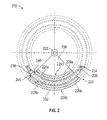
- a pendulum-type actuator 220 includes a pivot 222 around which components of the pendulum-type actuator 220 may rotate.
- Connected to the pivot 222 may be one or more moving members 224, e.g., first moving member 224a and second moving member 224b (collectively moving member 224).
- the moving members 224a, 224b may each include a moving cores 226a, 226b and permanent magnets 228a, 228b, respectively.
- the moving members 224a, 224b may form a hollow, cylindrical structure that is operationally connected to the pivot 222 by a pivot connector 230.
- the permanent magnets 228a, 228b may be positioned on an interior side of the cylinder of the moving members 224a, 224b and the moving core 226a, 226b may form an exterior of the cylinder of the respective moving members 224a, 224b.
- the pivot connector 230 may be configured as a solid connector, rigid arms, a single connector sheet, or take any other shape or configuration that connects the moving members 224a, 224b to the pivot 222.
- the moving members 224a, 224b may be formed from two separate elements each having permanent magnets 228a, 228b attached to a respective moving core 226a, 226b.
- the two moving members 224a, 224b may then be connected by a connector such as a bracket, a brace, or other connecting mechanism (e.g., see FIG. 3B ).
- An exterior surface 232 of the second moving member 224b may be configured having a support surface and/or attachment surface or mechanism such that a flapper, e.g., as shown in FIG. 1 , may be connected thereto.
- the exterior surface 232 of the second moving member 224b may be configured to operationally connect to another device to provide movement, oscillation, and/or actuation to the other device, e.g., a flapper of a flapper nozzle servo valve.
- the stationary member 234 may include a winding 236, such as an armature winding, wound around a stationary core 238.
- the stationary core 238 may be configured as an armature ferromagnetic core, and in other non-limiting embodiments the stationary core may be configured as a support structure, ferromagnetic or non-ferromagnetic.
- an arc-shaped stationary member 232 is placed between two arc-shaped rows moving members 224a, 224b. Air gaps 240 are formed between the permanent magnets 228a, 228b of the moving members 224a, 224b and the winding 236 of the stationary member 232.
- the permanent magnets 228a, 228b together with moving cores 226a, 226b constitute mechanically one part that can move around or rotate about the pivot 222 within an angle of 360° or less.
- the angle of rotation of the moving members 224a, 224b about the pivot 222 may be less than 180°, and in some embodiments may be defined by the circumferential extent, or length, of the stationary member 234. For example, if the stationary member 234 extends 360°, then the moving member 224 may move a full 360° about the pivot 222, and when the stationary part 232 extends for less than 360°, the moving part 224 may pivot only for the same angular extent. If the actuator is configured to rotate a full 360°, the actuator may be employed as a motor.
- the stationary core 238 may be made of ferromagnetic or non-ferromagnetic materials.
- actuators such as shown in FIG. 2
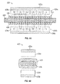
- FIG. 3A is a top-down cut-away view of a portion of an actuator 320 and FIG. 3B is an end-on view of the portion of actuator 320 shown in FIG. 3A .
- FIG. 3B is an end-on view of the portion of actuator 320 shown in FIG. 3A .
- the actuator 320 may be curved such as that shown in FIG. 2 .
- a moving member 324 may be formed from two separate moving members 324a, 324b, each moving member 324a, 324b having a respective moving core 326a, 326b and permanent magnets 328a, 328b.
- the two moving members 324a, 324b may be attached or connected by a connector 342.
- the connector 342 may take any number of configurations.
- two connectors 342 attached on either side of the moving members 324a, 324b may be employed without departing from the scope of the present disclosure.
- the permanent magnets 328a, 328b may be configured having alternating patterns.
- a first moving member 324a have a N-S-N-S pattern and a second moving member 324b may have an opposite alternating pattern of S-N-S-N.
- the stationary member 334 may be formed of a winding 336 wrapped about a curved stationary core 338.
- the stationary core 338 may be a non-ferromagnetic armature core with the winding 336 formed of rectangular or square-shaped conductors.
- the resulting magnetic flux is indicated by the dashed lines in FIG. 3A . As shown, the magnetic flux extends from the first moving member 324a, penetrates through the stationary member 334, and passes through the permanent magnets 328b of the second moving member 324b.
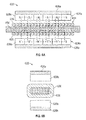
- FIG. 4A is a top-down cut-away view of a portion of an actuator 420 and FIG. 4B is an end-on view of the portion of the actuator 420 shown in FIG. 4A .
- a moving member 424 e.g., similar to moving member 224 of FIG. 2
- the permanent magnets 428a, 428b may have a similar configuration as that shown in FIG. 3A .
- the stationary member 434 may be formed of a winding 436 wrapped about a curved stationary core 438.
- the stationary core 438 may be a non-ferromagnetic armature core with the winding 436 formed of circular or round-shaped conductors.
- the resulting magnetic flux is indicated by the dashed lines in FIG. 4A . As shown, the magnetic flux extends from the first moving member 424a, penetrates through the stationary member 434, and passes through the opposing permanent magnets 428b of the second moving member 424b.
- FIG. 5A is a top-down cut-away view of a portion of an actuator 520 and FIG. 5B is an end-on view of the portion of actuator 520 shown in FIG. 5A .
- a moving member 524 e.g., similar to moving member 224 of FIG. 2
- the permanent magnets 528a, 528b may have a similar configuration as that shown in FIG. 3A .
- the stationary member 534 may be formed of a winding 536 wrapped about a curved stationary core 538.
- the stationary core 538 may be a ferromagnetic armature core with the winding 536 formed of rectangular or square-shaped conductors.
- the resulting magnetic flux is indicated by the dashed lines in FIG. 5A . As shown, the magnetic flux does not extend from the first moving member 524a to the second moving member 524b, but rather each moving member 524a, 524b forms a separate magnetic flux that does not penetrate through stationary member 534.
- FIGS. 6A and 6B another example configuration of permanent magnets about a ferromagnetic core in accordance with an embodiment is shown.
- FIG. 6A is a top-down cut-away view of a portion of an actuator 620 and FIG. 6B is an end-on view of the portion of actuator 620 shown in FIG. 6A .
- a moving member 624 e.g., similar to moving member 224 of FIG. 2 , may be formed from two separate moving members 624a, 624b, each moving member 624a, 624b having a respective moving core 626a, 626b and permanent magnets 628a, 628b.
- the permanent magnets 628a, 628b may have a similar configuration as that shown in FIG. 3A .
- the stationary member 634 may be formed of a winding 636 wrapped about a curved stationary core 638.
- the stationary core 638 may be a ferromagnetic armature core with the winding 636 formed of circular or round-shaped conductors.
- the resulting magnetic flux is indicated by the dashed lines in FIG. 6A . As shown, the magnetic flux does not extend from the first moving member 624a to the second moving member 624b, but rather each moving member 624 forms a separate magnetic flux that does not penetrate through stationary member 634.
- FIGS. 7A and 7B another example configuration of permanent magnets about a non-ferromagnetic core in accordance with an embodiment is shown.
- FIG. 7A is a top-down cut-away view of a portion of an actuator 720 and
- FIG. 7B is an end-on view of the portion of actuator 720 shown in FIG. 7A .
- a moving member 724 e.g., similar to moving member 224 of FIG. 2 , may be formed from two separate moving members 724a, 724b, each moving member 724a, 724b having a respective moving core 726a, 726b and permanent magnets 728a, 728b.
- the permanent magnets 728a, 728b may be configured as a Halbach array of permanent magnets.
- the arrows indicate the magnetization vector of individual permanent magnets of the Halbach array, with the vectors rotating along the length of the respective moving member 724a, 724b. As shown, the vector rotates from tangential to radial through a 360° pattern which is indicated by the arrows labeled on the permanent magnet elements 728a, 728b.
- the stationary member 734 may be formed of a winding 736 wrapped about a curved stationary core 738.
- the stationary core 738 may be a non-ferromagnetic armature core with the winding 736 formed of rectangular or square-shaped conductors.
- the resulting magnetic flux is indicated by the dashed lines in FIG. 7A .
- the magnetic flux extends from the first moving member 724a, penetrates through the stationary member 734, and passes through the opposing permanent magnets 728a of the second moving member 724a.
- a ferromagnetic core may be used and/or the conductors may take other configurations.
- the winding may be made either of stiff coils (e.g., solid rectangular conductors), round conductors, or other types of conductors or windings.
- the winding in operation, may be fed with a DC pulse current.
- a solid state converter for DC actuators may be a simple converter, such as a chopper.
- the winding may be configured as a three-phase winding and fed with a three-phase AC current.
- the winding may be divided or partitioned into a plurality of coils and the sequence of coils may be configured as A, -B, C, -A, B, -C, A..., as will be appreciated by those of skill in the art.
- a three-phase, pendulum-type actuator, as described herein, may be employed for applications that may require high force.
- a three-phase actuator as described herein may require an adequately controlled solid state inverter, e.g., a pulse width modulation inverter.
- the developed force generated by the actuator may depend on the current in the winding and the magnetic flux density in the air gap between the permanent magnets of the moving member and a surface of the stationary member.
- various configurations may include appropriate AC or DC sources electrically connected to the winding to supply the associated AC or DC currents.
- a Halbach array of permanent magnets may be employed in applications where miniaturization or good dynamic performance may be required. That is, a Halbach array allows for a high magnetic flux density in the air gap and does not need external return ferromagnetic paths (e.g., within the moving core) for the magnetic flux.
- the moving core may be made of aluminum, other lightweight non-ferromagnetic metals, plastic, or other materials. In the case of the moving core made of metal, it may be advantageous to laminate the core in order to reduce eddy current losses.
- embodiments described herein provide an electromagnetic actuator that is configured as a pendulum-type actuator.
- pendulum-type actuators may provide high force/torque density.
- power losses may be on the order of Joule's losses dissipated in the armature winding, which, in the case of DC current excitation are equal to the power consumption.
- eddy current losses in the armature ferromagnetic core due to movement of the moving member may be negligible.
- a pendulum-type electromagnetic actuator may be cooled by natural convection.
- embodiments described herein may have no clogging (for pneumatic actuator applications) due to objects and/or particles as no servo air is necessary to move the actuator. Furthermore, advantageously, embodiments described herein may provide a high reliability due to only one moving part (i.e., no winding on the moving part, no brush contact, etc.) and only a stationary armature winding is fed with electric current.
- embodiments described herein may be applied to a wide range of applications, including but not limited to: electromagnetic valves for aerospace applications, pumps, compressors, sticks or joysticks (including controls on flight decks), and medical/clinical engineering. Further, for example, embodiments described herein may be employed for flight control surfaces (e.g., with three-phase winding). Further, for example, embodiments described herein may be applied to nose-wheel landing gear steering applications (e.g., with three-phase winding, high-torque actuator).
- pendulum-type actuators may be used in any number of applications and/or configurations.
- a pendulum-type actuator may be configured to replace other types of actuators, and thus the application described above is not intended to be limiting.
Landscapes
- Engineering & Computer Science (AREA)
- Physics & Mathematics (AREA)
- Electromagnetism (AREA)
- Power Engineering (AREA)
- Chemical & Material Sciences (AREA)
- Combustion & Propulsion (AREA)
- Mechanical Engineering (AREA)
- General Engineering & Computer Science (AREA)
- Fluid Mechanics (AREA)
- Reciprocating, Oscillating Or Vibrating Motors (AREA)
- Manufacturing & Machinery (AREA)
Abstract
Description
- The subject matter disclosed herein generally relates to electromagnetic actuators.
- An electromagnetic actuator may be configured as a short-stroke electromechanical energy conversion device which converts electrical energy directly into mechanical energy. Such mechanical energy may include linear or rotational motion. An electromagnetic actuator may include moving parts that include permanent magnets (PMs) and/or a ferromagnetic member.
- Short-stroke electromagnetic actuators may be used to provide and/or generate oscillatory motion. Such short-stroke actuators have found multiple applications as short stroke linear motors, compressors, pumps, valves, etc. In aerospace applications, electromagnetic actuators with oscillatory motion can be used for valves, e.g., for fuel control, pumps, refrigeration systems, etc.
- According to one embodiment, a pendulum-type electromagnetic actuator is provided. The actuator includes a curved stationary member comprising a stationary core and a winding wound about the stationary core. A first moving member includes a first moving core and a first plurality of permanent magnets attached to the first moving core, the first moving member is curved and positioned on a first side of the stationary member. A second moving member includes a second moving core and a second plurality of permanent magnets attached to the second moving core, the second moving member is curved and position on a second side of the stationary member, the second side opposite the first side. The actuator further includes a pivot and a pivot connector connecting at least one of the first moving member and the second moving member to the pivot such that the curved moving member rotates about the pivot.
- Technical effects of embodiments of the present disclosure include an improved electromagnetic actuator that is a pendulum-type actuator. Further technical effects include electromagnetic actuators that may provide high force/torque density and have low power losses along with convection cooling and not clogging.
- The foregoing features and elements may be combined in various combinations without exclusivity, unless expressly indicated otherwise. These features and elements as well as the operation thereof will become more apparent in light of the following description and the accompanying drawings. It should be understood, however, the following description and drawings are intended to be illustrative and explanatory in nature and non-limiting.
- The subject matter is particularly pointed out and distinctly claimed at the conclusion of the specification. The foregoing and other features, and advantages of the present disclosure are apparent from the following detailed description taken in conjunction with the accompanying drawings in which:
-
FIG. 1 is a schematic illustration of a flapper nozzle servo valve incorporating an embodiment of the present disclosure; -
FIG. 2 is a schematic illustration of a pendulum-type actuator in accordance with an embodiment of the present disclosure; -
FIG. 3A is a top-down cut-away schematic illustration of a portion of an actuator in accordance with an embodiment of the present disclosure; -
FIG. 3B is an end-on schematic illustration of the portion of the actuator shown inFIG. 3A ; -
FIG. 4A is a top-down cut-away schematic illustration of a portion of an actuator in accordance with an embodiment of the present disclosure; -
FIG. 4B is an end-on schematic illustration of the portion of the actuator shown inFIG.4A ; -
FIG. 5A is a top-down cut-away schematic illustration of a portion of an actuator in accordance with an embodiment of the present disclosure; -
FIG. 5B is an end-on schematic illustration of the portion of the actuator shown inFIG. 5A ; -
FIG. 6A is a top-down cut-away schematic illustration of a portion of an actuator in accordance with an embodiment of the present disclosure; -
FIG. 6B is an end-on schematic illustration of the portion of the actuator shown inFIG. 6A ; -
FIG. 7A is a top-down cut-away schematic illustration of a portion of an actuator in accordance with an embodiment of the present disclosure; -
FIG. 7B is an end-on schematic illustration of the portion of the actuator shown inFIG. 7A . - As shown and described herein, various features of the disclosure will be presented. Various embodiments may have the same or similar features and thus the same or similar features may be labeled with the same reference numeral, but preceded by a different first number indicating the figure to which the feature is shown. Thus, for example, element "a" that is shown in FIG. X may be labeled "Xa" and a similar feature in FIG. Z may be labeled "Za." Although similar reference numbers may be used in a generic sense, various embodiments will be described and various features may include changes, alterations, modifications, etc. as will be appreciated by those of skill in the art, whether explicitly described or otherwise would be appreciated by those of skill in the art.
- As disclosed herein, in accordance with some embodiments, a type of arc-shaped, short-stroke, pendulum-type actuator is presented. The pendulum-type actuator in accordance with some embodiments disclosed herein may find broad applications in aerospace technology, e.g., servo control valves (e.g., flapper nozzle servo valves, jet pipe servo valves, etc.) used in aircraft systems, including for example fuel, oil, hydraulic, pneumatic, and motor systems. Further, as will be appreciated by those of skill in the art, actuators as described herein may be employed in various technology areas and/or applications outside of aircraft systems.
-
FIG. 1 is a schematic illustration of a pendulum-type electromagnetic actuator as applied to a flapper nozzle servo valve. Although described herein with respect to a flapper nozzle servo valve, those of skill in the art will appreciate that embodiments of the pendulum-type electromagnetic actuator as described herein may be employed in various configurations and/or within various mechanism and devices, without departing from the scope of the disclosure. Thus,FIG. 1 and the description thereof are presented merely for illustrative purposes. - In
FIG. 1 , the flappernozzle servo valve 100 includes aflapper stage 102, aservo stage 104, and anactuator stage 106. Theflapper stage 102 may include anactuator 108, aflapper 110, and one ormore nozzles 112. Theflapper 110 may be operably connected to a movable portion of theactuator 108. In operation, current may be applied to theactuator 108 causing the moveable portion thereof to move or oscillate. As the movable portion of theactuator 108 moves, theflapper 110 moves therewith. Movement of theflapper 110 may cause the pressure at thenozzles 112 to change, thus causing part of theservo stage 104 to operate. - For example, the
servo state 104 may include a servo (e.g., spool valve) 114. Theservo 114 may be configured to move linearly, e.g., left and right inFIG. 1 , based on pressure differentials on either end and/or within portions of theservo 114. Theservo 114 may be biased as will be appreciated by those of skill in the art. Movement of theservo 114 may cause theactuator stage 106 to operate. For example, theservo 114, depending on the position and/or movement thereof, may cause a pressure differential about apiston 116 in theactuator stage 106 to move, e.g., linearly. - Turning now to
FIG. 2 , a schematic illustration of a pendulum-type actuator in accordance with an embodiment of the present disclosure is shown. As shown, a pendulum-type actuator 220 includes apivot 222 around which components of the pendulum-type actuator 220 may rotate. Connected to thepivot 222 may be one or more movingmembers 224, e.g., first movingmember 224a and second movingmember 224b (collectively moving member 224). The movingmembers cores permanent magnets members pivot 222 by apivot connector 230. As shown, thepermanent magnets members core members pivot connector 230 may be configured as a solid connector, rigid arms, a single connector sheet, or take any other shape or configuration that connects the movingmembers pivot 222. In some embodiments, the movingmembers permanent magnets core members FIG. 3B ). Anexterior surface 232 of the second movingmember 224b may be configured having a support surface and/or attachment surface or mechanism such that a flapper, e.g., as shown inFIG. 1 , may be connected thereto. That is, theexterior surface 232 of the second movingmember 224b may be configured to operationally connect to another device to provide movement, oscillation, and/or actuation to the other device, e.g., a flapper of a flapper nozzle servo valve. - Between the first moving
member 224a and the second movingmember 224b, and surrounded at least partially by thepermanent magnets members 224, may be astationary member 234. Thestationary member 234 may include a winding 236, such as an armature winding, wound around astationary core 238. In some non-limiting embodiments thestationary core 238 may be configured as an armature ferromagnetic core, and in other non-limiting embodiments the stationary core may be configured as a support structure, ferromagnetic or non-ferromagnetic. - In one non-limiting embodiment, with reference to
FIG. 2 , an arc-shapedstationary member 232 is placed between two arc-shapedrows moving members Air gaps 240 are formed between thepermanent magnets members stationary member 232. In the example embodiment ofFIG. 2 , thepermanent magnets cores pivot 222 within an angle of 360° or less. In some non-limiting embodiments, the angle of rotation of the movingmembers pivot 222 may be less than 180°, and in some embodiments may be defined by the circumferential extent, or length, of thestationary member 234. For example, if thestationary member 234 extends 360°, then the movingmember 224 may move a full 360° about thepivot 222, and when thestationary part 232 extends for less than 360°, the movingpart 224 may pivot only for the same angular extent. If the actuator is configured to rotate a full 360°, the actuator may be employed as a motor. In some embodiments, thestationary core 238 may be made of ferromagnetic or non-ferromagnetic materials. - Although not shown, those of skill in the art will appreciate that actuators, such as shown in
FIG. 2 , may include springs, cams, levers, brackets, housing, and other mechanical parts necessary for proper operation. These parts have not been shown for ease of discussion and illustration. - Turning now to
FIGS. 3A and 3B , one example configuration of permanent magnets about a non-ferromagnetic core in accordance with an embodiment is shown.FIG. 3A is a top-down cut-away view of a portion of anactuator 320 andFIG. 3B is an end-on view of the portion ofactuator 320 shown inFIG. 3A . Although shown as a linear orstraight actuator 320, those of skill in the art will appreciate that theactuator 320 may be curved such as that shown inFIG. 2 . - As shown, a moving member 324, e.g., similar to moving
member 224 ofFIG. 2 , may be formed from two separate movingmembers member core permanent magnets FIG. 3B , the two movingmembers connector 342. It will be appreciated by those of skill in the art that theconnector 342 may take any number of configurations. Moreover, twoconnectors 342 attached on either side of the movingmembers permanent magnets member 324a have a N-S-N-S pattern and a second movingmember 324b may have an opposite alternating pattern of S-N-S-N. - Between the two moving
members stationary member 334. Thestationary member 334 may be formed of a winding 336 wrapped about a curvedstationary core 338. In the embodiment ofFIGS. 3A and 3B , thestationary core 338 may be a non-ferromagnetic armature core with the winding 336 formed of rectangular or square-shaped conductors. The resulting magnetic flux is indicated by the dashed lines inFIG. 3A . As shown, the magnetic flux extends from the first movingmember 324a, penetrates through thestationary member 334, and passes through thepermanent magnets 328b of the second movingmember 324b. - Turning now to
FIGS. 4A and 4B , another example configuration of permanent magnets about a non-ferromagnetic core in accordance with an embodiment is shown.FIG. 4A is a top-down cut-away view of a portion of anactuator 420 andFIG. 4B is an end-on view of the portion of theactuator 420 shown inFIG. 4A . As shown, a moving member 424, e.g., similar to movingmember 224 ofFIG. 2 , may be formed from two separate movingmembers member core permanent magnets permanent magnets FIG. 3A . - Between the two moving
members stationary member 434. Thestationary member 434 may be formed of a winding 436 wrapped about a curvedstationary core 438. In the embodiment ofFIGS. 4A and 4B , thestationary core 438 may be a non-ferromagnetic armature core with the winding 436 formed of circular or round-shaped conductors. The resulting magnetic flux is indicated by the dashed lines inFIG. 4A . As shown, the magnetic flux extends from the first movingmember 424a, penetrates through thestationary member 434, and passes through the opposingpermanent magnets 428b of the second movingmember 424b. - Turning now to
FIGS. 5A and 5B , an example configuration of permanent magnets about a ferromagnetic core in accordance with an embodiment is shown.FIG. 5A is a top-down cut-away view of a portion of anactuator 520 andFIG. 5B is an end-on view of the portion ofactuator 520 shown inFIG. 5A . As shown, a moving member 524, e.g., similar to movingmember 224 ofFIG. 2 , may be formed from two separate movingmembers member core permanent magnets permanent magnets FIG. 3A . - Between the two moving
members stationary member 534. Thestationary member 534 may be formed of a winding 536 wrapped about a curvedstationary core 538. In the embodiment ofFIGS. 5A and 5B , thestationary core 538 may be a ferromagnetic armature core with the winding 536 formed of rectangular or square-shaped conductors. The resulting magnetic flux is indicated by the dashed lines inFIG. 5A . As shown, the magnetic flux does not extend from the first movingmember 524a to the second movingmember 524b, but rather each movingmember stationary member 534. - Turning now to
FIGS. 6A and 6B , another example configuration of permanent magnets about a ferromagnetic core in accordance with an embodiment is shown.FIG. 6A is a top-down cut-away view of a portion of anactuator 620 andFIG. 6B is an end-on view of the portion ofactuator 620 shown inFIG. 6A . As shown, a moving member 624, e.g., similar to movingmember 224 ofFIG. 2 , may be formed from two separate movingmembers member core permanent magnets permanent magnets FIG. 3A . - Between the two moving
members stationary member 634. Thestationary member 634 may be formed of a winding 636 wrapped about a curvedstationary core 638. In the embodiment ofFIGS. 6A and 6B , thestationary core 638 may be a ferromagnetic armature core with the winding 636 formed of circular or round-shaped conductors. The resulting magnetic flux is indicated by the dashed lines inFIG. 6A . As shown, the magnetic flux does not extend from the first movingmember 624a to the second movingmember 624b, but rather each moving member 624 forms a separate magnetic flux that does not penetrate throughstationary member 634. - Turning now to
FIGS. 7A and 7B , another example configuration of permanent magnets about a non-ferromagnetic core in accordance with an embodiment is shown.FIG. 7A is a top-down cut-away view of a portion of anactuator 720 andFIG. 7B is an end-on view of the portion ofactuator 720 shown inFIG. 7A . As shown, a moving member 724, e.g., similar to movingmember 224 ofFIG. 2 , may be formed from two separate movingmembers member core permanent magnets permanent magnets member permanent magnet elements - Between the two moving
members stationary member 734. Thestationary member 734 may be formed of a winding 736 wrapped about a curvedstationary core 738. In the embodiment ofFIGS. 7A and 7B , thestationary core 738 may be a non-ferromagnetic armature core with the winding 736 formed of rectangular or square-shaped conductors. The resulting magnetic flux is indicated by the dashed lines inFIG. 7A . As shown, the magnetic flux extends from the first movingmember 724a, penetrates through thestationary member 734, and passes through the opposingpermanent magnets 728a of the second movingmember 724a. Although not shown, those of skill in the art will appreciate that other configurations with a Halbach array may be employed without departing from the scope of the present disclosure, for example, a ferromagnetic core may be used and/or the conductors may take other configurations. - As shown and described above, the winding may be made either of stiff coils (e.g., solid rectangular conductors), round conductors, or other types of conductors or windings. In accordance with a non-limiting example, in operation, the winding may be fed with a DC pulse current. A solid state converter for DC actuators may be a simple converter, such as a chopper. In other embodiments, the winding may be configured as a three-phase winding and fed with a three-phase AC current. In some such embodiments, the winding may be divided or partitioned into a plurality of coils and the sequence of coils may be configured as A, -B, C, -A, B, -C, A..., as will be appreciated by those of skill in the art. A three-phase, pendulum-type actuator, as described herein, may be employed for applications that may require high force. In some embodiments, a three-phase actuator as described herein may require an adequately controlled solid state inverter, e.g., a pulse width modulation inverter. The developed force generated by the actuator may depend on the current in the winding and the magnetic flux density in the air gap between the permanent magnets of the moving member and a surface of the stationary member. As will be appreciated by those of skill in the art, various configurations may include appropriate AC or DC sources electrically connected to the winding to supply the associated AC or DC currents.
- In accordance with some embodiments, a Halbach array of permanent magnets may be employed in applications where miniaturization or good dynamic performance may be required. That is, a Halbach array allows for a high magnetic flux density in the air gap and does not need external return ferromagnetic paths (e.g., within the moving core) for the magnetic flux. Accordingly, in some embodiments, the moving core may be made of aluminum, other lightweight non-ferromagnetic metals, plastic, or other materials. In the case of the moving core made of metal, it may be advantageous to laminate the core in order to reduce eddy current losses.
- Advantageously, embodiments described herein provide an electromagnetic actuator that is configured as a pendulum-type actuator. Advantageously, such pendulum-type actuators may provide high force/torque density. Further, advantageously, with embodiments described herein, power losses may be on the order of Joule's losses dissipated in the armature winding, which, in the case of DC current excitation are equal to the power consumption. Further, advantageously, eddy current losses in the armature ferromagnetic core due to movement of the moving member may be negligible. As a result of the low power losses, enabled by embodiments described herein, only a low temperature rise of the winding may be generated, and thus, in accordance with some embodiments, a pendulum-type electromagnetic actuator may be cooled by natural convection.
- Furthermore, advantageously, embodiments described herein may have no clogging (for pneumatic actuator applications) due to objects and/or particles as no servo air is necessary to move the actuator. Furthermore, advantageously, embodiments described herein may provide a high reliability due to only one moving part (i.e., no winding on the moving part, no brush contact, etc.) and only a stationary armature winding is fed with electric current.
- Moreover, advantageously, embodiments described herein may be applied to a wide range of applications, including but not limited to: electromagnetic valves for aerospace applications, pumps, compressors, sticks or joysticks (including controls on flight decks), and medical/clinical engineering. Further, for example, embodiments described herein may be employed for flight control surfaces (e.g., with three-phase winding). Further, for example, embodiments described herein may be applied to nose-wheel landing gear steering applications (e.g., with three-phase winding, high-torque actuator).
- While the present disclosure has been described in detail in connection with only a limited number of embodiments, it should be readily understood that the present disclosure is not limited to such disclosed embodiments. Rather, the present disclosure can be modified to incorporate any number of variations, alterations, substitutions, combinations, sub-combinations, or equivalent arrangements not heretofore described, but which are commensurate with the spirit and scope of the present disclosure. Additionally, while various embodiments of the present disclosure have been described, it is to be understood that aspects of the present disclosure may include only some of the described embodiments.
- For example, although only a single in-use application has been shown and described, those of skill in the art will appreciate that pendulum-type actuators may be used in any number of applications and/or configurations. For example, a pendulum-type actuator may be configured to replace other types of actuators, and thus the application described above is not intended to be limiting.
- Accordingly, the present disclosure is not to be seen as limited by the foregoing description, but is only limited by the scope of the appended claims.
Claims (14)
- A pendulum-type electromagnetic actuator comprising:a curved stationary member (234, 334, 434, 534, 634, 734) comprising a stationary core (238, 338, 438, 538, 638, 738) and a winding (236, 336, 436, 536, 636, 736) wound about the stationary core;a first moving member (224a, 324a, 424a, 524a, 624a, 724a) comprising a first moving core (226a, 326a, 426a, 526a, 626a, 726a) and a first plurality of permanent magnets (228a, 328a, 428a, 528a, 628a, 728a) attached to the first moving core (226a, 326a, 426a, 526a, 626a, 726a), the first moving member (224a, 324a, 424a, 524a, 624a, 724a) being curved and positioned on a first side of the stationary member (234, 334, 434, 534, 634, 734);a second moving member (224b, 324b, 424b, 524b, 624b, 724b) comprising a second moving core (216b, 326b, 426b, 526b, 626b, 726b) and a second plurality of permanent magnets (228b, 328b, 428b, 528b, 628b, 728b) attached to the second moving core (216b, 326b, 426b, 526b, 626b, 726b) the second moving member (224b, 324b, 424b, 524b, 624b, 724b), being curved and positioned on a second side of the stationary member (234, 334, 434, 534, 634, 734), the second side opposite the first side;a pivot (222); anda pivot connector (230) connecting at least one of the first moving member (224a, 324a, 424a, 524a, 624a, 724a) and the second moving member (224b, 324b, 424b, 524b, 624b, 724b) to the pivot such that the respective moving member rotates about the pivot (222).
- The actuator of claim 1, wherein the curved stationary member (234, 334, 434, 534, 634, 734) extends in a full 360° circumference about the pivot.
- The actuator of claim 1, wherein the curved stationary member (234, 334, 434, 534, 634, 734) extends less than 180° about the pivot.
- The actuator of any of the preceding claims, wherein the stationary core (238, 338, 438, 538, 638, 738) comprises one or a ferromagnetic material or a non-ferromagnetic material.
- The actuator of any of the preceding claims, wherein the first plurality of permanent magnets (228a, 328a, 428a, 528a, 628a, 728a) and the second plurality of permanent magnets (228b, 328b, 428b, 528b, 628b, 728b) are each configured as Halbach arrays.
- The actuator of any of the preceding claims, further comprising a connector connecting the first moving member (224a, 324a, 424a, 524a, 624a, 724a) and the second moving member (224b, 324b, 424b, 524b, 624b, 724b).
- The actuator of claim 6, wherein the connector comprises a bracket.
- The actuator of any of the preceding claims, wherein the first moving member (224a, 324a, 424a, 524a, 624a, 724a) and the second moving member (224b, 324b, 424b, 524b, 624b, 724b) comprise a single part.
- The actuator of any of the preceding claims, wherein the winding (236, 336, 436, 536, 636, 736) comprises one of round conductors or rectangular conductors wound around the stationary core (238, 338, 438, 538, 638, 738).
- The actuator of any of the preceding claims, wherein the second moving member includes an attachment surface configured to receive an element to be at least one of moved or oscillated by the first and second moving members.
- The actuator of claim 10, wherein the element is one of a flapper of a flapper nozzle system and a member of a jet pipe servo valve.
- The actuator of any of the preceding claims, further comprising a DC pulse source, wherein the winding (236, 336, 436, 536, 636, 736) is electrically connected to the DC pulse source to receive a DC pulse current.
- The actuator of any of the preceding claims, further comprising a three-phase AC source, wherein the winding (236, 336, 436, 536, 636, 736) is electrically connected to the three-phase AC source to receive a three-phase AC current.
- The actuator of any of the preceding claims, wherein at least one of the first moving core (226a, 326a, 426a, 526a, 626a, 726a) and the second moving core (216b, 326b, 426b, 526b, 626b, 726b) is made of one of aluminum, lightweight non-ferromagnetic metal, and plastic.
Applications Claiming Priority (1)
| Application Number | Priority Date | Filing Date | Title |
|---|---|---|---|
| US14/854,479 US9837196B2 (en) | 2015-09-15 | 2015-09-15 | Pendulum-type electromagnetic actuator |
Publications (3)
| Publication Number | Publication Date |
|---|---|
| EP3144943A1 true EP3144943A1 (en) | 2017-03-22 |
| EP3144943B1 EP3144943B1 (en) | 2018-08-29 |
| EP3144943B8 EP3144943B8 (en) | 2018-10-17 |
Family
ID=56939894
Family Applications (1)
| Application Number | Title | Priority Date | Filing Date |
|---|---|---|---|
| EP16188928.2A Active EP3144943B8 (en) | 2015-09-15 | 2016-09-15 | Pendulum-type electromagnetic actuator |
Country Status (2)
| Country | Link |
|---|---|
| US (1) | US9837196B2 (en) |
| EP (1) | EP3144943B8 (en) |
Families Citing this family (3)
| Publication number | Priority date | Publication date | Assignee | Title |
|---|---|---|---|---|
| US10097070B1 (en) * | 2012-03-23 | 2018-10-09 | Coleridge Design Associates Llc | DC induction motor with stator coil driven by a unidirectional field current |
| US20170069823A1 (en) * | 2015-07-01 | 2017-03-09 | Michael Karpelson | Nonlinear vibration energy harvesting system |
| EP4102964A1 (en) * | 2020-02-10 | 2022-12-21 | Pötsch, Edmund | Electromagnetic fishing bait drive and method for controlling an electromagnetic fishing bait drive |
Citations (4)
| Publication number | Priority date | Publication date | Assignee | Title |
|---|---|---|---|---|
| JPH02193130A (en) * | 1989-01-21 | 1990-07-30 | Canon Electron Inc | Electromagnetic driving diaphragm device |
| US5041935A (en) * | 1988-08-17 | 1991-08-20 | Fujitsu Limited | Rotary actuator for positioning magnetic heads in a disk drive |
| US20060138879A1 (en) * | 2004-12-27 | 2006-06-29 | Denso Corporation | Electric wheel |
| JP2011229309A (en) * | 2010-04-21 | 2011-11-10 | Bridgestone Corp | Power generator in tire |
Family Cites Families (13)
| Publication number | Priority date | Publication date | Assignee | Title |
|---|---|---|---|---|
| US4195277A (en) | 1978-06-26 | 1980-03-25 | Xerox Corporation | Moving permanent magnet limited motion actuator |
| US4306206A (en) | 1980-06-09 | 1981-12-15 | Ledex, Inc. | Linear solenoid device |
| US5175459A (en) * | 1991-08-19 | 1992-12-29 | Motorola, Inc. | Low profile vibratory alerting device |
| US5337030A (en) | 1992-10-08 | 1994-08-09 | Lucas Industries, Inc. | Permanent magnet brushless torque actuator |
| DE112006002553T5 (en) | 2005-09-21 | 2008-08-21 | Ricardo Uk Ltd., Shoreham-By-Sea | Linear actuator |
| WO2009090744A1 (en) * | 2008-01-17 | 2009-07-23 | Mitsubishi Electric Corporation | Three stable oscillating electromagnetic actuator |
| GB2457682B (en) * | 2008-02-21 | 2012-03-28 | Magnomatics Ltd | Variable magnetic gears |
| US8746280B2 (en) | 2009-04-06 | 2014-06-10 | Airbus Operations Gmbh | Controllable valve for an aircraft |
| US8643240B2 (en) * | 2009-09-11 | 2014-02-04 | Kawasaki Jukogyo Kabushiki Kaisha | Superconducting rotating electrical machine and stator for use with superconducting rotating electrical machine |
| US8581682B2 (en) | 2009-10-07 | 2013-11-12 | Tyco Electronics Corporation | Magnet aided solenoid for an electrical switch |
| CN102340720A (en) | 2010-07-21 | 2012-02-01 | 鸿富锦精密工业(深圳)有限公司 | Interface circuit and electronic device with the interface circuit |
| US20130334900A1 (en) * | 2010-12-28 | 2013-12-19 | Alexei Stadnik | Slotless electrical machines with mixed ferromagnetic/non-ferromagnetic core |
| US9303781B2 (en) * | 2013-02-06 | 2016-04-05 | Hamilton Sundstrand Corporation | High gain servo valve |
-
2015
- 2015-09-15 US US14/854,479 patent/US9837196B2/en active Active
-
2016
- 2016-09-15 EP EP16188928.2A patent/EP3144943B8/en active Active
Patent Citations (4)
| Publication number | Priority date | Publication date | Assignee | Title |
|---|---|---|---|---|
| US5041935A (en) * | 1988-08-17 | 1991-08-20 | Fujitsu Limited | Rotary actuator for positioning magnetic heads in a disk drive |
| JPH02193130A (en) * | 1989-01-21 | 1990-07-30 | Canon Electron Inc | Electromagnetic driving diaphragm device |
| US20060138879A1 (en) * | 2004-12-27 | 2006-06-29 | Denso Corporation | Electric wheel |
| JP2011229309A (en) * | 2010-04-21 | 2011-11-10 | Bridgestone Corp | Power generator in tire |
Also Published As
| Publication number | Publication date |
|---|---|
| EP3144943B1 (en) | 2018-08-29 |
| US20170076847A1 (en) | 2017-03-16 |
| US9837196B2 (en) | 2017-12-05 |
| EP3144943B8 (en) | 2018-10-17 |
Similar Documents
| Publication | Publication Date | Title |
|---|---|---|
| Howe | Magnetic actuators | |
| US11677289B2 (en) | Electric power system for hypersonic speed operation | |
| EP2894774B1 (en) | High-temperature torque motor actuator | |
| JP6322842B2 (en) | Electric motor with air core winding | |
| CN102594079B (en) | Linear oscillation motor for direct drive pump based on selfshield characteristic of Halbach array | |
| EP3144943B1 (en) | Pendulum-type electromagnetic actuator | |
| KR20060039895A (en) | Linear Electromechanical for Power Generation or Motif Drives | |
| EP3276803B1 (en) | Stator assembly including stator elements with slotted stator cores for use in an electrical motor | |
| US10033236B2 (en) | Vacuum gap generators and motors | |
| CN102265489B (en) | Multi-armature linear motor/generator with magnetic springs for fringing field-free and increased power output | |
| JP2010510762A (en) | Linear switched reluctance motor / generator | |
| JP2015171319A (en) | Damping assembly for use in a device having an aerodynamic moving surface | |
| KR20190044681A (en) | An apparatus for controlling an inlet guide vane through a multi-layer piezoelectric actuator | |
| JP5803195B2 (en) | Linear drive / power generator | |
| CN108880185A (en) | A linear drive device and a linear motor | |
| CN107565793B (en) | A kind of cylinder type voice coil motor with MULTILAYER COMPOSITE Halbach array of magnetic dipoles | |
| Hekmati et al. | Rotary-reciprocating movement switched-reluctance machines with consequent axially shifted poles | |
| KR102215898B1 (en) | Transverse Flux Linear Oscillation Actuator | |
| JP2008182873A (en) | Rod linear actuator | |
| US20140271276A1 (en) | Variable stroke length electrically operated diaphragm pump | |
| KR102188617B1 (en) | Electric machine | |
| Rajesh et al. | Effect of geometrical parameters on the performance of linear motor for a Stirling cooler | |
| Wang et al. | Dynamics modeling and load analysis of linear motor for LEHA system | |
| Rajesh et al. | Design aspects of linear motor for a two-stage stirling cryocooler | |
| JP2015119631A (en) | Linear drive device for pump |
Legal Events
| Date | Code | Title | Description |
|---|---|---|---|
| PUAI | Public reference made under article 153(3) epc to a published international application that has entered the european phase |
Free format text: ORIGINAL CODE: 0009012 |
|
| STAA | Information on the status of an ep patent application or granted ep patent |
Free format text: STATUS: THE APPLICATION HAS BEEN PUBLISHED |
|
| AK | Designated contracting states |
Kind code of ref document: A1 Designated state(s): AL AT BE BG CH CY CZ DE DK EE ES FI FR GB GR HR HU IE IS IT LI LT LU LV MC MK MT NL NO PL PT RO RS SE SI SK SM TR |
|
| AX | Request for extension of the european patent |
Extension state: BA ME |
|
| STAA | Information on the status of an ep patent application or granted ep patent |
Free format text: STATUS: REQUEST FOR EXAMINATION WAS MADE |
|
| 17P | Request for examination filed |
Effective date: 20170919 |
|
| RBV | Designated contracting states (corrected) |
Designated state(s): AL AT BE BG CH CY CZ DE DK EE ES FI FR GB GR HR HU IE IS IT LI LT LU LV MC MK MT NL NO PL PT RO RS SE SI SK SM TR |
|
| RIC1 | Information provided on ipc code assigned before grant |
Ipc: F15B 13/04 20060101ALI20180123BHEP Ipc: H01F 7/122 20060101AFI20180123BHEP Ipc: F03G 3/06 20060101ALI20180123BHEP Ipc: H01F 7/08 20060101ALN20180123BHEP Ipc: H02K 41/035 20060101ALI20180123BHEP Ipc: H01F 7/14 20060101ALI20180123BHEP |
|
| GRAP | Despatch of communication of intention to grant a patent |
Free format text: ORIGINAL CODE: EPIDOSNIGR1 |
|
| STAA | Information on the status of an ep patent application or granted ep patent |
Free format text: STATUS: GRANT OF PATENT IS INTENDED |
|
| RIC1 | Information provided on ipc code assigned before grant |
Ipc: F03G 3/06 20060101ALI20180212BHEP Ipc: H02K 41/035 20060101ALI20180212BHEP Ipc: H01F 7/122 20060101AFI20180212BHEP Ipc: F15B 13/04 20060101ALI20180212BHEP Ipc: H01F 7/08 20060101ALN20180212BHEP Ipc: H01F 7/14 20060101ALI20180212BHEP |
|
| INTG | Intention to grant announced |
Effective date: 20180302 |
|
| GRAS | Grant fee paid |
Free format text: ORIGINAL CODE: EPIDOSNIGR3 |
|
| GRAA | (expected) grant |
Free format text: ORIGINAL CODE: 0009210 |
|
| STAA | Information on the status of an ep patent application or granted ep patent |
Free format text: STATUS: THE PATENT HAS BEEN GRANTED |
|
| AK | Designated contracting states |
Kind code of ref document: B1 Designated state(s): AL AT BE BG CH CY CZ DE DK EE ES FI FR GB GR HR HU IE IS IT LI LT LU LV MC MK MT NL NO PL PT RO RS SE SI SK SM TR |
|
| REG | Reference to a national code |
Ref country code: GB Ref legal event code: FG4D |
|
| REG | Reference to a national code |
Ref country code: CH Ref legal event code: EP |
|
| RAP2 | Party data changed (patent owner data changed or rights of a patent transferred) |
Owner name: HAMILTON SUNDSTRAND CORPORATION |
|
| REG | Reference to a national code |
Ref country code: AT Ref legal event code: REF Ref document number: 1036123 Country of ref document: AT Kind code of ref document: T Effective date: 20180915 |
|
| REG | Reference to a national code |
Ref country code: IE Ref legal event code: FG4D Ref country code: FR Ref legal event code: PLFP Year of fee payment: 3 |
|
| REG | Reference to a national code |
Ref country code: DE Ref legal event code: R096 Ref document number: 602016005130 Country of ref document: DE |
|
| REG | Reference to a national code |
Ref country code: CH Ref legal event code: PK Free format text: BERICHTIGUNG B8 |
|
| REG | Reference to a national code |
Ref country code: NL Ref legal event code: MP Effective date: 20180829 |
|
| REG | Reference to a national code |
Ref country code: LT Ref legal event code: MG4D |
|
| REG | Reference to a national code |
Ref country code: DE Ref legal event code: R081 Ref document number: 602016005130 Country of ref document: DE Owner name: HAMILTON SUNDSTRAND CORPORATION, CHARLOTTE, US Free format text: FORMER OWNER: HAMILTON SUNDSTRAND CORPORATION, WINDSOR LOCKS, CONN., US |
|
| PG25 | Lapsed in a contracting state [announced via postgrant information from national office to epo] |
Ref country code: FI Free format text: LAPSE BECAUSE OF FAILURE TO SUBMIT A TRANSLATION OF THE DESCRIPTION OR TO PAY THE FEE WITHIN THE PRESCRIBED TIME-LIMIT Effective date: 20180829 Ref country code: GR Free format text: LAPSE BECAUSE OF FAILURE TO SUBMIT A TRANSLATION OF THE DESCRIPTION OR TO PAY THE FEE WITHIN THE PRESCRIBED TIME-LIMIT Effective date: 20181130 Ref country code: RS Free format text: LAPSE BECAUSE OF FAILURE TO SUBMIT A TRANSLATION OF THE DESCRIPTION OR TO PAY THE FEE WITHIN THE PRESCRIBED TIME-LIMIT Effective date: 20180829 Ref country code: IS Free format text: LAPSE BECAUSE OF FAILURE TO SUBMIT A TRANSLATION OF THE DESCRIPTION OR TO PAY THE FEE WITHIN THE PRESCRIBED TIME-LIMIT Effective date: 20181229 Ref country code: NO Free format text: LAPSE BECAUSE OF FAILURE TO SUBMIT A TRANSLATION OF THE DESCRIPTION OR TO PAY THE FEE WITHIN THE PRESCRIBED TIME-LIMIT Effective date: 20181129 Ref country code: BG Free format text: LAPSE BECAUSE OF FAILURE TO SUBMIT A TRANSLATION OF THE DESCRIPTION OR TO PAY THE FEE WITHIN THE PRESCRIBED TIME-LIMIT Effective date: 20181129 Ref country code: SE Free format text: LAPSE BECAUSE OF FAILURE TO SUBMIT A TRANSLATION OF THE DESCRIPTION OR TO PAY THE FEE WITHIN THE PRESCRIBED TIME-LIMIT Effective date: 20180829 Ref country code: NL Free format text: LAPSE BECAUSE OF FAILURE TO SUBMIT A TRANSLATION OF THE DESCRIPTION OR TO PAY THE FEE WITHIN THE PRESCRIBED TIME-LIMIT Effective date: 20180829 Ref country code: LT Free format text: LAPSE BECAUSE OF FAILURE TO SUBMIT A TRANSLATION OF THE DESCRIPTION OR TO PAY THE FEE WITHIN THE PRESCRIBED TIME-LIMIT Effective date: 20180829 |
|
| REG | Reference to a national code |
Ref country code: AT Ref legal event code: MK05 Ref document number: 1036123 Country of ref document: AT Kind code of ref document: T Effective date: 20180829 |
|
| PG25 | Lapsed in a contracting state [announced via postgrant information from national office to epo] |
Ref country code: HR Free format text: LAPSE BECAUSE OF FAILURE TO SUBMIT A TRANSLATION OF THE DESCRIPTION OR TO PAY THE FEE WITHIN THE PRESCRIBED TIME-LIMIT Effective date: 20180829 Ref country code: LV Free format text: LAPSE BECAUSE OF FAILURE TO SUBMIT A TRANSLATION OF THE DESCRIPTION OR TO PAY THE FEE WITHIN THE PRESCRIBED TIME-LIMIT Effective date: 20180829 Ref country code: AL Free format text: LAPSE BECAUSE OF FAILURE TO SUBMIT A TRANSLATION OF THE DESCRIPTION OR TO PAY THE FEE WITHIN THE PRESCRIBED TIME-LIMIT Effective date: 20180829 |
|
| PG25 | Lapsed in a contracting state [announced via postgrant information from national office to epo] |
Ref country code: CZ Free format text: LAPSE BECAUSE OF FAILURE TO SUBMIT A TRANSLATION OF THE DESCRIPTION OR TO PAY THE FEE WITHIN THE PRESCRIBED TIME-LIMIT Effective date: 20180829 Ref country code: RO Free format text: LAPSE BECAUSE OF FAILURE TO SUBMIT A TRANSLATION OF THE DESCRIPTION OR TO PAY THE FEE WITHIN THE PRESCRIBED TIME-LIMIT Effective date: 20180829 Ref country code: ES Free format text: LAPSE BECAUSE OF FAILURE TO SUBMIT A TRANSLATION OF THE DESCRIPTION OR TO PAY THE FEE WITHIN THE PRESCRIBED TIME-LIMIT Effective date: 20180829 Ref country code: PL Free format text: LAPSE BECAUSE OF FAILURE TO SUBMIT A TRANSLATION OF THE DESCRIPTION OR TO PAY THE FEE WITHIN THE PRESCRIBED TIME-LIMIT Effective date: 20180829 Ref country code: EE Free format text: LAPSE BECAUSE OF FAILURE TO SUBMIT A TRANSLATION OF THE DESCRIPTION OR TO PAY THE FEE WITHIN THE PRESCRIBED TIME-LIMIT Effective date: 20180829 Ref country code: AT Free format text: LAPSE BECAUSE OF FAILURE TO SUBMIT A TRANSLATION OF THE DESCRIPTION OR TO PAY THE FEE WITHIN THE PRESCRIBED TIME-LIMIT Effective date: 20180829 |
|
| PG25 | Lapsed in a contracting state [announced via postgrant information from national office to epo] |
Ref country code: SM Free format text: LAPSE BECAUSE OF FAILURE TO SUBMIT A TRANSLATION OF THE DESCRIPTION OR TO PAY THE FEE WITHIN THE PRESCRIBED TIME-LIMIT Effective date: 20180829 Ref country code: DK Free format text: LAPSE BECAUSE OF FAILURE TO SUBMIT A TRANSLATION OF THE DESCRIPTION OR TO PAY THE FEE WITHIN THE PRESCRIBED TIME-LIMIT Effective date: 20180829 Ref country code: SK Free format text: LAPSE BECAUSE OF FAILURE TO SUBMIT A TRANSLATION OF THE DESCRIPTION OR TO PAY THE FEE WITHIN THE PRESCRIBED TIME-LIMIT Effective date: 20180829 |
|
| REG | Reference to a national code |
Ref country code: DE Ref legal event code: R097 Ref document number: 602016005130 Country of ref document: DE |
|
| REG | Reference to a national code |
Ref country code: BE Ref legal event code: MM Effective date: 20180930 |
|
| REG | Reference to a national code |
Ref country code: IE Ref legal event code: MM4A |
|
| PG25 | Lapsed in a contracting state [announced via postgrant information from national office to epo] |
Ref country code: LU Free format text: LAPSE BECAUSE OF NON-PAYMENT OF DUE FEES Effective date: 20180915 Ref country code: MC Free format text: LAPSE BECAUSE OF FAILURE TO SUBMIT A TRANSLATION OF THE DESCRIPTION OR TO PAY THE FEE WITHIN THE PRESCRIBED TIME-LIMIT Effective date: 20180829 |
|
| PLBE | No opposition filed within time limit |
Free format text: ORIGINAL CODE: 0009261 |
|
| STAA | Information on the status of an ep patent application or granted ep patent |
Free format text: STATUS: NO OPPOSITION FILED WITHIN TIME LIMIT |
|
| PG25 | Lapsed in a contracting state [announced via postgrant information from national office to epo] |
Ref country code: IE Free format text: LAPSE BECAUSE OF NON-PAYMENT OF DUE FEES Effective date: 20180915 |
|
| 26N | No opposition filed |
Effective date: 20190531 |
|
| PG25 | Lapsed in a contracting state [announced via postgrant information from national office to epo] |
Ref country code: BE Free format text: LAPSE BECAUSE OF NON-PAYMENT OF DUE FEES Effective date: 20180930 Ref country code: SI Free format text: LAPSE BECAUSE OF FAILURE TO SUBMIT A TRANSLATION OF THE DESCRIPTION OR TO PAY THE FEE WITHIN THE PRESCRIBED TIME-LIMIT Effective date: 20180829 |
|
| PG25 | Lapsed in a contracting state [announced via postgrant information from national office to epo] |
Ref country code: MT Free format text: LAPSE BECAUSE OF NON-PAYMENT OF DUE FEES Effective date: 20180915 |
|
| PG25 | Lapsed in a contracting state [announced via postgrant information from national office to epo] |
Ref country code: TR Free format text: LAPSE BECAUSE OF FAILURE TO SUBMIT A TRANSLATION OF THE DESCRIPTION OR TO PAY THE FEE WITHIN THE PRESCRIBED TIME-LIMIT Effective date: 20180829 |
|
| PG25 | Lapsed in a contracting state [announced via postgrant information from national office to epo] |
Ref country code: PT Free format text: LAPSE BECAUSE OF FAILURE TO SUBMIT A TRANSLATION OF THE DESCRIPTION OR TO PAY THE FEE WITHIN THE PRESCRIBED TIME-LIMIT Effective date: 20180829 |
|
| REG | Reference to a national code |
Ref country code: CH Ref legal event code: PL |
|
| PG25 | Lapsed in a contracting state [announced via postgrant information from national office to epo] |
Ref country code: HU Free format text: LAPSE BECAUSE OF FAILURE TO SUBMIT A TRANSLATION OF THE DESCRIPTION OR TO PAY THE FEE WITHIN THE PRESCRIBED TIME-LIMIT; INVALID AB INITIO Effective date: 20160915 Ref country code: CY Free format text: LAPSE BECAUSE OF FAILURE TO SUBMIT A TRANSLATION OF THE DESCRIPTION OR TO PAY THE FEE WITHIN THE PRESCRIBED TIME-LIMIT Effective date: 20180829 Ref country code: MK Free format text: LAPSE BECAUSE OF NON-PAYMENT OF DUE FEES Effective date: 20180829 |
|
| PG25 | Lapsed in a contracting state [announced via postgrant information from national office to epo] |
Ref country code: CH Free format text: LAPSE BECAUSE OF NON-PAYMENT OF DUE FEES Effective date: 20190930 Ref country code: LI Free format text: LAPSE BECAUSE OF NON-PAYMENT OF DUE FEES Effective date: 20190930 |
|
| P01 | Opt-out of the competence of the unified patent court (upc) registered |
Effective date: 20230522 |
|
| PGFP | Annual fee paid to national office [announced via postgrant information from national office to epo] |
Ref country code: DE Payment date: 20250916 Year of fee payment: 10 |
|
| PGFP | Annual fee paid to national office [announced via postgrant information from national office to epo] |
Ref country code: IT Payment date: 20250910 Year of fee payment: 10 |
|
| PGFP | Annual fee paid to national office [announced via postgrant information from national office to epo] |
Ref country code: GB Payment date: 20250919 Year of fee payment: 10 |
|
| PGFP | Annual fee paid to national office [announced via postgrant information from national office to epo] |
Ref country code: FR Payment date: 20250929 Year of fee payment: 10 |