EP3144600A1 - Vapor compression refrigeration cycle - Google Patents
Vapor compression refrigeration cycle Download PDFInfo
- Publication number
- EP3144600A1 EP3144600A1 EP14892130.7A EP14892130A EP3144600A1 EP 3144600 A1 EP3144600 A1 EP 3144600A1 EP 14892130 A EP14892130 A EP 14892130A EP 3144600 A1 EP3144600 A1 EP 3144600A1
- Authority
- EP
- European Patent Office
- Prior art keywords
- refrigerant
- refrigeration cycle
- pressure
- compression refrigeration
- vapor compression
- Prior art date
- Legal status (The legal status is an assumption and is not a legal conclusion. Google has not performed a legal analysis and makes no representation as to the accuracy of the status listed.)
- Granted
Links
Images


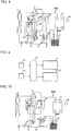

Classifications
-
- F—MECHANICAL ENGINEERING; LIGHTING; HEATING; WEAPONS; BLASTING
- F25—REFRIGERATION OR COOLING; COMBINED HEATING AND REFRIGERATION SYSTEMS; HEAT PUMP SYSTEMS; MANUFACTURE OR STORAGE OF ICE; LIQUEFACTION SOLIDIFICATION OF GASES
- F25B—REFRIGERATION MACHINES, PLANTS OR SYSTEMS; COMBINED HEATING AND REFRIGERATION SYSTEMS; HEAT PUMP SYSTEMS
- F25B13/00—Compression machines, plants or systems, with reversible cycle
-
- F—MECHANICAL ENGINEERING; LIGHTING; HEATING; WEAPONS; BLASTING
- F25—REFRIGERATION OR COOLING; COMBINED HEATING AND REFRIGERATION SYSTEMS; HEAT PUMP SYSTEMS; MANUFACTURE OR STORAGE OF ICE; LIQUEFACTION SOLIDIFICATION OF GASES
- F25B—REFRIGERATION MACHINES, PLANTS OR SYSTEMS; COMBINED HEATING AND REFRIGERATION SYSTEMS; HEAT PUMP SYSTEMS
- F25B1/00—Compression machines, plants or systems with non-reversible cycle
-
- F—MECHANICAL ENGINEERING; LIGHTING; HEATING; WEAPONS; BLASTING
- F25—REFRIGERATION OR COOLING; COMBINED HEATING AND REFRIGERATION SYSTEMS; HEAT PUMP SYSTEMS; MANUFACTURE OR STORAGE OF ICE; LIQUEFACTION SOLIDIFICATION OF GASES
- F25B—REFRIGERATION MACHINES, PLANTS OR SYSTEMS; COMBINED HEATING AND REFRIGERATION SYSTEMS; HEAT PUMP SYSTEMS
- F25B2313/00—Compression machines, plants or systems with reversible cycle not otherwise provided for
- F25B2313/027—Compression machines, plants or systems with reversible cycle not otherwise provided for characterised by the reversing means
- F25B2313/02741—Compression machines, plants or systems with reversible cycle not otherwise provided for characterised by the reversing means using one four-way valve
-
- F—MECHANICAL ENGINEERING; LIGHTING; HEATING; WEAPONS; BLASTING
- F25—REFRIGERATION OR COOLING; COMBINED HEATING AND REFRIGERATION SYSTEMS; HEAT PUMP SYSTEMS; MANUFACTURE OR STORAGE OF ICE; LIQUEFACTION SOLIDIFICATION OF GASES
- F25B—REFRIGERATION MACHINES, PLANTS OR SYSTEMS; COMBINED HEATING AND REFRIGERATION SYSTEMS; HEAT PUMP SYSTEMS
- F25B2400/00—Component parts or details not otherwise provided for in this subclass
- F25B2400/13—Economisers
-
- F—MECHANICAL ENGINEERING; LIGHTING; HEATING; WEAPONS; BLASTING
- F25—REFRIGERATION OR COOLING; COMBINED HEATING AND REFRIGERATION SYSTEMS; HEAT PUMP SYSTEMS; MANUFACTURE OR STORAGE OF ICE; LIQUEFACTION SOLIDIFICATION OF GASES
- F25B—REFRIGERATION MACHINES, PLANTS OR SYSTEMS; COMBINED HEATING AND REFRIGERATION SYSTEMS; HEAT PUMP SYSTEMS
- F25B2400/00—Component parts or details not otherwise provided for in this subclass
- F25B2400/16—Receivers
-
- F—MECHANICAL ENGINEERING; LIGHTING; HEATING; WEAPONS; BLASTING
- F25—REFRIGERATION OR COOLING; COMBINED HEATING AND REFRIGERATION SYSTEMS; HEAT PUMP SYSTEMS; MANUFACTURE OR STORAGE OF ICE; LIQUEFACTION SOLIDIFICATION OF GASES
- F25B—REFRIGERATION MACHINES, PLANTS OR SYSTEMS; COMBINED HEATING AND REFRIGERATION SYSTEMS; HEAT PUMP SYSTEMS
- F25B2600/00—Control issues
- F25B2600/25—Control of valves
- F25B2600/2509—Economiser valves
-
- F—MECHANICAL ENGINEERING; LIGHTING; HEATING; WEAPONS; BLASTING
- F25—REFRIGERATION OR COOLING; COMBINED HEATING AND REFRIGERATION SYSTEMS; HEAT PUMP SYSTEMS; MANUFACTURE OR STORAGE OF ICE; LIQUEFACTION SOLIDIFICATION OF GASES
- F25B—REFRIGERATION MACHINES, PLANTS OR SYSTEMS; COMBINED HEATING AND REFRIGERATION SYSTEMS; HEAT PUMP SYSTEMS
- F25B2700/00—Sensing or detecting of parameters; Sensors therefor
- F25B2700/19—Pressures
- F25B2700/193—Pressures of the compressor
- F25B2700/1933—Suction pressures
-
- F—MECHANICAL ENGINEERING; LIGHTING; HEATING; WEAPONS; BLASTING
- F25—REFRIGERATION OR COOLING; COMBINED HEATING AND REFRIGERATION SYSTEMS; HEAT PUMP SYSTEMS; MANUFACTURE OR STORAGE OF ICE; LIQUEFACTION SOLIDIFICATION OF GASES
- F25B—REFRIGERATION MACHINES, PLANTS OR SYSTEMS; COMBINED HEATING AND REFRIGERATION SYSTEMS; HEAT PUMP SYSTEMS
- F25B2700/00—Sensing or detecting of parameters; Sensors therefor
- F25B2700/21—Temperatures
- F25B2700/2115—Temperatures of a compressor or the drive means therefor
- F25B2700/21151—Temperatures of a compressor or the drive means therefor at the suction side of the compressor
Definitions
- the present invention relates to a refrigeration cycle of an intermediate injection type using HFO refrigerant, such as HFO-1234yF, HFO-1234ze or other low GWP refrigerants, and in particular, relates to improvement of operating efficiency thereof.
- HFO refrigerant such as HFO-1234yF, HFO-1234ze or other low GWP refrigerants
- the HFO refrigerant has the drawback that refrigerant at an outlet of a compressor has a low concentration, a low latent heat and a low discharge temperature. Therefore, when the refrigerant is used for the purpose of water heating or heating, reduction in COP, that is, reduction in operating efficiency was caused.
- suction SH superheat: a degree of superheat
- a relationship between suction SH (superheat: a degree of superheat) of refrigerant in an intermediate injection port of a compressor and a discharge temperature of refrigerant at an outlet of the compressor is as shown in Fig. 12 , and from this, it can be confirmed that the more the suction SH at the intermediate injection port of the compressor is, the more the discharge temperature of the refrigerant at the outlet of the compressor is, so that the coefficient of performance COP of the refrigeration cycle are improved with the increased sachtion SH at the intermediate injection port.
- Patent Literature 1 shows a conventional example of this type, and a general outline of the conventional vapor compression refrigeration cycle is as follows: a compressor having an injection port that serves as a refrigerant passage port at an intermediate part of a compression process that compresses sucked refrigerant and discharges it, a four-way valve, a heat-source side expansion device, a heat source side heat exchanger, a load-side expansion device and a load side heat exchanger, which are connected to form a circuit for circulating the refrigerant.
- Fig. 1 The configuration of the vapor compression refrigeration cycle of the above Patent Literature 1 will be described with reference to Fig. 1 of Embodiment 1.
- the configuration is substantially similar to the above Patent Literature 1 except for a specific component (a liquid receiver 4), and therefore, Fig. 1 is used for describing the configuration of the conventional art.
- the vapor compression refrigeration cycle is a vapor compression refrigeration cycle 100 including an intermediate injection port 16 for injecting a heated refrigerant into an inside of a compressor 1, with HFO as a new refrigerant, the vapor compression refrigeration cycle 100 being configured with a refrigeration cycle constituted by connecting, via refrigerant pipes, a compressor 1, a condenser 3 that is a heat exchanger on a high temperature side, an expansion valve 8 that is a second expanding device and an evaporator 7 that is a heat exchanger on a low temperature side, and a controller 18 that controls the refrigeration cycle, in which the compressor 1, the condenser 3, the expansion valve 8 and the evaporator 7 are connected with one another by the refrigerant pipes.
- a P-H diagram pressure-specific enthalpy line diagram
- the vertical axis indicates the pressure P of the refrigerant
- the horizontal axis indicates the specific enthalpy H of the refrigerant
- a saturation curve (C) composed of a saturated liquid line and a saturated vapor line and a P-H line (L) are depicted.
- the P-H line (L) corresponding to the above Patent Literature 1 will be generally described: a general outline thereof is a combination of two geometries, a portion of a substantially non-isosceles trapezoid (that may be referred to as "the former"), in which an upper base is longer than a lower base, and a portion of a parallelogram (that may be referred to as “the latter”) that is in contact with an upward-sloping portion to be contained in a portion of the non-isosceles trapezoid.
- the former a substantially non-isosceles trapezoid
- the latter a parallelogram
- the line p-d is configured with an upper base
- the line d-e is configured with a short side
- the line e-f is configured with a lower base (lower base ⁇ upper base)
- the line f-p is configured with a long side.
- the line a-p is configured with an upper base
- the line p-i is configured with a right side
- the line i-j is configured with a lower base
- the line j-a is configured with a left side.
- b and c are overlapped and are the same point; therefore, represented as b, c.
- a portion of a dot-and-dash line drawn inside the substantially non-isosceles trapezoid corresponds to the intermediate injection.
- the portion of the dot-and-dash line is configured with the line b-g parallel to the line d-e and the line g-h parallel to the line e-f.
- i, j are positioned on an extension of the line g-h.
- a to j positioned in Fig, 11 correspond to a to j of the refrigeration cycle in Fig. 1 , respectively.
- each of a to j indicates a position in configuration of the refrigeration cycle; however, in Fig. 11 , a to j indicate the states of the refrigeration cycle corresponding to those positions.
- the refrigerant changes from the state a to the state b positioned in the left direction in parallel to the horizontal axis along the solid line. This corresponds to, when the refrigerant passes through the condenser 3, rejecting heat from the refrigerant and reduction in enthalpy due to condensation from a gas state to a liquid state.
- c indicates the state of the refrigerant flowing through the entrance of the second expansion device 8, and c is plotted at the same position as b.
- the reason why b and c are plotted at the same position is that, though positions of the refrigerant flowing through the refrigerant pipe are different in the configuration shown in Fig. 1 , states of the refrigerant (pressure, specific entropy) are the same on the P-H diagram shown in Fig. 11 .
- the state c changes to the state d positioned in the left direction parallel to the horizontal axis along the solid line.
- a primary refrigerant pipe connected to the evaporator 7 and a auxirially refrigerant pipe (to be described later) connected to the injection port 16 exchange heat with each other.
- the primary refrigerant pipe discharges heat
- the auxirially refrigerant pipe absorbs heat.
- the refrigerant flowing through the primary refrigerant pipe corresponds to reduction in the enthalpy thereof.
- the refrigerant changes from the state d to the state e positioned in the lower direction in parallel to the vertical axis along the solid line. This corresponds to reduction in the pressure due to expansion of the refrigerant at the time when the refrigerant passes through the first expansion device 6,.
- the refrigerant changes from the state e to the state f positioned in the right direction in parallel to the horizontal axis along the solid line. This corresponds to absorption of heat by the refrigerant evaporating from the liquid state to the gas state and increase in enthalpy at the time when the refrigerant passes through the evaporator 7.
- the refrigerant changes from the state f to the state i positioned in the upper right direction along the upper-right sloping linear solid line. This corresponds to increase in the pressure and the enthalpy of the refrigerant due to condensation of the refrigerant to the intermediate pressure inside the compressor 1 by the compressor 1.
- the pressure Pf is increased to Pi and the specific enthalpy Hf is increased to Hi.
- the refrigerant changes from the state b (c) to the state g positioned in the lower direction parallel to the vertical axis along the dot-and-dash line. This corresponds to reduction in the pressure due to expansion of the refrigerant, when the refrigerant passes through the second expansion device 8,.
- the refrigerant changes from the state g to the state h positioned in the right direction parallel to the horizontal axis along the dot-and-dash line. This corresponds to absorption of heat by the refrigerant by means of heat exchange, and increase in enthalpy of the refrigerant when the refrigerant passes through the inside heat exchanger 5.
- h is on the saturation curve (C) or inside the line C.
- the states h, i and j are on the same line and the refrigerant changes from the state h toward the state j in the right direction parallel to the horizontal axis along the dot-and-dash line, and contrary to this, the refrigerant changes from the state i toward j to the state j positioned in the left direction parallel to the horizontal axis along the dot-and-dash line.
- This corresponds to averaging of enthalpy of the refrigerant in total as a result of mixing of two lines of refrigerant, the refrigerant supplied via the primary refrigerant pipe and the refrigerant supplied via the auxirially refrigerant pipe and thermal average thereof.
- the refrigerant changes from the state j to the state a positioned in the upper right direction along the upper-right sloping linear solid line.
- the compressor 1 compresses thereinside the refrigerant from intermediate pressure to high pressure, and thereby, the pressure and the enthalpy of the refrigerant are increased.
- the pressure Pa has benn increased fom the pressure Pj and the specific enthalpy Ha has been increased from the pressure Hj.
- Patent Literature 1 Japanese Unexamined Patent Application Publication No. 2013-15264 (Paragraph 0014, Fig. 1 )
- the refrigerant injected from the injection port 16 is not provided with sufficient suction SH.
- h is on the curve of the saturated vapor line
- j is slightly on the right side of the saturated vapor line and on the left side of the compression process of the P-H diagram related to the vapor compression refrigeration cycle. Therefore, the portion of the P-H diagram corresponding to the compression process does not exist at a proper position on the P-H diagram. In other words, this means that the controller 18 does not provide sufficient suction SH to the refrigerant inside the compressor 1 and cannot control the expansion valve 8 to cause j to be positioned on the right side of the saturated vapor line.
- operation by the conventional injection method naturally has its own limit to obtain heat for water heating, such as, a need to raise the temperature of circulation water on the second side up to a predetermined temperature (for example, 60 degrees C) by heating by use of heat generated from the condenser 3, which is a heat exchanger on the high temperature side.
- a predetermined temperature for example, 60 degrees C
- the present invention has been made to overcome the above-described problem, and, even when the HFO refrigerant that tends to decrease in the discharge temperature at the outlet side of the compressor is used, decrease in the discharge temperature of the refrigerant is prevented, to thereby obtain highly efficient refrigeration cycle for water heating and warming.
- a vapor compression refrigeration cycle of one aspect of the present invention is a vapor compression refrigeration cycle using HFO as refrigerant, the vapor compression refrigeration cycle being characterized by including: a compressor provided with an injection port for injecting refrigerant circulating in the vapor compression refrigeration cycle; a pressure sensor and a temperature sensor, provided adjacent to the injection port, that measure pressure and a temperature; an expansion device that performs opening and closing operation for compressing and expanding the refrigerant; and a controller that controls an opening degree of the expansion device based on the pressure and the temperature obtained by the pressure sensor and the temperature sensor, wherein the controller controls the expansion device for causing a portion, of a P-H diagram related to the vapor compression refrigeration cycle, corresponding to a compression process to be positioned outside a saturation curve composed of a saturated liquid line and a saturated vapor line, to be positioned below critical pressure, and to be positioned on a high enthalpy region side of the saturated vapor line.
- the vapor compression refrigeration cycle related to one aspect of the present invention is able to maintain the temperature of the refrigerant injected into the inside of the compressor of the intermediate injection type at a proper superheat state inside the compressor, and even when the HFO refrigerant is used, able to prevent decrease in the discharge temperature at the outlet of the compressor caused by injection into the inside of the compressor, and eventually, to improve operating efficiency (COP) of the refrigeration cycle.
- COP operating efficiency
- Fig. 1 shows the entire vapor compression refrigeration cycle 100 related to Embodiment 1 of the invention.
- a refrigeration cycle for water heating placed as a home water heater or a water heater for a building will be described as an example.
- Embodiment 1 will be specifically described based on Fig. 1 .
- the vapor compression refrigeration cycle 100 includes: a compressor 1 that compresses refrigerant; a four-way valve 2 that changes the flowing direction of the refrigerant; a condenser 3; a liquid receiver 4, which is a high-pressure container for storing high-pressure liquid refrigerant; an inside heat exchanger 5 that exchanges heat; an evaporator 7; a first expansion device 6 and a second expansion device 8 that expand the refrigerant; and an injection circuit 9 that heats the refrigerant injected from an injection port 16.
- a pressure sensor 13 and a temperature sensor 14 for measuring pressure and temperature of the refrigerant are provided, and further, a controller 18 that controls an opening degree of the second expansion device 8 is provided. Then, the controller 18 has a function of controlling the opening degree of the second expansion device 8 based on information of the refrigerant obtained by the pressure sensor 13 and the temperature sensor 14.
- the liquid receiver 4 is provided on the way of a route of a pipe connecting an output side of the condenser 3 and an inlet side of the second expansion device 8, and the refrigerant in a gas-liquid two-phase state flow accumulated in the liquid receiver 4 is branched from a primary refrigerant pipe, to be described later. Then, of gas-liquid two-phase flow accumulated in the liquid receiver 4, the refrigerant in one state flows into the inlet on the upper side of the inside heat exchanger 5, and the other one flows into the inlet of the lower side of the inside heat exchanger 5, via the second expansion device 8.
- two lines of refrigerant pipes namely, the primary refrigerant pipe that connects the liquid receiver 4 and the expansion device 6 and the auxirially refrigerant pipe that connects the liquid receiver 4 and the second expansion device 6 via the second expansion device 8, are arranged closely, and heat is exchanged between the refrigerant flowing through the primary refrigerant pipe and the refrigerant flowing through the auxirially refrigerant pipe with each other.
- expansion valves are used to decompress the refrigerant in the primary refrigerant pipe and the auxirially refrigerant pipe, respectively.
- the injection circuit 9 includes the auxirially refrigerant pipe and heats the refrigerant injected from the injection port 16 into the inside of the compressor 1.
- the injection port 16 is formed on a side surface of the compressor 1 to inject the refrigerant being the heated gas state into the inside of the compressor 1. Moreover, the pressure sensor 13 and the temperature sensor 14 are provided adjacent to the injection port 16 to measure the pressure and temperature of the refrigerant. Moreover, at the inlet of the inside heat exchanger 5, a temperature sensor 17 is provided. Further, an outside-air temperature sensor 15 is disposed close to the condenser 3 to measure the air temperature around the condenser 3.
- the controller 18 is connected to the second expansion device 8 via a communication line or others and controls opening and closing operation of the second expansion device 8 based on information of the refrigerant obtained by the pressure sensor 13 and the temperature sensor 14. For example, the controller 18 controls the opening degree of the second expansion device 8 so that the refrigerant injected from the compressor injection port is heated vapor with a degree of superheat of 20 degrees C or more and a pressure higher than a low pressure at the compressor by a difference of no less than 0.35 times a difference between a high pressure and the low pressure in a compression process of the compressor.
- the condenser 3 corresponds to the heat exchanger on the high temperature side, and the high heat obtained in the condenser 3 is used as a high temperature heat source on the second side.
- the evaporator 7 corresponds to the heat exchanger on the low temperature side, and the low heat obtained in the evaporator 7 is used as a low temperature heat source on the second side.
- the sketch of the P-H line (L) is the same in the point that it is a combination of two geometries, a portion of a substantially non-isosceles trapezoid (former), in which an upper base is longer than a lower base, and a portion on the right of a parallelogram (latter) that is in contact with an upward-sloping portion of the non-isosceles trapezoid; however, there is a difference that the latter is outside of the former.
- first period a period from a to g
- second period a period from g to h
- third period a period from h to a
- the refrigerant changes from the state g to the state h positioned in the right direction in parallel to the horizontal axis along the dot-and-dash line. This corresponds to absorption of heat by the refrigerant by means of heat exchange, and increase in enthalpy of the refrigerant at the time when the refrigerant passes through the inside heat exchanger 5.
- h is on the outside of the saturation curve (C).
- the refrigerant changes from the state g in the right direction parallel to the horizontal axis along the dot-and-dash line greater than that described in Fig. 11 .
- the states h and j are shifted to the high enthalpy region side (the right side) of the conventional P-H diagram described by using Fig. 11 before. In other words, it can be found that the specific enthalpy of the refrigerant is increased inside the compressor 1 in Embodiment 1 of the present invention.
- this is nothing other than the controller 18 that provides sufficient suction SH to the refrigerant inside the compressor 1 and is able to control the expansion valve 8 to cause the point j to be positioned on the right side of the saturated vapor line.
- a portion of a line a-p from the point a to the point p indicates the rise ⁇ H of the discharge temperature of the refrigerant (see Fig. 3 ).
- Adjustment in refrigerant temperature by control of the opening degree of the second expansion device 8 in the vapor compression refrigeration cycle 100 can be achieved by carrying out processing procedures shown in Fig. 4 (hereinafter, step S1 to step S5). Description will be given with reference to Fig. 4 .
- the outside-air temperature sensor 15 detects air temperature around the condenser 3 (step S1).
- the controller 18 detects the pressure value of the refrigerant from the pressure sensor 13, and obtains the temperature of the refrigerant from the temperature sensor 15. Thereafter, based on the pressure value obtained from the pressure sensor 13, the controller 18 computes a saturation temperature of the refrigerant at the pressure (step S2).
- the controller 18 compares the saturation temperature with the temperature obtained by the temperature sensor 17 placed at the inlet of the inside heat exchanger 5, to thereby calculate the degree of superheat SH of the refrigerant (step S3).
- the degree of superheat SH is a difference in temperature between the temperature at the inlet side of the inside heat exchanger 5 and the temperature at the outlet side thereof.
- the degree of superheat SH is compared with a target value of degree of superheat SHs, which is a preset target value, and based on the result of comparison, the controller 18 determines the opening degree of the second expansion device 8.
- step S4 the controller 18 determines the opening degree of the second expansion device 8 and directs the determination result to the second expansion device 8.
- step S4 after carrying out the opening degree control of the second expansion device 8, the controller 18 determines whether or not further control is required. In other words, whether or not continuous operation of the vapor compression refrigeration cycle 100 is required is determined, and when the continuous operation is further required, the process proceeds to YES to return to S1, whereas, when the continuous operation is not required, the process proceeds to NO, to thereby finish the opening degree control of the second expansion device 8 by the controller 18 (step S5).
- step S5 is a step to determine whether or not the opening degree of the second expansion device 8 is computed again.
- Embodiment 2 newly provides an air-to-refrigerant heat exchanger 10, which is a second heating unit, close to the auxirially refrigerant pipe communicating to the injection port 16, and accordingly, carries out heating of the refrigerant injected into the inside of the compressor 1 from the injection port 16 by use of two types of heating units, namely, the inside heat exchanger 5 and the air-to-refrigerant heat exchanger 10.
- Embodiment 2 in addition to use of the two types of heating units, a fan is included in the air-to-refrigerant heat exchanger 10, which is the second heating unit, to perform rotation speed control by an inverter. Therefore, it is possible to obtain a sufficient heat exchanging amount while designing the heat exchanger compactly, and to stably supply the superheat refrigerant of a desired temperature from the injection port 16 of the compressor.
- the states h and j are shifted to the high enthalpy region side (the right side) of the P-H diagram in Embodiment 1.
- the refrigeration cycle related to Embodiment 2 is able to omit installation of the fan by increasing the heat exchanging area of the air-to-refrigerant heat exchanger 10.
- discharged heat from a control board may be used as a heat source (refer to Fig. 7 ). In this case, effect of adding further degree of superheat SH is expected.
- a circulation heat exchanger 11, which is a second heating unit, is provided at the same position as the air-to-refrigerant heat exchanger 10 of Embodiment 2 to replace thereof.
- the circulation heat exchanger 11, which is the second heating unit that preforms heat exchange with liquid (air or brine) recovering the discharged heat of the compressor 1, and a pump 12 are newly provided, and accordingly, heating of the refrigerant injected into the inside of the compressor 1 from the injection port 16 by use of two types of heating units, namely, the inside heat exchanger 5 and the circulation heat exchanger 11, is carried out.
- the circulation heat exchanger 11 heats the refrigerant flowing through the auxirially refrigerant pipe by utilizing the liquid (air or brine) recovering the discharged heat from the compressor 1 close to the auxirially refrigerant pipe.
- the pump 12 is disposed at the middle of the pipe connecting the compressor 1 and the circulation heat exchanger 11 to circulate the liquid (air or brine) recovering the discharged heat from the compressor 1.
- Embodiment 3 the states h and j are shifted to the high enthalpy region side (the right side) of the P-H diagram in Embodiment 1.
- Embodiment 3 by performing heat exchange by directly winding the injection circuit 9 around the compressor 1 as a modified example of Embodiment 3, it is possible to omit the circulation heat exchanger 11, the pump 12, and a liquid circuit configured with water (or brine) attached thereto.
- the modified example of Embodiment 3 is a liquid-winding type, the heat source thereof also remains the liquid-heating type.
- Embodiment 4 adds an outflow path for gas refrigerant so that, of the refrigerant in the state of gas-liquid two-phase flow accumulated in the liquid receiver 4, a gas portion in a gas phase state that has become heated vapor (gas refrigerant) flows into an inlet side of the second expansion device 8 from an upper portion of the liquid receiver 4, to thereby improve the heat exchange efficiency in the inside heat exchanger 5, which is a single heating unit.
- Embodiment 4 a difference in configuration from Embodiment 1 to Embodiment 3 is the point that the outflow path for the gas refrigerant is newly and additionally provided to the upper portion of the liquid receiver 4.
- One end of the refrigerant pipe is in contact with the proximity of a liquid level in the upper portion of the liquid receiver 4, and the other end is connected to the inlet side of the second expansion device 8.
- the gas portion in a gas phase state that has become heated vapor flows into the inlet side of the second expansion device 8, and then flows into the entrance of the upper side of the inside heat exchanger 5, via the second expansion device 8, whereas, the liquid portion flows into the entrance of the lower side of the inside heat exchanger 5.
- heat exchange is carried out between the refrigerant flowing through the auxirially refrigerant pipe and the refrigerant flowing through the primary refrigerant pipe.
- Embodiment 4 the states h and j are shifted to the high enthalpy region side (the right side) of the P-H diagram in Embodiment 1 to Embodiment 3.
- the temperature of the refrigerant subjected to intermediate injection into the compressor is maintained at a proper superheat state, and thereby it is possible to prevent decrease in the discharge temperature at the outlet of the compressor, and eventually, to improve the operating efficiency (COP) of the refrigeration cycle.
- COP operating efficiency
- the vapor compression refrigeration cycle of the present invention may be adopted not only to the field of using water heating, but also to other fields.
Landscapes
- Engineering & Computer Science (AREA)
- Physics & Mathematics (AREA)
- Mechanical Engineering (AREA)
- Thermal Sciences (AREA)
- General Engineering & Computer Science (AREA)
- Heat-Pump Type And Storage Water Heaters (AREA)
- Compression-Type Refrigeration Machines With Reversible Cycles (AREA)
Abstract
Description
- The present invention relates to a refrigeration cycle of an intermediate injection type using HFO refrigerant, such as HFO-1234yF, HFO-1234ze or other low GWP refrigerants, and in particular, relates to improvement of operating efficiency thereof.
- Conventionally, for example, use of specified chlorofluorocarbons employed in water heaters or air conditioners has caused concern about destruction of the ozone layer or increased global warming, to be thereby subjected to regulations. In Europe, switching to the low GWP refrigerant is being pursued by, for example, F-gas Regulation. Based on such background, from now on, it is expected that the existing refrigerants, such as HFC or others, will be replaced with HFO refrigerants.
- However, as compared to the conventional HFC refrigerant, the HFO refrigerant has the drawback that refrigerant at an outlet of a compressor has a low concentration, a low latent heat and a low discharge temperature. Therefore, when the refrigerant is used for the purpose of water heating or heating, reduction in COP, that is, reduction in operating efficiency was caused.
- By the way, in regard to increase in operating efficiency of the refrigeration cycle, as a method thereof, improvement in refrigerant efficiency by the intermediate injection type is made, and improvement of COP (Coefficient of Performance) by an intermediate injection circuit in the refrigeration cycle caused thereby is achieved by improvement in compressor efficiency and improvement in cycle efficiency. In general, to improve the cycle efficiency, the refrigerant temperature is raised. When the refrigerant temperature is raised, a refrigerant circulation amount in a gas cooler side is increased, and thereby heating capacity and the COP are improved. As a conceivable specific method to achieve this is, for example, an intermediate injection port entrance is provided on a side surface of a compressor, and refrigerant in a heated gas state is injected from the part.
- As to the intermediate injection type, a relationship between suction SH (superheat: a degree of superheat) of refrigerant in an intermediate injection port of a compressor and a discharge temperature of refrigerant at an outlet of the compressor is as shown in
Fig. 12 , and from this, it can be confirmed that the more the suction SH at the intermediate injection port of the compressor is, the more the discharge temperature of the refrigerant at the outlet of the compressor is, so that the coefficient of performance COP of the refrigeration cycle are improved with the increased sachtion SH at the intermediate injection port. -
Patent Literature 1 shows a conventional example of this type, and a general outline of the conventional vapor compression refrigeration cycle is as follows: a compressor having an injection port that serves as a refrigerant passage port at an intermediate part of a compression process that compresses sucked refrigerant and discharges it, a four-way valve, a heat-source side expansion device, a heat source side heat exchanger, a load-side expansion device and a load side heat exchanger, which are connected to form a circuit for circulating the refrigerant. - The configuration of the vapor compression refrigeration cycle of the
above Patent Literature 1 will be described with reference toFig. 1 ofEmbodiment 1. Basically, the configuration is substantially similar to theabove Patent Literature 1 except for a specific component (a liquid receiver 4), and therefore,Fig. 1 is used for describing the configuration of the conventional art. - The vapor compression refrigeration cycle is a vapor
compression refrigeration cycle 100 including anintermediate injection port 16 for injecting a heated refrigerant into an inside of acompressor 1, with HFO as a new refrigerant, the vaporcompression refrigeration cycle 100 being configured with a refrigeration cycle constituted by connecting, via refrigerant pipes, acompressor 1, acondenser 3 that is a heat exchanger on a high temperature side, anexpansion valve 8 that is a second expanding device and anevaporator 7 that is a heat exchanger on a low temperature side, and acontroller 18 that controls the refrigeration cycle, in which thecompressor 1, thecondenser 3, theexpansion valve 8 and theevaporator 7 are connected with one another by the refrigerant pipes. - Moreover, by using a P-H diagram (pressure-specific enthalpy line diagram) in
Fig. 11 , operation of the vapor compression refrigeration cycle according to theabove Patent Literature 1 will be described. In the P-H diagram, the vertical axis indicates the pressure P of the refrigerant, and the horizontal axis indicates the specific enthalpy H of the refrigerant, and in theFig. 11 , a saturation curve (C) composed of a saturated liquid line and a saturated vapor line and a P-H line (L) are depicted. - First, the P-H line (L) corresponding to the
above Patent Literature 1 will be generally described: a general outline thereof is a combination of two geometries, a portion of a substantially non-isosceles trapezoid (that may be referred to as "the former"), in which an upper base is longer than a lower base, and a portion of a parallelogram (that may be referred to as "the latter") that is in contact with an upward-sloping portion to be contained in a portion of the non-isosceles trapezoid. - Hereinafter, in the former, the line p-d is configured with an upper base, the line d-e is configured with a short side, the line e-f is configured with a lower base (lower base < upper base) and the line f-p is configured with a long side. In the latter, the line a-p is configured with an upper base, the line p-i is configured with a right side, the line i-j is configured with a lower base and the line j-a is configured with a left side. Note that b and c are overlapped and are the same point; therefore, represented as b, c.
- Moreover, a portion of a dot-and-dash line drawn inside the substantially non-isosceles trapezoid corresponds to the intermediate injection. The portion of the dot-and-dash line is configured with the line b-g parallel to the line d-e and the line g-h parallel to the line e-f. Moreover, i, j are positioned on an extension of the line g-h.
- Here, a to j positioned in
Fig, 11 correspond to a to j of the refrigeration cycle inFig. 1 , respectively. InFig. 1 , each of a to j indicates a position in configuration of the refrigeration cycle; however, inFig. 11 , a to j indicate the states of the refrigeration cycle corresponding to those positions. - In
Fig. 11 , "a" (hereafter the quotation may be omitted) indicates the state of refrigerant corresponding to the outlet of thecompressor 1 ; the pressure is Pa, and the specific enthalpy is Ha at "a". - During the process from a to b, the refrigerant changes from the state a to the state b positioned in the left direction in parallel to the horizontal axis along the solid line. This corresponds to, when the refrigerant passes through the
condenser 3, rejecting heat from the refrigerant and reduction in enthalpy due to condensation from a gas state to a liquid state. In the state b (c), as compared to the state a, the pressure Pb is not changed, that is, Pb (Pc) = Pa, the specific enthalpy is reduced to Hb (Hc). - Then, c indicates the state of the refrigerant flowing through the entrance of the
second expansion device 8, and c is plotted at the same position as b. Here, in the P-H diagram inFig. 11 , the reason why b and c are plotted at the same position is that, though positions of the refrigerant flowing through the refrigerant pipe are different in the configuration shown inFig. 1 , states of the refrigerant (pressure, specific entropy) are the same on the P-H diagram shown inFig. 11 . - During the process from c to d, the state c changes to the state d positioned in the left direction parallel to the horizontal axis along the solid line. This is because, when the refrigerant passes through the
inside heat exchanger 5, a primary refrigerant pipe connected to theevaporator 7 and a auxirially refrigerant pipe (to be described later) connected to theinjection port 16 exchange heat with each other. In other words, the primary refrigerant pipe discharges heat, and the auxirially refrigerant pipe absorbs heat. The refrigerant flowing through the primary refrigerant pipe corresponds to reduction in the enthalpy thereof. In the state d, as compared to the state c, the pressure Pd is not changed, that is, Pd = Pc, and the specific enthalpy is reduced to Hd. - During the process from d to e, the refrigerant changes from the state d to the state e positioned in the lower direction in parallel to the vertical axis along the solid line. This corresponds to reduction in the pressure due to expansion of the refrigerant at the time when the refrigerant passes through the
first expansion device 6,. In the state e, as compared to the state d, the specific enthalpy is not changed, that is, He = Pa, and the pressure is reduced to Pe. - During the period from e to f, the refrigerant changes from the state e to the state f positioned in the right direction in parallel to the horizontal axis along the solid line. This corresponds to absorption of heat by the refrigerant evaporating from the liquid state to the gas state and increase in enthalpy at the time when the refrigerant passes through the
evaporator 7. In the state f, as compared to the state e, the pressure Pf is not changed, that is, Pf = Pe, and the specific enthalpy is increased to Hf. - During the period from f to i, the refrigerant changes from the state f to the state i positioned in the upper right direction along the upper-right sloping linear solid line. This corresponds to increase in the pressure and the enthalpy of the refrigerant due to condensation of the refrigerant to the intermediate pressure inside the
compressor 1 by thecompressor 1. In the state i, the pressure Pf is increased to Pi and the specific enthalpy Hf is increased to Hi. - Similarly, during the process from b (c) corresponding to the intermediate injection to g, the refrigerant changes from the state b (c) to the state g positioned in the lower direction parallel to the vertical axis along the dot-and-dash line. This corresponds to reduction in the pressure due to expansion of the refrigerant, when the refrigerant passes through the
second expansion device 8,. In the state g as compared to the state c, the specific enthalpy is not changed, that is, Hg = Hc, and the pressure is reduced to Pg. - During the process from g to h, the refrigerant changes from the state g to the state h positioned in the right direction parallel to the horizontal axis along the dot-and-dash line. This corresponds to absorption of heat by the refrigerant by means of heat exchange, and increase in enthalpy of the refrigerant when the refrigerant passes through the
inside heat exchanger 5. In the state h, as compared to the state g, the pressure Ph is not changed, that is, Ph = Pg, and the specific enthalpy is increased to Hh. Here, h is on the saturation curve (C) or inside the line C. - During the process from h, i to j, the states h, i and j are on the same line and the refrigerant changes from the state h toward the state j in the right direction parallel to the horizontal axis along the dot-and-dash line, and contrary to this, the refrigerant changes from the state i toward j to the state j positioned in the left direction parallel to the horizontal axis along the dot-and-dash line. This corresponds to averaging of enthalpy of the refrigerant in total as a result of mixing of two lines of refrigerant, the refrigerant supplied via the primary refrigerant pipe and the refrigerant supplied via the auxirially refrigerant pipe and thermal average thereof. In the state j, as compared to the state i, the pressure Pj is not changed, that is, Pj = Ph = Pi, and the specific enthalpy Hj is an average value of Hh and Hi.
- During the process from j to a, the refrigerant changes from the state j to the state a positioned in the upper right direction along the upper-right sloping linear solid line. The
compressor 1 compresses thereinside the refrigerant from intermediate pressure to high pressure, and thereby, the pressure and the enthalpy of the refrigerant are increased. In the state a, the pressure Pa has benn increased fom the pressure Pj and the specific enthalpy Ha has been increased from the pressure Hj. - This brings about the state in which the pressure is Pa and the specific enthalpy is Ha and the refrigerant returns to the original state a of refrigerant flowing at the outlet of the
compressor 1, to thereby complete 1 cycle. - Note that, as is clear from the above description, in the above P-H line (L) diagram, there exist two compression processes, namely, the first compression process during the period from f to i and the second compression process during the period from j to a, and a portion commonly corresponding to the two compression processes is simply referred to as a compression process.
- Patent Literature 1: Japanese Unexamined Patent Application Publication No.
2013-15264 Fig. 1 ) - However, in the conventional intermediate injection type shown in
Fig. 11 , the refrigerant injected from theinjection port 16 is not provided with sufficient suction SH. In other words, inFig. 11 , h is on the curve of the saturated vapor line, whereas, j is slightly on the right side of the saturated vapor line and on the left side of the compression process of the P-H diagram related to the vapor compression refrigeration cycle. Therefore, the portion of the P-H diagram corresponding to the compression process does not exist at a proper position on the P-H diagram. In other words, this means that thecontroller 18 does not provide sufficient suction SH to the refrigerant inside thecompressor 1 and cannot control theexpansion valve 8 to cause j to be positioned on the right side of the saturated vapor line. - Therefore, operation by the conventional injection method naturally has its own limit to obtain heat for water heating, such as, a need to raise the temperature of circulation water on the second side up to a predetermined temperature (for example, 60 degrees C) by heating by use of heat generated from the
condenser 3, which is a heat exchanger on the high temperature side. - In this manner, since the discharge temperature at the outlet of the compressor sharply decreases, the refrigeration cycle using HFO refrigerant as new refrigerant instead of the conventional HFC, there is a natural limit in water heating capacity, and accordingly, when the injection amount is determined in accordance with the conventional suggestion, it is impossible to obtain sufficient performance improvement effect and reliability improvement effect by intermediate injection.
- The present invention has been made to overcome the above-described problem, and, even when the HFO refrigerant that tends to decrease in the discharge temperature at the outlet side of the compressor is used, decrease in the discharge temperature of the refrigerant is prevented, to thereby obtain highly efficient refrigeration cycle for water heating and warming.
- A vapor compression refrigeration cycle of one aspect of the present invention is a vapor compression refrigeration cycle using HFO as refrigerant, the vapor compression refrigeration cycle being characterized by including: a compressor provided with an injection port for injecting refrigerant circulating in the vapor compression refrigeration cycle; a pressure sensor and a temperature sensor, provided adjacent to the injection port, that measure pressure and a temperature; an expansion device that performs opening and closing operation for compressing and expanding the refrigerant; and a controller that controls an opening degree of the expansion device based on the pressure and the temperature obtained by the pressure sensor and the temperature sensor, wherein the controller controls the expansion device for causing a portion, of a P-H diagram related to the vapor compression refrigeration cycle, corresponding to a compression process to be positioned outside a saturation curve composed of a saturated liquid line and a saturated vapor line, to be positioned below critical pressure, and to be positioned on a high enthalpy region side of the saturated vapor line.
- The vapor compression refrigeration cycle related to one aspect of the present invention is able to maintain the temperature of the refrigerant injected into the inside of the compressor of the intermediate injection type at a proper superheat state inside the compressor, and even when the HFO refrigerant is used, able to prevent decrease in the discharge temperature at the outlet of the compressor caused by injection into the inside of the compressor, and eventually, to improve operating efficiency (COP) of the refrigeration cycle.
-
- [
Fig. 1] Fig. 1 is a circuit diagram of a vaporcompression refrigeration cycle 100showing Embodiment 1 of the present invention. - [
Fig. 2] Fig. 2 is a P-H diagram showing a state of refrigerant related toEmbodiment 1. - [
Fig. 3] Fig. 3 is a P-H diagram showing an image of rising in a discharge temperature when heated refrigerant is supplied to anintermediate injection port 16. - [
Fig. 4] Fig. 4 is a flow diagram of opening degree control of asecond expansion device 8 related toEmbodiment 1. - [
Fig. 5] Fig. 5 is a circuit diagram of a vaporcompression refrigeration cycle 200 when an air-to-refrigerant heat exchanger 10 is used related toEmbodiment 2. - [
Fig. 6] Fig. 6 is a block diagram showing an overview of flow of a signal related toEmbodiment 2. - [
Fig. 7] Fig. 7 is a circuit diagram of a vaporcompression refrigeration cycle 300 when heat discharged from a control board is used related to a modified example ofEmbodiment 2. - [
Fig. 8] Fig. 8 is a circuit diagram of a vaporcompression refrigeration cycle 400 when heat discharged from acompressor 1 is used related toEmbodiment 3. - [
Fig. 9] Fig. 9 is a block diagram showing an overview of flow of a signal related toEmbodiment 3. - [
Fig. 10] Fig. 10 is a circuit diagram of a vaporcompression refrigeration cycle 400 when gas refrigerant injection inside aliquid receiver 4 is used related toEmbodiment 4. - [
Fig. 11] Fig. 11 is a P-H diagram showing a state of refrigerant related to aconventional injection circuit 9. - [
Fig. 12] Fig. 12 shows a relationship between suction SH and COP (Coefficient of Performance) in theintermediate injection port 16. -
Fig. 1 shows the entire vaporcompression refrigeration cycle 100 related toEmbodiment 1 of the invention. Hereinafter, a refrigeration cycle for water heating placed as a home water heater or a water heater for a building will be described as an example. - Prior to specific description of a configuration in detail, first, the vapor
compression refrigeration cycle 100 and main circuits constituting the main circuits will be described. - Hereinafter,
Embodiment 1 will be specifically described based onFig. 1 . - The vapor
compression refrigeration cycle 100 includes: acompressor 1 that compresses refrigerant; a four-way valve 2 that changes the flowing direction of the refrigerant; acondenser 3; aliquid receiver 4, which is a high-pressure container for storing high-pressure liquid refrigerant; aninside heat exchanger 5 that exchanges heat; anevaporator 7; afirst expansion device 6 and asecond expansion device 8 that expand the refrigerant; and aninjection circuit 9 that heats the refrigerant injected from aninjection port 16. - Moreover, in the proximity of the entrance of the
injection port 16, apressure sensor 13 and atemperature sensor 14 for measuring pressure and temperature of the refrigerant are provided, and further, acontroller 18 that controls an opening degree of thesecond expansion device 8 is provided. Then, thecontroller 18 has a function of controlling the opening degree of thesecond expansion device 8 based on information of the refrigerant obtained by thepressure sensor 13 and thetemperature sensor 14. - The
liquid receiver 4 is provided on the way of a route of a pipe connecting an output side of thecondenser 3 and an inlet side of thesecond expansion device 8, and the refrigerant in a gas-liquid two-phase state flow accumulated in theliquid receiver 4 is branched from a primary refrigerant pipe, to be described later. Then, of gas-liquid two-phase flow accumulated in theliquid receiver 4, the refrigerant in one state flows into the inlet on the upper side of theinside heat exchanger 5, and the other one flows into the inlet of the lower side of theinside heat exchanger 5, via thesecond expansion device 8. - Inside the
heat exchanger 5, two lines of refrigerant pipes, namely, the primary refrigerant pipe that connects theliquid receiver 4 and theexpansion device 6 and the auxirially refrigerant pipe that connects theliquid receiver 4 and thesecond expansion device 6 via thesecond expansion device 8, are arranged closely, and heat is exchanged between the refrigerant flowing through the primary refrigerant pipe and the refrigerant flowing through the auxirially refrigerant pipe with each other. As a result, heat is rejected from the primary refrigerant pipe to the auxirially refrigerant pipe and heat from the auxirially refrigerant pipe is absorbed by the primary refrigerant pipe, and accordingly, the temperature of the refrigerant flowing through the primary refrigerant pipe is decreased and the temperature of the refrigerant flowing through the auxirially refrigerant pipe is raised. - As the
first expansion device 6 and thesecond expansion device 8, expansion valves are used to decompress the refrigerant in the primary refrigerant pipe and the auxirially refrigerant pipe, respectively. Theinjection circuit 9 includes the auxirially refrigerant pipe and heats the refrigerant injected from theinjection port 16 into the inside of thecompressor 1. - The
injection port 16 is formed on a side surface of thecompressor 1 to inject the refrigerant being the heated gas state into the inside of thecompressor 1. Moreover, thepressure sensor 13 and thetemperature sensor 14 are provided adjacent to theinjection port 16 to measure the pressure and temperature of the refrigerant. Moreover, at the inlet of theinside heat exchanger 5, atemperature sensor 17 is provided. Further, an outside-air temperature sensor 15 is disposed close to thecondenser 3 to measure the air temperature around thecondenser 3. - Then, the
controller 18 is connected to thesecond expansion device 8 via a communication line or others and controls opening and closing operation of thesecond expansion device 8 based on information of the refrigerant obtained by thepressure sensor 13 and thetemperature sensor 14. For example, thecontroller 18 controls the opening degree of thesecond expansion device 8 so that the refrigerant injected from the compressor injection port is heated vapor with a degree of superheat of 20 degrees C or more and a pressure higher than a low pressure at the compressor by a difference of no less than 0.35 times a difference between a high pressure and the low pressure in a compression process of the compressor. - Note that the
condenser 3 corresponds to the heat exchanger on the high temperature side, and the high heat obtained in thecondenser 3 is used as a high temperature heat source on the second side. Similarly, theevaporator 7 corresponds to the heat exchanger on the low temperature side, and the low heat obtained in theevaporator 7 is used as a low temperature heat source on the second side. - First, a sketch of the P-H diagram (L) of the embodiment will be described.
- Though operation of the vapor compression refrigeration cycle according to the present invention will be described later, since a general outline thereof is the same as the conventional P-H diagram except that the states h and j shown in
Fig. 11 are shifted to the right side (shifted to a high enthalpy region side), description thereof is omitted, and points of difference from the conventional art will be mainly described with reference toFig. 2 . - The sketch of the P-H line (L) is the same in the point that it is a combination of two geometries, a portion of a substantially non-isosceles trapezoid (former), in which an upper base is longer than a lower base, and a portion on the right of a parallelogram (latter) that is in contact with an upward-sloping portion of the non-isosceles trapezoid; however, there is a difference that the latter is outside of the former.
- Moreover, although the point that a to j positioned in
Fig. 2 (the states of the refrigerant) correspond to a to j in the refrigeration cycle inFig. 1 (positions on the configuration of the refrigeration cycle), respectively, is the same, there is a difference in the point that the operation of the vapor compression refrigeration cycle according to the present invention corresponds toFig. 2 . - Consideration will be given by dividing the operating period of the vapor compression refrigeration cycle according to the present invention into three periods; a first period (a period from a to g), a second period (a period from g to h) and a third period (a period from h to a). Of these, the first period and the third period are the same as before. Here, description will be given with a focus on the second period (the period from g to h), which is different from before.
- During the process from g to h, the refrigerant changes from the state g to the state h positioned in the right direction in parallel to the horizontal axis along the dot-and-dash line. This corresponds to absorption of heat by the refrigerant by means of heat exchange, and increase in enthalpy of the refrigerant at the time when the refrigerant passes through the
inside heat exchanger 5. The state h corresponds to, as compared to the state g, constancy in the pressure Ph, that is, Ph = Pg, and increase in the specific enthalpy Hh. Here, h is on the outside of the saturation curve (C). - In other words, during the period from g to h, the refrigerant changes from the state g in the right direction parallel to the horizontal axis along the dot-and-dash line greater than that described in
Fig. 11 . This indicates that the refrigerant absorbs more heat than that described inFig. 11 by heat exchange when the refrigerant passes through theinside heat exchanger 5, and the refrigerant having absorbs heat is supplied from theinjection port 16, to thereby further increase enthalpy of the refrigerant inside thecompressor 1. - Further, to describe specifically, the states h and j are shifted to the high enthalpy region side (the right side) of the conventional P-H diagram described by using
Fig. 11 before. In other words, it can be found that the specific enthalpy of the refrigerant is increased inside thecompressor 1 inEmbodiment 1 of the present invention. - As described above, of the P-H diagram in
Fig. 2 related to the vaporcompression refrigeration cycle 100, both of the portions corresponding to those two compression process exist in a region satisfying the following three conditions. - Condition 1: positioned outside the saturation curve (C) composed of the saturated liquid line and the saturated vapor line.
- Condition 2: positioned below critical pressure. (Put another way, the states h and j on the P-H diagram (L) are below the states a and p.)
- Condition 3: positioned sufficiently on the high enthalpy region side of the saturated vapor line. (Put another way, the states h and j on the P-H diagram (L) are on the right side of the state i.)
- In other words, this is nothing other than the
controller 18 that provides sufficient suction SH to the refrigerant inside thecompressor 1 and is able to control theexpansion valve 8 to cause the point j to be positioned on the right side of the saturated vapor line. - Moreover, a portion of a line a-p from the point a to the point p indicates the rise ΔH of the discharge temperature of the refrigerant (see
Fig. 3 ). - Adjustment in refrigerant temperature by control of the opening degree of the
second expansion device 8 in the vaporcompression refrigeration cycle 100 can be achieved by carrying out processing procedures shown inFig. 4 (hereinafter, step S1 to step S5). Description will be given with reference toFig. 4 . - When an operation command of the vapor
compression refrigeration cycle 100 turns ON, the outside-air temperature sensor 15 detects air temperature around the condenser 3 (step S1). - The
controller 18 detects the pressure value of the refrigerant from thepressure sensor 13, and obtains the temperature of the refrigerant from thetemperature sensor 15. Thereafter, based on the pressure value obtained from thepressure sensor 13, thecontroller 18 computes a saturation temperature of the refrigerant at the pressure (step S2). - When computation of the saturation temperature of the refrigerant is completed at the above step S2, the
controller 18 compares the saturation temperature with the temperature obtained by thetemperature sensor 17 placed at the inlet of theinside heat exchanger 5, to thereby calculate the degree of superheat SH of the refrigerant (step S3). Here, the degree of superheat SH is a difference in temperature between the temperature at the inlet side of theinside heat exchanger 5 and the temperature at the outlet side thereof. - Next, the degree of superheat SH is compared with a target value of degree of superheat SHs, which is a preset target value, and based on the result of comparison, the
controller 18 determines the opening degree of thesecond expansion device 8. - As a result of the comparison of the degree of superheat SH and the target value of degree of superheat SHs, when the target value of degree of superheat SHs is larger than the degree of superheat SH (target value of degree of superheat SHs > degree of superheat SH), control is exercised to reduce the opening degree of the
second expansion device 8, whereas, when the target value of degree of superheat SHs is smaller than the degree of superheat SH (target value of degree of superheat SHs < degree of superheat SH), control is exercised to increase the opening degree of the second expansion device 8 (step S4). - Here, in step S4, the
controller 18 determines the opening degree of thesecond expansion device 8 and directs the determination result to thesecond expansion device 8. - In the above step S4, after carrying out the opening degree control of the
second expansion device 8, thecontroller 18 determines whether or not further control is required. In other words, whether or not continuous operation of the vaporcompression refrigeration cycle 100 is required is determined, and when the continuous operation is further required, the process proceeds to YES to return to S1, whereas, when the continuous operation is not required, the process proceeds to NO, to thereby finish the opening degree control of thesecond expansion device 8 by the controller 18 (step S5). - Here, step S5 is a step to determine whether or not the opening degree of the
second expansion device 8 is computed again. - Hereinafter, the processes of the above steps S1 to S5 are repeatedly carried out.
- In a vapor
compression refrigeration cycle 200showing Embodiment 2 of the invention, since the system configuration, the P-H diagram and the control flow are substantially the same as those ofEmbodiment 1, description thereof is omitted, and different points fromEmbodiment 1 will be mainly described with reference toFig. 5 . -
Embodiment 2 newly provides an air-to-refrigerant heat exchanger 10, which is a second heating unit, close to the auxirially refrigerant pipe communicating to theinjection port 16, and accordingly, carries out heating of the refrigerant injected into the inside of thecompressor 1 from theinjection port 16 by use of two types of heating units, namely, theinside heat exchanger 5 and the air-to-refrigerant heat exchanger 10. - Therefore, it becomes easy to add the degree of superheat SH to the HFO refrigerant flowing through the auxirially refrigerant pipe communicating to the
injection port 16, and accordingly, as compared toEmbodiment 1, it is possible to prevent decrease in the discharge temperature at the outlet side of the compressor, and to realize further efficient refrigeration cycle for water heating and warming. - Further, in
Embodiment 2, in addition to use of the two types of heating units, a fan is included in the air-to-refrigerant heat exchanger 10, which is the second heating unit, to perform rotation speed control by an inverter. Therefore, it is possible to obtain a sufficient heat exchanging amount while designing the heat exchanger compactly, and to stably supply the superheat refrigerant of a desired temperature from theinjection port 16 of the compressor. InEmbodiment 2, the states h and j are shifted to the high enthalpy region side (the right side) of the P-H diagram inEmbodiment 1. - Moreover, the refrigeration cycle related to
Embodiment 2 is able to omit installation of the fan by increasing the heat exchanging area of the air-to-refrigerant heat exchanger 10. - Moreover, in addition to the air-to-
refrigerant heat exchanger 10, discharged heat from a control board may be used as a heat source (refer toFig. 7 ). In this case, effect of adding further degree of superheat SH is expected. - Note that, as shown in
Fig. 6 , the flow of the control signal, when thecontroller 18 controls thesecond expansion device 8 and the air-to-refrigerant heat exchanger 10 based on the detected values of the refrigerant detected by thepressure sensor 13 and thetemperature sensor 14, is shown. - In a vapor
compression refrigeration cycle 300showing Embodiment 3 of the invention, since the system configuration, the P-H diagram and the control flow are substantially the same as those ofEmbodiment 1, description thereof is omitted, and different points fromEmbodiment 2 will be mainly described with reference toFig. 8 . - In
Embodiment 3, a circulation heat exchanger 11, which is a second heating unit, is provided at the same position as the air-to-refrigerant heat exchanger 10 ofEmbodiment 2 to replace thereof. In other words, close to the auxirially refrigerant pipe communicating to theinjection port 16, the circulation heat exchanger 11, which is the second heating unit that preforms heat exchange with liquid (air or brine) recovering the discharged heat of thecompressor 1, and apump 12 are newly provided, and accordingly, heating of the refrigerant injected into the inside of thecompressor 1 from theinjection port 16 by use of two types of heating units, namely, theinside heat exchanger 5 and the circulation heat exchanger 11, is carried out. - Here, the circulation heat exchanger 11 heats the refrigerant flowing through the auxirially refrigerant pipe by utilizing the liquid (air or brine) recovering the discharged heat from the
compressor 1 close to the auxirially refrigerant pipe. Thepump 12 is disposed at the middle of the pipe connecting thecompressor 1 and the circulation heat exchanger 11 to circulate the liquid (air or brine) recovering the discharged heat from thecompressor 1. - Therefore, it becomes easy to add the degree of superheat SH to the HFO refrigerant flowing through the auxirially refrigerant pipe communicating to the
injection port 16, and accordingly, as compared toEmbodiment 1, it is possible to prevent decrease in the discharge temperature at the outlet side of the compressor, and to realize further efficient refrigeration cycle for water heating and warming. InEmbodiment 3, the states h and j are shifted to the high enthalpy region side (the right side) of the P-H diagram inEmbodiment 1. - Note that, in the above, by performing heat exchange by directly winding the
injection circuit 9 around thecompressor 1 as a modified example ofEmbodiment 3, it is possible to omit the circulation heat exchanger 11, thepump 12, and a liquid circuit configured with water (or brine) attached thereto. Here, though the modified example ofEmbodiment 3 is a liquid-winding type, the heat source thereof also remains the liquid-heating type. - Note that, as shown in
Fig. 9 , the flow of the control signal, when thecontroller 18 controls thesecond expansion device 8, the circulation heat exchanger 11 and thepump 12 based on the detected values of the refrigerant detected by thepressure sensor 13 and thetemperature sensor 14, is shown. - In a vapor
compression refrigeration cycle 500showing Embodiment 4 of the invention, since the system configuration, the P-H diagram and the control flow are substantially the same as those ofEmbodiment 1, description thereof is omitted, and different points fromEmbodiment 1 will be mainly described with reference toFig. 10 . -
Embodiment 4 adds an outflow path for gas refrigerant so that, of the refrigerant in the state of gas-liquid two-phase flow accumulated in theliquid receiver 4, a gas portion in a gas phase state that has become heated vapor (gas refrigerant) flows into an inlet side of thesecond expansion device 8 from an upper portion of theliquid receiver 4, to thereby improve the heat exchange efficiency in theinside heat exchanger 5, which is a single heating unit. - In regard to the configuration of
Embodiment 4, a difference in configuration fromEmbodiment 1 toEmbodiment 3 is the point that the outflow path for the gas refrigerant is newly and additionally provided to the upper portion of theliquid receiver 4. One end of the refrigerant pipe is in contact with the proximity of a liquid level in the upper portion of theliquid receiver 4, and the other end is connected to the inlet side of thesecond expansion device 8. Then, of the refrigerant in the state of gas-liquid two-phase flow accumulated in theliquid receiver 4, the gas portion in a gas phase state that has become heated vapor flows into the inlet side of thesecond expansion device 8, and then flows into the entrance of the upper side of theinside heat exchanger 5, via thesecond expansion device 8, whereas, the liquid portion flows into the entrance of the lower side of theinside heat exchanger 5. Thereafter, inside theinside heat exchanger 5, heat exchange is carried out between the refrigerant flowing through the auxirially refrigerant pipe and the refrigerant flowing through the primary refrigerant pipe. - Therefore, in the
inside heat exchanger 5, it becomes easy to add the degree of superheat SH to the HFO refrigerant flowing through the auxirially refrigerant pipe communicating to theinjection port 16, and accordingly, as compared toEmbodiment 1, it is possible to prevent decrease in the discharge temperature at the outlet side of the compressor, and to realize further efficient refrigeration cycle for water heating and warming. InEmbodiment 4, the states h and j are shifted to the high enthalpy region side (the right side) of the P-H diagram inEmbodiment 1 toEmbodiment 3. - As described above, in the present invention, even when the HFO refrigerant apt to have low discharge temperature is used, the temperature of the refrigerant subjected to intermediate injection into the compressor is maintained at a proper superheat state, and thereby it is possible to prevent decrease in the discharge temperature at the outlet of the compressor, and eventually, to improve the operating efficiency (COP) of the refrigeration cycle.
- By the way, in the above description, an example was used, in which a
single condenser 3 and asingle evaporator 7 were connected; however, plural condensers or evaporators may be connected. - Moreover, in the above description, description was given with an example using operation of a heater; however, it goes without saying that, even in the case in which this is replaced with operation of cooling, the similar effect can be obtained. Note that the present system is merely an example, and the present invention is not limited to this system configuration.
- Moreover, the vapor compression refrigeration cycle of the present invention may be adopted not only to the field of using water heating, but also to other fields.
- It goes without saying that, within a scope not deviating from the gist of this invention, techniques disclosed in the respective embodiments may be appropriately combined.
- 1
compressor 2 four-way valve 3condenser4 liquid receiver 5 insideheat exchanger 6first expansion device 7 evaporator8second expansion device 9injection circuit 10 air-to-refrigerant heat exchanger 11circulation heat exchanger 12pump 13pressure sensor 14temperature sensor 15 outside-air temperature sensor 16injection port 17temperature sensor 18controller
Claims (5)
- A vapor compression refrigeration cycle using HFO as refrigerant,
the vapor compression refrigeration cycle comprising:a compressor having an injection port for injecting refrigerant circulating in the vapor compression refrigeration cycle;a pressure sensor provided adjacent to the injection port and configured to measure a pressure;a temperature sensor provided adjacent to the injection port and configured to measure a temperature;an expansion device configured to open and close to decompress the refrigerant; anda controller configured to control an opening degree of the expansion device based on the pressure and the temperature obtained by the pressure sensor and the temperature sensor,the controller being configured to control the expansion device to achieve a refrigeration cycle of the vapor compression refrigeration cycle represented by a P-H diagram in which a portion of the diagram representing a compression process is positioned outside a saturation curve composed of a saturated liquid line and a saturated vapor line, and positioned below a critical pressure, and positioned more to a side of higher enthalpy than the saturated vapor line. - The vapor compression refrigeration cycle of claim 1, further comprising an air-to-refrigerant heat exchanger provided adjacent to a refrigerant pipe communicating to the injection port,
wherein the refrigerant injected to the injection port is heated by using the air-to-refrigerant heat exchanger. - The vapor compression refrigeration cycle of claim 1, further comprising a circulation heat exchanger provided adjacent to a refrigerant pipe communicating to the injection port,
wherein the refrigerant injected to the injection port is heated by using the circulation heat exchanger. - The vapor compression refrigeration cycle of any of claims 1 to 3, further comprising
a liquid receiver connected to an inlet side of the expansion device, and
an outflow path for gas refrigerant from the liquid receiver to cause a gas portion in a gas phase state, of the refrigerant in a gas-liquid two-phase state, accumulated in the liquid receiver, the gas portion being heated vapor, to flow into the inlet side of the expansion device. - The vapor compression refrigeration cycle of any of claims 1 to 4,
wherein the controller is configured to control the opening degree of the expansion device to cause the refrigerant injected to the injection port to be heated vapor having a degree of superheat of 20 degrees C or more, and a pressure higher than a low pressure at the compressor by a difference of no less than 0.35 times a difference between a high pressure and the low pressure in a compression process of the compressor.
Applications Claiming Priority (1)
| Application Number | Priority Date | Filing Date | Title |
|---|---|---|---|
| PCT/JP2014/002558 WO2015173848A1 (en) | 2014-05-15 | 2014-05-15 | Vapor compression refrigeration cycle |
Publications (3)
| Publication Number | Publication Date |
|---|---|
| EP3144600A1 true EP3144600A1 (en) | 2017-03-22 |
| EP3144600A4 EP3144600A4 (en) | 2018-01-10 |
| EP3144600B1 EP3144600B1 (en) | 2024-12-11 |
Family
ID=54479424
Family Applications (1)
| Application Number | Title | Priority Date | Filing Date |
|---|---|---|---|
| EP14892130.7A Active EP3144600B1 (en) | 2014-05-15 | 2014-05-15 | Vapor compression refrigeration cycle |
Country Status (3)
| Country | Link |
|---|---|
| EP (1) | EP3144600B1 (en) |
| JP (1) | JP6038402B2 (en) |
| WO (1) | WO2015173848A1 (en) |
Cited By (1)
| Publication number | Priority date | Publication date | Assignee | Title |
|---|---|---|---|---|
| US20240393471A1 (en) * | 2021-10-07 | 2024-11-28 | Safran Electronics & Defense | Method and device for detecting satellite signal spoofing |
Families Citing this family (6)
| Publication number | Priority date | Publication date | Assignee | Title |
|---|---|---|---|---|
| CN108317772B (en) * | 2017-01-17 | 2021-03-09 | 青岛海尔新能源电器有限公司 | Air-supplying and enthalpy-increasing system and household appliance |
| JP2020118317A (en) * | 2019-01-21 | 2020-08-06 | パナソニックIpマネジメント株式会社 | Air conditioner |
| JP6881538B2 (en) * | 2019-09-30 | 2021-06-02 | ダイキン工業株式会社 | Refrigerator |
| JP7455566B2 (en) * | 2019-12-13 | 2024-03-26 | 株式会社西部技研 | Gas removal concentrator |
| CN111578561B (en) * | 2020-05-29 | 2024-10-29 | 中陕核宜威新能源有限公司 | Auxiliary device for increasing enthalpy of jet |
| CN115234963B (en) * | 2022-06-28 | 2023-05-16 | 浙江中广电器集团股份有限公司 | EVI heat pump trigeminy supplies system |
Family Cites Families (9)
| Publication number | Priority date | Publication date | Assignee | Title |
|---|---|---|---|---|
| JPS5585853A (en) * | 1978-12-20 | 1980-06-28 | Tokyo Shibaura Electric Co | Refrigeration cycle |
| JPH07120076A (en) * | 1993-10-20 | 1995-05-12 | Mitsubishi Electric Corp | Air conditioner |
| JPH08313072A (en) * | 1995-05-15 | 1996-11-29 | Daikin Ind Ltd | Refrigeration equipment |
| JP4608971B2 (en) * | 2004-07-07 | 2011-01-12 | 三菱電機株式会社 | heat pump |
| US20100192607A1 (en) * | 2004-10-14 | 2010-08-05 | Mitsubishi Electric Corporation | Air conditioner/heat pump with injection circuit and automatic control thereof |
| JP4569708B2 (en) * | 2008-12-05 | 2010-10-27 | ダイキン工業株式会社 | Refrigeration equipment |
| JP4991687B2 (en) * | 2008-12-29 | 2012-08-01 | 日立アロカメディカル株式会社 | Radioactive substance measuring device |
| JP4906894B2 (en) * | 2009-08-21 | 2012-03-28 | 三菱電機株式会社 | Heat pump device and outdoor unit of heat pump device |
| US9523520B2 (en) * | 2011-01-31 | 2016-12-20 | Mitsubishi Electric Corporation | Air-conditioning apparatus |
-
2014
- 2014-05-15 EP EP14892130.7A patent/EP3144600B1/en active Active
- 2014-05-15 JP JP2016518654A patent/JP6038402B2/en active Active
- 2014-05-15 WO PCT/JP2014/002558 patent/WO2015173848A1/en not_active Ceased
Cited By (1)
| Publication number | Priority date | Publication date | Assignee | Title |
|---|---|---|---|---|
| US20240393471A1 (en) * | 2021-10-07 | 2024-11-28 | Safran Electronics & Defense | Method and device for detecting satellite signal spoofing |
Also Published As
| Publication number | Publication date |
|---|---|
| WO2015173848A1 (en) | 2015-11-19 |
| EP3144600A4 (en) | 2018-01-10 |
| EP3144600B1 (en) | 2024-12-11 |
| JP6038402B2 (en) | 2016-12-07 |
| JPWO2015173848A1 (en) | 2017-04-20 |
Similar Documents
| Publication | Publication Date | Title |
|---|---|---|
| EP3144600B1 (en) | Vapor compression refrigeration cycle | |
| JP5968534B2 (en) | Air conditioner | |
| CN102472540B (en) | Heat pump device | |
| US8671706B2 (en) | Heat pump | |
| JP5627713B2 (en) | Air conditioner | |
| JP5240332B2 (en) | Refrigeration equipment | |
| JP5518102B2 (en) | Air conditioning and hot water supply complex system | |
| JP5893151B2 (en) | Air conditioning and hot water supply complex system | |
| EP1873466A2 (en) | Refrigeration cycle and water heater | |
| CN102032698A (en) | Refrigeration cycle apparatus and hot water heater | |
| JP2014119157A (en) | Heat pump type heating device | |
| JP2017161182A (en) | Heat pump device | |
| JP2017044454A (en) | Refrigeration cycle apparatus and control method for refrigeration cycle apparatus | |
| JP2008209012A (en) | Refrigeration cycle equipment | |
| JP6065213B2 (en) | Water heating system | |
| JP6272364B2 (en) | Refrigeration cycle equipment | |
| JP2014081180A (en) | Heat pump apparatus | |
| EP4332466A1 (en) | Air conditioning device | |
| JP6288146B2 (en) | Refrigeration equipment | |
| JP6233499B2 (en) | Heat pump equipment | |
| KR20110062457A (en) | Heat pump system | |
| JP6685472B2 (en) | Refrigeration equipment | |
| JP2016114319A (en) | Heating system | |
| KR100877055B1 (en) | Hybrid Heat Pump System with Hot Water Function | |
| KR102177952B1 (en) | Air conditioner |
Legal Events
| Date | Code | Title | Description |
|---|---|---|---|
| PUAI | Public reference made under article 153(3) epc to a published international application that has entered the european phase |
Free format text: ORIGINAL CODE: 0009012 |
|
| STAA | Information on the status of an ep patent application or granted ep patent |
Free format text: STATUS: REQUEST FOR EXAMINATION WAS MADE |
|
| 17P | Request for examination filed |
Effective date: 20160725 |
|
| AK | Designated contracting states |
Kind code of ref document: A1 Designated state(s): AL AT BE BG CH CY CZ DE DK EE ES FI FR GB GR HR HU IE IS IT LI LT LU LV MC MK MT NL NO PL PT RO RS SE SI SK SM TR |
|
| AX | Request for extension of the european patent |
Extension state: BA ME |
|
| DAX | Request for extension of the european patent (deleted) | ||
| A4 | Supplementary search report drawn up and despatched |
Effective date: 20171212 |
|
| RIC1 | Information provided on ipc code assigned before grant |
Ipc: F25B 13/00 20060101ALI20171206BHEP Ipc: F25B 1/00 20060101AFI20171206BHEP |
|
| STAA | Information on the status of an ep patent application or granted ep patent |
Free format text: STATUS: EXAMINATION IS IN PROGRESS |
|
| 17Q | First examination report despatched |
Effective date: 20201222 |
|
| GRAP | Despatch of communication of intention to grant a patent |
Free format text: ORIGINAL CODE: EPIDOSNIGR1 |
|
| STAA | Information on the status of an ep patent application or granted ep patent |
Free format text: STATUS: GRANT OF PATENT IS INTENDED |
|
| INTG | Intention to grant announced |
Effective date: 20240911 |
|
| GRAS | Grant fee paid |
Free format text: ORIGINAL CODE: EPIDOSNIGR3 |
|
| GRAA | (expected) grant |
Free format text: ORIGINAL CODE: 0009210 |
|
| STAA | Information on the status of an ep patent application or granted ep patent |
Free format text: STATUS: THE PATENT HAS BEEN GRANTED |
|
| AK | Designated contracting states |
Kind code of ref document: B1 Designated state(s): AL AT BE BG CH CY CZ DE DK EE ES FI FR GB GR HR HU IE IS IT LI LT LU LV MC MK MT NL NO PL PT RO RS SE SI SK SM TR |
|
| REG | Reference to a national code |
Ref country code: GB Ref legal event code: FG4D |
|
| REG | Reference to a national code |
Ref country code: CH Ref legal event code: EP |
|
| REG | Reference to a national code |
Ref country code: IE Ref legal event code: FG4D |
|
| REG | Reference to a national code |
Ref country code: DE Ref legal event code: R096 Ref document number: 602014091334 Country of ref document: DE |
|
| REG | Reference to a national code |
Ref country code: LT Ref legal event code: MG9D |
|
| PG25 | Lapsed in a contracting state [announced via postgrant information from national office to epo] |
Ref country code: HR Free format text: LAPSE BECAUSE OF FAILURE TO SUBMIT A TRANSLATION OF THE DESCRIPTION OR TO PAY THE FEE WITHIN THE PRESCRIBED TIME-LIMIT Effective date: 20241211 |
|
| PG25 | Lapsed in a contracting state [announced via postgrant information from national office to epo] |
Ref country code: FI Free format text: LAPSE BECAUSE OF FAILURE TO SUBMIT A TRANSLATION OF THE DESCRIPTION OR TO PAY THE FEE WITHIN THE PRESCRIBED TIME-LIMIT Effective date: 20241211 |
|
| PG25 | Lapsed in a contracting state [announced via postgrant information from national office to epo] |
Ref country code: BG Free format text: LAPSE BECAUSE OF FAILURE TO SUBMIT A TRANSLATION OF THE DESCRIPTION OR TO PAY THE FEE WITHIN THE PRESCRIBED TIME-LIMIT Effective date: 20241211 |
|
| REG | Reference to a national code |
Ref country code: NL Ref legal event code: MP Effective date: 20241211 |
|
| PG25 | Lapsed in a contracting state [announced via postgrant information from national office to epo] |
Ref country code: ES Free format text: LAPSE BECAUSE OF FAILURE TO SUBMIT A TRANSLATION OF THE DESCRIPTION OR TO PAY THE FEE WITHIN THE PRESCRIBED TIME-LIMIT Effective date: 20241211 |
|
| PG25 | Lapsed in a contracting state [announced via postgrant information from national office to epo] |
Ref country code: NO Free format text: LAPSE BECAUSE OF FAILURE TO SUBMIT A TRANSLATION OF THE DESCRIPTION OR TO PAY THE FEE WITHIN THE PRESCRIBED TIME-LIMIT Effective date: 20250311 |
|
| PG25 | Lapsed in a contracting state [announced via postgrant information from national office to epo] |
Ref country code: LV Free format text: LAPSE BECAUSE OF FAILURE TO SUBMIT A TRANSLATION OF THE DESCRIPTION OR TO PAY THE FEE WITHIN THE PRESCRIBED TIME-LIMIT Effective date: 20241211 Ref country code: GR Free format text: LAPSE BECAUSE OF FAILURE TO SUBMIT A TRANSLATION OF THE DESCRIPTION OR TO PAY THE FEE WITHIN THE PRESCRIBED TIME-LIMIT Effective date: 20250312 |
|
| PG25 | Lapsed in a contracting state [announced via postgrant information from national office to epo] |
Ref country code: RS Free format text: LAPSE BECAUSE OF FAILURE TO SUBMIT A TRANSLATION OF THE DESCRIPTION OR TO PAY THE FEE WITHIN THE PRESCRIBED TIME-LIMIT Effective date: 20250311 |
|
| PG25 | Lapsed in a contracting state [announced via postgrant information from national office to epo] |
Ref country code: NL Free format text: LAPSE BECAUSE OF FAILURE TO SUBMIT A TRANSLATION OF THE DESCRIPTION OR TO PAY THE FEE WITHIN THE PRESCRIBED TIME-LIMIT Effective date: 20241211 |
|
| REG | Reference to a national code |
Ref country code: AT Ref legal event code: MK05 Ref document number: 1750655 Country of ref document: AT Kind code of ref document: T Effective date: 20241211 |
|
| PG25 | Lapsed in a contracting state [announced via postgrant information from national office to epo] |
Ref country code: SM Free format text: LAPSE BECAUSE OF FAILURE TO SUBMIT A TRANSLATION OF THE DESCRIPTION OR TO PAY THE FEE WITHIN THE PRESCRIBED TIME-LIMIT Effective date: 20241211 |
|
| PG25 | Lapsed in a contracting state [announced via postgrant information from national office to epo] |
Ref country code: PL Free format text: LAPSE BECAUSE OF FAILURE TO SUBMIT A TRANSLATION OF THE DESCRIPTION OR TO PAY THE FEE WITHIN THE PRESCRIBED TIME-LIMIT Effective date: 20241211 |
|
| PG25 | Lapsed in a contracting state [announced via postgrant information from national office to epo] |
Ref country code: IS Free format text: LAPSE BECAUSE OF FAILURE TO SUBMIT A TRANSLATION OF THE DESCRIPTION OR TO PAY THE FEE WITHIN THE PRESCRIBED TIME-LIMIT Effective date: 20250411 |
|
| PG25 | Lapsed in a contracting state [announced via postgrant information from national office to epo] |
Ref country code: PT Free format text: LAPSE BECAUSE OF FAILURE TO SUBMIT A TRANSLATION OF THE DESCRIPTION OR TO PAY THE FEE WITHIN THE PRESCRIBED TIME-LIMIT Effective date: 20250411 |
|
| PG25 | Lapsed in a contracting state [announced via postgrant information from national office to epo] |
Ref country code: EE Free format text: LAPSE BECAUSE OF FAILURE TO SUBMIT A TRANSLATION OF THE DESCRIPTION OR TO PAY THE FEE WITHIN THE PRESCRIBED TIME-LIMIT Effective date: 20241211 |
|
| PG25 | Lapsed in a contracting state [announced via postgrant information from national office to epo] |
Ref country code: AT Free format text: LAPSE BECAUSE OF FAILURE TO SUBMIT A TRANSLATION OF THE DESCRIPTION OR TO PAY THE FEE WITHIN THE PRESCRIBED TIME-LIMIT Effective date: 20241211 Ref country code: RO Free format text: LAPSE BECAUSE OF FAILURE TO SUBMIT A TRANSLATION OF THE DESCRIPTION OR TO PAY THE FEE WITHIN THE PRESCRIBED TIME-LIMIT Effective date: 20241211 |
|
| PG25 | Lapsed in a contracting state [announced via postgrant information from national office to epo] |
Ref country code: SK Free format text: LAPSE BECAUSE OF FAILURE TO SUBMIT A TRANSLATION OF THE DESCRIPTION OR TO PAY THE FEE WITHIN THE PRESCRIBED TIME-LIMIT Effective date: 20241211 |
|
| PG25 | Lapsed in a contracting state [announced via postgrant information from national office to epo] |
Ref country code: CZ Free format text: LAPSE BECAUSE OF FAILURE TO SUBMIT A TRANSLATION OF THE DESCRIPTION OR TO PAY THE FEE WITHIN THE PRESCRIBED TIME-LIMIT Effective date: 20241211 |
|
| PG25 | Lapsed in a contracting state [announced via postgrant information from national office to epo] |
Ref country code: IT Free format text: LAPSE BECAUSE OF FAILURE TO SUBMIT A TRANSLATION OF THE DESCRIPTION OR TO PAY THE FEE WITHIN THE PRESCRIBED TIME-LIMIT Effective date: 20241211 |
|
| PG25 | Lapsed in a contracting state [announced via postgrant information from national office to epo] |
Ref country code: SE Free format text: LAPSE BECAUSE OF FAILURE TO SUBMIT A TRANSLATION OF THE DESCRIPTION OR TO PAY THE FEE WITHIN THE PRESCRIBED TIME-LIMIT Effective date: 20241211 |
|
| REG | Reference to a national code |
Ref country code: DE Ref legal event code: R097 Ref document number: 602014091334 Country of ref document: DE |
|
| P01 | Opt-out of the competence of the unified patent court (upc) registered |
Free format text: CASE NUMBER: UPC_APP_4857_3144600/2025 Effective date: 20250827 |
|
| PG25 | Lapsed in a contracting state [announced via postgrant information from national office to epo] |
Ref country code: DK Free format text: LAPSE BECAUSE OF FAILURE TO SUBMIT A TRANSLATION OF THE DESCRIPTION OR TO PAY THE FEE WITHIN THE PRESCRIBED TIME-LIMIT Effective date: 20241211 |
|
| PLBE | No opposition filed within time limit |
Free format text: ORIGINAL CODE: 0009261 |
|
| STAA | Information on the status of an ep patent application or granted ep patent |
Free format text: STATUS: NO OPPOSITION FILED WITHIN TIME LIMIT |
|
| REG | Reference to a national code |
Ref country code: CH Ref legal event code: L10 Free format text: ST27 STATUS EVENT CODE: U-0-0-L10-L00 (AS PROVIDED BY THE NATIONAL OFFICE) Effective date: 20251022 |
|
| 26N | No opposition filed |
Effective date: 20250912 |
|
| REG | Reference to a national code |
Ref country code: DE Ref legal event code: R119 Ref document number: 602014091334 Country of ref document: DE |
|
| REG | Reference to a national code |
Ref country code: CH Ref legal event code: H13 Free format text: ST27 STATUS EVENT CODE: U-0-0-H10-H13 (AS PROVIDED BY THE NATIONAL OFFICE) Effective date: 20251223 |
|
| PG25 | Lapsed in a contracting state [announced via postgrant information from national office to epo] |
Ref country code: LU Free format text: LAPSE BECAUSE OF NON-PAYMENT OF DUE FEES Effective date: 20250515 |
|
| PG25 | Lapsed in a contracting state [announced via postgrant information from national office to epo] |
Ref country code: CH Free format text: LAPSE BECAUSE OF NON-PAYMENT OF DUE FEES Effective date: 20250531 |
|
| REG | Reference to a national code |
Ref country code: BE Ref legal event code: MM Effective date: 20250531 |
|
| PG25 | Lapsed in a contracting state [announced via postgrant information from national office to epo] |
Ref country code: MC Free format text: LAPSE BECAUSE OF FAILURE TO SUBMIT A TRANSLATION OF THE DESCRIPTION OR TO PAY THE FEE WITHIN THE PRESCRIBED TIME-LIMIT Effective date: 20241211 |
|
| PGFP | Annual fee paid to national office [announced via postgrant information from national office to epo] |
Ref country code: GB Payment date: 20260323 Year of fee payment: 13 |
|
| PG25 | Lapsed in a contracting state [announced via postgrant information from national office to epo] |
Ref country code: DE Free format text: LAPSE BECAUSE OF NON-PAYMENT OF DUE FEES Effective date: 20251202 Ref country code: IE Free format text: LAPSE BECAUSE OF NON-PAYMENT OF DUE FEES Effective date: 20250515 |
|
| PG25 | Lapsed in a contracting state [announced via postgrant information from national office to epo] |
Ref country code: BE Free format text: LAPSE BECAUSE OF NON-PAYMENT OF DUE FEES Effective date: 20250531 |
|
| PG25 | Lapsed in a contracting state [announced via postgrant information from national office to epo] |
Ref country code: FR Free format text: LAPSE BECAUSE OF NON-PAYMENT OF DUE FEES Effective date: 20250531 |
|
| PG25 | Lapsed in a contracting state [announced via postgrant information from national office to epo] |
Ref country code: LT Free format text: LAPSE BECAUSE OF FAILURE TO SUBMIT A TRANSLATION OF THE DESCRIPTION OR TO PAY THE FEE WITHIN THE PRESCRIBED TIME-LIMIT Effective date: 20241211 |
|
| PG25 | Lapsed in a contracting state [announced via postgrant information from national office to epo] |
Ref country code: CY Free format text: LAPSE BECAUSE OF FAILURE TO SUBMIT A TRANSLATION OF THE DESCRIPTION OR TO PAY THE FEE WITHIN THE PRESCRIBED TIME-LIMIT Effective date: 20241211 |