EP3144517A1 - Thrust nozzle - Google Patents
Thrust nozzle Download PDFInfo
- Publication number
- EP3144517A1 EP3144517A1 EP16189329.2A EP16189329A EP3144517A1 EP 3144517 A1 EP3144517 A1 EP 3144517A1 EP 16189329 A EP16189329 A EP 16189329A EP 3144517 A1 EP3144517 A1 EP 3144517A1
- Authority
- EP
- European Patent Office
- Prior art keywords
- nozzle
- region
- wall
- contour
- section
- Prior art date
- Legal status (The legal status is an assumption and is not a legal conclusion. Google has not performed a legal analysis and makes no representation as to the accuracy of the status listed.)
- Granted
Links
Images


Classifications
-
- F—MECHANICAL ENGINEERING; LIGHTING; HEATING; WEAPONS; BLASTING
- F02—COMBUSTION ENGINES; HOT-GAS OR COMBUSTION-PRODUCT ENGINE PLANTS
- F02K—JET-PROPULSION PLANTS
- F02K9/00—Rocket-engine plants, i.e. plants carrying both fuel and oxidant therefor; Control thereof
- F02K9/97—Rocket nozzles
-
- F—MECHANICAL ENGINEERING; LIGHTING; HEATING; WEAPONS; BLASTING
- F02—COMBUSTION ENGINES; HOT-GAS OR COMBUSTION-PRODUCT ENGINE PLANTS
- F02K—JET-PROPULSION PLANTS
- F02K9/00—Rocket-engine plants, i.e. plants carrying both fuel and oxidant therefor; Control thereof
- F02K9/42—Rocket-engine plants, i.e. plants carrying both fuel and oxidant therefor; Control thereof using liquid or gaseous propellants
- F02K9/60—Constructional parts; Details not otherwise provided for
-
- F—MECHANICAL ENGINEERING; LIGHTING; HEATING; WEAPONS; BLASTING
- F02—COMBUSTION ENGINES; HOT-GAS OR COMBUSTION-PRODUCT ENGINE PLANTS
- F02K—JET-PROPULSION PLANTS
- F02K9/00—Rocket-engine plants, i.e. plants carrying both fuel and oxidant therefor; Control thereof
- F02K9/80—Rocket-engine plants, i.e. plants carrying both fuel and oxidant therefor; Control thereof characterised by thrust or thrust vector control
-
- F—MECHANICAL ENGINEERING; LIGHTING; HEATING; WEAPONS; BLASTING
- F05—INDEXING SCHEMES RELATING TO ENGINES OR PUMPS IN VARIOUS SUBCLASSES OF CLASSES F01-F04
- F05D—INDEXING SCHEME FOR ASPECTS RELATING TO NON-POSITIVE-DISPLACEMENT MACHINES OR ENGINES, GAS-TURBINES OR JET-PROPULSION PLANTS
- F05D2250/00—Geometry
- F05D2250/10—Two-dimensional
- F05D2250/16—Two-dimensional parabolic
-
- F—MECHANICAL ENGINEERING; LIGHTING; HEATING; WEAPONS; BLASTING
- F05—INDEXING SCHEMES RELATING TO ENGINES OR PUMPS IN VARIOUS SUBCLASSES OF CLASSES F01-F04
- F05D—INDEXING SCHEME FOR ASPECTS RELATING TO NON-POSITIVE-DISPLACEMENT MACHINES OR ENGINES, GAS-TURBINES OR JET-PROPULSION PLANTS
- F05D2250/00—Geometry
- F05D2250/20—Three-dimensional
- F05D2250/26—Three-dimensional paraboloid
Definitions
- the present invention relates to a thrust nozzle, in particular a thrust nozzle for a rocket engine, according to the preamble of claim 1.
- Thrust nozzles of rocket engines are formed as convergent-divergent expansion nozzles. These nozzles produce optimal thrust when the ambient pressure is of the same magnitude as the average pressure in the nozzle outlet plane. The flow is attached everywhere close to the nozzle wall and does not experience any change of direction at the nozzle outlet in the case of a uniform velocity distribution. If the nozzle outlet pressure is above the ambient pressure, then the gas exit velocity is lower than in the case of the nozzle flow adapted to the ambient pressure. If the nozzle outlet pressure is lower than the ambient pressure, on the other hand, then although the gas exit velocity is higher than in the case of the adjusted nozzle flow, the constriction of the exhaust gas jet that occurs can result in a flow separation. In this case, no separation occurs initially. Only when the pressure at the nozzle end falls to below 40% of the ambient pressure does separation occur. However, once it falls below the ambient pressure, the thrust is no longer optimal.
- the wall contour of the thrust nozzle exerts a substantial influence on the flow progression in the inside of the thrust nozzle and in particular in its divergent section.
- Flow separation and lateral forces occur in principle on start-up of a nozzle, regardless of which type it is.
- the lateral forces in particular can be of different magnitude here depending on the contouring type (TIC or TOP). Normally the aim is to design nozzles in such a way that flow separation is prevented in stationary operation.
- Parabolic TOP nozzles generally attain a high nozzle outlet pressure and if necessary, the nozzle outlet pressure can be increased further by reducing the outlet angle, which is a basic design criterion for avoiding flow separations. At the same time, however, a TOP nozzle produces an internal shock, which can produce a flow separation with subsequent reattachment of the flow to the wall. Especially high lateral forces are generated by this, which can be hazardous for the operation of the rocket engine.
- TIC nozzle The truncated ideal nozzle (TIC nozzle), on the other hand, is shock-free and prevents the undesirable separation of the flow caused by the particularly high lateral forces arising with subsequent reattachment to the wall. On start-up of a TIC nozzle, only moderate lateral forces therefore occur. However, with the same length of the divergent section of a thrust nozzle and same radius of the end point, a much lower nozzle pressure results with a TIC nozzle than with a TOP nozzle, which leads to the possibility of flow separations occurring in stationary operation with the TIC nozzle.
- the unavoidable lateral forces during the start-up should be kept as small as possible, which can be achieved by suppressing the internal shock, so that a flow separation with reattachment is prevented.
- a flow separation in stationary operation meaning on reaching full combustion chamber pressure, should be avoided and in addition the highest possible specific vacuum impulse should be aimed for in stationary operation.
- TIC nozzles While the wall contour of parabolic TOP nozzles has the form of a quadratic parabola or a higher-order parabola in longitudinal section, the contour of ideal nozzles (TIC nozzles) cannot be described by simple mathematical functions.
- a design specification for an ideal TIC nozzle has been previously published in: Frey, Manuel, "Besch von Strömungsproblemen in Raketendüsen bei Matterexpansion” (Dealing with Flow Problems in Rocket Nozzles in the Event of Overexpansion), thesis, University of Stuttgart, 2001, pages 22 to 27 .
- ideal nozzles are designed using the method of characteristics.
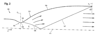
- Fig. 2 shows such a design of an ideal rotationally symmetrical nozzle 100, through which a flow passes in the direction of the arrow P from the convergent nozzle section through the throat section to the divergent nozzle section.
- a circular arc 104 with a predetermined radius is assumed as default.
- the predetermined radius can also have the value 0, wherein the wall of the convergent section then passes, forming a point of discontinuity creating the throat, directly into the wall of the divergent section.
- expansion waves run towards the nozzle longitudinal axis 101, at which they are reflected.
- the section 108 of the wall 103 downstream of the last point 105 of the circular arc 104 is curved in such a way towards the nozzle longitudinal axis 101 that the expansion waves reflected by the nozzle longitudinal axis and arriving at the wall 103 are immediately cancelled by the compressing wall contour in the section 108.
- a parallel flow prevails, and the flow corresponds to the design state.
- this last expansion wave reflection-propagation line 107 is also termed "design characteristic".
- the outlet plane E 2 lies in the cross section of the nozzle.
- the overall nozzle contour is already determined by the choice of the divergence angle (tangential angle on the circular arc 104) in the end point 105 of the circular arc 104.
- the ideal contour At a predetermined state in the combustion chamber, there is precisely one contour that can deflect the kernel flow determined by this end point 105 into a parallel flow, namely the ideal contour. If a chosen wall contour is less curved than the related ideal, expansion waves are reflected by the wall 103 into the flow field. However, if it is more strongly curved, compression waves run from the wall 103 into the flow field.
- the object of the present invention is to configure a generic thrust nozzle in such a way that the aforesaid design criteria are fulfilled, namely that while minimising the risk of stationary flow separation and the occurrence of lateral forces associated with this, as well as minimising the unavoidable lateral forces on start-up (suppression of the separation with reattachment), a maximum specific vacuum impulse, thus a maximum thrust, can be achieved, in particular even in stationary operation.
- the thrust nozzle according to the invention which can be provided in particular as a thrust nozzle for a rocket engine, is provided with a convergent wall section, a throat section and a divergent wall section, wherein the divergent wall section has a first region adjacent to the throat section, the wall contour of which corresponds to the wall contour of a truncated ideal nozzle, and wherein the divergent wall section has a second region facing away from the throat section, which region has a wall contour deviating from the first region.
- the wall contour of this second region is thus not a wall contour of an ideal TIC nozzle, but a wall contour deviating from this.
- the combination according to the invention of the first region of the divergent wall section, which region is adjacent to the throat of the thrust nozzle and corresponds to the wall contour of a truncated ideal nozzle, with a connecting section downstream with a deviating wall contour ensures on the one hand that, in the critical first region at the widening of the nozzle cross section, the occurrence of shocks and thus the hazardous separation with reattachment on account of particularly high lateral forces are suppressed due to the TIC nozzle contour there and that downstream of this, in the second region, if only a relatively small enlargement of the nozzle cross section occurs, the nozzle contour can be designed in such a way that the outlet pressure is sufficiently high to prevent flow separation in stationary operation.
- the contour angle of the divergent wall section, seen in longitudinal section through the thrust nozzle preferably runs continuously on the transition from the first region to the second region.
- the contour angle is defined by a tangential angle to the wall of the thrust nozzle.
- a first derivative of a curve describing the wall contour of the thrust nozzle along a length, i.e. along a longitudinal axis of the nozzle describes the development of the contour angle or tangential angle along the length, i.e. along the longitudinal axis of the nozzle.
- a curvature of the curve describing the wall contour of the thrust nozzle along its length is described by the second derivative of said curve.
- the first derivative of the curve describing the wall contour of the thrust nozzle preferably is continuous at a transition point between the first region and the second region.
- a second derivative of the curve describing the wall contour of the thrust nozzle may comprise a kink.
- a variant of the thrust nozzle is particularly preferred in which the second region of the divergent wall section is paraboloid-shaped.
- This paraboloid-shaped configuration corresponds to the contour of a thrust-optimised parabola.
- the transition from the wall contour of the first region to the wall contour of the second region is continuous, i.e. the development of the first derivative of the curve describing the wall contour of the thrust nozzle is continuous.
- the contour angle ⁇ corresponding to a tangential angle to the wall, at the last point of the wall contour of the first region hence may correspond to the contour angle ⁇ at the first point of the wall contour of the second region.
- a preferred use of the thrust nozzle according to the invention is realised in a rocket engine, so that the invention also comprises a rocket engine with a thrust nozzle according to the invention.
- a thrust nozzle S according to the invention is shown in longitudinal section in fig. 1 , wherein the nozzle wall is drawn only as a contour line and permits no conclusion as to the design configuration of the nozzle wall (material construction, cooling ducts etc.).
- the construction of nozzle walls, especially of rocket thrust nozzles, is sufficiently known and is not an object of the present invention.
- the nozzle has a convergent wall section 1, a throat section 2 and a divergent wall section 3.
- the narrowest cross section of the nozzle is located in the throat section 2 in the cross-sectional plane E 1 at the narrowest diameter of the throat section 2.
- the passage of flow through the nozzle is in the direction of the flow arrow P from the nozzle section with the convergent wall section 1 through the nozzle throat to the nozzle section with the divergent wall section 3.
- a combustion chamber situated ahead of the nozzle section with the convergent wall section 1 in a rocket engine is not shown in fig. 1 , but is sufficiently known to the person skilled in the art.
- the wall contour 20 in the throat section 2 is executed as a circular arc.
- a first region 30 of the divergent wall section 3 Connected to this circular arc of the wall contour 20 of the throat section 2 in a downstream direction, thus towards the divergent wall section 3, is a first region 30 of the divergent wall section 3, the wall contour 31 of which - as already described in connection with fig. 2 - is formed as a truncated ideal nozzle (TIC nozzle).
- TIC nozzle truncated ideal nozzle
- the transition from the circular-arc-shaped wall contour 20 of the throat section 2 to the wall contour 31 of the first region 30 formed as a truncated TIC nozzle is defined by a first transition point 34, through which a first transition cross-sectional plane E 3 runs.
- the first region 30 with the contour of a truncated ideal nozzle extends in the direction of the nozzle longitudinal axis 101, but not over the full length of a TIC nozzle as shown in fig. 2 and described in connection with fig. 2 , but only over a portion of the length of an ideal nozzle close to the throat.
- the axial length L 1 of the first region 30 is determined according to a design specification, which is described further below.
- the transition between the wall contour 31 of the first region 30 and the wall contour 33 of the second region 32 of the divergent wall section 3 is realised at a second transition point 35, through which a second transition cross-sectional plane E 4 runs.
- the transition from the wall contour 31 of the first region 30 to the wall contour 33 of the second region 32 is continuous.
- the contour angle ⁇ that is the tangential angle (in the longitudinal sectional plane shown in fig. 1 ) to the wall at the last point of the wall contour 31 of the first region corresponds to the contour angle ⁇ at the first point of the wall contour 33 of the second region 32, as is to be seen in the enlarged representation in fig. 1A .
- the wall contour 33 of the second region 32 is formed as a quadratic parabola.
- This second region 32 configured in a paraboloid shape of the divergent wall section 3 extends in the direction of the nozzle longitudinal axis 101 over a length L 2 as far as the outlet plane E 2 .
- the position of this outlet plane E 2 is determined by the predetermined overall length L of the nozzle, measured from the plane E 1 to the plane E 2 .
- the nozzle throat cross section, the nozzle length and the nozzle outlet diameter are normally preset.
- the start and end point of the nozzle according to the invention are thus fixed.
- three parameters remain as free parameters in the design process, namely:
- the starting point (second transition point 35) and the starting angle (contour angle ⁇ ) of the paraboloid-shaped second region 32 of the divergent wall section 3 are determined here by the end point and the end angle of the truncated ideal nozzle, thus of the first region 30. This point is the second transition point 35. In principle it would also be possible to permit a small angle change outwards at the second transition point 35. This would add another degree of freedom for the design. However, the further the nozzle is opened at the second transition point 35, thus the greater the change in the contour angle ⁇ at this point, the greater the risk that a shock is induced in the further progression of the paraboloid-shaped second region 32 that would nullify the advantages of the contouring method described.
- the end point of the paraboloid-shaped second region 32 is normally predetermined in the design process on account of the predetermined nozzle length L and the predetermined opening cross section of the nozzle in the outlet plane E 2 .
- a wall contour of a truncated ideal nozzle should necessarily be chosen up to the first transition point 34, because only this guarantees shock-free operation.
- a wall contour Downstream of the second transition point 35, a wall contour must be selected which contains the three fixed design parameters, namely the starting point, the starting angle and the end point of the wall contour and in which the third free parameter (divergence angle ⁇ ) can be varied. This doesn't necessarily have to be an oblique parabola of the second degree, but this is an obvious choice.
- the wall of the second region 32 could also be described by a higher-order curve when seen in cross section.
- the thrust nozzle according to the invention shown in fig. 1 thus combines the advantages of an ideal nozzle (TIC nozzle) with the advantages of a TOP nozzle with paraboloid wall contour and can therefore be described as a TICTOP nozzle.
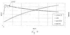
- Figs. 3 and 4 illustrate the contour of two examples of the combined TICTOP thrust nozzle according to the invention compared to the TOP thrust nozzle with the same exit point.
- the dashed lines correspond to the contour (31, 33) y as a function of the length-coordinate x of the respective thrust nozzle, while the solid lines correspond to the first derivative dy/dx of said curve.
- the transition between the TIC and the parabolic nozzle section can be identified in the first derivative, since the first derivative shows a kink at the transition point from the TIC to the parabolic nozzle section. This transition is surrounded by the circle 110.
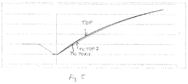
- Fig. 5 illustrates the contour of the TOP thrust nozzle in comparison with the two example of the TICTOP thrust nozzle of Figs. 3 and 4 .
- the TICTOP thrust nozzle is provided with a contour (31, 33) line in the transition region between the first and the second region (30, 32) that lies well below the contour line of the TOP thrust nozzle, while upstream and downstream of the transition point, the contour line (31, 33) of the TICTOP thrust nozzles converges against the contour line of the TOP thrust nozzle.
Landscapes
- Engineering & Computer Science (AREA)
- Chemical & Material Sciences (AREA)
- Combustion & Propulsion (AREA)
- Mechanical Engineering (AREA)
- General Engineering & Computer Science (AREA)
- Testing Of Engines (AREA)
- Nozzles (AREA)
- Jet Pumps And Other Pumps (AREA)
- Aerodynamic Tests, Hydrodynamic Tests, Wind Tunnels, And Water Tanks (AREA)
Abstract
Description
- The present invention relates to a thrust nozzle, in particular a thrust nozzle for a rocket engine, according to the preamble of
claim 1. - Thrust nozzles of rocket engines are formed as convergent-divergent expansion nozzles. These nozzles produce optimal thrust when the ambient pressure is of the same magnitude as the average pressure in the nozzle outlet plane. The flow is attached everywhere close to the nozzle wall and does not experience any change of direction at the nozzle outlet in the case of a uniform velocity distribution. If the nozzle outlet pressure is above the ambient pressure, then the gas exit velocity is lower than in the case of the nozzle flow adapted to the ambient pressure. If the nozzle outlet pressure is lower than the ambient pressure, on the other hand, then although the gas exit velocity is higher than in the case of the adjusted nozzle flow, the constriction of the exhaust gas jet that occurs can result in a flow separation. In this case, no separation occurs initially. Only when the pressure at the nozzle end falls to below 40% of the ambient pressure does separation occur. However, once it falls below the ambient pressure, the thrust is no longer optimal.
- Flow separations from the wall of the thrust nozzle should be avoided, however, as lateral forces occur that do not act in the desired thrust direction on the rocket engine and can lead to mechanical damage.
- The wall contour of the thrust nozzle exerts a substantial influence on the flow progression in the inside of the thrust nozzle and in particular in its divergent section.
- Two different contouring methods have basically existed up to now for thrust nozzles, namely a thrust-optimised parabola (TOP) and a so-called truncated ideal nozzle (Truncated Ideal Contour, TIC).
- Flow separation and lateral forces occur in principle on start-up of a nozzle, regardless of which type it is. The lateral forces in particular can be of different magnitude here depending on the contouring type (TIC or TOP). Normally the aim is to design nozzles in such a way that flow separation is prevented in stationary operation.
- Parabolic TOP nozzles generally attain a high nozzle outlet pressure and if necessary, the nozzle outlet pressure can be increased further by reducing the outlet angle, which is a basic design criterion for avoiding flow separations. At the same time, however, a TOP nozzle produces an internal shock, which can produce a flow separation with subsequent reattachment of the flow to the wall. Especially high lateral forces are generated by this, which can be hazardous for the operation of the rocket engine.
- The truncated ideal nozzle (TIC nozzle), on the other hand, is shock-free and prevents the undesirable separation of the flow caused by the particularly high lateral forces arising with subsequent reattachment to the wall. On start-up of a TIC nozzle, only moderate lateral forces therefore occur. However, with the same length of the divergent section of a thrust nozzle and same radius of the end point, a much lower nozzle pressure results with a TIC nozzle than with a TOP nozzle, which leads to the possibility of flow separations occurring in stationary operation with the TIC nozzle.
- When designing the nozzle contour of a rocket engine launched on the ground, thus for the rocket engines of the first rocket stage, the unavoidable lateral forces during the start-up should be kept as small as possible, which can be achieved by suppressing the internal shock, so that a flow separation with reattachment is prevented.
- A flow separation in stationary operation, meaning on reaching full combustion chamber pressure, should be avoided and in addition the highest possible specific vacuum impulse should be aimed for in stationary operation. Nozzles currently in existence, thus both TOP nozzles and TIC nozzles, cannot fulfil these design criteria simultaneously.
- While the wall contour of parabolic TOP nozzles has the form of a quadratic parabola or a higher-order parabola in longitudinal section, the contour of ideal nozzles (TIC nozzles) cannot be described by simple mathematical functions. A design specification for an ideal TIC nozzle has been previously published in: Frey, Manuel, "Behandlung von Strömungsproblemen in Raketendüsen bei Überexpansion" (Dealing with Flow Problems in Rocket Nozzles in the Event of Overexpansion), dissertation, University of Stuttgart, 2001, pages 22 to 27. According to the design specification for ideal nozzles (TIC nozzles) provided there, ideal nozzles are designed using the method of characteristics.
-
Fig. 2 shows such a design of an ideal rotationallysymmetrical nozzle 100, through which a flow passes in the direction of the arrow P from the convergent nozzle section through the throat section to the divergent nozzle section. For the contour of thewall 103 at the narrowest point of thenozzle 100, thenozzle throat 102, acircular arc 104 with a predetermined radius is assumed as default. However, the predetermined radius can also have thevalue 0, wherein the wall of the convergent section then passes, forming a point of discontinuity creating the throat, directly into the wall of the divergent section. - From the
nozzle throat 102 of the example shown infig. 2 , expansion waves run towards the nozzlelongitudinal axis 101, at which they are reflected. The region K upstream of the so-called characteristic last expansionwave propagation line 106, which proceeds from thelast point 105 of thecircular arc 104 situated in the divergent nozzle section, is termed "kernel". Expansion waves occur in this kernel region. Infig. 2 this is the region between the cross-sectional plane E1 at the narrowest throat diameter and the last expansionwave propagation line 106. - The
section 108 of thewall 103 downstream of thelast point 105 of thecircular arc 104 is curved in such a way towards the nozzlelongitudinal axis 101 that the expansion waves reflected by the nozzle longitudinal axis and arriving at thewall 103 are immediately cancelled by the compressing wall contour in thesection 108. As a consequence, downstream of the last expansion wave reflection-propagation line 107 of the last expansion wave reflected by the nozzlelongitudinal axis 101, a parallel flow prevails, and the flow corresponds to the design state. For this reason this last expansion wave reflection-propagation line 107 is also termed "design characteristic". At thewall end point 109 where this last expansion wave reflection-propagation line 107 encounters thewall 103, the outlet plane E2 lies in the cross section of the nozzle. - The overall nozzle contour is already determined by the choice of the divergence angle (tangential angle on the circular arc 104) in the
end point 105 of thecircular arc 104. At a predetermined state in the combustion chamber, there is precisely one contour that can deflect the kernel flow determined by thisend point 105 into a parallel flow, namely the ideal contour. If a chosen wall contour is less curved than the related ideal, expansion waves are reflected by thewall 103 into the flow field. However, if it is more strongly curved, compression waves run from thewall 103 into the flow field. - The object of the present invention, therefore, is to configure a generic thrust nozzle in such a way that the aforesaid design criteria are fulfilled, namely that while minimising the risk of stationary flow separation and the occurrence of lateral forces associated with this, as well as minimising the unavoidable lateral forces on start-up (suppression of the separation with reattachment), a maximum specific vacuum impulse, thus a maximum thrust, can be achieved, in particular even in stationary operation.
- This object is achieved by the thrust nozzle with the features of
claim 1. - The thrust nozzle according to the invention, which can be provided in particular as a thrust nozzle for a rocket engine, is provided with a convergent wall section, a throat section and a divergent wall section, wherein the divergent wall section has a first region adjacent to the throat section, the wall contour of which corresponds to the wall contour of a truncated ideal nozzle, and wherein the divergent wall section has a second region facing away from the throat section, which region has a wall contour deviating from the first region. The wall contour of this second region is thus not a wall contour of an ideal TIC nozzle, but a wall contour deviating from this.
- The combination according to the invention of the first region of the divergent wall section, which region is adjacent to the throat of the thrust nozzle and corresponds to the wall contour of a truncated ideal nozzle, with a connecting section downstream with a deviating wall contour ensures on the one hand that, in the critical first region at the widening of the nozzle cross section, the occurrence of shocks and thus the hazardous separation with reattachment on account of particularly high lateral forces are suppressed due to the TIC nozzle contour there and that downstream of this, in the second region, if only a relatively small enlargement of the nozzle cross section occurs, the nozzle contour can be designed in such a way that the outlet pressure is sufficiently high to prevent flow separation in stationary operation.
- Other preferred and advantageous configuration features of the thrust nozzle according to the invention are the subject matter of
subordinate claims 2 to 4. - The contour angle of the divergent wall section, seen in longitudinal section through the thrust nozzle, preferably runs continuously on the transition from the first region to the second region. The contour angle is defined by a tangential angle to the wall of the thrust nozzle. Hence, a first derivative of a curve describing the wall contour of the thrust nozzle along a length, i.e. along a longitudinal axis of the nozzle, describes the development of the contour angle or tangential angle along the length, i.e. along the longitudinal axis of the nozzle. A curvature of the curve describing the wall contour of the thrust nozzle along its length is described by the second derivative of said curve. The first derivative of the curve describing the wall contour of the thrust nozzle preferably is continuous at a transition point between the first region and the second region. A second derivative of the curve describing the wall contour of the thrust nozzle, however, may comprise a kink. The steady transition between the two regions of the divergent wall section reduces the risk of the occurrence of internal pressure shocks and a flow separation associated with this.
- A variant of the thrust nozzle is particularly preferred in which the second region of the divergent wall section is paraboloid-shaped. This paraboloid-shaped configuration corresponds to the contour of a thrust-optimised parabola. Such a thrust nozzle thus combines in the first region close to the throat the properties of a TIC nozzle with the properties of a TOP nozzle in the second region downstream.
- As already indicated above, according to a preferred embodiment of the trust nozzle, the transition from the wall contour of the first region to the wall contour of the second region is continuous, i.e. the development of the first derivative of the curve describing the wall contour of the thrust nozzle is continuous. The contour angle α corresponding to a tangential angle to the wall, at the last point of the wall contour of the first region, hence may correspond to the contour angle α at the first point of the wall contour of the second region. By choosing the transition between the first and the second region as being continuous and having the same contour angle α in the last point of the first region and in the first point of the second region, the truncated ideal nozzle (TIC) and the thrust-optimised nozzle (TOP) can be combined in an advantageous manner. The combination of both nozzle contours improves the functioning of the thrust nozzle.
- A preferred use of the thrust nozzle according to the invention is realised in a rocket engine, so that the invention also comprises a rocket engine with a thrust nozzle according to the invention.
- Preferred practical examples of the invention with additional configuration details and other advantages are described and explained in greater detail below with reference to the enclosed drawings.
- The figures show:
- Fig. 1
- a thrust nozzle according to the invention;
- Fig. 1A
- the section A from
fig. 1 ; - Fig. 2
- a previously known ideal nozzle;
- Figs. 3
- the contour of a first examplary thrust nozzle according to the invention in comparison with a TOP thrust nozzle;
- Figs. 4
- the contour of a second examplary thrust nozzle according to the invention in comparison with a TOP thrust nozzle; and
- Fig. 5
- the contour of the two exemplary thrust nozzles according to the invention as shown in
Figs. 3 and4 in comparison with a TOP thrust nozzle. - A thrust nozzle S according to the invention is shown in longitudinal section in
fig. 1 , wherein the nozzle wall is drawn only as a contour line and permits no conclusion as to the design configuration of the nozzle wall (material construction, cooling ducts etc.). The construction of nozzle walls, especially of rocket thrust nozzles, is sufficiently known and is not an object of the present invention. - The nozzle has a
convergent wall section 1, athroat section 2 and adivergent wall section 3. The narrowest cross section of the nozzle is located in thethroat section 2 in the cross-sectional plane E1 at the narrowest diameter of thethroat section 2. The passage of flow through the nozzle is in the direction of the flow arrow P from the nozzle section with theconvergent wall section 1 through the nozzle throat to the nozzle section with thedivergent wall section 3. A combustion chamber situated ahead of the nozzle section with theconvergent wall section 1 in a rocket engine is not shown infig. 1 , but is sufficiently known to the person skilled in the art. - As already described in connection with the prior art in
fig. 2 , the wall contour 20 in thethroat section 2 is executed as a circular arc. Connected to this circular arc of the wall contour 20 of thethroat section 2 in a downstream direction, thus towards thedivergent wall section 3, is afirst region 30 of thedivergent wall section 3, thewall contour 31 of which - as already described in connection withfig. 2 - is formed as a truncated ideal nozzle (TIC nozzle). The transition from the circular-arc-shaped wall contour 20 of thethroat section 2 to thewall contour 31 of thefirst region 30 formed as a truncated TIC nozzle is defined by a first transition point 34, through which a first transition cross-sectional plane E3 runs. - The transition from the circular-arc-shaped wall contour 20 of the
throat section 2 to thewall contour 31 of thefirst region 30 is realised continuously; this means that the tangential angle (in the longitudinal sectional plane shown infig. 1 ) at the last point of the circular-arc-shaped wall contour 20 of thethroat section 2 corresponds to the tangential angle at the first point of thewall contour 31 of thefirst region 30. - The
first region 30 with the contour of a truncated ideal nozzle extends in the direction of the nozzlelongitudinal axis 101, but not over the full length of a TIC nozzle as shown infig. 2 and described in connection withfig. 2 , but only over a portion of the length of an ideal nozzle close to the throat. The axial length L1 of thefirst region 30 is determined according to a design specification, which is described further below. - Adjoining the
first region 30 of thedivergent wall section 3 at the end of thefirst region 30 facing away from thethroat section 2 is asecond region 32 of thedivergent wall section 3, which has awall contour 33 deviating from thefirst region 30 and thus also from an ideal TIC nozzle. The transition between thewall contour 31 of thefirst region 30 and thewall contour 33 of thesecond region 32 of thedivergent wall section 3 is realised at asecond transition point 35, through which a second transition cross-sectional plane E4 runs. - The transition from the
wall contour 31 of thefirst region 30 to thewall contour 33 of thesecond region 32 is continuous. This means that the contour angle α, that is the tangential angle (in the longitudinal sectional plane shown infig. 1 ) to the wall at the last point of thewall contour 31 of the first region corresponds to the contour angle α at the first point of thewall contour 33 of thesecond region 32, as is to be seen in the enlarged representation infig. 1A . - In the example of
fig. 1 , thewall contour 33 of thesecond region 32 is formed as a quadratic parabola. Thissecond region 32 configured in a paraboloid shape of thedivergent wall section 3 extends in the direction of the nozzlelongitudinal axis 101 over a length L2 as far as the outlet plane E2. The position of this outlet plane E2 is determined by the predetermined overall length L of the nozzle, measured from the plane E1 to the plane E2. - The design of such a combined TICTOP thrust nozzle according to the invention and in particular the determination of the
second transition point 35 with the second transition cross-sectional plane E4 is described below. - In the design process of a thrust nozzle, the nozzle throat cross section, the nozzle length and the nozzle outlet diameter are normally preset. The start and end point of the nozzle according to the invention are thus fixed. Thus three parameters remain as free parameters in the design process, namely:
- 1. The first free parameter is the design Mach number of the ideal nozzle. The greater the design Mach number, the more divergent (at the same axial length L1) is the
first region 30 formed as a truncated ideal nozzle, i.e. the greater the divergence angle at the first transition point 34 between the circular-arc-shaped wall contour 20 of thethroat section 2 and thewall contour 31 of thefirst region 30, thus the truncated ideal nozzle. Due to this the greater the contour angle α is also at thesecond transition point 35 between thewall contour 31 of thefirst region 30 and thewall contour 33 of the paraboloid-shapedsecond region 32 of thedivergent wall section 3. - 2. The second free parameter is the axial length L1 of the thrust nozzle S in the
first region 30, thus of the truncated ideal nozzle used, and thus the axial position of thesecond transition point 35. - 3. The third free parameter is the divergence angle β of the paraboloid-shaped
wall contour 33 of thesecond region 32 at the open outlet end of the thrust nozzle, thus in the area of the outlet plane E2. The nozzle end pressure can be varied by this value. The smaller the divergence angle β is at a constant nozzle length L, the higher the nozzle end pressure. - The starting point (second transition point 35) and the starting angle (contour angle α) of the paraboloid-shaped
second region 32 of thedivergent wall section 3 are determined here by the end point and the end angle of the truncated ideal nozzle, thus of thefirst region 30. This point is thesecond transition point 35. In principle it would also be possible to permit a small angle change outwards at thesecond transition point 35. This would add another degree of freedom for the design. However, the further the nozzle is opened at thesecond transition point 35, thus the greater the change in the contour angle α at this point, the greater the risk that a shock is induced in the further progression of the paraboloid-shapedsecond region 32 that would nullify the advantages of the contouring method described. - The end point of the paraboloid-shaped
second region 32 is normally predetermined in the design process on account of the predetermined nozzle length L and the predetermined opening cross section of the nozzle in the outlet plane E2. - Upstream of the
second transition point 35, a wall contour of a truncated ideal nozzle should necessarily be chosen up to the first transition point 34, because only this guarantees shock-free operation. Downstream of thesecond transition point 35, a wall contour must be selected which contains the three fixed design parameters, namely the starting point, the starting angle and the end point of the wall contour and in which the third free parameter (divergence angle β) can be varied. This doesn't necessarily have to be an oblique parabola of the second degree, but this is an obvious choice. Alternatively, the wall of thesecond region 32 could also be described by a higher-order curve when seen in cross section. - The thrust nozzle according to the invention shown in
fig. 1 thus combines the advantages of an ideal nozzle (TIC nozzle) with the advantages of a TOP nozzle with paraboloid wall contour and can therefore be described as a TICTOP nozzle. -
Figs. 3 and4 illustrate the contour of two examples of the combined TICTOP thrust nozzle according to the invention compared to the TOP thrust nozzle with the same exit point. The dashed lines correspond to the contour (31, 33) y as a function of the length-coordinate x of the respective thrust nozzle, while the solid lines correspond to the first derivative dy/dx of said curve. The transition between the TIC and the parabolic nozzle section can be identified in the first derivative, since the first derivative shows a kink at the transition point from the TIC to the parabolic nozzle section. This transition is surrounded by thecircle 110. -
Fig. 5 illustrates the contour of the TOP thrust nozzle in comparison with the two example of the TICTOP thrust nozzle ofFigs. 3 and4 . As becomes apparent fromfigs. 3 to 5 , the TICTOP thrust nozzle is provided with a contour (31, 33) line in the transition region between the first and the second region (30, 32) that lies well below the contour line of the TOP thrust nozzle, while upstream and downstream of the transition point, the contour line (31, 33) of the TICTOP thrust nozzles converges against the contour line of the TOP thrust nozzle. - Reference signs in the claims, the description and the drawings serve only for a better understanding of the invention and are not intended to limit the protective scope.
-
- 1
- Convergent wall section
- 2
- Throat section
- 3
- Divergent wall section
- 20
- Wall contour of the throat section
- 30
- First region
- 31
- Wall contour of the first region
- 32
- Second region
- 33
- Wall contour of the second region
- 34
- First transition point
- 35
- Second transition point
- 100
- Rotationally symmetrical nozzle
- 101
- Nozzle longitudinal axis
- 102
- Nozzle throat
- 103
- Wall
- 104
- Circular arc
- 105
- Point
- 106
- Expansion wave propagation line
- 107
- Expansion wave reflection propagation line
- 108
- Section of the wall contour
- 109
- Wall end point
- 110
- Circle indication the transition from TIC to TOP
- α
- Contour angle
- β
- Divergence angle
- E1
- Cross-sectional plane at the narrowest throat diameter
- E2
- Outlet plane
- E3
- Transition cross-sectional plane
- E4
- Second transition cross-sectional plane
- K
- "Kernel" region
- L
- Overall length of nozzle
- L1
- Axial length of the first region
- L2
- Axial length of the second region
- P
- Flow arrow
- S
- Thrust nozzle
Claims (5)
- Thrust nozzle, in particular thrust nozzle for a rocket engine, with a convergent wall section (1), a throat section (2) and a divergent wall section (3), characterised in that- the divergent wall section (3) has a first region (30) adjacent to the throat section (2), the wall contour (31) of which region corresponds to a truncated ideal nozzle, and- the divergent wall section (3) has a second region (32) facing away from the throat section (2), which region has a wall contour (33) deviating from the first region (30).
- Thrust nozzle according to claim 1, characterised in that a contour angle (α) of the divergent wall section (3), seen in longitudinal section through the thrust nozzle (S), runs continuously on the transition from the first region (30) to the second region (32).
- Thrust nozzle according to claim 1 or 2, characterised in that the second region (32) of the divergent wall section (3) is paraboloid-shaped.
- Thrust nozzle according to one of the preceding claims, characterised in that the transition from the wall contour (31) of the first region (30) to the wall contour (33) of the second region (32) is continuous, wherein the contour angle (α) corresponding to a tangential angle to the wall, at the last point of the wall contour (31) of the first region, corresponds to the contour angle (α) at the first point of the wall contour (33) of the second region (32).
- Rocket engine with a thrust nozzle according to one of the preceding claims.
Applications Claiming Priority (1)
| Application Number | Priority Date | Filing Date | Title |
|---|---|---|---|
| DE102015011958.3A DE102015011958B4 (en) | 2015-09-18 | 2015-09-18 | Thruster |
Publications (2)
| Publication Number | Publication Date |
|---|---|
| EP3144517A1 true EP3144517A1 (en) | 2017-03-22 |
| EP3144517B1 EP3144517B1 (en) | 2020-05-27 |
Family
ID=56939973
Family Applications (1)
| Application Number | Title | Priority Date | Filing Date |
|---|---|---|---|
| EP16189329.2A Active EP3144517B1 (en) | 2015-09-18 | 2016-09-16 | Thrust nozzle |
Country Status (5)
| Country | Link |
|---|---|
| US (1) | US10590888B2 (en) |
| EP (1) | EP3144517B1 (en) |
| JP (1) | JP6342965B2 (en) |
| DE (1) | DE102015011958B4 (en) |
| ES (1) | ES2805532T3 (en) |
Cited By (1)
| Publication number | Priority date | Publication date | Assignee | Title |
|---|---|---|---|---|
| CN109595124A (en) * | 2018-10-31 | 2019-04-09 | 华中科技大学 | A kind of dislocation negative pressure suction type wind-gathering device |
Families Citing this family (3)
| Publication number | Priority date | Publication date | Assignee | Title |
|---|---|---|---|---|
| US20200049103A1 (en) * | 2018-06-29 | 2020-02-13 | Christopher Craddock | Aerospike Rocket Engine |
| DE102019109195A1 (en) * | 2019-04-08 | 2020-10-08 | Norma Germany Gmbh | Jet pump |
| CN115875160B (en) * | 2022-12-19 | 2026-02-24 | 北京中科宇航技术有限公司 | Single-chamber double-thrust solid engine and jet pipe thereof |
Citations (2)
| Publication number | Priority date | Publication date | Assignee | Title |
|---|---|---|---|---|
| WO1998012429A1 (en) * | 1996-09-23 | 1998-03-26 | Volvo Aero Corporation | Controlled temperature rocket nozzle |
| WO2000034641A1 (en) * | 1998-12-04 | 2000-06-15 | Volvo Aero Corporation | Rocket nozzle contour for flow separation control and side load reduction |
Family Cites Families (2)
| Publication number | Priority date | Publication date | Assignee | Title |
|---|---|---|---|---|
| US7051513B2 (en) * | 2003-06-06 | 2006-05-30 | United Technologies Corporation | Rocket engine tubular chamber with single piece jacket |
| US8453997B2 (en) * | 2010-11-20 | 2013-06-04 | Fisonic Holding Limited | Supersonic nozzle |
-
2015
- 2015-09-18 DE DE102015011958.3A patent/DE102015011958B4/en active Active
-
2016
- 2016-09-16 ES ES16189329T patent/ES2805532T3/en active Active
- 2016-09-16 EP EP16189329.2A patent/EP3144517B1/en active Active
- 2016-09-19 US US15/268,737 patent/US10590888B2/en active Active
- 2016-09-20 JP JP2016182888A patent/JP6342965B2/en active Active
Patent Citations (2)
| Publication number | Priority date | Publication date | Assignee | Title |
|---|---|---|---|---|
| WO1998012429A1 (en) * | 1996-09-23 | 1998-03-26 | Volvo Aero Corporation | Controlled temperature rocket nozzle |
| WO2000034641A1 (en) * | 1998-12-04 | 2000-06-15 | Volvo Aero Corporation | Rocket nozzle contour for flow separation control and side load reduction |
Non-Patent Citations (2)
| Title |
|---|
| CHLOE GENIN ET AL: "Hot Flow Testing of Dual Bell Nozzles", 49TH AIAA AEROSPACE SCIENCES MEETING INCLUDING THE NEW HORIZONS FORUM AND AEROSPACE EXPOSITION, 4 January 2011 (2011-01-04), Reston, Virigina, XP055341544, ISBN: 978-1-60086-950-1, DOI: 10.2514/6.2011-387 * |
| FREY, MANUEL: "Behand-lung von Stromungsproblemen in Raketendusen bei Uberexpansion", DISSERTATION, 2001, pages 22 - 27 |
Cited By (1)
| Publication number | Priority date | Publication date | Assignee | Title |
|---|---|---|---|---|
| CN109595124A (en) * | 2018-10-31 | 2019-04-09 | 华中科技大学 | A kind of dislocation negative pressure suction type wind-gathering device |
Also Published As
| Publication number | Publication date |
|---|---|
| US20170122260A1 (en) | 2017-05-04 |
| US10590888B2 (en) | 2020-03-17 |
| JP2017078405A (en) | 2017-04-27 |
| JP6342965B2 (en) | 2018-06-13 |
| EP3144517B1 (en) | 2020-05-27 |
| ES2805532T3 (en) | 2021-02-12 |
| DE102015011958A1 (en) | 2017-03-23 |
| DE102015011958B4 (en) | 2024-02-01 |
Similar Documents
| Publication | Publication Date | Title |
|---|---|---|
| US10590888B2 (en) | Thrust nozzle with double contour and smooth transition | |
| US11066993B2 (en) | Variable geometry inlet system | |
| EP1340901B1 (en) | Noise attenuating segmented exhaust nozzle | |
| US7334395B2 (en) | Aircraft structure that includes a duct for guiding fluid flow therethrough | |
| KR100254284B1 (en) | Turbine nozzles and turbine rotor blades of axial flow turbine | |
| WO2001019675A2 (en) | Supersonic external-compression diffuser and method for designing same | |
| US20060005530A1 (en) | Thrust reverser comprising optimised deflector gratings | |
| US11047303B2 (en) | Supply duct of a compressor of a turbine engine | |
| NL8003399A (en) | DIFFUSOR, FOR EXAMPLE FOR A GAS TURBINE. | |
| EP3508685A1 (en) | Turbine wheel, turbine, and turbocharger | |
| JPWO2020012648A1 (en) | Centrifugal compressor and turbocharger | |
| CN113646520B (en) | Non-axisymmetric secondary pipe section | |
| US8959924B2 (en) | Aircraft turbofan engine | |
| EP2744999B1 (en) | Nozzle arrangement and method of making the same | |
| US10036349B2 (en) | Afterbody for a turbojet engine comprising a nozzle provided with a thrust reverser system that incorporates a crown of noise-reducing chevrons | |
| US3038304A (en) | Variable exhaust nozzle configuration | |
| EP3260694A1 (en) | Gas turbine exhaust cooling system | |
| RU2761285C2 (en) | Inner case of intermediate case containing channels for direction of bypassed flow formed by output ribs | |
| RU2767862C2 (en) | Modified sound secondary nozzle | |
| EP2998556A1 (en) | Variable nozzle for aircraft gas turbine engine | |
| US12416256B2 (en) | Manifold, a turbomachine including such a manifold, a turbocharger including such a turbomachine, and an internal combustion engine including such a manifold | |
| EP3569853B1 (en) | Thrust reverser with continuous curved surface | |
| RU2367798C2 (en) | Turbojet engine | |
| CN116615375A (en) | Nacelle air scoop for an aircraft propulsion assembly for facilitating thrust reversal phases |
Legal Events
| Date | Code | Title | Description |
|---|---|---|---|
| PUAI | Public reference made under article 153(3) epc to a published international application that has entered the european phase |
Free format text: ORIGINAL CODE: 0009012 |
|
| STAA | Information on the status of an ep patent application or granted ep patent |
Free format text: STATUS: REQUEST FOR EXAMINATION WAS MADE |
|
| 17P | Request for examination filed |
Effective date: 20160916 |
|
| AK | Designated contracting states |
Kind code of ref document: A1 Designated state(s): AL AT BE BG CH CY CZ DE DK EE ES FI FR GB GR HR HU IE IS IT LI LT LU LV MC MK MT NL NO PL PT RO RS SE SI SK SM TR |
|
| AX | Request for extension of the european patent |
Extension state: BA ME |
|
| RAP1 | Party data changed (applicant data changed or rights of an application transferred) |
Owner name: ARIANEGROUP GMBH |
|
| STAA | Information on the status of an ep patent application or granted ep patent |
Free format text: STATUS: EXAMINATION IS IN PROGRESS |
|
| 17Q | First examination report despatched |
Effective date: 20180403 |
|
| GRAP | Despatch of communication of intention to grant a patent |
Free format text: ORIGINAL CODE: EPIDOSNIGR1 |
|
| STAA | Information on the status of an ep patent application or granted ep patent |
Free format text: STATUS: GRANT OF PATENT IS INTENDED |
|
| INTG | Intention to grant announced |
Effective date: 20200128 |
|
| GRAJ | Information related to disapproval of communication of intention to grant by the applicant or resumption of examination proceedings by the epo deleted |
Free format text: ORIGINAL CODE: EPIDOSDIGR1 |
|
| STAA | Information on the status of an ep patent application or granted ep patent |
Free format text: STATUS: EXAMINATION IS IN PROGRESS |
|
| GRAR | Information related to intention to grant a patent recorded |
Free format text: ORIGINAL CODE: EPIDOSNIGR71 |
|
| GRAS | Grant fee paid |
Free format text: ORIGINAL CODE: EPIDOSNIGR3 |
|
| STAA | Information on the status of an ep patent application or granted ep patent |
Free format text: STATUS: GRANT OF PATENT IS INTENDED |
|
| GRAA | (expected) grant |
Free format text: ORIGINAL CODE: 0009210 |
|
| STAA | Information on the status of an ep patent application or granted ep patent |
Free format text: STATUS: THE PATENT HAS BEEN GRANTED |
|
| INTC | Intention to grant announced (deleted) | ||
| AK | Designated contracting states |
Kind code of ref document: B1 Designated state(s): AL AT BE BG CH CY CZ DE DK EE ES FI FR GB GR HR HU IE IS IT LI LT LU LV MC MK MT NL NO PL PT RO RS SE SI SK SM TR |
|
| INTG | Intention to grant announced |
Effective date: 20200420 |
|
| REG | Reference to a national code |
Ref country code: GB Ref legal event code: FG4D |
|
| REG | Reference to a national code |
Ref country code: CH Ref legal event code: EP |
|
| REG | Reference to a national code |
Ref country code: AT Ref legal event code: REF Ref document number: 1274798 Country of ref document: AT Kind code of ref document: T Effective date: 20200615 |
|
| REG | Reference to a national code |
Ref country code: DE Ref legal event code: R096 Ref document number: 602016036943 Country of ref document: DE |
|
| REG | Reference to a national code |
Ref country code: SE Ref legal event code: TRGR |
|
| REG | Reference to a national code |
Ref country code: LT Ref legal event code: MG4D |
|
| PG25 | Lapsed in a contracting state [announced via postgrant information from national office to epo] |
Ref country code: LT Free format text: LAPSE BECAUSE OF FAILURE TO SUBMIT A TRANSLATION OF THE DESCRIPTION OR TO PAY THE FEE WITHIN THE PRESCRIBED TIME-LIMIT Effective date: 20200527 Ref country code: GR Free format text: LAPSE BECAUSE OF FAILURE TO SUBMIT A TRANSLATION OF THE DESCRIPTION OR TO PAY THE FEE WITHIN THE PRESCRIBED TIME-LIMIT Effective date: 20200828 Ref country code: NO Free format text: LAPSE BECAUSE OF FAILURE TO SUBMIT A TRANSLATION OF THE DESCRIPTION OR TO PAY THE FEE WITHIN THE PRESCRIBED TIME-LIMIT Effective date: 20200827 Ref country code: FI Free format text: LAPSE BECAUSE OF FAILURE TO SUBMIT A TRANSLATION OF THE DESCRIPTION OR TO PAY THE FEE WITHIN THE PRESCRIBED TIME-LIMIT Effective date: 20200527 Ref country code: IS Free format text: LAPSE BECAUSE OF FAILURE TO SUBMIT A TRANSLATION OF THE DESCRIPTION OR TO PAY THE FEE WITHIN THE PRESCRIBED TIME-LIMIT Effective date: 20200927 Ref country code: PT Free format text: LAPSE BECAUSE OF FAILURE TO SUBMIT A TRANSLATION OF THE DESCRIPTION OR TO PAY THE FEE WITHIN THE PRESCRIBED TIME-LIMIT Effective date: 20200928 |
|
| REG | Reference to a national code |
Ref country code: NL Ref legal event code: MP Effective date: 20200527 |
|
| PG25 | Lapsed in a contracting state [announced via postgrant information from national office to epo] |
Ref country code: LV Free format text: LAPSE BECAUSE OF FAILURE TO SUBMIT A TRANSLATION OF THE DESCRIPTION OR TO PAY THE FEE WITHIN THE PRESCRIBED TIME-LIMIT Effective date: 20200527 Ref country code: HR Free format text: LAPSE BECAUSE OF FAILURE TO SUBMIT A TRANSLATION OF THE DESCRIPTION OR TO PAY THE FEE WITHIN THE PRESCRIBED TIME-LIMIT Effective date: 20200527 Ref country code: RS Free format text: LAPSE BECAUSE OF FAILURE TO SUBMIT A TRANSLATION OF THE DESCRIPTION OR TO PAY THE FEE WITHIN THE PRESCRIBED TIME-LIMIT Effective date: 20200527 Ref country code: BG Free format text: LAPSE BECAUSE OF FAILURE TO SUBMIT A TRANSLATION OF THE DESCRIPTION OR TO PAY THE FEE WITHIN THE PRESCRIBED TIME-LIMIT Effective date: 20200827 |
|
| REG | Reference to a national code |
Ref country code: AT Ref legal event code: MK05 Ref document number: 1274798 Country of ref document: AT Kind code of ref document: T Effective date: 20200527 |
|
| PG25 | Lapsed in a contracting state [announced via postgrant information from national office to epo] |
Ref country code: NL Free format text: LAPSE BECAUSE OF FAILURE TO SUBMIT A TRANSLATION OF THE DESCRIPTION OR TO PAY THE FEE WITHIN THE PRESCRIBED TIME-LIMIT Effective date: 20200527 Ref country code: AL Free format text: LAPSE BECAUSE OF FAILURE TO SUBMIT A TRANSLATION OF THE DESCRIPTION OR TO PAY THE FEE WITHIN THE PRESCRIBED TIME-LIMIT Effective date: 20200527 |
|
| PG25 | Lapsed in a contracting state [announced via postgrant information from national office to epo] |
Ref country code: RO Free format text: LAPSE BECAUSE OF FAILURE TO SUBMIT A TRANSLATION OF THE DESCRIPTION OR TO PAY THE FEE WITHIN THE PRESCRIBED TIME-LIMIT Effective date: 20200527 Ref country code: CZ Free format text: LAPSE BECAUSE OF FAILURE TO SUBMIT A TRANSLATION OF THE DESCRIPTION OR TO PAY THE FEE WITHIN THE PRESCRIBED TIME-LIMIT Effective date: 20200527 Ref country code: DK Free format text: LAPSE BECAUSE OF FAILURE TO SUBMIT A TRANSLATION OF THE DESCRIPTION OR TO PAY THE FEE WITHIN THE PRESCRIBED TIME-LIMIT Effective date: 20200527 Ref country code: EE Free format text: LAPSE BECAUSE OF FAILURE TO SUBMIT A TRANSLATION OF THE DESCRIPTION OR TO PAY THE FEE WITHIN THE PRESCRIBED TIME-LIMIT Effective date: 20200527 Ref country code: AT Free format text: LAPSE BECAUSE OF FAILURE TO SUBMIT A TRANSLATION OF THE DESCRIPTION OR TO PAY THE FEE WITHIN THE PRESCRIBED TIME-LIMIT Effective date: 20200527 Ref country code: SM Free format text: LAPSE BECAUSE OF FAILURE TO SUBMIT A TRANSLATION OF THE DESCRIPTION OR TO PAY THE FEE WITHIN THE PRESCRIBED TIME-LIMIT Effective date: 20200527 |
|
| REG | Reference to a national code |
Ref country code: ES Ref legal event code: FG2A Ref document number: 2805532 Country of ref document: ES Kind code of ref document: T3 Effective date: 20210212 |
|
| PG25 | Lapsed in a contracting state [announced via postgrant information from national office to epo] |
Ref country code: PL Free format text: LAPSE BECAUSE OF FAILURE TO SUBMIT A TRANSLATION OF THE DESCRIPTION OR TO PAY THE FEE WITHIN THE PRESCRIBED TIME-LIMIT Effective date: 20200527 Ref country code: SK Free format text: LAPSE BECAUSE OF FAILURE TO SUBMIT A TRANSLATION OF THE DESCRIPTION OR TO PAY THE FEE WITHIN THE PRESCRIBED TIME-LIMIT Effective date: 20200527 |
|
| REG | Reference to a national code |
Ref country code: DE Ref legal event code: R097 Ref document number: 602016036943 Country of ref document: DE |
|
| PLBE | No opposition filed within time limit |
Free format text: ORIGINAL CODE: 0009261 |
|
| STAA | Information on the status of an ep patent application or granted ep patent |
Free format text: STATUS: NO OPPOSITION FILED WITHIN TIME LIMIT |
|
| PG25 | Lapsed in a contracting state [announced via postgrant information from national office to epo] |
Ref country code: MC Free format text: LAPSE BECAUSE OF FAILURE TO SUBMIT A TRANSLATION OF THE DESCRIPTION OR TO PAY THE FEE WITHIN THE PRESCRIBED TIME-LIMIT Effective date: 20200527 |
|
| REG | Reference to a national code |
Ref country code: CH Ref legal event code: PL |
|
| 26N | No opposition filed |
Effective date: 20210302 |
|
| PG25 | Lapsed in a contracting state [announced via postgrant information from national office to epo] |
Ref country code: SI Free format text: LAPSE BECAUSE OF FAILURE TO SUBMIT A TRANSLATION OF THE DESCRIPTION OR TO PAY THE FEE WITHIN THE PRESCRIBED TIME-LIMIT Effective date: 20200527 |
|
| REG | Reference to a national code |
Ref country code: BE Ref legal event code: MM Effective date: 20200930 |
|
| PG25 | Lapsed in a contracting state [announced via postgrant information from national office to epo] |
Ref country code: LU Free format text: LAPSE BECAUSE OF NON-PAYMENT OF DUE FEES Effective date: 20200916 |
|
| PG25 | Lapsed in a contracting state [announced via postgrant information from national office to epo] |
Ref country code: BE Free format text: LAPSE BECAUSE OF NON-PAYMENT OF DUE FEES Effective date: 20200930 Ref country code: CH Free format text: LAPSE BECAUSE OF NON-PAYMENT OF DUE FEES Effective date: 20200930 Ref country code: IE Free format text: LAPSE BECAUSE OF NON-PAYMENT OF DUE FEES Effective date: 20200916 Ref country code: LI Free format text: LAPSE BECAUSE OF NON-PAYMENT OF DUE FEES Effective date: 20200930 |
|
| PG25 | Lapsed in a contracting state [announced via postgrant information from national office to epo] |
Ref country code: TR Free format text: LAPSE BECAUSE OF FAILURE TO SUBMIT A TRANSLATION OF THE DESCRIPTION OR TO PAY THE FEE WITHIN THE PRESCRIBED TIME-LIMIT Effective date: 20200527 Ref country code: MT Free format text: LAPSE BECAUSE OF FAILURE TO SUBMIT A TRANSLATION OF THE DESCRIPTION OR TO PAY THE FEE WITHIN THE PRESCRIBED TIME-LIMIT Effective date: 20200527 Ref country code: CY Free format text: LAPSE BECAUSE OF FAILURE TO SUBMIT A TRANSLATION OF THE DESCRIPTION OR TO PAY THE FEE WITHIN THE PRESCRIBED TIME-LIMIT Effective date: 20200527 |
|
| PG25 | Lapsed in a contracting state [announced via postgrant information from national office to epo] |
Ref country code: MK Free format text: LAPSE BECAUSE OF FAILURE TO SUBMIT A TRANSLATION OF THE DESCRIPTION OR TO PAY THE FEE WITHIN THE PRESCRIBED TIME-LIMIT Effective date: 20200527 |
|
| P01 | Opt-out of the competence of the unified patent court (upc) registered |
Effective date: 20230612 |
|
| PGFP | Annual fee paid to national office [announced via postgrant information from national office to epo] |
Ref country code: DE Payment date: 20250919 Year of fee payment: 10 |
|
| PGFP | Annual fee paid to national office [announced via postgrant information from national office to epo] |
Ref country code: IT Payment date: 20250923 Year of fee payment: 10 |
|
| PGFP | Annual fee paid to national office [announced via postgrant information from national office to epo] |
Ref country code: GB Payment date: 20250919 Year of fee payment: 10 |
|
| PGFP | Annual fee paid to national office [announced via postgrant information from national office to epo] |
Ref country code: FR Payment date: 20250922 Year of fee payment: 10 |
|
| PGFP | Annual fee paid to national office [announced via postgrant information from national office to epo] |
Ref country code: SE Payment date: 20250918 Year of fee payment: 10 |
|
| PGFP | Annual fee paid to national office [announced via postgrant information from national office to epo] |
Ref country code: ES Payment date: 20251028 Year of fee payment: 10 |