EP3144505A1 - Gas turbine component and method of forming - Google Patents
Gas turbine component and method of forming Download PDFInfo
- Publication number
- EP3144505A1 EP3144505A1 EP16169761.0A EP16169761A EP3144505A1 EP 3144505 A1 EP3144505 A1 EP 3144505A1 EP 16169761 A EP16169761 A EP 16169761A EP 3144505 A1 EP3144505 A1 EP 3144505A1
- Authority
- EP
- European Patent Office
- Prior art keywords
- corrosion
- component
- resistant
- mating ridge
- component section
- Prior art date
- Legal status (The legal status is an assumption and is not a legal conclusion. Google has not performed a legal analysis and makes no representation as to the accuracy of the status listed.)
- Granted
Links
- 238000000034 method Methods 0.000 title claims abstract description 61
- 230000007797 corrosion Effects 0.000 claims abstract description 138
- 238000005260 corrosion Methods 0.000 claims abstract description 138
- 230000013011 mating Effects 0.000 claims abstract description 124
- 239000000463 material Substances 0.000 claims abstract description 78
- 238000005304 joining Methods 0.000 claims abstract description 53
- 238000005253 cladding Methods 0.000 claims abstract description 33
- 239000000446 fuel Substances 0.000 claims abstract description 15
- 238000003466 welding Methods 0.000 claims description 70
- 239000000758 substrate Substances 0.000 claims description 38
- 238000005219 brazing Methods 0.000 claims description 20
- PXHVJJICTQNCMI-UHFFFAOYSA-N Nickel Chemical compound [Ni] PXHVJJICTQNCMI-UHFFFAOYSA-N 0.000 claims description 12
- 229910000831 Steel Inorganic materials 0.000 claims description 12
- 239000000654 additive Substances 0.000 claims description 12
- 230000000996 additive effect Effects 0.000 claims description 12
- 239000010959 steel Substances 0.000 claims description 12
- 229910000975 Carbon steel Inorganic materials 0.000 claims description 7
- 229910045601 alloy Inorganic materials 0.000 claims description 7
- 239000000956 alloy Substances 0.000 claims description 7
- 239000010962 carbon steel Substances 0.000 claims description 7
- 229910052759 nickel Inorganic materials 0.000 claims description 6
- 229910000851 Alloy steel Inorganic materials 0.000 claims description 5
- 239000010935 stainless steel Substances 0.000 claims description 5
- 229910001220 stainless steel Inorganic materials 0.000 claims description 5
- 238000000151 deposition Methods 0.000 claims description 2
- 239000012530 fluid Substances 0.000 description 4
- PUAQLLVFLMYYJJ-UHFFFAOYSA-N 2-aminopropiophenone Chemical compound CC(N)C(=O)C1=CC=CC=C1 PUAQLLVFLMYYJJ-UHFFFAOYSA-N 0.000 description 3
- 229910052751 metal Inorganic materials 0.000 description 3
- 239000002184 metal Substances 0.000 description 3
- 238000012986 modification Methods 0.000 description 3
- 230000004048 modification Effects 0.000 description 3
- XEEYBQQBJWHFJM-UHFFFAOYSA-N Iron Chemical compound [Fe] XEEYBQQBJWHFJM-UHFFFAOYSA-N 0.000 description 2
- BQCADISMDOOEFD-UHFFFAOYSA-N Silver Chemical compound [Ag] BQCADISMDOOEFD-UHFFFAOYSA-N 0.000 description 2
- 238000009792 diffusion process Methods 0.000 description 2
- 238000010894 electron beam technology Methods 0.000 description 2
- 238000004880 explosion Methods 0.000 description 2
- 238000001125 extrusion Methods 0.000 description 2
- 230000006698 induction Effects 0.000 description 2
- 238000004372 laser cladding Methods 0.000 description 2
- 238000007778 shielded metal arc welding Methods 0.000 description 2
- 229910052709 silver Inorganic materials 0.000 description 2
- 239000004332 silver Substances 0.000 description 2
- 238000003756 stirring Methods 0.000 description 2
- WFKWXMTUELFFGS-UHFFFAOYSA-N tungsten Chemical compound [W] WFKWXMTUELFFGS-UHFFFAOYSA-N 0.000 description 2
- 229910052721 tungsten Inorganic materials 0.000 description 2
- 239000010937 tungsten Substances 0.000 description 2
- OKTJSMMVPCPJKN-UHFFFAOYSA-N Carbon Chemical compound [C] OKTJSMMVPCPJKN-UHFFFAOYSA-N 0.000 description 1
- VYZAMTAEIAYCRO-UHFFFAOYSA-N Chromium Chemical compound [Cr] VYZAMTAEIAYCRO-UHFFFAOYSA-N 0.000 description 1
- ZOKXTWBITQBERF-UHFFFAOYSA-N Molybdenum Chemical compound [Mo] ZOKXTWBITQBERF-UHFFFAOYSA-N 0.000 description 1
- -1 but not limited to Substances 0.000 description 1
- 229910052799 carbon Inorganic materials 0.000 description 1
- 229910052804 chromium Inorganic materials 0.000 description 1
- 239000011651 chromium Substances 0.000 description 1
- 238000000576 coating method Methods 0.000 description 1
- 239000004035 construction material Substances 0.000 description 1
- 229910001026 inconel Inorganic materials 0.000 description 1
- 229910001119 inconels 625 Inorganic materials 0.000 description 1
- 229910052742 iron Inorganic materials 0.000 description 1
- WPBNNNQJVZRUHP-UHFFFAOYSA-L manganese(2+);methyl n-[[2-(methoxycarbonylcarbamothioylamino)phenyl]carbamothioyl]carbamate;n-[2-(sulfidocarbothioylamino)ethyl]carbamodithioate Chemical compound [Mn+2].[S-]C(=S)NCCNC([S-])=S.COC(=O)NC(=S)NC1=CC=CC=C1NC(=S)NC(=O)OC WPBNNNQJVZRUHP-UHFFFAOYSA-L 0.000 description 1
- 239000000203 mixture Substances 0.000 description 1
- 229910052750 molybdenum Inorganic materials 0.000 description 1
- 239000011733 molybdenum Substances 0.000 description 1
- 229910052710 silicon Inorganic materials 0.000 description 1
- 239000010703 silicon Substances 0.000 description 1
Images


Classifications
-
- F—MECHANICAL ENGINEERING; LIGHTING; HEATING; WEAPONS; BLASTING
- F02—COMBUSTION ENGINES; HOT-GAS OR COMBUSTION-PRODUCT ENGINE PLANTS
- F02C—GAS-TURBINE PLANTS; AIR INTAKES FOR JET-PROPULSION PLANTS; CONTROLLING FUEL SUPPLY IN AIR-BREATHING JET-PROPULSION PLANTS
- F02C7/00—Features, components parts, details or accessories, not provided for in, or of interest apart form groups F02C1/00 - F02C6/00; Air intakes for jet-propulsion plants
- F02C7/22—Fuel supply systems
- F02C7/222—Fuel flow conduits, e.g. manifolds
-
- F—MECHANICAL ENGINEERING; LIGHTING; HEATING; WEAPONS; BLASTING
- F05—INDEXING SCHEMES RELATING TO ENGINES OR PUMPS IN VARIOUS SUBCLASSES OF CLASSES F01-F04
- F05D—INDEXING SCHEME FOR ASPECTS RELATING TO NON-POSITIVE-DISPLACEMENT MACHINES OR ENGINES, GAS-TURBINES OR JET-PROPULSION PLANTS
- F05D2230/00—Manufacture
- F05D2230/50—Building or constructing in particular ways
-
- F—MECHANICAL ENGINEERING; LIGHTING; HEATING; WEAPONS; BLASTING
- F05—INDEXING SCHEMES RELATING TO ENGINES OR PUMPS IN VARIOUS SUBCLASSES OF CLASSES F01-F04
- F05D—INDEXING SCHEME FOR ASPECTS RELATING TO NON-POSITIVE-DISPLACEMENT MACHINES OR ENGINES, GAS-TURBINES OR JET-PROPULSION PLANTS
- F05D2230/00—Manufacture
- F05D2230/90—Coating; Surface treatment
-
- F—MECHANICAL ENGINEERING; LIGHTING; HEATING; WEAPONS; BLASTING
- F05—INDEXING SCHEMES RELATING TO ENGINES OR PUMPS IN VARIOUS SUBCLASSES OF CLASSES F01-F04
- F05D—INDEXING SCHEME FOR ASPECTS RELATING TO NON-POSITIVE-DISPLACEMENT MACHINES OR ENGINES, GAS-TURBINES OR JET-PROPULSION PLANTS
- F05D2260/00—Function
- F05D2260/95—Preventing corrosion
-
- F—MECHANICAL ENGINEERING; LIGHTING; HEATING; WEAPONS; BLASTING
- F05—INDEXING SCHEMES RELATING TO ENGINES OR PUMPS IN VARIOUS SUBCLASSES OF CLASSES F01-F04
- F05D—INDEXING SCHEME FOR ASPECTS RELATING TO NON-POSITIVE-DISPLACEMENT MACHINES OR ENGINES, GAS-TURBINES OR JET-PROPULSION PLANTS
- F05D2300/00—Materials; Properties thereof
- F05D2300/10—Metals, alloys or intermetallic compounds
- F05D2300/17—Alloys
- F05D2300/172—Copper alloys
- F05D2300/1723—Nickel-Copper alloy, e.g. Monel
Definitions
- a method of forming a component includes providing a first component section and a second component section.
- the first component section includes a first substrate material and the second component section includes a second substrate material.
- the first component section also includes a first mating ridge, a second mating ridge and a first surface between the first mating ridge and the second mating ridge.
- the second component section also includes a third mating ridge, a fourth mating ridge, and a second surface between the first mating ridge and the second mating ridge.
- the first substrate material 116 and the second substrate material 118 each, independently, is selected from any suitable material, including, but not limited to, steel, carbon steel, low-alloy steel, Cr-Mo steel, and combinations thereof.
- the first substrate material 116 and the second substrate material 118 may be the same material or may be different materials.
- At least one of the first corrosion-resistant segment 134 (not shown) and the second corrosion resistant segment 136 (shown) includes a plurality of sub-segments 400, wherein of the plurality of sub-segments 400 are joined together at seams 402.
- At least one of the first mating ridge 120 and the third mating ridge 124 includes a bevel, chamfer, or a combination thereof, and at least one of the second mating ridge 122 and the fourth mating ridge 126, includes a bevel, chamfer, or a combination thereof.
Landscapes
- Engineering & Computer Science (AREA)
- Chemical & Material Sciences (AREA)
- Combustion & Propulsion (AREA)
- Mechanical Engineering (AREA)
- General Engineering & Computer Science (AREA)
- Pressure Welding/Diffusion-Bonding (AREA)
Abstract
Description
- The present invention is directed to components, gas turbine components and a method of forming components and turbine components. More particularly, the present invention is directed to components, gas turbine components and a method of forming the same including a corrosion-resistant cladding layer.
- Gas turbines are continuously being modified to provide increased efficiency and performance. These modifications include the ability to operate at higher temperatures and under harsher conditions, which often requires material modifications and/or coatings to protect components from such temperatures and conditions. Additionally, under the operating conditions of a gas turbine, fluids present in the gas turbine, such as fuel in the combustor, can be corrosive to the construction materials of the gas turbine.
- Surfaces which are subject to corrosion may be clad with corrosion resistant materials to protect the component from damage. However, some components, such as manifolds, which are subject to corrosion and which are contacted by corrosive fluids, such as fuel, are difficult to clad because the surface to be clad is an enclosed and difficult to reach plenum. This difficulty is particularly apparent in the combustor fuel manifold of a gas turbine.
- In an exemplary embodiment, a component includes a first component section and a second component section joined to form a hollow structure. The hollow structure defines a plenum including an interior surface, a width and a length, the length being greater than the width. The first component section includes a first substrate material and the second component section includes a second substrate material. The first component section also includes a first mating ridge and a second mating ridge, and the second component section also includes a third mating ridge and a fourth mating ridge. The first mating ridge is joined to the third mating ridge along the length of the plenum and the second mating ridge is joined to the fourth mating ridge along the length of the plenum. The component further includes a corrosion-resistant cladding layer including a corrosion-resistant material, wherein the corrosion-resistant cladding layer overlays the interior surface of the plenum.
- In another exemplary embodiment, a gas turbine component includes a first component section and a second component section joined to form a combustor fuel manifold. The combustor manifold defines a plenum including an interior surface, a width and a length, the length being greater than the width. The first component section includes a first substrate material and the second component section includes a second substrate material. The first component section also includes a first mating ridge and a second mating ridge, and the second component section also includes a third mating ridge and a fourth mating ridge. The first mating ridge is joined to the third mating ridge along the length of the plenum, and the second mating ridge is joined to the fourth mating ridge along the length of the plenum. The gas turbine component further includes a corrosion-resistant cladding layer including a corrosion-resistant material, wherein the corrosion-resistant cladding layer overlays the interior surface of the plenum.
- In another exemplary embodiment, a method of forming a component includes providing a first component section and a second component section. The first component section includes a first substrate material and the second component section includes a second substrate material. The first component section also includes a first mating ridge, a second mating ridge and a first surface between the first mating ridge and the second mating ridge. The second component section also includes a third mating ridge, a fourth mating ridge, and a second surface between the first mating ridge and the second mating ridge. The method of forming a component further includes applying a first corrosion-resistant segment including a corrosion-resistant material to the first surface and a second corrosion-resistant segment including the corrosion-resistant material to the second surface, and joining the first component section and the second component section to form the component. The component defines a plenum including an interior surface, a width and a length, the length being greater than the width. Joining the first component section and the second component section includes fusing the first corrosion-resistant segment and the second corrosion-resistant segment into a corrosion-resistant cladding layer, wherein the corrosion-resistant cladding layer overlays the interior surface of the plenum. Joining the first component section and the second component section further includes joining the first mating ridge to the third mating ridge along the length of the plenum, and joining the second mating ridge to the fourth mating ridge along the length of the plenum.
- Other features and advantages of the present invention will be apparent from the following more detailed description of the preferred embodiment, taken in conjunction with the accompanying drawings which illustrate, by way of example, the principles of the invention.
-
-
FIG. 1 is a perspective view of a segment of a component, according to an embodiment of the present disclosure. -
FIG. 2 is a front view of a segment of a first component section prior to joining with the second component ofFIG. 3 to form the component ofFIG. 1 , according to an embodiment of the present disclosure. -
FIG. 3 is a front view of a segment of a second component section prior to joining with the first component ofFIG. 2 to form the component ofFIG. 1 , according to an embodiment of the present disclosure. -
FIG. 4 is a perspective view of a segment of the second component section ofFIG. 3 , according to an embodiment of the present disclosure. -
FIG. 5 is a front view of a segment of a first component section and a segment of a second component section during joining to form the component ofFIG. 1 prior to an additive root pass, according to an embodiment of the present disclosure. -
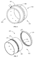
FIG. 6 is a perspective view of a gas turbine combustor fuel manifold, according to an embodiment of the present disclosure. -
FIG. 7 is an exploded view of the gas turbine combustor fuel manifold ofFIG. 1 separating the first component section and the second component section, according to an embodiment of the present disclosure. - Wherever possible, the same reference numbers will be used throughout the drawings to represent the same parts.
- Provided are exemplary components, turbine components and methods of forming components and turbine components. Embodiments of the present disclosure, in comparison to methods and products not utilizing one or more features disclosed herein, provide a more efficient and cost effective method of cladding the interior surface of a plenum with a corrosion-resistant material, reduce corrosion of the interior surface of a plenum such as a gas turbine manifold, lengthen the service life manifolds contacting corrosive fluids, and reduce repair costs associated with corrosion of manifolds.
- Referring to
FIG. 1 , acomponent 100 includes afirst component section 102 and asecond component section 104 joined to form ahollow structure 106. Thehollow structure 106 defines a plenum 108 including aninterior surface 110. The plenum 108 includes awidth 112 and alength 114, thelength 114 being greater than thewidth 112. Thefirst component section 102 includes afirst substrate material 116 and thesecond component section 104 includes asecond substrate material 118. In one embodiment, thelength 114 extends along a circumferential path of the hollow structure 106 (see, e.g.FIG, 6 ). - The
first substrate material 116 and thesecond substrate material 118 each, independently, is selected from any suitable material, including, but not limited to, steel, carbon steel, low-alloy steel, Cr-Mo steel, and combinations thereof. Thefirst substrate material 116 and thesecond substrate material 118 may be the same material or may be different materials. - Referring to
FIGS. 2 and 3 , thefirst component section 102 includes afirst mating ridge 120 and asecond mating ridge 122, and thesecond component section 104 includes athird mating ridge 124 and afourth mating ridge 126. - Referring again to
FIG. 1 , thefirst mating ridge 120 is joined to thethird mating ridge 124 along thelength 114 of the plenum 108 and thesecond mating ridge 122 is joined to thefourth mating ridge 126 along thelength 114 of the plenum 108. A corrosion-resistant cladding layer 128 including a corrosion-resistant material 130 overlays theinterior surface 110 of the plenum 108. - The corrosion-
resistant material 130 may be any suitable material, including, but not limited to, a nickel-based alloy, a stainless steel, or combinations thereof. In one embodiment, the corrosion-resistant material has a composition, by weight, of about 5% iron, between about 20% and about 23% chromium, up to about 0.5% silicon, between about 8% and about 10% molybdenum, up to about 0.5% manganese, up to about 0.1% carbon, and a balance nickel (available commercially as INCONEL 625 - "INCONEL" is a federally registered trademark of alloys produced by Huntington Alloys Corporation, Huntington, West Virginia). - The
thickness 132 of the corrosion-resistant cladding layer 128 may be anysuitable thickness 132, including, but not limited to athickness 132 of between about 0.005 inches to about 0.05 inches, alternatively about 0.005 inches to about 0.025 inches, alternatively about 0.025 inches to about 0.05 inches, alternatively about 0.005 inches to about 0.02 inches, alternatively about 0.015 inches to about 0.03 inches, alternatively about 0.025 inches to about 0.04 inches, alternatively about 0.035 inches to about 0.05 inches. - Referring to
FIGS. 1, 2 and 3 , the corrosion-resistant cladding layer 126 further includes a first corrosion-resistant segment 134 and a second corrosionresistant segment 136, wherein the first corrosion-resistant segment 134 is disposed on afirst surface 200 of thefirst component section 102, and the second corrosion-resistant segment 136 is disposed on asecond surface 300 of thesecond component section 104. - Referring to
FIG. 4 , in one embodiment, at least one of the first corrosion-resistant segment 134 (not shown) and the second corrosion resistant segment 136 (shown) includes a plurality ofsub-segments 400, wherein of the plurality ofsub-segments 400 are joined together atseams 402. - A method of forming the
component 100 includes providing thefirst component section 102 and thesecond component section 104. The first corrosion-resistant segment 134 is applied to thefirst surface 200 and the second corrosion-resistant segment 136 is applied to thesecond surface 300. In one embodiment, applying the first corrosion-resistant segment 134 and the second corrosion-resistant segment 136 includes affixing the first corrosion-resistant segment 134 to thefirst surface 200 and affixing the second corrosion-resistant segment 136 to thesecond surface 300. In a further embodiment, at least one of the first corrosion-resistant segment 134 and the second corrosionresistant segment 136 includes a plurality ofsub-segments 400, wherein each of the plurality ofsub-segments 400 is separately affixed to one of thefirst surface 200 and thesecond surface 300. The plurality ofsub-segments 400 may be affixed one at a time or affixed in groups of two ormore sub-segments 400. - Affixing may include any suitable technique, including, but not limited to welding, brazing, or a combination thereof. Welding may include any suitable welding technique, including, but not limited to, shielded metal arc welding, gas tungsten arc welding, gas metal arc welding, flux-cored arc welding, submerged arc welding, electroslag arc welding, resistance welding, spot welding, seam welding, butt welding, flash welding, projection, welding, upset welding, laser beam welding, electron beam welding, laser-hybrid welding, laser cladding, x-ray welding, ultrasonic welding, explosion welding, friction welding, friction stir welding, magnetic pulse welding, co-extrusion welding, cold welding, diffusion welding, exothermic welding, high frequency welding, hot pressure welding, induction welding, roll welding, and combinations there. Brazing may including any suitable brazing technique, including, but not limited to, torch brazing, furnace brazing, silver brazing, braze welding, vacuum brazing, dip brazing and combinations thereof.
- Following affixing the first corrosion-
resistant segment 134 to thefirst surface 200 and affixing the second corrosion-resistant segment 136 to thesecond surface 300, thefirst component section 102 is joined to thesecond component section 104. Joining thefirst component section 102 to thesecond component section 104 includes fusing the first corrosion-resistant segment 134 to the second corrosion-resistant segment 136 to form the corrosion-resistant cladding layer 128 which overlays theinterior surface 110 of the plenum 108, and joining thefirst mating ridge 120 to thethird mating ridge 124 and thesecond mating ridge 122 to thefourth mating ridge 126, along the length of the plenum 108. - In one embodiment, fusing the first corrosion-
resistant segment 134 to the second corrosion-resistant segment 136 and joining thefirst mating ridge 120 to thethird mating ridge 124 along thelength 114 of the plenum 108, and joining thefirst mating ridge 120 to thethird mating ridge 124 and thesecond mating ridge 122 to thefourth mating ridge 126, along the length of the plenum 108, is accomplished with a single, contemporaneous, joining process. In an alternate embodiment, the first corrosion-resistant segment 134 is fused to the second corrosion-resistant segment 136 with a first joining process, and then thefirst mating ridge 120 is joined to thethird mating ridge 124 and thesecond mating ridge 122 is joined to thefourth mating ridge 126 with a second joining process, wherein the first joining process and the second joining process may be the same joining process or a different joining process. - A joining process, whether the single, contemporaneous, joining process, the first joining process, the second joining process or an additional joining process, may be any suitable joining process, including, but not limited to a welding process, a brazing process, or a combination thereof. A welding process may include any suitable welding technique, including, but not limited to, shielded metal arc welding, gas tungsten arc welding, gas metal arc welding, flux-cored arc welding, submerged arc welding, electroslag arc welding, resistance welding, spot welding, seam welding, butt welding, flash welding, projection, welding, upset welding, laser beam welding, electron beam welding, laser-hybrid welding, laser cladding, x-ray welding, ultrasonic welding, explosion welding, friction welding, friction stir welding, magnetic pulse welding, co-extrusion welding, cold welding, diffusion welding, exothermic welding, high frequency welding, hot pressure welding, induction welding, roll welding, and combinations there. A brazing process may including any suitable brazing technique, including, but not limited to, torch brazing, furnace brazing, silver brazing, braze welding, vacuum brazing, dip brazing and combinations thereof.
- In one embodiment, the first joining process includes an additive root pass to join the first corrosion-
resistant segment 134 and the second corrosion-resistant segment 136. As used herein, "additive root pass" indicates a joining technique which deposits a corrosion-resistant material to initiate the joining of the corrosion-resistant material 130 of the first corrosion-resistant segment 134 and the corrosion-resistant material 130 of the second corrosion-resistant segment 136. The corrosion-resistant material deposited by the root pass may be the corrosion-resistant material 130 of the first corrosion-resistant segment 134 and the second corrosion-resistant segment 136 or a different corrosion-resistant material. The additive root pass fuses the first corrosion-resistant segment 134 and the second corrosion-resistant segment 136, forming the corrosionresistant cladding layer 128 and the plenum 108. Following the additive root pass, thefirst mating ridge 120 is joined to thethird mating ridge 124 and thesecond mating ridge 122 is joined to thefourth mating ridge 126 with a second joining process, forming thecomponent 100. The second joining process and the first joining process may be the same joining process or a different joining process, wherein the second joining process is any suitable joining process for joining thefirst substrate material 116 and thesecond substrate material 118. - Referring to
FIG. 5 , in one embodiment, thefirst component section 102, thesecond component section 104, the first corrosion-resistant segment 134 and the second corrosion-resistant segment 136 are configured for an additive root pass. The first corrosion-resistant segment 134 and the second corrosion-resistant segment 136 extend beyond thefirst component section 102 and thesecond component section 104, such that when thefirst component section 102 and thesecond component section 104 are arranged adjacent to one another for joining, the first corrosion-resistant segment 134 and the second corrosion-resistant segment 136 define a first exposedpotion 500 and a second exposedportion 502, and thefirst component section 102 and thesecond component section 104 define afirst trench 504 and asecond trench 506. The additive root pass deposits a corrosion-resistant material on the first exposedpotion 500 and the second exposedportion 502. - In a further embodiment, the
first mating ridge 120, thesecond mating ridge 122, thethird mating ridge 124 and thefourth mating ridge 126 include any suitable conformations to define thefirst trench 504 and thesecond trench 506, including, but not limited to right angles, bevels, chamfers, and combinations thereof. Suitable bevels, chamfers, and combinations thereof include, but are not limited to, straight edges, curved edges, tapered edges, simple edges, complex edges, and combinations thereof. At least one of thefirst mating ridge 120 and thethird mating ridge 124 includes a bevel, chamfer, or a combination thereof, and at least one of thesecond mating ridge 122 and thefourth mating ridge 126, includes a bevel, chamfer, or a combination thereof. - Including an additive root pass to fuse the first corrosion-
resistant segment 134 and the second corrosion-resistant segment 136 prior to joining thefirst mating ridge 120 to thethird mating ridge 124 and thesecond mating ridge 122 to thefourth mating ridge 126 may increase the corrosion-resisting properties of the corrosion-resistant cladding layer 128 relative a corrosion-resistant cladding layer 126 formed without an additive root pass. Without being bound by theory, it is believed that the additive root pass may reduce or eliminate the potential for a material other than the corrosion-resistant material 130 from intermingling with the corrosion-resistant material 130 in the corrosion-resistant cladding layer 126 and contacting a corrosive fluid in the plenum 108. - Referring to
FIGS. 6 and 7 , thehollow structure 106 of thecomponent 100 may be a manifold 600. In one embodiment, thecomponent 100 is agas turbine manifold 602. In a further embodiment, thegas turbine manifold 602 is a combustor fuel manifold 604 (also known as a quat manifold, a combustor quat manifold or a quat fuel manifold). In another embodiment, thegas turbine manifold 600 is a combustor gas manifold (not shown). - While the invention has been described with reference to a preferred embodiment, it will be understood by those skilled in the art that various changes may be made and equivalents may be substituted for elements thereof without departing from the scope of the invention. In addition, many modifications may be made to adapt a particular situation or material to the teachings of the invention without departing from the essential scope thereof. Therefore, it is intended that the invention not be limited to the particular embodiment disclosed but that the invention will include all embodiments falling within the scope of the appended claims.
- Various aspects and embodiments of the present invention are defined by the following numbered clauses:
- 1. A component, comprising:
- a first component section and a second component section joined to form a hollow structure, wherein:
- the hollow structure defines a plenum including an interior surface, a width and a length, the length being greater than the width;
- the first component section includes a first substrate material and the second component section includes a second substrate material;
- the first component section includes a first mating ridge and a second mating ridge;
- the second component section includes a third mating ridge and a fourth mating ridge;
- the first mating ridge is joined to the third mating ridge along the length of the plenum; and
- the second mating ridge is joined to the fourth mating ridge along the length of the plenum; and
- a corrosion-resistant cladding layer including a corrosion-resistant material,
- wherein the corrosion-resistant cladding layer overlays the interior surface of the plenum.
- a first component section and a second component section joined to form a hollow structure, wherein:
- 2. The component of clause 1, wherein the component is a gas turbine manifold.
- 3. The component of any preceding clause, wherein the component is a combustor fuel manifold or a combustor gas manifold.
- 4. The component of any preceding clause, wherein the first substrate material and the second substrate material each, independently, is selected from the group consisting of steel, carbon steel, low-alloy steel, Cr-Mo steel, and combinations thereof.
- 5. The component of any preceding clause, wherein the first substrate material and the second substrate material are each independently a carbon steel or a Cr-Mo steel.
- 6. The component of any preceding clause, wherein the corrosion-resistant material is selected from the group consisting of a nickel-based alloy, a stainless steel, or combinations thereof.
- 7. The component of any preceding clause, wherein the corrosion-resistant cladding layer includes a thickness of between about 0.005 inches to about 0.05 inches.
- 8. A gas turbine component, comprising:
- a first component section and a second component section joined to form a combustor fuel manifold, wherein:
- the combustor manifold defines a plenum including an interior surface, a width and a length, the length being greater than the width;
- the first component section includes a first substrate material and the second component section includes a second substrate material;
- the first component section includes a first mating ridge and a second mating ridge;
- the second component section includes a third mating ridge and a fourth mating ridge;
- the first mating ridge is joined to the third mating ridge along the length of the plenum; and
- the second mating ridge is joined to the fourth mating ridge along the length of the plenum; and
- a corrosion-resistant cladding layer including a corrosion-resistant material,
- wherein the corrosion-resistant cladding layer overlays the interior surface of the plenum.
- a first component section and a second component section joined to form a combustor fuel manifold, wherein:
- 9. The component of any preceding clause, wherein the first substrate material and the second substrate material each, independently, is selected from the group consisting of steel, carbon steel, low-alloy steel, Cr-Mo steel, and combinations thereof.
- 10. The component of any preceding clause, wherein the corrosion-resistant material is selected from the group consisting of a nickel-based alloy, a stainless steel, or combinations thereof.
- 11. The component of any preceding clause, wherein the corrosion-resistant cladding layer includes a thickness of between about 0.005 inches to about 0.05 inches.
- 12. A method of forming a component, comprising:
- providing a first component section and a second component section, wherein:
- the first component section includes a first substrate material and the second component section includes a second substrate material;
- the first component section includes a first mating ridge, a second mating ridge and a first surface between the first mating ridge and the second mating ridge; and
- the second component section includes a third mating ridge, a fourth mating ridge, and a second surface between the first mating ridge and the second mating ridge;
- applying a first corrosion-resistant segment including a corrosion-resistant material to the first surface and a second corrosion-resistant segment including the corrosion-resistant material to the second surface; and
- joining the first component section and the second component section to form the component defining a plenum including an interior surface, a width and a length, the length being greater than the width, wherein joining the first component section and the second component section includes:
- fusing the first corrosion-resistant segment and the second corrosion-resistant segment into a corrosion-resistant cladding layer, wherein the corrosion-resistant cladding layer overlays the interior surface of the plenum;
- joining the first mating ridge to the third mating ridge along the length of the plenum; and
- joining the second mating ridge to the fourth mating ridge along the length of the plenum.
- providing a first component section and a second component section, wherein:
- 13. The method of any preceding clause, wherein the gas turbine component is a gas turbine manifold.
- 14. The method of any preceding clause, wherein the gas turbine component is a combustor fuel manifold or a combustor gas manifold.
- 15. The method of any preceding clause, wherein the applying the first corrosion-resistant segment and the second corrosion-resistant segment includes affixing the first corrosion-resistant segment to the first surface and affixing the second corrosion-resistant segment to the second surface, wherein affixing includes a technique selected from the group consisting of welding, brazing, or a combination thereof.
- 16. The method of any preceding clause, wherein at least one of the first corrosion-resistant segment and the second corrosion resistant segment includes a plurality of sub-segments, each of which plurality of sub-segments is separately affixed to one of the first surface and the second surface.
- 17. The method of any preceding clause, wherein joining the first component section and the second component section includes an additive root pass depositing corrosion-resistant material between the first corrosion-resistant segment and the second corrosion-resistant segment.
- 18. The method of any preceding clause, wherein joining the first component section and the second component section includes a technique selected from the group consisting of welding, brazing, or a combination thereof.
- 19. The method of any preceding clause, wherein the corrosion-resistant metal is selected from the group consisting of a nickel-based alloy, a stainless steel, or combinations thereof.
- 20. The method of any preceding clause, wherein the first substrate material and the second substrate material each, independently, is selected from the group consisting of steel, carbon steel, low-alloy steel, Cr-Mo steel, and combinations thereof.
Claims (15)
- A component (100), comprising:a first component section (102) and a second component section (104) joined to form a hollow structure (106), wherein:the hollow structure (106) defines a plenum (108) including an interior surface (110), a width (112) and a length (114), the length (114) being greater than the width (112);the first component section (102) includes a first substrate material (116) and the second component section (104) includes a second substrate material (118);the first component section (102) includes a first mating ridge (120) and a second mating ridge (122);the second component section (104) includes a third mating ridge (124) and a fourth mating ridge (126);the first mating ridge (120) is joined to the third mating ridge (124) along the length (114) of the plenum (108); andthe second mating ridge (122) is joined to the fourth mating ridge (126) along the length (114) of the plenum (108); anda corrosion-resistant cladding layer (128) including a corrosion-resistant material (130),wherein the corrosion-resistant cladding layer (128) overlays the interior surface (110) of the plenum (108).
- The component (100) of claim 1, wherein the component (100) is a gas turbine manifold (602).
- The component (100) of claim 2, wherein the component (100) is a combustor fuel manifold (604) or a combustor gas manifold.
- The component (100) of claim 1, 2 or 3, wherein the first substrate material (116) and the second substrate material (118) each, independently, is selected from the group consisting of steel, carbon steel, low-alloy steel, Cr-Mo steel, and combinations thereof.
- The component (100) of claim 4, wherein the first substrate material (116) and the second substrate material (118) are each independently a carbon steel or a Cr-Mo steel.
- The component (100) of any preceding claim, wherein the corrosion-resistant material (130) is selected from the group consisting of a nickel-based alloy, a stainless steel, or combinations thereof.
- The component (100) of any preceding claim, wherein the corrosion-resistant cladding layer (128) includes a thickness (132) of between about 0.005 inches to about 0.05 inches.
- A gas turbine component (100), comprising:a first component section (102) and a second component section (104) joined to form a combustor fuel manifold (604), wherein:the combustor manifold (604) defines a plenum (108) including an interior surface (110), a width (112) and a length (114), the length (114) being greater than the width (112);the first component section (102) includes a first substrate material (116) and the second component section (104) includes a second substrate material (118);the first component section (102) includes a first mating ridge (120) and a second mating ridge (122);the second component section (104) includes a third mating ridge (124) and a fourth mating ridge (126);the first mating ridge (120) is joined to the third mating ridge (124) along the length (114) of the plenum (108); andthe second mating ridge (122) is joined to the fourth mating ridge (126) along the length (114) of the plenum (108); anda corrosion-resistant cladding layer (128) including a corrosion-resistant material (130),wherein the corrosion-resistant cladding layer (128) overlays the interior surface (110) of the plenum (108).
- A method of forming a component (100), comprising:providing a first component section (102) and a second component section (104), wherein:the first component section (102) includes a first substrate material (116) and the second component section (104) includes a second substrate material (118);the first component section (102) includes a first mating ridge (120), a second mating ridge (122) and a first surface (200) between the first mating ridge (120) and the second mating ridge (122); andthe second component section (104) includes a third mating ridge (124), a fourth mating ridge (126), and a second surface (300) between the first mating ridge (124) and the second mating ridge (126);applying a first corrosion-resistant segment (134) including a corrosion-resistant material (130) to the first surface (200) and a second corrosion-resistant segment (136) including the corrosion-resistant material (134) to the second surface (300); andjoining the first component section (102) and the second component section (104) to form the component (100) defining a plenum (108) including an interior surface (110), a width (112) and a length (114), the length (114) being greater than the width (112), wherein joining the first component section (102) and the second component section (104) includes:fusing the first corrosion-resistant segment (134) and the second corrosion-resistant segment (136) into a corrosion-resistant cladding layer (128), wherein the corrosion-resistant cladding layer (128) overlays the interior surface (110) of the plenum (108);joining the first mating ridge (120) to the third mating ridge (124) along the length (114) of the plenum (108); andjoining the second mating ridge (122) to the fourth mating ridge (126) along the length (114) of the plenum (108).
- The method of claim 9, wherein the gas turbine component (100) is a gas turbine manifold (602).
- The method of claim 10, wherein the gas turbine component (100) is a combustor fuel manifold (604) or a combustor gas manifold.
- The method of claim 9, 10 or 11, wherein the applying the first corrosion-resistant segment (134) and the second corrosion-resistant segment (136) includes affixing the first corrosion-resistant segment (134) to the first surface (200) and affixing the second corrosion-resistant segment (136) to the second surface (300), wherein affixing includes a technique selected from the group consisting of welding, brazing, or a combination thereof.
- The method of claim 12, wherein at least one of the first corrosion-resistant segment (134) and the second corrosion resistant segment (136) includes a plurality of sub-segments (400), each of which plurality of sub-segments (400) is separately affixed to one of the first surface (200) and the second surface (300).
- The method of any of claim 9 to 13, wherein joining the first component section (102) and the second component section (104) includes an additive root pass depositing corrosion-resistant material (130) between the first corrosion-resistant segment (102) and the second corrosion-resistant segment (104).
- The method of claim 14, wherein joining the first component section (102) and the second component section (104) includes a technique selected from the group consisting of welding, brazing, or a combination thereof.
Applications Claiming Priority (1)
| Application Number | Priority Date | Filing Date | Title |
|---|---|---|---|
| US14/717,074 US10119473B2 (en) | 2015-05-20 | 2015-05-20 | Component, gas turbine component and method of forming |
Publications (2)
| Publication Number | Publication Date |
|---|---|
| EP3144505A1 true EP3144505A1 (en) | 2017-03-22 |
| EP3144505B1 EP3144505B1 (en) | 2020-11-25 |
Family
ID=56194218
Family Applications (1)
| Application Number | Title | Priority Date | Filing Date |
|---|---|---|---|
| EP16169761.0A Active EP3144505B1 (en) | 2015-05-20 | 2016-05-16 | Gas turbine component and method of forming |
Country Status (4)
| Country | Link |
|---|---|
| US (1) | US10119473B2 (en) |
| EP (1) | EP3144505B1 (en) |
| JP (1) | JP6786259B2 (en) |
| CN (1) | CN106168167A (en) |
Families Citing this family (1)
| Publication number | Priority date | Publication date | Assignee | Title |
|---|---|---|---|---|
| US9765727B2 (en) * | 2014-03-03 | 2017-09-19 | Federal-Mogul Llc | One-piece piston featuring additive machining produced combustion bowl rim and cooling gallery |
Citations (4)
| Publication number | Priority date | Publication date | Assignee | Title |
|---|---|---|---|---|
| US20020148427A1 (en) * | 2001-04-04 | 2002-10-17 | Jones Bart R. | Adhesively bonded engine intake manifold assembly |
| WO2004033116A1 (en) * | 2002-10-07 | 2004-04-22 | Coatings For Industry, Inc. | Formation of corrosion-resistant coating |
| US20050188699A1 (en) * | 2004-02-27 | 2005-09-01 | Pratt & Whitney Canada Corp. | Apparatus for fuel transport and the like |
| EP2236793A1 (en) * | 2009-03-17 | 2010-10-06 | Siemens Aktiengesellschaft | Burner assembly |
Family Cites Families (15)
| Publication number | Priority date | Publication date | Assignee | Title |
|---|---|---|---|---|
| US4413477A (en) | 1980-12-29 | 1983-11-08 | General Electric Company | Liner assembly for gas turbine combustor |
| FR2579738B1 (en) | 1985-03-29 | 1987-06-26 | Framatome Sa | METHOD FOR REPAIRING A STEAM GENERATOR TUBE BY LINING |
| JP2904701B2 (en) | 1993-12-15 | 1999-06-14 | 株式会社日立製作所 | Gas turbine and gas turbine combustion device |
| US6401320B1 (en) * | 2000-01-14 | 2002-06-11 | Manfred A. A. Lupke | Method of simultaneously making a plurality of metallic pipes |
| US6715293B2 (en) | 2002-03-28 | 2004-04-06 | United Technologies Corporation | Scram jet engine design |
| US7191750B2 (en) | 2004-04-06 | 2007-03-20 | Siemens Canada Limited | Laser welded manifold |
| US8096130B2 (en) * | 2006-07-20 | 2012-01-17 | Pratt & Whitney Canada Corp. | Fuel conveying member for a gas turbine engine |
| US8234873B2 (en) * | 2008-08-28 | 2012-08-07 | Woodward, Inc. | Multi passage fuel manifold and methods of construction |
| US8375726B2 (en) | 2008-09-24 | 2013-02-19 | Siemens Energy, Inc. | Combustor assembly in a gas turbine engine |
| US8590315B2 (en) * | 2010-06-01 | 2013-11-26 | General Electric Company | Extruded fluid manifold for gas turbomachine combustor casing |
| US8713944B2 (en) | 2010-09-23 | 2014-05-06 | Delavan Inc. | High temperature manifolds for gas turbine engines |
| US10240533B2 (en) | 2011-11-22 | 2019-03-26 | United Technologies Corporation | Fuel distribution within a gas turbine engine combustor |
| US20130232986A1 (en) * | 2012-03-12 | 2013-09-12 | General Electric Company | Combustor and method for reducing thermal stresses in a combustor |
| US20150083692A1 (en) * | 2012-09-12 | 2015-03-26 | Gerald J. Bruck | Laser cladding system filler material distribution apparatus |
| GB201216703D0 (en) * | 2012-09-19 | 2012-10-31 | Rolls Royce Plc | A boroscope and a method of laser processing a component within an assembled apparatus using a boroscope |
-
2015
- 2015-05-20 US US14/717,074 patent/US10119473B2/en active Active
-
2016
- 2016-05-11 JP JP2016094980A patent/JP6786259B2/en not_active Expired - Fee Related
- 2016-05-16 EP EP16169761.0A patent/EP3144505B1/en active Active
- 2016-05-20 CN CN201610336572.6A patent/CN106168167A/en active Pending
Patent Citations (4)
| Publication number | Priority date | Publication date | Assignee | Title |
|---|---|---|---|---|
| US20020148427A1 (en) * | 2001-04-04 | 2002-10-17 | Jones Bart R. | Adhesively bonded engine intake manifold assembly |
| WO2004033116A1 (en) * | 2002-10-07 | 2004-04-22 | Coatings For Industry, Inc. | Formation of corrosion-resistant coating |
| US20050188699A1 (en) * | 2004-02-27 | 2005-09-01 | Pratt & Whitney Canada Corp. | Apparatus for fuel transport and the like |
| EP2236793A1 (en) * | 2009-03-17 | 2010-10-06 | Siemens Aktiengesellschaft | Burner assembly |
Also Published As
| Publication number | Publication date |
|---|---|
| EP3144505B1 (en) | 2020-11-25 |
| JP6786259B2 (en) | 2020-11-18 |
| US20160341127A1 (en) | 2016-11-24 |
| JP2016217695A (en) | 2016-12-22 |
| CN106168167A (en) | 2016-11-30 |
| US10119473B2 (en) | 2018-11-06 |
Similar Documents
| Publication | Publication Date | Title |
|---|---|---|
| CN103459076B (en) | Overlaying structure and the method that overlaying structure is provided | |
| JP6108049B2 (en) | Spot welding method for plated steel sheet | |
| US2963129A (en) | Dissimilar metal welded joint with protective overlay | |
| US9316341B2 (en) | Coating compositions, applications thereof, and methods of forming | |
| US6489583B1 (en) | Shimmed electron beam welding process | |
| JP6025620B2 (en) | Submerged arc welding method, method of manufacturing steel pipe using the submerged arc welding method, welded joint, and steel pipe having the welded joint | |
| JP5978633B2 (en) | Manufacturing method of water-cooled wall panel | |
| TW200821503A (en) | Boiler water wall panel | |
| CN108637518A (en) | Welding groove and welding method of oil and gas composite transportation pipeline | |
| JP6619232B2 (en) | Welding method | |
| EP3317571B1 (en) | A method of producing a tube arrangement, a tube arrangement and a furnace provided with such a tube arrangement | |
| CN1950173B (en) | Welding filler for welding dissimilar alloy steels and method of use thereof | |
| JP3170720B2 (en) | Dissimilar material welding method | |
| US20150266136A1 (en) | Welding electrode | |
| EP3144505B1 (en) | Gas turbine component and method of forming | |
| JPWO2014024365A1 (en) | Submerged arc welding method, welded joint and steel pipe manufacturing method | |
| CN108798805A (en) | Handle the method for turbine baffle and processed turbine baffle | |
| CN103206723B (en) | Fuel nozzle and the technique manufacturing fuel nozzle | |
| JP5538079B2 (en) | Clad steel material joining method and structure | |
| EP2631322A1 (en) | Alloy-coated boiler component | |
| JP3597375B2 (en) | Joint and joint method of titanium or titanium alloy and iron-based material | |
| Patrick et al. | Challenges Welding Duplex and Super Duplex Stainless Steel | |
| JPH08152290A (en) | Method for welding different metals and welded structure thereof | |
| JPH03207575A (en) | Circumferential welding method for double pipes | |
| EP2564978B1 (en) | Filler metal chemistry for improved weldability of super alloys |
Legal Events
| Date | Code | Title | Description |
|---|---|---|---|
| PUAI | Public reference made under article 153(3) epc to a published international application that has entered the european phase |
Free format text: ORIGINAL CODE: 0009012 |
|
| STAA | Information on the status of an ep patent application or granted ep patent |
Free format text: STATUS: THE APPLICATION HAS BEEN PUBLISHED |
|
| AK | Designated contracting states |
Kind code of ref document: A1 Designated state(s): AL AT BE BG CH CY CZ DE DK EE ES FI FR GB GR HR HU IE IS IT LI LT LU LV MC MK MT NL NO PL PT RO RS SE SI SK SM TR |
|
| AX | Request for extension of the european patent |
Extension state: BA ME |
|
| STAA | Information on the status of an ep patent application or granted ep patent |
Free format text: STATUS: REQUEST FOR EXAMINATION WAS MADE |
|
| 17P | Request for examination filed |
Effective date: 20170922 |
|
| RBV | Designated contracting states (corrected) |
Designated state(s): AL AT BE BG CH CY CZ DE DK EE ES FI FR GB GR HR HU IE IS IT LI LT LU LV MC MK MT NL NO PL PT RO RS SE SI SK SM TR |
|
| GRAP | Despatch of communication of intention to grant a patent |
Free format text: ORIGINAL CODE: EPIDOSNIGR1 |
|
| STAA | Information on the status of an ep patent application or granted ep patent |
Free format text: STATUS: GRANT OF PATENT IS INTENDED |
|
| INTG | Intention to grant announced |
Effective date: 20200615 |
|
| GRAS | Grant fee paid |
Free format text: ORIGINAL CODE: EPIDOSNIGR3 |
|
| GRAA | (expected) grant |
Free format text: ORIGINAL CODE: 0009210 |
|
| STAA | Information on the status of an ep patent application or granted ep patent |
Free format text: STATUS: THE PATENT HAS BEEN GRANTED |
|
| AK | Designated contracting states |
Kind code of ref document: B1 Designated state(s): AL AT BE BG CH CY CZ DE DK EE ES FI FR GB GR HR HU IE IS IT LI LT LU LV MC MK MT NL NO PL PT RO RS SE SI SK SM TR |
|
| REG | Reference to a national code |
Ref country code: GB Ref legal event code: FG4D |
|
| REG | Reference to a national code |
Ref country code: CH Ref legal event code: EP |
|
| REG | Reference to a national code |
Ref country code: AT Ref legal event code: REF Ref document number: 1338573 Country of ref document: AT Kind code of ref document: T Effective date: 20201215 |
|
| REG | Reference to a national code |
Ref country code: DE Ref legal event code: R096 Ref document number: 602016048424 Country of ref document: DE |
|
| REG | Reference to a national code |
Ref country code: IE Ref legal event code: FG4D |
|
| REG | Reference to a national code |
Ref country code: AT Ref legal event code: MK05 Ref document number: 1338573 Country of ref document: AT Kind code of ref document: T Effective date: 20201125 |
|
| REG | Reference to a national code |
Ref country code: NL Ref legal event code: MP Effective date: 20201125 |
|
| PG25 | Lapsed in a contracting state [announced via postgrant information from national office to epo] |
Ref country code: GR Free format text: LAPSE BECAUSE OF FAILURE TO SUBMIT A TRANSLATION OF THE DESCRIPTION OR TO PAY THE FEE WITHIN THE PRESCRIBED TIME-LIMIT Effective date: 20210226 Ref country code: FI Free format text: LAPSE BECAUSE OF FAILURE TO SUBMIT A TRANSLATION OF THE DESCRIPTION OR TO PAY THE FEE WITHIN THE PRESCRIBED TIME-LIMIT Effective date: 20201125 Ref country code: PT Free format text: LAPSE BECAUSE OF FAILURE TO SUBMIT A TRANSLATION OF THE DESCRIPTION OR TO PAY THE FEE WITHIN THE PRESCRIBED TIME-LIMIT Effective date: 20210325 Ref country code: RS Free format text: LAPSE BECAUSE OF FAILURE TO SUBMIT A TRANSLATION OF THE DESCRIPTION OR TO PAY THE FEE WITHIN THE PRESCRIBED TIME-LIMIT Effective date: 20201125 Ref country code: NO Free format text: LAPSE BECAUSE OF FAILURE TO SUBMIT A TRANSLATION OF THE DESCRIPTION OR TO PAY THE FEE WITHIN THE PRESCRIBED TIME-LIMIT Effective date: 20210225 |
|
| PG25 | Lapsed in a contracting state [announced via postgrant information from national office to epo] |
Ref country code: AT Free format text: LAPSE BECAUSE OF FAILURE TO SUBMIT A TRANSLATION OF THE DESCRIPTION OR TO PAY THE FEE WITHIN THE PRESCRIBED TIME-LIMIT Effective date: 20201125 Ref country code: IS Free format text: LAPSE BECAUSE OF FAILURE TO SUBMIT A TRANSLATION OF THE DESCRIPTION OR TO PAY THE FEE WITHIN THE PRESCRIBED TIME-LIMIT Effective date: 20210325 Ref country code: SE Free format text: LAPSE BECAUSE OF FAILURE TO SUBMIT A TRANSLATION OF THE DESCRIPTION OR TO PAY THE FEE WITHIN THE PRESCRIBED TIME-LIMIT Effective date: 20201125 Ref country code: LV Free format text: LAPSE BECAUSE OF FAILURE TO SUBMIT A TRANSLATION OF THE DESCRIPTION OR TO PAY THE FEE WITHIN THE PRESCRIBED TIME-LIMIT Effective date: 20201125 Ref country code: PL Free format text: LAPSE BECAUSE OF FAILURE TO SUBMIT A TRANSLATION OF THE DESCRIPTION OR TO PAY THE FEE WITHIN THE PRESCRIBED TIME-LIMIT Effective date: 20201125 Ref country code: BG Free format text: LAPSE BECAUSE OF FAILURE TO SUBMIT A TRANSLATION OF THE DESCRIPTION OR TO PAY THE FEE WITHIN THE PRESCRIBED TIME-LIMIT Effective date: 20210225 |
|
| REG | Reference to a national code |
Ref country code: LT Ref legal event code: MG9D |
|
| PG25 | Lapsed in a contracting state [announced via postgrant information from national office to epo] |
Ref country code: HR Free format text: LAPSE BECAUSE OF FAILURE TO SUBMIT A TRANSLATION OF THE DESCRIPTION OR TO PAY THE FEE WITHIN THE PRESCRIBED TIME-LIMIT Effective date: 20201125 |
|
| PG25 | Lapsed in a contracting state [announced via postgrant information from national office to epo] |
Ref country code: SK Free format text: LAPSE BECAUSE OF FAILURE TO SUBMIT A TRANSLATION OF THE DESCRIPTION OR TO PAY THE FEE WITHIN THE PRESCRIBED TIME-LIMIT Effective date: 20201125 Ref country code: RO Free format text: LAPSE BECAUSE OF FAILURE TO SUBMIT A TRANSLATION OF THE DESCRIPTION OR TO PAY THE FEE WITHIN THE PRESCRIBED TIME-LIMIT Effective date: 20201125 Ref country code: SM Free format text: LAPSE BECAUSE OF FAILURE TO SUBMIT A TRANSLATION OF THE DESCRIPTION OR TO PAY THE FEE WITHIN THE PRESCRIBED TIME-LIMIT Effective date: 20201125 Ref country code: LT Free format text: LAPSE BECAUSE OF FAILURE TO SUBMIT A TRANSLATION OF THE DESCRIPTION OR TO PAY THE FEE WITHIN THE PRESCRIBED TIME-LIMIT Effective date: 20201125 Ref country code: EE Free format text: LAPSE BECAUSE OF FAILURE TO SUBMIT A TRANSLATION OF THE DESCRIPTION OR TO PAY THE FEE WITHIN THE PRESCRIBED TIME-LIMIT Effective date: 20201125 Ref country code: CZ Free format text: LAPSE BECAUSE OF FAILURE TO SUBMIT A TRANSLATION OF THE DESCRIPTION OR TO PAY THE FEE WITHIN THE PRESCRIBED TIME-LIMIT Effective date: 20201125 |
|
| REG | Reference to a national code |
Ref country code: DE Ref legal event code: R097 Ref document number: 602016048424 Country of ref document: DE |
|
| PG25 | Lapsed in a contracting state [announced via postgrant information from national office to epo] |
Ref country code: DK Free format text: LAPSE BECAUSE OF FAILURE TO SUBMIT A TRANSLATION OF THE DESCRIPTION OR TO PAY THE FEE WITHIN THE PRESCRIBED TIME-LIMIT Effective date: 20201125 |
|
| PLBE | No opposition filed within time limit |
Free format text: ORIGINAL CODE: 0009261 |
|
| STAA | Information on the status of an ep patent application or granted ep patent |
Free format text: STATUS: NO OPPOSITION FILED WITHIN TIME LIMIT |
|
| PG25 | Lapsed in a contracting state [announced via postgrant information from national office to epo] |
Ref country code: NL Free format text: LAPSE BECAUSE OF FAILURE TO SUBMIT A TRANSLATION OF THE DESCRIPTION OR TO PAY THE FEE WITHIN THE PRESCRIBED TIME-LIMIT Effective date: 20201125 Ref country code: IT Free format text: LAPSE BECAUSE OF FAILURE TO SUBMIT A TRANSLATION OF THE DESCRIPTION OR TO PAY THE FEE WITHIN THE PRESCRIBED TIME-LIMIT Effective date: 20201125 Ref country code: AL Free format text: LAPSE BECAUSE OF FAILURE TO SUBMIT A TRANSLATION OF THE DESCRIPTION OR TO PAY THE FEE WITHIN THE PRESCRIBED TIME-LIMIT Effective date: 20201125 |
|
| 26N | No opposition filed |
Effective date: 20210826 |
|
| PG25 | Lapsed in a contracting state [announced via postgrant information from national office to epo] |
Ref country code: SI Free format text: LAPSE BECAUSE OF FAILURE TO SUBMIT A TRANSLATION OF THE DESCRIPTION OR TO PAY THE FEE WITHIN THE PRESCRIBED TIME-LIMIT Effective date: 20201125 Ref country code: ES Free format text: LAPSE BECAUSE OF FAILURE TO SUBMIT A TRANSLATION OF THE DESCRIPTION OR TO PAY THE FEE WITHIN THE PRESCRIBED TIME-LIMIT Effective date: 20201125 |
|
| REG | Reference to a national code |
Ref country code: CH Ref legal event code: PL |
|
| PG25 | Lapsed in a contracting state [announced via postgrant information from national office to epo] |
Ref country code: CH Free format text: LAPSE BECAUSE OF NON-PAYMENT OF DUE FEES Effective date: 20210531 Ref country code: LU Free format text: LAPSE BECAUSE OF NON-PAYMENT OF DUE FEES Effective date: 20210516 Ref country code: MC Free format text: LAPSE BECAUSE OF FAILURE TO SUBMIT A TRANSLATION OF THE DESCRIPTION OR TO PAY THE FEE WITHIN THE PRESCRIBED TIME-LIMIT Effective date: 20201125 Ref country code: LI Free format text: LAPSE BECAUSE OF NON-PAYMENT OF DUE FEES Effective date: 20210531 |
|
| REG | Reference to a national code |
Ref country code: BE Ref legal event code: MM Effective date: 20210531 |
|
| PG25 | Lapsed in a contracting state [announced via postgrant information from national office to epo] |
Ref country code: IE Free format text: LAPSE BECAUSE OF NON-PAYMENT OF DUE FEES Effective date: 20210516 |
|
| PG25 | Lapsed in a contracting state [announced via postgrant information from national office to epo] |
Ref country code: IS Free format text: LAPSE BECAUSE OF FAILURE TO SUBMIT A TRANSLATION OF THE DESCRIPTION OR TO PAY THE FEE WITHIN THE PRESCRIBED TIME-LIMIT Effective date: 20210325 Ref country code: FR Free format text: LAPSE BECAUSE OF NON-PAYMENT OF DUE FEES Effective date: 20210531 |
|
| PG25 | Lapsed in a contracting state [announced via postgrant information from national office to epo] |
Ref country code: BE Free format text: LAPSE BECAUSE OF NON-PAYMENT OF DUE FEES Effective date: 20210531 |
|
| PGFP | Annual fee paid to national office [announced via postgrant information from national office to epo] |
Ref country code: GB Payment date: 20220426 Year of fee payment: 7 Ref country code: DE Payment date: 20220420 Year of fee payment: 7 |
|
| PGFP | Annual fee paid to national office [announced via postgrant information from national office to epo] |
Ref country code: TR Payment date: 20220422 Year of fee payment: 7 |
|
| PG25 | Lapsed in a contracting state [announced via postgrant information from national office to epo] |
Ref country code: HU Free format text: LAPSE BECAUSE OF FAILURE TO SUBMIT A TRANSLATION OF THE DESCRIPTION OR TO PAY THE FEE WITHIN THE PRESCRIBED TIME-LIMIT; INVALID AB INITIO Effective date: 20160516 |
|
| PG25 | Lapsed in a contracting state [announced via postgrant information from national office to epo] |
Ref country code: CY Free format text: LAPSE BECAUSE OF FAILURE TO SUBMIT A TRANSLATION OF THE DESCRIPTION OR TO PAY THE FEE WITHIN THE PRESCRIBED TIME-LIMIT Effective date: 20201125 |
|
| REG | Reference to a national code |
Ref country code: DE Ref legal event code: R119 Ref document number: 602016048424 Country of ref document: DE |
|
| GBPC | Gb: european patent ceased through non-payment of renewal fee |
Effective date: 20230516 |
|
| PG25 | Lapsed in a contracting state [announced via postgrant information from national office to epo] |
Ref country code: MK Free format text: LAPSE BECAUSE OF FAILURE TO SUBMIT A TRANSLATION OF THE DESCRIPTION OR TO PAY THE FEE WITHIN THE PRESCRIBED TIME-LIMIT Effective date: 20201125 Ref country code: DE Free format text: LAPSE BECAUSE OF NON-PAYMENT OF DUE FEES Effective date: 20231201 Ref country code: GB Free format text: LAPSE BECAUSE OF NON-PAYMENT OF DUE FEES Effective date: 20230516 |
|
| PG25 | Lapsed in a contracting state [announced via postgrant information from national office to epo] |
Ref country code: MT Free format text: LAPSE BECAUSE OF FAILURE TO SUBMIT A TRANSLATION OF THE DESCRIPTION OR TO PAY THE FEE WITHIN THE PRESCRIBED TIME-LIMIT Effective date: 20201125 |