EP3144129A1 - A datum feature for a composite component - Google Patents
A datum feature for a composite component Download PDFInfo
- Publication number
- EP3144129A1 EP3144129A1 EP16182539.3A EP16182539A EP3144129A1 EP 3144129 A1 EP3144129 A1 EP 3144129A1 EP 16182539 A EP16182539 A EP 16182539A EP 3144129 A1 EP3144129 A1 EP 3144129A1
- Authority
- EP
- European Patent Office
- Prior art keywords
- component
- pins
- datum feature
- preg
- datum
- Prior art date
- Legal status (The legal status is an assumption and is not a legal conclusion. Google has not performed a legal analysis and makes no representation as to the accuracy of the status listed.)
- Granted
Links
Images





Classifications
-
- B—PERFORMING OPERATIONS; TRANSPORTING
- B29—WORKING OF PLASTICS; WORKING OF SUBSTANCES IN A PLASTIC STATE IN GENERAL
- B29C—SHAPING OR JOINING OF PLASTICS; SHAPING OF MATERIAL IN A PLASTIC STATE, NOT OTHERWISE PROVIDED FOR; AFTER-TREATMENT OF THE SHAPED PRODUCTS, e.g. REPAIRING
- B29C70/00—Shaping composites, i.e. plastics material comprising reinforcements, fillers or preformed parts, e.g. inserts
- B29C70/04—Shaping composites, i.e. plastics material comprising reinforcements, fillers or preformed parts, e.g. inserts comprising reinforcements only, e.g. self-reinforcing plastics
- B29C70/28—Shaping operations therefor
- B29C70/30—Shaping by lay-up, i.e. applying fibres, tape or broadsheet on a mould, former or core; Shaping by spray-up, i.e. spraying of fibres on a mould, former or core
- B29C70/34—Shaping by lay-up, i.e. applying fibres, tape or broadsheet on a mould, former or core; Shaping by spray-up, i.e. spraying of fibres on a mould, former or core and shaping or impregnating by compression, i.e. combined with compressing after the lay-up operation
- B29C70/345—Shaping by lay-up, i.e. applying fibres, tape or broadsheet on a mould, former or core; Shaping by spray-up, i.e. spraying of fibres on a mould, former or core and shaping or impregnating by compression, i.e. combined with compressing after the lay-up operation using matched moulds
-
- B—PERFORMING OPERATIONS; TRANSPORTING
- B29—WORKING OF PLASTICS; WORKING OF SUBSTANCES IN A PLASTIC STATE IN GENERAL
- B29C—SHAPING OR JOINING OF PLASTICS; SHAPING OF MATERIAL IN A PLASTIC STATE, NOT OTHERWISE PROVIDED FOR; AFTER-TREATMENT OF THE SHAPED PRODUCTS, e.g. REPAIRING
- B29C70/00—Shaping composites, i.e. plastics material comprising reinforcements, fillers or preformed parts, e.g. inserts
- B29C70/04—Shaping composites, i.e. plastics material comprising reinforcements, fillers or preformed parts, e.g. inserts comprising reinforcements only, e.g. self-reinforcing plastics
- B29C70/28—Shaping operations therefor
- B29C70/54—Component parts, details or accessories; Auxiliary operations, e.g. feeding or storage of prepregs or SMC after impregnation or during ageing
- B29C70/545—Perforating, cutting or machining during or after moulding
-
- B—PERFORMING OPERATIONS; TRANSPORTING
- B29—WORKING OF PLASTICS; WORKING OF SUBSTANCES IN A PLASTIC STATE IN GENERAL
- B29C—SHAPING OR JOINING OF PLASTICS; SHAPING OF MATERIAL IN A PLASTIC STATE, NOT OTHERWISE PROVIDED FOR; AFTER-TREATMENT OF THE SHAPED PRODUCTS, e.g. REPAIRING
- B29C66/00—General aspects of processes or apparatus for joining preformed parts
- B29C66/50—General aspects of joining tubular articles; General aspects of joining long products, i.e. bars or profiled elements; General aspects of joining single elements to tubular articles, hollow articles or bars; General aspects of joining several hollow-preforms to form hollow or tubular articles
- B29C66/51—Joining tubular articles, profiled elements or bars; Joining single elements to tubular articles, hollow articles or bars; Joining several hollow-preforms to form hollow or tubular articles
-
- B—PERFORMING OPERATIONS; TRANSPORTING
- B29—WORKING OF PLASTICS; WORKING OF SUBSTANCES IN A PLASTIC STATE IN GENERAL
- B29C—SHAPING OR JOINING OF PLASTICS; SHAPING OF MATERIAL IN A PLASTIC STATE, NOT OTHERWISE PROVIDED FOR; AFTER-TREATMENT OF THE SHAPED PRODUCTS, e.g. REPAIRING
- B29C70/00—Shaping composites, i.e. plastics material comprising reinforcements, fillers or preformed parts, e.g. inserts
- B29C70/04—Shaping composites, i.e. plastics material comprising reinforcements, fillers or preformed parts, e.g. inserts comprising reinforcements only, e.g. self-reinforcing plastics
- B29C70/28—Shaping operations therefor
- B29C70/30—Shaping by lay-up, i.e. applying fibres, tape or broadsheet on a mould, former or core; Shaping by spray-up, i.e. spraying of fibres on a mould, former or core
- B29C70/34—Shaping by lay-up, i.e. applying fibres, tape or broadsheet on a mould, former or core; Shaping by spray-up, i.e. spraying of fibres on a mould, former or core and shaping or impregnating by compression, i.e. combined with compressing after the lay-up operation
-
- B—PERFORMING OPERATIONS; TRANSPORTING
- B29—WORKING OF PLASTICS; WORKING OF SUBSTANCES IN A PLASTIC STATE IN GENERAL
- B29C—SHAPING OR JOINING OF PLASTICS; SHAPING OF MATERIAL IN A PLASTIC STATE, NOT OTHERWISE PROVIDED FOR; AFTER-TREATMENT OF THE SHAPED PRODUCTS, e.g. REPAIRING
- B29C70/00—Shaping composites, i.e. plastics material comprising reinforcements, fillers or preformed parts, e.g. inserts
- B29C70/04—Shaping composites, i.e. plastics material comprising reinforcements, fillers or preformed parts, e.g. inserts comprising reinforcements only, e.g. self-reinforcing plastics
- B29C70/28—Shaping operations therefor
- B29C70/30—Shaping by lay-up, i.e. applying fibres, tape or broadsheet on a mould, former or core; Shaping by spray-up, i.e. spraying of fibres on a mould, former or core
- B29C70/34—Shaping by lay-up, i.e. applying fibres, tape or broadsheet on a mould, former or core; Shaping by spray-up, i.e. spraying of fibres on a mould, former or core and shaping or impregnating by compression, i.e. combined with compressing after the lay-up operation
- B29C70/342—Shaping by lay-up, i.e. applying fibres, tape or broadsheet on a mould, former or core; Shaping by spray-up, i.e. spraying of fibres on a mould, former or core and shaping or impregnating by compression, i.e. combined with compressing after the lay-up operation using isostatic pressure
-
- B—PERFORMING OPERATIONS; TRANSPORTING
- B29—WORKING OF PLASTICS; WORKING OF SUBSTANCES IN A PLASTIC STATE IN GENERAL
- B29C—SHAPING OR JOINING OF PLASTICS; SHAPING OF MATERIAL IN A PLASTIC STATE, NOT OTHERWISE PROVIDED FOR; AFTER-TREATMENT OF THE SHAPED PRODUCTS, e.g. REPAIRING
- B29C70/00—Shaping composites, i.e. plastics material comprising reinforcements, fillers or preformed parts, e.g. inserts
- B29C70/68—Shaping composites, i.e. plastics material comprising reinforcements, fillers or preformed parts, e.g. inserts by incorporating or moulding on preformed parts, e.g. inserts or layers, e.g. foam blocks
- B29C70/86—Incorporated in coherent impregnated reinforcing layers, e.g. by winding
-
- B—PERFORMING OPERATIONS; TRANSPORTING
- B29—WORKING OF PLASTICS; WORKING OF SUBSTANCES IN A PLASTIC STATE IN GENERAL
- B29K—INDEXING SCHEME ASSOCIATED WITH SUBCLASSES B29B, B29C OR B29D, RELATING TO MOULDING MATERIALS OR TO MATERIALS FOR MOULDS, REINFORCEMENTS, FILLERS OR PREFORMED PARTS, e.g. INSERTS
- B29K2105/00—Condition, form or state of moulded material or of the material to be shaped
- B29K2105/06—Condition, form or state of moulded material or of the material to be shaped containing reinforcements, fillers or inserts
- B29K2105/08—Condition, form or state of moulded material or of the material to be shaped containing reinforcements, fillers or inserts of continuous length, e.g. cords, rovings, mats, fabrics, strands or yarns
- B29K2105/0872—Prepregs
-
- B—PERFORMING OPERATIONS; TRANSPORTING
- B29—WORKING OF PLASTICS; WORKING OF SUBSTANCES IN A PLASTIC STATE IN GENERAL
- B29K—INDEXING SCHEME ASSOCIATED WITH SUBCLASSES B29B, B29C OR B29D, RELATING TO MOULDING MATERIALS OR TO MATERIALS FOR MOULDS, REINFORCEMENTS, FILLERS OR PREFORMED PARTS, e.g. INSERTS
- B29K2307/00—Use of elements other than metals as reinforcement
- B29K2307/04—Carbon
-
- B—PERFORMING OPERATIONS; TRANSPORTING
- B29—WORKING OF PLASTICS; WORKING OF SUBSTANCES IN A PLASTIC STATE IN GENERAL
- B29K—INDEXING SCHEME ASSOCIATED WITH SUBCLASSES B29B, B29C OR B29D, RELATING TO MOULDING MATERIALS OR TO MATERIALS FOR MOULDS, REINFORCEMENTS, FILLERS OR PREFORMED PARTS, e.g. INSERTS
- B29K2309/00—Use of inorganic materials not provided for in groups B29K2303/00 - B29K2307/00, as reinforcement
- B29K2309/08—Glass
-
- B—PERFORMING OPERATIONS; TRANSPORTING
- B29—WORKING OF PLASTICS; WORKING OF SUBSTANCES IN A PLASTIC STATE IN GENERAL
- B29L—INDEXING SCHEME ASSOCIATED WITH SUBCLASS B29C, RELATING TO PARTICULAR ARTICLES
- B29L2031/00—Other particular articles
- B29L2031/08—Blades for rotors, stators, fans, turbines or the like, e.g. screw propellers
- B29L2031/082—Blades, e.g. for helicopters
-
- C—CHEMISTRY; METALLURGY
- C09—DYES; PAINTS; POLISHES; NATURAL RESINS; ADHESIVES; COMPOSITIONS NOT OTHERWISE PROVIDED FOR; APPLICATIONS OF MATERIALS NOT OTHERWISE PROVIDED FOR
- C09J—ADHESIVES; NON-MECHANICAL ASPECTS OF ADHESIVE PROCESSES IN GENERAL; ADHESIVE PROCESSES NOT PROVIDED FOR ELSEWHERE; USE OF MATERIALS AS ADHESIVES
- C09J2301/00—Additional features of adhesives in the form of films or foils
- C09J2301/50—Additional features of adhesives in the form of films or foils characterized by process specific features
- C09J2301/502—Additional features of adhesives in the form of films or foils characterized by process specific features process for debonding adherents
-
- Y—GENERAL TAGGING OF NEW TECHNOLOGICAL DEVELOPMENTS; GENERAL TAGGING OF CROSS-SECTIONAL TECHNOLOGIES SPANNING OVER SEVERAL SECTIONS OF THE IPC; TECHNICAL SUBJECTS COVERED BY FORMER USPC CROSS-REFERENCE ART COLLECTIONS [XRACs] AND DIGESTS
- Y10—TECHNICAL SUBJECTS COVERED BY FORMER USPC
- Y10T—TECHNICAL SUBJECTS COVERED BY FORMER US CLASSIFICATION
- Y10T428/00—Stock material or miscellaneous articles
- Y10T428/24—Structurally defined web or sheet [e.g., overall dimension, etc.]
- Y10T428/24174—Structurally defined web or sheet [e.g., overall dimension, etc.] including sheet or component perpendicular to plane of web or sheet
-
- Y—GENERAL TAGGING OF NEW TECHNOLOGICAL DEVELOPMENTS; GENERAL TAGGING OF CROSS-SECTIONAL TECHNOLOGIES SPANNING OVER SEVERAL SECTIONS OF THE IPC; TECHNICAL SUBJECTS COVERED BY FORMER USPC CROSS-REFERENCE ART COLLECTIONS [XRACs] AND DIGESTS
- Y10—TECHNICAL SUBJECTS COVERED BY FORMER USPC
- Y10T—TECHNICAL SUBJECTS COVERED BY FORMER US CLASSIFICATION
- Y10T428/00—Stock material or miscellaneous articles
- Y10T428/24—Structurally defined web or sheet [e.g., overall dimension, etc.]
- Y10T428/24174—Structurally defined web or sheet [e.g., overall dimension, etc.] including sheet or component perpendicular to plane of web or sheet
- Y10T428/24182—Inward from edge of web or sheet
Definitions
- This disclosure relates to the manufacture of composite components, and in particular to the provision of datum features on such components.
- FIG. 1 A known arrangement for providing datum features on a composite component is illustrated in Figure 1 .
- the component which in this arrangement is a fan blade 12 for a gas turbine engine, has (in its final form) an aerofoil portion 14 and a root portion 16. It also has datum features 18 and 20. Datum feature 18 has a hole 22 drilled through it, and datum feature 20 has mutually perpendicular faces 24, 26; these features can be used to establish the position of the blade with respect to an absolute reference point for subsequent operations.
- the component 12 is manufactured by a known method, such as tape laying in which tapes of reinforcing fibres pre-impregnated with partially-cured resin ("pre-preg") are laid within a mould to build up the component. Typically, successive layers of tapes are laid at different angles to provide the desired material properties in the final component.
- Two example tapes 32, 34 are shown in Figure 1 ; similar tapes are laid across the whole extent of the blade 12.
- the tapes are laid beyond the edges 36 of the finished blade 12, and extend as far as the dashed line 38, forming an "overlay region".
- the final shape of the blade 12 is cut out using a known technique such as waterjet cutting.
- a disadvantage of this method of manufacture is that the material in the overlay region is wasted. As well as the wasted cost of this material, additional time is needed during manufacturing because the pre-preg tapes must be laid across a wider area.
- a further disadvantage of this method is that the additional step of drilling a hole 22 through the datum feature 18 may reduce confidence in the datum position (because the limitations of the drilling process may make the hole misaligned or inaccurately positioned).
- the datum features are typically machined away (for example, for the datum feature 18, along the dotted line 42) to leave only the final shape of the blade 12. This gives rise to a further disadvantage of this method of manufacture, because the positions of the datum features are now irrevocably lost.
- a composite component as set out in the claims According to a first aspect there is provided a composite component as set out in the claims. According to a second aspect there is provided a method of making a composite component as set out in the claims.
- Figures 2(a) and 2(b) show a lower part 52 of a mould for manufacturing a composite component.
- the upper part of the mould is not shown.
- the mould part 52 comprises two recesses 54; the recesses are in the shape of truncated cones, with angled walls 56 and flat bottoms 58.
- the mould is of known type, and is made of a material with a thermal coefficient of expansion compatible with the composite material to be used (for example, made from Invar ® or carbon composite).
- Figures 3(a) and 3(b) show the mould part 52 following a step of a first manufacturing method. Layers 60 of pre-preg have been laid in each recess 54 so as to fill it. After consolidation and curing these layers will form the datum features of the component, as will be further explained below.
- Figure 4(a) shows the mould part 52 following a further step of the manufacturing method.
- a plurality of pins 62 have been inserted into the pre-preg layers 60, so that a first end 64 of each pin protrudes above the surface of the layers 60 and a second end 66 of each pin is embedded and engaged in the pre-preg layers.
- the pins 62 are distributed around the recess 54'.
- the pins are similar to known pins used for z-pinning (through-thickness reinforcement) of composite structures, and are made, for example, from glass or carbon fibres.
- the diameter of the pins is typically between 0.2 mm and 1.0 mm.
- the volume ratio of the pins is typically between 0.5% and 4.0%.
- the number of pins inserted into each recess will depend upon a number of factors, including the size and weight of the component and the number of datum positions (i.e. the complexity of the structure being formed).
- Figure 5(a) shows the mould part 52 following a further step of the manufacturing method.
- a release layer 68 has been laid on the pre-preg layers 60, so as to overlie the recess 54'. It can be seen from Figure 5(b) that the edge of the release layer 68 extends beyond the edge (shown as a dashed line) of the recess 54'.
- the release layer is perforated so that the first ends 64 of the pins 62 protrude through the release layer 68.
- the release layer is made from a conventional material such as PTFE, PVF or ETFE film (for instance DuPont TM Tedlar ® film) that will not adhere to the composite material during the curing process, but provides sufficient stiction to remain in place.
- Figure 6 shows the mould part 52 following a further step of the manufacturing method.
- pins 62 have been inserted into the pre-preg layers 60 and release layers have been applied over the recesses 54.
- tapes or layers of pre-preg 70 are laid in and on the mould part 52 to form the shape of the composite component.
- these tapes or layers will be applied in a conventional manner in different directions, in for instance a quasi-isotropic laminate structure (using rules such as diamond rule, as specified in US MIL handbook 17 and other similar treatises) in a similar manner to that shown in Figure 1 .
- the first ends 64 of the pins 62 will become embedded and engaged in the pre-preg 70.
- the overlay region of the component need not be as large as in the known arrangement shown in Figure 1 , so less material is wasted in the manufacture of the component.
- the pre-preg 70 is then cured in a conventional manner, typically in an autoclave, to form the component.
- the first ends 64 and second ends 66 of the pins 62 will become securely fixed, respectively within the pre-preg 70 forming the component and within the pre-preg 60 forming the datum features.
- Figure 7 shows the composite component 74 following curing and removal from the mould.
- Datum features 76 protrude from the surface of the component, and (as in known arrangements) may be used to establish the position of the blade with respect to an absolute reference point for subsequent machining or finishing operations.
- the datum features 76 must be removed to make the composite component 74 ready for use. As shown in Figure 8 , the presence of the release layers 68 permits the datum feature 76' to be removed by applying a force in the direction shown by the arrow 80, so as to shear the pins 62. The first ends 64 of the pins remain in the composite component 74, and the second ends 66 of the pins 62 remain within the datum feature 76'.
- the datum feature 76' can now be recycled or disposed of. As the datum feature 76' was formed and cured with the component it can be used as a process control or to manufacture test pieces for destructive testing. Additional parts made together with the original for NDE or for test purposes are in the trade called "carriers"; this saves having to take production parts for destructive (cut-up) testing to validate the production process, thus reducing the need to periodically destructively test completed components to assure process compliance, such as correct curing.
- Figure 9(a) shows a completed composite component 74, following the removal of the datum features.
- the first ends 64 of the pins 62 remain in the composite component 74, and, as shown in Figure 9(b) , are visible at the surface of the composite component 74.
- the composite component can then move on for finishing and protection to be applied.
- this requires a UV protection layer, moisture barrier, colourant/paint, and impact/erosion protection layer.
- all these features may be provided by a single material layer.
- the pin positions can be detected and used to determine the precise positions of the original datum features.
- the position of the blade can therefore be determined with respect to the same reference points used during its manufacture, and the subsequent operations can be performed relative to the original datum positions. This gives greater confidence and accuracy in the operations.
- the protective layer is removed; this allows access to the pinned area for detection, either: visibly; by CT scan; or by surface probe. Repairs or measurements can then be made relative to the original manufacturing datum. Knowing the position of the datum gives a reference to measure how much wear or distortion has taken place and where it has occurred.
- the first steps of the second manufacturing method are the same as those shown in Figures 2 and 3 , and already described.
- Figure 10(a) shows the mould part 52 following a further step of the second manufacturing method.
- a release layer 68 has been laid on the pre-preg layers 60, so as to overlie the recess 54'. It can be seen from Figure 10(b) that the edge of the release layer 68 (shown as a dashed line) extends beyond the edge of the recess 54'.
- the first few pre-preg layers 71 of the component have also been laid. These layers are the first that define the component and also serve to keep the release layer 68 in place.
- Figure 11 (a) shows the mould part 52 following a further step of the second manufacturing method.
- a plurality of pins 62 have been inserted into the pre-preg layers 60 through the first layers 71 of the component and the release layer 68, so that a first end 64 of each pin is embedded and engaged in the first layers 71 and a second end 66 of each pin is embedded and engaged in the pre-preg layers 60 in the recess 54'.
- the pins 62 are distributed around the recess 54'.
- the pins are of the same type and material as those already described in connection with Figure 4 .
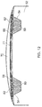
- Figure 12 shows the mould part 52 following a further step of the second manufacturing method.
- this step further tapes or layers of pre-preg 70 are laid in and on the mould part 52 over the initial layers 71 (which will now become incorporated into the component pre-preg layers 70) to form the shape of the composite component.
- these tapes or layers will be applied in a conventional manner in different directions, as described above in connection with Figure 6 .
- the pre-preg 70 is then cured in a conventional manner, typically in an autoclave, to form the component.
- the first ends 64 and second ends 66 of the pins 62 will become securely fixed, respectively within the pre-preg 70 forming the component and within the pre-preg 60 forming the datum features.
- the pins are used to identify and locate the positions of the original datum features, when a component requires repair or other attention.
Landscapes
- Engineering & Computer Science (AREA)
- Mechanical Engineering (AREA)
- Chemical & Material Sciences (AREA)
- Composite Materials (AREA)
- Moulding By Coating Moulds (AREA)
Abstract
Description
- This disclosure relates to the manufacture of composite components, and in particular to the provision of datum features on such components.
- It is known to provide reference or datum features on components during their manufacture, so that manufacturing operations can be carried out relative to a known and stable position or so that the component can be secured in a jig or fixture in a known relationship to a machine tool. Once all the manufacturing operations are completed, the datum feature is typically machined away if it does not form an integral part of the completed component.
- A known arrangement for providing datum features on a composite component is illustrated in
Figure 1 . - The component, which in this arrangement is a
fan blade 12 for a gas turbine engine, has (in its final form) anaerofoil portion 14 and aroot portion 16. It also hasdatum features Datum feature 18 has ahole 22 drilled through it, anddatum feature 20 has mutuallyperpendicular faces - The
component 12 is manufactured by a known method, such as tape laying in which tapes of reinforcing fibres pre-impregnated with partially-cured resin ("pre-preg") are laid within a mould to build up the component. Typically, successive layers of tapes are laid at different angles to provide the desired material properties in the final component. Twoexample tapes Figure 1 ; similar tapes are laid across the whole extent of theblade 12. Once the tape laying is complete, optionally an initial trim is made, and the mould is closed and the composite material is consolidated and cured in the conventional manner. - To facilitate the inclusion of the datum features 18, 20 in the finished
blade 12 the tapes are laid beyond theedges 36 of the finishedblade 12, and extend as far as thedashed line 38, forming an "overlay region". Once the composite material has been cured, the final shape of the blade 12 (including the 'external' datum features 18, 20) is cut out using a known technique such as waterjet cutting. - A disadvantage of this method of manufacture is that the material in the overlay region is wasted. As well as the wasted cost of this material, additional time is needed during manufacturing because the pre-preg tapes must be laid across a wider area.
- A further disadvantage of this method is that the additional step of drilling a
hole 22 through thedatum feature 18 may reduce confidence in the datum position (because the limitations of the drilling process may make the hole misaligned or inaccurately positioned). - After the subsequent machining operations in the manufacturing process have been performed, the datum features are typically machined away (for example, for the
datum feature 18, along the dotted line 42) to leave only the final shape of theblade 12. This gives rise to a further disadvantage of this method of manufacture, because the positions of the datum features are now irrevocably lost. - This means that in any subsequent operations performed on the blade 12 (for example, in-service inspections or repairs) there are no longer any datum features by which the blade can be located, or by reference to which operations can be carried out relative to the "as manufactured" datum. Features such as the
aerofoil surface 44 or theroot 46 must therefore be used as datum features, which is unsatisfactory because these regions of the blade are subject to unpredictable wear in use. Therefore, confidence in the datum position is reduced and inspection or repair operations must be carried out in a more conservative manner, with greater allowances for errors, to ensure safe margins for future operations. This may lead to unnecessary repairs or to shortened component lives. - It would be desirable to have a method for providing datum features on a component that reduces or overcomes these disadvantages.
- According to a first aspect there is provided a composite component as set out in the claims. According to a second aspect there is provided a method of making a composite component as set out in the claims.
- Embodiments of the invention will now be described in more detail, with reference to the attached drawings, in which
-
Figure 1 is a schematic view illustrating a known manufacturing method for a composite component, as already described; -
Figures 2 to 9 show successive steps in a first method of manufacturing a composite component including datum features. In each ofFigures 2 to 5 , (a) is a sectional side view and (b) is a partial plan view on the arrow A of (a).Figure 9(b) is a partial plan view on the arrow B ofFigure 9(a) ; and -
Figures 10 to 12 show successive steps in a second method of manufacturing a composite component including datum features. In each ofFigures 10 and11 , (a) is a sectional side view and (b) is a partial plan view on the arrow A of (a). - In the drawings, like elements are identified by like reference numbers.
-
Figures 2(a) and 2(b) show alower part 52 of a mould for manufacturing a composite component. The upper part of the mould is not shown. Themould part 52 comprises tworecesses 54; the recesses are in the shape of truncated cones, withangled walls 56 andflat bottoms 58. The mould is of known type, and is made of a material with a thermal coefficient of expansion compatible with the composite material to be used (for example, made from Invar ® or carbon composite). -
Figures 3(a) and 3(b) show themould part 52 following a step of a first manufacturing method.Layers 60 of pre-preg have been laid in eachrecess 54 so as to fill it. After consolidation and curing these layers will form the datum features of the component, as will be further explained below. -
Figure 4(a) shows themould part 52 following a further step of the manufacturing method. In the recess 54', a plurality ofpins 62 have been inserted into thepre-preg layers 60, so that afirst end 64 of each pin protrudes above the surface of thelayers 60 and asecond end 66 of each pin is embedded and engaged in the pre-preg layers. As can be seen inFigure 4(b) , thepins 62 are distributed around the recess 54'. The pins are similar to known pins used for z-pinning (through-thickness reinforcement) of composite structures, and are made, for example, from glass or carbon fibres. It is known to use monolithic pins or pins formed from bundles of fibres; it is also known to use pultruded carbon rods. The diameter of the pins is typically between 0.2 mm and 1.0 mm. The volume ratio of the pins is typically between 0.5% and 4.0%. The number of pins inserted into each recess will depend upon a number of factors, including the size and weight of the component and the number of datum positions (i.e. the complexity of the structure being formed). - In a further step of the manufacturing method,
further pins 62 would be inserted, in a similar manner, into thepre-preg layers 60 inrecess 54". (For simplicity, this disclosure and drawings will describe the steps of the method only with reference to recess 54', but a skilled person will understand that all the steps performed on that recess would in reality also be performed onrecess 54".) -
Figure 5(a) shows themould part 52 following a further step of the manufacturing method. Arelease layer 68 has been laid on thepre-preg layers 60, so as to overlie the recess 54'. It can be seen fromFigure 5(b) that the edge of therelease layer 68 extends beyond the edge (shown as a dashed line) of the recess 54'. The release layer is perforated so that thefirst ends 64 of thepins 62 protrude through therelease layer 68. The release layer is made from a conventional material such as PTFE, PVF or ETFE film (for instance DuPont™ Tedlar ® film) that will not adhere to the composite material during the curing process, but provides sufficient stiction to remain in place. -
Figure 6 shows themould part 52 following a further step of the manufacturing method. In previous steps, as described above,pins 62 have been inserted into thepre-preg layers 60 and release layers have been applied over therecesses 54. In this step, tapes or layers of pre-preg 70 are laid in and on themould part 52 to form the shape of the composite component. Typically, these tapes or layers will be applied in a conventional manner in different directions, in for instance a quasi-isotropic laminate structure (using rules such as diamond rule, as specified in US MIL handbook 17 and other similar treatises) in a similar manner to that shown inFigure 1 . As the tapes or layers are built up, thefirst ends 64 of thepins 62 will become embedded and engaged in the pre-preg 70. - Because there is no need to provide external datum features, the overlay region of the component need not be as large as in the known arrangement shown in
Figure 1 , so less material is wasted in the manufacture of the component. - Once the laying and consolidation of the pre-preg 70 is complete, either the component is vacuum bagged (not shown), or the upper part of the mould (not shown in the drawings) is brought into place and the mould closed. The pre-preg is then cured in a conventional manner, typically in an autoclave, to form the component. During the curing process, the
first ends 64 andsecond ends 66 of thepins 62 will become securely fixed, respectively within the pre-preg 70 forming the component and within the pre-preg 60 forming the datum features. -
Figure 7 shows thecomposite component 74 following curing and removal from the mould. Datum features 76 protrude from the surface of the component, and (as in known arrangements) may be used to establish the position of the blade with respect to an absolute reference point for subsequent machining or finishing operations. - Once all the manufacturing operations have been completed, the datum features 76 must be removed to make the
composite component 74 ready for use. As shown inFigure 8 , the presence of the release layers 68 permits the datum feature 76' to be removed by applying a force in the direction shown by thearrow 80, so as to shear thepins 62. The first ends 64 of the pins remain in thecomposite component 74, and the second ends 66 of thepins 62 remain within the datum feature 76'. - The datum feature 76' can now be recycled or disposed of. As the datum feature 76' was formed and cured with the component it can be used as a process control or to manufacture test pieces for destructive testing. Additional parts made together with the original for NDE or for test purposes are in the trade called "carriers"; this saves having to take production parts for destructive (cut-up) testing to validate the production process, thus reducing the need to periodically destructively test completed components to assure process compliance, such as correct curing.
-
Figure 9(a) shows a completedcomposite component 74, following the removal of the datum features. The first ends 64 of thepins 62 remain in thecomposite component 74, and, as shown inFigure 9(b) , are visible at the surface of thecomposite component 74. - The composite component can then move on for finishing and protection to be applied. Typically this requires a UV protection layer, moisture barrier, colourant/paint, and impact/erosion protection layer. Depending upon the product, all these features may be provided by a single material layer.
- When subsequent operations (for example, inspection or repair operations) are to be performed on the composite component following a period in service, the pin positions can be detected and used to determine the precise positions of the original datum features. The position of the blade can therefore be determined with respect to the same reference points used during its manufacture, and the subsequent operations can be performed relative to the original datum positions. This gives greater confidence and accuracy in the operations.
- Before a repair operation can commence, normally the protective layer is removed; this allows access to the pinned area for detection, either: visibly; by CT scan; or by surface probe. Repairs or measurements can then be made relative to the original manufacturing datum. Knowing the position of the datum gives a reference to measure how much wear or distortion has taken place and where it has occurred.
- In a second manufacturing method, illustrated in
Figures 10 to 12 , a different sequence of steps is used to manufacture thecomposite component 74. - The first steps of the second manufacturing method are the same as those shown in
Figures 2 and3 , and already described. -
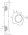
Figure 10(a) shows themould part 52 following a further step of the second manufacturing method. Arelease layer 68 has been laid on thepre-preg layers 60, so as to overlie the recess 54'. It can be seen fromFigure 10(b) that the edge of the release layer 68 (shown as a dashed line) extends beyond the edge of the recess 54'. The first few pre-preg layers 71 of the component have also been laid. These layers are the first that define the component and also serve to keep therelease layer 68 in place. -
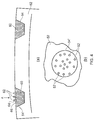
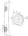
Figure 11 (a) shows themould part 52 following a further step of the second manufacturing method. In the recess 54', a plurality ofpins 62 have been inserted into thepre-preg layers 60 through thefirst layers 71 of the component and therelease layer 68, so that afirst end 64 of each pin is embedded and engaged in thefirst layers 71 and asecond end 66 of each pin is embedded and engaged in thepre-preg layers 60 in the recess 54'. As can be seen inFigure 11(b) , thepins 62 are distributed around the recess 54'. The pins are of the same type and material as those already described in connection withFigure 4 . -
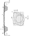
Figure 12 shows themould part 52 following a further step of the second manufacturing method. In this step, further tapes or layers ofpre-preg 70 are laid in and on themould part 52 over the initial layers 71 (which will now become incorporated into the component pre-preg layers 70) to form the shape of the composite component. Typically, these tapes or layers will be applied in a conventional manner in different directions, as described above in connection withFigure 6 . - Once the laying and consolidation of the pre-preg 70 is complete, either the component is vacuum bagged (not shown), or the upper part of the mould (not shown in the drawings) is brought into place and the mould closed. The pre-preg is then cured in a conventional manner, typically in an autoclave, to form the component. During the curing process, the first ends 64 and second ends 66 of the
pins 62 will become securely fixed, respectively within the pre-preg 70 forming the component and within the pre-preg 60 forming the datum features. - The remaining steps in the second manufacturing method are identical to the corresponding steps in the first manufacturing method, as shown in
Figures 7 to 9 and already described. - An advantage of this second manufacturing method is that the release layer need not be perforated, because the action of inserting the pins will make holes through it, whilst the first few layers of the composite hold it in place. A composite consolidation step may take place prior to the insertion of the pins.
- The pins are used to identify and locate the positions of the original datum features, when a component requires repair or other attention.
Claims (7)
- A composite component (74) including a component body and a datum feature (76), the datum feature projecting in a first direction from a surface of the component body, the component further including a plurality of pins (62) extending generally in the first direction so that a first end (64) of each pin is engaged in the component body and a second end (66) of each pin is engaged in the datum feature, the datum feature being removable from the component so as to leave the first ends of the pins engaged with the component body.
- The component of claim 1, in which the datum feature is in the form of a truncated cone or truncated pyramid.
- The component of claim 1 or claim 2, in which a release layer (68) is provided between the component body and the datum feature to form a release plane.
- The component of any one of the preceding claims, in which the datum feature is removable by shearing or fracturing the pins along the release plane.
- The component of any one of the preceding claims, in which after the removal of the datum feature the positions of the first ends of the pins may be used to determine the position in which the datum feature was located.
- A method of making a composite component (74) including a datum feature (76), the method comprising the steps of:providing a mould (52) for forming a composite component, the mould having a recess (54) for forming a datum feature;filling the recess with pre-preg material (60);inserting a plurality of pins (62) into the pre-preg material so that a first end (64) of each pin protrudes from the pre-preg material and a second end (66) of each pin is engaged in the pre-preg material;applying a release layer (68) to the pre-preg material so that the first ends of the pins protrude through the release layer;applying at least one further pre-preg layer (70) to form the composite component;performing a moulding operation to form the component in the mould, so that the first ends of the pins become engaged with the component;curing the component.
- A method of making a composite component (74) including a datum feature (76), the method comprising the steps of:providing a mould (52) for forming a composite component, the mould having a recess (54) for forming a datum feature;filling the recess with pre-preg material (60);applying a release layer (68) to the pre-preg material;applying at least one pre-preg layer (71) above the release layer;inserting a plurality of pins (62) through the pre-preg layer and release layer and into the pre-preg material so that a first end (64) of each pin protrudes from the pre-preg layer and a second end (66) of each pin is engaged in the pre-preg material;applying at least one further pre-preg layer (70) to form the composite component;performing a moulding operation to form the component in the mould, so that the first ends of the pins become engaged with the component;curing the component.
Applications Claiming Priority (1)
| Application Number | Priority Date | Filing Date | Title |
|---|---|---|---|
| GBGB1514139.3A GB201514139D0 (en) | 2015-08-11 | 2015-08-11 | A datum feature for a composite component |
Publications (2)
| Publication Number | Publication Date |
|---|---|
| EP3144129A1 true EP3144129A1 (en) | 2017-03-22 |
| EP3144129B1 EP3144129B1 (en) | 2021-06-23 |
Family
ID=54200503
Family Applications (1)
| Application Number | Title | Priority Date | Filing Date |
|---|---|---|---|
| EP16182539.3A Active EP3144129B1 (en) | 2015-08-11 | 2016-08-03 | A datum feature for a composite component |
Country Status (3)
| Country | Link |
|---|---|
| US (1) | US10099433B2 (en) |
| EP (1) | EP3144129B1 (en) |
| GB (1) | GB201514139D0 (en) |
Families Citing this family (2)
| Publication number | Priority date | Publication date | Assignee | Title |
|---|---|---|---|---|
| AT521672B1 (en) * | 2018-09-10 | 2022-10-15 | Facc Ag | Method of manufacturing a fiber-plastic composite reference body and test method |
| US12391010B2 (en) * | 2023-01-13 | 2025-08-19 | Rtx Corporation | Methods of manufacture for composite blades |
Citations (8)
| Publication number | Priority date | Publication date | Assignee | Title |
|---|---|---|---|---|
| FR2312673A1 (en) * | 1975-05-29 | 1976-12-24 | Gen Electric | VARIABLE STEP DAWN ASSEMBLY DEVICE |
| US4084922A (en) * | 1976-12-27 | 1978-04-18 | Electric Power Research Institute, Inc. | Turbine rotor with pin mounted ceramic turbine blades |
| FR2697284A1 (en) * | 1992-10-27 | 1994-04-29 | Europ Propulsion | Method for manufacturing a turbine wheel with inserted blades and wheel obtained by the method. |
| US5609953A (en) * | 1994-06-02 | 1997-03-11 | Nippon Planning Co., Ltd. | Plastic molded articles having resin fibers dispersed therein |
| US20050064134A1 (en) * | 2003-04-24 | 2005-03-24 | Brantley Jerry W. | Apparatus, system, and method of joining structural components with a tapered tension bond joint |
| US20120291585A1 (en) * | 2010-10-22 | 2012-11-22 | Nsk, Ltd. | Steering column support apparatus and assembly method |
| EP2642076A2 (en) * | 2012-03-19 | 2013-09-25 | General Electric Company | Connecting system for metal components and cmc components, a turbine blade retaining system and a rotating component retaining system |
| US20140234098A1 (en) * | 2013-02-17 | 2014-08-21 | United Technologies Corporation | Turbine case retention hook with insert |
Family Cites Families (4)
| Publication number | Priority date | Publication date | Assignee | Title |
|---|---|---|---|---|
| US5876540A (en) * | 1996-05-31 | 1999-03-02 | The Boeing Company | Joining composites using Z-pinned precured strips |
| US6179567B1 (en) | 1999-08-18 | 2001-01-30 | United Technologies Corporation | Turbomachinery blade or vane with a survivable machining datum |
| KR100932302B1 (en) * | 2007-09-17 | 2009-12-16 | 한국항공우주연구원 | Composite laminated structure reinforced with performance by pinning, composite manufacturing method, device and manufacturing method of the composite laminated structure |
| GB201003592D0 (en) | 2010-03-04 | 2010-04-21 | Rolls Royce Plc | A component comprising a resin matrix |
-
2015
- 2015-08-11 GB GBGB1514139.3A patent/GB201514139D0/en not_active Ceased
-
2016
- 2016-08-03 US US15/227,267 patent/US10099433B2/en active Active
- 2016-08-03 EP EP16182539.3A patent/EP3144129B1/en active Active
Patent Citations (8)
| Publication number | Priority date | Publication date | Assignee | Title |
|---|---|---|---|---|
| FR2312673A1 (en) * | 1975-05-29 | 1976-12-24 | Gen Electric | VARIABLE STEP DAWN ASSEMBLY DEVICE |
| US4084922A (en) * | 1976-12-27 | 1978-04-18 | Electric Power Research Institute, Inc. | Turbine rotor with pin mounted ceramic turbine blades |
| FR2697284A1 (en) * | 1992-10-27 | 1994-04-29 | Europ Propulsion | Method for manufacturing a turbine wheel with inserted blades and wheel obtained by the method. |
| US5609953A (en) * | 1994-06-02 | 1997-03-11 | Nippon Planning Co., Ltd. | Plastic molded articles having resin fibers dispersed therein |
| US20050064134A1 (en) * | 2003-04-24 | 2005-03-24 | Brantley Jerry W. | Apparatus, system, and method of joining structural components with a tapered tension bond joint |
| US20120291585A1 (en) * | 2010-10-22 | 2012-11-22 | Nsk, Ltd. | Steering column support apparatus and assembly method |
| EP2642076A2 (en) * | 2012-03-19 | 2013-09-25 | General Electric Company | Connecting system for metal components and cmc components, a turbine blade retaining system and a rotating component retaining system |
| US20140234098A1 (en) * | 2013-02-17 | 2014-08-21 | United Technologies Corporation | Turbine case retention hook with insert |
Also Published As
| Publication number | Publication date |
|---|---|
| EP3144129B1 (en) | 2021-06-23 |
| GB201514139D0 (en) | 2015-09-23 |
| US10099433B2 (en) | 2018-10-16 |
| US20170043541A1 (en) | 2017-02-16 |
Similar Documents
| Publication | Publication Date | Title |
|---|---|---|
| EP2210733B1 (en) | Method for manufacturing a composite component with a 3D woven structure | |
| EP2724847B1 (en) | System and method of constructing composite structures | |
| EP3289309B1 (en) | Methods and systems for bonding | |
| JP6701193B2 (en) | How to check the preform position in the mold | |
| US8685297B2 (en) | Method for the manufacture of a fiber-composite component and fiber-composite component manufactured according to this method | |
| CN101169382B (en) | Manufacturing process for a pilot blade made of composite material | |
| EP3274159B1 (en) | Repair of wind turbine components | |
| EP2800874B1 (en) | Method for checking cooling holes of a gas turbine blade | |
| EP2977192B1 (en) | Fabric jacketed unidirectional noodle and its method of construction | |
| US10377091B2 (en) | Methods for forming a composite blade stiffener and facilitating application of barely visible impact damage treatments | |
| US20160263845A1 (en) | Method for repairing sandwich panels made of composite materials involving the creation of a core or of a mould using stereolithography | |
| EP2982500A1 (en) | Composite structure and method of forming thereof | |
| EP3144129B1 (en) | A datum feature for a composite component | |
| US10239223B2 (en) | Cutting table for cutting a fiber preform obtained by three-dimensional weaving, and a cutting method using such a table | |
| EP3062999B1 (en) | Method for manufacturing hollow reinforcement structures intersecting one another | |
| US11440277B2 (en) | Method of repairing composite sandwich panels | |
| EP2955005B1 (en) | A composite structure and a method of fabricating the same | |
| EP3159655A1 (en) | Profilometry inspection systems and methods for spar caps of composite wind turbine blades | |
| EP3040191A1 (en) | Method for manufacturing fillers of composite material | |
| US10059068B2 (en) | Composite structure and method of forming thereof | |
| Head | Flight Test of a Composite Multi-Tubular Spar Main Rotor Blade on the AH-1G Helicopter. Volume II. Cost Estimates and Process Specifications. |
Legal Events
| Date | Code | Title | Description |
|---|---|---|---|
| PUAI | Public reference made under article 153(3) epc to a published international application that has entered the european phase |
Free format text: ORIGINAL CODE: 0009012 |
|
| STAA | Information on the status of an ep patent application or granted ep patent |
Free format text: STATUS: THE APPLICATION HAS BEEN PUBLISHED |
|
| AK | Designated contracting states |
Kind code of ref document: A1 Designated state(s): AL AT BE BG CH CY CZ DE DK EE ES FI FR GB GR HR HU IE IS IT LI LT LU LV MC MK MT NL NO PL PT RO RS SE SI SK SM TR |
|
| AX | Request for extension of the european patent |
Extension state: BA ME |
|
| STAA | Information on the status of an ep patent application or granted ep patent |
Free format text: STATUS: REQUEST FOR EXAMINATION WAS MADE |
|
| 17P | Request for examination filed |
Effective date: 20170921 |
|
| RBV | Designated contracting states (corrected) |
Designated state(s): AL AT BE BG CH CY CZ DE DK EE ES FI FR GB GR HR HU IE IS IT LI LT LU LV MC MK MT NL NO PL PT RO RS SE SI SK SM TR |
|
| RAP1 | Party data changed (applicant data changed or rights of an application transferred) |
Owner name: ROLLS-ROYCE PLC |
|
| REG | Reference to a national code |
Ref country code: DE Ref legal event code: R079 Ref document number: 602016059588 Country of ref document: DE Free format text: PREVIOUS MAIN CLASS: B29C0070540000 Ipc: B29C0070340000 |
|
| GRAP | Despatch of communication of intention to grant a patent |
Free format text: ORIGINAL CODE: EPIDOSNIGR1 |
|
| STAA | Information on the status of an ep patent application or granted ep patent |
Free format text: STATUS: GRANT OF PATENT IS INTENDED |
|
| RIC1 | Information provided on ipc code assigned before grant |
Ipc: B29C 70/34 20060101AFI20210319BHEP Ipc: B29C 70/54 20060101ALI20210319BHEP Ipc: B29C 33/12 20060101ALI20210319BHEP Ipc: B29C 65/00 20060101ALI20210319BHEP Ipc: B29C 70/86 20060101ALI20210319BHEP Ipc: B29K 105/08 20060101ALI20210319BHEP Ipc: B29K 307/04 20060101ALI20210319BHEP Ipc: B29L 31/08 20060101ALI20210319BHEP |
|
| GRAS | Grant fee paid |
Free format text: ORIGINAL CODE: EPIDOSNIGR3 |
|
| INTG | Intention to grant announced |
Effective date: 20210420 |
|
| GRAA | (expected) grant |
Free format text: ORIGINAL CODE: 0009210 |
|
| STAA | Information on the status of an ep patent application or granted ep patent |
Free format text: STATUS: THE PATENT HAS BEEN GRANTED |
|
| AK | Designated contracting states |
Kind code of ref document: B1 Designated state(s): AL AT BE BG CH CY CZ DE DK EE ES FI FR GB GR HR HU IE IS IT LI LT LU LV MC MK MT NL NO PL PT RO RS SE SI SK SM TR |
|
| REG | Reference to a national code |
Ref country code: GB Ref legal event code: FG4D |
|
| REG | Reference to a national code |
Ref country code: CH Ref legal event code: EP |
|
| REG | Reference to a national code |
Ref country code: DE Ref legal event code: R096 Ref document number: 602016059588 Country of ref document: DE Ref country code: AT Ref legal event code: REF Ref document number: 1403935 Country of ref document: AT Kind code of ref document: T Effective date: 20210715 |
|
| REG | Reference to a national code |
Ref country code: IE Ref legal event code: FG4D |
|
| REG | Reference to a national code |
Ref country code: LT Ref legal event code: MG9D |
|
| PG25 | Lapsed in a contracting state [announced via postgrant information from national office to epo] |
Ref country code: BG Free format text: LAPSE BECAUSE OF FAILURE TO SUBMIT A TRANSLATION OF THE DESCRIPTION OR TO PAY THE FEE WITHIN THE PRESCRIBED TIME-LIMIT Effective date: 20210923 Ref country code: HR Free format text: LAPSE BECAUSE OF FAILURE TO SUBMIT A TRANSLATION OF THE DESCRIPTION OR TO PAY THE FEE WITHIN THE PRESCRIBED TIME-LIMIT Effective date: 20210623 Ref country code: FI Free format text: LAPSE BECAUSE OF FAILURE TO SUBMIT A TRANSLATION OF THE DESCRIPTION OR TO PAY THE FEE WITHIN THE PRESCRIBED TIME-LIMIT Effective date: 20210623 Ref country code: LT Free format text: LAPSE BECAUSE OF FAILURE TO SUBMIT A TRANSLATION OF THE DESCRIPTION OR TO PAY THE FEE WITHIN THE PRESCRIBED TIME-LIMIT Effective date: 20210623 |
|
| PGFP | Annual fee paid to national office [announced via postgrant information from national office to epo] |
Ref country code: FR Payment date: 20210830 Year of fee payment: 6 |
|
| REG | Reference to a national code |
Ref country code: AT Ref legal event code: MK05 Ref document number: 1403935 Country of ref document: AT Kind code of ref document: T Effective date: 20210623 |
|
| PG25 | Lapsed in a contracting state [announced via postgrant information from national office to epo] |
Ref country code: GR Free format text: LAPSE BECAUSE OF FAILURE TO SUBMIT A TRANSLATION OF THE DESCRIPTION OR TO PAY THE FEE WITHIN THE PRESCRIBED TIME-LIMIT Effective date: 20210924 Ref country code: LV Free format text: LAPSE BECAUSE OF FAILURE TO SUBMIT A TRANSLATION OF THE DESCRIPTION OR TO PAY THE FEE WITHIN THE PRESCRIBED TIME-LIMIT Effective date: 20210623 Ref country code: SE Free format text: LAPSE BECAUSE OF FAILURE TO SUBMIT A TRANSLATION OF THE DESCRIPTION OR TO PAY THE FEE WITHIN THE PRESCRIBED TIME-LIMIT Effective date: 20210623 Ref country code: RS Free format text: LAPSE BECAUSE OF FAILURE TO SUBMIT A TRANSLATION OF THE DESCRIPTION OR TO PAY THE FEE WITHIN THE PRESCRIBED TIME-LIMIT Effective date: 20210623 Ref country code: NO Free format text: LAPSE BECAUSE OF FAILURE TO SUBMIT A TRANSLATION OF THE DESCRIPTION OR TO PAY THE FEE WITHIN THE PRESCRIBED TIME-LIMIT Effective date: 20210923 |
|
| PGFP | Annual fee paid to national office [announced via postgrant information from national office to epo] |
Ref country code: GB Payment date: 20210826 Year of fee payment: 6 Ref country code: DE Payment date: 20210827 Year of fee payment: 6 |
|
| REG | Reference to a national code |
Ref country code: NL Ref legal event code: MP Effective date: 20210623 |
|
| PG25 | Lapsed in a contracting state [announced via postgrant information from national office to epo] |
Ref country code: SM Free format text: LAPSE BECAUSE OF FAILURE TO SUBMIT A TRANSLATION OF THE DESCRIPTION OR TO PAY THE FEE WITHIN THE PRESCRIBED TIME-LIMIT Effective date: 20210623 Ref country code: SK Free format text: LAPSE BECAUSE OF FAILURE TO SUBMIT A TRANSLATION OF THE DESCRIPTION OR TO PAY THE FEE WITHIN THE PRESCRIBED TIME-LIMIT Effective date: 20210623 Ref country code: CZ Free format text: LAPSE BECAUSE OF FAILURE TO SUBMIT A TRANSLATION OF THE DESCRIPTION OR TO PAY THE FEE WITHIN THE PRESCRIBED TIME-LIMIT Effective date: 20210623 Ref country code: EE Free format text: LAPSE BECAUSE OF FAILURE TO SUBMIT A TRANSLATION OF THE DESCRIPTION OR TO PAY THE FEE WITHIN THE PRESCRIBED TIME-LIMIT Effective date: 20210623 Ref country code: AT Free format text: LAPSE BECAUSE OF FAILURE TO SUBMIT A TRANSLATION OF THE DESCRIPTION OR TO PAY THE FEE WITHIN THE PRESCRIBED TIME-LIMIT Effective date: 20210623 Ref country code: NL Free format text: LAPSE BECAUSE OF FAILURE TO SUBMIT A TRANSLATION OF THE DESCRIPTION OR TO PAY THE FEE WITHIN THE PRESCRIBED TIME-LIMIT Effective date: 20210623 Ref country code: RO Free format text: LAPSE BECAUSE OF FAILURE TO SUBMIT A TRANSLATION OF THE DESCRIPTION OR TO PAY THE FEE WITHIN THE PRESCRIBED TIME-LIMIT Effective date: 20210623 Ref country code: PT Free format text: LAPSE BECAUSE OF FAILURE TO SUBMIT A TRANSLATION OF THE DESCRIPTION OR TO PAY THE FEE WITHIN THE PRESCRIBED TIME-LIMIT Effective date: 20211025 Ref country code: ES Free format text: LAPSE BECAUSE OF FAILURE TO SUBMIT A TRANSLATION OF THE DESCRIPTION OR TO PAY THE FEE WITHIN THE PRESCRIBED TIME-LIMIT Effective date: 20210623 |
|
| PG25 | Lapsed in a contracting state [announced via postgrant information from national office to epo] |
Ref country code: PL Free format text: LAPSE BECAUSE OF FAILURE TO SUBMIT A TRANSLATION OF THE DESCRIPTION OR TO PAY THE FEE WITHIN THE PRESCRIBED TIME-LIMIT Effective date: 20210623 |
|
| REG | Reference to a national code |
Ref country code: DE Ref legal event code: R097 Ref document number: 602016059588 Country of ref document: DE |
|
| REG | Reference to a national code |
Ref country code: CH Ref legal event code: PL |
|
| PG25 | Lapsed in a contracting state [announced via postgrant information from national office to epo] |
Ref country code: MC Free format text: LAPSE BECAUSE OF FAILURE TO SUBMIT A TRANSLATION OF THE DESCRIPTION OR TO PAY THE FEE WITHIN THE PRESCRIBED TIME-LIMIT Effective date: 20210623 |
|
| REG | Reference to a national code |
Ref country code: BE Ref legal event code: MM Effective date: 20210831 |
|
| PG25 | Lapsed in a contracting state [announced via postgrant information from national office to epo] |
Ref country code: LI Free format text: LAPSE BECAUSE OF NON-PAYMENT OF DUE FEES Effective date: 20210831 Ref country code: DK Free format text: LAPSE BECAUSE OF FAILURE TO SUBMIT A TRANSLATION OF THE DESCRIPTION OR TO PAY THE FEE WITHIN THE PRESCRIBED TIME-LIMIT Effective date: 20210623 Ref country code: CH Free format text: LAPSE BECAUSE OF NON-PAYMENT OF DUE FEES Effective date: 20210831 |
|
| PLBE | No opposition filed within time limit |
Free format text: ORIGINAL CODE: 0009261 |
|
| STAA | Information on the status of an ep patent application or granted ep patent |
Free format text: STATUS: NO OPPOSITION FILED WITHIN TIME LIMIT |
|
| 26N | No opposition filed |
Effective date: 20220324 |
|
| PG25 | Lapsed in a contracting state [announced via postgrant information from national office to epo] |
Ref country code: LU Free format text: LAPSE BECAUSE OF NON-PAYMENT OF DUE FEES Effective date: 20210803 Ref country code: AL Free format text: LAPSE BECAUSE OF FAILURE TO SUBMIT A TRANSLATION OF THE DESCRIPTION OR TO PAY THE FEE WITHIN THE PRESCRIBED TIME-LIMIT Effective date: 20210623 |
|
| PG25 | Lapsed in a contracting state [announced via postgrant information from national office to epo] |
Ref country code: IT Free format text: LAPSE BECAUSE OF FAILURE TO SUBMIT A TRANSLATION OF THE DESCRIPTION OR TO PAY THE FEE WITHIN THE PRESCRIBED TIME-LIMIT Effective date: 20210623 Ref country code: IE Free format text: LAPSE BECAUSE OF NON-PAYMENT OF DUE FEES Effective date: 20210803 Ref country code: BE Free format text: LAPSE BECAUSE OF NON-PAYMENT OF DUE FEES Effective date: 20210831 |
|
| REG | Reference to a national code |
Ref country code: DE Ref legal event code: R119 Ref document number: 602016059588 Country of ref document: DE |
|
| GBPC | Gb: european patent ceased through non-payment of renewal fee |
Effective date: 20220803 |
|
| PG25 | Lapsed in a contracting state [announced via postgrant information from national office to epo] |
Ref country code: HU Free format text: LAPSE BECAUSE OF FAILURE TO SUBMIT A TRANSLATION OF THE DESCRIPTION OR TO PAY THE FEE WITHIN THE PRESCRIBED TIME-LIMIT; INVALID AB INITIO Effective date: 20160803 |
|
| PG25 | Lapsed in a contracting state [announced via postgrant information from national office to epo] |
Ref country code: CY Free format text: LAPSE BECAUSE OF FAILURE TO SUBMIT A TRANSLATION OF THE DESCRIPTION OR TO PAY THE FEE WITHIN THE PRESCRIBED TIME-LIMIT Effective date: 20210623 |
|
| PG25 | Lapsed in a contracting state [announced via postgrant information from national office to epo] |
Ref country code: FR Free format text: LAPSE BECAUSE OF NON-PAYMENT OF DUE FEES Effective date: 20220831 Ref country code: DE Free format text: LAPSE BECAUSE OF NON-PAYMENT OF DUE FEES Effective date: 20230301 |
|
| PG25 | Lapsed in a contracting state [announced via postgrant information from national office to epo] |
Ref country code: GB Free format text: LAPSE BECAUSE OF NON-PAYMENT OF DUE FEES Effective date: 20220803 |
|
| PG25 | Lapsed in a contracting state [announced via postgrant information from national office to epo] |
Ref country code: MK Free format text: LAPSE BECAUSE OF FAILURE TO SUBMIT A TRANSLATION OF THE DESCRIPTION OR TO PAY THE FEE WITHIN THE PRESCRIBED TIME-LIMIT Effective date: 20210623 |
|
| PG25 | Lapsed in a contracting state [announced via postgrant information from national office to epo] |
Ref country code: MT Free format text: LAPSE BECAUSE OF FAILURE TO SUBMIT A TRANSLATION OF THE DESCRIPTION OR TO PAY THE FEE WITHIN THE PRESCRIBED TIME-LIMIT Effective date: 20210623 |
|
| PG25 | Lapsed in a contracting state [announced via postgrant information from national office to epo] |
Ref country code: TR Free format text: LAPSE BECAUSE OF FAILURE TO SUBMIT A TRANSLATION OF THE DESCRIPTION OR TO PAY THE FEE WITHIN THE PRESCRIBED TIME-LIMIT Effective date: 20210623 |