EP3144107A1 - A wearable manufacturing assistance device - Google Patents
A wearable manufacturing assistance device Download PDFInfo
- Publication number
- EP3144107A1 EP3144107A1 EP15185353.8A EP15185353A EP3144107A1 EP 3144107 A1 EP3144107 A1 EP 3144107A1 EP 15185353 A EP15185353 A EP 15185353A EP 3144107 A1 EP3144107 A1 EP 3144107A1
- Authority
- EP
- European Patent Office
- Prior art keywords
- arm member
- body unit
- manufacturing
- assistance device
- tool
- Prior art date
- Legal status (The legal status is an assumption and is not a legal conclusion. Google has not performed a legal analysis and makes no representation as to the accuracy of the status listed.)
- Withdrawn
Links
- 238000004519 manufacturing process Methods 0.000 title claims abstract description 96
- 239000000463 material Substances 0.000 claims description 28
- 239000004698 Polyethylene Substances 0.000 claims description 6
- 230000007935 neutral effect Effects 0.000 claims description 5
- 102100040287 GTP cyclohydrolase 1 feedback regulatory protein Human genes 0.000 claims description 4
- 101710185324 GTP cyclohydrolase 1 feedback regulatory protein Proteins 0.000 claims description 4
- 239000004696 Poly ether ether ketone Substances 0.000 claims description 4
- XAGFODPZIPBFFR-UHFFFAOYSA-N aluminium Chemical compound [Al] XAGFODPZIPBFFR-UHFFFAOYSA-N 0.000 claims description 4
- 229910052782 aluminium Inorganic materials 0.000 claims description 4
- 239000004918 carbon fiber reinforced polymer Substances 0.000 claims description 4
- 239000006260 foam Substances 0.000 claims description 4
- 229920002530 polyetherether ketone Polymers 0.000 claims description 4
- -1 polyethylene Polymers 0.000 claims description 4
- 229920000573 polyethylene Polymers 0.000 claims description 4
- 235000017166 Bambusa arundinacea Nutrition 0.000 claims description 2
- 235000017491 Bambusa tulda Nutrition 0.000 claims description 2
- 241001330002 Bambuseae Species 0.000 claims description 2
- 235000015334 Phyllostachys viridis Nutrition 0.000 claims description 2
- 239000011425 bamboo Substances 0.000 claims description 2
- 239000011159 matrix material Substances 0.000 claims description 2
- 239000002952 polymeric resin Substances 0.000 claims description 2
- 229920003002 synthetic resin Polymers 0.000 claims description 2
- 239000002023 wood Substances 0.000 claims description 2
- 230000001419 dependent effect Effects 0.000 claims 1
- 238000010276 construction Methods 0.000 abstract description 8
- 239000002131 composite material Substances 0.000 description 4
- 239000000835 fiber Substances 0.000 description 3
- 239000006261 foam material Substances 0.000 description 3
- 210000003127 knee Anatomy 0.000 description 3
- 239000004033 plastic Substances 0.000 description 3
- 229920003023 plastic Polymers 0.000 description 3
- 210000002414 leg Anatomy 0.000 description 2
- 229910001008 7075 aluminium alloy Inorganic materials 0.000 description 1
- 229910000838 Al alloy Inorganic materials 0.000 description 1
- 229910045601 alloy Inorganic materials 0.000 description 1
- 239000000956 alloy Substances 0.000 description 1
- 230000002457 bidirectional effect Effects 0.000 description 1
- 238000009413 insulation Methods 0.000 description 1
Images

Classifications
-
- B—PERFORMING OPERATIONS; TRANSPORTING
- B25—HAND TOOLS; PORTABLE POWER-DRIVEN TOOLS; MANIPULATORS
- B25H—WORKSHOP EQUIPMENT, e.g. FOR MARKING-OUT WORK; STORAGE MEANS FOR WORKSHOPS
- B25H1/00—Work benches; Portable stands or supports for positioning portable tools or work to be operated on thereby
- B25H1/0021—Stands, supports or guiding devices for positioning portable tools or for securing them to the work
- B25H1/0028—Tool balancers
-
- F—MECHANICAL ENGINEERING; LIGHTING; HEATING; WEAPONS; BLASTING
- F16—ENGINEERING ELEMENTS AND UNITS; GENERAL MEASURES FOR PRODUCING AND MAINTAINING EFFECTIVE FUNCTIONING OF MACHINES OR INSTALLATIONS; THERMAL INSULATION IN GENERAL
- F16M—FRAMES, CASINGS OR BEDS OF ENGINES, MACHINES OR APPARATUS, NOT SPECIFIC TO ENGINES, MACHINES OR APPARATUS PROVIDED FOR ELSEWHERE; STANDS; SUPPORTS
- F16M13/00—Other supports for positioning apparatus or articles; Means for steadying hand-held apparatus or articles
- F16M13/04—Other supports for positioning apparatus or articles; Means for steadying hand-held apparatus or articles for supporting on, or holding steady relative to, a person, e.g. by chains, e.g. rifle butt or pistol grip supports, supports attached to the chest or head
-
- A—HUMAN NECESSITIES
- A45—HAND OR TRAVELLING ARTICLES
- A45F—TRAVELLING OR CAMP EQUIPMENT: SACKS OR PACKS CARRIED ON THE BODY
- A45F3/00—Travelling or camp articles; Sacks or packs carried on the body
- A45F3/14—Carrying-straps; Pack-carrying harnesses
- A45F2003/146—Pack-carrying harnesses
-
- B—PERFORMING OPERATIONS; TRANSPORTING
- B25—HAND TOOLS; PORTABLE POWER-DRIVEN TOOLS; MANIPULATORS
- B25D—PERCUSSIVE TOOLS
- B25D17/00—Details of, or accessories for, portable power-driven percussive tools
- B25D17/28—Supports; Devices for holding power-driven percussive tools in working position
-
- F—MECHANICAL ENGINEERING; LIGHTING; HEATING; WEAPONS; BLASTING
- F16—ENGINEERING ELEMENTS AND UNITS; GENERAL MEASURES FOR PRODUCING AND MAINTAINING EFFECTIVE FUNCTIONING OF MACHINES OR INSTALLATIONS; THERMAL INSULATION IN GENERAL
- F16M—FRAMES, CASINGS OR BEDS OF ENGINES, MACHINES OR APPARATUS, NOT SPECIFIC TO ENGINES, MACHINES OR APPARATUS PROVIDED FOR ELSEWHERE; STANDS; SUPPORTS
- F16M11/00—Stands or trestles as supports for apparatus or articles placed thereon ; Stands for scientific apparatus such as gravitational force meters
- F16M11/20—Undercarriages with or without wheels
- F16M11/2007—Undercarriages with or without wheels comprising means allowing pivoting adjustment
- F16M11/2014—Undercarriages with or without wheels comprising means allowing pivoting adjustment around a vertical axis
-
- G—PHYSICS
- G02—OPTICS
- G02B—OPTICAL ELEMENTS, SYSTEMS OR APPARATUS
- G02B7/00—Mountings, adjusting means, or light-tight connections, for optical elements
Definitions
- the present invention relates to a wearable manufacturing assistance device for supporting a manufacturing tool, in particular for supporting a technician in holding a manufacturing tool during manufacture of an aircraft or spacecraft.
- the manufacturing assistance device comprises a body unit and an arm member.
- the body unit includes fastening means for fastening the body unit to the back of a technician in a normal, intended wearing position.
- the arm member has an elongate form and preferably a circular, elliptic, or polygonal cross section with a preferably constant diameter along its length. However, the diameter may also change along its length, either continuously or gradually, so that various sections with different diameters are provided.
- the arm member has an attachment end attached to the body unit, and a tool end opposite to the attachment end. At the tool end the arm member comprises a mounting device for mounting a manufacturing tool to the arm member.
- third arm devices or zero-g arm devices comprising an arm member for holding a manufacturing tool, such as a drill, in order to support a technician in holding the tool, especially when the tool has a considerable weight and has to be held by the technician over a longer period of time.
- the arm member can be mounted either to the technical device which is manufactured itself, or to a separate support stand.
- the arm member might also be mounted to a body unit which is fastened to the body of a technician, so that the technician can carry the arm member with him and is flexible with respect to his position along the technical device to be manufactured.
- Such third arm devices or zero-g arm devices which are fastened to the body of a technician are often combined with exoskeletons further supporting the technician in moving his body under the load of the manufacturing tool and the third arm device or zero-g arm device.
- the known manufacturing assistance devices are less practical, since they require a considerable amount of equipment fastened around the torso of the technician, and the arm is mounted to the hip or the chest of the technician and extends from there upwards in front of his body, which is both bulky and disadvantageous for overhead work and work in narrow spaces, in particular when impact between the manufacturing tool or the manufacturing assistance device and structural parts of the aircraft or spacecraft have to be avoided in order not to cause damage on the structural parts.
- the object of the present invention is to provide a wearable manufacturing assistance device which has a possibly simply and slender construction and which is practical specifically for the work overhead and in narrow spaces.
- This object is achieved in that, when the body unit is fastened to the back of a technician in the wearing position and the arm member is preferably in a neutral position where it is in an undeformed, relaxed state, the arm member extends from the attachment end at the body unit over the shoulder and laterally past the head of the technician, so that the tool end is preferably in the view field of the technician without turning or tilting his head, i.e., when looking straight ahead, and within the radius of at least one of his arms.
- the body unit has a top edge which points to the top, i.e., in a vertical direction of the body of a technician above his head, when the body unit is fastened to the back of a technician in the wearing position, and the arm member extends beyond this top edge or is attached to the body unit at this top edge, preferably in a decentral position so that the arm member can proceed over the right or left shoulder of a technician.
- a manufacturing tool can be supported via the body unit which is fastened at the back of the technician and the arm member which extends from the back of the technician over his shoulder to a position in his view field where he holds the manufacturing tool.
- No bulky parts of the manufacturing assistance device extend in front of the torso of the technician or along its lateral sides, so that the technician can easily bend over or work on his knees without being handicapped by the manufacturing assistance device.
- performing overhead work with the manufacturing tool is simplified, because the arm member already holds the manufacturing tool in a position in front of this head or even higher than his head.
- a very simple construction of the manufacturing assistance device is possible, since the position and course of the arm member does not even require a distinct hinge between the tool end and the attachment end in order to work the manufacturing tool.
- the arm member comprises a flexibility that allows it to elastically bend in such a way that the tool end is movable out of a neutral position where the arm member is undeformed or relaxed, within a radius of between 10 and 50 cm, preferably between 20 and 40 cm, most preferred about 30 cm, without the body unit being moved.
- the arm member has a length measured from the top edge of the body unit to the tool end of between 50 and 100 cm, preferably between 65 and 85 cm, most preferred about 75 cm, a diameter of between 1 and 10 cm, preferably between 2 and 5 cm, most preferred about 3 cm, and a material with a Young's modulus of below 5 kN/mm 2 , preferably below 1 kN/mm 2 , further preferably below 0.5 kN/mm 2 , further preferably below 0.1 kN/mm 2 , most preferred below 0.05 kN/mm 2 .
- the manufacturing tool mounted to the mounting device at the tool end of the arm member can be moved against the elasticity of the arm member within a radius required during manufacture.
- the stiffness of the arm member is high enough so that the technician might take away his hands from the manufacturing tool and the manufacturing tool is still held in the area of his view field by the arm member, even when it is bent under the weight of the manufacturing tool.
- the material of the arm member is softer, i.e., has a lower hardness, than aluminum, in particular than typical aluminum alloys used for aircraft structures, such as 7075 aluminum alloys.
- the material of the arm member is also softer than common matrix materials of CFRP and GFRP structures, such as polymer resin.
- the material of the arm member is softer than common plastic material used for the attachment of cables and pipes in a fuselage, such as polyether ether ketone (PEEK) material.
- PEEK polyether ether ketone
- the material of the arm member is softer than typical plastic materials used for the insulation of cables.
- the Shore hardness of the material of the arm member is between 70 and 90, preferably between 75 and 85, most preferred 81. In such a way, the arm member cannot damage any of the structural parts made of aluminum or fiber composite material in, e.g., an aircraft or spacecraft, when the arm member accidently contacts these structural parts.
- the arm member is formed in one piece. That means, the arm member is formed integrally and is not comprised of multiple separate portions which might be connected to one another, e.g., via a hinge.
- the arm member has a very simple construction and does not need to be expensive, and the elasticity of the arm member is provided by the material itself.
- the arm member has a homogeneous stiffness along its length, and preferably a constant diameter. In such a way a very simple construction of the arm member is obtained, and under load a predetermined uniform deflection of the arm member along its length from the attachment end to the tool end can be provided.
- the arm member is formed of a single material.
- the single material within the meaning of the present invention also includes a composite material, in particular a fiber composite material. In such a way a possibly simple construction of the arm member is provided and reliable uniform material properties, such as elasticity, are provided.
- the arm member is formed of multiple components, wherein the components are formed of different materials. In such a way, the elasticity of the arm member can be adapted to the specific requirements.
- the components are detachably connected.
- a modular construction of the arm member is provided, wherein the elasticity of an arm member can be adapted to changing requirements by a respective combination of components with the required stiffness.
- the material of the arm member is chosen from a foam, in particular polyethylene foam, such as PE PF663 of Polyform Kunststofftechnik GmbH & Co. KG, D-31737 Rinteln/Germany, from a CFRP, from a GFRP, or from wood, such as bamboo.
- a foam material has a soft surface so that it cannot cause any damage on the aircraft or spacecraft to be manufactured.
- the body unit is formed of the same material as the arm member, so that a very simple construction of the manufacturing assistance device is obtained.
- the arm member is a first arm member, its attachment end is a first attachment end, its tool end is a first tool end, and its mounting device is a first mounting device.
- the manufacturing assistance device comprises a second arm member, which is preferably constructed similar to the first arm member, and which has a second attachment end attached to the body unit and a second tool end opposite to the second attachment end. At the second tool end a second mounting device for mounting a manufacturing tool to the second arm member is provided.
- Both first and second mounting devices may be connected to the same manufacturing tool or to two separate manufacturing tools. In such a way either one heavy manufacturing tool can be supported by two arm members, or two separate manufacturing tools can be supported at the same time in front of the head of the technician, which might be advantageous when two different manufacturing tools have to be used in an alternating manner.
- an adjustment string is provided which is connected to a first string connector provided at the body unit and to a second string connector provided at the arm member, preferably in such a way that it forms a triangle together with the body unit and the arm member.
- the length of the adjustment string measured between the first string connector and the second string connector, is adjustable, so that the angular position of the arm member relative to the body unit is adjustable, against the restoring force of the flexible arm member.
- the adjustment string is preferably made of a flexible material, in particular a bendable material including plastics.
- the length of the adjustment string between first and second string connectors is adjustable, e.g., by a ratchet mechanism at the first and/or second string connector, or by a ratchet mechanism between two ends of the adjustment string when the adjustment string is doubled, i.e., passed bidirectional.
- a ratchet mechanism at the first and/or second string connector or by a ratchet mechanism between two ends of the adjustment string when the adjustment string is doubled, i.e., passed bidirectional.
- the body unit is formed as a backpack, wherein the fastening means are formed as belts configured to be passed around the arms and shoulders and/or the hip and/or the legs of a technician.
- the wearing position is defined such that the top edge of the body unit points to the top when the belts proceed around the shoulders, hip or legs of a technician in a normal, intended position.
- the body unit may also be integrated in a jacket in order to fasten the body unit to the back of a technician, so that the jacket forms the fastening means. By such belts or jacket the body unit can be fastened to the back of a technician in a fixed a reliable wearing position.
- the arm member is removably attached to the body unit.
- a modular configuration of the manufacturing assistance device is obtained, wherein a plurality of arm members having different geometries and stiffness can be mounted to the body unit, depending on the actual requirements of the different situations.
- the attachment end of the arm member can be attached to the body unit by a screw connection, where a screw extends through aligned bores in the attachment end and in the body unit, by a clamp connection, where the attachment end is clamped between clamp jaws of the body unit, or by a snap connection, where a snap latch on the attachment end engages a respective recess in the body unit.
- the arm member is supported by a rope which is guided along the upper side of the arm member for movement along the arm member in its length direction.
- the first end of the rope is connected, i.e., fixedly mounted, to the arm member near the tool end, and the second end of the rope is connected to a restoring element provided at the body unit, for lifting or erecting the arm member against the weight of the manufacturing tool mounted to the arm member at the tool end.
- the restoring element can comprises, e.g., an elastic element and/or a chain block mechanism and/or a counter weight and/or an actuator. In such a way, the elasticity of the arm member is supported by the rope, in particular in the case of heavy manufacturing tools, in order not to be bent over a certain limit.
- the arm member comprises a plurality of arm sections connected to one another in the length direction of the arm member by hinges. These hinges may also be formed by sections with lower stiffness or smaller diameter, so that they are more flexible than the arm sections.
- a plurality of ropes preferably at least three ropes, are guided along the arm member from the attachment end to the tool end for movement along the arm member in its length direction, such that each rope is connected to each arm section via at least one guiding device, which might be formed as, e.g., a lug.
- the ropes are spaced from one another along the circumference of the arm member, preferably by equal or repeating distances.
- the different arm sections can be moved, i.e., bent, with respect to one another, so that the direction and shape of the arm member can be adjusted, in order to adjust the position of a manufacturing tool mounted to the tool end.
- Some or all of the ropes can be moved by an active actuator provided at the body unit, while others of the ropes can be passively connected to an elastic element, a chain block mechanism, or a counter weight.
- a first embodiment of a wearable manufacturing assistance device 1 for supporting a manufacturing tool 3 during manufacture of an aircraft or spacecraft is illustrated, as worn by a technician 5.
- the manufacturing assistance device 1 comprises a body unit 7 and an arm member 9.
- the body unit 7 includes fastening means 11 for fastening the body unit 7 to the back 13 of the technician 5 in a wearing position 15, which is shown in Figs. 1 and 2 .
- the body unit 7 is formed as a backpack, wherein the fastening means 11 are formed as belts configured to be passed around the shoulders 17 of a technician 5.
- the elongate arm member 9 has an attachment end 19 attached to the body unit 7, and a tool end 21 opposite to the attachment end 19. At the tool end 21 a mounting device 23 for mounting a manufacturing tool 3 to the arm member 9 is provided, as shown in Fig. 3 .
- the arm member 9 When the body unit 7 is fastened to the back 13 of a technician 5 in the wearing position 15 and the arm member 9 is in a neutral position 25 where it is in an undeformed, relaxed state, the arm member 9 extends from the attachment end 19 at the body unit 7 over the shoulder 17 and laterally past the head 27 of the technician 5, so that the tool end 21 is in the view field of the technician 5 when looking straight ahead without turning or tilting the head 27, and also within the radius of at least one of his arms 29, so that he can hold the manufacturing tool 3 which is mounted to the mounting device 23 at the tool end 21 of the arm member 9 (see Figs. 2 and 3 ) . As shown in Figs.
- the body unit 7 has a top edge 31 which points to the top when the body unit 7 is fastened to the back 13 of a technician 5 in the wearing position 15, and the arm member 9 extends beyond this top edge 31, in the present case is attached to the body unit 7 at this top edge 31.
- the technician 5 is able to conveniently use the manufacturing assistance device 1 even in narrow spaces like the cargo compartment of an aircraft fuselage 33 where he has to work on his knees or in a bent-forward position, or when performing overhead work.
- the manufacturing tool 3 is steadily held in his view field in front of his head 27 or slightly above his head 27, by the arm member 9, and no parts of the manufacturing assistance device 1 proceed around or in front of his torso 35 that could handicap him or cause damage on the aircraft to be manufactured.
- the arm member 9 of the embodiment shown in Figs. 1-3 is formed in one piece of a single material, namely a Polyform PE PF663 polyethylene foam material, so that it has a homogeneous stiffness along its length. Further, the arm member 9 has a circular or square-shaped cross section including a constant diameter along its length. In such a way the arm member 9 comprises a flexibility that allows it to bend such that the tool end 21 is moveable out of the neutral position 25, where the arm member 9 is undeformed or relaxed, within a radius of about 30 cm.
- the arm member 9 has a length measured from the top edge 31 of the body unit 7 to the tool end 21 of about 75 cm, a diameter of about 3 cm, and a material with a Young's modulus of below 0.1 kN/mm 2 .
- the polyethylene foam material of the arm member 9 is softer than aluminum and common fiber composite materials, so that it cannot cause any damage on the aircraft or spacecraft to be manufactured.
- the arm member 9 is removably attached to the body unit 7, so that a modular configuration of the manufacturing assistance device 1 is obtained, wherein a plurality of arm members 9 having different geometries and stiffness can be exchanged and mounted the body unit 7, depending on the actual requirements of the situation.
- Fig. 4 a second embodiment of the manufacturing assistance device 1 according to the invention is illustrated, wherein corresponding features are referred to by the same reference numerals as used in connection with the first embodiment.
- the second embodiment differs from the first embodiment by the arm member 9 being formed of multiple components 37, wherein each component 37 is formed of a different material. Additionally, the different components 37 are detachably connected to one another, so that the stiffness of the arm member 9 can be adapted to different requirements by combining specific components 37 that together comprise the required stiffness.
- Fig. 5 a third embodiment of the manufacturing assistance device 1 according to the invention is illustrated, wherein corresponding features are referred to by the same reference numerals as used in connection with the previous embodiments.
- the third embodiment differs from the first embodiment in that it comprises two distinct arm members 9a, 9b.
- the arm member 9 is defined as a first arm member 9a
- its attachment end 19 is defined as a first attachment end 19a
- its tool end 21 is defined as a first tool end 21a
- its mounting device 23 is defined as a first mounting device 23a.
- the manufacturing assistance device 1 comprises a second elongate arm member 9b similar to the first arm member 9a, which has a second attachment end 19b attached to the body unit 7 and a second tool end 21b opposite to the attachment end 19b, wherein at the second tool end 21b a second mounting device 23b for mounting a manufacturing tool 3 to the second arm member 9b is provided.
- the second arm member 9b extends from the second attachment end 19b at the body unit 7 over the shoulder 17 and laterally past the head 27 of the technician 5, so that the second tool end 21b is in the view field of the technician 5 without turning or tilting his head 27, similar to the first tool end 21a.
- the shoulder 17 over which the second arm member 9b extends lies opposite to the shoulder 17 over which the first arm member 9a extends.
- Fig. 6 a fourth embodiment of the manufacturing assistance device 1 according to the invention is illustrated, wherein corresponding features are referred to by the same reference numerals as used in connection with the previous embodiments.
- the fourth embodiment differs from the first embodiment mainly by an adjustment string 39 being provided which is connected to a first string connector 41 at the body unit 7 and to a second string connector 43 at the arm member 9 in such a way that it forms a triangle together with the body unit 7 and the arm member 9.
- the length 45 of the adjustment string 39 measured between the first string connector 41 and the second string connector 43 is adjustable, so that the angular position of the arm member 9 relative to the body unit 7 is adjustable against the restoring force of the flexible arm member 9.
- the length 45 of the adjustment string 39 between the first and second string connectors 41, 43 is adjustable by a ratchet mechanism 47 provided at the second string connector 43.
- Fig. 7 and 8 a fifth embodiment of the manufacturing assistance device 1 according to the invention is illustrated, wherein corresponding features are referred to by the same reference numerals as used in connection with the previous embodiments.
- the fifth embodiment differs from the first embodiment by the arm member 9 being supported by a rope 49 which is guided along the upper side 51 of the arm member 9.
- a first end 53 of the rope 49 is connected to the arm member 9 near the tool end 21, and a second end 55 of the rope 49 is connected to a restoring element 57 provided at the body unit 7.
- the restoring element 57 in the present embodiment is formed as a chain block mechanism 59 in combination with an elastic element 61 or a counter weight 63, so that the restoring element 57 applies a restoring force to the rope 49 which in turn causes a lifting force erecting the arm member 9 or at least supporting its stiffness.
- Fig. 9 and 10 a sixth embodiment of the manufacturing assistance device 1 according to the invention is illustrated, wherein corresponding features are referred to by the same reference numerals as used in connection with the previous embodiments.
- the sixth embodiment differs from the fifth embodiment by the arm member 9 comprising a plurality of arm sections 65 connected to one another by hinges 67. Further, a plurality of ropes 49 are guided along the arm member 9 from the attachment end 19 to the tool end 21, such that each rope 49 is connected to each arm section 65 via at least one guiding device 69, which in the present embodiment is formed as a lug.
- the arm member 9 comprising three arm sections 65 together with the guiding devices 69 guiding the ropes 49 are shown. As shown in Figs.
- the ropes 49 are spaced from one another along the circumference of the arm member 9 by equal or repeating distances, when viewed in a cross section 71 of the arm member 9 perpendicular to its length direction.
- Figs. 10 b)-d) three different cross sections 71 are shown associated to the respective arm section 65, wherein in Fig. 10 b) three equally spaced ropes 49 are provided around the circumference of the cross section 71 of the arm section 65 with the tool end 21, in Fig. 10 c) six ropes 49 are shown in equally spaced groups of two at the arm section 65 in the middle, and in Fig. 10 d) nine ropes 49 are shown provided around the circumference of the arm section 65 with the attachment end 19 in three equally spaced groups of three.
- the three arm sections 65 can be moved relative to one another by a defined movement of the respective ropes 49, which can be caused by an actuator 73.
- some of the ropes 49 can also be connected to a passive elastic element 61, chain block mechanism 59 or counter weight 63 (in Fig. 9 only one rope is visible at the body unit 7, which is controlled by an actuator 73, a chain block mechanism 59, and an elastic element 61).
Landscapes
- Engineering & Computer Science (AREA)
- General Engineering & Computer Science (AREA)
- Mechanical Engineering (AREA)
- Manipulator (AREA)
- Workshop Equipment, Work Benches, Supports, Or Storage Means (AREA)
- Professional, Industrial, Or Sporting Protective Garments (AREA)
Abstract
Description
- The present invention relates to a wearable manufacturing assistance device for supporting a manufacturing tool, in particular for supporting a technician in holding a manufacturing tool during manufacture of an aircraft or spacecraft.
- The manufacturing assistance device comprises a body unit and an arm member. The body unit includes fastening means for fastening the body unit to the back of a technician in a normal, intended wearing position. The arm member has an elongate form and preferably a circular, elliptic, or polygonal cross section with a preferably constant diameter along its length. However, the diameter may also change along its length, either continuously or gradually, so that various sections with different diameters are provided. The arm member has an attachment end attached to the body unit, and a tool end opposite to the attachment end. At the tool end the arm member comprises a mounting device for mounting a manufacturing tool to the arm member.
- Similar manufacturing assistance devices for supporting heavy manufacturing tools during manufacture of various technical devices are known in the art. For example, third arm devices or zero-g arm devices are known comprising an arm member for holding a manufacturing tool, such as a drill, in order to support a technician in holding the tool, especially when the tool has a considerable weight and has to be held by the technician over a longer period of time. The arm member can be mounted either to the technical device which is manufactured itself, or to a separate support stand.
- Alternatively, the arm member might also be mounted to a body unit which is fastened to the body of a technician, so that the technician can carry the arm member with him and is flexible with respect to his position along the technical device to be manufactured. Such third arm devices or zero-g arm devices which are fastened to the body of a technician are often combined with exoskeletons further supporting the technician in moving his body under the load of the manufacturing tool and the third arm device or zero-g arm device.
- However, for the manufacture of some specific technical devices, such as aircraft or spacecraft, where a technician has to perform a lot of overhead work and work in narrow spaces where he has to work on his knees or in a bent position, the known manufacturing assistance devices are less practical, since they require a considerable amount of equipment fastened around the torso of the technician, and the arm is mounted to the hip or the chest of the technician and extends from there upwards in front of his body, which is both bulky and disadvantageous for overhead work and work in narrow spaces, in particular when impact between the manufacturing tool or the manufacturing assistance device and structural parts of the aircraft or spacecraft have to be avoided in order not to cause damage on the structural parts.
- Therefore, the object of the present invention is to provide a wearable manufacturing assistance device which has a possibly simply and slender construction and which is practical specifically for the work overhead and in narrow spaces.
- This object is achieved in that, when the body unit is fastened to the back of a technician in the wearing position and the arm member is preferably in a neutral position where it is in an undeformed, relaxed state, the arm member extends from the attachment end at the body unit over the shoulder and laterally past the head of the technician, so that the tool end is preferably in the view field of the technician without turning or tilting his head, i.e., when looking straight ahead, and within the radius of at least one of his arms.
- In other words, the body unit has a top edge which points to the top, i.e., in a vertical direction of the body of a technician above his head, when the body unit is fastened to the back of a technician in the wearing position, and the arm member extends beyond this top edge or is attached to the body unit at this top edge, preferably in a decentral position so that the arm member can proceed over the right or left shoulder of a technician.
- In such a way, a manufacturing tool can be supported via the body unit which is fastened at the back of the technician and the arm member which extends from the back of the technician over his shoulder to a position in his view field where he holds the manufacturing tool. No bulky parts of the manufacturing assistance device extend in front of the torso of the technician or along its lateral sides, so that the technician can easily bend over or work on his knees without being handicapped by the manufacturing assistance device. Further, performing overhead work with the manufacturing tool is simplified, because the arm member already holds the manufacturing tool in a position in front of this head or even higher than his head. Further, a very simple construction of the manufacturing assistance device is possible, since the position and course of the arm member does not even require a distinct hinge between the tool end and the attachment end in order to work the manufacturing tool.
- According to a preferred embodiment the arm member comprises a flexibility that allows it to elastically bend in such a way that the tool end is movable out of a neutral position where the arm member is undeformed or relaxed, within a radius of between 10 and 50 cm, preferably between 20 and 40 cm, most preferred about 30 cm, without the body unit being moved. In particular, the arm member has a length measured from the top edge of the body unit to the tool end of between 50 and 100 cm, preferably between 65 and 85 cm, most preferred about 75 cm, a diameter of between 1 and 10 cm, preferably between 2 and 5 cm, most preferred about 3 cm, and a material with a Young's modulus of below 5 kN/mm2, preferably below 1 kN/mm2, further preferably below 0.5 kN/mm2, further preferably below 0.1 kN/mm2, most preferred below 0.05 kN/mm2. In such a way, the manufacturing tool mounted to the mounting device at the tool end of the arm member can be moved against the elasticity of the arm member within a radius required during manufacture. At the same time, the stiffness of the arm member is high enough so that the technician might take away his hands from the manufacturing tool and the manufacturing tool is still held in the area of his view field by the arm member, even when it is bent under the weight of the manufacturing tool.
- According to another preferred embodiment the material of the arm member is softer, i.e., has a lower hardness, than aluminum, in particular than typical aluminum alloys used for aircraft structures, such as 7075 aluminum alloys. Preferably, the material of the arm member is also softer than common matrix materials of CFRP and GFRP structures, such as polymer resin. Further preferably, the material of the arm member is softer than common plastic material used for the attachment of cables and pipes in a fuselage, such as polyether ether ketone (PEEK) material. Most preferred, the material of the arm member is softer than typical plastic materials used for the insulation of cables. In particular, the Shore hardness of the material of the arm member is between 70 and 90, preferably between 75 and 85, most preferred 81. In such a way, the arm member cannot damage any of the structural parts made of aluminum or fiber composite material in, e.g., an aircraft or spacecraft, when the arm member accidently contacts these structural parts.
- In another preferred embodiment the arm member is formed in one piece. That means, the arm member is formed integrally and is not comprised of multiple separate portions which might be connected to one another, e.g., via a hinge. By the one-piece form the arm member has a very simple construction and does not need to be expensive, and the elasticity of the arm member is provided by the material itself.
- According to yet another preferred embodiment the arm member has a homogeneous stiffness along its length, and preferably a constant diameter. In such a way a very simple construction of the arm member is obtained, and under load a predetermined uniform deflection of the arm member along its length from the attachment end to the tool end can be provided.
- In yet a further preferred embodiment the arm member is formed of a single material. The single material within the meaning of the present invention also includes a composite material, in particular a fiber composite material. In such a way a possibly simple construction of the arm member is provided and reliable uniform material properties, such as elasticity, are provided.
- In an alternative preferred embodiment the arm member is formed of multiple components, wherein the components are formed of different materials. In such a way, the elasticity of the arm member can be adapted to the specific requirements.
- In particular, it is preferred that the components are detachably connected. In such a way, a modular construction of the arm member is provided, wherein the elasticity of an arm member can be adapted to changing requirements by a respective combination of components with the required stiffness.
- According to a further preferred embodiment, the material of the arm member is chosen from a foam, in particular polyethylene foam, such as PE PF663 of Polyform Kunststofftechnik GmbH & Co. KG, D-31737 Rinteln/Germany, from a CFRP, from a GFRP, or from wood, such as bamboo. These materials can provide the required elastic properties. Further, a foam material has a soft surface so that it cannot cause any damage on the aircraft or spacecraft to be manufactured. Preferably, the body unit is formed of the same material as the arm member, so that a very simple construction of the manufacturing assistance device is obtained.
- In yet a further preferred embodiment, the arm member is a first arm member, its attachment end is a first attachment end, its tool end is a first tool end, and its mounting device is a first mounting device. The manufacturing assistance device comprises a second arm member, which is preferably constructed similar to the first arm member, and which has a second attachment end attached to the body unit and a second tool end opposite to the second attachment end. At the second tool end a second mounting device for mounting a manufacturing tool to the second arm member is provided. When the body unit is fastened to the back of a technician in the wearing position, the second arm member extends from the second attachment end at the body unit over the shoulder and laterally past the head of the technician, so that the tool end is in the view field of the technician without turning or tilting his head. The shoulder over which the second arm member extends lies opposite to the shoulder over which the first arm member extends. Both first and second mounting devices may be connected to the same manufacturing tool or to two separate manufacturing tools. In such a way either one heavy manufacturing tool can be supported by two arm members, or two separate manufacturing tools can be supported at the same time in front of the head of the technician, which might be advantageous when two different manufacturing tools have to be used in an alternating manner.
- According to a further preferred embodiment an adjustment string is provided which is connected to a first string connector provided at the body unit and to a second string connector provided at the arm member, preferably in such a way that it forms a triangle together with the body unit and the arm member. The length of the adjustment string measured between the first string connector and the second string connector, is adjustable, so that the angular position of the arm member relative to the body unit is adjustable, against the restoring force of the flexible arm member. The adjustment string is preferably made of a flexible material, in particular a bendable material including plastics. The length of the adjustment string between first and second string connectors is adjustable, e.g., by a ratchet mechanism at the first and/or second string connector, or by a ratchet mechanism between two ends of the adjustment string when the adjustment string is doubled, i.e., passed bidirectional. By adjusting the angular position of the arm member relative to the body unit with the adjustment string the position of the manufacturing tool can be adapted to the needs of a specific technician, even with his hands off the tool.
- In a further preferred embodiment the body unit is formed as a backpack, wherein the fastening means are formed as belts configured to be passed around the arms and shoulders and/or the hip and/or the legs of a technician. In this connection, the wearing position is defined such that the top edge of the body unit points to the top when the belts proceed around the shoulders, hip or legs of a technician in a normal, intended position. As an alternative to the belts, the body unit may also be integrated in a jacket in order to fasten the body unit to the back of a technician, so that the jacket forms the fastening means. By such belts or jacket the body unit can be fastened to the back of a technician in a fixed a reliable wearing position.
- In yet a further preferred embodiment, the arm member is removably attached to the body unit. In such a way, a modular configuration of the manufacturing assistance device is obtained, wherein a plurality of arm members having different geometries and stiffness can be mounted to the body unit, depending on the actual requirements of the different situations. For example, the attachment end of the arm member can be attached to the body unit by a screw connection, where a screw extends through aligned bores in the attachment end and in the body unit, by a clamp connection, where the attachment end is clamped between clamp jaws of the body unit, or by a snap connection, where a snap latch on the attachment end engages a respective recess in the body unit.
- According to yet a further preferred embodiment, the arm member is supported by a rope which is guided along the upper side of the arm member for movement along the arm member in its length direction. The first end of the rope is connected, i.e., fixedly mounted, to the arm member near the tool end, and the second end of the rope is connected to a restoring element provided at the body unit, for lifting or erecting the arm member against the weight of the manufacturing tool mounted to the arm member at the tool end. The restoring element can comprises, e.g., an elastic element and/or a chain block mechanism and/or a counter weight and/or an actuator. In such a way, the elasticity of the arm member is supported by the rope, in particular in the case of heavy manufacturing tools, in order not to be bent over a certain limit.
- In particular, it is preferred that the arm member comprises a plurality of arm sections connected to one another in the length direction of the arm member by hinges. These hinges may also be formed by sections with lower stiffness or smaller diameter, so that they are more flexible than the arm sections. A plurality of ropes, preferably at least three ropes, are guided along the arm member from the attachment end to the tool end for movement along the arm member in its length direction, such that each rope is connected to each arm section via at least one guiding device, which might be formed as, e.g., a lug. When viewed in a cross section of the arm member perpendicular to its length direction, the ropes are spaced from one another along the circumference of the arm member, preferably by equal or repeating distances. In such a way, by movement of the different ropes in a particular way the different arm sections can be moved, i.e., bent, with respect to one another, so that the direction and shape of the arm member can be adjusted, in order to adjust the position of a manufacturing tool mounted to the tool end. Some or all of the ropes can be moved by an active actuator provided at the body unit, while others of the ropes can be passively connected to an elastic element, a chain block mechanism, or a counter weight.
- In the following, several embodiments of the present invention are described in more detail by means of a drawing. The drawing shows in
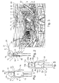
- Fig. 1
- a front view of a first embodiment of the manufacturing assistance device according to the present invention, as worn by a technician,
- Fig. 2
- a side view of the embodiment shown in
Fig. 1 , - Fig. 3
- a side view of the embodiment shown in
Fig. 1 , as used with a manufacturing tool during manufacture of an aircraft fuselage, - Fig. 4
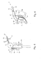
- a side view of a second embodiment of the manufacturing assistance device according to the invention, wherein the arm member is formed of multiple components made up of different materials,
- Fig. 5
- a front view of a third embodiment of the manufacturing assistance device according to the invention, comprising two arm members,
- Fig. 6
- a side view of a fourth embodiment of the manufacturing assistance device according to the invention, comprising an adjustment string,
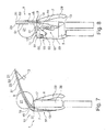
- Fig. 7
- a side view of a fifth embodiment of the manufacturing assistance device according to the invention, wherein the arm member is supported by a rope,
- Fig. 8
- a front view of the embodiment shown in
Fig. 7 , - Fig. 9
- a front view of a sixth embodiment of the manufacturing assistance device according to the invention, wherein the arm member comprises a plurality of arm sections controlled by a plurality of ropes,
- Fig. 10
- detailed views of the arm member of the embodiment shown in
Fig. 9 . - In
Figs. 1 and 2 a first embodiment of a wearablemanufacturing assistance device 1 for supporting a manufacturing tool 3 during manufacture of an aircraft or spacecraft is illustrated, as worn by atechnician 5. - The
manufacturing assistance device 1 comprises abody unit 7 and anarm member 9. Thebody unit 7 includes fastening means 11 for fastening thebody unit 7 to theback 13 of thetechnician 5 in a wearingposition 15, which is shown inFigs. 1 and 2 . In the present embodiment, thebody unit 7 is formed as a backpack, wherein the fastening means 11 are formed as belts configured to be passed around theshoulders 17 of atechnician 5. Theelongate arm member 9 has anattachment end 19 attached to thebody unit 7, and atool end 21 opposite to theattachment end 19. At the tool end 21 a mountingdevice 23 for mounting a manufacturing tool 3 to thearm member 9 is provided, as shown inFig. 3 . When thebody unit 7 is fastened to theback 13 of atechnician 5 in the wearingposition 15 and thearm member 9 is in aneutral position 25 where it is in an undeformed, relaxed state, thearm member 9 extends from theattachment end 19 at thebody unit 7 over theshoulder 17 and laterally past thehead 27 of thetechnician 5, so that thetool end 21 is in the view field of thetechnician 5 when looking straight ahead without turning or tilting thehead 27, and also within the radius of at least one of hisarms 29, so that he can hold the manufacturing tool 3 which is mounted to the mountingdevice 23 at thetool end 21 of the arm member 9 (seeFigs. 2 and 3 ) . As shown inFigs. 1 and 2 , thebody unit 7 has atop edge 31 which points to the top when thebody unit 7 is fastened to theback 13 of atechnician 5 in the wearingposition 15, and thearm member 9 extends beyond thistop edge 31, in the present case is attached to thebody unit 7 at thistop edge 31. - As illustrated in
Fig. 3 , with thearm member 9 extending over hisshoulder 17 and laterally past hishead 27 when thebody unit 7 is in the wearingposition 15 on hisback 13, thetechnician 5 is able to conveniently use themanufacturing assistance device 1 even in narrow spaces like the cargo compartment of anaircraft fuselage 33 where he has to work on his knees or in a bent-forward position, or when performing overhead work. The manufacturing tool 3 is steadily held in his view field in front of hishead 27 or slightly above hishead 27, by thearm member 9, and no parts of themanufacturing assistance device 1 proceed around or in front of historso 35 that could handicap him or cause damage on the aircraft to be manufactured. - The
arm member 9 of the embodiment shown inFigs. 1-3 is formed in one piece of a single material, namely a Polyform PE PF663 polyethylene foam material, so that it has a homogeneous stiffness along its length. Further, thearm member 9 has a circular or square-shaped cross section including a constant diameter along its length. In such a way thearm member 9 comprises a flexibility that allows it to bend such that thetool end 21 is moveable out of theneutral position 25, where thearm member 9 is undeformed or relaxed, within a radius of about 30 cm. Thearm member 9 has a length measured from thetop edge 31 of thebody unit 7 to thetool end 21 of about 75 cm, a diameter of about 3 cm, and a material with a Young's modulus of below 0.1 kN/mm2. The polyethylene foam material of thearm member 9 is softer than aluminum and common fiber composite materials, so that it cannot cause any damage on the aircraft or spacecraft to be manufactured. Further, thearm member 9 is removably attached to thebody unit 7, so that a modular configuration of themanufacturing assistance device 1 is obtained, wherein a plurality ofarm members 9 having different geometries and stiffness can be exchanged and mounted thebody unit 7, depending on the actual requirements of the situation. - In
Fig. 4 a second embodiment of themanufacturing assistance device 1 according to the invention is illustrated, wherein corresponding features are referred to by the same reference numerals as used in connection with the first embodiment. - The second embodiment differs from the first embodiment by the
arm member 9 being formed ofmultiple components 37, wherein eachcomponent 37 is formed of a different material. Additionally, thedifferent components 37 are detachably connected to one another, so that the stiffness of thearm member 9 can be adapted to different requirements by combiningspecific components 37 that together comprise the required stiffness. - In
Fig. 5 a third embodiment of themanufacturing assistance device 1 according to the invention is illustrated, wherein corresponding features are referred to by the same reference numerals as used in connection with the previous embodiments. - The third embodiment differs from the first embodiment in that it comprises two
distinct arm members arm member 9 is defined as afirst arm member 9a, itsattachment end 19 is defined as a first attachment end 19a, itstool end 21 is defined as afirst tool end 21a, and its mountingdevice 23 is defined as afirst mounting device 23a. Themanufacturing assistance device 1 comprises a secondelongate arm member 9b similar to thefirst arm member 9a, which has asecond attachment end 19b attached to thebody unit 7 and asecond tool end 21b opposite to theattachment end 19b, wherein at thesecond tool end 21b asecond mounting device 23b for mounting a manufacturing tool 3 to thesecond arm member 9b is provided. When thebody unit 7 is fastened to theback 13 of atechnician 5 in the wearingposition 15, as shown inFig. 5 , thesecond arm member 9b extends from thesecond attachment end 19b at thebody unit 7 over theshoulder 17 and laterally past thehead 27 of thetechnician 5, so that thesecond tool end 21b is in the view field of thetechnician 5 without turning or tilting hishead 27, similar to thefirst tool end 21a. Theshoulder 17 over which thesecond arm member 9b extends lies opposite to theshoulder 17 over which thefirst arm member 9a extends. By thesecond arm member 9b heavy manufacturing tools 3 can be additionally supported, or a second manufacturing tool 3 different from the first manufacturing tool 3 mounted to thefirst arm member 9a can be supported at the same time. - In
Fig. 6 a fourth embodiment of themanufacturing assistance device 1 according to the invention is illustrated, wherein corresponding features are referred to by the same reference numerals as used in connection with the previous embodiments. - The fourth embodiment differs from the first embodiment mainly by an
adjustment string 39 being provided which is connected to afirst string connector 41 at thebody unit 7 and to asecond string connector 43 at thearm member 9 in such a way that it forms a triangle together with thebody unit 7 and thearm member 9. Thelength 45 of theadjustment string 39 measured between thefirst string connector 41 and thesecond string connector 43 is adjustable, so that the angular position of thearm member 9 relative to thebody unit 7 is adjustable against the restoring force of theflexible arm member 9. In the present case, thelength 45 of theadjustment string 39 between the first andsecond string connectors ratchet mechanism 47 provided at thesecond string connector 43. - In
Fig. 7 and 8 a fifth embodiment of themanufacturing assistance device 1 according to the invention is illustrated, wherein corresponding features are referred to by the same reference numerals as used in connection with the previous embodiments. - The fifth embodiment differs from the first embodiment by the
arm member 9 being supported by arope 49 which is guided along theupper side 51 of thearm member 9. Afirst end 53 of therope 49 is connected to thearm member 9 near thetool end 21, and asecond end 55 of therope 49 is connected to a restoringelement 57 provided at thebody unit 7. As shown inFig. 8 , the restoringelement 57 in the present embodiment is formed as achain block mechanism 59 in combination with anelastic element 61 or acounter weight 63, so that the restoringelement 57 applies a restoring force to therope 49 which in turn causes a lifting force erecting thearm member 9 or at least supporting its stiffness. - In
Fig. 9 and 10 a sixth embodiment of themanufacturing assistance device 1 according to the invention is illustrated, wherein corresponding features are referred to by the same reference numerals as used in connection with the previous embodiments. - The sixth embodiment differs from the fifth embodiment by the
arm member 9 comprising a plurality ofarm sections 65 connected to one another by hinges 67. Further, a plurality ofropes 49 are guided along thearm member 9 from theattachment end 19 to thetool end 21, such that eachrope 49 is connected to eacharm section 65 via at least oneguiding device 69, which in the present embodiment is formed as a lug. InFig. 10a) thearm member 9 comprising threearm sections 65 together with the guidingdevices 69 guiding theropes 49 are shown. As shown inFigs. 10 b)-d) , theropes 49 are spaced from one another along the circumference of thearm member 9 by equal or repeating distances, when viewed in across section 71 of thearm member 9 perpendicular to its length direction. InFigs. 10 b)-d) threedifferent cross sections 71 are shown associated to therespective arm section 65, wherein inFig. 10 b) three equally spacedropes 49 are provided around the circumference of thecross section 71 of thearm section 65 with thetool end 21, inFig. 10 c) sixropes 49 are shown in equally spaced groups of two at thearm section 65 in the middle, and inFig. 10 d) nineropes 49 are shown provided around the circumference of thearm section 65 with theattachment end 19 in three equally spaced groups of three. - The three
arm sections 65 can be moved relative to one another by a defined movement of therespective ropes 49, which can be caused by anactuator 73. However, some of theropes 49 can also be connected to a passiveelastic element 61,chain block mechanism 59 or counter weight 63 (inFig. 9 only one rope is visible at thebody unit 7, which is controlled by anactuator 73, achain block mechanism 59, and an elastic element 61).
Claims (15)
- A wearable manufacturing assistance (1) device for supporting a manufacturing tool (3), the manufacturing assistance device (1) comprising
a body unit (7) including fastening means (11) for fastening the body unit (7) to the back (13) of a technician (5) in a wearing position (15), and
an arm member (9) which has an attachment end (19) attached to the body unit (7) and a tool end (21) opposite to the attachment end (19), wherein at the tool end (21) a mounting device (23) for mounting the manufacturing tool (3) to the arm member (9) is provided,
characterized in that
when the body unit (7) is fastened to the back (13) of the technician (5) in the wearing position (15), the arm member (9) extends from the attachment end (19) at the body unit (7) over a shoulder (17) and laterally past a head (27) of the technician (5). - The manufacturing assistance device according to claim 1, wherein the arm member (9) comprises a flexibility that allows it to bend in such a way that the tool end (21) is movable out of a neutral position (25) where the arm member (9) is undeformed, within a radius of between 10 and 50 cm, preferably between 20 and 40 cm, most preferred about 30 cm.
- The manufacturing assistance device according to claim 1 or 2, wherein the material of the arm member (9) is softer than aluminum, preferably softer than polymer resin typically used as matrix material of CFRP and GFRP structures, most preferred softer than polyether ether ketone (PEEK) material.
- The manufacturing assistance device according to any of claims 1 to 3, wherein the arm member (9) is formed in one piece.
- The manufacturing assistance device according to any of claims 1 to 4, wherein the arm member (9) has a homogeneous stiffness along its length.
- The manufacturing assistance device according to any of claims 1 to 5, wherein the arm member (9) is formed of a single material.
- The manufacturing assistance device according to any of claims 1 to 5, wherein the arm member (9) is formed of multiple components (37), wherein the components (37) are formed of different materials.
- The manufacturing assistance device according to claim 7, wherein the components (37) are detachably connected.
- The manufacturing assistance device according to any of claims 1 to 8, wherein the material of the arm member (9) is chosen from a foam, such as a polyethylene foam, from a CFRP, from a GFRP, or from a wood, such as bamboo.
- The manufacturing assistance device according to any of claims 1 to 9, wherein the arm member (9) is a first arm member (9a), its attachment end (19) is a first attachment end (19a), its tool end (21) is a first tool end (21a), and its mounting device (23) is a first mounting device (23a),
wherein the manufacturing assistance device (1) comprises a second arm member (9b) which has a second attachment end (19b) attached to the body unit (7) and a second tool end (21b) opposite to the second attachment end (19b), wherein at the second tool end (21b) a second mounting device (23b) for mounting a manufacturing tool (3) to the second arm member (9b) is provided,
wherein, when the body unit (7) is fastened to the back (13) of a technician (5) in the wearing position (15), the second arm member (9b) extends from the second attachment end (19b) at the body unit (7) over the shoulder (17) and laterally past the head (27) of the technician (5), and
wherein the shoulder (17) over which the second arm member (9b) extends lies opposite to the shoulder (17) over which the first arm member (9a) extends. - The manufacturing assistance device according to any of claims 2 and 3 to 10 when dependent from claim 2, wherein an adjustment string (39) is provided which is connected to a first string connector (41) at the body unit (7) and to a second string connector (43) at the arm member (9), and
wherein the length (45) of the adjustment string (39) measured between the first string connector (41) and the second string connector (43), is adjustable. - The manufacturing assistance device according to any of claims 1 to 11, wherein the body unit (7) is formed as a backpack, wherein the fastening means (11) are formed as belts configured to be passed around the shoulders (17) and/or the hip and/or the legs of a technician (5).
- The manufacturing assistance device according to any of claims 1 to 12, wherein the arm member (9) is removably attached to the body unit (7).
- The manufacturing assistance device according to any of claims 1 to 13, wherein the arm member (9) is supported by a rope (49) which is guided along the upper side (51) of the arm member (9),
wherein a first end (53) of the rope (49) is connected to the arm member (9) near the tool end (21), and a second end (55) of the rope (49) is connected to a restoring element (57) provided at the body unit (7). - The manufacturing assistance device according to claim 14, wherein the arm member (9) comprises a plurality of arm sections (65) connected to one another by hinges (67),
wherein a plurality of ropes (49) are guided along the arm member (9) from the attachment end (19) to the tool end (21), such that each rope (49) is connected to each arm section (65) via at least one guiding device (69), and
wherein, when viewed in a cross section (71) of the arm member (9), the ropes (49) are spaced from one another along the circumference of the arm member (9).
Priority Applications (4)
| Application Number | Priority Date | Filing Date | Title |
|---|---|---|---|
| EP15185353.8A EP3144107A1 (en) | 2015-09-15 | 2015-09-15 | A wearable manufacturing assistance device |
| CN201610821313.2A CN107031865A (en) | 2015-09-15 | 2016-09-13 | Wearable auxiliary manufacture device |
| JP2016179482A JP6505648B2 (en) | 2015-09-15 | 2016-09-14 | Wearable manufacturing assistance device |
| US15/266,737 US10710232B2 (en) | 2015-09-15 | 2016-09-15 | Wearable manufacturing assistance device |
Applications Claiming Priority (1)
| Application Number | Priority Date | Filing Date | Title |
|---|---|---|---|
| EP15185353.8A EP3144107A1 (en) | 2015-09-15 | 2015-09-15 | A wearable manufacturing assistance device |
Publications (1)
| Publication Number | Publication Date |
|---|---|
| EP3144107A1 true EP3144107A1 (en) | 2017-03-22 |
Family
ID=54147067
Family Applications (1)
| Application Number | Title | Priority Date | Filing Date |
|---|---|---|---|
| EP15185353.8A Withdrawn EP3144107A1 (en) | 2015-09-15 | 2015-09-15 | A wearable manufacturing assistance device |
Country Status (4)
| Country | Link |
|---|---|
| US (1) | US10710232B2 (en) |
| EP (1) | EP3144107A1 (en) |
| JP (1) | JP6505648B2 (en) |
| CN (1) | CN107031865A (en) |
Families Citing this family (2)
| Publication number | Priority date | Publication date | Assignee | Title |
|---|---|---|---|---|
| DE102015101329A1 (en) * | 2015-01-29 | 2016-08-04 | Airbus Operations Gmbh | Support device for stabilizing a body part of a person |
| FR3127427A1 (en) * | 2021-09-29 | 2023-03-31 | Supersonic Imagine | Wearable medical device |
Citations (4)
| Publication number | Priority date | Publication date | Assignee | Title |
|---|---|---|---|---|
| US3900140A (en) * | 1974-04-02 | 1975-08-19 | K & H Products Ltd | Rotatable carrying apparatus for video tape cameras and similar items |
| US4206983A (en) * | 1978-08-25 | 1980-06-10 | Continental Camera Systems, Inc. | Camera stabilizing body mount |
| WO1997014540A1 (en) * | 1995-10-19 | 1997-04-24 | Atlas Copco Berema Aktiebolag | A device for supporting hand-held machine-driven tools |
| US20100006611A1 (en) * | 2008-07-11 | 2010-01-14 | Michael Knowles | Support apparatus |
Family Cites Families (9)
| Publication number | Priority date | Publication date | Assignee | Title |
|---|---|---|---|---|
| US2676207A (en) * | 1953-05-22 | 1954-04-20 | Donovan D Hunt | Portable public address system |
| US3140800A (en) * | 1962-02-21 | 1964-07-14 | Charles F Henderson | Dispenser for granular materials |
| US4037763A (en) * | 1975-04-03 | 1977-07-26 | Video Components, Inc. | Instrument support |
| US4644654A (en) * | 1985-03-07 | 1987-02-24 | Howe Ernie W | Tree trimming apparatus |
| US6481108B1 (en) * | 2001-05-10 | 2002-11-19 | Edward Frank Helinski | Portable counterbalancing system for handheld implements |
| US20050023015A1 (en) * | 2003-07-29 | 2005-02-03 | Settimio Argento | Power-assisted multidirectional jackhammer positioner |
| US8505790B2 (en) * | 2010-06-07 | 2013-08-13 | David Chen Yu | Method and apparatus for attaching a personal electronic device |
| GB2501744B (en) * | 2012-05-03 | 2015-01-14 | Audiotel Internat Ltd | Weight distribution system for handheld sweep apparatus |
| EP3064822B1 (en) * | 2015-03-02 | 2018-05-30 | Easyrig AB | Camera rig |
-
2015
- 2015-09-15 EP EP15185353.8A patent/EP3144107A1/en not_active Withdrawn
-
2016
- 2016-09-13 CN CN201610821313.2A patent/CN107031865A/en active Pending
- 2016-09-14 JP JP2016179482A patent/JP6505648B2/en not_active Expired - Fee Related
- 2016-09-15 US US15/266,737 patent/US10710232B2/en active Active
Patent Citations (4)
| Publication number | Priority date | Publication date | Assignee | Title |
|---|---|---|---|---|
| US3900140A (en) * | 1974-04-02 | 1975-08-19 | K & H Products Ltd | Rotatable carrying apparatus for video tape cameras and similar items |
| US4206983A (en) * | 1978-08-25 | 1980-06-10 | Continental Camera Systems, Inc. | Camera stabilizing body mount |
| WO1997014540A1 (en) * | 1995-10-19 | 1997-04-24 | Atlas Copco Berema Aktiebolag | A device for supporting hand-held machine-driven tools |
| US20100006611A1 (en) * | 2008-07-11 | 2010-01-14 | Michael Knowles | Support apparatus |
Also Published As
| Publication number | Publication date |
|---|---|
| CN107031865A (en) | 2017-08-11 |
| US10710232B2 (en) | 2020-07-14 |
| US20170072555A1 (en) | 2017-03-16 |
| JP2017056551A (en) | 2017-03-23 |
| JP6505648B2 (en) | 2019-04-24 |
Similar Documents
| Publication | Publication Date | Title |
|---|---|---|
| KR102228294B1 (en) | Rehabilitation training apparatus | |
| US11311446B2 (en) | Exoskeleton for a human being | |
| EP3278938A1 (en) | Wearable apparatus for assisting a human when performing a load-involved task | |
| US11077009B2 (en) | Apparatus to apply forces in a three-dimensional space | |
| EP2992867A2 (en) | Carriage for a surgical boot of a hip distractor | |
| FR3046052B1 (en) | UPPER BODY MODULE FOR AN EXOSKELETON STRUCTURE | |
| WO2014195373A1 (en) | Lifting aid worn on the body | |
| US9999561B2 (en) | Shoulder and/or knee physical therapy and range of motion device | |
| US9403049B2 (en) | Exercise device | |
| US12226666B2 (en) | Wearable resistance training device | |
| US10710232B2 (en) | Wearable manufacturing assistance device | |
| KR102136125B1 (en) | With multiple hand angle cables | |
| US11524415B2 (en) | Boom arm for positioning an auxiliary electrical device | |
| CN101767339A (en) | manipulator | |
| DE102015208125A1 (en) | Support system for the human musculoskeletal system | |
| JP5465517B2 (en) | Operation bar for indirect hot line work | |
| US20140346316A1 (en) | Chest mounted worker's support | |
| JP2014239674A (en) | Arm supporting tool | |
| US20180295998A1 (en) | Dynamically adjustable arm lift (daal) accessory device | |
| EP1841392B1 (en) | Kinematic lying device | |
| US11197796B2 (en) | Mobile upper extremity (UE) supports for use in railed environments | |
| KR101997068B1 (en) | Shoulder Joint Tracking and Gravity-Compensating Device for Upper Limb Rehabilitation | |
| US20160081872A1 (en) | Spinal traction apparatus and method | |
| CN109259357B (en) | Labor protection device for paving operation | |
| ATE484184T1 (en) | PLACEMENT DEVICE AND EQUIPMENT DEVICE WITH A PLACEMENT DEVICE |
Legal Events
| Date | Code | Title | Description |
|---|---|---|---|
| PUAI | Public reference made under article 153(3) epc to a published international application that has entered the european phase |
Free format text: ORIGINAL CODE: 0009012 |
|
| AK | Designated contracting states |
Kind code of ref document: A1 Designated state(s): AL AT BE BG CH CY CZ DE DK EE ES FI FR GB GR HR HU IE IS IT LI LT LU LV MC MK MT NL NO PL PT RO RS SE SI SK SM TR |
|
| AX | Request for extension of the european patent |
Extension state: BA ME |
|
| 17P | Request for examination filed |
Effective date: 20170922 |
|
| RBV | Designated contracting states (corrected) |
Designated state(s): AL AT BE BG CH CY CZ DE DK EE ES FI FR GB GR HR HU IE IS IT LI LT LU LV MC MK MT NL NO PL PT RO RS SE SI SK SM TR |
|
| 17Q | First examination report despatched |
Effective date: 20181120 |
|
| GRAP | Despatch of communication of intention to grant a patent |
Free format text: ORIGINAL CODE: EPIDOSNIGR1 |
|
| INTG | Intention to grant announced |
Effective date: 20200316 |
|
| STAA | Information on the status of an ep patent application or granted ep patent |
Free format text: STATUS: THE APPLICATION IS DEEMED TO BE WITHDRAWN |
|
| 18D | Application deemed to be withdrawn |
Effective date: 20200728 |