EP3144056A2 - Low dispersion, fast response mixing device - Google Patents
Low dispersion, fast response mixing device Download PDFInfo
- Publication number
- EP3144056A2 EP3144056A2 EP16184781.9A EP16184781A EP3144056A2 EP 3144056 A2 EP3144056 A2 EP 3144056A2 EP 16184781 A EP16184781 A EP 16184781A EP 3144056 A2 EP3144056 A2 EP 3144056A2
- Authority
- EP
- European Patent Office
- Prior art keywords
- droplets
- mixing
- fluid
- emulsion
- working material
- Prior art date
- Legal status (The legal status is an assumption and is not a legal conclusion. Google has not performed a legal analysis and makes no representation as to the accuracy of the status listed.)
- Granted
Links
Images

Classifications
-
- B—PERFORMING OPERATIONS; TRANSPORTING
- B01—PHYSICAL OR CHEMICAL PROCESSES OR APPARATUS IN GENERAL
- B01F—MIXING, e.g. DISSOLVING, EMULSIFYING OR DISPERSING
- B01F23/00—Mixing according to the phases to be mixed, e.g. dispersing or emulsifying
- B01F23/40—Mixing liquids with liquids; Emulsifying
- B01F23/41—Emulsifying
-
- B—PERFORMING OPERATIONS; TRANSPORTING
- B01—PHYSICAL OR CHEMICAL PROCESSES OR APPARATUS IN GENERAL
- B01D—SEPARATION
- B01D61/00—Processes of separation using semi-permeable membranes, e.g. dialysis, osmosis or ultrafiltration; Apparatus, accessories or auxiliary operations specially adapted therefor
- B01D61/36—Pervaporation; Membrane distillation; Liquid permeation
- B01D61/363—Vapour permeation
-
- B—PERFORMING OPERATIONS; TRANSPORTING
- B01—PHYSICAL OR CHEMICAL PROCESSES OR APPARATUS IN GENERAL
- B01F—MIXING, e.g. DISSOLVING, EMULSIFYING OR DISPERSING
- B01F25/00—Flow mixers; Mixers for falling materials, e.g. solid particles
- B01F25/30—Injector mixers
- B01F25/31—Injector mixers in conduits or tubes through which the main component flows
- B01F25/314—Injector mixers in conduits or tubes through which the main component flows wherein additional components are introduced at the circumference of the conduit
- B01F25/3141—Injector mixers in conduits or tubes through which the main component flows wherein additional components are introduced at the circumference of the conduit with additional mixing means other than injector mixers
-
- B—PERFORMING OPERATIONS; TRANSPORTING
- B01—PHYSICAL OR CHEMICAL PROCESSES OR APPARATUS IN GENERAL
- B01F—MIXING, e.g. DISSOLVING, EMULSIFYING OR DISPERSING
- B01F25/00—Flow mixers; Mixers for falling materials, e.g. solid particles
- B01F25/30—Injector mixers
- B01F25/31—Injector mixers in conduits or tubes through which the main component flows
- B01F25/314—Injector mixers in conduits or tubes through which the main component flows wherein additional components are introduced at the circumference of the conduit
- B01F25/3142—Injector mixers in conduits or tubes through which the main component flows wherein additional components are introduced at the circumference of the conduit the conduit having a plurality of openings in the axial direction or in the circumferential direction
- B01F25/31422—Injector mixers in conduits or tubes through which the main component flows wherein additional components are introduced at the circumference of the conduit the conduit having a plurality of openings in the axial direction or in the circumferential direction with a plurality of perforations in the axial direction only
-
- B—PERFORMING OPERATIONS; TRANSPORTING
- B01—PHYSICAL OR CHEMICAL PROCESSES OR APPARATUS IN GENERAL
- B01F—MIXING, e.g. DISSOLVING, EMULSIFYING OR DISPERSING
- B01F33/00—Other mixers; Mixing plants; Combinations of mixers
- B01F33/30—Micromixers
-
- B—PERFORMING OPERATIONS; TRANSPORTING
- B01—PHYSICAL OR CHEMICAL PROCESSES OR APPARATUS IN GENERAL
- B01F—MIXING, e.g. DISSOLVING, EMULSIFYING OR DISPERSING
- B01F33/00—Other mixers; Mixing plants; Combinations of mixers
- B01F33/30—Micromixers
- B01F33/302—Micromixers the materials to be mixed flowing in the form of droplets
-
- B—PERFORMING OPERATIONS; TRANSPORTING
- B01—PHYSICAL OR CHEMICAL PROCESSES OR APPARATUS IN GENERAL
- B01F—MIXING, e.g. DISSOLVING, EMULSIFYING OR DISPERSING
- B01F35/00—Accessories for mixers; Auxiliary operations or auxiliary devices; Parts or details of general application
- B01F35/71—Feed mechanisms
- B01F35/717—Feed mechanisms characterised by the means for feeding the components to the mixer
- B01F35/7176—Feed mechanisms characterised by the means for feeding the components to the mixer using pumps
-
- B—PERFORMING OPERATIONS; TRANSPORTING
- B01—PHYSICAL OR CHEMICAL PROCESSES OR APPARATUS IN GENERAL
- B01F—MIXING, e.g. DISSOLVING, EMULSIFYING OR DISPERSING
- B01F35/00—Accessories for mixers; Auxiliary operations or auxiliary devices; Parts or details of general application
- B01F35/80—Forming a predetermined ratio of the substances to be mixed
- B01F35/81—Forming mixtures with changing ratios or gradients
-
- B—PERFORMING OPERATIONS; TRANSPORTING
- B29—WORKING OF PLASTICS; WORKING OF SUBSTANCES IN A PLASTIC STATE IN GENERAL
- B29C—SHAPING OR JOINING OF PLASTICS; SHAPING OF MATERIAL IN A PLASTIC STATE, NOT OTHERWISE PROVIDED FOR; AFTER-TREATMENT OF THE SHAPED PRODUCTS, e.g. REPAIRING
- B29C64/00—Additive manufacturing, i.e. manufacturing of three-dimensional [3D] objects by additive deposition, additive agglomeration or additive layering, e.g. by 3D printing, stereolithography or selective laser sintering
- B29C64/10—Processes of additive manufacturing
- B29C64/106—Processes of additive manufacturing using only liquids or viscous materials, e.g. depositing a continuous bead of viscous material
- B29C64/112—Processes of additive manufacturing using only liquids or viscous materials, e.g. depositing a continuous bead of viscous material using individual droplets, e.g. from jetting heads
Definitions
- This disclosure relates to rapid mixing of highly viscous materials, more particularly to rapid mixing of highly viscous materials in small volumes such as those used in digital printers.
- a digital functional gradient system is one that deposits materials having varying concentrations of different substances.
- the materials used usually have high viscosity.
- typical UV curable three-dimensional printing resins have viscosities roughly 10 to 1000 times higher than water.
- Thermoset resins also typically have viscosities much higher than that of water and the viscosity can be increased even higher with the addition of reinforcement agents such short fibers.
- the absolute size of a bead or drop of material is small.
- the combination of high viscosity and small geometry means that the Reynolds number is much less than 1.
- the Reynolds number is the ratio of inertial forces to viscous forces and consequently quantifies the relative importance of these two types of forces for given flow conditions.
- One goal behind mixing is to create the shortest possible diffusion path length, or in the case of immiscible polymer blending, to achieve nano-scale emulsion, by repeated cutting, folding and stretching operations. This is typically referred to as distributive mixing. At some very small diffusion path length, typically in the microns to nanometer scale, the material becomes sufficiently distributive such that diffusive mixing occurs.
- the ratio of the mix changes as the system deposits the material.
- the mixing In order to be able to control this gradient of mixture, the mixing must be achieved in a way that the components of a deposited material are mixed within a voxel (or volumetric pixel), but that nearby voxels are not mixed together substantially.
- the discussion here refers to mixing between voxels as upstream and downstream of flow, while mixing within voxels is characterized by cross flow mixing.
- In-line static mixers achieve multiple stretching and folding operations that reduce diffusion path length, but have high dispersion upstream and downstream.
- Twin-screw mixers typically achieve polymer compounding with multiple stretching and folding operations for extremely viscous fluids but have extremely high upstream and downstream dispersion.
- Microfluidic mixers use droplet fission, flow instabilities, or valves to achieve mixing, but these are typically demonstrated in aqueous media with significantly lower viscosities.
- Active mixers are highly complex concepts. These approaches use small chambers with stir bars, acoustics or electrical fields, but these do not work well with high viscosities and the small scales of interest in digital function material printing.
- One embodiment is a mixing system has a parallel droplet dispenser capable of making droplets of a first working material in the range of 10 nanometers to 10 micrometers, a pump to deliver fluid for the droplets of the first working material and to produce a first emulsion, a compact mixer having low inter-voxel mixing to receive the emulsion and produce a homogenous material, and a dispensing system.
- Another embodiment is a method of dispensing a graded material includes generating droplets of a first working material, the droplets having a size in the range of 10 nanometers to 10 micrometers, adding the droplets of the first working material into a fluid to create a first emulsion, wherein addition of the droplets of the first working material is controlled to create gradient in the emulsion, mixing the first emulsion to create a homogenous, graded mixture, and dispensing the homogenous, graded mixture onto a surface.
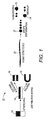
- Figure 1 shows a prior art process 10 for mixing.
- the majority of operations in static or twin mixers create surface area, referred to here as distributive mixing.
- the original material 12 most likely a high viscosity fluid undergoes stretching between 12 and 14.
- the mixer then cuts and stacks the material to create surface area as in 16 or folded as in 18, or more than likely a combination of both.
- Another method available for mixing is dispersive mixing.
- the process typically stretches the material at 20 and the material breaks into droplets at 22. Droplets break up as in 22 or coalesce as in 24, in single or multiple steps. Repetition and combinations of these steps generally leads to better dispersion. For example, one might start by taking a mixture of fluids through distributive mixing and then doing dispersive mixing. Multiple mixing steps that lead to good cross flow dispersion, often also lead to significant upstream and downstream dispersion.
- the dispersion of the mixed material can be defined as a measure of the degree of variation in composition across a volume.
- Various statistical measures can be made to quantify the degree of dispersion across a fluid domain. This can be measured across an entire fluid domain or a subset of that domain. For example, one can measure the dispersion of a mixed voxel, or between several voxels.
- low dispersion means a dispersion of a first fluid into a second fluid having a coefficient of dispersion less than 1.
- a “compact mixer” is one that has a size that has a working volume close to the size of a single voxel or less.
- a “voxel” is a volumetric pixel.
- the compact mixers under discussion here have 'low' inter-voxel mixing, defined as less than 10% cross-voxel mixing.
- voxels have a resolution depending upon their size. For a droplet based deposition system, such as a printer, the resolution generally correlates to the size of the deposited droplet.
- the size of a voxel relates to the cross section of the extrusion and the rate at which the composition of the extrudate can be changed.
- each material may be injected directly into the other fluid or a neutral carrier fluid that is not part of the final mixture.
- the diffusion rate In order to estimate the size of droplets needed, one must calculate the diffusion rate.
- the diffusivity of fluorescein dye in 70,000 MW 8g/dl dextran has been estimated to be approximately 4X10 -10 m 2 /s. If one assumes the mixing materials have diffusivities of 2 orders of magnitude slower, given a mixing time target of 0.01 s, a reasonable diffusion length estimate is 0.2 microns.
- the system may generate droplets upstream at a reduced rate that is easily accessible using other established means. Alternatively, it is possible to create larger drops that achieve the correct volume fraction and use downstream mixing to complete the creation of the required surface area.
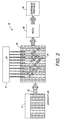
- the droplet mixer 30 has a first source of a carrier fluid 32.
- the source may be a tank, reservoir or other container 31.
- the carrier fluid may also consist of a second polymer material.
- the reservoir 34 allows the first polymer material 36 to be injected into the carrier fluid 32 in the form of small droplets.
- the injection of the droplets will typically be under the control of some sort of positive placement system such as a pump or other injector 37.
- the reservoir 34 represents the portion of the system creating the emulsion that would otherwise require a distributive mixing system, the replacement of which makes the system smaller and faster than using multiple mixing steps. By creating significant surface area directly, there is no need for distributive steps.
- the emulsion may undergo further downstream mixing at 38 and then is dispensed at printhead 39.
- Figures 3-5 show some embodiments of different configurations, with the understanding that these are merely examples and should not limit in anyway the scope of the claims.
- Figure 3 shows an embodiment in which the droplets of two different materials disperse into a same immiscible carrier liquid, one that cannot undergo mixing or blending.
- the first material 36 pre-disperses into the carrier fluid at reservoir 41 and the second material 32 is pre-dispersed into the carrier fluid at reservoir 43.
- Pumps 42 and 44 which may consist of gear pumps, then pump the material out of the reservoirs into a common channel 48.
- the ratio of the first and second material mixed is controlled by the relative flow rate of the pumps.
- a selective membrane 46 before the mixing and dispensing at 50 allows the carrier fluid to be removed.
- the carrier fluid can be recycled and reused.
- This system has the advantage of having easily controlled dispensing systems at a much larger scale than small droplet dispensing systems and a consistent, upstream process that may lack variation can create the small droplets. Examples include electrosprays or filament extensional atomizers. This allows droplet creation systems that may otherwise be difficult to engineer into the system
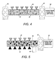
- a second fluid 32 and the first fluid 36 disperse into the common channel 48.
- the pump 42 enables the injection into the second fluid.
- the pump 44 pulls the liquid from the common channel and sends it to the downstream mixing and dispensing 50.
- the ratio of the first fluid and second fluid change by altering the rate of droplet dispensing of the first fluid in relation to the gear pump 42.
- the flow rate of the second optional gear pump 44 must equal the flow rate of the first pump 42 plus the flow rate of the droplet dispenser.
- one of the fluids may contain reinforcement agents, such as carbon fiber. In order to avoid making small droplets of reinforced material, the preferred embodiment is to dispense the material without reinforcement into the fluid with reinforcement.
- Figure 5 shows an embodiment in which the system dispenses the droplets of both materials into a carrier fluid, which later separates from the entire mixture before mixing and dispensing.
- the system dispenses the two polymers 32 and 36 into the common channel 48.
- the pump 42 provides positive displacement to inject the fluids and moves the mixed fluid downstream to the mixing and dispensing 50 through the separator, in this embodiment the separator consists of membrane 46.
- a positive displacement system applies some sort of positive force on the fluid injected into the other fluid.
- One possibility consists of a capillary and small piston. The piston actuates in the capillary to dispense a droplet of the fluid.
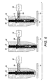
- Figure 6 shows an example of such a system.
- the dispenser 60 has a channel 64 in which a piston 62 moves.
- a single droplet system converts to a continuous droplet system with the addition of a one-way valve 66 that controls the flow of the fluid 68.
- the piston starts in the neutral position and then moves in a downward direction to touch the surface 70. This may increase the accuracy and decrease the droplet size.
- the surface 70 may be the bottom of the common channel 48 from the previous figures, or the reservoirs for the fluids.
- the piston moves upwards in the channel 62 as shown by the arrow.
- the system draws new fluid 68 through the one-way valve 66.
- the piston may have a seal 72 that prevents the fluid from moving in the wrong direction in the dispenser.
- a faster and smaller mixer can provide graded materials as part of a digital deposition system or printhead.
- the use of a droplet generator to create the emulsion eliminates the need for distributive mixing and allows the mixer to be smaller and mix fluids faster to reduce the overall volume in the system.
Landscapes
- Chemical & Material Sciences (AREA)
- Chemical Kinetics & Catalysis (AREA)
- Engineering & Computer Science (AREA)
- Water Supply & Treatment (AREA)
- Materials Engineering (AREA)
- Manufacturing & Machinery (AREA)
- Physics & Mathematics (AREA)
- Mechanical Engineering (AREA)
- Optics & Photonics (AREA)
- Accessories For Mixers (AREA)
- Processing And Handling Of Plastics And Other Materials For Molding In General (AREA)
Abstract
Description
- This disclosure relates to rapid mixing of highly viscous materials, more particularly to rapid mixing of highly viscous materials in small volumes such as those used in digital printers.
- Mixing is a common problem and there are many different approaches. However very few of them are appropriate for use in a high-resolution digital functional gradient manufacturing system. A digital functional gradient system is one that deposits materials having varying concentrations of different substances. The materials used usually have high viscosity. For example, typical UV curable three-dimensional printing resins have viscosities roughly 10 to 1000 times higher than water. Thermoset resins, also typically have viscosities much higher than that of water and the viscosity can be increased even higher with the addition of reinforcement agents such short fibers. In order to achieve high resolution, the absolute size of a bead or drop of material is small. The combination of high viscosity and small geometry means that the Reynolds number is much less than 1. The Reynolds number is the ratio of inertial forces to viscous forces and consequently quantifies the relative importance of these two types of forces for given flow conditions.
- One goal behind mixing is to create the shortest possible diffusion path length, or in the case of immiscible polymer blending, to achieve nano-scale emulsion, by repeated cutting, folding and stretching operations. This is typically referred to as distributive mixing. At some very small diffusion path length, typically in the microns to nanometer scale, the material becomes sufficiently distributive such that diffusive mixing occurs.
- In a digital functional gradient manufacturing system, the ratio of the mix changes as the system deposits the material. In order to be able to control this gradient of mixture, the mixing must be achieved in a way that the components of a deposited material are mixed within a voxel (or volumetric pixel), but that nearby voxels are not mixed together substantially. The discussion here refers to mixing between voxels as upstream and downstream of flow, while mixing within voxels is characterized by cross flow mixing.
- Current approaches include static line mixers, twin-screw mixers and microfluidic mixers, but none of them solves these particular problems. In-line static mixers achieve multiple stretching and folding operations that reduce diffusion path length, but have high dispersion upstream and downstream. Twin-screw mixers typically achieve polymer compounding with multiple stretching and folding operations for extremely viscous fluids but have extremely high upstream and downstream dispersion.
- Microfluidic mixers use droplet fission, flow instabilities, or valves to achieve mixing, but these are typically demonstrated in aqueous media with significantly lower viscosities. Active mixers are highly complex concepts. These approaches use small chambers with stir bars, acoustics or electrical fields, but these do not work well with high viscosities and the small scales of interest in digital function material printing.
- One embodiment is a mixing system has a parallel droplet dispenser capable of making droplets of a first working material in the range of 10 nanometers to 10 micrometers, a pump to deliver fluid for the droplets of the first working material and to produce a first emulsion, a compact mixer having low inter-voxel mixing to receive the emulsion and produce a homogenous material, and a dispensing system.
- Another embodiment is a method of dispensing a graded material includes generating droplets of a first working material, the droplets having a size in the range of 10 nanometers to 10 micrometers, adding the droplets of the first working material into a fluid to create a first emulsion, wherein addition of the droplets of the first working material is controlled to create gradient in the emulsion, mixing the first emulsion to create a homogenous, graded mixture, and dispensing the homogenous, graded mixture onto a surface.
-
-
Figure 1 shows a prior art embodiment of mixing. -
Figure 2 shows a system diagram of a mixer. -
Figures 3-5 show alternative embodiments of a mixing system. -
Figure 6 shows embodiments of a deposition nozzle. -
Figure 1 shows aprior art process 10 for mixing. The majority of operations in static or twin mixers create surface area, referred to here as distributive mixing. As shown inFigure 1 , theoriginal material 12, most likely a high viscosity fluid undergoes stretching between 12 and 14. The mixer then cuts and stacks the material to create surface area as in 16 or folded as in 18, or more than likely a combination of both. Another method available for mixing is dispersive mixing. The process typically stretches the material at 20 and the material breaks into droplets at 22. Droplets break up as in 22 or coalesce as in 24, in single or multiple steps. Repetition and combinations of these steps generally leads to better dispersion. For example, one might start by taking a mixture of fluids through distributive mixing and then doing dispersive mixing. Multiple mixing steps that lead to good cross flow dispersion, often also lead to significant upstream and downstream dispersion. - It is possible to skip multiple steps in the process by creating an emulsion of small droplets directly and varying the composition of the emulsion. This allows a relatively short mixing section with limited upstream and downstream dispersion to create a homogenous graded material with controlled and sharp changes in composition. The changes in composition provided digitally graded material for deposition on a substrate.
- The dispersion of the mixed material can be defined as a measure of the degree of variation in composition across a volume. Various statistical measures can be made to quantify the degree of dispersion across a fluid domain. This can be measured across an entire fluid domain or a subset of that domain. For example, one can measure the dispersion of a mixed voxel, or between several voxels.
- In the following discussion, "low dispersion" means a dispersion of a first fluid into a second fluid having a coefficient of dispersion less than 1. A "compact mixer" is one that has a size that has a working volume close to the size of a single voxel or less. A "voxel" is a volumetric pixel. The compact mixers under discussion here have 'low' inter-voxel mixing, defined as less than 10% cross-voxel mixing. Much like pixels, or picture elements, voxels have a resolution depending upon their size. For a droplet based deposition system, such as a printer, the resolution generally correlates to the size of the deposited droplet. For a continuous extrusion process such as a digital functional gradient manufacturing machine, the size of a voxel relates to the cross section of the extrusion and the rate at which the composition of the extrudate can be changed.
- One issue that arises in creating an emulsion lies in the dispensing of one material into another with sufficiently small droplet size to create an emulsion with little or no required additional mixing. However, it is possible. Several calculations support the viability of the embodiments here. For a voxel size of 100 microns, one assumes a hemisphere having a diameter of 100 microns to give a volume of roughly 250 Pico liters. For a deposition speed of 1 cm/s or 10,000 microns/sec, the rate of deposition for 100-micron voxels is 100 voxels/sec. In the most extreme case, when a voxel is mixed on demand and then immediately deposited, a mixer must be able to mix the voxel in less than 0.01s. However, it is possible to mix multiple voxels simultaneously. Mixing multiple voxels increase the complexity and size of the deposition system, but decreases the performance requirement on the mixer.
- To make a material with 50% volume fraction, it is necessary to inject 125 Pico liters/sec of each material. Each material may be injected directly into the other fluid or a neutral carrier fluid that is not part of the final mixture. In order to estimate the size of droplets needed, one must calculate the diffusion rate. As an example, the diffusivity of fluorescein dye in 70,000 MW 8g/dl dextran has been estimated to be approximately 4X10⁻¹⁰m2/s. If one assumes the mixing materials have diffusivities of 2 orders of magnitude slower, given a mixing time target of 0.01 s, a reasonable diffusion length estimate is 0.2 microns.
- Under these conditions, it would be ideal to produce droplets with a diameter of 0.2 microns or less. In order to achieve the deposition rates required for droplets produced on demand, 250,000 droplets must be produced every 0.01 seconds or 2.5 million droplets / s.
- It is worth noting that unlike a large number of small droplet dispensing techniques the distribution of droplet sizes is not of primary importance. These droplets are primarily used to create surface area between the fluids being mixed and will eventually be all mixed to together, so it is only important that the total dispensed volume is accurate. Even a system with a high coefficient of variation can achieve this by dispensing a large number of droplets.
- While 2.5 million droplets could be created per second using a high speed, such as a 100 kHz piezo actuator and thousands of nozzles, the mixing operations for a voxel do not necessarily need to be done within the deposition rate for one voxel. The system may generate droplets upstream at a reduced rate that is easily accessible using other established means. Alternatively, it is possible to create larger drops that achieve the correct volume fraction and use downstream mixing to complete the creation of the required surface area.
- A number of methods exist to produce small droplets of less than 1 micron. Using flow focusing architectures, such as extensional flows or elongational flows, it is possible to make drops using simple to fabricate geometries that can produce droplets on the order of a micron or less. References exist that show parallel nozzles for emulsion generation that can produce droplets on the order of 5 microns in a controllable, stable and robust manner. Spray techniques such as electrospray or filament extension atomization can produce large quantities of smaller particles, though another apparatus is required to modulate the quantity of droplets.
- The above discussion demonstrates that it is possible to achieve rapid and low axial dispersion mixing for the digital deposition of graded materials.
US Patent Application Serial No. 14/578,044, "SYSTEM FOR DIGITAL FABRICATION OF GRADED, HIERARCHICAL MATERIAL STRUCTURES," filed December 29, 2014 Figure 2. Figure 2 shows an embodiment of a droplet mixer for a digital functional graded material (DFGM) print head. - The
droplet mixer 30 has a first source of acarrier fluid 32. The source may be a tank, reservoir orother container 31. As will be discussed in more detail later with reference toFigures 3-5 , the carrier fluid may also consist of a second polymer material. Thereservoir 34 allows thefirst polymer material 36 to be injected into thecarrier fluid 32 in the form of small droplets. The injection of the droplets will typically be under the control of some sort of positive placement system such as a pump orother injector 37. - The
reservoir 34 represents the portion of the system creating the emulsion that would otherwise require a distributive mixing system, the replacement of which makes the system smaller and faster than using multiple mixing steps. By creating significant surface area directly, there is no need for distributive steps. After the creation of the emulsion, the emulsion may undergo further downstream mixing at 38 and then is dispensed atprinthead 39. - The embodiments of this system may take one of many forms.
Figures 3-5 show some embodiments of different configurations, with the understanding that these are merely examples and should not limit in anyway the scope of the claims.Figure 3 shows an embodiment in which the droplets of two different materials disperse into a same immiscible carrier liquid, one that cannot undergo mixing or blending. Thefirst material 36 pre-disperses into the carrier fluid atreservoir 41 and thesecond material 32 is pre-dispersed into the carrier fluid atreservoir 43.Pumps common channel 48. The ratio of the first and second material mixed is controlled by the relative flow rate of the pumps. Aselective membrane 46 before the mixing and dispensing at 50 allows the carrier fluid to be removed. The carrier fluid can be recycled and reused. - This system has the advantage of having easily controlled dispensing systems at a much larger scale than small droplet dispensing systems and a consistent, upstream process that may lack variation can create the small droplets. Examples include electrosprays or filament extensional atomizers. This allows droplet creation systems that may otherwise be difficult to engineer into the system
- In the
embodiment 40 ofFigure 4 , asecond fluid 32 and thefirst fluid 36 disperse into thecommon channel 48. Thepump 42 enables the injection into the second fluid. Thepump 44 pulls the liquid from the common channel and sends it to the downstream mixing and dispensing 50. The ratio of the first fluid and second fluid change by altering the rate of droplet dispensing of the first fluid in relation to thegear pump 42. The flow rate of the secondoptional gear pump 44 must equal the flow rate of thefirst pump 42 plus the flow rate of the droplet dispenser. In some embodiments, one of the fluids may contain reinforcement agents, such as carbon fiber. In order to avoid making small droplets of reinforced material, the preferred embodiment is to dispense the material without reinforcement into the fluid with reinforcement. -
Figure 5 shows an embodiment in which the system dispenses the droplets of both materials into a carrier fluid, which later separates from the entire mixture before mixing and dispensing. InFigure 5 , the system dispenses the twopolymers common channel 48. Thepump 42 provides positive displacement to inject the fluids and moves the mixed fluid downstream to the mixing and dispensing 50 through the separator, in this embodiment the separator consists ofmembrane 46. - One of the controlling factors in drop wise dispensing accuracy and precision is the pinch off behavior of the droplet. Both the surfaces of the dispensing apparatus and the fluid into which the droplet is being dispensed impacts this behavior. Controlling the fluid into which the droplet is dispensed reduces the systematic errors and non-linearity in the system due to change in the fluid into which the droplet is being dispensed.
- For higher viscosity fluids, such as those of interest here, one method of injection the droplets into another liquid uses a positive displacement system. A positive displacement system applies some sort of positive force on the fluid injected into the other fluid. One possibility consists of a capillary and small piston. The piston actuates in the capillary to dispense a droplet of the fluid.
Figure 6 shows an example of such a system. - The
dispenser 60 has achannel 64 in which apiston 62 moves. A single droplet system converts to a continuous droplet system with the addition of a one-way valve 66 that controls the flow of the fluid 68. The piston starts in the neutral position and then moves in a downward direction to touch thesurface 70. This may increase the accuracy and decrease the droplet size. When dispensing into another fluid, thesurface 70 may be the bottom of thecommon channel 48 from the previous figures, or the reservoirs for the fluids. After dispensing thedrop 74 on the surface, the piston moves upwards in thechannel 62 as shown by the arrow. The system drawsnew fluid 68 through the one-way valve 66. The piston may have aseal 72 that prevents the fluid from moving in the wrong direction in the dispenser. - In this manner, a faster and smaller mixer can provide graded materials as part of a digital deposition system or printhead. By controlling the flow of the two materials relative to each other, one can finely control the concentrations of the different polymers to have sharp changes in composition, creating the gradations desired. The use of a droplet generator to create the emulsion eliminates the need for distributive mixing and allows the mixer to be smaller and mix fluids faster to reduce the overall volume in the system.
- It will be appreciated that variants of the above-disclosed and other features and functions, or alternatives thereof, may be combined into many other different systems or applications. Various presently unforeseen or unanticipated alternatives, modifications, variations, or improvements therein may be subsequently made by those skilled in the art, which are also intended to be encompassed by the following claims.
Claims (10)
- A mixing system, comprising:a parallel droplet dispenser capable of making droplets of a first working material in the range of 10 nanometers to 10 micrometers;a pump to deliver fluid for the droplets of the first working material and to produce a first emulsion;a compact mixer with low inter-voxel mixing to receive the emulsion and produce a homogenous material; anda dispensing system.
- The mixing system of claim 1, wherein the pump delivers a carrier fluid into which the first working material is dispersed to produce the first emulsion.
- The mixing system of claim 2, further comprising a fluid separator to separate out the carrier fluid.
- The mixing system of claim 3, wherein the fluid separator comprises one of a membrane and an evaporator.
- The mixing system of claim 1, further comprising a second droplet dispenser capable of making droplets of a second working material in the range of 10 nanometers to 10 micrometers.
- A method of dispensing a graded material, comprising:generating droplets of a first working material, the droplets having a size in the range of 10 nanometers to 10 micrometers;adding the droplets of the first working material into a fluid to create a first emulsion, wherein addition of the droplets of the first working material is controlled to create gradient in the emulsion;mixing the first emulsion to create a homogenous, graded mixture; anddispensing the homogenous, graded mixture onto a surface.
- The method of claim 6, wherein the fluid comprises a carrier fluid.
- The method of claim 7, wherein the method further comprises separating the carrier fluid.
- The method of claim 6, wherein mixing comprises mixing the first and second emulsions.
- The method of claim 6, wherein adding the droplets of the first working material into a fluid comprises adding the droplets of the first working material into a fluid containing a second working material.
Applications Claiming Priority (1)
| Application Number | Priority Date | Filing Date | Title |
|---|---|---|---|
| US14/840,964 US10850236B2 (en) | 2015-08-31 | 2015-08-31 | Low dispersion, fast response mixing device |
Publications (3)
| Publication Number | Publication Date |
|---|---|
| EP3144056A2 true EP3144056A2 (en) | 2017-03-22 |
| EP3144056A3 EP3144056A3 (en) | 2017-07-26 |
| EP3144056B1 EP3144056B1 (en) | 2021-05-05 |
Family
ID=56738052
Family Applications (1)
| Application Number | Title | Priority Date | Filing Date |
|---|---|---|---|
| EP16184781.9A Active EP3144056B1 (en) | 2015-08-31 | 2016-08-18 | Low dispersion, fast response mixing and dispensing system and method |
Country Status (4)
| Country | Link |
|---|---|
| US (2) | US10850236B2 (en) |
| EP (1) | EP3144056B1 (en) |
| JP (1) | JP7125247B2 (en) |
| KR (1) | KR102399637B1 (en) |
Families Citing this family (2)
| Publication number | Priority date | Publication date | Assignee | Title |
|---|---|---|---|---|
| US10850236B2 (en) | 2015-08-31 | 2020-12-01 | Palo Alto Research Center Incorporated | Low dispersion, fast response mixing device |
| WO2023200954A1 (en) | 2022-04-13 | 2023-10-19 | Aprecia Pharmaceuticals LLC | System and method for additive manufacturing using an omnidirectional magnetic movement apparatus |
Family Cites Families (25)
| Publication number | Priority date | Publication date | Assignee | Title |
|---|---|---|---|---|
| US3712513A (en) * | 1970-05-12 | 1973-01-23 | Du Pont | Apparatus and method for gradient elution |
| US3635444A (en) | 1970-09-08 | 1972-01-18 | Amvit | Static mixer |
| US4946795A (en) | 1987-08-27 | 1990-08-07 | Biotrack, Inc. | Apparatus and method for dilution and mixing of liquid samples |
| US5480583A (en) * | 1991-12-02 | 1996-01-02 | Intevep, S.A. | Emulsion of viscous hydrocarbon in aqueous buffer solution and method for preparing same |
| JP2001088279A (en) * | 1999-09-20 | 2001-04-03 | Fuji Photo Film Co Ltd | Image forming method and apparatus |
| JP3996398B2 (en) * | 2002-01-08 | 2007-10-24 | 東北リコー株式会社 | Emulsion coating apparatus and method for producing thermal stencil printing master |
| US7485671B2 (en) | 2003-05-16 | 2009-02-03 | Velocys, Inc. | Process for forming an emulsion using microchannel process technology |
| JP4611989B2 (en) * | 2003-05-16 | 2011-01-12 | ヴェロシス,インク. | Process for making emulsions using microchannel process technology |
| US7344681B1 (en) | 2003-06-06 | 2008-03-18 | Sandia Corporation | Planar micromixer |
| JP4520166B2 (en) * | 2004-02-02 | 2010-08-04 | 独立行政法人農業・食品産業技術総合研究機構 | Resin microchannel substrate and manufacturing method thereof |
| DE102004008755A1 (en) | 2004-02-23 | 2005-09-08 | Hilti Ag | Static mixer and its use |
| JP3818384B2 (en) | 2004-03-30 | 2006-09-06 | 独立行政法人食品総合研究所 | Emulsion production apparatus, reaction apparatus, microcapsule production method using the reaction apparatus, microtube production method, and microtube |
| US20050238721A1 (en) | 2004-04-07 | 2005-10-27 | Acquarulo Lawrence A Jr | One step compounding extrusion of drug filled polymers |
| DE602004015424D1 (en) | 2004-05-24 | 2008-09-11 | Borealis Tech Oy | Use of a counter-rotating twin screw extruder for the fusion of multimodal polymer compositions |
| KR100571845B1 (en) | 2004-10-28 | 2006-04-17 | 삼성전자주식회사 | Fluid mixing method and mixing device using the method |
| CN101132853B (en) * | 2004-11-17 | 2012-05-09 | 万罗赛斯公司 | Emulsification method using microchannel processing technology |
| ATE534893T1 (en) | 2005-10-06 | 2011-12-15 | Rhodia Operations | MICROFLUID EVAPORATOR AND METHOD FOR DETERMINING PHYSICAL AND/OR CHEMICAL PROPERTIES OF CHEMICAL COMPOUNDS OR MIXTURES OF CHEMICAL COMPOUNDS |
| JP4946180B2 (en) * | 2006-05-29 | 2012-06-06 | 株式会社日立プラントテクノロジー | Emulsifying device |
| DE102007020244B4 (en) | 2007-04-24 | 2009-03-19 | INSTITUT FüR MIKROTECHNIK MAINZ GMBH | Acoustic stirring and stirring device with such and method for stirring and mixing |
| GB0712860D0 (en) | 2007-07-03 | 2007-08-08 | Eastman Kodak Co | continuous inkjet drop generation device |
| CN102056838B (en) | 2008-04-11 | 2013-07-03 | 弗卢丁公司 | Microfluidic devices and methods |
| WO2010111231A1 (en) | 2009-03-23 | 2010-09-30 | Raindance Technologies, Inc. | Manipulation of microfluidic droplets |
| US8936353B2 (en) | 2012-03-28 | 2015-01-20 | Eastman Kodak Company | Digital drop patterning device and method |
| CN105765055A (en) * | 2013-08-27 | 2016-07-13 | 基纽拜奥股份有限公司 | Microfluidic devices and methods of their use |
| US10850236B2 (en) | 2015-08-31 | 2020-12-01 | Palo Alto Research Center Incorporated | Low dispersion, fast response mixing device |
-
2015
- 2015-08-31 US US14/840,964 patent/US10850236B2/en active Active
-
2016
- 2016-08-10 JP JP2016157826A patent/JP7125247B2/en active Active
- 2016-08-11 KR KR1020160102319A patent/KR102399637B1/en not_active Expired - Fee Related
- 2016-08-18 EP EP16184781.9A patent/EP3144056B1/en active Active
-
2020
- 2020-10-26 US US17/080,574 patent/US11904277B2/en active Active
Also Published As
| Publication number | Publication date |
|---|---|
| EP3144056A3 (en) | 2017-07-26 |
| KR102399637B1 (en) | 2022-05-19 |
| US10850236B2 (en) | 2020-12-01 |
| US20210039046A1 (en) | 2021-02-11 |
| JP2017047414A (en) | 2017-03-09 |
| KR20170026134A (en) | 2017-03-08 |
| US20170056843A1 (en) | 2017-03-02 |
| JP7125247B2 (en) | 2022-08-24 |
| EP3144056B1 (en) | 2021-05-05 |
| US11904277B2 (en) | 2024-02-20 |
Similar Documents
| Publication | Publication Date | Title |
|---|---|---|
| JP5602016B2 (en) | Method and microfluidic device for producing composite droplets | |
| Sun et al. | Comparison of micro-dispensing performance between micro-valve and piezoelectric printhead | |
| US11904277B2 (en) | Low dispersion, fast response mixing device | |
| Shen et al. | A robust ink deposition system for binder jetting and material jetting | |
| Waasdorp et al. | Accessing individual 75-micron diameter nozzles of a desktop inkjet printer to dispense picoliter droplets on demand | |
| WO1998036832A1 (en) | Microdosing device and method for operating same | |
| JP2016055284A (en) | Apparatus and methods for dispensing small beads of viscous material | |
| EP1049538A1 (en) | Microdosing device | |
| CN101765502B (en) | Continuous Jet Drop Generator | |
| US20130277461A1 (en) | Method And Electro-Fluidic Device To Produce Emulsions And Particle Suspensions | |
| US8272716B2 (en) | Method of continuous inkjet printing | |
| Poozesh et al. | Comprehensive examination of a new mechanism to produce small droplets in drop-on-demand inkjet technology | |
| US20220062999A1 (en) | Powdered build material distribution | |
| JP2016032805A (en) | Micro fluid discharge method and micro fluid dispenser | |
| US8633955B2 (en) | Digital drop patterning and deposition device | |
| Goyal et al. | Evolution and Motion of Non-Newtonian Liquid Drops Ejected from a Nozzle in a Newtonian Medium Inside a Microchannel | |
| 진용현 | Stabilization plan of inkjet process through evaluation of rheological properties | |
| Lindemann et al. | PipeJet™-A Simple Disposable Dispenser for the Nanoliter Range | |
| US8932677B2 (en) | Digital drop patterning and deposition device | |
| US20160067733A1 (en) | Apparatuses and methods for dispensing predetermined quantities of liquid onto a substrate | |
| Labarre | Microfluidic T-junction | |
| WO2022071947A1 (en) | Digital microfluidic mixed fluid droplets | |
| Kasböck | Evaluation of Additive Manufacturing Processes with Liquids and Pastes: Evaluation of Additive Manufacturing Processes with Liquids and Pastes | |
| JP2005087953A (en) | Paint supplying apparatus and its valve unit | |
| Shaqfeh | Wednesday Morning, November 11, 2009 |
Legal Events
| Date | Code | Title | Description |
|---|---|---|---|
| PUAI | Public reference made under article 153(3) epc to a published international application that has entered the european phase |
Free format text: ORIGINAL CODE: 0009012 |
|
| STAA | Information on the status of an ep patent application or granted ep patent |
Free format text: STATUS: THE APPLICATION HAS BEEN PUBLISHED |
|
| AK | Designated contracting states |
Kind code of ref document: A2 Designated state(s): AL AT BE BG CH CY CZ DE DK EE ES FI FR GB GR HR HU IE IS IT LI LT LU LV MC MK MT NL NO PL PT RO RS SE SI SK SM TR |
|
| AX | Request for extension of the european patent |
Extension state: BA ME |
|
| PUAL | Search report despatched |
Free format text: ORIGINAL CODE: 0009013 |
|
| AK | Designated contracting states |
Kind code of ref document: A3 Designated state(s): AL AT BE BG CH CY CZ DE DK EE ES FI FR GB GR HR HU IE IS IT LI LT LU LV MC MK MT NL NO PL PT RO RS SE SI SK SM TR |
|
| AX | Request for extension of the european patent |
Extension state: BA ME |
|
| RIC1 | Information provided on ipc code assigned before grant |
Ipc: B29C 67/00 20170101ALI20170616BHEP Ipc: B41J 2/005 20060101ALI20170616BHEP Ipc: B01F 15/04 20060101ALI20170616BHEP Ipc: B01F 13/00 20060101ALI20170616BHEP Ipc: B01F 5/04 20060101ALI20170616BHEP Ipc: B01F 15/02 20060101ALI20170616BHEP Ipc: B01F 3/08 20060101AFI20170616BHEP |
|
| STAA | Information on the status of an ep patent application or granted ep patent |
Free format text: STATUS: REQUEST FOR EXAMINATION WAS MADE |
|
| 17P | Request for examination filed |
Effective date: 20180126 |
|
| RBV | Designated contracting states (corrected) |
Designated state(s): AL AT BE BG CH CY CZ DE DK EE ES FI FR GB GR HR HU IE IS IT LI LT LU LV MC MK MT NL NO PL PT RO RS SE SI SK SM TR |
|
| STAA | Information on the status of an ep patent application or granted ep patent |
Free format text: STATUS: EXAMINATION IS IN PROGRESS |
|
| 17Q | First examination report despatched |
Effective date: 20200327 |
|
| GRAP | Despatch of communication of intention to grant a patent |
Free format text: ORIGINAL CODE: EPIDOSNIGR1 |
|
| STAA | Information on the status of an ep patent application or granted ep patent |
Free format text: STATUS: GRANT OF PATENT IS INTENDED |
|
| RIC1 | Information provided on ipc code assigned before grant |
Ipc: B01F 15/02 20060101ALI20201113BHEP Ipc: B01F 5/04 20060101ALI20201113BHEP Ipc: B01F 13/00 20060101ALI20201113BHEP Ipc: B01F 3/08 20060101AFI20201113BHEP Ipc: B29C 64/112 20170101ALI20201113BHEP Ipc: B01F 15/04 20060101ALI20201113BHEP Ipc: B33Y 70/00 20200101ALI20201113BHEP |
|
| INTG | Intention to grant announced |
Effective date: 20201201 |
|
| GRAS | Grant fee paid |
Free format text: ORIGINAL CODE: EPIDOSNIGR3 |
|
| GRAA | (expected) grant |
Free format text: ORIGINAL CODE: 0009210 |
|
| STAA | Information on the status of an ep patent application or granted ep patent |
Free format text: STATUS: THE PATENT HAS BEEN GRANTED |
|
| AK | Designated contracting states |
Kind code of ref document: B1 Designated state(s): AL AT BE BG CH CY CZ DE DK EE ES FI FR GB GR HR HU IE IS IT LI LT LU LV MC MK MT NL NO PL PT RO RS SE SI SK SM TR |
|
| REG | Reference to a national code |
Ref country code: GB Ref legal event code: FG4D |
|
| REG | Reference to a national code |
Ref country code: CH Ref legal event code: EP |
|
| REG | Reference to a national code |
Ref country code: AT Ref legal event code: REF Ref document number: 1389101 Country of ref document: AT Kind code of ref document: T Effective date: 20210515 |
|
| REG | Reference to a national code |
Ref country code: IE Ref legal event code: FG4D |
|
| REG | Reference to a national code |
Ref country code: DE Ref legal event code: R096 Ref document number: 602016057259 Country of ref document: DE |
|
| REG | Reference to a national code |
Ref country code: LT Ref legal event code: MG9D |
|
| REG | Reference to a national code |
Ref country code: AT Ref legal event code: MK05 Ref document number: 1389101 Country of ref document: AT Kind code of ref document: T Effective date: 20210505 |
|
| PG25 | Lapsed in a contracting state [announced via postgrant information from national office to epo] |
Ref country code: FI Free format text: LAPSE BECAUSE OF FAILURE TO SUBMIT A TRANSLATION OF THE DESCRIPTION OR TO PAY THE FEE WITHIN THE PRESCRIBED TIME-LIMIT Effective date: 20210505 Ref country code: LT Free format text: LAPSE BECAUSE OF FAILURE TO SUBMIT A TRANSLATION OF THE DESCRIPTION OR TO PAY THE FEE WITHIN THE PRESCRIBED TIME-LIMIT Effective date: 20210505 Ref country code: BG Free format text: LAPSE BECAUSE OF FAILURE TO SUBMIT A TRANSLATION OF THE DESCRIPTION OR TO PAY THE FEE WITHIN THE PRESCRIBED TIME-LIMIT Effective date: 20210805 Ref country code: AT Free format text: LAPSE BECAUSE OF FAILURE TO SUBMIT A TRANSLATION OF THE DESCRIPTION OR TO PAY THE FEE WITHIN THE PRESCRIBED TIME-LIMIT Effective date: 20210505 Ref country code: HR Free format text: LAPSE BECAUSE OF FAILURE TO SUBMIT A TRANSLATION OF THE DESCRIPTION OR TO PAY THE FEE WITHIN THE PRESCRIBED TIME-LIMIT Effective date: 20210505 |
|
| REG | Reference to a national code |
Ref country code: DE Ref legal event code: R079 Ref document number: 602016057259 Country of ref document: DE Free format text: PREVIOUS MAIN CLASS: B01F0003080000 Ipc: B01F0023400000 |
|
| PG25 | Lapsed in a contracting state [announced via postgrant information from national office to epo] |
Ref country code: ES Free format text: LAPSE BECAUSE OF FAILURE TO SUBMIT A TRANSLATION OF THE DESCRIPTION OR TO PAY THE FEE WITHIN THE PRESCRIBED TIME-LIMIT Effective date: 20210505 Ref country code: NO Free format text: LAPSE BECAUSE OF FAILURE TO SUBMIT A TRANSLATION OF THE DESCRIPTION OR TO PAY THE FEE WITHIN THE PRESCRIBED TIME-LIMIT Effective date: 20210805 Ref country code: PL Free format text: LAPSE BECAUSE OF FAILURE TO SUBMIT A TRANSLATION OF THE DESCRIPTION OR TO PAY THE FEE WITHIN THE PRESCRIBED TIME-LIMIT Effective date: 20210505 Ref country code: PT Free format text: LAPSE BECAUSE OF FAILURE TO SUBMIT A TRANSLATION OF THE DESCRIPTION OR TO PAY THE FEE WITHIN THE PRESCRIBED TIME-LIMIT Effective date: 20210906 Ref country code: RS Free format text: LAPSE BECAUSE OF FAILURE TO SUBMIT A TRANSLATION OF THE DESCRIPTION OR TO PAY THE FEE WITHIN THE PRESCRIBED TIME-LIMIT Effective date: 20210505 Ref country code: SE Free format text: LAPSE BECAUSE OF FAILURE TO SUBMIT A TRANSLATION OF THE DESCRIPTION OR TO PAY THE FEE WITHIN THE PRESCRIBED TIME-LIMIT Effective date: 20210505 Ref country code: GR Free format text: LAPSE BECAUSE OF FAILURE TO SUBMIT A TRANSLATION OF THE DESCRIPTION OR TO PAY THE FEE WITHIN THE PRESCRIBED TIME-LIMIT Effective date: 20210806 Ref country code: LV Free format text: LAPSE BECAUSE OF FAILURE TO SUBMIT A TRANSLATION OF THE DESCRIPTION OR TO PAY THE FEE WITHIN THE PRESCRIBED TIME-LIMIT Effective date: 20210505 Ref country code: IS Free format text: LAPSE BECAUSE OF FAILURE TO SUBMIT A TRANSLATION OF THE DESCRIPTION OR TO PAY THE FEE WITHIN THE PRESCRIBED TIME-LIMIT Effective date: 20210905 |
|
| REG | Reference to a national code |
Ref country code: NL Ref legal event code: MP Effective date: 20210505 |
|
| PG25 | Lapsed in a contracting state [announced via postgrant information from national office to epo] |
Ref country code: NL Free format text: LAPSE BECAUSE OF FAILURE TO SUBMIT A TRANSLATION OF THE DESCRIPTION OR TO PAY THE FEE WITHIN THE PRESCRIBED TIME-LIMIT Effective date: 20210505 |
|
| PG25 | Lapsed in a contracting state [announced via postgrant information from national office to epo] |
Ref country code: RO Free format text: LAPSE BECAUSE OF FAILURE TO SUBMIT A TRANSLATION OF THE DESCRIPTION OR TO PAY THE FEE WITHIN THE PRESCRIBED TIME-LIMIT Effective date: 20210505 Ref country code: CZ Free format text: LAPSE BECAUSE OF FAILURE TO SUBMIT A TRANSLATION OF THE DESCRIPTION OR TO PAY THE FEE WITHIN THE PRESCRIBED TIME-LIMIT Effective date: 20210505 Ref country code: DK Free format text: LAPSE BECAUSE OF FAILURE TO SUBMIT A TRANSLATION OF THE DESCRIPTION OR TO PAY THE FEE WITHIN THE PRESCRIBED TIME-LIMIT Effective date: 20210505 Ref country code: EE Free format text: LAPSE BECAUSE OF FAILURE TO SUBMIT A TRANSLATION OF THE DESCRIPTION OR TO PAY THE FEE WITHIN THE PRESCRIBED TIME-LIMIT Effective date: 20210505 Ref country code: SK Free format text: LAPSE BECAUSE OF FAILURE TO SUBMIT A TRANSLATION OF THE DESCRIPTION OR TO PAY THE FEE WITHIN THE PRESCRIBED TIME-LIMIT Effective date: 20210505 Ref country code: SM Free format text: LAPSE BECAUSE OF FAILURE TO SUBMIT A TRANSLATION OF THE DESCRIPTION OR TO PAY THE FEE WITHIN THE PRESCRIBED TIME-LIMIT Effective date: 20210505 |
|
| REG | Reference to a national code |
Ref country code: DE Ref legal event code: R097 Ref document number: 602016057259 Country of ref document: DE |
|
| PLBE | No opposition filed within time limit |
Free format text: ORIGINAL CODE: 0009261 |
|
| STAA | Information on the status of an ep patent application or granted ep patent |
Free format text: STATUS: NO OPPOSITION FILED WITHIN TIME LIMIT |
|
| REG | Reference to a national code |
Ref country code: CH Ref legal event code: PL |
|
| PG25 | Lapsed in a contracting state [announced via postgrant information from national office to epo] |
Ref country code: MC Free format text: LAPSE BECAUSE OF FAILURE TO SUBMIT A TRANSLATION OF THE DESCRIPTION OR TO PAY THE FEE WITHIN THE PRESCRIBED TIME-LIMIT Effective date: 20210505 |
|
| 26N | No opposition filed |
Effective date: 20220208 |
|
| REG | Reference to a national code |
Ref country code: BE Ref legal event code: MM Effective date: 20210831 |
|
| PG25 | Lapsed in a contracting state [announced via postgrant information from national office to epo] |
Ref country code: LI Free format text: LAPSE BECAUSE OF NON-PAYMENT OF DUE FEES Effective date: 20210831 Ref country code: CH Free format text: LAPSE BECAUSE OF NON-PAYMENT OF DUE FEES Effective date: 20210831 |
|
| PG25 | Lapsed in a contracting state [announced via postgrant information from national office to epo] |
Ref country code: IS Free format text: LAPSE BECAUSE OF FAILURE TO SUBMIT A TRANSLATION OF THE DESCRIPTION OR TO PAY THE FEE WITHIN THE PRESCRIBED TIME-LIMIT Effective date: 20210905 Ref country code: LU Free format text: LAPSE BECAUSE OF NON-PAYMENT OF DUE FEES Effective date: 20210818 Ref country code: AL Free format text: LAPSE BECAUSE OF FAILURE TO SUBMIT A TRANSLATION OF THE DESCRIPTION OR TO PAY THE FEE WITHIN THE PRESCRIBED TIME-LIMIT Effective date: 20210505 |
|
| PG25 | Lapsed in a contracting state [announced via postgrant information from national office to epo] |
Ref country code: IT Free format text: LAPSE BECAUSE OF FAILURE TO SUBMIT A TRANSLATION OF THE DESCRIPTION OR TO PAY THE FEE WITHIN THE PRESCRIBED TIME-LIMIT Effective date: 20210505 Ref country code: IE Free format text: LAPSE BECAUSE OF NON-PAYMENT OF DUE FEES Effective date: 20210818 Ref country code: BE Free format text: LAPSE BECAUSE OF NON-PAYMENT OF DUE FEES Effective date: 20210831 |
|
| PG25 | Lapsed in a contracting state [announced via postgrant information from national office to epo] |
Ref country code: HU Free format text: LAPSE BECAUSE OF FAILURE TO SUBMIT A TRANSLATION OF THE DESCRIPTION OR TO PAY THE FEE WITHIN THE PRESCRIBED TIME-LIMIT; INVALID AB INITIO Effective date: 20160818 |
|
| PG25 | Lapsed in a contracting state [announced via postgrant information from national office to epo] |
Ref country code: CY Free format text: LAPSE BECAUSE OF FAILURE TO SUBMIT A TRANSLATION OF THE DESCRIPTION OR TO PAY THE FEE WITHIN THE PRESCRIBED TIME-LIMIT Effective date: 20210505 |
|
| PG25 | Lapsed in a contracting state [announced via postgrant information from national office to epo] |
Ref country code: MK Free format text: LAPSE BECAUSE OF FAILURE TO SUBMIT A TRANSLATION OF THE DESCRIPTION OR TO PAY THE FEE WITHIN THE PRESCRIBED TIME-LIMIT Effective date: 20210505 |
|
| PG25 | Lapsed in a contracting state [announced via postgrant information from national office to epo] |
Ref country code: TR Free format text: LAPSE BECAUSE OF FAILURE TO SUBMIT A TRANSLATION OF THE DESCRIPTION OR TO PAY THE FEE WITHIN THE PRESCRIBED TIME-LIMIT Effective date: 20210505 |
|
| PG25 | Lapsed in a contracting state [announced via postgrant information from national office to epo] |
Ref country code: MT Free format text: LAPSE BECAUSE OF FAILURE TO SUBMIT A TRANSLATION OF THE DESCRIPTION OR TO PAY THE FEE WITHIN THE PRESCRIBED TIME-LIMIT Effective date: 20210505 |
|
| PGFP | Annual fee paid to national office [announced via postgrant information from national office to epo] |
Ref country code: DE Payment date: 20251128 Year of fee payment: 10 |
|
| PGFP | Annual fee paid to national office [announced via postgrant information from national office to epo] |
Ref country code: GB Payment date: 20251128 Year of fee payment: 10 |
|
| PGFP | Annual fee paid to national office [announced via postgrant information from national office to epo] |
Ref country code: FR Payment date: 20251128 Year of fee payment: 10 |