EP3144021A1 - Blood purification device - Google Patents
Blood purification device Download PDFInfo
- Publication number
- EP3144021A1 EP3144021A1 EP15792192.5A EP15792192A EP3144021A1 EP 3144021 A1 EP3144021 A1 EP 3144021A1 EP 15792192 A EP15792192 A EP 15792192A EP 3144021 A1 EP3144021 A1 EP 3144021A1
- Authority
- EP
- European Patent Office
- Prior art keywords
- blood purification
- hanger portion
- container bag
- use position
- purification treatment
- Prior art date
- Legal status (The legal status is an assumption and is not a legal conclusion. Google has not performed a legal analysis and makes no representation as to the accuracy of the status listed.)
- Granted
Links
Images






Classifications
-
- A—HUMAN NECESSITIES
- A61—MEDICAL OR VETERINARY SCIENCE; HYGIENE
- A61M—DEVICES FOR INTRODUCING MEDIA INTO, OR ONTO, THE BODY; DEVICES FOR TRANSDUCING BODY MEDIA OR FOR TAKING MEDIA FROM THE BODY; DEVICES FOR PRODUCING OR ENDING SLEEP OR STUPOR
- A61M1/00—Suction or pumping devices for medical purposes; Devices for carrying-off, for treatment of, or for carrying-over, body-liquids; Drainage systems
- A61M1/14—Dialysis systems; Artificial kidneys; Blood oxygenators ; Reciprocating systems for treatment of body fluids, e.g. single needle systems for hemofiltration or pheresis
- A61M1/16—Dialysis systems; Artificial kidneys; Blood oxygenators ; Reciprocating systems for treatment of body fluids, e.g. single needle systems for hemofiltration or pheresis with membranes
- A61M1/1621—Constructional aspects thereof
- A61M1/1643—Constructional aspects thereof with weighing of fresh and used dialysis fluid
-
- A—HUMAN NECESSITIES
- A61—MEDICAL OR VETERINARY SCIENCE; HYGIENE
- A61M—DEVICES FOR INTRODUCING MEDIA INTO, OR ONTO, THE BODY; DEVICES FOR TRANSDUCING BODY MEDIA OR FOR TAKING MEDIA FROM THE BODY; DEVICES FOR PRODUCING OR ENDING SLEEP OR STUPOR
- A61M1/00—Suction or pumping devices for medical purposes; Devices for carrying-off, for treatment of, or for carrying-over, body-liquids; Drainage systems
- A61M1/14—Dialysis systems; Artificial kidneys; Blood oxygenators ; Reciprocating systems for treatment of body fluids, e.g. single needle systems for hemofiltration or pheresis
-
- A—HUMAN NECESSITIES
- A61—MEDICAL OR VETERINARY SCIENCE; HYGIENE
- A61M—DEVICES FOR INTRODUCING MEDIA INTO, OR ONTO, THE BODY; DEVICES FOR TRANSDUCING BODY MEDIA OR FOR TAKING MEDIA FROM THE BODY; DEVICES FOR PRODUCING OR ENDING SLEEP OR STUPOR
- A61M1/00—Suction or pumping devices for medical purposes; Devices for carrying-off, for treatment of, or for carrying-over, body-liquids; Drainage systems
- A61M1/14—Dialysis systems; Artificial kidneys; Blood oxygenators ; Reciprocating systems for treatment of body fluids, e.g. single needle systems for hemofiltration or pheresis
- A61M1/16—Dialysis systems; Artificial kidneys; Blood oxygenators ; Reciprocating systems for treatment of body fluids, e.g. single needle systems for hemofiltration or pheresis with membranes
- A61M1/1621—Constructional aspects thereof
-
- A—HUMAN NECESSITIES
- A61—MEDICAL OR VETERINARY SCIENCE; HYGIENE
- A61M—DEVICES FOR INTRODUCING MEDIA INTO, OR ONTO, THE BODY; DEVICES FOR TRANSDUCING BODY MEDIA OR FOR TAKING MEDIA FROM THE BODY; DEVICES FOR PRODUCING OR ENDING SLEEP OR STUPOR
- A61M1/00—Suction or pumping devices for medical purposes; Devices for carrying-off, for treatment of, or for carrying-over, body-liquids; Drainage systems
- A61M1/34—Filtering material out of the blood by passing it through a membrane, i.e. hemofiltration or diafiltration
-
- A—HUMAN NECESSITIES
- A61—MEDICAL OR VETERINARY SCIENCE; HYGIENE
- A61M—DEVICES FOR INTRODUCING MEDIA INTO, OR ONTO, THE BODY; DEVICES FOR TRANSDUCING BODY MEDIA OR FOR TAKING MEDIA FROM THE BODY; DEVICES FOR PRODUCING OR ENDING SLEEP OR STUPOR
- A61M1/00—Suction or pumping devices for medical purposes; Devices for carrying-off, for treatment of, or for carrying-over, body-liquids; Drainage systems
- A61M1/36—Other treatment of blood in a by-pass of the natural circulatory system, e.g. temperature adaptation, irradiation ; Extra-corporeal blood circuits
- A61M1/3621—Extra-corporeal blood circuits
- A61M1/367—Circuit parts not covered by the preceding subgroups of group A61M1/3621
-
- A—HUMAN NECESSITIES
- A61—MEDICAL OR VETERINARY SCIENCE; HYGIENE
- A61M—DEVICES FOR INTRODUCING MEDIA INTO, OR ONTO, THE BODY; DEVICES FOR TRANSDUCING BODY MEDIA OR FOR TAKING MEDIA FROM THE BODY; DEVICES FOR PRODUCING OR ENDING SLEEP OR STUPOR
- A61M5/00—Devices for bringing media into the body in a subcutaneous, intra-vascular or intramuscular way; Accessories therefor, e.g. filling or cleaning devices, arm-rests
- A61M5/14—Infusion devices, e.g. infusing by gravity; Blood infusion; Accessories therefor
- A61M5/1414—Hanging-up devices
- A61M5/1417—Holders or handles for hanging up infusion containers
-
- A—HUMAN NECESSITIES
- A61—MEDICAL OR VETERINARY SCIENCE; HYGIENE
- A61M—DEVICES FOR INTRODUCING MEDIA INTO, OR ONTO, THE BODY; DEVICES FOR TRANSDUCING BODY MEDIA OR FOR TAKING MEDIA FROM THE BODY; DEVICES FOR PRODUCING OR ENDING SLEEP OR STUPOR
- A61M5/00—Devices for bringing media into the body in a subcutaneous, intra-vascular or intramuscular way; Accessories therefor, e.g. filling or cleaning devices, arm-rests
- A61M5/14—Infusion devices, e.g. infusing by gravity; Blood infusion; Accessories therefor
- A61M5/168—Means for controlling media flow to the body or for metering media to the body, e.g. drip meters, counters ; Monitoring media flow to the body
- A61M5/16831—Monitoring, detecting, signalling or eliminating infusion flow anomalies
- A61M5/1684—Monitoring, detecting, signalling or eliminating infusion flow anomalies by detecting the amount of infusate remaining, e.g. signalling end of infusion
- A61M5/16845—Monitoring, detecting, signalling or eliminating infusion flow anomalies by detecting the amount of infusate remaining, e.g. signalling end of infusion by weight
-
- F—MECHANICAL ENGINEERING; LIGHTING; HEATING; WEAPONS; BLASTING
- F16—ENGINEERING ELEMENTS AND UNITS; GENERAL MEASURES FOR PRODUCING AND MAINTAINING EFFECTIVE FUNCTIONING OF MACHINES OR INSTALLATIONS; THERMAL INSULATION IN GENERAL
- F16B—DEVICES FOR FASTENING OR SECURING CONSTRUCTIONAL ELEMENTS OR MACHINE PARTS TOGETHER, e.g. NAILS, BOLTS, CIRCLIPS, CLAMPS, CLIPS OR WEDGES; JOINTS OR JOINTING
- F16B45/00—Hooks; Eyes
- F16B45/02—Hooks with pivoting or elastically bending closing member
-
- A—HUMAN NECESSITIES
- A61—MEDICAL OR VETERINARY SCIENCE; HYGIENE
- A61M—DEVICES FOR INTRODUCING MEDIA INTO, OR ONTO, THE BODY; DEVICES FOR TRANSDUCING BODY MEDIA OR FOR TAKING MEDIA FROM THE BODY; DEVICES FOR PRODUCING OR ENDING SLEEP OR STUPOR
- A61M1/00—Suction or pumping devices for medical purposes; Devices for carrying-off, for treatment of, or for carrying-over, body-liquids; Drainage systems
- A61M1/14—Dialysis systems; Artificial kidneys; Blood oxygenators ; Reciprocating systems for treatment of body fluids, e.g. single needle systems for hemofiltration or pheresis
- A61M1/16—Dialysis systems; Artificial kidneys; Blood oxygenators ; Reciprocating systems for treatment of body fluids, e.g. single needle systems for hemofiltration or pheresis with membranes
- A61M1/1601—Control or regulation
-
- A—HUMAN NECESSITIES
- A61—MEDICAL OR VETERINARY SCIENCE; HYGIENE
- A61M—DEVICES FOR INTRODUCING MEDIA INTO, OR ONTO, THE BODY; DEVICES FOR TRANSDUCING BODY MEDIA OR FOR TAKING MEDIA FROM THE BODY; DEVICES FOR PRODUCING OR ENDING SLEEP OR STUPOR
- A61M2205/00—General characteristics of the apparatus
- A61M2205/18—General characteristics of the apparatus with alarm
-
- A—HUMAN NECESSITIES
- A61—MEDICAL OR VETERINARY SCIENCE; HYGIENE
- A61M—DEVICES FOR INTRODUCING MEDIA INTO, OR ONTO, THE BODY; DEVICES FOR TRANSDUCING BODY MEDIA OR FOR TAKING MEDIA FROM THE BODY; DEVICES FOR PRODUCING OR ENDING SLEEP OR STUPOR
- A61M2205/00—General characteristics of the apparatus
- A61M2205/27—General characteristics of the apparatus preventing use
- A61M2205/276—General characteristics of the apparatus preventing use preventing unwanted use
-
- A—HUMAN NECESSITIES
- A61—MEDICAL OR VETERINARY SCIENCE; HYGIENE
- A61M—DEVICES FOR INTRODUCING MEDIA INTO, OR ONTO, THE BODY; DEVICES FOR TRANSDUCING BODY MEDIA OR FOR TAKING MEDIA FROM THE BODY; DEVICES FOR PRODUCING OR ENDING SLEEP OR STUPOR
- A61M2205/00—General characteristics of the apparatus
- A61M2205/33—Controlling, regulating or measuring
- A61M2205/3379—Masses, volumes, levels of fluids in reservoirs, flow rates
- A61M2205/3393—Masses, volumes, levels of fluids in reservoirs, flow rates by weighing the reservoir
-
- A—HUMAN NECESSITIES
- A61—MEDICAL OR VETERINARY SCIENCE; HYGIENE
- A61M—DEVICES FOR INTRODUCING MEDIA INTO, OR ONTO, THE BODY; DEVICES FOR TRANSDUCING BODY MEDIA OR FOR TAKING MEDIA FROM THE BODY; DEVICES FOR PRODUCING OR ENDING SLEEP OR STUPOR
- A61M2209/00—Ancillary equipment
- A61M2209/08—Supports for equipment
- A61M2209/082—Mounting brackets, arm supports for equipment
-
- A—HUMAN NECESSITIES
- A61—MEDICAL OR VETERINARY SCIENCE; HYGIENE
- A61M—DEVICES FOR INTRODUCING MEDIA INTO, OR ONTO, THE BODY; DEVICES FOR TRANSDUCING BODY MEDIA OR FOR TAKING MEDIA FROM THE BODY; DEVICES FOR PRODUCING OR ENDING SLEEP OR STUPOR
- A61M2209/00—Ancillary equipment
- A61M2209/08—Supports for equipment
- A61M2209/084—Supporting bases, stands for equipment
-
- A—HUMAN NECESSITIES
- A61—MEDICAL OR VETERINARY SCIENCE; HYGIENE
- A61M—DEVICES FOR INTRODUCING MEDIA INTO, OR ONTO, THE BODY; DEVICES FOR TRANSDUCING BODY MEDIA OR FOR TAKING MEDIA FROM THE BODY; DEVICES FOR PRODUCING OR ENDING SLEEP OR STUPOR
- A61M5/00—Devices for bringing media into the body in a subcutaneous, intra-vascular or intramuscular way; Accessories therefor, e.g. filling or cleaning devices, arm-rests
- A61M5/14—Infusion devices, e.g. infusing by gravity; Blood infusion; Accessories therefor
Definitions
- the present invention relates to a blood purification apparatus that includes a holding device capable of holding a container bag containing a liquid for blood purification treatment, such as dialysate, substitution fluid, or anticoagulant, and that is capable of performing blood purification treatment using the liquid in the container bag.
- a liquid for blood purification treatment such as dialysate, substitution fluid, or anticoagulant
- a conventional blood purification apparatus that performs blood purification treatment using container bags in which dialysate, substitution fluid, and the like are contained (a dialysate bag and a substitution fluid bag) includes a hanger portion having hook portions to which the container bags can be attached, and a measuring device (load meter) capable of measuring the weights of the container bags held by the hanger portion.
- dialysate is supplied from a container bag in which dialysate is contained (container bag for dialysate) to a blood purifier (dialyzer) at a predetermined flow rate, and drainage from the blood purifier is caused to be contained in another container bag (container bag for drainage) at a predetermined flow rate.
- substitution fluid can also be supplied from a container bag in which substitution fluid is contained (container bag for substitution fluid) to a blood circuit at a predetermined flow rate.
- the blood purification apparatus cannot distinguish between a weight decrease due to damage to the container bag and a weight decrease due to the fact that a worker detached the container bag from the hanger portion.
- the present invention has been made in consideration of such circumstances, and an object of the present invention is to provide a blood purification apparatus in which inadvertent replacement of a container bag attached to a hanger portion can be avoided.
- a blood purification apparatus including a holding device capable of holding a container bag that contains a liquid for blood purification treatment, such as dialysate, substitution fluid, or anticoagulant, the blood purification apparatus being capable of performing blood purification treatment using the liquid in the container bag, wherein the holding device includes a hanger portion including an attachment portion to which the container bag can be attached, and movable between a use position in which the container bag is used and a replacement position in which the container bag is replaced, a measuring device capable of measuring the weight of the container bag held by the hanger portion, and a restricting device that restricts attachment and detachment of the container bag to and from the attachment portion when the hanger portion is in the use position.
- a holding device capable of holding a container bag that contains a liquid for blood purification treatment, such as dialysate, substitution fluid, or anticoagulant
- the blood purification apparatus being capable of performing blood purification treatment using the liquid in the container bag
- the holding device includes a hanger portion including an attachment portion to which the container bag
- the blood purification apparatus according to Claim 1, wherein the restricting device is a shielding plate that is fixed to an apparatus main body and that covers and shields the attachment portion only when the hanger portion is in the use position.
- the restricting device is a shielding plate that is fixed to an apparatus main body and that covers and shields the attachment portion only when the hanger portion is in the use position.
- the blood purification apparatus according to Claim 1, wherein the restricting device is a shielding plate that is attached to the hanger portion and that is movable between a first position in which the attachment portion is shielded and a second position in which the attachment portion is open, the restricting device being movable from the first position to the second position only when the hanger portion is in the replacement position.
- the restricting device is a shielding plate that is attached to the hanger portion and that is movable between a first position in which the attachment portion is shielded and a second position in which the attachment portion is open, the restricting device being movable from the first position to the second position only when the hanger portion is in the replacement position.
- the blood purification apparatus according to any one of Claims 1 to 3, further comprising a detecting device detecting that the hanger portion is in the use position, and wherein when, during the blood purification treatment, the detecting device does not detect that the hanger portion is in the use position, it is informed that the hanger portion is not in the use position.
- the blood purification apparatus according to any one of Claims 1 to 3, further comprising a detecting device detecting that the hanger portion is in the use position, and wherein when, during the blood purification treatment, the detecting device does not detect that the hanger portion is in the use position, control relating to the blood purification treatment is stopped.
- the blood purification apparatus according to Claim 5, wherein when, after the control relating to the blood purification treatment is stopped, the detecting device detects that the hanger portion is in the use position, the control relating to the blood purification treatment is resumed.
- the holding device includes a restricting device that restricts attachment and detachment of the container bags to and from the attachment portion when the hanger portion is in the use position. Therefore, inadvertent replacement of the container bags attached to the hanger portion can be avoided.
- the restricting device is a shielding plate that is fixed to an apparatus main body and that covers and shields the attachment portion only when the hanger portion is in the use position. Therefore, inadvertent replacement of the container bag when the hanger portion is in the use position can be reliably avoided, and the configuration of the hanger portion can be simplified.
- the restricting device is a shielding plate that is attached to the hanger portion and that is movable between a first position in which the attachment portion is shielded and a second position in which the attachment portion is open, the restricting device being movable from the first position to the second position only when the hanger portion is in the replacement position. Therefore, inadvertent replacement of the container bag when the hanger portion is in the use position can be reliably avoided, and the restricting device can be caused to follow the hanger portion.
- the blood purification apparatus further includes a detecting device detecting that the hanger portion is in the use position, and when, during the blood purification treatment, the detecting device does not detect that the hanger portion is in the use position, it is informed that the hanger portion is not in the use position. Therefore, the worker can reliably grasp that the hanger portion is not in a position in which the container bag can be replaced.
- the blood purification apparatus further includes a detecting device detecting that the hanger portion is in the use position, and when, during the blood purification treatment, the detecting device does not detect that the hanger portion is in the use position, control relating to the blood purification treatment is stopped. Therefore, inadvertent replacement of the container bag during the blood purification treatment can be reliably avoided.
- the detecting device detects that the hanger portion is in the use position
- the control relating to the blood purification treatment is resumed. Therefore, the control relating to the blood purification treatment is performed only when the hanger portion is in the use position (that is, when the replacement of the container bag is restricted by the restricting device), and inadvertent replacement of the container bag during the blood purification treatment can be reliably avoided, and the resumption after the stop of the control relating to the blood purification treatment can be performed automatically.
- a blood purification apparatus 1 is for providing a patient with blood purification treatment (treatment such as hemodialysis (HD), hemodiafiltration (HDF), hemofiltration (HF), or continuous hemodiafiltration (CHF)), and, as shown in Figs. 1 to 13 , includes an apparatus main body A in which a holding device 2 holding container bags B1 to B3, a display 3, a clamping device 4, a holding device 5 holding a container bag B4, a control device H, and peristaltic pumps (P1 to P4) are formed.
- a holding device 2 holding container bags B1 to B3, a display 3, a clamping device 4, a holding device 5 holding a container bag B4, a control device H, and peristaltic pumps (P1 to P4) are formed.
- the container bags B1 to B4 are bag-like containers made of nylon or the like for containing liquid for the blood purification treatment.
- the container bag B1 contains dialysate to be supplied to a dialyzer 9 (see Fig. 13 )
- the container bag B2 contains drainage from the dialyzer 9
- the container bag B3 contains substitution fluid
- the container bag B4 contains a drug administered during the blood purification treatment, such as anticoagulant.
- the display 3 is, for example, a touch panel having a liquid crystal screen or the like, and is configured to be capable of displaying the setting relating to the blood purification treatment, the state of a patient, and the like.
- the clamping device 4 is capable of clamping the dialyzer 9, and is configured such that the blood of the patient can be purified by the dialyzer 9.
- the dialyzer 9 is formed by housing a plurality of hollow fibers with pores in a case, in which a blood inlet port 9a, a blood outlet port 9b, a dialysate inlet port 9c, and a dialysate outlet port 9d are formed.
- an arterial blood circuit 8a is connected to the blood inlet port 9a, and the proximal end of a venous blood circuit 8b is connected to the blood outlet port 9b.
- a blood pump which is a peristaltic pump P1 is disposed in the middle of the arterial blood circuit 8a.
- An arterial puncture needle a and a venous puncture needle b that can be inserted into the patient can be attached to the distal ends of the arterial blood circuit 8a and the venous blood circuit 8b, respectively.
- the peristaltic pump P1 When, after the arterial puncture needle a and the venous puncture needle b are inserted into the patient, the peristaltic pump P1 is driven, the blood of the patient can be circulated extracorporeally through the arterial blood circuit 8a and the venous blood circuit 8b, and blood purification by the dialyzer 9 is performed in the process of the extracorporeal circulation.
- the dialysate inlet port 9c is connected through the peristaltic pump P3 to the container bag B1.
- the dialysate outlet port 9d is connected through the peristaltic pump P2 to the container bag B2.
- the container bag B3 is connected through a substitution pump, which is a peristaltic pump P4, to the venous blood circuit 8b.
- the substitution fluid in the container bag B3 can be supplied to the venous blood circuit 8b.
- the holding device 2 is for holding the above-described container bags, and includes a main body portion 2a, a hanger portion 2b that has attachment portions 2c to which the container bags (B1 to B3) can be attached, and that is movable between a use position in which the container bags (B1 to B3) are used (see Figs. 1 to 6 ) and a replacement position in which the container bags (B1 to B3) are replaced (see Figs. 7 to 12 ), and measuring devices g capable of measuring the weights of the container bags (B1 to B3) held by the hanger portion 2b (see Fig. 13 ).
- the main body portion 2a movably supports the hanger portion 2b, and includes, in this embodiment, a shaft portion L for swinging the hanger portion 2b, and a detecting device S, which is a sensor capable of detecting that the shaft portion L is in a predetermined position. That is, when the hanger portion 2b is under the main body portion 2a as shown in Figs. 5 and 6 , the hanger portion 2b is in the "use position.” When the hanger portion 2b is swung about the shaft portion L, and the hanger portion 2b is in a position distant from the main body portion 2a as shown in Figs. 11 and 12 , the hanger portion 2b is in the "replacement position.”
- the shaft portion L is a rotating shaft that rotates with the swing of the hanger portion 2b, and a protrusion La is formed on part thereof.
- the protrusion La is detected by the detecting device S, and an electric signal is transmitted to the control device H. That is, it can be detected that the hanger portion 2b is in the use position, from the fact that the detecting device S is in an ON state (it can also be detected that the hanger portion 2b is not in the use position, from the fact that the detecting device S is in an OFF state).
- the hanger portion 2b is a bar-like member one end of which is attached to the shaft portion L, and has attachment portions 2c formed at predetermined intervals.
- the attachment portions 2c are hooks from which the container bags (B1 to B3) can be hung and that can hold them, and the measuring devices g are disposed at the respective proximal ends thereof.
- the measuring devices g are load meters that measure applied loads, and measure the weights of the container bags (B1 to B3) hung from the attachment portions 2c (the total weights of the container bags and the contents), and can transmit the measured values as electric signals to the control device H.
- dialysate can be supplied to the dialyzer 9 at a predetermined flow rate, and drainage can be discharged from the dialyzer 9 at a predetermined flow rate.
- substitution fluid can be supplied to the venous blood circuit 8b at a predetermined flow rate.
- the holding device 2 has a restricting device 6 that restricts the attachment and detachment of the container bags (B1 to B3) to and from the attachment portions 2c when the hanger portion 2b is in the use position.
- the restricting device 6 is a shielding plate that is fixed to the apparatus main body A and that covers and shields the attachment portions 2c only when the hanger portion 2b is in the use position, and is formed, for example, by pressing a metal plate material into a substantially U shape, so as to have a front portion 6a, a lower surface portion 6b, and a flange portion 6c.
- the front portion 6a, the lower surface portion 6b, and the flange portion 6c of the restricting device 6 cover and shield the attachment portions 2c formed in the hanger portion 2b and restrict the attachment and detachment of the container bags (B1 to B3) to and from the attachment portions 2c (physically restrict the attachment and detachment).
- the hanger portion 2b is swung from the use position to the replacement position, as shown in Figs. 11 and 12 , the hanger portion 2b is distant from the restricting device 6 and the attachment portions 2c are not shielded, and the attachment and detachment of the container bags (B1 to B3) to and from the attachment portions 2c are allowed.
- the detecting device S when, during the blood purification treatment, the detecting device S does not detect that the hanger portion 2b is in the use position (that is, when the hanger portion 2b is not in the use position), it is informed that the hanger portion 2b is not in the use position.
- Such information may be displayed by the display 3, or may be output by a speaker, a warning light, or the like (not shown). The worker can thereby reliably grasp that the hanger portion 2b is not in a position in which the container bags (B1 to B3) can be replaced (replacement position).
- the control device H is configured to stop the control relating to the blood purification treatment when, during the blood purification treatment, the detecting device S does not detect that the hanger portion 2b is in the use position, and to resume the control relating to the blood purification treatment when, after the control relating to the blood purification treatment is stopped, the detecting device S detects that the hanger portion 2b is in the use position.
- the control relating to the blood purification treatment is stopped when, during the blood purification treatment, the detecting device S does not detect that the hanger portion 2b is in the use position, inadvertent replacement of the container bags (B1 to B3) during the blood purification treatment can be reliably avoided.
- the control relating to the blood purification treatment is resumed when, after the control relating to the blood purification treatment is stopped, the detecting device S detects that the hanger portion 2b is in the use position, the control relating to the blood purification treatment is performed only when the hanger portion 2b is in the use position (that is, when the replacement of the container bags (B1 to B3) is restricted by the restricting device 6), and inadvertent replacement of the container bags (B1 to B3) during the blood purification treatment can be reliably avoided, and the resumption after the stop of the control relating to the blood purification treatment can be performed automatically.
- the container bag B4 containing a drug administered during the blood purification treatment, such as anticoagulant is held by the holding device 5.
- the holding device 5 has a hanger portion 5b in which an attachment portion 5c, which is a hook, is formed.
- a restricting device 7 that restricts the attachment and detachment of the container bag B4 to and from the attachment portion 5c when the hanger portion is in the use position as shown in Fig. 2 is attached to the apparatus main body A.
- the hanger portion 2b is set in the replacement position, the container bags (B1 to B3) are attached to the attachment portions 2c of the holding device 2, the container bag B4 is attached to the attachment portion 5c of the holding device 5, and then the hanger portion 2b (the same goes for the hanger portion 5b of the holding device 5) is moved to the use position and the blood purification treatment is performed (S1).
- the processing proceeds to S3, and the control relating to the blood purification treatment (for example, the driving of the peristaltic pumps P1 to P4 and the measurement by the measuring devices g) is stopped.
- the control relating to the blood purification treatment remains stopped. If the hanger portion 2b is moved to the use position, the processing proceeds to S5, and the control relating to the blood purification treatment (for example, the driving of the peristaltic pumps P1 to P4 and the measurement by the measuring devices g) is resumed.
- the above embodiment has the restricting device 6 that restricts the attachment and detachment of the container bags (B1 to B3) to and from the attachment portions 2c when the hanger portion 2b is in the use position, inadvertent replacement of the container bags (B1 to B3) attached to the hanger portion 2b can be avoided.
- Inadvertent replacement of the container bags (B1 to B3) is physically restricted when the hanger portion 2b is in the use position. Therefore, if the measured values of the measuring devices g are abnormal when the hanger portion 2b is in the use position, it is mainly caused by a problem with the blood purification apparatus 1, such as damage to the container bags (B1 to B3). Therefore, a false alarm can be prevented.
- the restricting device 6 (the same goes for the restricting device 7) according to this embodiment is a shielding plate that is fixed to the apparatus main body A and that covers and shields the attachment portions 2c only when the hanger portion 2b is in the use position. Therefore, inadvertent replacement of the container bags (B1 to B3) when the hanger portion 2b is in the use position can be reliably avoided, and the configuration of the hanger portion 2b can be simplified.
- the blood purification apparatus is, as with the first embodiment, for providing a patient with blood purification treatment, and, as shown in Figs. 15 to 18 , includes a holding device 10 including a main body portion 10a, a hanger portion 10b that has attachment portions 10c to which container bags (B1 to B3) can be attached, and that is movable between a use position in which the container bags (B1 to B3) are used (see Figs. 15 and 16 ) and a replacement position in which the container bags (B1 to B3) are replaced (see Figs. 17 and 18 ), and measuring devices g capable of measuring the weights of the container bags (B1 to B3) held by the hanger portion 10b (see Fig. 13 ).
- the description of the same configuration as that of the first embodiment (particularly the configuration of the apparatus main body A) will be omitted.
- the main body portion 10a movably supports the hanger portion 10b, and includes, as with the first embodiment, a shaft portion L for swinging the hanger portion 10b, and a detecting device S, which is a sensor capable of detecting that the shaft portion L is in a predetermined position. That is, when the hanger portion 10b is under the main body portion 10a as shown in Figs. 15 and 16 , the hanger portion 10b is in the "use position.” When the hanger portion 10b is swung about the shaft portion L, and the hanger portion 10b is in a position distant from the main body portion 10a as shown in Figs. 17 and 18 , the hanger portion 10b is in the "replacement position.”
- the hanger portion 10b is a bar-like member one end of which is attached to the shaft portion L, and has attachment portions 10c formed at predetermined intervals.
- the attachment portions 10c are hooks from which the container bags (B1 to B3) can be hung and that can hold them, and the measuring devices g are disposed at the respective proximal ends thereof.
- the measuring devices g are load meters that measure applied loads, and measure the weights of the container bags (B1 to B3) hung from the attachment portions 10c (the total weights of the container bags and the contents), and can transmit the measured values as electric signals to the control device H.
- the holding device 10 has a restricting device 11 that restricts the attachment and detachment of the container bags (B1 to B3) to and from the attachment portions 10c when the hanger portion 10b is in the use position.
- the restricting device 11 is a shielding plate that is attached to the hanger portion 10b and that is movable between a first position in which the attachment portions 10c are shielded (see Figs. 15 and 16 ) and a second position in which the attachment portions 10c are open (see Figs. 17 and 18 ), and is movable from the first position to the second position only when the hanger portion 10b is in the replacement position.
- the restricting device 11 is formed, for example, by pressing a metal plate material into a substantially U shape, so as to have an upper surface portion 11b, and a flange portion 11c, and swings about shafts 11a formed on both end faces of the hanger portion 10b, and is movable between the first position and the second position.
- the upper surface portion 11b and the flange portion 11c of the restricting device 11 cover and shield the attachment portions 10c formed in the hanger portion 10b and restrict the attachment and detachment of the container bags (B1 to B3) to and from the attachment portions 10c (physically restrict the attachment and detachment).
- the restricting device 11 When the restricting device 11 is swung to the second position with the hanger portion 10b in the replacement position, as shown in Fig. 18 , the attachment and detachment of the container bags (B1 to B3) to and from the attachment portions 10c are allowed. If, when the hanger portion 10b is in the use position, one tries to move the restricting device 11 from the first position to the second position, the restricting device 11 interferes with the main body portion 10a over it and its movement is restricted.
- the restricting device 11 that restricts the attachment and detachment of the container bags (B1 to B3) to and from the attachment portions 10c when the hanger portion 10b is in the use position, inadvertent replacement of the container bags (B1 to B3) attached to the hanger portion 10b can be avoided.
- Inadvertent replacement of the container bags (B1 to B3) is physically restricted when the hanger portion 10b is in the use position. Therefore, if the measured values of the measuring devices g are abnormal when the hanger portion 10b is in the use position, it is mainly caused by a problem with the blood purification apparatus 1, such as damage to the container bags (B1 to B3). Therefore, a false alarm can be prevented.
- the restricting device 11 is a shielding plate that is attached to the hanger portion 10b and that is movable between a first position in which the attachment portions 10c are shielded and a second position in which the attachment portions 10c are open, and is movable from the first position to the second position only when the hanger portion 10b is in the replacement position. Therefore, inadvertent replacement of the container bags (B1 to B3) when the hanger portion 10b is in the use position can be reliably avoided, and the restricting device 11 can be caused to follow the hanger portion 10b.
- the present invention is not limited to them.
- the restricting device (6, 11) that restricts the attachment and detachment of the container bags (B1 to B3) to and from the attachment portions (2c, 10c) when the hanger portion (2b, 10b) is in the use position is not limited to the shielding plates in the above-described embodiments, but may be, for example, a bar-like restricting device 12 that is swingably attached to an attachment portion f (hook) capable of holding a container bag as shown in Fig. 19 .
- the weight of the container bag attached to the attachment portion f can be measured by a measuring device g.
- the swing of the restricting device 12 is restricted by the apparatus main body M or the like, and the replacement (attachment and detachment) of the container bag to and from the attachment portion f is restricted by the restricting device 12.
- the restricting device 12 swings about a shaft 12a and the restriction by the restricting device 12 is removed, and the replacement (attachment and detachment) of the container bag to and from the attachment portion f is allowed.
- the restricting device 12 in this case has a hole 12b formed at a predetermined position thereof. In the restricting state, the hole 12b fits on the distal end of the attachment portion f as shown in (a) of the figure.
- a blood purification apparatus includes a holding device including a hanger portion including an attachment portion to which a container bag can be attached and that is movable between a use position in which the container bag is used and a replacement position in which the container bag is replaced, a measuring device capable of measuring the weight of the container bag held by the hanger portion, and a restricting device that restricts the attachment and detachment of the container bag to and from the attachment portions when the hanger portion is in the use position
- the blood purification apparatus can also be applied to those which have different outer shapes or other additional functions.
Landscapes
- Health & Medical Sciences (AREA)
- Heart & Thoracic Surgery (AREA)
- Engineering & Computer Science (AREA)
- Vascular Medicine (AREA)
- Hematology (AREA)
- Veterinary Medicine (AREA)
- Anesthesiology (AREA)
- Biomedical Technology (AREA)
- Life Sciences & Earth Sciences (AREA)
- Animal Behavior & Ethology (AREA)
- General Health & Medical Sciences (AREA)
- Public Health (AREA)
- Urology & Nephrology (AREA)
- Emergency Medicine (AREA)
- General Engineering & Computer Science (AREA)
- Mechanical Engineering (AREA)
- Cardiology (AREA)
- External Artificial Organs (AREA)
Abstract
Description
- The present invention relates to a blood purification apparatus that includes a holding device capable of holding a container bag containing a liquid for blood purification treatment, such as dialysate, substitution fluid, or anticoagulant, and that is capable of performing blood purification treatment using the liquid in the container bag.
- A conventional blood purification apparatus that performs blood purification treatment using container bags in which dialysate, substitution fluid, and the like are contained (a dialysate bag and a substitution fluid bag) includes a hanger portion having hook portions to which the container bags can be attached, and a measuring device (load meter) capable of measuring the weights of the container bags held by the hanger portion. For example, by a peristaltic pump, dialysate is supplied from a container bag in which dialysate is contained (container bag for dialysate) to a blood purifier (dialyzer) at a predetermined flow rate, and drainage from the blood purifier is caused to be contained in another container bag (container bag for drainage) at a predetermined flow rate. For example, by another peristaltic pump, substitution fluid can also be supplied from a container bag in which substitution fluid is contained (container bag for substitution fluid) to a blood circuit at a predetermined flow rate.
- In the above conventional blood purification apparatus, when in the middle of blood purification treatment, the dialysate in the container bag for dialysate or the substitution fluid in the container bag for substitution fluid is consumed and the container bag becomes empty, or the container bag for drainage is filled with drainage, the container bag needs to be appropriately replaced by a worker. When replacing the container bag, by the operation of the worker, the control relating to the blood purification treatment such as supply of dialysate and substitution fluid, the measurement by the measuring device, and the like are temporarily stopped, and the desired container bag is replaced in the temporarily stopped state, and then the control relating to the blood purification treatment is resumed. Because such a prior art is not related to inventions publicly known through literature, there is no information on prior art literature to be described.
- However, in the above conventional art, there is a possibility that a container bag is replaced without stopping the control relating to the blood purification treatment, the measurement by the measuring device, and the like, or a worker erroneously detaches or adds a container bag. There is a problem in that, because, in that case, the weight of the container bag measured by the measuring device changes suddenly, the weight measured by the measuring device may be determined to be abnormal and an alarm may be raised, and therefore a wasteful work for turning off such a false alarm is needed.
- If, during the blood purification treatment, for example, a container bag held by the hanger portion is damaged and the liquid contained therein flows out to the outside, the weight of the container bag measured by the measuring device decreases suddenly. There is also a problem in that, in that case, the blood purification apparatus cannot distinguish between a weight decrease due to damage to the container bag and a weight decrease due to the fact that a worker detached the container bag from the hanger portion.
- The present invention has been made in consideration of such circumstances, and an object of the present invention is to provide a blood purification apparatus in which inadvertent replacement of a container bag attached to a hanger portion can be avoided.
- According to
Claim 1 of the present invention, there is provided a blood purification apparatus including a holding device capable of holding a container bag that contains a liquid for blood purification treatment, such as dialysate, substitution fluid, or anticoagulant, the blood purification apparatus being capable of performing blood purification treatment using the liquid in the container bag, wherein the holding device includes a hanger portion including an attachment portion to which the container bag can be attached, and movable between a use position in which the container bag is used and a replacement position in which the container bag is replaced, a measuring device capable of measuring the weight of the container bag held by the hanger portion, and a restricting device that restricts attachment and detachment of the container bag to and from the attachment portion when the hanger portion is in the use position. - According to
Claim 2 of the present invention, there is provided the blood purification apparatus according toClaim 1, wherein the restricting device is a shielding plate that is fixed to an apparatus main body and that covers and shields the attachment portion only when the hanger portion is in the use position. - According to
Claim 3 of the present invention, there is provided the blood purification apparatus according toClaim 1, wherein the restricting device is a shielding plate that is attached to the hanger portion and that is movable between a first position in which the attachment portion is shielded and a second position in which the attachment portion is open, the restricting device being movable from the first position to the second position only when the hanger portion is in the replacement position. - According to
Claim 4 of the present invention, there is provided the blood purification apparatus according to any one ofClaims 1 to 3, further comprising a detecting device detecting that the hanger portion is in the use position, and wherein when, during the blood purification treatment, the detecting device does not detect that the hanger portion is in the use position, it is informed that the hanger portion is not in the use position. - According to
Claim 5 of the present invention, there is provided the blood purification apparatus according to any one ofClaims 1 to 3, further comprising a detecting device detecting that the hanger portion is in the use position, and wherein when, during the blood purification treatment, the detecting device does not detect that the hanger portion is in the use position, control relating to the blood purification treatment is stopped. - According to
Claim 6 of the present invention, there is provided the blood purification apparatus according toClaim 5, wherein when, after the control relating to the blood purification treatment is stopped, the detecting device detects that the hanger portion is in the use position, the control relating to the blood purification treatment is resumed. - According to
Claim 1 of the present invention, the holding device includes a restricting device that restricts attachment and detachment of the container bags to and from the attachment portion when the hanger portion is in the use position. Therefore, inadvertent replacement of the container bags attached to the hanger portion can be avoided. - According to
Claim 2 of the present invention, the restricting device is a shielding plate that is fixed to an apparatus main body and that covers and shields the attachment portion only when the hanger portion is in the use position. Therefore, inadvertent replacement of the container bag when the hanger portion is in the use position can be reliably avoided, and the configuration of the hanger portion can be simplified. - According to
Claim 3 of the present invention, the restricting device is a shielding plate that is attached to the hanger portion and that is movable between a first position in which the attachment portion is shielded and a second position in which the attachment portion is open, the restricting device being movable from the first position to the second position only when the hanger portion is in the replacement position. Therefore, inadvertent replacement of the container bag when the hanger portion is in the use position can be reliably avoided, and the restricting device can be caused to follow the hanger portion. - According to
Claim 4 of the present invention, the blood purification apparatus further includes a detecting device detecting that the hanger portion is in the use position, and when, during the blood purification treatment, the detecting device does not detect that the hanger portion is in the use position, it is informed that the hanger portion is not in the use position. Therefore, the worker can reliably grasp that the hanger portion is not in a position in which the container bag can be replaced. - According to
Claim 5 of the present invention, the blood purification apparatus further includes a detecting device detecting that the hanger portion is in the use position, and when, during the blood purification treatment, the detecting device does not detect that the hanger portion is in the use position, control relating to the blood purification treatment is stopped. Therefore, inadvertent replacement of the container bag during the blood purification treatment can be reliably avoided. - According to
Claim 6 of the present invention, when, after the control relating to the blood purification treatment is stopped, the detecting device detects that the hanger portion is in the use position, the control relating to the blood purification treatment is resumed. Therefore, the control relating to the blood purification treatment is performed only when the hanger portion is in the use position (that is, when the replacement of the container bag is restricted by the restricting device), and inadvertent replacement of the container bag during the blood purification treatment can be reliably avoided, and the resumption after the stop of the control relating to the blood purification treatment can be performed automatically. -
- [
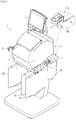
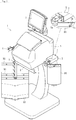
Fig. 1] Fig. 1 is a perspective view showing a blood purification apparatus according to a first embodiment of the present invention (with a hanger portion in the use position). - [
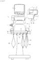
Fig. 2] Fig. 2 is a front view showing the blood purification apparatus. - [
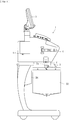
Fig. 3] Fig. 3 is a left side view showing the blood purification apparatus. - [
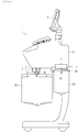
Fig. 4] Fig. 4 is a right side view showing the blood purification apparatus. - [
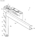
Fig. 5] Fig. 5 is a perspective view showing a holding device of the blood purification apparatus (with the hanger portion in the use position). - [
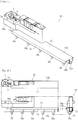
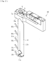
Fig. 6] Fig. 6 includes three views showing the holding device (with the hanger portion in the use position). - [
Fig. 7] Fig. 7 is a perspective view showing the blood purification apparatus (with the hanger portion in the replacement position). - [
Fig. 8] Fig. 8 is a front view showing the blood purification apparatus (with the hanger portion in the replacement position). - [
Fig. 9] Fig. 9 is a left side view showing the blood purification apparatus (with the hanger portion in the replacement position). - [
Fig. 10] Fig. 10 is a right side view showing the blood purification apparatus (with the hanger portion in the replacement position). - [
Fig. 11] Fig. 11 is a perspective view showing the holding device in the blood purification apparatus (with the hanger portion in the replacement position). - [
Fig. 12] Fig. 12 includes three views showing the holding device (with the hanger portion in the replacement position). - [
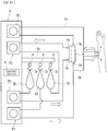
Fig. 13] Fig. 13 is a schematic view showing the blood purification apparatus. - [
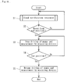
Fig. 14] Fig. 14 is a flowchart showing the content of the control of the blood purification apparatus. - [
Fig. 15] Fig. 15 is a perspective view showing a holding device of a blood purification apparatus according to a second embodiment of the present invention (with a hanger portion in the use position). - [
Fig. 16] Fig. 16 includes three views showing the holding device (with the hanger portion in the use position). - [
Fig. 17] Fig. 17 is a perspective view showing the holding device of the blood purification apparatus (with the hanger portion in the replacement position). - [
Fig. 18] Fig. 18 includes three views showing the holding device (with the hanger portion in the replacement position). - [
Fig. 19] Fig. 19 includes perspective views showing a restricting device in a blood purification apparatus according to another embodiment of the present invention. (a) is a schematic diagram showing a state where a hanger portion is in the use position. (b) is a schematic diagram showing a state where the hanger portion is in the replacement position. - Embodiments of the present invention will be described below specifically with reference to the drawings.
- A
blood purification apparatus 1 according to a first embodiment is for providing a patient with blood purification treatment (treatment such as hemodialysis (HD), hemodiafiltration (HDF), hemofiltration (HF), or continuous hemodiafiltration (CHF)), and, as shown inFigs. 1 to 13 , includes an apparatus main body A in which aholding device 2 holding container bags B1 to B3, adisplay 3, aclamping device 4, aholding device 5 holding a container bag B4, a control device H, and peristaltic pumps (P1 to P4) are formed. - The container bags B1 to B4 are bag-like containers made of nylon or the like for containing liquid for the blood purification treatment. For example, the container bag B1 contains dialysate to be supplied to a dialyzer 9 (see
Fig. 13 ), the container bag B2 contains drainage from the dialyzer 9, the container bag B3 contains substitution fluid, and the container bag B4 contains a drug administered during the blood purification treatment, such as anticoagulant. - The
display 3 is, for example, a touch panel having a liquid crystal screen or the like, and is configured to be capable of displaying the setting relating to the blood purification treatment, the state of a patient, and the like. Theclamping device 4 is capable of clamping the dialyzer 9, and is configured such that the blood of the patient can be purified by the dialyzer 9. The dialyzer 9 is formed by housing a plurality of hollow fibers with pores in a case, in which ablood inlet port 9a, ablood outlet port 9b, adialysate inlet port 9c, and adialysate outlet port 9d are formed. - The proximal end of an
arterial blood circuit 8a is connected to theblood inlet port 9a, and the proximal end of avenous blood circuit 8b is connected to theblood outlet port 9b. A blood pump, which is a peristaltic pump P1, is disposed in the middle of thearterial blood circuit 8a. An arterial puncture needle a and a venous puncture needle b that can be inserted into the patient can be attached to the distal ends of thearterial blood circuit 8a and thevenous blood circuit 8b, respectively. When, after the arterial puncture needle a and the venous puncture needle b are inserted into the patient, the peristaltic pump P1 is driven, the blood of the patient can be circulated extracorporeally through thearterial blood circuit 8a and thevenous blood circuit 8b, and blood purification by the dialyzer 9 is performed in the process of the extracorporeal circulation. - The
dialysate inlet port 9c is connected through the peristaltic pump P3 to the container bag B1. By driving the peristaltic pump P3 (dialysate pump), the dialysate in the container bag B1 can be supplied to the dialyzer 9. Thedialysate outlet port 9d is connected through the peristaltic pump P2 to the container bag B2. By driving the peristaltic pump P2 (dialysate pump), drainage from the dialyzer 9 can be contained in the container bag B2. The container bag B3 is connected through a substitution pump, which is a peristaltic pump P4, to thevenous blood circuit 8b. By driving the peristaltic pump P4, the substitution fluid in the container bag B3 can be supplied to thevenous blood circuit 8b. - The holding
device 2 is for holding the above-described container bags, and includes amain body portion 2a, ahanger portion 2b that hasattachment portions 2c to which the container bags (B1 to B3) can be attached, and that is movable between a use position in which the container bags (B1 to B3) are used (seeFigs. 1 to 6 ) and a replacement position in which the container bags (B1 to B3) are replaced (seeFigs. 7 to 12 ), and measuring devices g capable of measuring the weights of the container bags (B1 to B3) held by thehanger portion 2b (seeFig. 13 ). - The
main body portion 2a movably supports thehanger portion 2b, and includes, in this embodiment, a shaft portion L for swinging thehanger portion 2b, and a detecting device S, which is a sensor capable of detecting that the shaft portion L is in a predetermined position. That is, when thehanger portion 2b is under themain body portion 2a as shown inFigs. 5 and 6 , thehanger portion 2b is in the "use position." When thehanger portion 2b is swung about the shaft portion L, and thehanger portion 2b is in a position distant from themain body portion 2a as shown inFigs. 11 and12 , thehanger portion 2b is in the "replacement position." - The shaft portion L is a rotating shaft that rotates with the swing of the
hanger portion 2b, and a protrusion La is formed on part thereof. When thehanger portion 2b is in the use position, the protrusion La is detected by the detecting device S, and an electric signal is transmitted to the control device H. That is, it can be detected that thehanger portion 2b is in the use position, from the fact that the detecting device S is in an ON state (it can also be detected that thehanger portion 2b is not in the use position, from the fact that the detecting device S is in an OFF state). - The
hanger portion 2b is a bar-like member one end of which is attached to the shaft portion L, and hasattachment portions 2c formed at predetermined intervals. Theattachment portions 2c are hooks from which the container bags (B1 to B3) can be hung and that can hold them, and the measuring devices g are disposed at the respective proximal ends thereof. The measuring devices g are load meters that measure applied loads, and measure the weights of the container bags (B1 to B3) hung from theattachment portions 2c (the total weights of the container bags and the contents), and can transmit the measured values as electric signals to the control device H. - By measuring the weights of the container bags B1 and B2 with the measuring devices g and controlling the driving of the peristaltic pumps P2 and P3 according to the weights, dialysate can be supplied to the dialyzer 9 at a predetermined flow rate, and drainage can be discharged from the dialyzer 9 at a predetermined flow rate. By measuring the weight of the container bag B3 with the measuring device g and controlling the driving of the peristaltic pump P4 according to the weight, substitution fluid can be supplied to the
venous blood circuit 8b at a predetermined flow rate. - The holding
device 2 according to this embodiment has a restrictingdevice 6 that restricts the attachment and detachment of the container bags (B1 to B3) to and from theattachment portions 2c when thehanger portion 2b is in the use position. The restrictingdevice 6 is a shielding plate that is fixed to the apparatus main body A and that covers and shields theattachment portions 2c only when thehanger portion 2b is in the use position, and is formed, for example, by pressing a metal plate material into a substantially U shape, so as to have afront portion 6a, alower surface portion 6b, and aflange portion 6c. - That is, when the
hanger portion 2b is in the use position, as shown inFigs. 5 and 6 , thefront portion 6a, thelower surface portion 6b, and theflange portion 6c of the restrictingdevice 6 cover and shield theattachment portions 2c formed in thehanger portion 2b and restrict the attachment and detachment of the container bags (B1 to B3) to and from theattachment portions 2c (physically restrict the attachment and detachment). When thehanger portion 2b is swung from the use position to the replacement position, as shown inFigs. 11 and12 , thehanger portion 2b is distant from the restrictingdevice 6 and theattachment portions 2c are not shielded, and the attachment and detachment of the container bags (B1 to B3) to and from theattachment portions 2c are allowed. - In this embodiment, when, during the blood purification treatment, the detecting device S does not detect that the
hanger portion 2b is in the use position (that is, when thehanger portion 2b is not in the use position), it is informed that thehanger portion 2b is not in the use position. Such information may be displayed by thedisplay 3, or may be output by a speaker, a warning light, or the like (not shown). The worker can thereby reliably grasp that thehanger portion 2b is not in a position in which the container bags (B1 to B3) can be replaced (replacement position). - The control device H according to this embodiment is configured to stop the control relating to the blood purification treatment when, during the blood purification treatment, the detecting device S does not detect that the
hanger portion 2b is in the use position, and to resume the control relating to the blood purification treatment when, after the control relating to the blood purification treatment is stopped, the detecting device S detects that thehanger portion 2b is in the use position. - Since, as described above, the control relating to the blood purification treatment is stopped when, during the blood purification treatment, the detecting device S does not detect that the
hanger portion 2b is in the use position, inadvertent replacement of the container bags (B1 to B3) during the blood purification treatment can be reliably avoided. Since the control relating to the blood purification treatment is resumed when, after the control relating to the blood purification treatment is stopped, the detecting device S detects that thehanger portion 2b is in the use position, the control relating to the blood purification treatment is performed only when thehanger portion 2b is in the use position (that is, when the replacement of the container bags (B1 to B3) is restricted by the restricting device 6), and inadvertent replacement of the container bags (B1 to B3) during the blood purification treatment can be reliably avoided, and the resumption after the stop of the control relating to the blood purification treatment can be performed automatically. - In this embodiment, the container bag B4 containing a drug administered during the blood purification treatment, such as anticoagulant, is held by the holding
device 5. As with the holdingdevice 2, the holdingdevice 5 has ahanger portion 5b in which anattachment portion 5c, which is a hook, is formed. A restrictingdevice 7 that restricts the attachment and detachment of the container bag B4 to and from theattachment portion 5c when the hanger portion is in the use position as shown inFig. 2 is attached to the apparatus main body A. - Next, the content of the control by the control device H according to this embodiment will be described with reference to the flowchart of
Fig. 14 . - First, the
hanger portion 2b is set in the replacement position, the container bags (B1 to B3) are attached to theattachment portions 2c of the holdingdevice 2, the container bag B4 is attached to theattachment portion 5c of the holdingdevice 5, and then thehanger portion 2b (the same goes for thehanger portion 5b of the holding device 5) is moved to the use position and the blood purification treatment is performed (S1). - On the basis of the detection signal from the detecting device S, it is determined whether or not the
hanger portion 2b of the holdingdevice 2 is moved from the use position (S2). If thehanger portion 2b is not moved from the use position, the blood purification treatment is continued. If thehanger portion 2b is moved from the use position, the processing proceeds to S3, and the control relating to the blood purification treatment (for example, the driving of the peristaltic pumps P1 to P4 and the measurement by the measuring devices g) is stopped. - After that, on the basis of the detection signal from the detecting device S, it is determined whether or not the
hanger portion 2b of the holdingdevice 2 is moved to the use position (S4). If thehanger portion 2b is not moved to the use position, the control relating to the blood purification treatment remains stopped. If thehanger portion 2b is moved to the use position, the processing proceeds to S5, and the control relating to the blood purification treatment (for example, the driving of the peristaltic pumps P1 to P4 and the measurement by the measuring devices g) is resumed. - Since the above embodiment has the restricting
device 6 that restricts the attachment and detachment of the container bags (B1 to B3) to and from theattachment portions 2c when thehanger portion 2b is in the use position, inadvertent replacement of the container bags (B1 to B3) attached to thehanger portion 2b can be avoided. Inadvertent replacement of the container bags (B1 to B3) is physically restricted when thehanger portion 2b is in the use position. Therefore, if the measured values of the measuring devices g are abnormal when thehanger portion 2b is in the use position, it is mainly caused by a problem with theblood purification apparatus 1, such as damage to the container bags (B1 to B3). Therefore, a false alarm can be prevented. - In particular, the restricting device 6 (the same goes for the restricting device 7) according to this embodiment is a shielding plate that is fixed to the apparatus main body A and that covers and shields the
attachment portions 2c only when thehanger portion 2b is in the use position. Therefore, inadvertent replacement of the container bags (B1 to B3) when thehanger portion 2b is in the use position can be reliably avoided, and the configuration of thehanger portion 2b can be simplified. - Next, a blood purification apparatus according to a second embodiment of the present invention will be described.
- The blood purification apparatus according to this embodiment is, as with the first embodiment, for providing a patient with blood purification treatment, and, as shown in
Figs. 15 to 18 , includes a holdingdevice 10 including amain body portion 10a, ahanger portion 10b that hasattachment portions 10c to which container bags (B1 to B3) can be attached, and that is movable between a use position in which the container bags (B1 to B3) are used (seeFigs. 15 and 16 ) and a replacement position in which the container bags (B1 to B3) are replaced (seeFigs. 17 and18 ), and measuring devices g capable of measuring the weights of the container bags (B1 to B3) held by thehanger portion 10b (seeFig. 13 ). The description of the same configuration as that of the first embodiment (particularly the configuration of the apparatus main body A) will be omitted. - The
main body portion 10a movably supports thehanger portion 10b, and includes, as with the first embodiment, a shaft portion L for swinging thehanger portion 10b, and a detecting device S, which is a sensor capable of detecting that the shaft portion L is in a predetermined position. That is, when thehanger portion 10b is under themain body portion 10a as shown inFigs. 15 and 16 , thehanger portion 10b is in the "use position." When thehanger portion 10b is swung about the shaft portion L, and thehanger portion 10b is in a position distant from themain body portion 10a as shown inFigs. 17 and18 , thehanger portion 10b is in the "replacement position." - The
hanger portion 10b is a bar-like member one end of which is attached to the shaft portion L, and hasattachment portions 10c formed at predetermined intervals. Theattachment portions 10c are hooks from which the container bags (B1 to B3) can be hung and that can hold them, and the measuring devices g are disposed at the respective proximal ends thereof. The measuring devices g are load meters that measure applied loads, and measure the weights of the container bags (B1 to B3) hung from theattachment portions 10c (the total weights of the container bags and the contents), and can transmit the measured values as electric signals to the control device H. - The holding
device 10 according to this embodiment has a restrictingdevice 11 that restricts the attachment and detachment of the container bags (B1 to B3) to and from theattachment portions 10c when thehanger portion 10b is in the use position. The restrictingdevice 11 is a shielding plate that is attached to thehanger portion 10b and that is movable between a first position in which theattachment portions 10c are shielded (seeFigs. 15 and 16 ) and a second position in which theattachment portions 10c are open (seeFigs. 17 and18 ), and is movable from the first position to the second position only when thehanger portion 10b is in the replacement position. - More specifically, the restricting
device 11 according to this embodiment is formed, for example, by pressing a metal plate material into a substantially U shape, so as to have anupper surface portion 11b, and aflange portion 11c, and swings aboutshafts 11a formed on both end faces of thehanger portion 10b, and is movable between the first position and the second position. When the restrictingdevice 11 is in the first position, as shown inFig. 16 , theupper surface portion 11b and theflange portion 11c of the restrictingdevice 11 cover and shield theattachment portions 10c formed in thehanger portion 10b and restrict the attachment and detachment of the container bags (B1 to B3) to and from theattachment portions 10c (physically restrict the attachment and detachment). When the restrictingdevice 11 is swung to the second position with thehanger portion 10b in the replacement position, as shown inFig. 18 , the attachment and detachment of the container bags (B1 to B3) to and from theattachment portions 10c are allowed. If, when thehanger portion 10b is in the use position, one tries to move the restrictingdevice 11 from the first position to the second position, the restrictingdevice 11 interferes with themain body portion 10a over it and its movement is restricted. - Since the above embodiment has, as with the first embodiment, the restricting
device 11 that restricts the attachment and detachment of the container bags (B1 to B3) to and from theattachment portions 10c when thehanger portion 10b is in the use position, inadvertent replacement of the container bags (B1 to B3) attached to thehanger portion 10b can be avoided. Inadvertent replacement of the container bags (B1 to B3) is physically restricted when thehanger portion 10b is in the use position. Therefore, if the measured values of the measuring devices g are abnormal when thehanger portion 10b is in the use position, it is mainly caused by a problem with theblood purification apparatus 1, such as damage to the container bags (B1 to B3). Therefore, a false alarm can be prevented. - In particular, the restricting
device 11 according to this embodiment is a shielding plate that is attached to thehanger portion 10b and that is movable between a first position in which theattachment portions 10c are shielded and a second position in which theattachment portions 10c are open, and is movable from the first position to the second position only when thehanger portion 10b is in the replacement position. Therefore, inadvertent replacement of the container bags (B1 to B3) when thehanger portion 10b is in the use position can be reliably avoided, and the restrictingdevice 11 can be caused to follow thehanger portion 10b. - Although embodiments have been described, the present invention is not limited to them. For example, the restricting device (6, 11) that restricts the attachment and detachment of the container bags (B1 to B3) to and from the attachment portions (2c, 10c) when the hanger portion (2b, 10b) is in the use position is not limited to the shielding plates in the above-described embodiments, but may be, for example, a bar-like restricting
device 12 that is swingably attached to an attachment portion f (hook) capable of holding a container bag as shown inFig. 19 . - In this case, the weight of the container bag attached to the attachment portion f can be measured by a measuring device g. When the hanger portion of the holding device is in the use position, as shown in (a) of the figure, the swing of the restricting
device 12 is restricted by the apparatus main body M or the like, and the replacement (attachment and detachment) of the container bag to and from the attachment portion f is restricted by the restrictingdevice 12. When the hanger portion of the holding device is in the replacement position, as shown in (b) of the figure, the restrictingdevice 12 swings about ashaft 12a and the restriction by the restrictingdevice 12 is removed, and the replacement (attachment and detachment) of the container bag to and from the attachment portion f is allowed. The restrictingdevice 12 in this case has ahole 12b formed at a predetermined position thereof. In the restricting state, thehole 12b fits on the distal end of the attachment portion f as shown in (a) of the figure. - If a blood purification apparatus includes a holding device including a hanger portion including an attachment portion to which a container bag can be attached and that is movable between a use position in which the container bag is used and a replacement position in which the container bag is replaced, a measuring device capable of measuring the weight of the container bag held by the hanger portion, and a restricting device that restricts the attachment and detachment of the container bag to and from the attachment portions when the hanger portion is in the use position, the blood purification apparatus can also be applied to those which have different outer shapes or other additional functions.
-
- 1
- blood purification apparatus
- 2
- holding device
- 3
- display
- 4
- clamping device
- 5
- holding device
- 6
- restricting device
- 7
- restricting device
- 8a
- arterial blood circuit
- 8b
- venous blood circuit
- 9
- dialyzer (blood purifier)
- 10
- holding device
- 11
- restricting device
- 12
- restricting device
- B1
- to B4 container bag
Claims (6)
- A blood purification apparatus comprising a holding device capable of holding a container bag that contains a liquid for blood purification treatment, such as dialysate, substitution fluid, or anticoagulant, the blood purification apparatus being capable of performing blood purification treatment using the liquid in the container bag,
wherein the holding device includes
a hanger portion including an attachment portion to which the container bag can be attached, and movable between a use position in which the container bag is used and a replacement position in which the container bag is replaced,
a measuring device capable of measuring the weight of the container bag held by the hanger portion, and
a restricting device that restricts attachment and detachment of the container bag to and from the attachment portion when the hanger portion is in the use position. - The blood purification apparatus according to Claim 1, wherein the restricting device is a shielding plate that is fixed to an apparatus main body and that covers and shields the attachment portion only when the hanger portion is in the use position.
- The blood purification apparatus according to Claim 1, wherein the restricting device is a shielding plate that is attached to the hanger portion and that is movable between a first position in which the attachment portion is shielded and a second position in which the attachment portion is open, the restricting device being movable from the first position to the second position only when the hanger portion is in the replacement position.
- The blood purification apparatus according to any one of Claims 1 to 3, further comprising a detecting device detecting that the hanger portion is in the use position, and wherein when, during the blood purification treatment, the detecting device does not detect that the hanger portion is in the use position, it is informed that the hanger portion is not in the use position.
- The blood purification apparatus according to any one of Claims 1 to 3, further comprising a detecting device detecting that the hanger portion is in the use position, and wherein when, during the blood purification treatment, the detecting device does not detect that the hanger portion is in the use position, control relating to the blood purification treatment is stopped.
- The blood purification apparatus according to Claim 5, wherein when, after the control relating to the blood purification treatment is stopped, the detecting device detects that the hanger portion is in the use position, the control relating to the blood purification treatment is resumed.
Applications Claiming Priority (2)
| Application Number | Priority Date | Filing Date | Title |
|---|---|---|---|
| JP2014099857A JP5850980B2 (en) | 2014-05-13 | 2014-05-13 | Blood purification equipment |
| PCT/JP2015/063783 WO2015174458A1 (en) | 2014-05-13 | 2015-05-13 | Blood purification device |
Publications (3)
| Publication Number | Publication Date |
|---|---|
| EP3144021A1 true EP3144021A1 (en) | 2017-03-22 |
| EP3144021A4 EP3144021A4 (en) | 2018-01-17 |
| EP3144021B1 EP3144021B1 (en) | 2020-10-28 |
Family
ID=54479995
Family Applications (1)
| Application Number | Title | Priority Date | Filing Date |
|---|---|---|---|
| EP15792192.5A Active EP3144021B1 (en) | 2014-05-13 | 2015-05-13 | Blood purification device |
Country Status (5)
| Country | Link |
|---|---|
| US (1) | US10471202B2 (en) |
| EP (1) | EP3144021B1 (en) |
| JP (1) | JP5850980B2 (en) |
| CN (1) | CN106456862B (en) |
| WO (1) | WO2015174458A1 (en) |
Families Citing this family (5)
| Publication number | Priority date | Publication date | Assignee | Title |
|---|---|---|---|---|
| CN109865169A (en) * | 2019-03-15 | 2019-06-11 | 常州市第二人民医院 | The hemodialyzer of alarm function after a kind of empty bottle with blood vial |
| US11517653B2 (en) * | 2019-11-05 | 2022-12-06 | Diality Inc. | Hemodialysis system reservoir level sensor |
| US12521473B2 (en) | 2019-11-05 | 2026-01-13 | Diality Inc. | Hemodialysis system reservoir level sensor |
| CN113577424B (en) * | 2021-08-20 | 2024-07-05 | 北京健帆医疗设备有限公司 | Waste liquid discharge method for blood purification apparatus, and storage medium |
| CN118500515A (en) * | 2024-06-06 | 2024-08-16 | 南京汉科明德医疗科技有限公司 | Weighing system for blood purification, use method and continuous blood purification equipment |
Family Cites Families (8)
| Publication number | Priority date | Publication date | Assignee | Title |
|---|---|---|---|---|
| JPH11128342A (en) * | 1997-10-27 | 1999-05-18 | Meteku:Kk | Peritoneal dialysis liquid metabolic device |
| US7591945B2 (en) * | 2003-02-07 | 2009-09-22 | Gambro Lundia Ab | Support device for containers in extracorporeal blood treatment machines |
| ITMI20030216A1 (en) * | 2003-02-07 | 2004-08-08 | Gambro Lundia Ab | SUPPORT DEVICE FOR CONTAINERS IN MACHINES FOR THE EXTRACORPOREAL BLOOD TREATMENT OR IN MACHINES FOR THE TREATMENT OF RENAL INSUFFICIENCY. |
| DE102004048911C5 (en) * | 2004-10-06 | 2009-04-30 | Fresenius Medical Care Deutschland Gmbh | Blood treatment device with rod-like means for holding objects |
| JP4853957B2 (en) * | 2006-06-22 | 2012-01-11 | 日機装株式会社 | Hanger for fluid replacement bag |
| JP2009131595A (en) * | 2007-11-05 | 2009-06-18 | Nippo Sewing Mach Kk | Infusion container holder |
| FR2925341A1 (en) * | 2007-12-20 | 2009-06-26 | Gambro Lundia Ab | APPARATUS FOR THE EXTRACORPOREAL TREATMENT OF BLOOD OR PLASMA RECEIVING MULTIPLE ARTICLES FOR SINGLE USE |
| US8403875B2 (en) * | 2008-10-15 | 2013-03-26 | B. Braun Avitum Ag | Bag hanger assembly for blood therapy apparatus |
-
2014
- 2014-05-13 JP JP2014099857A patent/JP5850980B2/en active Active
-
2015
- 2015-05-13 WO PCT/JP2015/063783 patent/WO2015174458A1/en not_active Ceased
- 2015-05-13 EP EP15792192.5A patent/EP3144021B1/en active Active
- 2015-05-13 CN CN201580024697.9A patent/CN106456862B/en active Active
-
2016
- 2016-11-04 US US15/343,652 patent/US10471202B2/en active Active
Also Published As
| Publication number | Publication date |
|---|---|
| US10471202B2 (en) | 2019-11-12 |
| JP2015213698A (en) | 2015-12-03 |
| WO2015174458A1 (en) | 2015-11-19 |
| JP5850980B2 (en) | 2016-02-03 |
| US20170072126A1 (en) | 2017-03-16 |
| EP3144021B1 (en) | 2020-10-28 |
| CN106456862B (en) | 2019-04-23 |
| EP3144021A4 (en) | 2018-01-17 |
| CN106456862A (en) | 2017-02-22 |
Similar Documents
| Publication | Publication Date | Title |
|---|---|---|
| US10471202B2 (en) | Blood purification apparatus | |
| EP3248629B1 (en) | Blood purification device | |
| US8403875B2 (en) | Bag hanger assembly for blood therapy apparatus | |
| CA3100217C (en) | Calculation of the patient fluid removal rate to compensate for the volume of fluid not removed because of machine down times | |
| CN107106752B (en) | Method, medical device and computer program for displaying predicted state | |
| JP5433634B2 (en) | Blood purification equipment | |
| EP3407933B1 (en) | Solution infusion apparatus, particularly for dialysis systems | |
| WO2012169610A1 (en) | Blood purification device | |
| CN113577424B (en) | Waste liquid discharge method for blood purification apparatus, and storage medium | |
| US20180326137A1 (en) | Extracorporeal blood treatment apparatus with reservoir status lights | |
| EP3621673B1 (en) | Infusion methods for extracoporeal systems | |
| ITMO20100270A1 (en) | WEARABLE SYSTEM TO CARRY OUT PURIFYING THERAPIES OF ORGANIC FLUIDS WITH THE USE OF EXTRACORPY CIRCUITS | |
| US20200093975A1 (en) | Blood Purification Apparatus | |
| JP5990312B2 (en) | Blood purification equipment | |
| EP3622980B1 (en) | Blood purification apparatus | |
| CA3069229C (en) | Infusion methods for extracorporeal systems | |
| CN107961419A (en) | Liquid level detection system |
Legal Events
| Date | Code | Title | Description |
|---|---|---|---|
| STAA | Information on the status of an ep patent application or granted ep patent |
Free format text: STATUS: THE INTERNATIONAL PUBLICATION HAS BEEN MADE |
|
| PUAI | Public reference made under article 153(3) epc to a published international application that has entered the european phase |
Free format text: ORIGINAL CODE: 0009012 |
|
| STAA | Information on the status of an ep patent application or granted ep patent |
Free format text: STATUS: REQUEST FOR EXAMINATION WAS MADE |
|
| 17P | Request for examination filed |
Effective date: 20161130 |
|
| AK | Designated contracting states |
Kind code of ref document: A1 Designated state(s): AL AT BE BG CH CY CZ DE DK EE ES FI FR GB GR HR HU IE IS IT LI LT LU LV MC MK MT NL NO PL PT RO RS SE SI SK SM TR |
|
| AX | Request for extension of the european patent |
Extension state: BA ME |
|
| DAV | Request for validation of the european patent (deleted) | ||
| DAX | Request for extension of the european patent (deleted) | ||
| A4 | Supplementary search report drawn up and despatched |
Effective date: 20171220 |
|
| RIC1 | Information provided on ipc code assigned before grant |
Ipc: A61M 5/14 20060101ALI20171214BHEP Ipc: A61M 1/14 20060101AFI20171214BHEP Ipc: A61M 5/168 20060101ALI20171214BHEP Ipc: A61M 1/16 20060101ALI20171214BHEP |
|
| STAA | Information on the status of an ep patent application or granted ep patent |
Free format text: STATUS: EXAMINATION IS IN PROGRESS |
|
| R17P | Request for examination filed (corrected) |
Effective date: 20161130 |
|
| 17Q | First examination report despatched |
Effective date: 20200228 |
|
| GRAP | Despatch of communication of intention to grant a patent |
Free format text: ORIGINAL CODE: EPIDOSNIGR1 |
|
| STAA | Information on the status of an ep patent application or granted ep patent |
Free format text: STATUS: GRANT OF PATENT IS INTENDED |
|
| INTG | Intention to grant announced |
Effective date: 20200731 |
|
| GRAS | Grant fee paid |
Free format text: ORIGINAL CODE: EPIDOSNIGR3 |
|
| GRAA | (expected) grant |
Free format text: ORIGINAL CODE: 0009210 |
|
| STAA | Information on the status of an ep patent application or granted ep patent |
Free format text: STATUS: THE PATENT HAS BEEN GRANTED |
|
| AK | Designated contracting states |
Kind code of ref document: B1 Designated state(s): AL AT BE BG CH CY CZ DE DK EE ES FI FR GB GR HR HU IE IS IT LI LT LU LV MC MK MT NL NO PL PT RO RS SE SI SK SM TR |
|
| REG | Reference to a national code |
Ref country code: GB Ref legal event code: FG4D |
|
| REG | Reference to a national code |
Ref country code: CH Ref legal event code: EP |
|
| REG | Reference to a national code |
Ref country code: DE Ref legal event code: R096 Ref document number: 602015061198 Country of ref document: DE |
|
| REG | Reference to a national code |
Ref country code: AT Ref legal event code: REF Ref document number: 1327557 Country of ref document: AT Kind code of ref document: T Effective date: 20201115 |
|
| REG | Reference to a national code |
Ref country code: IE Ref legal event code: FG4D |
|
| REG | Reference to a national code |
Ref country code: AT Ref legal event code: MK05 Ref document number: 1327557 Country of ref document: AT Kind code of ref document: T Effective date: 20201028 |
|
| REG | Reference to a national code |
Ref country code: NL Ref legal event code: MP Effective date: 20201028 |
|
| PG25 | Lapsed in a contracting state [announced via postgrant information from national office to epo] |
Ref country code: FI Free format text: LAPSE BECAUSE OF FAILURE TO SUBMIT A TRANSLATION OF THE DESCRIPTION OR TO PAY THE FEE WITHIN THE PRESCRIBED TIME-LIMIT Effective date: 20201028 Ref country code: RS Free format text: LAPSE BECAUSE OF FAILURE TO SUBMIT A TRANSLATION OF THE DESCRIPTION OR TO PAY THE FEE WITHIN THE PRESCRIBED TIME-LIMIT Effective date: 20201028 Ref country code: PT Free format text: LAPSE BECAUSE OF FAILURE TO SUBMIT A TRANSLATION OF THE DESCRIPTION OR TO PAY THE FEE WITHIN THE PRESCRIBED TIME-LIMIT Effective date: 20210301 Ref country code: NL Free format text: LAPSE BECAUSE OF FAILURE TO SUBMIT A TRANSLATION OF THE DESCRIPTION OR TO PAY THE FEE WITHIN THE PRESCRIBED TIME-LIMIT Effective date: 20201028 Ref country code: NO Free format text: LAPSE BECAUSE OF FAILURE TO SUBMIT A TRANSLATION OF THE DESCRIPTION OR TO PAY THE FEE WITHIN THE PRESCRIBED TIME-LIMIT Effective date: 20210128 Ref country code: GR Free format text: LAPSE BECAUSE OF FAILURE TO SUBMIT A TRANSLATION OF THE DESCRIPTION OR TO PAY THE FEE WITHIN THE PRESCRIBED TIME-LIMIT Effective date: 20210129 |
|
| REG | Reference to a national code |
Ref country code: LT Ref legal event code: MG4D |
|
| PG25 | Lapsed in a contracting state [announced via postgrant information from national office to epo] |
Ref country code: AT Free format text: LAPSE BECAUSE OF FAILURE TO SUBMIT A TRANSLATION OF THE DESCRIPTION OR TO PAY THE FEE WITHIN THE PRESCRIBED TIME-LIMIT Effective date: 20201028 Ref country code: ES Free format text: LAPSE BECAUSE OF FAILURE TO SUBMIT A TRANSLATION OF THE DESCRIPTION OR TO PAY THE FEE WITHIN THE PRESCRIBED TIME-LIMIT Effective date: 20201028 Ref country code: BG Free format text: LAPSE BECAUSE OF FAILURE TO SUBMIT A TRANSLATION OF THE DESCRIPTION OR TO PAY THE FEE WITHIN THE PRESCRIBED TIME-LIMIT Effective date: 20210128 Ref country code: PL Free format text: LAPSE BECAUSE OF FAILURE TO SUBMIT A TRANSLATION OF THE DESCRIPTION OR TO PAY THE FEE WITHIN THE PRESCRIBED TIME-LIMIT Effective date: 20201028 Ref country code: IS Free format text: LAPSE BECAUSE OF FAILURE TO SUBMIT A TRANSLATION OF THE DESCRIPTION OR TO PAY THE FEE WITHIN THE PRESCRIBED TIME-LIMIT Effective date: 20210228 Ref country code: LV Free format text: LAPSE BECAUSE OF FAILURE TO SUBMIT A TRANSLATION OF THE DESCRIPTION OR TO PAY THE FEE WITHIN THE PRESCRIBED TIME-LIMIT Effective date: 20201028 |
|
| PG25 | Lapsed in a contracting state [announced via postgrant information from national office to epo] |
Ref country code: HR Free format text: LAPSE BECAUSE OF FAILURE TO SUBMIT A TRANSLATION OF THE DESCRIPTION OR TO PAY THE FEE WITHIN THE PRESCRIBED TIME-LIMIT Effective date: 20201028 |
|
| REG | Reference to a national code |
Ref country code: DE Ref legal event code: R097 Ref document number: 602015061198 Country of ref document: DE |
|
| PG25 | Lapsed in a contracting state [announced via postgrant information from national office to epo] |
Ref country code: LT Free format text: LAPSE BECAUSE OF FAILURE TO SUBMIT A TRANSLATION OF THE DESCRIPTION OR TO PAY THE FEE WITHIN THE PRESCRIBED TIME-LIMIT Effective date: 20201028 Ref country code: SK Free format text: LAPSE BECAUSE OF FAILURE TO SUBMIT A TRANSLATION OF THE DESCRIPTION OR TO PAY THE FEE WITHIN THE PRESCRIBED TIME-LIMIT Effective date: 20201028 Ref country code: RO Free format text: LAPSE BECAUSE OF FAILURE TO SUBMIT A TRANSLATION OF THE DESCRIPTION OR TO PAY THE FEE WITHIN THE PRESCRIBED TIME-LIMIT Effective date: 20201028 Ref country code: SM Free format text: LAPSE BECAUSE OF FAILURE TO SUBMIT A TRANSLATION OF THE DESCRIPTION OR TO PAY THE FEE WITHIN THE PRESCRIBED TIME-LIMIT Effective date: 20201028 Ref country code: CZ Free format text: LAPSE BECAUSE OF FAILURE TO SUBMIT A TRANSLATION OF THE DESCRIPTION OR TO PAY THE FEE WITHIN THE PRESCRIBED TIME-LIMIT Effective date: 20201028 Ref country code: EE Free format text: LAPSE BECAUSE OF FAILURE TO SUBMIT A TRANSLATION OF THE DESCRIPTION OR TO PAY THE FEE WITHIN THE PRESCRIBED TIME-LIMIT Effective date: 20201028 |
|
| PG25 | Lapsed in a contracting state [announced via postgrant information from national office to epo] |
Ref country code: DK Free format text: LAPSE BECAUSE OF FAILURE TO SUBMIT A TRANSLATION OF THE DESCRIPTION OR TO PAY THE FEE WITHIN THE PRESCRIBED TIME-LIMIT Effective date: 20201028 |
|
| PLBE | No opposition filed within time limit |
Free format text: ORIGINAL CODE: 0009261 |
|
| STAA | Information on the status of an ep patent application or granted ep patent |
Free format text: STATUS: NO OPPOSITION FILED WITHIN TIME LIMIT |
|
| 26N | No opposition filed |
Effective date: 20210729 |
|
| PG25 | Lapsed in a contracting state [announced via postgrant information from national office to epo] |
Ref country code: AL Free format text: LAPSE BECAUSE OF FAILURE TO SUBMIT A TRANSLATION OF THE DESCRIPTION OR TO PAY THE FEE WITHIN THE PRESCRIBED TIME-LIMIT Effective date: 20201028 |
|
| PG25 | Lapsed in a contracting state [announced via postgrant information from national office to epo] |
Ref country code: SI Free format text: LAPSE BECAUSE OF FAILURE TO SUBMIT A TRANSLATION OF THE DESCRIPTION OR TO PAY THE FEE WITHIN THE PRESCRIBED TIME-LIMIT Effective date: 20201028 |
|
| REG | Reference to a national code |
Ref country code: CH Ref legal event code: PL |
|
| PG25 | Lapsed in a contracting state [announced via postgrant information from national office to epo] |
Ref country code: LI Free format text: LAPSE BECAUSE OF NON-PAYMENT OF DUE FEES Effective date: 20210531 Ref country code: MC Free format text: LAPSE BECAUSE OF FAILURE TO SUBMIT A TRANSLATION OF THE DESCRIPTION OR TO PAY THE FEE WITHIN THE PRESCRIBED TIME-LIMIT Effective date: 20201028 Ref country code: LU Free format text: LAPSE BECAUSE OF NON-PAYMENT OF DUE FEES Effective date: 20210513 Ref country code: CH Free format text: LAPSE BECAUSE OF NON-PAYMENT OF DUE FEES Effective date: 20210531 |
|
| REG | Reference to a national code |
Ref country code: BE Ref legal event code: MM Effective date: 20210531 |
|
| PG25 | Lapsed in a contracting state [announced via postgrant information from national office to epo] |
Ref country code: IE Free format text: LAPSE BECAUSE OF NON-PAYMENT OF DUE FEES Effective date: 20210513 |
|
| PG25 | Lapsed in a contracting state [announced via postgrant information from national office to epo] |
Ref country code: IS Free format text: LAPSE BECAUSE OF FAILURE TO SUBMIT A TRANSLATION OF THE DESCRIPTION OR TO PAY THE FEE WITHIN THE PRESCRIBED TIME-LIMIT Effective date: 20210228 |
|
| PG25 | Lapsed in a contracting state [announced via postgrant information from national office to epo] |
Ref country code: BE Free format text: LAPSE BECAUSE OF NON-PAYMENT OF DUE FEES Effective date: 20210531 |
|
| PG25 | Lapsed in a contracting state [announced via postgrant information from national office to epo] |
Ref country code: HU Free format text: LAPSE BECAUSE OF FAILURE TO SUBMIT A TRANSLATION OF THE DESCRIPTION OR TO PAY THE FEE WITHIN THE PRESCRIBED TIME-LIMIT; INVALID AB INITIO Effective date: 20150513 |
|
| P01 | Opt-out of the competence of the unified patent court (upc) registered |
Effective date: 20230523 |
|
| PG25 | Lapsed in a contracting state [announced via postgrant information from national office to epo] |
Ref country code: CY Free format text: LAPSE BECAUSE OF FAILURE TO SUBMIT A TRANSLATION OF THE DESCRIPTION OR TO PAY THE FEE WITHIN THE PRESCRIBED TIME-LIMIT Effective date: 20201028 |
|
| PG25 | Lapsed in a contracting state [announced via postgrant information from national office to epo] |
Ref country code: MK Free format text: LAPSE BECAUSE OF FAILURE TO SUBMIT A TRANSLATION OF THE DESCRIPTION OR TO PAY THE FEE WITHIN THE PRESCRIBED TIME-LIMIT Effective date: 20201028 |
|
| PG25 | Lapsed in a contracting state [announced via postgrant information from national office to epo] |
Ref country code: TR Free format text: LAPSE BECAUSE OF FAILURE TO SUBMIT A TRANSLATION OF THE DESCRIPTION OR TO PAY THE FEE WITHIN THE PRESCRIBED TIME-LIMIT Effective date: 20201028 |
|
| PG25 | Lapsed in a contracting state [announced via postgrant information from national office to epo] |
Ref country code: MT Free format text: LAPSE BECAUSE OF FAILURE TO SUBMIT A TRANSLATION OF THE DESCRIPTION OR TO PAY THE FEE WITHIN THE PRESCRIBED TIME-LIMIT Effective date: 20201028 |
|
| PGFP | Annual fee paid to national office [announced via postgrant information from national office to epo] |
Ref country code: DE Payment date: 20250521 Year of fee payment: 11 |
|
| PGFP | Annual fee paid to national office [announced via postgrant information from national office to epo] |
Ref country code: GB Payment date: 20250521 Year of fee payment: 11 |
|
| PGFP | Annual fee paid to national office [announced via postgrant information from national office to epo] |
Ref country code: IT Payment date: 20250527 Year of fee payment: 11 |
|
| PGFP | Annual fee paid to national office [announced via postgrant information from national office to epo] |
Ref country code: FR Payment date: 20250528 Year of fee payment: 11 |
|
| PGFP | Annual fee paid to national office [announced via postgrant information from national office to epo] |
Ref country code: SE Payment date: 20250521 Year of fee payment: 11 |