EP3142743B1 - Système de puissance rf à distance ayant une antenne d'émission à profil bas - Google Patents
Système de puissance rf à distance ayant une antenne d'émission à profil bas Download PDFInfo
- Publication number
- EP3142743B1 EP3142743B1 EP15793285.6A EP15793285A EP3142743B1 EP 3142743 B1 EP3142743 B1 EP 3142743B1 EP 15793285 A EP15793285 A EP 15793285A EP 3142743 B1 EP3142743 B1 EP 3142743B1
- Authority
- EP
- European Patent Office
- Prior art keywords
- antenna
- antenna assembly
- electromagnetic energy
- waveguide
- radiating surface
- Prior art date
- Legal status (The legal status is an assumption and is not a legal conclusion. Google has not performed a legal analysis and makes no representation as to the accuracy of the status listed.)
- Active
Links
Images


Classifications
-
- A—HUMAN NECESSITIES
- A61—MEDICAL OR VETERINARY SCIENCE; HYGIENE
- A61N—ELECTROTHERAPY; MAGNETOTHERAPY; RADIATION THERAPY; ULTRASOUND THERAPY
- A61N1/00—Electrotherapy; Circuits therefor
- A61N1/18—Applying electric currents by contact electrodes
- A61N1/32—Applying electric currents by contact electrodes alternating or intermittent currents
- A61N1/36—Applying electric currents by contact electrodes alternating or intermittent currents for stimulation
- A61N1/372—Arrangements in connection with the implantation of stimulators
- A61N1/37211—Means for communicating with stimulators
- A61N1/37217—Means for communicating with stimulators characterised by the communication link, e.g. acoustic or tactile
- A61N1/37223—Circuits for electromagnetic coupling
- A61N1/37229—Shape or location of the implanted or external antenna
-
- A—HUMAN NECESSITIES
- A61—MEDICAL OR VETERINARY SCIENCE; HYGIENE
- A61N—ELECTROTHERAPY; MAGNETOTHERAPY; RADIATION THERAPY; ULTRASOUND THERAPY
- A61N1/00—Electrotherapy; Circuits therefor
- A61N1/18—Applying electric currents by contact electrodes
- A61N1/32—Applying electric currents by contact electrodes alternating or intermittent currents
- A61N1/36—Applying electric currents by contact electrodes alternating or intermittent currents for stimulation
- A61N1/3605—Implantable neurostimulators for stimulating central or peripheral nerve system
- A61N1/36125—Details of circuitry or electric components
-
- A—HUMAN NECESSITIES
- A61—MEDICAL OR VETERINARY SCIENCE; HYGIENE
- A61N—ELECTROTHERAPY; MAGNETOTHERAPY; RADIATION THERAPY; ULTRASOUND THERAPY
- A61N1/00—Electrotherapy; Circuits therefor
- A61N1/18—Applying electric currents by contact electrodes
- A61N1/32—Applying electric currents by contact electrodes alternating or intermittent currents
- A61N1/36—Applying electric currents by contact electrodes alternating or intermittent currents for stimulation
- A61N1/3605—Implantable neurostimulators for stimulating central or peripheral nerve system
- A61N1/36128—Control systems
- A61N1/36146—Control systems specified by the stimulation parameters
-
- A—HUMAN NECESSITIES
- A61—MEDICAL OR VETERINARY SCIENCE; HYGIENE
- A61N—ELECTROTHERAPY; MAGNETOTHERAPY; RADIATION THERAPY; ULTRASOUND THERAPY
- A61N1/00—Electrotherapy; Circuits therefor
- A61N1/18—Applying electric currents by contact electrodes
- A61N1/32—Applying electric currents by contact electrodes alternating or intermittent currents
- A61N1/36—Applying electric currents by contact electrodes alternating or intermittent currents for stimulation
- A61N1/372—Arrangements in connection with the implantation of stimulators
- A61N1/37211—Means for communicating with stimulators
- A61N1/37252—Details of algorithms or data aspects of communication system, e.g. handshaking, transmitting specific data or segmenting data
-
- A—HUMAN NECESSITIES
- A61—MEDICAL OR VETERINARY SCIENCE; HYGIENE
- A61N—ELECTROTHERAPY; MAGNETOTHERAPY; RADIATION THERAPY; ULTRASOUND THERAPY
- A61N1/00—Electrotherapy; Circuits therefor
- A61N1/18—Applying electric currents by contact electrodes
- A61N1/32—Applying electric currents by contact electrodes alternating or intermittent currents
- A61N1/36—Applying electric currents by contact electrodes alternating or intermittent currents for stimulation
- A61N1/372—Arrangements in connection with the implantation of stimulators
- A61N1/378—Electrical supply
- A61N1/3787—Electrical supply from an external energy source
-
- H—ELECTRICITY
- H01—ELECTRIC ELEMENTS
- H01Q—ANTENNAS, i.e. RADIO AERIALS
- H01Q13/00—Waveguide horns or mouths; Slot antennas; Leaky-waveguide antennas; Equivalent structures causing radiation along the transmission path of a guided wave
-
- H—ELECTRICITY
- H01—ELECTRIC ELEMENTS
- H01Q—ANTENNAS, i.e. RADIO AERIALS
- H01Q9/00—Electrically-short antennas having dimensions not more than twice the operating wavelength and consisting of conductive active radiating elements
- H01Q9/04—Resonant antennas
- H01Q9/16—Resonant antennas with feed intermediate between the extremities of the antenna, e.g. centre-fed dipole
- H01Q9/26—Resonant antennas with feed intermediate between the extremities of the antenna, e.g. centre-fed dipole with folded element or elements, the folded parts being spaced apart a small fraction of operating wavelength
-
- H—ELECTRICITY
- H01—ELECTRIC ELEMENTS
- H01Q—ANTENNAS, i.e. RADIO AERIALS
- H01Q9/00—Electrically-short antennas having dimensions not more than twice the operating wavelength and consisting of conductive active radiating elements
- H01Q9/04—Resonant antennas
- H01Q9/16—Resonant antennas with feed intermediate between the extremities of the antenna, e.g. centre-fed dipole
- H01Q9/28—Conical, cylindrical, cage, strip, gauze, or like elements having an extended radiating surface; Elements comprising two conical surfaces having collinear axes and adjacent apices and fed by two-conductor transmission lines
- H01Q9/285—Planar dipole
Definitions
- This application generally relates to a RF stimulation system including an antenna assembly to remotely provide power and stimulation parameters to an implantable device.
- Antennas have been designed and utilized with implanted devices to aid in the treatment of various medical conditions. Often, these antennas are placed close to the patient's body. In some cases, the conductive element of the antennas would be subject to excessive absorption of electromagnetic energy, which, when these antennas are placed close to the patient's body, could lead to adverse events such as burning of tissue, creation of undesirable blood clots and skin irritation from adherence of the antenna directly to skin tissue.
- the system includes a catheter device including one or more energy waveguides.
- the energy waveguides can include e.g. electromagnetic waveguides, acoustic energy waveguides (e.g., ultrasonic energy waveguides), thermal energy waveguides, optical energy waveguides (e.g., optical fibers, photonic-crystal fibers, or the like), ultrasonnd energy waveguides, multi -energy waveguides, or the like.
- the energy waveguides can include lens structures, light-diffusing structures, mirror structures, mirrored surfaces, reflective coatings, reflective materials, reflective surfaces, or combinations thereof.
- US patent application US 2013/0066400 A1 describes a system including a controller module.
- the controller module includes a storage device, a controller, a modulator, and one or more antennas.
- the storage device is stored with parameters defining a stimulation waveform.
- the controller is configured to generate, based on the stored parameters, an output signal that includes the stimulation waveform, wherein the output signal additionally includes polarity assignments for electrodes in an implantable, passive stimulation device.
- the modulator modulates a stimulus carrier signal with the output signal to generate a transmission signal.
- the one or more antennas transmit the transmission signal to the implantable, passive stimulation device such that the implantable, passive stimulation device uses energy in the transmission signal for operation, sets the polarities for the electrodes in the implantable, passive stimulation device based on the encoded polarity assignments, generates electrical pulses using the stimulation waveform, and applies the electrical pulses to excitable tissue.
- US2014047713 discloses a resonator which involves positioning a conductor between insulators such that the wire structure is capable of propagating an electrical signal through a skin depth within the conductor.
- some implementations provide antenna assembly, including: an antenna that includes: a metal signal layer having a radiating surface; and a feed port; and a waveguide surrounding the antenna and configured to guide electromagnetic energy transmitted from the radiating surface in a direction away from the antenna; and a controller module connected to the feed port and configured to drive the antenna to transmit electromagnetic energy from the radiating surface; wherein the antenna, waveguide, and controller module are configured such that, when the controller module drives the antenna, the transmitted electromagnetic energy matches a reception characteristic of an implantable device and is sufficient for the implantable device to create one or more electrical pulses of sufficient amplitude to stimulate neural tissue of a patient, solely using electromagnetic energy received from the antenna, when the implantable device is located at least 10 centimeters away from the antenna.
- the implantable device includes a dipole antenna located on the implantable device inside the patient, and the radiating surface is adjustable from a first spatial orientation to a second spatial orientation such that polarized electromagnetic energy received at the dipole antenna is increased.
- the antenna assembly may further include a dielectric lens that fills the wave guide and protrude outward from an opening of the wave guide to form a protrusion that is shaped to spatially narrow the transmitted electromagnetic energy in the direction away from the transmitting surface.
- the protrusion may be tapered in shape.
- the protrusion may be tapered to have a Gaussian or sinusoid profile.
- the antenna assembly may have a return loss cutoff frequency associated with the wave guide and the dielectric lens may be further configured to lower the return loss cutoff frequency.
- the antenna may be operable within a frequency band from about 500MHz to about 4GHz.
- the radiating surface may be bowtie shaped and has two leaf structures connecting to each other at the feed port as well as through two substantially parallel rod structures.
- the transmitted electromagnetic energy may be polarized along a long axis of the rod structures.
- the radiating surface may be adjustable from a first spatial orientation to a second spatial orientation such that polarized electromagnetic energy received at the implantable device is increased.
- the waveguide may be a rectangular waveguide having four walls that surround the bowtie shaped radiating surface.
- the rectangular waveguide may have an interior length of about 15cm, an interior width of about 7.6cm, and a height of about 5cm.
- the rectangular waveguide may have an interior length of at least 10cm, and the rectangular waveguide may have an interior length, width, and height ratio of about 15:7.6:5.
- some implementations may include a method for wirelessly supplying energy to an implantable device, the method including: radiating electromagnetic energy from a radiating surface on an antenna assembly, the radiated electromagnetic energy reaching an implantable device located at least 10 centimeters away and implanted inside a patient such that the implantable device creates, solely by using the radiated electromagnetic energy, one or more electrical stimulation pulses suitable for stimulating neural tissue of the patient, and applies the electrical stimulation pulses to neural tissue of the patient.
- Radiating the electromagnetic energy may further include radiating the electromagnetic energy while the patient is asleep such that the created one or more electrical simulation pulses is applied to stimulate the patient's neural tissue during the patient's sleep.
- the method may further include: adjusting a position of the antenna assembly such that the radiating surface of the antenna assembly is no more than six feet from the implantable device.
- the method may further include: adjusting a position of the antenna assembly such that the radiating surface of the antenna assembly is no less than one foot from the implantable device.
- the method may further include: adjusting an orientation of the antenna assembly such that the radiated electromagnetic energy received at the implantable device is increased.
- the method may further include: connecting the antenna assembly to a controller module; and driving the antenna assembly from the controller module connected thereto such that the radiating surface on the antenna assembly radiates electromagnetic energy to power the implantable.
- the method may further include establishing a link between a programming module to the controller module; and transmitting, from the programming module to the controller module, data encoding parameters of the one or more stimulation pulses to be created at the implantable device and to be subsequently applied to stimulate the patient's neural tissue.
- some implementations may include a system that includes: an antenna assembly that wirelessly powers an implantable device, the antenna assembly including: an antenna that includes: a metal signal layer having a radiating surface and configured to transmit electromagnetic energy via radiative coupling; a waveguide surrounding the antenna and configured to guide electromagnetic energy transmitted from the radiating surface in a direction away from the antenna; and; a controller module connected to the feed port of the antenna and configured to drive the antenna assembly such that the radiating surface on the antenna radiates electromagnetic energy.
- Implementations may include one or more of the following features.
- the system may further include an implantable operable from a location inside a patient and more than 10 centimeters away from the antenna assembly, wherein the implantable device creates one or more stimulation pulses of sufficient amplitude to stimulate neural tissue of the patient solely using electromagnetic energy received from the antenna assembly .
- the waveguide may be a rectangular waveguide having four walls that surround the radiating surface.
- the rectangular waveguide may have an interior length of about 15cm, an interior width of about 7.6cm, and a height of about 5cm.
- the rectangular waveguide mayhong an interior length of at least 10cm, and the rectangular waveguide may have an interior length, width, and height ratio of about 15:7.6:5.
- the system may further include a dielectric lens that fills the wave guide and protrude outward from an opening of the wave guide to form a protrusion that is shaped to spatially narrow the transmitted electromagnetic energy in the direction away from the transmitting surface.
- the protrusion may be tapered in shape.
- the protrusion may be tapered to have a Gaussian or sinusoid profile.
- the antenna may be operable within a frequency band from about 500MHz to about 4GHz.
- the radiating surface may be bowtie shaped and has two leaf structures connecting to each other at the feed port as well as through two substantially parallel rod structures.
- the transmitted electromagnetic energy may be polarized along a long axis of the rod structures.
- a device may be used to send electrical energy to targeted nerve tissue by using remote radio frequency (RF) energy without cables or inductive coupling to power a passive implanted wireless stimulator device.
- RF radio frequency
- the targeted nerves can include, but are not limited to, the spinal cord and surrounding areas, including the dorsal horn, dorsal root ganglion, the exiting nerve roots, nerve ganglions, the dorsal column fibers and the peripheral nerve bundles leaving the dorsal column and brain, such as the vagus, occipital, trigeminal, hypoglossal, sacral, coccygeal nerves and the like.
- a wireless stimulation system can include an implantable stimulator device with one or more electrodes and one or more conductive antennas (for example, dipole or patch antennas), and internal circuitry for frequency waveform and electrical energy rectification.
- the system may further comprise an external controller and antenna for transmitting radio frequency or microwave energy from an external source to the implantable stimulator device with neither cables nor inductive coupling to provide power.
- the wireless implantable stimulator device is powered wirelessly (and therefore does not require a wired connection) and contains the circuitry necessary to receive the pulse instructions from a source external to the body.
- various embodiments employ internal dipole (or other) antenna configuration(s) to receive RF power through electrical radiative coupling. This allows such devices to produce electrical currents capable of stimulating nerve bundles without a physical connection to an implantable pulse generator (IPG) or use of an inductive coil.
- IPG implantable pulse generator
- Antennas can be designed for the purpose of transmitting microwave energy to a receiving antenna located just below a patient's skin, or on the skin, from a distant location (e.g., of up to four to six feet and stationary).
- the antenna design may be dependent on the mobility needs of the patient while receiving the therapy.
- the antenna may advantageously have a minimum profile so that the antenna can blend in with the ambience of the room.
- the disclosure focuses on the design of a compact remote transmitting antenna with superior matching and gain, as well as being several orders of magnitude less expensive than comparable antennas and very easy to manufacture.
- a wireless stimulation system can include an antenna assembly coupled to a controller module and configured to radiate electromagnetic energy to an implantable device.
- the implantable device can be a passive neural stimulator device configured to receive RF energy and stimulation parameters wirelessly. Solely by using the received electromagnetic energy, the implantable passive neural stimulator creates one or more stimulation pulses to stimulate neural tissue of a patient.
- the antenna assembly can include an antenna with a bowtie-shaped radiating surface and a feed port. The feed port may be coupled to a controller module that drives the antenna to transmit the electromagnetic energy from the bowtie radiating surface.
- the bowtie shaped radiating surface is generally sized and shaped to radiate the electromagnetic energy to match a reception characteristic of the implantable passive neural stimulator.
- the implantable passive neural stimulator includes a dipole antenna and the radiating surface is configured to transmit polarized electromagnetic energy commensurate with dipole reception characteristics.
- the antenna assembly may further include a wave guide that surrounds the antenna to direct the transmitted electromagnetic energy away from the radiating surface.
- a dielectric lens fills the waveguide and extend outward from an opening of the wave guide to form a protrusion.
- the protrusion is shaped to spatially narrow the transmitted electromagnetic energy in the direction away from the transmitting surface.
- the protrusion may be tapered in shape and may have a Gaussian or sinusoid profile.
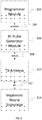
- FIG. 1 depicts a high-level diagram of an example of a wireless stimulation system.
- the wireless stimulation system may include four major components, namely, a programmer module 102 , a RF pulse generator module 106 , a transmit (TX) antenna 110 (for example, a patch antenna, slot antenna, or a dipole antenna), and an implanted wireless stimulator device 114 .
- the programmer module 102 may be a computer device, such as a smart phone, running a software application that supports a wireless connection 104 , such as Bluetooth®.
- the application can enable the user to view the system status and diagnostics, change various parameters, increase/decrease the desired stimulus amplitude of the electrode pulses, and adjust feedback sensitivity of the RF pulse generator module 106 , among other functions.
- the RF pulse generator module 106 may include communication electronics that support the wireless connection 104 , the stimulation circuitry, and the battery to power the generator electronics.
- the RF pulse generator module 106 includes the TX antenna embedded into its packaging form factor while, in other implementations, the TX antenna is connected to the RF pulse generator module 106 through a wired connection 108 or a wireless connection (not shown).
- the TX antenna 110 may be coupled directly to tissue to create an electric field that powers the implanted wireless stimulator device 114 .
- the TX antenna 110 communicates with the implanted wireless stimulator device 114 through an RF interface. For instance, the TX antenna 110 radiates an RF transmission signal that is modulated and encoded by the RF pulse generator module 110 .
- the implanted wireless stimulator device of module 114 contains one or more antennas, such as dipole antenna(s), to receive and transmit through RF interface 112 .
- the coupling mechanism between antenna 110 and the one or more antennas on the implanted wireless stimulation device of module 114 utilizes electrical radiative coupling and not inductive coupling. In other words, the coupling is through an electric field rather than a magnetic field.
- the TX antenna 110 can provide an input signal to the implanted wireless stimulator device 114 .
- This input signal contains energy and may contain information encoding stimulus waveforms to be applied at the electrodes of the implanted wireless stimulator device 114 .
- the power level of this input signal directly determines an applied amplitude (for example, power, current, or voltage) of the one or more electrical pulses created using the electrical energy contained in the input signal.
- an applied amplitude for example, power, current, or voltage
- Within the implanted wireless stimulator device 114 are components for demodulating the RF transmission signal, and electrodes to deliver the stimulation to surrounding neuronal tissue.
- the RF pulse generator module 106 can be implanted subcutaneously, or it can be worn external to the body. When external to the body, the RF generator module 106 can be incorporated into a belt or harness design to allow for electric radiative coupling through the skin and underlying tissue to transfer power and/or control parameters to the implanted wireless stimulator device 114 . In either event, receiver circuit(s) internal to the wireless stimulator device 114 (or cylindrical wireless implantable stimulator device 1400 shown in FIGS. 14A and 14B, helical wireless implantable stimulator device 1900 shown in FIGS. 19A to 19C) can capture the energy radiated by the TX antenna 110 and convert this energy to an electrical waveform. The receiver circuit(s) may further modify the waveform to create an electrical pulse suitable for the stimulation of neural tissue.
- the RF pulse generator module 106 can remotely control the stimulus parameters (that is, the parameters of the electrical pulses applied to the neural tissue) and monitor feedback from the wireless stimulator device 114 based on RF signals received from the implanted wireless stimulator device 114 .
- a feedback detection algorithm implemented by the RF pulse generator module 106 can monitor data sent wirelessly from the implanted wireless stimulator device 114 , including information about the energy that the implanted wireless stimulator device 114 is receiving from the RF pulse generator and information about the stimulus waveform being delivered to the electrode pads.
- the system can be tuned to provide the optimal amount of excitation or inhibition to the nerve fibers by electrical stimulation.
- a closed loop feedback control method can be used in which the output signals from the implanted wireless stimulator device 114 are monitored and used to determine the appropriate level of neural stimulation current for maintaining effective neuronal activation, or, in some cases, the patient can manually adjust the output signals in an open loop control method.
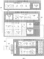
- FIG. 2 depicts a detailed diagram of an example of the wireless stimulation system.
- the programming module 102 may comprise user input system 202 and communication subsystem 208 .
- the user input system 221 may allow various parameter settings to be adjusted (in some cases, in an open loop fashion) by the user in the form of instruction sets.
- the communication subsystem 208 may transmit these instruction sets (and other information) via the wireless connection 104 , such as Bluetooth or Wi-Fi, to the RF pulse generator module 106 , as well as receive data from module 106 .
- the programmer module 102 which can be utilized for multiple users, such as a patient's control unit or clinician's programmer unit, can be used to send stimulation parameters to the RF pulse generator module 106 .
- the stimulation parameters that can be controlled may include pulse amplitude, pulse frequency, and pulse width in the ranges shown in Table 1 .
- the term pulse refers to the phase of the waveform that directly produces stimulation of the tissue; the parameters of the charge-balancing phase (described below) can similarly be controlled.
- the patient and/or the clinician can also optionally control overall duration and pattern of treatment.
- the RF pulse generator module 106 may be initially programmed to meet the specific parameter settings for each individual patient during the initial implantation procedure. Because medical conditions or the body itself can change over time, the ability to re-adjust the parameter settings may be beneficial to ensure ongoing efficacy of the neural modulation therapy.
- the programmer module 102 may be functionally a smart device and associated application.
- the smart device hardware may include a CPU 206 and be used as a vehicle to handle touchscreen input on a graphical user interface (GUI) 204 , for processing and storing data.
- GUI graphical user interface
- the RF pulse generator module 106 may be connected via wired connection 108 to an external TX antenna 110 .
- both the antenna and the RF pulse generator are located subcutaneously (not shown).
- the signals sent by RF pulse generator module 106 to the implanted wireless stimulator device 114 may include both power and parameter-setting attributes in regards to stimulus waveform, amplitude, pulse width, and frequency.
- the RF pulse generator module 106 can also function as a wireless receiving unit that receives feedback signals from the implanted wireless stimulator device 114 .
- the RF pulse generator module 106 may contain microelectronics or other circuitry to handle the generation of the signals transmitted to the device 114 as well as handle feedback signals, such as those from the stimulator device 114 .
- the RF pulse generator module 106 may comprise controller subsystem 214 , high-frequency oscillator 218 , RF amplifier 216 , a RF switch, and a feedback subsystem 212 .
- the controller subsystem 214 may include a CPU 230 to handle data processing, a memory subsystem 228 such as a local memory, communication subsystem 234 to communicate with programmer module 102 (including receiving stimulation parameters from programmer module), pulse generator circuitry 236 , and digital/analog (D/A) converters 232 .
- a CPU 230 to handle data processing
- a memory subsystem 228 such as a local memory
- communication subsystem 234 to communicate with programmer module 102 (including receiving stimulation parameters from programmer module)
- pulse generator circuitry 236 including receiving stimulation parameters from programmer module
- D/A converters 232 digital/analog
- the controller subsystem 214 may be used by the patient and/or the clinician to control the stimulation parameter settings (for example, by controlling the parameters of the signal sent from RF pulse generator module 106 to the stimulator device 114 ). These parameter settings can affect, for example, the power, current level, or shape of the one or more electrical pulses.
- the programming of the stimulation parameters can be performed using the programming module 102 , as described above, to set the repetition rate, pulse width, amplitude, and waveform that will be transmitted by RF energy to the receiving (RX) antenna 238 , typically a dipole antenna (although other types may be used), in the implanted wireless stimulation device 214 .
- the clinician may have the option of locking and/or hiding certain settings within the programmer interface, thus limiting the patient's ability to view or adjust certain parameters because adjustment of certain parameters may require detailed medical knowledge of neurophysiology, neuroanatomy, protocols for neural modulation, and safety limits of electrical stimulation.
- the controller subsystem 214 may store received parameter settings in the local memory subsystem 228 , until the parameter settings are modified by new input data received from the programming module 102 .
- the CPU 206 may use the parameters stored in the local memory to control the pulse generator circuitry 236 to generate a stimulus waveform that is modulated by a high frequency oscillator 218 in the range from 300 MHz to 8 GHz (preferably between about 700 MHz and 5.8 GHz and more preferably between about 800 MHz and 1.3 GHz).
- the resulting RF signal may then be amplified by RF amplifier 226 and then sent through an RF switch 223 to the TX antenna 110 to reach through depths of tissue to the RX antenna 238 .
- the RF signal sent by TX antenna 110 may simply be a power transmission signal used by the wireless stimulation device module 114 to generate electric pulses.
- a telemetry signal may also be transmitted to the wireless stimulator device 114 to send instructions about the various operations of the wireless stimulator device 114 .
- the telemetry signal may be sent by the modulation of the carrier signal (through the skin if external, or through other body tissues if the pulse generator module 106 is implanted subcutaneously).
- the telemetry signal is used to modulate the carrier signal (a high frequency signal) that is coupled onto the implanted antenna(s) 238 and does not interfere with the input received on the same stimulator device to power the device.
- the telemetry signal and powering signal are combined into one signal, where the RF telemetry signal is used to modulate the RF powering signal, and thus the wireless stimulation device is powered directly by the received telemetry signal; separate subsystems in the wireless stimulation device harness the power contained in the signal and interpret the data content of the signal.
- the RF switch 223 may be a multipurpose device such as a dual directional coupler, which passes the relatively high amplitude, extremely short duration RF pulse to the TX antenna 110 with minimal insertion loss while simultaneously providing two low-level outputs to feedback subsystem 212 ; one output delivers a forward power signal to the feedback subsystem 212 , where the forward power signal is an attenuated version of the RF pulse sent to the TX antenna 110 , and the other output delivers a reverse power signal to a different port of the feedback subsystem 212 , where reverse power is an attenuated version of the reflected RF energy from the TX Antenna 110 .
- a multipurpose device such as a dual directional coupler, which passes the relatively high amplitude, extremely short duration RF pulse to the TX antenna 110 with minimal insertion loss while simultaneously providing two low-level outputs to feedback subsystem 212 ; one output delivers a forward power signal to the feedback subsystem 212 , where the forward power signal is an attenuated version of the RF
- the RF switch 223 is set to send the forward power signal to feedback subsystem.
- the RF switch 223 can change to a receiving mode in which the reflected RF energy and/or RF signals from the wireless stimulator device 114 are received to be analyzed in the feedback subsystem 212 .
- the feedback subsystem 212 of the RF pulse generator module 106 may include reception circuitry to receive and extract telemetry or other feedback signals from the wireless stimulator device 114 and/or reflected RF energy from the signal sent by TX antenna 110 .
- the feedback subsystem may include an amplifier 226 , a filter 224 , a demodulator 222 , and an A/D converter 220 .
- the feedback subsystem 212 receives the forward power signal and converts this high-frequency AC signal to a DC level that can be sampled and sent to the controller subsystem 214 . In this way the characteristics of the generated RF pulse can be compared to a reference signal within the controller subsystem 214 . If a disparity (error) exists in any parameter, the controller subsystem 214 can adjust the output to the RF pulse generator 106 . The nature of the adjustment can be, for example, proportional to the computed error.
- the controller subsystem 214 can incorporate additional inputs and limits on its adjustment scheme such as the signal amplitude of the reverse power and any predetermined maximum or minimum values for various pulse parameters.
- the reverse power signal can be used to detect fault conditions in the RF-power delivery system.
- TX antenna 110 has perfectly matched impedance to the tissue that it contacts, the electromagnetic waves generated from the RF pulse generator 106 pass unimpeded from the TX antenna 110 into the body tissue.
- a large degree of variability may exist in the body types of users, types of clothing worn, and positioning of the antenna 110 relative to the body surface.
- the impedance of the antenna 110 depends on the relative permittivity of the underlying tissue and any intervening materials, and also depends on the overall separation distance of the antenna from the skin, in any given application there can be an impedance mismatch at the interface of the TX antenna 110 with the body surface. When such a mismatch occurs, the electromagnetic waves sent from the RF pulse generator 106 are partially reflected at this interface, and this reflected energy propagates backward through the antenna feed.
- the dual directional coupler RF switch 223 may prevent the reflected RF energy propagating back into the amplifier 226 , and may attenuate this reflected RF signal and send the attenuated signal as the reverse power signal to the feedback subsystem 212 .
- the feedback subsystem 212 can convert this high-frequency AC signal to a DC level that can be sampled and sent to the controller subsystem 214 .
- the controller subsystem 214 can then calculate the ratio of the amplitude of the reverse power signal to the amplitude of the forward power signal. The ratio of the amplitude of reverse power signal to the amplitude level of forward power may indicate severity of the impedance mismatch.
- the controller subsystem 214 can measure the reflected-power ratio in real time, and according to preset thresholds for this measurement, the controller subsystem 214 can modify the level of RF power generated by the RF pulse generator 106 .
- the course of action can be for the controller subsystem 214 to increase the amplitude of RF power sent to the TX antenna 110 , as would be needed to compensate for slightly non-optimum but acceptable TX antenna coupling to the body.
- the course of action can be to prevent operation of the RF pulse generator 106 and set a fault code to indicate that the TX antenna 110 has little or no coupling with the body.
- This type of reflected-power fault condition can also be generated by a poor or broken connection to the TX antenna. In either case, it may be desirable to stop RF transmission when the reflected-power ratio is above a defined threshold, because internally reflected power can lead to unwanted heating of internal components, and this fault condition means the system cannot deliver sufficient power to the implanted wireless stimulation device and thus cannot deliver therapy to the user.
- the controller 242 of the wireless stimulator device 114 may transmit informational signals, such as a telemetry signal, through the antenna 238 to communicate with the RF pulse generator module 106 during its receive cycle.
- the telemetry signal from the wireless stimulator device 114 may be coupled to the modulated signal on the dipole antenna(s) 238 , during the on and off state of the transistor circuit to enable or disable a waveform that produces the corresponding RF bursts necessary to transmit to the external (or remotely implanted) pulse generator module 106 .
- the antenna(s) 238 may be connected to electrodes 254 in contact with tissue to provide a return path for the transmitted signal.
- An A/D (not shown) converter can be used to transfer stored data to a serialized pattern that can be transmitted on the pulse-modulated signal from the internal antenna(s) 238 of the wireless stimulator device 114 .
- a telemetry signal from the implanted wireless stimulator device 114 may include stimulus parameters such as the power or the amplitude of the current that is delivered to the tissue from the electrodes.
- the feedback signal can be transmitted to the RF pulse generator module 116 to indicate the strength of the stimulus at the nerve bundle by means of coupling the signal to the implanted RX antenna 238 , which radiates the telemetry signal to the external (or remotely implanted) RF pulse generator module 106 .
- the feedback signal can include either or both an analog and digital telemetry pulse modulated carrier signal. Data such as stimulation pulse parameters and measured characteristics of stimulator performance can be stored in an internal memory device within the implanted stimulator device 114 , and sent on the telemetry signal.
- the frequency of the carrier signal may be in the range of at 300 MHz to 8 GHz (preferably between about 700 MHz and 5.8 GHz and more preferably between about 800 MHz and 1.3 GHz).
- the telemetry signal can be down modulated using demodulator 222 and digitized by being processed through an analog to digital (A/D) converter 220 .
- the digital telemetry signal may then be routed to a CPU 230 with embedded code, with the option to reprogram, to translate the signal into a corresponding current measurement in the tissue based on the amplitude of the received signal.
- the CPU 230 of the controller subsystem 214 can compare the reported stimulus parameters to those held in local memory 228 to verify the wireless stimulator device 114 delivered the specified stimuli to tissue.
- the power level from the RF pulse generator module 106 can be increased so that the implanted wireless stimulator device 114 will have more available power for stimulation.
- the implanted wireless stimulator device 114 can generate telemetry data in real time, for example, at a rate of 8 Kbits per second. All feedback data received from the implanted stimulator device 114 can be logged against time and sampled to be stored for retrieval to a remote monitoring system accessible by the health care professional for trending and statistical correlations.
- the sequence of remotely programmable RF signals received by the internal antenna(s) 238 may be conditioned into waveforms that are controlled within the implantable wireless stimulator device 114 by the control subsystem 242 and routed to the appropriate electrodes 254 that are placed in proximity to the tissue to be stimulated.
- the RF signal transmitted from the RF pulse generator module 106 may be received by RX antenna 238 and processed by circuitry, such as waveform conditioning circuitry 240 , within the implanted wireless stimulator device 114 to be converted into electrical pulses applied to the electrodes 254 through electrode interface 252 .
- the implanted wireless stimulator device 114 contains between two to sixteen electrodes 254 .
- the waveform conditioning circuitry 240 may include a rectifier 244 , which rectifies the signal received by the RX antenna 238 .
- the rectified signal may be fed to the controller 242 for receiving encoded instructions from the RF pulse generator module 106 .
- the rectifier signal may also be fed to a charge balance component 246 that is configured to create one or more electrical pulses based such that the one or more electrical pulses result in a substantially zero net charge at the one or more electrodes (that is, the pulses are charge balanced).
- the charge-balanced pulses are passed through the current limiter 248 to the electrode interface 252 , which applies the pulses to the electrodes 254 as appropriate.
- the current limiter 248 insures the current level of the pulses applied to the electrodes 254 is not above a threshold current level.
- an amplitude (for example, current level, voltage level, or power level) of the received RF pulse directly determines the amplitude of the stimulus.
- it is the charge per phase that should be limited for safety where the charge delivered by a stimulus phase is the integral of the current).
- the limiter 248 acts as a charge limiter that limits a characteristic (for example, current or duration) of the electrical pulses so that the charge per phase remains below a threshold level (typically, a safe-charge limit).
- the current limiter 248 can automatically limit or "clip" the stimulus phase to maintain the total charge of the phase within the safety limit.
- the current limiter 248 may be a passive current limiting component that cuts the signal to the electrodes 254 once the safe current limit (the threshold current level) is reached. Alternatively, or additionally, the current limiter 248 may communicate with the electrode interface 252 to turn off all electrodes 254 to prevent tissue damaging current levels.
- a clipping event may trigger a current limiter feedback control mode.
- the action of clipping may cause the controller to send a threshold power data signal to the pulse generator 106 .
- the feedback subsystem 212 detects the threshold power signal and demodulates the signal into data that is communicated to the controller subsystem 214 .
- the controller subsystem 214 algorithms may act on this current-limiting condition by specifically reducing the RF power generated by the RF pulse generator, or cutting the power completely. In this way, the pulse generator 106 can reduce the RF power delivered to the body if the implanted wireless stimulator device 114 reports it is receiving excess RF power.
- the controller 250 of the stimulator 205 may communicate with the electrode interface 252 to control various aspects of the electrode setup and pulses applied to the electrodes 254.
- the electrode interface 252 may act as a multiplex and control the polarity and switching of each of the electrodes 254 .
- the wireless stimulator 106 has multiple electrodes 254 in contact with tissue, and for a given stimulus the RF pulse generator module 106 can arbitrarily assign one or more electrodes to 1 ) act as a stimulating electrode, 2 ) act as a return electrode, or 3 ) be inactive by communication of assignment sent wirelessly with the parameter instructions, which the controller 250 uses to set electrode interface 252 as appropriate. It may be physiologically advantageous to assign, for example, one or two electrodes as stimulating electrodes and to assign all remaining electrodes as return electrodes.
- the controller 250 may control the electrode interface 252 to divide the current arbitrarily (or according to instructions from pulse generator module 106 ) among the designated stimulating electrodes.
- This control over electrode assignment and current control can be advantageous because in practice the electrodes 254 may be spatially distributed along various neural structures, and through strategic selection of the stimulating electrode location and the proportion of current specified for each location, the aggregate current distribution in tissue can be modified to selectively activate specific neural targets. This strategy of current steering can improve the therapeutic effect for the patient.
- the time course of stimuli may be arbitrarily manipulated.
- a given stimulus waveform may be initiated at a time T_start and terminated at a time T_final, and this time course may be synchronized across all stimulating and return electrodes; further, the frequency of repetition of this stimulus cycle may be synchronous for all the electrodes.
- controller 250 on its own or in response to instructions from pulse generator 106 , can control electrode interface 252 to designate one or more subsets of electrodes to deliver stimulus waveforms with non-synchronous start and stop times, and the frequency of repetition of each stimulus cycle can be arbitrarily and independently specified.
- a stimulator having eight electrodes may be configured to have a subset of five electrodes, called set A, and a subset of three electrodes, called set B.
- Set A might be configured to use two of its electrodes as stimulating electrodes, with the remainder being return electrodes.
- Set B might be configured to have just one stimulating electrode.
- the controller 250 could then specify that set A deliver a stimulus phase with 3 mA current for a duration of 200 us followed by a 400 us charge-balancing phase. This stimulus cycle could be specified to repeat at a rate of 60 cycles per second. Then, for set B, the controller 250 could specify a stimulus phase with 1 mA current for duration of 500 us followed by a 800 us charge-balancing phase.
- the repetition rate for the set-B stimulus cycle can be set independently of set A, say for example it could be specified at 25 cycles per second. Or, if the controller 250 was configured to match the repetition rate for set B to that of set A, for such a case the controller 250 can specify the relative start times of the stimulus cycles to be coincident in time or to be arbitrarily offset from one another by some delay interval.
- the controller 250 can arbitrarily shape the stimulus waveform amplitude, and may do so in response to instructions from pulse generator 106 .
- the stimulus phase may be delivered by a constant-current source or a constant-voltage source, and this type of control may generate characteristic waveforms that are static, e.g. a constant-current source generates a characteristic rectangular pulse in which the current waveform has a very steep rise, a constant amplitude for the duration of the stimulus, and then a very steep return to baseline.
- the controller 250 can increase or decrease the level of current at any time during the stimulus phase and/or during the charge-balancing phase.
- the controller 250 can deliver arbitrarily shaped stimulus waveforms such as a triangular pulse, sinusoidal pulse, or Gaussian pulse for example.
- the charge-balancing phase can be arbitrarily amplitude-shaped, and similarly a leading anodic pulse (prior to the stimulus phase) may also be amplitude-shaped.
- the wireless stimulator device 114 may include a charge-balancing component 246 .
- pulses should be charge balanced by having the amount of cathodic current should equal the amount of anodic current, which is typically called biphasic stimulation.
- Charge density is the amount of current times the duration it is applied, and is typically expressed in the units uC/cm 2 .
- no net charge should appear at the electrode-electrolyte interface, and it is generally acceptable to have a charge density less than 30 uC/cm 2 .
- Biphasic stimulating current pulses ensure that no net charge appears at the electrode after each stimulation cycle and the electrochemical processes are balanced to prevent net dc currents.
- the wireless stimulator device 114 may be designed to ensure that the resulting stimulus waveform has a net zero charge. Charge balanced stimuli are thought to have minimal damaging effects on tissue by reducing or eliminating electrochemical reaction products created at the electrode-tissue interface.
- a stimulus pulse may have a negative- voltage or current, called the cathodic phase of the waveform.
- Stimulating electrodes may have both cathodic and anodic phases at different times during the stimulus cycle.
- An electrode that delivers a negative current with sufficient amplitude to stimulate adjacent neural tissue is called a "stimulating electrode.”
- the stimulating electrode acts as a current sink.
- One or more additional electrodes act as a current source and these electrodes are called “return electrodes.” Return electrodes are placed elsewhere in the tissue at some distance from the stimulating electrodes.
- the return electrode When a typical negative stimulus phase is delivered to tissue at the stimulating electrode, the return electrode has a positive stimulus phase.
- the polarities of each electrode are reversed.
- the charge balance component 246 uses a blocking capacitor(s) placed electrically in series with the stimulating electrodes and body tissue, between the point of stimulus generation within the stimulator circuitry and the point of stimulus delivery to tissue.
- a resistor-capacitor (RC) network may be formed.
- one charge-balance capacitor(s) may be used for each electrode or a centralized capacitor(s) may be used within the stimulator circuitry prior to the point of electrode selection.
- the RC network can block direct current (DC), however it can also prevent low-frequency alternating current (AC) from passing to the tissue.
- the frequency below which the series RC network essentially blocks signals is commonly referred to as the cutoff frequency, and in one embodiment the design of the stimulator system may ensure the cutoff frequency is not above the fundamental frequency of the stimulus waveform.
- the wireless stimulator may have a charge-balance capacitor with a value chosen according to the measured series resistance of the electrodes and the tissue environment in which the stimulator is implanted. By selecting a specific capacitance value the cutoff frequency of the RC network in this embodiment is at or below the fundamental frequency of the stimulus pulse.
- the cutoff frequency may be chosen to be at or above the fundamental frequency of the stimulus, and in this scenario the stimulus waveform created prior to the charge-balance capacitor, called the drive waveform, may be designed to be non-stationary, where the envelope of the drive waveform is varied during the duration of the drive pulse.
- the initial amplitude of the drive waveform is set at an initial amplitude Vi, and the amplitude is increased during the duration of the pulse until it reaches a final value k ⁇ Vi.
- the shape of the stimulus waveform passed through the charge-balance capacitor is also modified. The shape of the stimulus waveform may be modified in this fashion to create a physiologically advantageous stimulus.
- the wireless stimulator device 114 may create a drive-waveform envelope that follows the envelope of the RF pulse received by the receiving dipole antenna(s) 238 .
- the RF pulse generator module 106 can directly control the envelope of the drive waveform within the wireless stimulator device 114 , and thus no energy storage may be required inside the stimulator itself.
- the stimulator circuitry may modify the envelope of the drive waveform or may pass it directly to the charge-balance capacitor and/or electrode-selection stage.
- the implanted wireless stimulator device 114 may deliver a single-phase drive waveform to the charge balance capacitor or it may deliver multiphase drive waveforms.
- a single-phase drive waveform for example, a negative-going rectangular pulse
- this pulse comprises the physiological stimulus phase
- the charge-balance capacitor is polarized (charged) during this phase.
- the charge balancing function is performed solely by the passive discharge of the charge-balance capacitor, where is dissipates its charge through the tissue in an opposite polarity relative to the preceding stimulus.
- a resistor within the stimulator facilitates the discharge of the charge-balance capacitor.
- the capacitor may allow virtually complete discharge prior to the onset of the subsequent stimulus pulse.
- the wireless stimulator may perform internal switching to pass negative-going or positive-going pulses (phases) to the charge-balance capacitor.
- phases positive-going pulses
- These pulses may be delivered in any sequence and with varying amplitudes and waveform shapes to achieve a desired physiological effect.
- the stimulus phase may be followed by an actively driven charge-balancing phase, and/or the stimulus phase may be preceded by an opposite phase.
- Preceding the stimulus with an opposite-polarity phase for example, can have the advantage of reducing the amplitude of the stimulus phase required to excite tissue.
- the amplitude and timing of stimulus and charge-balancing phases is controlled by the amplitude and timing of RF pulses from the RF pulse generator module 106 , and in others this control may be administered internally by circuitry onboard the wireless stimulator device 114 , such as controller 250 . In the case of onboard control, the amplitude and timing may be specified or modified by data commands delivered from the pulse generator module 106 .
- the transmit antenna 110 can be placed in close proximity to the receiving antenna 238.
- the transmit antenna 110 may be worn by the patient.
- the transmit antenna 110 may be placed further away from the patient (and the implanted passive neural stimulator that houses receiving antenna 238). In the former case, less energy may be emitted from the remote antenna to wirelessly provide power and stimulation parameter settings to the passive neural stimulator.
- the patient may remain stationary or asleep. During sleep, the patient may not desire to wear a transmitting antenna 110 that is coupled to a controller module (such as controller subsystem 214) through a cable.
- An antenna assembly may be used to remotely provide power and stimulation parameter settings to the passive neural stimulator.
- the antenna assembly in this example may be more than 10 centimeters away from the passive neural stimulator implanted inside a patient. If the patient can move around a room; the entire room may need to be illuminated with the microwave energy field. In this scenario, an array of antennas, or a broad beam-width antenna, may be used. Some implementations may incorporate a steerable (e.g., mechanically, electrically) arrangement of antennas that include a receiving antenna location tracking system. These implementations may further apply motion control of the transmitting antenna 110 to adjust angle or orientation of illumination of an antenna to point in the direction of the receiving antenna. The output power is adjusted as needed depending on the distance between the transmitting and receiving antennas and the directivity of the transmitting antenna.
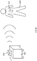
- FIGS. 3A-3C show examples of operations of a RF stimulation system. These examples may incorporate a single remote transmitting antenna or an array of transmitting antennas. In some instances, the array may be steerable to focus on a particular location. In other instances, the transmitting antenna(s) may be fixed.
- a patient 304 implanted with a neural stimulator device 114 is resting in bed 306 while receiving therapy from a transmitting antenna system 302 (e.g., transmitting antenna 110 and controller subsystem 214 ).
- the transmitting antenna system 302 is placed elsewhere in the same room to transmit electromagnetic energy 308 including power and stimulation parameters to implanted neural stimulator device 114 .
- the remote transmitting antenna system 302 may be placed on a dresser 310 or a night-stand near the patient bed.
- the remote transmitting antenna 310 system may be battery or wall powered.
- the remote transmitting antenna system 310 may receive programming or therapeutic instructions manually via physical buttons (or other tactile user interface on controller subsystem 214 ) or by a wireless instruction protocol such as Bluetooth or RF (e.g., cellular, Wi-Fi, etc.) from a programming module (not shown).
- the patient 304 may control the remote transmitting antenna system 302 via the physical buttons or Bluetooth.
- FIG. 3B depicts a similar scenario of transmitting electromagnetic energy 308 to remotely provide power and stimulator parameters to an implanted neural stimulator device 114 while patient 304 is standing or walking around without a wearable antenna system.
- transmitting antenna system 302 e.g., transmitting antenna 110 and controller subsystem 214
- transmitting antenna system 302 is placed on arbitrary furniture 320 in the same room as the standing or walking patient.
- FIG. 3C depicts another similar scenario in which patient 304 with implanted neural stimulator device 114 is sitting away from transmitting antenna system 302 (e.g., transmitting antenna 110 and controller subsystem 214 ).
- patient 304 may sit in an office chair.
- electromagnetic energy 308 is transmitted from transmitting antenna system 302 to remotely provide power and stimulation parameters to an implanted neural stimulator device 114 .
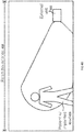
- FIG. 4A illustrates a top view of radiation volume 404 as transmitted from the remote transmitting antenna system 302 . More particularly, the range of the remote transmitting antenna system 302 is shown as generally conical and directional, extending in one direction from the remote transmitting antenna system 302 . Generally, the patient 406 may need to stay within the radiation volume to receive the desired stimulation therapy. The volume may interact with a standing or sitting patient (i.e., the remote transmitting antenna system may be configured to interact with an implanted antenna within a given distance and effective angle from the remote antenna).
- FIG. 4B illustrates a side and three-dimensional view of radiation volume 404 as generated by the remote transmitting antenna system 302 .
- the system radiation volume 404 can cover a patient 406 standing within the effective angles/distances to generate an effective electric field at the receiving antenna on implanted neural stimulator device 114 while the patient is standing.
- wireless transmission of power and stimulation parameters generally operate by line of sight.
- transmitting antenna system 302 generally emits electromagnetic radiation through free space and then into the human body and implanted neural stimulator device 114.
- Blocking objects such as those with lossy conducting material (e.g., low permittivity) or a material that reflects RF, such as metals, may negatively impact wireless transmission.
- the position of transmitting antenna system 302 may be adjusted such that a radiating surface of transmitting antenna system 302 is no less than one foot from the implanted neural stimulator device. In this configuration, transmitting antenna system 302 may not be a wearable gear for the patient. The position of transmitting antenna system 302 may also be adjusted such that the radiating surface of transmitting antenna system 302 is no more than six foot from the implanted neural stimulator device in order for the implantable neural stimulator device to receive sufficient operating energy wirelessly from the transmitting antenna system 302.
- Transmitting antenna system 302 may radiate polarized electromagnetic energy and an orientation of a transmitting antenna on the transmitting antenna system 302 may be adjusted so that the transmitting antenna is better aligned with the receiving antenna on the implantable neural stimulator device. When the alignment is improved through re-orientation, electromagnetic energy received at the receiving antenna can be increased as well.
- remote transmitting antenna system 302 includes a rectangular aperture waveguide 506 surrounding the antenna having a radiating surface 504 and a feed port 502.
- Feed port 502 may include a cable connector 508 for coupling to a cable.
- Example connectors may include BNC (Bayonet Neill-Concelman) connector, or SMA (SubMiniature version A) connectors.
- the radiating surface 504 of the antenna is bowtie-shaped.
- this bowtie shape also includes two rod structures 504A and 504B connecting the two leaf structures.
- the bowtie-shaped radiating surface 504 has contacts 504C and 504D connecting wave guide 506.
- the bowtie antenna distributes electromagnetic field in wave guide 506 and induces wave guide mode of propagation polarized along, for example, a long axis of rod structures 504Aand 504B.
- the bowtie antenna may radiate over a wide bandwidth like a dipole.
- Surrounding the antenna with waveguide 506 improves directivity of the antenna.
- Scaling the antenna size can determine the bandwidth of the antenna.
- the antenna size may be scaled such that the antenna is parameterized to have a band from 500MHz to 4GHz. The scaling may be simplified to just the length, width, and height of the interior of the rectangular waveguide.
- Table 1 UWB Antenna example dimensions following parameterization Optimized UWB Antenna Dimension Value [units] Length of the Waveguide (Interior) 30 [cm] Width of the Waveguide (Interior) 15 [cm] Height of the Waveguide (Interior) 10.03 [cm]
- the waveguide dimensions may be scaled with the operating frequency of the bowtie-shaped antenna.
- each wave guide has a cut-off frequency beyond which the wave guide cannot support wave propagation.
- the wave guide needs to be large enough to support the propagation of the electromagnetic wave from the transmitting antenna. Yet, it is advantageous to have a compact transmitting antenna system for applications as depicted in FIGS 3A-3C .
- the bowtie antenna assembly as depicted herein may be smaller in size than horn antennas operating at the same frequency. In some instances, bowtie antenna assembly can be a factor of 2 to 3 smaller than a horn antenna operating at the same frequency.
- the directivity of the bowtie antenna assembly may also be controlled.
- the antenna may include a tapered dielectric transition from the mouth of the waveguide and over the radiating surface. The tapering may match the waveguide at the mouth so that the reflection back to the feed port 508 is reduced. The tapering may also focus the main beam of the bowtie antenna by spatially narrowing the beam width. For example, tapering in one spatial dimension can lead to narrowing of the beam width of the transmitted electromagnetic beam in the same dimension.
- CB-RAA cavity backed rectangular aperture antennas
- CB-RAA cavity backed rectangular aperture antennas
- CB-RAA can possess radiation characteristics for radiating over a wide bandwidth. Further, its radiation efficiency is very close to that from a circular aperture (81% vs. 83.6%), while the electric field lines of CB-RAA are parallel, thereby improving the cross-polarization performance when the transmission is off the bore sight of the transmitting antenna 110.
- the remote transmitting antenna 110 is advantageously a directional, efficient, and far reaching antenna, all while relatively simple and easy to manufacture.
- the cross-polarization and E-field orientation for the transmitting antenna 110 may allow for a range of positions for placing the antenna such that sufficient energy reaches the implanted antenna to power the same.
- the large bandwidth response associated with addition of the waveguide and focusing lens may allow fine-tuning of the transmitting antenna 110 to a particular frequency, thereby rendering antenna more capable to operate at various particular frequencies.
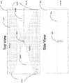
- FIGS. 6A-6C an example of an antenna assembly with a wave guide are shown.
- a side plate is removed to reveal the internal structure of the antenna assembly, which includes the transmitting antenna 110 with a bowtie-shaped radiating surface and a feed port coupled to a cable connector.
- FIG. 6C depicts an intact antenna assembly (with no sidewalls removed). The dimensions match the dimensions of the target antenna model (shown in Table 1) within a tolerance of ⁇ 0.5 mm.
- FIG. 7 illustrates the comparison of return loss over the frequency band of interest for the HFSS model (from the finite element solver) and the prototype of the antenna assembly of FIG. 6 .
- the return loss characterizes the amount of reflected energy from impedance mismatching of the antenna. More reflection loss indicates a more effective power transfer.
- both simulated and actually measured values for the return loss were generally less than or equal to -5 dB.
- the actually measured prototype values closely matched or improved upon the modeling results at frequencies between 500MHz and 1.25GHz.
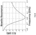
- FIG. 8 shows an example of simulated return loss characteristics of an antenna assembly designed with a resonance frequency of 915MHz. As shown, a reflection notch occurs at 915MHz as desired following the parameterizing of the bowtie antenna to 915MHz.
- FIGS. 9A-9B show examples of simulated electromagnetic radiation patterns from the antenna assembly of FIG. 8 . These patterns correspond to the total far field radiation pattern at resonance (915MHz) for the parameterized bowtie antenna.
- the pattern is calculated for the bowtie antenna and without a wave guide. In this arrangement, the bowtie antenna radiates uniformly around its axis of polarization.
- a rectangular waveguide can be placed around the bowtie antenna.
- FIG. 9B shows the improved directivity as demonstrated in the far field radiation pattern for the bowtie antenna at resonance (915 MHz) and with a rectangular aperture waveguide. As illustrated, the energy is concentrated in a lobe as directed by the aperture of the waveguide.
- the beam width can be reduced by 50% or more by the rectangular waveguide.
- the return loss, and in turn the impedance match may decrease due to frequency shaping caused by a cutoff frequency of the wave guide.
- a dielectric dome 1006 is mounted on the mouth of the waveguide aperture 1004 and over the radiating surface 1002.
- the dome 1004 acts as a focusing lens at the mouth of the antenna.
- the addition of the dielectric dome 1006 to fill the wave guide and over the mouth of the wave guide can provide several benefits to the design of the bowtie antenna, including, for example, lowering the return loss cutoff frequency of the rectangular wave guide without the dielectric filling to below 915MHz so that the size of the rectangular wave guide can be further reduced.
- the dielectric dome when tapered, can spatially narrow the energy transmitted so that the transmission becomes more focused. For example, the dielectric dome, tapered in one dimension, can cause the beam width of the radiated electromagnetic wave to be narrower in the same dimension.
- the dome may be of a simple half-cycle sinusoid or Gaussian shape, for example, along the Y direction (while the profile along the X-direction may remain constant).
- the antenna assembly may induce a wave guide mode of transmission pattern that is polarized along the X direction (along the direction of the long axis of rod structures 1002Aand 1002B).
- the shaped dielectric dome may fill the wave guide above and below the bowtie antenna.
- the shape or profile variation extends only from the mouth of the wave guide, as illustrated.
- the shape or profile variation--along the Y direction as illustrated in this case- may facilitate reducing the spread of the transmitted electromagnetic energy as it propagates forward.
- the height of dome refers to the height extending from the month of the wave guide to the summit of the dome. In some implementations, the height may vary from 0.5 in to 6 in, depending on the dielectric constant, which can vary from 1.5 to 9. For a 915MHz operation, the height of the dielectric dome was chosen at 3 inches.
- L denotes the length of the wave guide and scales in the range from 2.5 cm to 10 cm.
- Hbowtie refers to the height position of the Bowtie and may be fixed at L/2.
- "a” refers to the shorter lateral dimension of wave guide base, which can scale in the range from 3.75 cm to 7.5 cm, while “b” refers to the longer lateral dimension of the wave guide base, which may range from 7.5 cm to 15cm.
- Choosing a particular dielectric constant may reduce the size of the wave guide.
- the dielectric constant may also help release the electromagnetic wave from the metal wave guide, thereby serving as a buffer to reduce the reflection at the feed port.
- the feed port may be coupled to a 50 ohm coaxial cable via various connectors (e.g., BNC, SMA, etc.) as discussed above.
- FIGS. 11A-11B shows the simulated return loss and transmission characteristics of the antenna assembly of FIG. 10 .
- the return loss is plotted as a function of frequency, for a range of dome heights.
- the return loss shown is a relative return loss, as compared to a baseline return loss for two dipole antennas operating at 915MHz and separated at 1 in apart.
- the results from the parameterizations i.e., designing by adjusting system parameters
- the size trade-offs for the relatively small gains in reflection loss indicate only marginal gains above three inches. Thus, three inches may be deemed as the smallest height with an acceptable reflection loss, and thus the desirable dome height.
- FIG. 11B shows the simulated transmission loss versus frequency for a range of dome heights.
- Transmission loss is a characterization of the attenuation of the transmitted electromagnetic wave. Larger values (less negative values) correspond to a better transmission loss and a more efficient antenna. Gains in transmission loss are diminishing when the dome height is over three inches. Notably, the transmission loss may serve as a complimentary measure of the performance of the remote transmission antenna. Thus, little benefit may be derived from making the dome height larger than three inches.
- the dimensions can be judiciously determined.
- An example of dimensions for 915MHz are presented in Table 2.
- the reflection and transmission loss plots illustrate that the design is substantially improved for the purpose of this disclosure, but to further validate the results, the contours of the electric field interactions at the receiver and the far field radiation pattern can be examined.
- the waveguide dimensions shown below in Table 2 scale with the dimensions of the bowtie antenna (as shown above in Table 1).
- Table 2 Final remote antenna dimensions following parameterization Optimized Remote Antenna Dimension Value [units] Length of the Waveguide (Interior) 15.0 [cm] Width of the Waveguide (Interior) 7.6 [cm] Height of the Waveguide (Interior) 5.0 [cm]
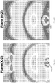
- FIG. 12 shows the perspective view of the simulated electromagnetic radiation pattern from the antenna assembly of FIG. 10 .
- FIG. 12 shows the far field radiation pattern at 915 MHz for the remote antenna design according to Table 2.
- the dielectrically loaded waveguide further improves directivity of the antenna to provide sufficient energy for delivery to the implanted neural stimulator device.
- the far field pattern shows that the additional dielectric loading further improves directivity that validates the previously found loss characterizations as well as the E-field propagation results.
- the pattern quantifies the spatial orientation variability of the antenna with respect to the implanted neural stimulator device. The results demonstrate that the implanted neural stimulator can be within 15° of the center axis of the remote transmitting antenna and still receive the majority of the transmitted energy.
- FIG. 13A-13B shows the X-Z and Y-Z plane views of the simulated electromagnetic radiation pattern of FIG. 12 .
- the receiver antenna 1304 is in the top portion of both planes.
- the contours show a forward traveling lobe of electromagnetic energy interacting with the receiver antenna 1304.
Claims (13)
- Ensemble antenne, comprenant :une antenne (110) qui comporte :une couche de signal métallique ayant une surface de rayonnement (504) ; etun orifice d'alimentation (502) ; etune guide d'ondes (506) entourant l'antenne et configuré de sorte à guider l'énergie électromagnétique transmise à partir de la surface de rayonnement dans une direction s'éloignant de l'antenne ; et un module de commande raccordé à l'orifice d'alimentation et configuré de sorte à commander à l'antenne de transmettre l'énergie électromagnétique à partir de la surface de rayonnement ;où l'antenne, le guide d'ondes et le module de commande sont configurés de telle sorte que, lorsque le module de commande (214) commande l'antenne, l'énergie électromagnétique transmise correspond à une caractéristique de réception d'un dispositif implantable et est suffisante pour que le dispositif implantable crée une ou plusieurs impulsions électriques d'une amplitude suffisante pour stimuler le tissu neural d'un patient, uniquement à l'aide de l'énergie électromagnétique reçue de l'antenne, lorsque le dispositif implantable est situé à au moins 10 centimètres de l'antenne ;où la surface de rayonnement peut être déplacée à partir d'une première orientation spatiale vers une seconde orientation spatiale de telle sorte que l'énergie électromagnétique polarisée reçue au niveau d'une antenne dipôle située sur le dispositif implantable à l'intérieur du patient est augmentée.
- Ensemble antenne selon la revendication 1, comprenant en outre :
une lentille diélectrique (1004) qui remplit le guide d'ondes et est en saillie vers l'extérieur depuis une ouverture du guide d'ondes pour former une saillie qui est mise en forme pour limiter dans l'espace l'énergie électromagnétique transmise dans la direction opposée à la surface de transmission. - Ensemble antenne selon la revendication 2, dans lequel la saillie a une forme conique.
- Ensemble antenne selon la revendication 3, dans lequel la saillie est conique pour avoir un profil gaussien ou sinusoïdal, et où l'ensemble antenne a une fréquence de coupure de la perte par réflexion associée au guide d'ondes et la lentille diélectrique est en outre configurée pour abaisser la fréquence de coupure de la perte par réflexion.
- Ensemble antenne selon la revendication 1, dans lequel l'antenne est opérationnelle à l'intérieur d'une bande de fréquences allant d'environ 500 MHz à environ 4 GHz.
- Ensemble antenne selon la revendication 1, dans lequel la surface de rayonnement est en forme de papillon et possède deux structures en forme de feuillet raccordées l'une à l'autre au niveau de l'orifice d'alimentation ainsi qu'au travers de deux structures en forme de tige sensiblement parallèles, où l'énergie électromagnétique transmise est polarisée le long d'un axe longitudinal des structures en forme de tige.
- Ensemble antenne selon la revendication 1, dans lequel le guide d'ondes est un guide d'ondes rectangulaire ayant quatre parois entourant une surface de rayonnement en forme de papillon.
- Ensemble antenne selon la revendication 7, dans lequel le guide d'ondes rectangulaire a une longueur intérieure d'environ 15 cm, une largeur intérieure d'environ 7,6 cm et une hauteur d'environ 5 cm, et où le guide d'ondes rectangulaire a une longueur intérieure d'au moins 10 cm, et le guide d'ondes a un rapport entre la longueur, la largeur et la hauteur intérieure d'environ 15 : 7,6 : 5.
- Système, comprenant :- un ensemble antenne selon la revendication 1, l'ensemble antenne étant configuré pour faire fonctionner sans fil le dispositif implantable ; et- le dispositif implantable pouvant fonctionner à partir d'un emplacement à l'intérieur d'un patient et qui est éloigné de plus de 10 centimètres de l'ensemble antenne,
où le dispositif implantable est configuré pour créer une ou plusieurs impulsions électriques de stimulation d'amplitude suffisante pour stimuler le tissu neural du patient en utilisant uniquement l'énergie électromagnétique reçue depuis l'ensemble antenne. - Système selon la revendication 9, dans lequel le guide d'ondes est un guide d'ondes rectangulaire ayant quatre parois qui entourent la surface de rayonnement ; où le guide d'ondes rectangulaire a une longueur intérieure d'environ 15 cm, une largeur intérieure d'environ 7,6 cm et une hauteur d'environ 5 cm ; et où le guide d'ondes rectangulaire a une longueur intérieure d'au moins 10 cm, et le guide d'ondes rectangulaire a un rapport entre la longueur, la largeur et la hauteur intérieure d'environ 15 : 7,6 : 5.
- Système selon la revendication 9 ou la revendication 10, comprenant en outre :
une lentille diélectrique qui remplit le guide d'ondes et qui est en saillie vers l'extérieur depuis une ouverture du guide d'ondes pour former une saillie qui est mise en forme pour limiter dans l'espace l'énergie électromagnétique transmise dans la direction opposée à la surface de transmission. - Système selon la revendication 11, dans lequel la saillie a une forme conique ; où la saillie est conique pour avoir un profil gaussien ou sinusoïdal ; et où l'antenne est opérationnelle à l'intérieur d'une bande de fréquences allant d'environ 500 MHz à environ 4 GHz.
- Système selon la revendication 9, dans lequel la surface de rayonnement est en forme de papillon et possède deux structures en forme de feuillet raccordées l'une à l'autre au niveau de l'orifice d'alimentation ainsi qu'au travers de deux structures en forme de tige sensiblement parallèles ; et où l'énergie électromagnétique transmise est polarisée le long d'un axe longitudinal des structures en forme de tige.
Applications Claiming Priority (2)
| Application Number | Priority Date | Filing Date | Title |
|---|---|---|---|
| US201461992150P | 2014-05-12 | 2014-05-12 | |
| PCT/US2015/030433 WO2015175572A1 (fr) | 2014-05-12 | 2015-05-12 | Système de puissance rf à distance ayant une antenne d'émission à profil bas |
Publications (3)
| Publication Number | Publication Date |
|---|---|
| EP3142743A1 EP3142743A1 (fr) | 2017-03-22 |
| EP3142743A4 EP3142743A4 (fr) | 2018-01-10 |
| EP3142743B1 true EP3142743B1 (fr) | 2020-07-29 |
Family
ID=54366910
Family Applications (1)
| Application Number | Title | Priority Date | Filing Date |
|---|---|---|---|
| EP15793285.6A Active EP3142743B1 (fr) | 2014-05-12 | 2015-05-12 | Système de puissance rf à distance ayant une antenne d'émission à profil bas |
Country Status (6)
| Country | Link |
|---|---|
| US (3) | US9409029B2 (fr) |
| EP (1) | EP3142743B1 (fr) |
| CN (2) | CN110665114B (fr) |
| AU (1) | AU2015259305B2 (fr) |
| IL (1) | IL248747B (fr) |
| WO (1) | WO2015175572A1 (fr) |
Families Citing this family (246)
| Publication number | Priority date | Publication date | Assignee | Title |
|---|---|---|---|---|
| EP3685880B1 (fr) | 2011-01-28 | 2021-03-24 | Stimwave Technologies Incorporated | Système de stimulateur neuronal |
| US9199089B2 (en) | 2011-01-28 | 2015-12-01 | Micron Devices Llc | Remote control of power or polarity selection for a neural stimulator |
| US9220897B2 (en) | 2011-04-04 | 2015-12-29 | Micron Devices Llc | Implantable lead |
| AU2012240239B2 (en) | 2011-04-04 | 2017-01-05 | Curonix Llc | Implantable lead |
| EP3912675A1 (fr) | 2011-08-12 | 2021-11-24 | Stimwave Technologies Incorporated | Stimulateur de champ à micro-ondes |
| TR201802844T4 (tr) | 2011-09-15 | 2018-03-21 | Andresen Chad | İmplant için röle modülü. |
| US20150018728A1 (en) | 2012-01-26 | 2015-01-15 | Bluewind Medical Ltd. | Wireless neurostimulators |
| US9812890B1 (en) | 2013-07-11 | 2017-11-07 | Energous Corporation | Portable wireless charging pad |
| US10075008B1 (en) | 2014-07-14 | 2018-09-11 | Energous Corporation | Systems and methods for manually adjusting when receiving electronic devices are scheduled to receive wirelessly delivered power from a wireless power transmitter in a wireless power network |
| US10312715B2 (en) | 2015-09-16 | 2019-06-04 | Energous Corporation | Systems and methods for wireless power charging |
| US9853692B1 (en) | 2014-05-23 | 2017-12-26 | Energous Corporation | Systems and methods for wireless power transmission |
| US9973021B2 (en) | 2012-07-06 | 2018-05-15 | Energous Corporation | Receivers for wireless power transmission |
| US9124125B2 (en) | 2013-05-10 | 2015-09-01 | Energous Corporation | Wireless power transmission with selective range |
| US9882427B2 (en) | 2013-05-10 | 2018-01-30 | Energous Corporation | Wireless power delivery using a base station to control operations of a plurality of wireless power transmitters |
| US9887739B2 (en) | 2012-07-06 | 2018-02-06 | Energous Corporation | Systems and methods for wireless power transmission by comparing voltage levels associated with power waves transmitted by antennas of a plurality of antennas of a transmitter to determine appropriate phase adjustments for the power waves |
| US10224982B1 (en) | 2013-07-11 | 2019-03-05 | Energous Corporation | Wireless power transmitters for transmitting wireless power and tracking whether wireless power receivers are within authorized locations |
| US9941754B2 (en) | 2012-07-06 | 2018-04-10 | Energous Corporation | Wireless power transmission with selective range |
| US10218227B2 (en) | 2014-05-07 | 2019-02-26 | Energous Corporation | Compact PIFA antenna |
| US9438045B1 (en) | 2013-05-10 | 2016-09-06 | Energous Corporation | Methods and systems for maximum power point transfer in receivers |
| US10063106B2 (en) | 2014-05-23 | 2018-08-28 | Energous Corporation | System and method for a self-system analysis in a wireless power transmission network |
| US9824815B2 (en) | 2013-05-10 | 2017-11-21 | Energous Corporation | Wireless charging and powering of healthcare gadgets and sensors |
| US9954374B1 (en) | 2014-05-23 | 2018-04-24 | Energous Corporation | System and method for self-system analysis for detecting a fault in a wireless power transmission Network |
| US10256657B2 (en) | 2015-12-24 | 2019-04-09 | Energous Corporation | Antenna having coaxial structure for near field wireless power charging |
| US10965164B2 (en) | 2012-07-06 | 2021-03-30 | Energous Corporation | Systems and methods of wirelessly delivering power to a receiver device |
| US10008889B2 (en) | 2014-08-21 | 2018-06-26 | Energous Corporation | Method for automatically testing the operational status of a wireless power receiver in a wireless power transmission system |
| US10063064B1 (en) | 2014-05-23 | 2018-08-28 | Energous Corporation | System and method for generating a power receiver identifier in a wireless power network |
| US9941747B2 (en) | 2014-07-14 | 2018-04-10 | Energous Corporation | System and method for manually selecting and deselecting devices to charge in a wireless power network |
| US9867062B1 (en) | 2014-07-21 | 2018-01-09 | Energous Corporation | System and methods for using a remote server to authorize a receiving device that has requested wireless power and to determine whether another receiving device should request wireless power in a wireless power transmission system |
| US10270261B2 (en) | 2015-09-16 | 2019-04-23 | Energous Corporation | Systems and methods of object detection in wireless power charging systems |
| US10263432B1 (en) | 2013-06-25 | 2019-04-16 | Energous Corporation | Multi-mode transmitter with an antenna array for delivering wireless power and providing Wi-Fi access |
| US9859757B1 (en) | 2013-07-25 | 2018-01-02 | Energous Corporation | Antenna tile arrangements in electronic device enclosures |
| US10193396B1 (en) | 2014-05-07 | 2019-01-29 | Energous Corporation | Cluster management of transmitters in a wireless power transmission system |
| US9847677B1 (en) | 2013-10-10 | 2017-12-19 | Energous Corporation | Wireless charging and powering of healthcare gadgets and sensors |
| US11502551B2 (en) | 2012-07-06 | 2022-11-15 | Energous Corporation | Wirelessly charging multiple wireless-power receivers using different subsets of an antenna array to focus energy at different locations |
| US10090886B1 (en) | 2014-07-14 | 2018-10-02 | Energous Corporation | System and method for enabling automatic charging schedules in a wireless power network to one or more devices |
| US9923386B1 (en) | 2012-07-06 | 2018-03-20 | Energous Corporation | Systems and methods for wireless power transmission by modifying a number of antenna elements used to transmit power waves to a receiver |
| US9876394B1 (en) | 2014-05-07 | 2018-01-23 | Energous Corporation | Boost-charger-boost system for enhanced power delivery |
| US10224758B2 (en) | 2013-05-10 | 2019-03-05 | Energous Corporation | Wireless powering of electronic devices with selective delivery range |
| US9991741B1 (en) | 2014-07-14 | 2018-06-05 | Energous Corporation | System for tracking and reporting status and usage information in a wireless power management system |
| US10103582B2 (en) | 2012-07-06 | 2018-10-16 | Energous Corporation | Transmitters for wireless power transmission |
| US9859756B2 (en) | 2012-07-06 | 2018-01-02 | Energous Corporation | Transmittersand methods for adjusting wireless power transmission based on information from receivers |
| US9843201B1 (en) | 2012-07-06 | 2017-12-12 | Energous Corporation | Wireless power transmitter that selects antenna sets for transmitting wireless power to a receiver based on location of the receiver, and methods of use thereof |
| US9899861B1 (en) | 2013-10-10 | 2018-02-20 | Energous Corporation | Wireless charging methods and systems for game controllers, based on pocket-forming |
| US9876379B1 (en) | 2013-07-11 | 2018-01-23 | Energous Corporation | Wireless charging and powering of electronic devices in a vehicle |
| US10230266B1 (en) | 2014-02-06 | 2019-03-12 | Energous Corporation | Wireless power receivers that communicate status data indicating wireless power transmission effectiveness with a transmitter using a built-in communications component of a mobile device, and methods of use thereof |
| US10090699B1 (en) | 2013-11-01 | 2018-10-02 | Energous Corporation | Wireless powered house |
| US10050462B1 (en) | 2013-08-06 | 2018-08-14 | Energous Corporation | Social power sharing for mobile devices based on pocket-forming |
| US10439448B2 (en) | 2014-08-21 | 2019-10-08 | Energous Corporation | Systems and methods for automatically testing the communication between wireless power transmitter and wireless power receiver |
| US9941707B1 (en) | 2013-07-19 | 2018-04-10 | Energous Corporation | Home base station for multiple room coverage with multiple transmitters |
| US10211682B2 (en) | 2014-05-07 | 2019-02-19 | Energous Corporation | Systems and methods for controlling operation of a transmitter of a wireless power network based on user instructions received from an authenticated computing device powered or charged by a receiver of the wireless power network |
| US9793758B2 (en) | 2014-05-23 | 2017-10-17 | Energous Corporation | Enhanced transmitter using frequency control for wireless power transmission |
| US9859797B1 (en) | 2014-05-07 | 2018-01-02 | Energous Corporation | Synchronous rectifier design for wireless power receiver |
| US9893768B2 (en) | 2012-07-06 | 2018-02-13 | Energous Corporation | Methodology for multiple pocket-forming |
| US10128699B2 (en) | 2014-07-14 | 2018-11-13 | Energous Corporation | Systems and methods of providing wireless power using receiver device sensor inputs |
| US10205239B1 (en) | 2014-05-07 | 2019-02-12 | Energous Corporation | Compact PIFA antenna |
| US9912199B2 (en) | 2012-07-06 | 2018-03-06 | Energous Corporation | Receivers for wireless power transmission |
| US10038337B1 (en) | 2013-09-16 | 2018-07-31 | Energous Corporation | Wireless power supply for rescue devices |
| US10199849B1 (en) | 2014-08-21 | 2019-02-05 | Energous Corporation | Method for automatically testing the operational status of a wireless power receiver in a wireless power transmission system |
| US9891669B2 (en) | 2014-08-21 | 2018-02-13 | Energous Corporation | Systems and methods for a configuration web service to provide configuration of a wireless power transmitter within a wireless power transmission system |
| US9887584B1 (en) | 2014-08-21 | 2018-02-06 | Energous Corporation | Systems and methods for a configuration web service to provide configuration of a wireless power transmitter within a wireless power transmission system |
| US10186913B2 (en) | 2012-07-06 | 2019-01-22 | Energous Corporation | System and methods for pocket-forming based on constructive and destructive interferences to power one or more wireless power receivers using a wireless power transmitter including a plurality of antennas |
| US9939864B1 (en) | 2014-08-21 | 2018-04-10 | Energous Corporation | System and method to control a wireless power transmission system by configuration of wireless power transmission control parameters |
| US9838083B2 (en) | 2014-07-21 | 2017-12-05 | Energous Corporation | Systems and methods for communication with remote management systems |
| US10148097B1 (en) | 2013-11-08 | 2018-12-04 | Energous Corporation | Systems and methods for using a predetermined number of communication channels of a wireless power transmitter to communicate with different wireless power receivers |
| US9876648B2 (en) | 2014-08-21 | 2018-01-23 | Energous Corporation | System and method to control a wireless power transmission system by configuration of wireless power transmission control parameters |
| US10141791B2 (en) | 2014-05-07 | 2018-11-27 | Energous Corporation | Systems and methods for controlling communications during wireless transmission of power using application programming interfaces |
| US10211674B1 (en) | 2013-06-12 | 2019-02-19 | Energous Corporation | Wireless charging using selected reflectors |
| US10199835B2 (en) | 2015-12-29 | 2019-02-05 | Energous Corporation | Radar motion detection using stepped frequency in wireless power transmission system |
| US10243414B1 (en) | 2014-05-07 | 2019-03-26 | Energous Corporation | Wearable device with wireless power and payload receiver |
| US9825674B1 (en) | 2014-05-23 | 2017-11-21 | Energous Corporation | Enhanced transmitter that selects configurations of antenna elements for performing wireless power transmission and receiving functions |
| US10992185B2 (en) | 2012-07-06 | 2021-04-27 | Energous Corporation | Systems and methods of using electromagnetic waves to wirelessly deliver power to game controllers |
| US20140008993A1 (en) | 2012-07-06 | 2014-01-09 | DvineWave Inc. | Methodology for pocket-forming |
| US10992187B2 (en) | 2012-07-06 | 2021-04-27 | Energous Corporation | System and methods of using electromagnetic waves to wirelessly deliver power to electronic devices |
| US9853458B1 (en) | 2014-05-07 | 2017-12-26 | Energous Corporation | Systems and methods for device and power receiver pairing |
| US9893554B2 (en) | 2014-07-14 | 2018-02-13 | Energous Corporation | System and method for providing health safety in a wireless power transmission system |
| US9843213B2 (en) | 2013-08-06 | 2017-12-12 | Energous Corporation | Social power sharing for mobile devices based on pocket-forming |
| US10124754B1 (en) | 2013-07-19 | 2018-11-13 | Energous Corporation | Wireless charging and powering of electronic sensors in a vehicle |
| US10206185B2 (en) | 2013-05-10 | 2019-02-12 | Energous Corporation | System and methods for wireless power transmission to an electronic device in accordance with user-defined restrictions |
| US9900057B2 (en) | 2012-07-06 | 2018-02-20 | Energous Corporation | Systems and methods for assigning groups of antenas of a wireless power transmitter to different wireless power receivers, and determining effective phases to use for wirelessly transmitting power using the assigned groups of antennas |
| US10128693B2 (en) | 2014-07-14 | 2018-11-13 | Energous Corporation | System and method for providing health safety in a wireless power transmission system |
| US9806564B2 (en) | 2014-05-07 | 2017-10-31 | Energous Corporation | Integrated rectifier and boost converter for wireless power transmission |
| US20150326070A1 (en) | 2014-05-07 | 2015-11-12 | Energous Corporation | Methods and Systems for Maximum Power Point Transfer in Receivers |
| US10063105B2 (en) | 2013-07-11 | 2018-08-28 | Energous Corporation | Proximity transmitters for wireless power charging systems |
| US10291066B1 (en) | 2014-05-07 | 2019-05-14 | Energous Corporation | Power transmission control systems and methods |
| US10211680B2 (en) | 2013-07-19 | 2019-02-19 | Energous Corporation | Method for 3 dimensional pocket-forming |
| US10141768B2 (en) | 2013-06-03 | 2018-11-27 | Energous Corporation | Systems and methods for maximizing wireless power transfer efficiency by instructing a user to change a receiver device's position |
| US9252628B2 (en) | 2013-05-10 | 2016-02-02 | Energous Corporation | Laptop computer as a transmitter for wireless charging |
| US9847679B2 (en) | 2014-05-07 | 2017-12-19 | Energous Corporation | System and method for controlling communication between wireless power transmitter managers |
| US9882430B1 (en) | 2014-05-07 | 2018-01-30 | Energous Corporation | Cluster management of transmitters in a wireless power transmission system |
| US9143000B2 (en) | 2012-07-06 | 2015-09-22 | Energous Corporation | Portable wireless charging pad |
| US9948135B2 (en) | 2015-09-22 | 2018-04-17 | Energous Corporation | Systems and methods for identifying sensitive objects in a wireless charging transmission field |
| US9368020B1 (en) | 2013-05-10 | 2016-06-14 | Energous Corporation | Off-premises alert system and method for wireless power receivers in a wireless power network |
| US9871398B1 (en) | 2013-07-01 | 2018-01-16 | Energous Corporation | Hybrid charging method for wireless power transmission based on pocket-forming |
| US10291055B1 (en) | 2014-12-29 | 2019-05-14 | Energous Corporation | Systems and methods for controlling far-field wireless power transmission based on battery power levels of a receiving device |
| US10223717B1 (en) | 2014-05-23 | 2019-03-05 | Energous Corporation | Systems and methods for payment-based authorization of wireless power transmission service |
| US9831718B2 (en) * | 2013-07-25 | 2017-11-28 | Energous Corporation | TV with integrated wireless power transmitter |
| US9893555B1 (en) | 2013-10-10 | 2018-02-13 | Energous Corporation | Wireless charging of tools using a toolbox transmitter |
| US9787103B1 (en) | 2013-08-06 | 2017-10-10 | Energous Corporation | Systems and methods for wirelessly delivering power to electronic devices that are unable to communicate with a transmitter |
| US9899873B2 (en) | 2014-05-23 | 2018-02-20 | Energous Corporation | System and method for generating a power receiver identifier in a wireless power network |
| US9966765B1 (en) | 2013-06-25 | 2018-05-08 | Energous Corporation | Multi-mode transmitter |
| US9906065B2 (en) | 2012-07-06 | 2018-02-27 | Energous Corporation | Systems and methods of transmitting power transmission waves based on signals received at first and second subsets of a transmitter's antenna array |
| US10381880B2 (en) | 2014-07-21 | 2019-08-13 | Energous Corporation | Integrated antenna structure arrays for wireless power transmission |
| WO2014087337A1 (fr) | 2012-12-06 | 2014-06-12 | Bluewind Medical Ltd. | Pose de neurostimulateurs implantables |
| EP2938393A1 (fr) | 2012-12-26 | 2015-11-04 | Micron Devices, LLC | Ensemble antenne portable |
| US9179336B2 (en) | 2013-02-19 | 2015-11-03 | Mimosa Networks, Inc. | WiFi management interface for microwave radio and reset to factory defaults |
| US9930592B2 (en) | 2013-02-19 | 2018-03-27 | Mimosa Networks, Inc. | Systems and methods for directing mobile device connectivity |
| US9130305B2 (en) | 2013-03-06 | 2015-09-08 | Mimosa Networks, Inc. | Waterproof apparatus for cables and cable interfaces |
| WO2014138292A1 (fr) | 2013-03-06 | 2014-09-12 | Mimosa Networks, Inc. | Enceinte pour radio, antenne à réflecteur parabolique, et blindages de lobe secondaire |
| US10742275B2 (en) | 2013-03-07 | 2020-08-11 | Mimosa Networks, Inc. | Quad-sector antenna using circular polarization |
| US9191081B2 (en) | 2013-03-08 | 2015-11-17 | Mimosa Networks, Inc. | System and method for dual-band backhaul radio |
| AU2014232252B2 (en) | 2013-03-15 | 2018-01-18 | Alfred E. Mann Foundation For Scientific Research | Current sensing multiple output current stimulators with fast turn on time |
| US9538382B2 (en) | 2013-05-10 | 2017-01-03 | Energous Corporation | System and method for smart registration of wireless power receivers in a wireless power network |
| US9537357B2 (en) | 2013-05-10 | 2017-01-03 | Energous Corporation | Wireless sound charging methods and systems for game controllers, based on pocket-forming |
| US9819230B2 (en) | 2014-05-07 | 2017-11-14 | Energous Corporation | Enhanced receiver for wireless power transmission |
| US9419443B2 (en) | 2013-05-10 | 2016-08-16 | Energous Corporation | Transducer sound arrangement for pocket-forming |
| US9866279B2 (en) | 2013-05-10 | 2018-01-09 | Energous Corporation | Systems and methods for selecting which power transmitter should deliver wireless power to a receiving device in a wireless power delivery network |
| CN105307719B (zh) | 2013-05-30 | 2018-05-29 | 格雷厄姆·H.·克雷西 | 局部神经刺激仪 |
| US9295103B2 (en) | 2013-05-30 | 2016-03-22 | Mimosa Networks, Inc. | Wireless access points providing hybrid 802.11 and scheduled priority access communications |
| US11229789B2 (en) | 2013-05-30 | 2022-01-25 | Neurostim Oab, Inc. | Neuro activator with controller |
| US10103552B1 (en) | 2013-06-03 | 2018-10-16 | Energous Corporation | Protocols for authenticated wireless power transmission |
| US10003211B1 (en) | 2013-06-17 | 2018-06-19 | Energous Corporation | Battery life of portable electronic devices |
| US10938110B2 (en) | 2013-06-28 | 2021-03-02 | Mimosa Networks, Inc. | Ellipticity reduction in circularly polarized array antennas |
| US10021523B2 (en) | 2013-07-11 | 2018-07-10 | Energous Corporation | Proximity transmitters for wireless power charging systems |
| US9979440B1 (en) | 2013-07-25 | 2018-05-22 | Energous Corporation | Antenna tile arrangements configured to operate as one functional unit |
| US9780596B2 (en) | 2013-07-29 | 2017-10-03 | Alfred E. Mann Foundation For Scientific Research | Microprocessor controlled class E driver |
| EP3046621B1 (fr) | 2013-09-16 | 2021-05-26 | The Board of Trustees of the Leland Stanford Junior University | Coupleur à éléments multiples permettant la production d'une énergie électromagnétique |
| US9001689B1 (en) | 2014-01-24 | 2015-04-07 | Mimosa Networks, Inc. | Channel optimization in half duplex communications systems |
| US10075017B2 (en) | 2014-02-06 | 2018-09-11 | Energous Corporation | External or internal wireless power receiver with spaced-apart antenna elements for charging or powering mobile devices using wirelessly delivered power |
| US9935482B1 (en) | 2014-02-06 | 2018-04-03 | Energous Corporation | Wireless power transmitters that transmit at determined times based on power availability and consumption at a receiving mobile device |
| US9780892B2 (en) | 2014-03-05 | 2017-10-03 | Mimosa Networks, Inc. | System and method for aligning a radio using an automated audio guide |
| US9998246B2 (en) | 2014-03-13 | 2018-06-12 | Mimosa Networks, Inc. | Simultaneous transmission on shared channel |
| US9966784B2 (en) | 2014-06-03 | 2018-05-08 | Energous Corporation | Systems and methods for extending battery life of portable electronic devices charged by sound |
| US10158257B2 (en) | 2014-05-01 | 2018-12-18 | Energous Corporation | System and methods for using sound waves to wirelessly deliver power to electronic devices |
| US9800172B1 (en) | 2014-05-07 | 2017-10-24 | Energous Corporation | Integrated rectifier and boost converter for boosting voltage received from wireless power transmission waves |
| US10153645B1 (en) | 2014-05-07 | 2018-12-11 | Energous Corporation | Systems and methods for designating a master power transmitter in a cluster of wireless power transmitters |
| US9973008B1 (en) | 2014-05-07 | 2018-05-15 | Energous Corporation | Wireless power receiver with boost converters directly coupled to a storage element |
| US10153653B1 (en) | 2014-05-07 | 2018-12-11 | Energous Corporation | Systems and methods for using application programming interfaces to control communications between a transmitter and a receiver |
| US10170917B1 (en) | 2014-05-07 | 2019-01-01 | Energous Corporation | Systems and methods for managing and controlling a wireless power network by establishing time intervals during which receivers communicate with a transmitter |
| CN110665114B (zh) | 2014-05-12 | 2022-12-06 | 斯蒂维科技公司 | 具有小尺寸发射天线的远程rf功率系统 |
| EP3753517B1 (fr) | 2014-05-18 | 2022-05-11 | Neuspera Medical Inc. | Coupleur de champ intermédiaire |
| US20160336813A1 (en) | 2015-05-15 | 2016-11-17 | NeuSpera Medical Inc. | Midfield coupler |
| US9876536B1 (en) | 2014-05-23 | 2018-01-23 | Energous Corporation | Systems and methods for assigning groups of antennas to transmit wireless power to different wireless power receivers |
| US10068703B1 (en) | 2014-07-21 | 2018-09-04 | Energous Corporation | Integrated miniature PIFA with artificial magnetic conductor metamaterials |
| US10116143B1 (en) | 2014-07-21 | 2018-10-30 | Energous Corporation | Integrated antenna arrays for wireless power transmission |
| US9871301B2 (en) | 2014-07-21 | 2018-01-16 | Energous Corporation | Integrated miniature PIFA with artificial magnetic conductor metamaterials |
| WO2016025915A1 (fr) | 2014-08-15 | 2016-02-18 | Axonics Modulation Technologies, Inc. | Programmateur clinicien électromyographique intégré destiné à être utilisé avec un neurostimulateur implantable |
| US9802038B2 (en) | 2014-08-15 | 2017-10-31 | Axonics Modulation Technologies, Inc. | Implantable lead affixation structure for nerve stimulation to alleviate bladder dysfunction and other indication |
| JP6878269B2 (ja) | 2014-08-15 | 2021-05-26 | アクソニクス モジュレーション テクノロジーズ インコーポレイテッド | 神経位置特定に基づく神経刺激電極構成のためのシステムおよび方法 |
| EP3180071B1 (fr) | 2014-08-15 | 2021-09-22 | Axonics, Inc. | Dispositif de générateur d'impulsion externe et systèmè associé pour une stimulation nerveuse d'essai |
| CA2958199C (fr) | 2014-08-15 | 2023-03-07 | Axonics Modulation Technologies, Inc. | Positionnement d'une derivation electromyographique et titrage de la stimulation dans un systeme de stimulation nerveuse pour le traitement de la vessie hyperactive |
| US9917477B1 (en) | 2014-08-21 | 2018-03-13 | Energous Corporation | Systems and methods for automatically testing the communication between power transmitter and wireless receiver |
| US9965009B1 (en) | 2014-08-21 | 2018-05-08 | Energous Corporation | Systems and methods for assigning a power receiver to individual power transmitters based on location of the power receiver |
| US10958332B2 (en) | 2014-09-08 | 2021-03-23 | Mimosa Networks, Inc. | Wi-Fi hotspot repeater |
| US10122415B2 (en) | 2014-12-27 | 2018-11-06 | Energous Corporation | Systems and methods for assigning a set of antennas of a wireless power transmitter to a wireless power receiver based on a location of the wireless power receiver |
| EP3242712B1 (fr) | 2015-01-09 | 2019-04-10 | Axonics Modulation Technologies, Inc. | Patient distant et procédés associés d'utilisation avec un système de stimulation nerveuse |
| CN107427683B (zh) | 2015-01-09 | 2019-06-21 | 艾克索尼克斯调制技术股份有限公司 | 用于可植入神经刺激器的改进天线和使用方法 |
| CN107427685B (zh) | 2015-01-09 | 2021-09-21 | 艾克索尼克斯股份有限公司 | 与神经刺激充电设备一起使用的附接设备及相关联方法 |
| US9893535B2 (en) | 2015-02-13 | 2018-02-13 | Energous Corporation | Systems and methods for determining optimal charging positions to maximize efficiency of power received from wirelessly delivered sound wave energy |
| US11077301B2 (en) | 2015-02-21 | 2021-08-03 | NeurostimOAB, Inc. | Topical nerve stimulator and sensor for bladder control |
| JP6946261B2 (ja) | 2015-07-10 | 2021-10-06 | アクソニクス インコーポレイテッド | Asicを用いない内部電子機器を有する埋め込み可能神経刺激装置および方法 |
| US9906275B2 (en) | 2015-09-15 | 2018-02-27 | Energous Corporation | Identifying receivers in a wireless charging transmission field |
| US10523033B2 (en) | 2015-09-15 | 2019-12-31 | Energous Corporation | Receiver devices configured to determine location within a transmission field |
| US10211685B2 (en) | 2015-09-16 | 2019-02-19 | Energous Corporation | Systems and methods for real or near real time wireless communications between a wireless power transmitter and a wireless power receiver |
| US10158259B1 (en) | 2015-09-16 | 2018-12-18 | Energous Corporation | Systems and methods for identifying receivers in a transmission field by transmitting exploratory power waves towards different segments of a transmission field |
| US10778041B2 (en) | 2015-09-16 | 2020-09-15 | Energous Corporation | Systems and methods for generating power waves in a wireless power transmission system |
| US10008875B1 (en) | 2015-09-16 | 2018-06-26 | Energous Corporation | Wireless power transmitter configured to transmit power waves to a predicted location of a moving wireless power receiver |
| US9893538B1 (en) | 2015-09-16 | 2018-02-13 | Energous Corporation | Systems and methods of object detection in wireless power charging systems |
| US10186893B2 (en) | 2015-09-16 | 2019-01-22 | Energous Corporation | Systems and methods for real time or near real time wireless communications between a wireless power transmitter and a wireless power receiver |
| US9871387B1 (en) | 2015-09-16 | 2018-01-16 | Energous Corporation | Systems and methods of object detection using one or more video cameras in wireless power charging systems |
| US10199850B2 (en) | 2015-09-16 | 2019-02-05 | Energous Corporation | Systems and methods for wirelessly transmitting power from a transmitter to a receiver by determining refined locations of the receiver in a segmented transmission field associated with the transmitter |
| US11710321B2 (en) | 2015-09-16 | 2023-07-25 | Energous Corporation | Systems and methods of object detection in wireless power charging systems |
| US9941752B2 (en) | 2015-09-16 | 2018-04-10 | Energous Corporation | Systems and methods of object detection in wireless power charging systems |
| US10153660B1 (en) | 2015-09-22 | 2018-12-11 | Energous Corporation | Systems and methods for preconfiguring sensor data for wireless charging systems |
| US10128686B1 (en) | 2015-09-22 | 2018-11-13 | Energous Corporation | Systems and methods for identifying receiver locations using sensor technologies |
| US10050470B1 (en) | 2015-09-22 | 2018-08-14 | Energous Corporation | Wireless power transmission device having antennas oriented in three dimensions |
| US10020678B1 (en) | 2015-09-22 | 2018-07-10 | Energous Corporation | Systems and methods for selecting antennas to generate and transmit power transmission waves |
| US10033222B1 (en) | 2015-09-22 | 2018-07-24 | Energous Corporation | Systems and methods for determining and generating a waveform for wireless power transmission waves |
| US10135295B2 (en) | 2015-09-22 | 2018-11-20 | Energous Corporation | Systems and methods for nullifying energy levels for wireless power transmission waves |
| US10135294B1 (en) | 2015-09-22 | 2018-11-20 | Energous Corporation | Systems and methods for preconfiguring transmission devices for power wave transmissions based on location data of one or more receivers |
| US10027168B2 (en) | 2015-09-22 | 2018-07-17 | Energous Corporation | Systems and methods for generating and transmitting wireless power transmission waves using antennas having a spacing that is selected by the transmitter |
| US10333332B1 (en) | 2015-10-13 | 2019-06-25 | Energous Corporation | Cross-polarized dipole antenna |
| US10734717B2 (en) | 2015-10-13 | 2020-08-04 | Energous Corporation | 3D ceramic mold antenna |
| US9899744B1 (en) | 2015-10-28 | 2018-02-20 | Energous Corporation | Antenna for wireless charging systems |
| US9853485B2 (en) | 2015-10-28 | 2017-12-26 | Energous Corporation | Antenna for wireless charging systems |
| US10135112B1 (en) | 2015-11-02 | 2018-11-20 | Energous Corporation | 3D antenna mount |
| US10027180B1 (en) | 2015-11-02 | 2018-07-17 | Energous Corporation | 3D triple linear antenna that acts as heat sink |
| US10063108B1 (en) | 2015-11-02 | 2018-08-28 | Energous Corporation | Stamped three-dimensional antenna |
| US10105540B2 (en) | 2015-11-09 | 2018-10-23 | Bluewind Medical Ltd. | Optimization of application of current |
| US10256677B2 (en) | 2016-12-12 | 2019-04-09 | Energous Corporation | Near-field RF charging pad with adaptive loading to efficiently charge an electronic device at any position on the pad |
| US10079515B2 (en) | 2016-12-12 | 2018-09-18 | Energous Corporation | Near-field RF charging pad with multi-band antenna element with adaptive loading to efficiently charge an electronic device at any position on the pad |
| US10027159B2 (en) | 2015-12-24 | 2018-07-17 | Energous Corporation | Antenna for transmitting wireless power signals |
| US10116162B2 (en) | 2015-12-24 | 2018-10-30 | Energous Corporation | Near field transmitters with harmonic filters for wireless power charging |
| US10320446B2 (en) | 2015-12-24 | 2019-06-11 | Energous Corporation | Miniaturized highly-efficient designs for near-field power transfer system |
| US11863001B2 (en) | 2015-12-24 | 2024-01-02 | Energous Corporation | Near-field antenna for wireless power transmission with antenna elements that follow meandering patterns |
| US10038332B1 (en) | 2015-12-24 | 2018-07-31 | Energous Corporation | Systems and methods of wireless power charging through multiple receiving devices |
| US10164478B2 (en) | 2015-12-29 | 2018-12-25 | Energous Corporation | Modular antenna boards in wireless power transmission systems |
| WO2017123558A1 (fr) * | 2016-01-11 | 2017-07-20 | Mimosa Networks, Inc. | Antenne montée sur une carte de circuit imprimé et interface de guide d'ondes |
| AU2017207016B2 (en) | 2016-01-15 | 2021-09-16 | Curonix Llc | An implantable relay module |
| JP6876363B2 (ja) | 2016-01-29 | 2021-05-26 | アクソニクス モジュレーション テクノロジーズ インコーポレイテッド | 埋込可能な神経刺激器の充電を最適化する周波数調製のための方法およびシステム |
| WO2017139784A1 (fr) | 2016-02-12 | 2017-08-17 | Axonics Modulation Technologies, Inc. | Dispositif générateur d'impulsions externes et procédés associés pour une stimulation nerveuse d'essai |
| WO2017173275A1 (fr) * | 2016-03-31 | 2017-10-05 | Cardiac Pacemakers, Inc. | Dispositif médical implantable à batterie rechargeable |
| US10541468B2 (en) * | 2016-07-28 | 2020-01-21 | Stimwave Technologies Incorporated | Fabric antenna |
| US11251539B2 (en) | 2016-07-29 | 2022-02-15 | Airspan Ip Holdco Llc | Multi-band access point antenna array |
| US10923954B2 (en) | 2016-11-03 | 2021-02-16 | Energous Corporation | Wireless power receiver with a synchronous rectifier |
| US10124178B2 (en) | 2016-11-23 | 2018-11-13 | Bluewind Medical Ltd. | Implant and delivery tool therefor |
| CN110235337A (zh) | 2016-12-12 | 2019-09-13 | 艾诺格思公司 | 选择性地激活近场充电垫的天线区域以最大化所传递无线功率的方法 |
| US10790703B2 (en) * | 2016-12-19 | 2020-09-29 | Koji Yoden | Smart wireless power transfer between devices |
| US10680319B2 (en) | 2017-01-06 | 2020-06-09 | Energous Corporation | Devices and methods for reducing mutual coupling effects in wireless power transmission systems |
| US10389161B2 (en) | 2017-03-15 | 2019-08-20 | Energous Corporation | Surface mount dielectric antennas for wireless power transmitters |
| US10439442B2 (en) | 2017-01-24 | 2019-10-08 | Energous Corporation | Microstrip antennas for wireless power transmitters |
| WO2018183892A1 (fr) | 2017-03-30 | 2018-10-04 | Energous Corporation | Antennes plates ayant deux fréquences de résonance ou plus destinées à être utilisées dans des systèmes de transmission de puissance sans fil |
| US10511097B2 (en) | 2017-05-12 | 2019-12-17 | Energous Corporation | Near-field antennas for accumulating energy at a near-field distance with minimal far-field gain |
| US11462949B2 (en) | 2017-05-16 | 2022-10-04 | Wireless electrical Grid LAN, WiGL Inc | Wireless charging method and system |
| US20180353764A1 (en) | 2017-06-13 | 2018-12-13 | Bluewind Medical Ltd. | Antenna configuration |
| US10848853B2 (en) | 2017-06-23 | 2020-11-24 | Energous Corporation | Systems, methods, and devices for utilizing a wire of a sound-producing device as an antenna for receipt of wirelessly delivered power |
| US10122219B1 (en) | 2017-10-10 | 2018-11-06 | Energous Corporation | Systems, methods, and devices for using a battery as a antenna for receiving wirelessly delivered power from radio frequency power waves |
| US11342798B2 (en) | 2017-10-30 | 2022-05-24 | Energous Corporation | Systems and methods for managing coexistence of wireless-power signals and data signals operating in a same frequency band |
| US10953225B2 (en) | 2017-11-07 | 2021-03-23 | Neurostim Oab, Inc. | Non-invasive nerve activator with adaptive circuit |
| US10511074B2 (en) | 2018-01-05 | 2019-12-17 | Mimosa Networks, Inc. | Higher signal isolation solutions for printed circuit board mounted antenna and waveguide interface |
| US10615647B2 (en) | 2018-02-02 | 2020-04-07 | Energous Corporation | Systems and methods for detecting wireless power receivers and other objects at a near-field charging pad |
| CN111741789A (zh) | 2018-02-22 | 2020-10-02 | 艾克索尼克斯调制技术股份有限公司 | 用于试验神经刺激的神经刺激引线和使用方法 |
| WO2019168800A1 (fr) | 2018-03-02 | 2019-09-06 | Mimosa Networks, Inc. | Système d'antenne à polarisation orthogonale omnidirectionnelle pour applications mimo |
| US11159057B2 (en) | 2018-03-14 | 2021-10-26 | Energous Corporation | Loop antennas with selectively-activated feeds to control propagation patterns of wireless power signals |
| US11515732B2 (en) | 2018-06-25 | 2022-11-29 | Energous Corporation | Power wave transmission techniques to focus wirelessly delivered power at a receiving device |
| US11266840B2 (en) | 2018-06-27 | 2022-03-08 | Arizona Board Of Regents On Behalf Of Arizona State University | Wireless cardiac pace making |
| US11289821B2 (en) | 2018-09-11 | 2022-03-29 | Air Span Ip Holdco Llc | Sector antenna systems and methods for providing high gain and high side-lobe rejection |
| US11437735B2 (en) | 2018-11-14 | 2022-09-06 | Energous Corporation | Systems for receiving electromagnetic energy using antennas that are minimally affected by the presence of the human body |
| KR20210117283A (ko) | 2019-01-28 | 2021-09-28 | 에너저스 코포레이션 | 무선 전력 전송을 위한 소형 안테나에 대한 시스템들 및 방법들 |
| WO2020163574A1 (fr) | 2019-02-06 | 2020-08-13 | Energous Corporation | Systèmes et procédés d'estimation de phases optimales à utiliser pour des antennes individuelles dans un réseau d'antennes |
| WO2020185902A1 (fr) | 2019-03-11 | 2020-09-17 | Axonics Modulation Technologies, Inc. | Dispositif de charge doté de bobine décentrée |
| US11696713B2 (en) | 2019-03-15 | 2023-07-11 | Arizona Board Of Regents On Behalf Of Arizona State University | Contour electrocorticography (ECoG) array |
| US11428588B2 (en) | 2019-03-28 | 2022-08-30 | Arizona Board Of Regents On Behalf Of Arizona State University | Fully-passive pressure sensors and methods for their use |
| WO2020242900A1 (fr) | 2019-05-24 | 2020-12-03 | Axonics Modulation Technologies, Inc. | Dispositif d'entraînement pour un programmateur de neurostimulateur et procédés associés d'utilisation avec un système de neurostimulation |
| US11439829B2 (en) | 2019-05-24 | 2022-09-13 | Axonics, Inc. | Clinician programmer methods and systems for maintaining target operating temperatures |
| KR20220025834A (ko) | 2019-06-26 | 2022-03-03 | 뉴로스팀 테크놀로지스 엘엘씨 | 적응적 회로를 갖는 비침습적 신경 활성화기 |
| US11381118B2 (en) | 2019-09-20 | 2022-07-05 | Energous Corporation | Systems and methods for machine learning based foreign object detection for wireless power transmission |
| US11411441B2 (en) | 2019-09-20 | 2022-08-09 | Energous Corporation | Systems and methods of protecting wireless power receivers using multiple rectifiers and establishing in-band communications using multiple rectifiers |
| US11139699B2 (en) | 2019-09-20 | 2021-10-05 | Energous Corporation | Classifying and detecting foreign objects using a power amplifier controller integrated circuit in wireless power transmission systems |
| WO2021055898A1 (fr) | 2019-09-20 | 2021-03-25 | Energous Corporation | Systèmes et procédés de détection d'objet étranger basée sur l'apprentissage automatique pour transmission de puissance sans fil |
| CN110854541B (zh) * | 2019-11-01 | 2021-03-30 | Oppo广东移动通信有限公司 | 介质透镜、透镜天线和电子设备 |
| WO2021119483A1 (fr) | 2019-12-13 | 2021-06-17 | Energous Corporation | Station de charge présentant des contours de guidage permettant d'aligner un dispositif électronique sur la station de charge et de transférer efficacement de l'énergie radiofréquence en champ proche au dispositif électronique |
| WO2021126921A1 (fr) | 2019-12-16 | 2021-06-24 | Neurostim Solutions, Llc | Activateur nerveux non invasif à distribution de charge amplifiée |
| US10985617B1 (en) | 2019-12-31 | 2021-04-20 | Energous Corporation | System for wirelessly transmitting energy at a near-field distance without using beam-forming control |
| US11799324B2 (en) | 2020-04-13 | 2023-10-24 | Energous Corporation | Wireless-power transmitting device for creating a uniform near-field charging area |
| US11400299B1 (en) | 2021-09-14 | 2022-08-02 | Rainbow Medical Ltd. | Flexible antenna for stimulator |
| US11916398B2 (en) | 2021-12-29 | 2024-02-27 | Energous Corporation | Small form-factor devices with integrated and modular harvesting receivers, and shelving-mounted wireless-power transmitters for use therewith |
Citations (1)
| Publication number | Priority date | Publication date | Assignee | Title |
|---|---|---|---|---|
| US20140047713A1 (en) * | 2009-03-09 | 2014-02-20 | Nucurrent, Inc. | Method for manufacture of multi-layer wire structure for high efficiency wireless communication |
Family Cites Families (221)
| Publication number | Priority date | Publication date | Assignee | Title |
|---|---|---|---|---|
| US2990547A (en) * | 1959-07-28 | 1961-06-27 | Boeing Co | Antenna structure |
| US3662758A (en) | 1969-06-30 | 1972-05-16 | Mentor Corp | Stimulator apparatus for muscular organs with external transmitter and implantable receiver |
| US3663758A (en) | 1970-03-24 | 1972-05-16 | Teaching Complements Inc | Speech pattern recognition system |
| US3727616A (en) | 1971-06-15 | 1973-04-17 | Gen Dynamics Corp | Electronic system for the stimulation of biological systems |
| FR2283590A1 (fr) | 1974-08-30 | 1976-03-26 | Commissariat Energie Atomique | Procede de stimulation nerveuse et stimulateur d'application du procede |
| US4102344A (en) | 1976-11-15 | 1978-07-25 | Mentor Corporation | Stimulator apparatus for internal body organ |
| US4223679A (en) | 1979-02-28 | 1980-09-23 | Pacesetter Systems, Inc. | Telemetry means for tissue stimulator system |
| US4612934A (en) | 1981-06-30 | 1986-09-23 | Borkan William N | Non-invasive multiprogrammable tissue stimulator |
| US4793353A (en) | 1981-06-30 | 1988-12-27 | Borkan William N | Non-invasive multiprogrammable tissue stimulator and method |
| DE3130104A1 (de) | 1981-07-30 | 1983-02-17 | Messerschmitt-Bölkow-Blohm GmbH, 8000 München | Anordnung zur stimulation eines menschlichen muskels |
| JPS5889075A (ja) | 1981-11-24 | 1983-05-27 | Hitachi Ltd | 共振形スイツチング電源装置 |
| US4494950A (en) | 1982-01-19 | 1985-01-22 | The Johns Hopkins University | Plural module medication delivery system |
| US4561443A (en) | 1983-03-08 | 1985-12-31 | The Johns Hopkins University | Coherent inductive communications link for biomedical applications |
| US4532930A (en) | 1983-04-11 | 1985-08-06 | Commonwealth Of Australia, Dept. Of Science & Technology | Cochlear implant system for an auditory prosthesis |
| AU569636B2 (en) | 1984-09-07 | 1988-02-11 | University Of Melbourne, The | Bipolar paired pulse supplied prosthetic device |
| CA1246680A (fr) | 1984-10-22 | 1988-12-13 | James M. Harrison | Transfert d'energie pour prothese implantee |
| EP0200321A3 (fr) | 1985-03-20 | 1987-03-11 | Ingeborg J. Hochmair | Système de transmission de signal transdermique |
| US4592359A (en) | 1985-04-02 | 1986-06-03 | The Board Of Trustees Of The Leland Stanford Junior University | Multi-channel implantable neural stimulator |
| US4628933A (en) | 1985-07-23 | 1986-12-16 | Michelson Robin P | Method and apparatus for visual prosthesis |
| US4837049A (en) | 1986-06-17 | 1989-06-06 | Alfred E. Mann Foundation For Scientific Research | Method of making an electrode array |
| US4750499A (en) | 1986-08-20 | 1988-06-14 | Hoffer Joaquin A | Closed-loop, implanted-sensor, functional electrical stimulation system for partial restoration of motor functions |
| US4736752A (en) | 1986-11-28 | 1988-04-12 | Axelgaard Manufacturing Co., Ltd. | Transcutaneous medical electrode |
| US5058581A (en) | 1990-02-20 | 1991-10-22 | Siemens-Pacesetter, Inc. | Telemetry apparatus and method for implantable tissue stimulator |
| US5314458A (en) | 1990-06-01 | 1994-05-24 | University Of Michigan | Single channel microstimulator |
| US5262793A (en) | 1991-11-18 | 1993-11-16 | Winegard Company | Low profile television antenna for vehicles |
| US5193539A (en) | 1991-12-18 | 1993-03-16 | Alfred E. Mann Foundation For Scientific Research | Implantable microstimulator |
| US5358514A (en) | 1991-12-18 | 1994-10-25 | Alfred E. Mann Foundation For Scientific Research | Implantable microdevice with self-attaching electrodes |
| US5343766A (en) | 1992-02-25 | 1994-09-06 | C & J Industries, Inc. | Switched capacitor transducer |
| JPH05245215A (ja) | 1992-03-03 | 1993-09-24 | Terumo Corp | 心臓ペースメーカ |
| US5626630A (en) | 1994-10-13 | 1997-05-06 | Ael Industries, Inc. | Medical telemetry system using an implanted passive transponder |
| US5583510A (en) | 1994-11-16 | 1996-12-10 | International Business Machines Corporation | Planar antenna in the ISM band with an omnidirectional pattern in the horizontal plane |
| US5591217A (en) | 1995-01-04 | 1997-01-07 | Plexus, Inc. | Implantable stimulator with replenishable, high value capacitive power source and method therefor |
| US5735887A (en) | 1996-12-10 | 1998-04-07 | Exonix Corporation | Closed-loop, RF-coupled implanted medical device |
| US6164284A (en) | 1997-02-26 | 2000-12-26 | Schulman; Joseph H. | System of implantable devices for monitoring and/or affecting body parameters |
| US5991664A (en) | 1997-03-09 | 1999-11-23 | Cochlear Limited | Compact inductive arrangement for medical implant data and power transfer |
| US5861019A (en) | 1997-07-25 | 1999-01-19 | Medtronic Inc. | Implantable medical device microstrip telemetry antenna |
| US6458157B1 (en) | 1997-08-04 | 2002-10-01 | Suaning Gregg Joergen | Retinal stimulator |
| US6647296B2 (en) | 1997-10-27 | 2003-11-11 | Neuropace, Inc. | Implantable apparatus for treating neurological disorders |
| US5995874A (en) | 1998-02-09 | 1999-11-30 | Dew Engineering And Development Limited | Transcutaneous energy transfer device |
| US6175752B1 (en) | 1998-04-30 | 2001-01-16 | Therasense, Inc. | Analyte monitoring device and methods of use |
| US6141588A (en) | 1998-07-24 | 2000-10-31 | Intermedics Inc. | Cardiac simulation system having multiple stimulators for anti-arrhythmia therapy |
| RU2226358C2 (ru) | 1998-09-04 | 2004-04-10 | Уолф Рисерч Пти. Лтд. | Система медицинского имплантата |
| US6615081B1 (en) | 1998-10-26 | 2003-09-02 | Birinder R. Boveja | Apparatus and method for adjunct (add-on) treatment of diabetes by neuromodulation with an external stimulator |
| US6611715B1 (en) | 1998-10-26 | 2003-08-26 | Birinder R. Boveja | Apparatus and method for neuromodulation therapy for obesity and compulsive eating disorders using an implantable lead-receiver and an external stimulator |
| US6415184B1 (en) | 1999-01-06 | 2002-07-02 | Ball Semiconductor, Inc. | Implantable neuro-stimulator with ball implant |
| US6350335B1 (en) | 1999-02-16 | 2002-02-26 | Lucent Technologies Inc. | Microstrip phase shifters |
| US6463336B1 (en) | 1999-04-01 | 2002-10-08 | Mmtc, Inc | Active bandage suitable for applying pulsed radio-frequencies or microwaves to the skin for medical purposes |
| US6684104B2 (en) | 1999-04-14 | 2004-01-27 | Transneuronix, Inc. | Gastric stimulator apparatus and method for installing |
| US6445955B1 (en) | 1999-07-08 | 2002-09-03 | Stephen A. Michelson | Miniature wireless transcutaneous electrical neuro or muscular-stimulation unit |
| US6516227B1 (en) | 1999-07-27 | 2003-02-04 | Advanced Bionics Corporation | Rechargeable spinal cord stimulator system |
| US7177690B2 (en) | 1999-07-27 | 2007-02-13 | Advanced Bionics Corporation | Implantable system having rechargeable battery indicator |
| US6442434B1 (en) | 1999-10-19 | 2002-08-27 | Abiomed, Inc. | Methods and apparatus for providing a sufficiently stable power to a load in an energy transfer system |
| JP4304558B2 (ja) | 1999-11-14 | 2009-07-29 | ソニー株式会社 | 携帯機器 |
| US6364889B1 (en) | 1999-11-17 | 2002-04-02 | Bayer Corporation | Electronic lancing device |
| JP2001211018A (ja) | 2000-01-28 | 2001-08-03 | Matsushita Electric Ind Co Ltd | アンテナ装置及びそれを用いた腕時計型無線装置 |
| US6466822B1 (en) | 2000-04-05 | 2002-10-15 | Neuropace, Inc. | Multimodal neurostimulator and process of using it |
| US7277728B1 (en) | 2000-05-05 | 2007-10-02 | Nokia Corporation | Base station of a communication network, preferably of a mobile telecommunication network |
| ATE336279T1 (de) | 2000-11-16 | 2006-09-15 | Polyvalor Sec | Elektronisches körperimplantat und system zum künstlichen sehen |
| USD460430S1 (en) | 2000-12-28 | 2002-07-16 | Seiko Instruments Inc. | Mobile phone |
| US6675045B2 (en) | 2001-01-16 | 2004-01-06 | Cardiac Pacemakers, Inc. | Split-can dipole antenna for an implantable medical device |
| US6445953B1 (en) | 2001-01-16 | 2002-09-03 | Kenergy, Inc. | Wireless cardiac pacing system with vascular electrode-stents |
| US6889086B2 (en) | 2001-04-06 | 2005-05-03 | Cardiac Pacemakers, Inc. | Passive telemetry system for implantable medical device |
| US6662052B1 (en) | 2001-04-19 | 2003-12-09 | Nac Technologies Inc. | Method and system for neuromodulation therapy using external stimulator with wireless communication capabilites |
| AU2002334749A1 (en) | 2001-09-28 | 2003-04-07 | Northstar Neuroscience, Inc. | Methods and implantable apparatus for electrical therapy |
| US20070213773A1 (en) | 2001-10-26 | 2007-09-13 | Hill Michael R | Closed-Loop Neuromodulation for Prevention and Treatment of Cardiac Conditions |
| US6993393B2 (en) | 2001-12-19 | 2006-01-31 | Cardiac Pacemakers, Inc. | Telemetry duty cycle management system for an implantable medical device |
| US7231252B2 (en) | 2002-01-21 | 2007-06-12 | Neopraxis Pty Ltd. | FES stimulator having multiple bundled leads |
| US7317948B1 (en) | 2002-02-12 | 2008-01-08 | Boston Scientific Scimed, Inc. | Neural stimulation system providing auto adjustment of stimulus output as a function of sensed impedance |
| US6888502B2 (en) | 2002-03-05 | 2005-05-03 | Precision Dynamics Corporation | Microstrip antenna for an identification appliance |
| US7853333B2 (en) | 2002-04-08 | 2010-12-14 | Ardian, Inc. | Methods and apparatus for multi-vessel renal neuromodulation |
| US7620451B2 (en) | 2005-12-29 | 2009-11-17 | Ardian, Inc. | Methods and apparatus for pulsed electric field neuromodulation via an intra-to-extravascular approach |
| US7483748B2 (en) | 2002-04-26 | 2009-01-27 | Medtronic, Inc. | Programmable waveform pulses for an implantable medical device |
| US7110823B2 (en) | 2002-06-11 | 2006-09-19 | Advanced Bionics Corporation | RF telemetry link for establishment and maintenance of communications with an implantable device |
| US8386048B2 (en) | 2002-06-28 | 2013-02-26 | Boston Scientific Neuromodulation Corporation | Systems and methods for communicating with or providing power to an implantable stimulator |
| US7177698B2 (en) | 2002-06-28 | 2007-02-13 | Advanced Bionics Corporation | Telemetry system for use with microstimulator |
| US7047079B2 (en) | 2002-07-26 | 2006-05-16 | Advanced Neuromodulation Systems, Inc. | Method and system for energy conservation in implantable stimulation devices |
| USD474982S1 (en) | 2002-08-15 | 2003-05-27 | Nike, Inc. | Portion of a watch |
| SE0202537D0 (sv) | 2002-08-28 | 2002-08-28 | Siemens Elema Ab | Nervstimuleringsapparat |
| US6807446B2 (en) * | 2002-09-03 | 2004-10-19 | Celsion Corporation | Monopole phased array thermotherapy applicator for deep tumor therapy |
| AU2002951217A0 (en) | 2002-09-04 | 2002-09-19 | Cochlear Limited | Method and apparatus for measurement of transmitter/receiver separation |
| US7209790B2 (en) | 2002-09-30 | 2007-04-24 | Medtronic, Inc. | Multi-mode programmer for medical device communication |
| AU2003284018A1 (en) | 2002-10-04 | 2004-05-04 | Microchips, Inc. | Medical device for neural stimulation and controlled drug delivery |
| US7162305B2 (en) | 2002-10-23 | 2007-01-09 | The Hong Kong Polytechnic University | Functional electrical stimulation system |
| US7512448B2 (en) | 2003-01-10 | 2009-03-31 | Phonak Ag | Electrode placement for wireless intrabody communication between components of a hearing system |
| US7551957B2 (en) | 2003-03-06 | 2009-06-23 | Bioelectronics Corp. | Electromagnetic therapy device and methods |
| IL154801A0 (en) | 2003-03-06 | 2003-10-31 | Karotix Internat Ltd | Multi-channel and multi-dimensional system and method |
| US7253735B2 (en) | 2003-03-24 | 2007-08-07 | Alien Technology Corporation | RFID tags and processes for producing RFID tags |
| AU2003901390A0 (en) | 2003-03-26 | 2003-04-10 | University Of Technology, Sydney | Microwave antenna for cardiac ablation |
| US7221979B2 (en) | 2003-04-30 | 2007-05-22 | Medtronic, Inc. | Methods and apparatus for the regulation of hormone release |
| US6904323B2 (en) | 2003-05-14 | 2005-06-07 | Duke University | Non-invasive apparatus and method for providing RF energy-induced localized hyperthermia |
| US7317947B2 (en) | 2003-05-16 | 2008-01-08 | Medtronic, Inc. | Headset recharger for cranially implantable medical devices |
| US6972727B1 (en) * | 2003-06-10 | 2005-12-06 | Rockwell Collins | One-dimensional and two-dimensional electronically scanned slotted waveguide antennas using tunable band gap surfaces |
| US20050004622A1 (en) | 2003-07-03 | 2005-01-06 | Advanced Neuromodulation Systems | System and method for implantable pulse generator with multiple treatment protocols |
| WO2005030323A1 (fr) | 2003-09-26 | 2005-04-07 | Advanced Neuromodulation Systems, Inc. | Systeme de stimulation electrique comprenant un dispositif protegeant contre l'energie electrique emise par une ou plusieurs sondes de stimulation implantees dans un organisme humain |
| US7729766B2 (en) | 2003-10-02 | 2010-06-01 | Medtronic, Inc. | Circuit board construction for handheld programmer |
| US8594778B2 (en) | 2003-12-17 | 2013-11-26 | Regents Of The University Of Colorado | Activeinvasive EEG device and technique |
| US20050165456A1 (en) * | 2003-12-19 | 2005-07-28 | Brian Mann | Digital electrode for cardiac rhythm management |
| EP1588609B1 (fr) | 2004-02-27 | 2010-09-08 | IC Services | Procédé et set pour l'identification d'animaux |
| EP1744810B1 (fr) | 2004-04-12 | 2018-06-06 | Advanced Neuromodulation Systems, Inc. | Systemes et procedes de decharge active |
| US7894913B2 (en) | 2004-06-10 | 2011-02-22 | Medtronic Urinary Solutions, Inc. | Systems and methods of neuromodulation stimulation for the restoration of sexual function |
| US7162217B2 (en) | 2004-07-02 | 2007-01-09 | Eta Sa Manufacture Horlogère Suisse | Interconnection circuit between two loop antennas embedded in a wristband of a wrist-carried wireless instrument |
| US7038634B2 (en) | 2004-07-02 | 2006-05-02 | Eta Sa Manufacture Horlogère Suisse | Optimization of a loop antenna geometry embedded in a wristband portion of a watch |
| EP1799101A4 (fr) | 2004-09-02 | 2008-11-19 | Proteus Biomedical Inc | Methodes et appareil d'activation et de surveillance de tissus |
| US9205261B2 (en) | 2004-09-08 | 2015-12-08 | The Board Of Trustees Of The Leland Stanford Junior University | Neurostimulation methods and systems |
| WO2006045054A2 (fr) | 2004-10-18 | 2006-04-27 | E-Soc | Dispositif de stimulation du corps neuromusculaire, peripherique et stimulation(s) electrique(s) dans la suberification d'une blessure par recuperation d'energie radioelectrique |
| US7650186B2 (en) | 2004-10-20 | 2010-01-19 | Boston Scientific Scimed, Inc. | Leadless cardiac stimulation systems |
| US7532933B2 (en) | 2004-10-20 | 2009-05-12 | Boston Scientific Scimed, Inc. | Leadless cardiac stimulation systems |
| FR2881353B1 (fr) | 2005-02-03 | 2008-12-05 | Vygon Sa | Perfectionnement aux embouts de ponction et aux tubes catheters |
| US7231256B2 (en) | 2005-03-11 | 2007-06-12 | Medtronic, Inc. | Neurostimulation site screening |
| WO2006099462A2 (fr) | 2005-03-15 | 2006-09-21 | The Regents Of The University Of California | Procede et systeme de modulation de la depense energetique et des facteurs neurotrophiques |
| WO2006113802A2 (fr) | 2005-04-19 | 2006-10-26 | Compex Technologies, Inc. | Dispositif pour l'administration de stimulation par electrodes des muscles dorsaux et abdominaux |
| CN100403690C (zh) | 2005-04-30 | 2008-07-16 | 华为技术有限公司 | 用户驻地设备配置管理方法及其系统 |
| US20110040350A1 (en) | 2005-05-05 | 2011-02-17 | Griffith Glen A | FSK telemetry for cochlear implant |
| WO2006131302A1 (fr) | 2005-06-07 | 2006-12-14 | Fractus, S.A. | Dispositif medical implantable sans fil |
| CN101258658B (zh) | 2005-07-12 | 2012-11-14 | 麻省理工学院 | 无线非辐射能量传递 |
| WO2007024734A2 (fr) * | 2005-08-19 | 2007-03-01 | Old Dominion Research Foundation | Antenne a bande ultra-large destinee a etre utilisee dans des tissus |
| US7640059B2 (en) | 2005-09-08 | 2009-12-29 | Medtronic, Inc. | External presentation of electrical stimulation parameters |
| US7420516B2 (en) | 2005-10-11 | 2008-09-02 | Motorola, Inc. | Antenna assembly and method of operation thereof |
| WO2007047989A2 (fr) | 2005-10-19 | 2007-04-26 | Duke University | Systemes d'electrode et methodes therapeutiques connexes de stimulation tissulaire differentielle |
| AU2006304763A1 (en) | 2005-10-21 | 2007-04-26 | Purdue Research Foundation | Wireless electrical stimulation of neural injury |
| US7956572B2 (en) | 2005-10-21 | 2011-06-07 | The Regents Of The University Of Colorado, A Body Corporate | Systems and methods for receiving and managing power in wireless devices |
| WO2007059386A2 (fr) | 2005-11-10 | 2007-05-24 | Medtronic, Inc. | Dispositif medical intravasculaire |
| US20070106337A1 (en) | 2005-11-10 | 2007-05-10 | Electrocore, Inc. | Methods And Apparatus For Treating Disorders Through Neurological And/Or Muscular Intervention |
| US20070109208A1 (en) | 2005-11-16 | 2007-05-17 | Microsoft Corporation | Antenna in a shielded enclosure |
| US7436752B2 (en) | 2005-11-17 | 2008-10-14 | Realtek Semiconductor Corp. | Method and apparatus for signal equalization in a light storage system |
| WO2007081971A2 (fr) | 2006-01-11 | 2007-07-19 | Powercast Corporation | Procede de transmission d'impulsions |
| USD529402S1 (en) | 2006-02-13 | 2006-10-03 | Nike, Inc. | Portion of a watch |
| WO2007098200A2 (fr) | 2006-02-16 | 2007-08-30 | Imthera Medical, Inc. | Appareil, système et procédé rfid de traitement thérapeutique de l'apnée obstructive du sommeil |
| US7894905B2 (en) | 2006-03-13 | 2011-02-22 | Neuropace, Inc. | Implantable system enabling responsive therapy for pain |
| US20100174340A1 (en) | 2006-04-18 | 2010-07-08 | Electrocore, Inc. | Methods and Apparatus for Applying Energy to Patients |
| US8768311B2 (en) | 2006-04-27 | 2014-07-01 | Harris Corporation | Intelligent asymmetric service denial system for mobile cellular devices and associated methods |
| US7869885B2 (en) | 2006-04-28 | 2011-01-11 | Cyberonics, Inc | Threshold optimization for tissue stimulation therapy |
| US7908014B2 (en) | 2006-05-05 | 2011-03-15 | Alfred E. Mann Foundation For Scientific Research | Antenna on ceramic case |
| US20070265690A1 (en) | 2006-05-12 | 2007-11-15 | Yoav Lichtenstein | Position tracking of passive resonance-based transponders |
| US7613522B2 (en) | 2006-06-09 | 2009-11-03 | Cardiac Pacemakers, Inc. | Multi-antenna for an implantable medical device |
| WO2008034005A2 (fr) | 2006-09-13 | 2008-03-20 | Boston Scientific Scimed, Inc. | Stimulation cardiaque utilisant des ensembles électrodes sans fil |
| US7877139B2 (en) | 2006-09-22 | 2011-01-25 | Cameron Health, Inc. | Method and device for implantable cardiac stimulus device lead impedance measurement |
| EP1903000B1 (fr) | 2006-09-25 | 2019-09-18 | Sorin CRM SAS | Composant biocompatible implantable incorporant un élément actif intégré tel qu'un capteur de mesure d'un paramètre physiologique, microsystème électromécanique ou circuit électronique |
| US20080077184A1 (en) | 2006-09-27 | 2008-03-27 | Stephen Denker | Intravascular Stimulation System With Wireless Power Supply |
| US20080103558A1 (en) | 2006-10-30 | 2008-05-01 | Stuart Wenzel | Focused electromagnetic-wave and ultrasonic-wave structures for tissue stimulation |
| WO2008065574A2 (fr) | 2006-11-27 | 2008-06-05 | Nxp B.V. | Circuit de détection de champ magnétique |
| US7792588B2 (en) | 2007-01-26 | 2010-09-07 | Medtronic, Inc. | Radio frequency transponder based implantable medical system |
| US8264362B2 (en) | 2007-04-30 | 2012-09-11 | Kimberly-Clark Worldwide, Inc. | Embedded antenna for sensing article |
| US9693708B2 (en) | 2007-05-04 | 2017-07-04 | Arizona Board Of Regents For And On Behalf Of Arizona State University | Systems and methods for wireless transmission of biopotentials |
| US7687678B2 (en) | 2007-05-10 | 2010-03-30 | Cisco Technology, Inc. | Electronic bandage with flexible electronic controller |
| US20090132002A1 (en) | 2007-05-11 | 2009-05-21 | Cvrx, Inc. | Baroreflex activation therapy with conditional shut off |
| US7939346B2 (en) | 2007-05-25 | 2011-05-10 | Wisconsin Alumni Research Foundation | Nanomembranes for remote sensing |
| US7765013B2 (en) | 2007-06-04 | 2010-07-27 | Wisconsin Alumni Research Foundation | Nano- and micro-scale wireless stimulating probe |
| US7630771B2 (en) | 2007-06-25 | 2009-12-08 | Microtransponder, Inc. | Grooved electrode and wireless microtransponder system |
| WO2009020938A1 (fr) | 2007-08-05 | 2009-02-12 | Neostim, Inc. | Réseaux multibobines monophasiques pour stimulation magnétique crânienne |
| US8702640B2 (en) * | 2007-08-17 | 2014-04-22 | The Invention Science Fund I, Llc | System, devices, and methods including catheters configured to monitor and inhibit biofilm formation |
| US8366652B2 (en) * | 2007-08-17 | 2013-02-05 | The Invention Science Fund I, Llc | Systems, devices, and methods including infection-fighting and monitoring shunts |
| JP2011500203A (ja) | 2007-10-16 | 2011-01-06 | ミルックス・ホールディング・エスエイ | 医療デバイスにエネルギーを供給する方法および装置 |
| WO2009052480A2 (fr) | 2007-10-18 | 2009-04-23 | Integrated Sensing Systems, Inc. | Système sans fil miniature permettant de stimuler le cerveau en profondeur |
| CN101185789B (zh) | 2007-11-06 | 2010-06-09 | 浙江大学 | 植入式神经微刺激和采集遥控芯片 |
| US8738147B2 (en) | 2008-02-07 | 2014-05-27 | Cardiac Pacemakers, Inc. | Wireless tissue electrostimulation |
| USD612543S1 (en) | 2008-02-22 | 2010-03-23 | Marseille Jean D | Wrist supporting device |
| US20090228063A1 (en) * | 2008-03-06 | 2009-09-10 | Ethicon Endo-Surgery, Inc. | System and method of communicating with an implantable antenna |
| US8332040B1 (en) | 2008-03-10 | 2012-12-11 | Advanced Neuromodulation Systems, Inc. | External charging device for charging an implantable medical device and methods of regulating duty of cycle of an external charging device |
| DE102008002228A1 (de) | 2008-06-05 | 2009-12-10 | Biotronik Crm Patent Ag | Langgestrecktes Implantat mit externer Energieeinkopplung |
| CN101352596B (zh) | 2008-09-19 | 2011-06-29 | 清华大学 | 体外供电式植入医疗仪器 |
| SE0901000A2 (en) | 2008-10-10 | 2010-07-20 | Milux Holding Sa | A voice control system for an implant |
| EP2349452B1 (fr) | 2008-10-21 | 2016-05-11 | Microcube, LLC | Dispositifs de traitement par microondes |
| EP2373378B1 (fr) | 2008-10-27 | 2017-04-26 | Spinal Modulation Inc. | Systemes de stimulation selectifs et parametres de signal pour etats medicaux |
| US9597505B2 (en) | 2008-10-31 | 2017-03-21 | Medtronic, Inc. | Implantable medical device crosstalk evaluation and mitigation |
| US8497804B2 (en) | 2008-10-31 | 2013-07-30 | Medtronic, Inc. | High dielectric substrate antenna for implantable miniaturized wireless communications and method for forming the same |
| US9399143B2 (en) * | 2008-10-31 | 2016-07-26 | Medtronic, Inc. | Antenna for implantable medical devices formed on extension of RF circuit substrate and method for forming the same |
| US8332037B2 (en) | 2008-11-05 | 2012-12-11 | Incube Labs, Llc | Housing structure for a medical implant including a monolithic substrate |
| US8242968B2 (en) | 2008-11-12 | 2012-08-14 | Winegard Company | Mobile television antenna with integrated UHF digital booster |
| US7974705B2 (en) | 2008-11-13 | 2011-07-05 | Proteus Biomedical, Inc. | Multiplexed multi-electrode neurostimulation devices |
| US8050771B2 (en) * | 2008-12-29 | 2011-11-01 | Medtronic, Inc. | Phased array cofire antenna structure and method for operating the same |
| US8626310B2 (en) | 2008-12-31 | 2014-01-07 | Medtronic, Inc. | External RF telemetry module for implantable medical devices |
| US9662021B2 (en) | 2009-01-12 | 2017-05-30 | Purdue Research Foundation | Miniature stent-based implantable wireless monitoring devices |
| WO2010104569A1 (fr) | 2009-03-09 | 2010-09-16 | Neurds Inc. | Système et procédé pour le transfert d'énergie sans fil dans des dispositifs médicaux aptes à être implantés |
| US8154402B2 (en) | 2009-03-12 | 2012-04-10 | Raytheon Company | Wireless temperature sensor network |
| US8320850B1 (en) | 2009-03-18 | 2012-11-27 | Rf Micro Devices, Inc. | Power control loop using a tunable antenna matching circuit |
| US10020075B2 (en) | 2009-03-24 | 2018-07-10 | Leaf Healthcare, Inc. | Systems and methods for monitoring and/or managing patient orientation using a dynamically adjusted relief period |
| EP3520855A1 (fr) | 2009-04-16 | 2019-08-07 | Boston Scientific Neuromodulation Corporation | Orientation d'un courant de stimulation cérébrale profonde au moyen d'électrodes séparées |
| US8046909B2 (en) | 2009-04-24 | 2011-11-01 | Advanced Neuromodulation Systems, Inc. | Method of fabricating stimulation lead |
| US8634928B1 (en) * | 2009-06-16 | 2014-01-21 | The Board Of Trustees Of The Leland Stanford Junior University | Wireless power transmission for implantable medical devices |
| US8406896B2 (en) | 2009-06-29 | 2013-03-26 | Boston Scientific Neuromodulation Corporation | Multi-element contact assemblies for electrical stimulation systems and systems and methods of making and using |
| EP2462981A4 (fr) | 2009-08-06 | 2013-01-23 | Terumo Corp | Stimulateur électrique |
| JP2011055912A (ja) | 2009-09-07 | 2011-03-24 | Terumo Corp | 電気刺激装置 |
| US20110066041A1 (en) | 2009-09-15 | 2011-03-17 | Texas Instruments Incorporated | Motion/activity, heart-rate and respiration from a single chest-worn sensor, circuits, devices, processes and systems |
| AU2009222439B2 (en) | 2009-09-28 | 2011-07-21 | Cochlear Limited | Method and circuitry for measurement and control of stimulation current |
| US20110074342A1 (en) | 2009-09-30 | 2011-03-31 | Nellcor Puritan Bennett Llc | Wireless electricity for electronic devices |
| EP2485798A4 (fr) | 2009-10-05 | 2013-05-01 | Univ California | Dispositifs, systèmes et procédés pour le traitement de troubles neuropsychiatriques |
| US8390516B2 (en) | 2009-11-23 | 2013-03-05 | Harris Corporation | Planar communications antenna having an epicyclic structure and isotropic radiation, and associated methods |
| JP5015309B2 (ja) | 2009-11-24 | 2012-08-29 | ヤマハ発動機株式会社 | 車両用油圧式緩衝器 |
| US8538538B2 (en) | 2009-11-25 | 2013-09-17 | Medtronic, Inc. | Medical electrical stimulation with implantable simulated case electrode |
| TW201117849A (en) | 2009-11-30 | 2011-06-01 | Unimed Invest Inc | Implantable pulsed-radiofrequency micro-stimulation system |
| CN105126248B (zh) | 2009-12-23 | 2018-06-12 | 赛博恩特医疗器械公司 | 用于治疗慢性炎症的神经刺激设备和系统 |
| CN101773701A (zh) | 2010-01-11 | 2010-07-14 | 杭州诺尔康神经电子科技有限公司 | 神经刺激器 |
| US9216297B2 (en) | 2010-04-05 | 2015-12-22 | Medtronic, Inc. | Flexible recharge coil techniques |
| CN201676401U (zh) | 2010-04-09 | 2010-12-22 | 浙江大学 | 一种经皮刺激仪 |
| US9044616B2 (en) | 2010-07-01 | 2015-06-02 | Boston Scientific Neuromodulation Corporation | Charging system for an implantable medical device employing magnetic and electric fields |
| RU2590937C2 (ru) * | 2010-10-15 | 2016-07-10 | Де Инвеншн Сайенс Фанд Уан, ЭлЭлСи | Антенны поверхностного рассеяния |
| US9199089B2 (en) | 2011-01-28 | 2015-12-01 | Micron Devices Llc | Remote control of power or polarity selection for a neural stimulator |
| EP3685880B1 (fr) | 2011-01-28 | 2021-03-24 | Stimwave Technologies Incorporated | Système de stimulateur neuronal |
| US8880189B2 (en) | 2011-02-23 | 2014-11-04 | John D. LIPANI | System and method for electrical stimulation of the lumbar vertebral column |
| AU2012240239B2 (en) | 2011-04-04 | 2017-01-05 | Curonix Llc | Implantable lead |
| US9220897B2 (en) | 2011-04-04 | 2015-12-29 | Micron Devices Llc | Implantable lead |
| US8989867B2 (en) * | 2011-07-14 | 2015-03-24 | Cyberonics, Inc. | Implantable nerve wrap for nerve stimulation configured for far field radiative powering |
| US9492678B2 (en) * | 2011-07-14 | 2016-11-15 | Cyberonics, Inc. | Far field radiative powering of implantable medical therapy delivery devices |
| TW201304272A (zh) | 2011-07-15 | 2013-01-16 | Wistron Neweb Corp | 隨身電子裝置之天線結構及隨身無線電子裝置 |
| USD658302S1 (en) | 2011-08-02 | 2012-04-24 | Nixon Amy H | Hand brace |
| EP3912675A1 (fr) * | 2011-08-12 | 2021-11-24 | Stimwave Technologies Incorporated | Stimulateur de champ à micro-ondes |
| TR201802844T4 (tr) | 2011-09-15 | 2018-03-21 | Andresen Chad | İmplant için röle modülü. |
| US8903502B2 (en) | 2012-05-21 | 2014-12-02 | Micron Devices Llc | Methods and devices for modulating excitable tissue of the exiting spinal nerves |
| EP2743786B1 (fr) | 2012-12-17 | 2018-10-31 | The Swatch Group Research and Development Ltd. | Dispositif électronique portable et procédé de fabrication d'un tel dispositif |
| EP2938393A1 (fr) | 2012-12-26 | 2015-11-04 | Micron Devices, LLC | Ensemble antenne portable |
| USD703204S1 (en) | 2013-01-02 | 2014-04-22 | Tomtom International B.V. | Watch module |
| USD701504S1 (en) | 2013-03-15 | 2014-03-25 | Microsoft Corporation | Electronic band |
| USD709873S1 (en) | 2013-03-15 | 2014-07-29 | Samsung Electronics Co., Ltd. | Electronic device |
| US20140266935A1 (en) | 2013-03-15 | 2014-09-18 | Senseonics, Incorporated | Mini flat antenna system |
| JP1522550S (fr) | 2013-08-01 | 2018-04-16 | ||
| JP1515100S (fr) | 2013-08-05 | 2017-12-25 | ||
| USD734330S1 (en) | 2014-01-14 | 2015-07-14 | Compal Electronics, Inc. | Wearable device |
| USD725652S1 (en) | 2014-02-18 | 2015-03-31 | Kyocera Corporation | Portable terminal |
| CN110665114B (zh) | 2014-05-12 | 2022-12-06 | 斯蒂维科技公司 | 具有小尺寸发射天线的远程rf功率系统 |
| USD721701S1 (en) | 2014-08-25 | 2015-01-27 | Khalid Al-Nasser | Smart watch |
-
2015
- 2015-05-12 CN CN201910720180.3A patent/CN110665114B/zh active Active
- 2015-05-12 EP EP15793285.6A patent/EP3142743B1/fr active Active
- 2015-05-12 AU AU2015259305A patent/AU2015259305B2/en active Active
- 2015-05-12 US US14/710,548 patent/US9409029B2/en active Active
- 2015-05-12 CN CN201580036252.2A patent/CN106794339B/zh active Active
- 2015-05-12 WO PCT/US2015/030433 patent/WO2015175572A1/fr active Application Filing
-
2016
- 2016-08-04 US US15/228,715 patent/US10258800B2/en active Active
- 2016-11-03 IL IL24874716A patent/IL248747B/en active IP Right Grant
-
2019
- 2019-03-26 US US16/365,097 patent/US20190217106A1/en not_active Abandoned
Patent Citations (1)
| Publication number | Priority date | Publication date | Assignee | Title |
|---|---|---|---|---|
| US20140047713A1 (en) * | 2009-03-09 | 2014-02-20 | Nucurrent, Inc. | Method for manufacture of multi-layer wire structure for high efficiency wireless communication |
Also Published As
| Publication number | Publication date |
|---|---|
| US10258800B2 (en) | 2019-04-16 |
| CN110665114B (zh) | 2022-12-06 |
| AU2015259305B2 (en) | 2019-09-12 |
| US20160339258A1 (en) | 2016-11-24 |
| AU2015259305A1 (en) | 2016-11-24 |
| CN106794339B (zh) | 2019-08-27 |
| US20150321017A1 (en) | 2015-11-12 |
| IL248747B (en) | 2019-10-31 |
| US9409029B2 (en) | 2016-08-09 |
| CN106794339A (zh) | 2017-05-31 |
| CN110665114A (zh) | 2020-01-10 |
| EP3142743A1 (fr) | 2017-03-22 |
| IL248747A0 (en) | 2017-01-31 |
| EP3142743A4 (fr) | 2018-01-10 |
| US20190217106A1 (en) | 2019-07-18 |
| WO2015175572A1 (fr) | 2015-11-19 |
Similar Documents
| Publication | Publication Date | Title |
|---|---|---|
| EP3142743B1 (fr) | Système de puissance rf à distance ayant une antenne d'émission à profil bas | |
| US11128049B2 (en) | Patch antenna assembly | |
| US11938321B2 (en) | Antenna assembly for supplying power to an implantable neural stimulator device | |
| US11324957B2 (en) | Systems and methods for implantable stimulator | |
| US11831070B2 (en) | Fabric antenna |
Legal Events
| Date | Code | Title | Description |
|---|---|---|---|
| STAA | Information on the status of an ep patent application or granted ep patent |
Free format text: STATUS: THE INTERNATIONAL PUBLICATION HAS BEEN MADE |
|
| PUAI | Public reference made under article 153(3) epc to a published international application that has entered the european phase |
Free format text: ORIGINAL CODE: 0009012 |
|
| STAA | Information on the status of an ep patent application or granted ep patent |
Free format text: STATUS: REQUEST FOR EXAMINATION WAS MADE |
|
| 17P | Request for examination filed |
Effective date: 20161212 |
|
| AK | Designated contracting states |
Kind code of ref document: A1 Designated state(s): AL AT BE BG CH CY CZ DE DK EE ES FI FR GB GR HR HU IE IS IT LI LT LU LV MC MK MT NL NO PL PT RO RS SE SI SK SM TR |
|
| AX | Request for extension of the european patent |
Extension state: BA ME |
|
| RIN1 | Information on inventor provided before grant (corrected) |
Inventor name: PERRYMAN, LAURA, TYLER Inventor name: SIMEUNOVIC, ANDREJ Inventor name: LEBARON, RICHARD |
|
| DAV | Request for validation of the european patent (deleted) | ||
| DAX | Request for extension of the european patent (deleted) | ||
| A4 | Supplementary search report drawn up and despatched |
Effective date: 20171212 |
|
| RIC1 | Information provided on ipc code assigned before grant |
Ipc: A61N 1/00 20060101AFI20171206BHEP |
|
| RIN1 | Information on inventor provided before grant (corrected) |
Inventor name: PERRYMAN, LAURA, TYLER Inventor name: LEBARON, RICHARD Inventor name: SIMEUNOVIC, ANDREJ |
|
| STAA | Information on the status of an ep patent application or granted ep patent |
Free format text: STATUS: EXAMINATION IS IN PROGRESS |
|
| 17Q | First examination report despatched |
Effective date: 20180921 |
|
| RIC1 | Information provided on ipc code assigned before grant |
Ipc: H01Q 13/00 20060101ALI20191122BHEP Ipc: H01Q 9/28 20060101ALI20191122BHEP Ipc: A61N 1/378 20060101ALI20191122BHEP Ipc: A61N 1/372 20060101ALI20191122BHEP Ipc: A61N 1/36 20060101ALI20191122BHEP Ipc: A61N 1/00 20060101AFI20191122BHEP |
|
| GRAP | Despatch of communication of intention to grant a patent |
Free format text: ORIGINAL CODE: EPIDOSNIGR1 |
|
| STAA | Information on the status of an ep patent application or granted ep patent |
Free format text: STATUS: GRANT OF PATENT IS INTENDED |
|
| RAP1 | Party data changed (applicant data changed or rights of an application transferred) |
Owner name: STIMWAVE TECHNOLOGIES INCORPORATED |
|
| INTG | Intention to grant announced |
Effective date: 20200107 |
|
| GRAS | Grant fee paid |
Free format text: ORIGINAL CODE: EPIDOSNIGR3 |
|
| GRAJ | Information related to disapproval of communication of intention to grant by the applicant or resumption of examination proceedings by the epo deleted |
Free format text: ORIGINAL CODE: EPIDOSDIGR1 |
|
| GRAL | Information related to payment of fee for publishing/printing deleted |
Free format text: ORIGINAL CODE: EPIDOSDIGR3 |
|
| STAA | Information on the status of an ep patent application or granted ep patent |
Free format text: STATUS: EXAMINATION IS IN PROGRESS |
|
| INTC | Intention to grant announced (deleted) | ||
| GRAR | Information related to intention to grant a patent recorded |
Free format text: ORIGINAL CODE: EPIDOSNIGR71 |
|
| STAA | Information on the status of an ep patent application or granted ep patent |
Free format text: STATUS: GRANT OF PATENT IS INTENDED |
|
| GRAA | (expected) grant |
Free format text: ORIGINAL CODE: 0009210 |
|
| STAA | Information on the status of an ep patent application or granted ep patent |
Free format text: STATUS: THE PATENT HAS BEEN GRANTED |
|
| INTG | Intention to grant announced |
Effective date: 20200616 |
|
| AK | Designated contracting states |
Kind code of ref document: B1 Designated state(s): AL AT BE BG CH CY CZ DE DK EE ES FI FR GB GR HR HU IE IS IT LI LT LU LV MC MK MT NL NO PL PT RO RS SE SI SK SM TR |
|
| REG | Reference to a national code |
Ref country code: CH Ref legal event code: EP |
|
| REG | Reference to a national code |
Ref country code: AT Ref legal event code: REF Ref document number: 1295077 Country of ref document: AT Kind code of ref document: T Effective date: 20200815 |
|
| REG | Reference to a national code |
Ref country code: IE Ref legal event code: FG4D |
|
| REG | Reference to a national code |
Ref country code: DE Ref legal event code: R096 Ref document number: 602015056578 Country of ref document: DE |
|
| REG | Reference to a national code |
Ref country code: LT Ref legal event code: MG4D |
|
| REG | Reference to a national code |
Ref country code: NL Ref legal event code: MP Effective date: 20200729 |
|
| REG | Reference to a national code |
Ref country code: AT Ref legal event code: MK05 Ref document number: 1295077 Country of ref document: AT Kind code of ref document: T Effective date: 20200729 |
|
| PG25 | Lapsed in a contracting state [announced via postgrant information from national office to epo] |
Ref country code: AT Free format text: LAPSE BECAUSE OF FAILURE TO SUBMIT A TRANSLATION OF THE DESCRIPTION OR TO PAY THE FEE WITHIN THE PRESCRIBED TIME-LIMIT Effective date: 20200729 Ref country code: LT Free format text: LAPSE BECAUSE OF FAILURE TO SUBMIT A TRANSLATION OF THE DESCRIPTION OR TO PAY THE FEE WITHIN THE PRESCRIBED TIME-LIMIT Effective date: 20200729 Ref country code: NO Free format text: LAPSE BECAUSE OF FAILURE TO SUBMIT A TRANSLATION OF THE DESCRIPTION OR TO PAY THE FEE WITHIN THE PRESCRIBED TIME-LIMIT Effective date: 20201029 Ref country code: HR Free format text: LAPSE BECAUSE OF FAILURE TO SUBMIT A TRANSLATION OF THE DESCRIPTION OR TO PAY THE FEE WITHIN THE PRESCRIBED TIME-LIMIT Effective date: 20200729 Ref country code: ES Free format text: LAPSE BECAUSE OF FAILURE TO SUBMIT A TRANSLATION OF THE DESCRIPTION OR TO PAY THE FEE WITHIN THE PRESCRIBED TIME-LIMIT Effective date: 20200729 Ref country code: GR Free format text: LAPSE BECAUSE OF FAILURE TO SUBMIT A TRANSLATION OF THE DESCRIPTION OR TO PAY THE FEE WITHIN THE PRESCRIBED TIME-LIMIT Effective date: 20201030 Ref country code: BG Free format text: LAPSE BECAUSE OF FAILURE TO SUBMIT A TRANSLATION OF THE DESCRIPTION OR TO PAY THE FEE WITHIN THE PRESCRIBED TIME-LIMIT Effective date: 20201029 Ref country code: FI Free format text: LAPSE BECAUSE OF FAILURE TO SUBMIT A TRANSLATION OF THE DESCRIPTION OR TO PAY THE FEE WITHIN THE PRESCRIBED TIME-LIMIT Effective date: 20200729 Ref country code: SE Free format text: LAPSE BECAUSE OF FAILURE TO SUBMIT A TRANSLATION OF THE DESCRIPTION OR TO PAY THE FEE WITHIN THE PRESCRIBED TIME-LIMIT Effective date: 20200729 Ref country code: PT Free format text: LAPSE BECAUSE OF FAILURE TO SUBMIT A TRANSLATION OF THE DESCRIPTION OR TO PAY THE FEE WITHIN THE PRESCRIBED TIME-LIMIT Effective date: 20201130 |
|
| PG25 | Lapsed in a contracting state [announced via postgrant information from national office to epo] |
Ref country code: LV Free format text: LAPSE BECAUSE OF FAILURE TO SUBMIT A TRANSLATION OF THE DESCRIPTION OR TO PAY THE FEE WITHIN THE PRESCRIBED TIME-LIMIT Effective date: 20200729 Ref country code: RS Free format text: LAPSE BECAUSE OF FAILURE TO SUBMIT A TRANSLATION OF THE DESCRIPTION OR TO PAY THE FEE WITHIN THE PRESCRIBED TIME-LIMIT Effective date: 20200729 Ref country code: PL Free format text: LAPSE BECAUSE OF FAILURE TO SUBMIT A TRANSLATION OF THE DESCRIPTION OR TO PAY THE FEE WITHIN THE PRESCRIBED TIME-LIMIT Effective date: 20200729 Ref country code: IS Free format text: LAPSE BECAUSE OF FAILURE TO SUBMIT A TRANSLATION OF THE DESCRIPTION OR TO PAY THE FEE WITHIN THE PRESCRIBED TIME-LIMIT Effective date: 20201129 |
|
| PG25 | Lapsed in a contracting state [announced via postgrant information from national office to epo] |
Ref country code: NL Free format text: LAPSE BECAUSE OF FAILURE TO SUBMIT A TRANSLATION OF THE DESCRIPTION OR TO PAY THE FEE WITHIN THE PRESCRIBED TIME-LIMIT Effective date: 20200729 |
|
| PG25 | Lapsed in a contracting state [announced via postgrant information from national office to epo] |
Ref country code: CZ Free format text: LAPSE BECAUSE OF FAILURE TO SUBMIT A TRANSLATION OF THE DESCRIPTION OR TO PAY THE FEE WITHIN THE PRESCRIBED TIME-LIMIT Effective date: 20200729 Ref country code: DK Free format text: LAPSE BECAUSE OF FAILURE TO SUBMIT A TRANSLATION OF THE DESCRIPTION OR TO PAY THE FEE WITHIN THE PRESCRIBED TIME-LIMIT Effective date: 20200729 Ref country code: IT Free format text: LAPSE BECAUSE OF FAILURE TO SUBMIT A TRANSLATION OF THE DESCRIPTION OR TO PAY THE FEE WITHIN THE PRESCRIBED TIME-LIMIT Effective date: 20200729 Ref country code: RO Free format text: LAPSE BECAUSE OF FAILURE TO SUBMIT A TRANSLATION OF THE DESCRIPTION OR TO PAY THE FEE WITHIN THE PRESCRIBED TIME-LIMIT Effective date: 20200729 Ref country code: SM Free format text: LAPSE BECAUSE OF FAILURE TO SUBMIT A TRANSLATION OF THE DESCRIPTION OR TO PAY THE FEE WITHIN THE PRESCRIBED TIME-LIMIT Effective date: 20200729 Ref country code: EE Free format text: LAPSE BECAUSE OF FAILURE TO SUBMIT A TRANSLATION OF THE DESCRIPTION OR TO PAY THE FEE WITHIN THE PRESCRIBED TIME-LIMIT Effective date: 20200729 |
|
| REG | Reference to a national code |
Ref country code: DE Ref legal event code: R097 Ref document number: 602015056578 Country of ref document: DE |
|
| PG25 | Lapsed in a contracting state [announced via postgrant information from national office to epo] |
Ref country code: AL Free format text: LAPSE BECAUSE OF FAILURE TO SUBMIT A TRANSLATION OF THE DESCRIPTION OR TO PAY THE FEE WITHIN THE PRESCRIBED TIME-LIMIT Effective date: 20200729 |
|
| PLBE | No opposition filed within time limit |
Free format text: ORIGINAL CODE: 0009261 |
|
| STAA | Information on the status of an ep patent application or granted ep patent |
Free format text: STATUS: NO OPPOSITION FILED WITHIN TIME LIMIT |
|
| PG25 | Lapsed in a contracting state [announced via postgrant information from national office to epo] |
Ref country code: SK Free format text: LAPSE BECAUSE OF FAILURE TO SUBMIT A TRANSLATION OF THE DESCRIPTION OR TO PAY THE FEE WITHIN THE PRESCRIBED TIME-LIMIT Effective date: 20200729 |
|
| 26N | No opposition filed |
Effective date: 20210430 |
|
| PG25 | Lapsed in a contracting state [announced via postgrant information from national office to epo] |
Ref country code: SI Free format text: LAPSE BECAUSE OF FAILURE TO SUBMIT A TRANSLATION OF THE DESCRIPTION OR TO PAY THE FEE WITHIN THE PRESCRIBED TIME-LIMIT Effective date: 20200729 |
|
| REG | Reference to a national code |
Ref country code: CH Ref legal event code: PL |
|
| PG25 | Lapsed in a contracting state [announced via postgrant information from national office to epo] |
Ref country code: CH Free format text: LAPSE BECAUSE OF NON-PAYMENT OF DUE FEES Effective date: 20210531 Ref country code: MC Free format text: LAPSE BECAUSE OF FAILURE TO SUBMIT A TRANSLATION OF THE DESCRIPTION OR TO PAY THE FEE WITHIN THE PRESCRIBED TIME-LIMIT Effective date: 20200729 Ref country code: LU Free format text: LAPSE BECAUSE OF NON-PAYMENT OF DUE FEES Effective date: 20210512 Ref country code: LI Free format text: LAPSE BECAUSE OF NON-PAYMENT OF DUE FEES Effective date: 20210531 |
|
| REG | Reference to a national code |
Ref country code: BE Ref legal event code: MM Effective date: 20210531 |
|
| PG25 | Lapsed in a contracting state [announced via postgrant information from national office to epo] |
Ref country code: FR Free format text: LAPSE BECAUSE OF NON-PAYMENT OF DUE FEES Effective date: 20210531 |
|
| PG25 | Lapsed in a contracting state [announced via postgrant information from national office to epo] |
Ref country code: BE Free format text: LAPSE BECAUSE OF NON-PAYMENT OF DUE FEES Effective date: 20210531 |
|
| PG25 | Lapsed in a contracting state [announced via postgrant information from national office to epo] |
Ref country code: HU Free format text: LAPSE BECAUSE OF FAILURE TO SUBMIT A TRANSLATION OF THE DESCRIPTION OR TO PAY THE FEE WITHIN THE PRESCRIBED TIME-LIMIT; INVALID AB INITIO Effective date: 20150512 |
|
| P01 | Opt-out of the competence of the unified patent court (upc) registered |
Effective date: 20230523 |
|
| PG25 | Lapsed in a contracting state [announced via postgrant information from national office to epo] |
Ref country code: CY Free format text: LAPSE BECAUSE OF FAILURE TO SUBMIT A TRANSLATION OF THE DESCRIPTION OR TO PAY THE FEE WITHIN THE PRESCRIBED TIME-LIMIT Effective date: 20200729 |
|
| REG | Reference to a national code |
Ref country code: DE Ref legal event code: R081 Ref document number: 602015056578 Country of ref document: DE Owner name: CURONIX LLC, POMPANO BEACH, US Free format text: FORMER OWNER: STIMWAVE TECHNOLOGIES INCORPORATED, POMPANO BEACH, FL, US |
|
| PGFP | Annual fee paid to national office [announced via postgrant information from national office to epo] |
Ref country code: IE Payment date: 20230529 Year of fee payment: 9 Ref country code: DE Payment date: 20230530 Year of fee payment: 9 |
|
| REG | Reference to a national code |
Ref country code: GB Ref legal event code: 732E Free format text: REGISTERED BETWEEN 20230907 AND 20230913 |
|
| PGFP | Annual fee paid to national office [announced via postgrant information from national office to epo] |
Ref country code: GB Payment date: 20230529 Year of fee payment: 9 |