EP3142540B1 - Colposcopy apparatus for performing a colposcopy procedure - Google Patents
Colposcopy apparatus for performing a colposcopy procedure Download PDFInfo
- Publication number
- EP3142540B1 EP3142540B1 EP15727456.4A EP15727456A EP3142540B1 EP 3142540 B1 EP3142540 B1 EP 3142540B1 EP 15727456 A EP15727456 A EP 15727456A EP 3142540 B1 EP3142540 B1 EP 3142540B1
- Authority
- EP
- European Patent Office
- Prior art keywords
- cervix
- distance
- colposcopy
- colposcopy apparatus
- unit
- Prior art date
- Legal status (The legal status is an assumption and is not a legal conclusion. Google has not performed a legal analysis and makes no representation as to the accuracy of the status listed.)
- Not-in-force
Links
Images



Classifications
-
- A—HUMAN NECESSITIES
- A61—MEDICAL OR VETERINARY SCIENCE; HYGIENE
- A61B—DIAGNOSIS; SURGERY; IDENTIFICATION
- A61B1/00—Instruments for performing medical examinations of the interior of cavities or tubes of the body by visual or photographical inspection, e.g. endoscopes; Illuminating arrangements therefor
- A61B1/303—Instruments for performing medical examinations of the interior of cavities or tubes of the body by visual or photographical inspection, e.g. endoscopes; Illuminating arrangements therefor for the vagina, i.e. vaginoscopes
-
- A—HUMAN NECESSITIES
- A61—MEDICAL OR VETERINARY SCIENCE; HYGIENE
- A61B—DIAGNOSIS; SURGERY; IDENTIFICATION
- A61B1/00—Instruments for performing medical examinations of the interior of cavities or tubes of the body by visual or photographical inspection, e.g. endoscopes; Illuminating arrangements therefor
- A61B1/00002—Operational features of endoscopes
- A61B1/00004—Operational features of endoscopes characterised by electronic signal processing
- A61B1/00009—Operational features of endoscopes characterised by electronic signal processing of image signals during a use of endoscope
- A61B1/000095—Operational features of endoscopes characterised by electronic signal processing of image signals during a use of endoscope for image enhancement
-
- A—HUMAN NECESSITIES
- A61—MEDICAL OR VETERINARY SCIENCE; HYGIENE
- A61B—DIAGNOSIS; SURGERY; IDENTIFICATION
- A61B1/00—Instruments for performing medical examinations of the interior of cavities or tubes of the body by visual or photographical inspection, e.g. endoscopes; Illuminating arrangements therefor
- A61B1/00002—Operational features of endoscopes
- A61B1/00043—Operational features of endoscopes provided with output arrangements
- A61B1/00045—Display arrangement
-
- A—HUMAN NECESSITIES
- A61—MEDICAL OR VETERINARY SCIENCE; HYGIENE
- A61B—DIAGNOSIS; SURGERY; IDENTIFICATION
- A61B1/00—Instruments for performing medical examinations of the interior of cavities or tubes of the body by visual or photographical inspection, e.g. endoscopes; Illuminating arrangements therefor
- A61B1/06—Instruments for performing medical examinations of the interior of cavities or tubes of the body by visual or photographical inspection, e.g. endoscopes; Illuminating arrangements therefor with illuminating arrangements
- A61B1/0607—Instruments for performing medical examinations of the interior of cavities or tubes of the body by visual or photographical inspection, e.g. endoscopes; Illuminating arrangements therefor with illuminating arrangements for annular illumination
-
- A—HUMAN NECESSITIES
- A61—MEDICAL OR VETERINARY SCIENCE; HYGIENE
- A61B—DIAGNOSIS; SURGERY; IDENTIFICATION
- A61B1/00—Instruments for performing medical examinations of the interior of cavities or tubes of the body by visual or photographical inspection, e.g. endoscopes; Illuminating arrangements therefor
- A61B1/06—Instruments for performing medical examinations of the interior of cavities or tubes of the body by visual or photographical inspection, e.g. endoscopes; Illuminating arrangements therefor with illuminating arrangements
- A61B1/0615—Instruments for performing medical examinations of the interior of cavities or tubes of the body by visual or photographical inspection, e.g. endoscopes; Illuminating arrangements therefor with illuminating arrangements for radial illumination
-
- A—HUMAN NECESSITIES
- A61—MEDICAL OR VETERINARY SCIENCE; HYGIENE
- A61B—DIAGNOSIS; SURGERY; IDENTIFICATION
- A61B1/00—Instruments for performing medical examinations of the interior of cavities or tubes of the body by visual or photographical inspection, e.g. endoscopes; Illuminating arrangements therefor
- A61B1/06—Instruments for performing medical examinations of the interior of cavities or tubes of the body by visual or photographical inspection, e.g. endoscopes; Illuminating arrangements therefor with illuminating arrangements
- A61B1/0638—Instruments for performing medical examinations of the interior of cavities or tubes of the body by visual or photographical inspection, e.g. endoscopes; Illuminating arrangements therefor with illuminating arrangements providing two or more wavelengths
-
- A—HUMAN NECESSITIES
- A61—MEDICAL OR VETERINARY SCIENCE; HYGIENE
- A61B—DIAGNOSIS; SURGERY; IDENTIFICATION
- A61B1/00—Instruments for performing medical examinations of the interior of cavities or tubes of the body by visual or photographical inspection, e.g. endoscopes; Illuminating arrangements therefor
- A61B1/06—Instruments for performing medical examinations of the interior of cavities or tubes of the body by visual or photographical inspection, e.g. endoscopes; Illuminating arrangements therefor with illuminating arrangements
- A61B1/0661—Endoscope light sources
- A61B1/0676—Endoscope light sources at distal tip of an endoscope
-
- A—HUMAN NECESSITIES
- A61—MEDICAL OR VETERINARY SCIENCE; HYGIENE
- A61B—DIAGNOSIS; SURGERY; IDENTIFICATION
- A61B5/00—Measuring for diagnostic purposes; Identification of persons
- A61B5/0059—Measuring for diagnostic purposes; Identification of persons using light, e.g. diagnosis by transillumination, diascopy, fluorescence
- A61B5/0082—Measuring for diagnostic purposes; Identification of persons using light, e.g. diagnosis by transillumination, diascopy, fluorescence adapted for particular medical purposes
- A61B5/0084—Measuring for diagnostic purposes; Identification of persons using light, e.g. diagnosis by transillumination, diascopy, fluorescence adapted for particular medical purposes for introduction into the body, e.g. by catheters
- A61B5/0086—Measuring for diagnostic purposes; Identification of persons using light, e.g. diagnosis by transillumination, diascopy, fluorescence adapted for particular medical purposes for introduction into the body, e.g. by catheters using infrared radiation
Definitions
- the present invention relates to the medical field and, in particular, relates to a colposcopy apparatus for performing a colposcopy procedure.
- Cervical cancer is the second most common cancer in women.
- a colposcopy procedure is performed, wherein a device called a vaginal speculum is inserted into the vagina and the cervix is examined by a gynecologist using an instrument called a colposcope having a light and a magnifying lens, which stays outside the body and allows the gynecologist to see any abnormalities.
- the gynecologist may initially clean the cervix with normal saline to remove any secretions.
- a further step of applying a diluted acetic acid which turns the color of the abnormal cervical tissue to white may follow, wherein the gynecologist maps the time of appearance of this Aceto-while effect and the duration for which the Aceto-whiteness stays.
- the gynecologist may further apply 5 % Lugol's iodine and check whether the cervical tissue shows a partial or complete uptake of the iodine.
- the region of interest here, the cervix
- This focal distance which corresponds to the working distance, is typically between 20 cm to 30 cm long. Shorter focal distances require the colposcope to be closer to the cervix, making it difficult to use other clinical instruments like a cotton swab, stains, therapy devices and the like when performing the colposcopy procedure. Longer focal distances, one the other hand, can make it uncomfortable for the gynecologist to perform the colposcopy procedure, in particular, if he/she has comparably short arms. In the clinical practice, positioning the colposcope at the proper working distance can be quite difficult due to the anatomy of the vagina as well as the slight movements of the cervix. Moreover, focus may be lost during a longer colposcopy procedure due to movements of the patient.
- US 2006/0215406 discloses a colposcope for examining cervical tissue.
- WO 2014/006549 discloses a system for imaging a patient's interior.
- US 2010/0025566 discloses a system for the acquisition of high-quality focused tissue image data.
- US 2012/0249764 discloses a cervical, fetal-membrane, and amniotic examination and assessment device.
- US 6,277,067 B1 discloses a hand-held colposcopy assembly capable of producing a digital image of the cervix.
- the colposcopy assembly comprises first and second light emitters which are able to generate emitted light beams visible to the human eye when seen against human tissue.
- the first and second light emitters are located on opposite sides of a fixed focus objective lens through which a CCD sensor based camera (charge-coupled device) can capture the digital image.
- CCD sensor based camera charge-coupled device
- the first and second light emitters are oriented such that the emitted light beams intersect on the optical axis of the objective lens at the optimum focal plane of the camera, whereby, as the colposcopy assembly is aimed at cervical tissue of the patient, the emitted light beams produce first and second light spots on the tissue, the first and second light spots being observed by the gynecologist as a single light spot when the cervix is properly focused in the camera.
- the configuration with the first and second light emitters supports a gynecologist in positioning the disclosed colposcopy assembly at the proper working distance from the cervix.
- it would also be helpful for the gynecologist if during the process of positioning the colposcope, he/she would additionally be supported in finding a position and/or configuration of the colposcope that allows seeing a maximum amount of the cervix. This problem is not addressed in the cited prior art.
- the present invention is defined in and by the appended claims.
- colposcopy apparatus for performing a colposcopy procedure, wherein the colposcopy apparatus comprises:
- the colposcopy apparatus comprises at least three light beam emitting units spaced apart from the optical axis, and since the at least three light beam emitting units are adapted to emit light beams that are coplanar with the optical axis and that intersect on the optical axis at a predefined distance in front of the colposcopy apparatus, wherein not all of the emitted light beams lie in a same plane, when the colposcopy apparatus is aimed at cervical tissue during the process of positioning the colposcopy apparatus, the emitted light beams produce a two-dimensional pattern of light spots on the tissue.
- the overall dimension of this two-dimensional pattern of light spots becomes smaller - ultimately converging into a single observable light spot - when the distance of the colposcopy apparatus from the cervix approaches the predefined distance, that is, the distance at which the emitted light beams intersect on the optical axis in front of the colposcopy apparatus, making it easy to position the colposcopy apparatus at the predefined distance from the cervix.
- the shape of the two-dimensional pattern of light spots that is, the relative distances between the light spots on the cervical tissue, also changes.
- this change of the shape of the two-dimensional pattern of light spots provides information about the orientation (both horizontally and vertically) of the colposcopy apparatus with respect to the cervix, it makes it easier to find a position in which the colposcopy apparatus is substantially perpendicular to the cervix, which may allow to image more of the cervix than would be visible under more oblique orientations of the colposcopy apparatus, where parts of the field of view (FOV) may be obstructed by a vaginal speculum.
- FOV field of view
- the provision of at least three light beam emitting units, as described above, can further be advantageous when the user wants to image the outermost regions of the cervix, that is, the regions that are present at the farthest end of the cervical channel. For instance, if the user wants to image the region at the 12 o' clock position of the cervix, keeping it in the center of the acquired image for a more detailed analysis of potential abnormalities, he/she would usually pan and tilt the colposcopy apparatus.
- the larger number of light beam emitting units can still allow using the positioning support provided by the emitted light beams even if one or more of the emitted light beams become obscured by the vaginal speculum when the colposcopy apparatus is panned and tilted by the user.
- the optics unit can be an optics unit having a fixed focal distance corresponding to the predefined distance at which the emitted light beams intersect on the optical axis in front of the colposcopy apparatus.
- the imaging unit can be focused on the cervix by positioning the colposcopy apparatus such that the light spots produced by the emitted light beams on the cervical tissue are observed as a single light spot.
- the image acquiring unit can comprise a CCD sensor with a suitable aspect ratio, pixel resolution and bit depth.
- a suitable CCD sensor can have a pixel resolution of 640 x 480 with an aspect ratio of 4:3 and a density of 96 dpi (dots per inch), a bit depth of 24 bit (8 bit per R, G, B color channel) and a video frame rate of 30 to 60 fps (frames per second).
- the image acquiring unit can also comprise another type of sensor, for instance, a suitable CMOS sensor (complementary metal oxide semiconductor) with comparable specifications.
- the at least three light beam emitting units are preferably visual light beam emitting units, for instance, laser light beam emitting units, such as suitable laser diodes. However, also other types of light beam emitting units can be used as long as such units are able to emit suitably focused light beams. If non-coherent light is used, suitable focusing optics may be provided in order to focus the light into beams. It can be foreseen that the user can switch on and off the at least three light beam emitting units using a suitable user interface.
- the at least three light beam emitting units comprise four light beam emitting units that are arranged on the top, the left, the bottom, and the right with respect to the acquired image.
- the four light beam emitting units can be arranged such that two of the emitted light beams lie in a first same plane with the optical axis and the other two of the emitted light beams lie in a second same plane with the optical axis, wherein the first same plane is arranged horizontally with respect to the acquired image and the second same plane is arranged vertically with respect to the acquired image.
- Such an arrangement of the four light beam emitting units is particularly suited for imaging the outermost regions of the cervix, as described above.
- the at least three light beam emitting units may also comprise more than four light beam emitting units, which can further improve the suitability of the colposcopy apparatus for imaging the outermost regions of the cervix.
- At least two of the emitted light beams have visually discernible colors.
- the arrangement of the at least three light beam emitting units is pairwise symmetric with respect to the optical axis, that is, if respectively two of the emitted light beams lie in a same plane with the optical axis and are oriented under the same angle, since with such a symmetric arrangement the use of discernible colors for at least two of the emitted light beams provides information about whether the colposcopy apparatus is positioned too far away from or too close to the cervix.
- the location of the light spot produced by that emitted light beam on the cervical tissue in the acquired image then depends on the distance of the colposcopy apparatus from the cervix. If the colposcopy apparatus is positioned too far away from the cervix, that is, the distance of the colposcopy apparatus from the cervix is larger than the predefined distance, the light spot is located in the acquired image at a first side relative to the location of the focal point (that is, the position at which the optical axis intersects the acquired image).
- the colposcopy apparatus is positioned too close to the cervix, that is, the distance of the colposcopy apparatus from the cervix is smaller than the predefined distance, the light spot is located in the acquired image at a second side, opposite to the first side, relative to the position of the focal point.
- the colposcopy apparatus is positioned too far away from or too close to the cervix.
- the colors of the emitted light beams are preferably chosen such that they are easily visible to the human eye when seen against cervical tissue.
- the at least three light beam emitting units are just three light beam emitting units and the emitted light beams have a red color, a green color, and a blue color, respectively.
- the colposcopy apparatus is positioned at a distance from the cervix that equals the predefined distance, a single white light spot can be observed on the cervical tissue.
- the at least three light beam emitting units are arranged on a circle having a predefined parameter and surrounding the optical axis, wherein the predefined distance is preferably between 23 cm and 27 cm with the predefined diameter being smaller than or equal to 4.6 cm to 5.4 cm, wherein the predefined distance is more preferably between 24 cm and 26 cm with the predefined diameter being smaller than or equal to 4.8 cm to 5.2 cm, wherein the predefined distance is most preferred 25 cm with the predefined diameter being smaller than or equal to 5 cm.
- a predefined distance of 25 cm is particularly advantageous since it allows the colposcopy apparatus to be far enough away from the cervix such that other clinical instruments like a cotton swab, stains, therapy devices and the like can easily be used when performing the colposcopy procedure, but still close enough to the cervix such that the user can comfortably perform the colposcopy procedure, even if he/she has comparably short arms.
- the predefined diameter is preferably smaller than or equal to 5 cm since in this case all the emitted light beams can converge on the cervix without becoming obstructed by a vaginal speculum having a typical inner diameter of 1.6 cm and a length of 8 cm (corresponding to a normal depth of the vaginal channel).
- the predefined diameter should suitably be larger than 0 cm, for instance, larger than 1 cm or larger than 3 cm.
- D laser d ⁇ (D speculum / D vaginal_channel ), where D laser represents the predefined diameter, d represents the predefined distance, D speculum represents the inner diameter of the vaginal speculum and D vaginal_channel, represents the depth of the vaginal channel.
- D laser represents the predefined diameter
- d represents the predefined distance
- D speculum represents the inner diameter of the vaginal speculum
- D vaginal_channel represents the depth of the vaginal channel.
- the colposcopy apparatus may further comprise:
- the information provided by the two-dimensional pattern of light spots produced by the emitted light beams on the cervical tissue can be analysed and, preferably, quantified in the acquired image. It can then be possible when the colposcopy apparatus is aimed at the cervical tissue during the process of positioning the colposcopy apparatus to - qualitatively or quantitatively - determine the distance of the colposcopy apparatus from the cervix and/or the orientation of the colposcopy apparatus with respect to the cervix. Based on the determined information about the positioning of the colposcopy apparatus with respect to the cervix, the user of the colposcopy apparatus can then be provided with indications supporting him/her in positioning the colposcopy apparatus.
- the user indication unit can be adapted for displaying the acquired image to the user and to visually provide the indications with or in addition to the displayed image, for instance, as a visual overlay provided on the displayed image.
- the user indication unit is adapted to provide the indications to the user by other means, for example, in an audible or tactile manner.
- the user indication unit can comprise suitable indication elements, such as one or more audio transducer elements or a vibration element.
- the indications comprise first indications indicating whether the colposcopy apparatus must be moved towards the cervix or away from the cervix to position the colposcopy apparatus at a distance from the cervix equal to the predefined distance.
- Such first indications about the direction for moving the colposcopy apparatus are particularly useful for supporting the user in quickly positioning the colposcopy apparatus at a distance from the cervix equal to the predefined distance.
- the first indications can be plain directional indications like "forwards" and “backwards", but they can also comprise or consist of quantitative information, for instance, they can give the deviation from the predefined distance in terms of positive and negative numerical values, such as -2.5 cm or +0.7 cm. Of course, it is also possible that the first indications make use of signs that are associated with certain movement directions.
- a green light may be associated with a situation in which the colposcopy apparatus must be moved towards the cervix to position the colposcopy apparatus at a distance from the cervix equal to the predefined distance and a red light may be associated with a situation in which the colposcopy apparatus must be moved away from the cervix.
- the indications comprise second indications indicating whether the colposcopy apparatus is positioned such that the cervix is within the depth of field (DOF) of the imaging unit.
- DOE depth of field
- the DOF of the imaging unit is the range of distances in front of the colposcopy apparatus for which, if the colposcopy apparatus is positioned within this range of distances from the cervix, the acquired image is still acceptably well focused.
- the size of the DOF depends on the specifics of the imaging unit, in particular, on the characteristics of the optics unit and the image acquiring unit. Such second indications about the positioning of the colposcopy apparatus are particularly useful since they allow the user to tolerate a certain deviation when trying to position the colposcopy apparatus at a distance from the cervix equal to the predefined distance and still acquire a sharp image.
- the second indications can be plain indications like "in” and "out” (of the DOF), but they can also make use of signs that are associated with the cervix being either within or out-of the DOF.
- the user indication unit is adapted to display the acquired image to the user, wherein the second indications comprise a visual representation of the DOF displayed with the acquired image.
- the DOF can be visually represented by a circle overlaid on the displayed image.
- the colposcopy apparatus may further comprise:
- the information provided by the two-dimensional pattern of light spots produced by the emitted light beams on the cervical tissue can be analysed in the acquired image and the distance of the colposcopy apparatus from the cervix can be determined.
- the focal distance and/or the zoom of the imaging unit based on the determined distance, it can then be possible to acquire a sharp image of the cervix, preferably showing the cervix such that it substantially just completely fills the acquired image, even if the colposcopy apparatus is positioned at a distance from the cervix different from the predefined distance.
- the adjustment of the focal distance and/or the zoom of the imaging unit may comprise purely optical techniques or a combination of optical and digital techniques.
- the optics unit may comprise at least one variable-focus lens based, for instance, on liquids, for adjusting the focal distance of the imaging unit and the adjustment of the zoom may be performed by means of digital zooming and/or by the use of different zoom lenses.
- the colposcopy apparatus may comprise a predefined look-up table storing for a range of determined distances of the colposcopy apparatus from the cervix suitable values for adjusting the focal distance and/or the zoom of the imaging unit.
- the range of determined distances may comprise, for instance, distances of the colposcopy apparatus from the cervix ranging from 20 cm to 30 cm.
- different sets of values for adjusting the zoom of the imaging unit are provided within the colposcopy apparatus for choosing between different magnifications of the cervix. For instance, with a first set of values the cervix may always be shown such that it substantially just completely fills the acquired image whereas with a second set of values the cervix may always be shown with twice the magnification, effectively resulting in only a magnified fraction of the cervix being shown in the acquired image.
- the user can select between such different sets of values for adjusting the zoom of the imaging unit using a suitable user interface.
- it shall be understood that with different sets of values for adjusting the zoom also corresponding different sets of values for adjusting the focal distance may be provided.
- the focal distance and/or the zoom of the imaging unit are adjusted such that the size of the cervix or of a fraction thereof shown in the acquired image is kept constant.
- colposcopy apparatus for performing a colposcopy procedure, wherein the colposcopy apparatus comprises:
- the currently sensed distance should be substantially equal to the proper working distance if the colposcopy apparatus is aimed at the cervix, whereas it should generally be much smaller if the colposcopy apparatus is not aimed at the cervix, for instance, if it is aimed at a vaginal speculum, at another body part of the patient, et cetera.
- This effect can be used by the user indication unit for providing indications to the user to support the user in positioning the colposcopy apparatus.
- the indications can comprise or consist of quantitative information, for instance, they can give the currently sensed distance in terms of a numerical value, such as 23.7 cm or 18.2 cm. Given this information, the user can then be able to tell based on his/her experience whether the colposcopy apparatus is aimed at the cervix or not.
- the indications can also be plain indications like "Yes” and “No", wherein “Yes” means that the colposcopy apparatus is aimed at the cervix and "No” means that the colposcopy apparatus is not aimed at the cervix.
- These two situations may be distinguished by the user indication unit by comparing the currently sensed distance with a suitably defined threshold, for instance, 20 cm.
- a suitably defined threshold for instance, 20 cm.
- plain indications one can also make use of signs, such as a green light and a red light, that are associated with these two situations.
- the user indication unit can be adapted for displaying the acquired image to the user and to visually provide the indications with or in addition to the displayed image, for instance, as a visual overlay provided on the displayed image.
- the user indication unit is adapted to provide the indications to the user by other means, for example, in an audible or tactile manner.
- the user indication unit can comprise suitable indication elements, such as one or more audio transducer elements or a vibration element.
- the image acquiring unit can comprise a CCD sensor with a suitable aspect ratio, pixel resolution and bit depth.
- a suitable CCD sensor can have a pixel resolution of 640 x 480 with an aspect ratio of 4:3 and a density of 96 dpi (dots per inch), a bit depth of 24 bit (8 bit per R, G, B color channel) and a video frame rate of 30 to 60 fps (frames per second).
- the image acquiring unit can also comprise another type of sensor, for instance, a suitable CMOS sensor (complementary metal oxide semiconductor) with comparable specifications.
- the colposcopy apparatus may be adapted to provide an initialization phase during which the infrared light distance sensing unit repeatedly senses the distance to generate a plurality of sensed distances, while a user of the colposcopy apparatus shall move the colposcopy apparatus in substantially a plane in front of the cervix, to determine a working distance of the colposcopy apparatus from the cervix based on the plurality of sensed distances, and to store the working distance, wherein the indications are further based on the stored working distance.
- the infrared light distance sensing unit senses the distance based on the reflected infrared light beam.
- the initialization phase can be performed on the patient before performing the actual colposcopy procedure.
- the "actual" working distance of the colposcopy apparatus from the cervix can be determined based on the plurality of sensed distances.
- the working distance of the colposcopy apparatus will ideally correspond to the largest sensed distance from among the plurality of sensed distances. This distance may therefore be stored as the working distance of the colposcopy apparatus from the cervix.
- the indications provided by the user indication unit to the user to support the user in positioning the colposcopy apparatus can then be further based on the stored working distance.
- they can comprise or consist of quantitative information, for instance, they can give the deviation of the currently sensed distance from the stored working distance in terms of positive and negative numerical values, such as -1.5 cm or +0.9 cm. Given this information, the user can then be able to more easily tell whether the colposcopy apparatus is aimed at the cervix or not.
- colposcopy apparatus further comprises:
- the information about the focal distance and/or the zoom of the imaging unit can be determined, for instance, by image analysis techniques that are able to assess an amount of blur of the currently acquired image and/or to detect the cervix or a fraction thereof in the currently acquired image. Based on the assessed amount of blur of the currently acquired image, the focal distance of the imaging unit may then be iteratively adjusted. Additionally or alternatively, the zoom of the imaging unit may be adjusted, for instance, iteratively, based on the detected cervix or fraction thereof in the currently acquired image.
- the focal distance and/or the zoom of the imaging unit it can possible to acquire a sharp image of the cervix, preferably showing the cervix such that it substantially just completely fills the acquired image, and to store this image as a kind of "gold standard" for later acquired images of the cervix.
- the adjustment of the focal distance and/or the zoom of the imaging unit may comprise purely optical techniques or a combination of optical and digital techniques.
- the optics unit may comprise at least one variable-focus lens based, for instance, on liquids, for adjusting the focal distance of the imaging unit and the adjustment of the zoom may be performed by means of digital zooming and/or by the use of different zoom lenses.
- the image analysis unit is adapted to determine further information about a difference between the currently acquired image of the cervix and the stored image of the cervix, and wherein the colposcopy apparatus is adapted to provide a colposcopy procedure phase during which the focal distance and/or the zoom of the imaging unit are adjusted based on the determined further information.
- the focal distance and/or the zoom of the imaging unit By adjusting, during the "actual" colposcopy procedure phase, the focal distance and/or the zoom of the imaging unit based on the determined further information, it can be possible to acquire a sharp image of the cervix, preferably showing the cervix such that it substantially just completely fills the acquired image, even if the colposcopy apparatus is positioned at a distance from the cervix different from the stored working distance. This can be particularly helpful, for instance, since due to the different steps performed as part of the colposcopy procedure (that is, cleaning, Aceto-whiteness test, iodine uptake test, et cetera), the positioning of the colposcopy apparatus may deviate from the stored working distance.
- the further information about a difference between the currently acquired image of the cervix and the stored image of the cervix can be determined, for instance, by image analysis techniques that perform a matching or correlation between the currently acquired image of the cervix and the stored image of the cervix, wherein the focal distance and/or the zoom of the imaging unit can be adjusted to minimize the difference.
- the matching or the correlation should be robust to such variations.
- the matching or the correlation may be performed in a transformed domain (cf., for instance, Matungka R. et al., "Image Registration Using Adaptive Polar Transform", in IEEE Transactions on Inage Processing, Vol. 18, No. 10, October 2009, pages 2340 to 2354 ).
- the colposcopy apparatus may be adapted to adjust the focal distance and/or the zoom of the imaging unit based on the currently sensed distance.
- the colposcopy apparatus may comprise a predefined look-up table storing for a range of currently sensed distances of the colposcopy apparatus from the cervix suitable values for adjusting the focal distance and/or the zoom of the imaging unit.
- the range of currently sensed distances may comprise, for instance, distances of the colposcopy apparatus from the cervix ranging from 20 cm to 30 cm.
- different sets of values for adjusting the zoom of the imaging unit are provided within the colposcopy apparatus for choosing between different magnifications of the cervix. For instance, with a first set of values the cervix may always be shown such that it substantially just completely fills the acquired image whereas with a second set of values the cervix may always be shown with twice the magnification, effectively resulting in only a magnified fraction of the cervix being shown in the acquired image.
- the user can select between such different sets of values for adjusting the zoom of the imaging unit using a suitable user interface.
- it shall be understood that with different sets of values for adjusting the zoom also corresponding different sets of values for adjusting the focal distance may be provided.
- the infrared light beam emitter and the infrared light receiver are arranged on a circle having a predefined diameter and surrounding the optical axis, wherein the predefined distance is preferably between 23 cm and 27 cm with the predefined diameter being smaller than or equal to 4.6 cm to 5.4 cm, wherein the predefined distance is more preferably between 24 cm and 26 cm with the predefined diameter being smaller than or equal to 4.8 cm to 5.2 cm, wherein the predefined distance is most preferred 25 cm with the predefined diameter being smaller than or equal to 5 cm.
- a predefined distance of 25 cm is particularly advantageous since it allows the colposcopy apparatus to be far enough away from the cervix such that other clinical instruments like a cotton swab, stains, therapy devices and the like can easily be used when performing the colposcopy procedure, but still close enough to the cervix such that the user can comfortably perform the colposcopy procedure, even if he/she has comparably short arms.
- the predefined diameter is preferably smaller than or equal to 5 cm since in this case the emitted infrared light beam can converge on the cervix without becoming obstructed by a vaginal speculum having a typical inner diameter of 1.6 cm and a length of 8 cm (corresponding to a normal depth of the vaginal channel).
- the predefined diameter should suitably be larger than 0 cm, for instance, larger than 1 cm or larger than 3 cm.
- D infrared d ⁇ (D speculum / D vaginal-channel ), where D infrared represents the predefined diameter, d represents the predefined distance, D speculum represents the inner diameter of the vaginal speculum and D vaginal_channel represents the depth of the vaginal channel.
- D infrared represents the predefined diameter
- d represents the predefined distance
- D speculum represents the inner diameter of the vaginal speculum
- D vaginal_channel represents the depth of the vaginal channel.
- colposcopy apparatus for performing a colposcopy procedure of claim 1 and the colposcopy apparatus for performing a colposcopy procedure of claim 11 have similar and/or identical preferred embodiments as defined in the dependent claims.
- Fig. 5 shows schematically and exemplarily a second embodiment of a colposcopy apparatus for performing a colposcopy procedure.
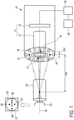
- Fig. 1 shows schematically and exemplarily a first embodiment of a colposcopy apparatus 10 for performing a colposcopy procedure.
- the colposcopy apparatus 10 comprises an imaging unit 11 which comprises an optics unit 12 having an optical axis 22 and an image acquiring unit 13 for acquiring an image 21 of a cervix 23 through the optics unit 12.
- the colposcopy apparatus 10 further comprises at least three, here, four light beam emitting units 14, 15, 16, 17 which are spaced apart from the optical axis 22.
- the four light beam emitting units 14, 15, 16, 17 are adapted to emit light beams that are coplanar with the optical axis 22 and that intersect on the optical axis 22 at a predefined distance d10 in front of the colposcopy apparatus 10, wherein not all of the emitted light beams lie in a same plane.
- the four light beam emitting units 14, 15, 16, 17 are arranged at the front end of the colposcopy apparatus 10, that is, the end that is aimed at the cervix 23 when performing the colposcopy procedure, here, at a ring-shaped element that also contains a plurality of lighting elements 18 for lighting the cervix 23.
- the emitted light beams produce a two-dimensional pattern of light spots 25, 26, 27, 28 on the tissue.
- the overall dimension of this two-dimensional pattern of light spots 25, 26, 27, 28 becomes smaller - ultimately converging into a single observable light spot - when the distance of the colposcopy apparatus 10 from the cervix 23 approaches the predefined distance d10, that is, the distance at which the emitted light beams intersect on the optical axis 22 in front of the colposcopy apparatus 10, making it easy to position the colposcopy apparatus 10 at the predefined distance d10 from the cervix 23.
- the shape of the two-dimensional pattern of light spots 25, 26, 27, 28, that is, the relative distances between the light spots 25, 26, 27, 28 on the cervical tissue also changes. Since this change of the shape of the two-dimensional pattern of light spots 25, 26, 27, 28 provides information about the orientation (both horizontally and vertically) of the colposcopy apparatus 10 with respect to the cervix 23, it makes it easier to find a position in which the colposcopy apparatus 10 is substantially perpendicular to the cervix 23, which may allow to image more of the cervix 23 than would be visible under more oblique orientations of the colposcopy apparatus 10, where parts of the FOV may be obstructed by a vaginal speculum 24.
- the optics unit 12 has a fixed focal distance corresponding to the predefined distance d10 at which the emitted light beams intersect on the optical axis 22 in front of the colposcopy apparatus 10.
- the imaging unit 11 can thus be focused on the cervix 23 by positioning the colposcopy apparatus 10 such that the light spots 25, 26, 27, 28 produced by the emitted light beams on the cervical tissue are observed as a single light spot.
- the image acquiring unit 13, here, comprises a CCD sensor having a pixel resolution of 640 x 480 with an aspect ratio of 4:3 and a density of 96 dpi, a bit depth of 24 bit (8 bit per R, G, B color channel) and a video frame rate of 30 to 60 fps.
- the four light beam emitting units 14, 15, 16, 17 arranged on the top, the left, the bottom, and the right with respect to the acquired image 21.
- the four light beam emitting units 14, 15, 16, 17 are arranged such that two of the emitted light beams lie in a first same plane (not shown in the figure) with the optical axis 22 and the other two of the emitted light beams lie in a second same plane (not shown in the figure) with the optical axis 22, wherein the first same plane is arranged horizontally with respect to the acquired image 21 and the second same plane is arranged vertically with respect to the acquired image 21.
- such an arrangement of the four light beam emitting units 14, 15, 16, 17 is particularly suited for imaging the outermost regions of the cervix 23, that is, the regions that are present at the farthest end of the cervical channel.
- the four light beam emitting units 14, 15, 16, 17, here, are arranged on a circle (shown in the figure as a stippled line) having a predefined diameter D10 and surrounding the optical axis 22.
- Fig. 2 shows schematically and exemplarily a situation in which the outermost regions of the cervix 23 are imaged with the colposcopy apparatus 10 shown in Fig. 1 .
- the user pans and tilts the colposcopy apparatus 10. If, in doing so, he/she also takes care to position the colposcopy apparatus 10 at the predefined distance d10 from the cervix 23 in order to focus the imaging unit 11 on the cervix 23, the positioning of the colposcopy apparatus 10 defines a slightly curved "predefined distance plane" PD10.
- one or more, here, one of the emitted light beams may become obscured by the vaginal speculum 24 when the colposcopy apparatus 10 is panned and tilted by the user. This is visualized by the large dotted circle drawn in the predefined distance plane.
- the light beam emitted by the light beam emitting unit 14 becomes obscured by the vaginal speculum 24.
- the light beams emitted from the three other light beam emitting units 15, 16, 17 do not become obscured by the vaginal speculum 24 and, thus, can still allow using the positioning support.
- the non-obscured light beams emitted by the light beam emitting units 15, 16, 17 still produce a two-dimensional pattern of light spots 25, 26, 28 on the cervical tissue (which converges into a single observable light spot when the imaging unit 11 is properly focused on the cervix 23).
- the predefined distance d10 is 25 cm with the predefined diameter D10 being smaller than or equal to 5 cm.
- the predefined diameter D10 should suitably be larger than 0 cm, for instance, larger than 1 cm or larger than 3 cm.
- the predefined diameter D10 is 4 cm.
- the arrangement of the four light beam emitting units 14, 15, 16, 17 is pairwise symmetric with respect to the optical axis 22, that is, respectively two of the emitted light beams lie in a same plane with the optical axis 22 and are oriented under the same angle.
- at least two, here, all of the emitted light beams have visually discernible colors, since with such a symmetric arrangement the use of discernible colors for at least two of the emitted light beams provides information about whether the colposcopy apparatus 10 is positioned too far away from or too close to the cervix 23.
- the colors of the emitted light beams are chosen such that they are easily visible to the human eye when seen against cervical tissue.
- the colposcopy apparatus 10 further comprises an image analysis unit 19 for analysing the acquired image 21 of the cervix 23 with respect to light spots 25, 26, 27, 28 produced by the emitted light beams on the cervical tissue to determine information about the positioning of the colposcopy apparatus 10 with respect to the cervix 23, and a user indication unit 20 for providing indications to a user of the colposcopy apparatus 10 to support the user in positioning the colposcopy apparatus 10 based on the determined information.
- the user indication unit 20, here, is adapted for displaying the acquired image 21 to the user and to visually provide the indications as a visual overlay (not shown in the figure) provided on the displayed image.
- the indications comprise first indications indicating whether the colposcopy apparatus 10 must be moved towards the cervix 23 or away from the cervix 23 to position the colposcopy apparatus 10 at a distance from the cervix 23 equal to the predefined distance d10.
- the first indications consist of quantitative information giving the deviation from the predefined distance d10 in terms of positive and negative numerical values, such as -2.5 cm or +0.7 cm.
- the first indications can also be plain directional indications like "forwards" and "backwards” or they can make use of signs that are associated with certain movement directions.
- the indications further comprise second indications indicating whether the colposcopy apparatus 10 is positioned such that the cervix 23 is within the DOF of the imaging unit 11.
- the second indications comprise a visual representation, here, a circle, of the DOF (not shown in the figure) overlaid on the displayed image.
- the second indications can be plain indications like "in” and "out” (of the DOF) or they can make use of signs that are associated with the cervix being either within or out-of the DOF.
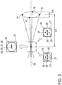
- Fig. 3 shows schematically and exemplarily how second indications are used to indicate whether the colposcopy apparatus 10 shown in Fig. 1 is positioned such that the cervix 23 is within the DOF of the imaging unit 11.
- the figure is similar to Fig. 1 but shows only the four light beam emitting units 14, 15, 16, 17 as well as the light beams emitted therefrom.
- the DOF of the imaging unit 11 is the range of distances in front of the colposcopy apparatus 10 for which, if the colposcopy apparatus 10 is positioned within this range of distances from the cervix 23, the acquired image 21 is still acceptably well focused.
- the size of the DOF depends on the specifics of the imaging unit 11, in particular, on the characteristics of the optics unit 12 and the image acquiring unit 13 (all not shown in the figure).
- the DOF is symmetrical with respect to the predefined distance d10.
- the colposcopy apparatus 10 is positioned at the predefined distance d10 from the cervix 23, the light spots 25, 26, 27, 28 produced by the emitted light beams on the cervical tissue are observed as a single light spot.
- the colposcopy apparatus 10 is positioned at a distance different from the predefined distance d10 from the cervix 23, the light spots 25, 26, 27, 28 produced by the emitted light beams produce a two-dimensional pattern of light spots 25, 26, 27, 28 on the tissue.
- the DOF is visually represented by a circle overlaid on the displayed image 21 (in the figure shown as a stippled circle), it can easily be decided whether the cervix 23 is within or out-of the DOF. If the light spots 25, 26, 27, 28 produced by the emitted light beams are within the circle, the cervix 23 is within the DOF; if they are out-of the circle, the cervix 23 is out-of the DOF.
- the optics unit 12 has a fixed focal distance corresponding to the predefined distance d10 at which the emitted light beams intersect on the optical axis 22 in front of the colposcopy apparatus 10, in other embodiments, the optics unit 12 may comprise at least one variable-focus lens based, for instance, on liquids, for adjusting the focal distance of the imaging unit 11.
- the image analysis unit 19 may - additionally or alternatively - be adapted to analyse the acquired image 21 of the cervix 23 with respect to light spots 25, 26, 27, 28 produced by the emitted light beams on the cervical tissue to determine the distance of the colposcopy apparatus 10 from the cervix 23, wherein the colposcopy apparatus 10 may be adapted to adjust the focal distance and/or the zoom of the imaging unit 11 based on the determined distance.
- the focal distance and/or the zoom of the imaging unit 11 By adjusting the focal distance and/or the zoom of the imaging unit 11 based on the determined distance, it can then possible to acquire a sharp image of the cervix 23, preferably showing the cervix 23 such that it substantially just completely fills the acquired image 21, even if the colposcopy apparatus 10 is positioned at a distance from the cervix 23 different from the predefined distance d10.
- This can be particularly helpful, for instance, when the user pans and tilts the colposcopy apparatus 10 to image the outermost regions of the cervix 23, as described above, since due to the panning and tilting the positioning of the colposcopy apparatus 10 may deviate from the predefined distance d10.
- Fig. 4 shows a graph exemplarily illustrating suitable values for adjusting the focal distance and/or the zoom of the imaging unit 11 of the colposcopy apparatus 10 shown in Fig. 1 based on the determined distance of the colposcopy apparatus 10 from the cervix 23.
- suitable values for adjusting the focal distance and the zoom of the imaging unit 11 have been calculated (y-axis).
- the values are specific to the Goldway SLC-2000B digital video colposcope.
- d represents the distance of the colposcopy apparatus 10 from the cervix 23
- F represents the corresponding focus value
- sqrt() denotes the square root operation
- Z represents the corresponding zoom value
- R 2 is a quantifying parameter to showcase a "goodness of fit”. (The value ranges from 0, which is the worst fit, to 1, which is best fit. This means that the closer the value is to 1, the better the curve fits to the data points.)
- the values for adjusting the focal distance and the zoom of the imaging unit 11 have been calculated, in this example, such that the size of the cervix 23 shown in the acquired image 21 is kept constant (here, particularly, such that the cervix 23 substantially just completely fills the acquired image 21) for changes in the determined distance, as shown at the top of the figure.
- This has the advantage that the user can be constantly provided with a sharp acquired image showing the cervix 23 or a fraction thereof at the same size even if changes in the distance between the colposcopy apparatus 10 and the cervix 23 occur during the colposcopy procedure, for instance, due to slight movements of the patient. It can therefore be easier for the user to visually check the surface of the cervix 23 for abnormalities.
- the calculated values for adjusting the focal distance and the zoom of the imaging unit 11 are also shown in the following Table 1.
- the adjustment of the focal distance and the zoom of the imaging unit 11 may comprise purely optical techniques or a combination of optical and digital techniques.
- the optics unit 12 may comprise at least one variable-focus lens based, for instance, on liquids, for adjusting the focal distance of the imaging unit 11 and the adjustment of the zoom may be performed by means of digital zooming and/or by the use of different zoom lenses.
- Fig. 5 shows schematically and exemplarily a second embodiment of a colposcopy apparatus 50 for performing a colposcopy procedure.
- the colposcopy apparatus 50 is similar to the colposcopy apparatus 10 shown in Fig. 1 .
- it also comprises an imaging unit 51 which comprises an optics unit 52 having an optical axis 62 and an image acquiring unit 53 for acquiring an image 61 of a cervix 63 through the optics unit 52.
- the colposcopy apparatus 50 comprises an infrared light distance sensing unit 55, 57 comprising an infrared light beam emitter 55 and an infrared light receiver 57 spaced apart from the optical axis 62.
- the infrared light beam emitter 55 is adapted to emit an infrared light beam that is coplanar with the optical axis 62 and that intersects on the optical axis 62 at a predefined distance d50 in front of the colposcopy apparatus 50, and the infrared light receiver 57 lies in a same plane with the emitted infrared light beam and the optical axis 62 and is adapted to receive the emitted infrared light beam after it has been reflected.
- the infrared light distance sensing unit 55, 57 is adapted to sense a distance based on the emitted and reflected infrared light beam.
- the infrared light beam emitter 55 and the infrared light receiver 57 are arranged at the front end of the colposcopy apparatus 50, that is, the end that is aimed at the cervix 63 when performing the colposcopy procedure, here, at a ring-shaped element that also contains a plurality of lighting elements 58 for lighting the cervix 63.
- the image acquiring unit 53 here, comprises a CCD sensor having a pixel resolution of 640 x 480 with an aspect ratio of 4:3 and a density of 96 dpi, a bit depth of 24 bit (8 bit per R, G, B color channel) and a video frame rate of 30 to 60 fps.
- the infrared light beam emitter 55 and the infrared light receiver 57 are arranged on a circle (shown in the figure as a stippled line) having a predefined diameter D50 and surrounding the optical axis 62.
- the predefined distance d50 is 25 cm with the predefined diameter D50 being smaller than or equal to 5 cm.
- the emitted infrared light beams can converge on the cervix 63 without becoming obstructed by the vaginal speculum 64 having a typical inner diameter of 1.6 cm and a length of 8 cm (corresponding to a normal depth of the vaginal channel).
- the predefined diameter D50 should suitably be larger than 0 cm, for instance, larger than 1 cm or larger than 3 cm.
- the predefined diameter D50 is 4 cm.
- the colposcopy apparatus 50 comprises a user indication unit 60 for providing indications to a user of the colposcopy apparatus 50 to support the user in positioning the colposcopy apparatus 50 based on the currently sensed distance.
- the colposcopy apparatus 50 is adapted to provide an initialization phase during which the infrared light distance sensing unit 55, 57 repeatedly senses the distance to generate a plurality of sensed distances, while a user of the colposcopy apparatus 50 shall move the colposcopy apparatus 50 in substantially a plane in front of the cervix 63, to identify a working distance of the colposcopy apparatus 50 from the cervix 63 based on the plurality of sensed distances, and to store the identified working distance, wherein the indications are further based on the stored working distance.
- the user indication unit 60 here, is adapted for displaying the acquired image 61 to the user and to visually provide the indications as a visual overlay (not shown in the figure) provided on the displayed image.
- the indications consist of quantitative information giving the deviation of the currently sensed distance from the stored working distance in terms of positive and negative numerical values, such as -1.5 cm or +0.9 cm. Given this information, the user can then be able to more easily tell whether the colposcopy apparatus 50 is aimed at the cervix 63 or not (as described above).
- the colposcopy apparatus 50 further comprises an image analysis unit 59 for analysing the acquired image 61 of the cervix 63 to determine information about the focal distance and/or the zoom of the imaging unit 51, wherein the colposcopy apparatus 50 is adapted, during the initialization phase, when the colposcopy apparatus 50 is positioned with respect to the cervix 63 such that the currently sensed distance matches the stored working distance, to adjust the focal distance and the zoom of the imaging unit 51 based on the determined information for the currently acquired image 61 of the cervix 63 and, after adjusting the focal distance and the zoom of the imaging unit 51, to store the currently acquired image 61 of the cervix 63.
- an image analysis unit 59 for analysing the acquired image 61 of the cervix 63 to determine information about the focal distance and/or the zoom of the imaging unit 51
- the colposcopy apparatus 50 is adapted, during the initialization phase, when the colposcopy apparatus 50 is positioned with respect to the cervix 63 such that the currently sensed distance matches
- the information about the focal distance and the zoom of the imaging unit 51 is determined, here, by image analysis techniques that are able to assess an amount of blur of the currently acquired image 61 and to detect the cervix 63 or a fraction thereof in the currently acquired image 61. Based on the assessed amount of blur of the currently acquired image 61 and the detected cervix 63 or fraction thereof in the currently acquired image 61, the focal distance and the zoom of the imaging unit 51 are then iteratively adjusted.
- a sharp image of the cervix 63 which shows the cervix 63 such that it substantially just completely fills the acquired image 61, is acquired and this image 61 is stored as a kind of "gold standard" for later acquired images 61 of the cervix 63.
- the adjustment of the focal distance and the zoom of the imaging unit 51 comprises a combination of optical and digital techniques.
- the optics unit 52 comprises at least one variable-focus lens (not shown in the figure) based, for instance, on liquids, for adjusting the focal distance of the imaging unit 51 and the adjustment of the zoom is performed by means of digital zooming and by the use of different zoom lenses (not shown in the figure).
- the image analysis unit 59 is adapted to determine further information about a difference between the currently acquired image 61 of the cervix 63 and the stored image of the cervix 63
- the colposcopy apparatus 50 is adapted to provide a colposcopy procedure phase during which the focal distance and the zoom of the imaging unit 51 are adjusted based on the determined further information.
- the further information about a difference between the currently acquired image 61 of the cervix 63 and the stored image of the cervix 63 is determined, here, by image analysis techniques that perform a correlation between the currently acquired image 61 of the cervix 63 and the stored image of the cervix 63, wherein the focal distance and/or the zoom of the imaging unit 51 are adjusted to minimize the difference.
- the colposcopy apparatus 50 can be adapted to adjust the focal distance and/or the zoom of the imaging unit 51 based on the currently sensed distance.
- the colposcopy apparatus 50 may comprise a predefined look-up table storing for a range of currently sensed distances of the colposcopy apparatus 50 from the cervix 63 suitable values for adjusting the focal distance and/or the zoom of the imaging unit 51.
- the range of currently sensed distances may comprise, for instance, distances of the colposcopy apparatus 50 from the cervix ranging from 20 cm to 30 cm. Suitable values for adjusting the focal distance and the zoom of the imaging unit 51 may be calculated as described above.
- a single unit or device may fulfill the functions of several items recited in the claims.
- the mere fact that certain measures are recited in mutually different dependent claims does not indicate that a combination of these measures cannot be used to advantage.
- a computer program may be stored/distributed on a suitable medium, such as an optical storage medium or a solid-state medium, supplied together with or as part of other hardware, but may also be distributed in other forms, such as via the Internet or other wired or wireless telecommunication systems.
- a suitable medium such as an optical storage medium or a solid-state medium, supplied together with or as part of other hardware, but may also be distributed in other forms, such as via the Internet or other wired or wireless telecommunication systems.
- the present invention relates to a colposcopy apparatus for performing a colposcopy procedure.
- the colposcopy apparatus comprises an imaging unit comprising an optics unit having an optical axis and an image acquiring unit for acquiring an image of a cervix through the optics unit, and at least three light beam emitting units spaced apart from the optical axis, wherein the at least three light beam emitting units are adapted to emit light beams that are coplanar with the optical axis and that intersect on the optical axis at a predefined distance in front of the colposcopy apparatus, wherein not all of the emitted light beams lie in a same plane.
Landscapes
- Health & Medical Sciences (AREA)
- Life Sciences & Earth Sciences (AREA)
- Surgery (AREA)
- Engineering & Computer Science (AREA)
- Veterinary Medicine (AREA)
- Public Health (AREA)
- Biophysics (AREA)
- General Health & Medical Sciences (AREA)
- Pathology (AREA)
- Animal Behavior & Ethology (AREA)
- Physics & Mathematics (AREA)
- Biomedical Technology (AREA)
- Heart & Thoracic Surgery (AREA)
- Medical Informatics (AREA)
- Molecular Biology (AREA)
- Radiology & Medical Imaging (AREA)
- Optics & Photonics (AREA)
- Nuclear Medicine, Radiotherapy & Molecular Imaging (AREA)
- Gynecology & Obstetrics (AREA)
- Reproductive Health (AREA)
- Signal Processing (AREA)
- Endoscopes (AREA)
- Length Measuring Devices By Optical Means (AREA)
- Dental Tools And Instruments Or Auxiliary Dental Instruments (AREA)
Description
- The present invention relates to the medical field and, in particular, relates to a colposcopy apparatus for performing a colposcopy procedure.
- Cervical cancer is the second most common cancer in women. In order to visually check the surface of the cervix for abnormalities, a colposcopy procedure is performed, wherein a device called a vaginal speculum is inserted into the vagina and the cervix is examined by a gynecologist using an instrument called a colposcope having a light and a magnifying lens, which stays outside the body and allows the gynecologist to see any abnormalities. As part of the colposcopy procedure, the gynecologist may initially clean the cervix with normal saline to remove any secretions. This may be followed by looking at the cervix under a green filter for determining the presence of blood vessels and other vascular patterns like punctuations and mosaics. Thereafter, a further step of applying a diluted acetic acid which turns the color of the abnormal cervical tissue to white may follow, wherein the gynecologist maps the time of appearance of this Aceto-while effect and the duration for which the Aceto-whiteness stays. After this step, the gynecologist may further apply 5 % Lugol's iodine and check whether the cervical tissue shows a partial or complete uptake of the iodine.
- To focus the colposcope and, thus, to obtain sharp images when performing the colposcopy procedure, the region of interest, here, the cervix, must be at the correct focal distance (i.e., focal length) from the colposcope. This focal distance, which corresponds to the working distance, is typically between 20 cm to 30 cm long. Shorter focal distances require the colposcope to be closer to the cervix, making it difficult to use other clinical instruments like a cotton swab, stains, therapy devices and the like when performing the colposcopy procedure. Longer focal distances, one the other hand, can make it uncomfortable for the gynecologist to perform the colposcopy procedure, in particular, if he/she has comparably short arms. In the clinical practice, positioning the colposcope at the proper working distance can be quite difficult due to the anatomy of the vagina as well as the slight movements of the cervix. Moreover, focus may be lost during a longer colposcopy procedure due to movements of the patient.
-
US 2006/0215406 discloses a colposcope for examining cervical tissue.WO 2014/006549 discloses a system for imaging a patient's interior.US 2010/0025566 discloses a system for the acquisition of high-quality focused tissue image data.US 2012/0249764 discloses a cervical, fetal-membrane, and amniotic examination and assessment device. -
US 6,277,067 B1 discloses a hand-held colposcopy assembly capable of producing a digital image of the cervix. The colposcopy assembly comprises first and second light emitters which are able to generate emitted light beams visible to the human eye when seen against human tissue. The first and second light emitters are located on opposite sides of a fixed focus objective lens through which a CCD sensor based camera (charge-coupled device) can capture the digital image. Moreover, the first and second light emitters are oriented such that the emitted light beams intersect on the optical axis of the objective lens at the optimum focal plane of the camera, whereby, as the colposcopy assembly is aimed at cervical tissue of the patient, the emitted light beams produce first and second light spots on the tissue, the first and second light spots being observed by the gynecologist as a single light spot when the cervix is properly focused in the camera. - The configuration with the first and second light emitters supports a gynecologist in positioning the disclosed colposcopy assembly at the proper working distance from the cervix. However, it would also be helpful for the gynecologist if during the process of positioning the colposcope, he/she would additionally be supported in finding a position and/or configuration of the colposcope that allows seeing a maximum amount of the cervix. This problem is not addressed in the cited prior art.
- It is therefore an object of the present invention to provide a colposcopy apparatus for performing a colposcopy procedure, which allows better supporting a user, for instance, a gynecologist, in positioning and/or configuring the colposcopy apparatus for performing the colposcopy procedure. The present invention is defined in and by the appended claims.
- There is also described herein a colposcopy apparatus for performing a colposcopy procedure, wherein the colposcopy apparatus comprises:
- an imaging unit comprising an optics unit having an optical axis and an image acquiring unit for acquiring an image of a cervix through the optics unit, and
- at least three light beam emitting units spaced apart from the optical axis, wherein the at least three light beam emitting units are adapted to emit light beams that are coplanar with the optical axis and that intersect on the optical axis at a predefined distance in front of the colposcopy apparatus, wherein not all of the emitted light beams lie in a same plane.
- Since the colposcopy apparatus comprises at least three light beam emitting units spaced apart from the optical axis, and since the at least three light beam emitting units are adapted to emit light beams that are coplanar with the optical axis and that intersect on the optical axis at a predefined distance in front of the colposcopy apparatus, wherein not all of the emitted light beams lie in a same plane, when the colposcopy apparatus is aimed at cervical tissue during the process of positioning the colposcopy apparatus, the emitted light beams produce a two-dimensional pattern of light spots on the tissue. The overall dimension of this two-dimensional pattern of light spots becomes smaller - ultimately converging into a single observable light spot - when the distance of the colposcopy apparatus from the cervix approaches the predefined distance, that is, the distance at which the emitted light beams intersect on the optical axis in front of the colposcopy apparatus, making it easy to position the colposcopy apparatus at the predefined distance from the cervix. In addition, when the orientation of the colposcopy apparatus changes with respect to the cervix, the shape of the two-dimensional pattern of light spots, that is, the relative distances between the light spots on the cervical tissue, also changes. Since this change of the shape of the two-dimensional pattern of light spots provides information about the orientation (both horizontally and vertically) of the colposcopy apparatus with respect to the cervix, it makes it easier to find a position in which the colposcopy apparatus is substantially perpendicular to the cervix, which may allow to image more of the cervix than would be visible under more oblique orientations of the colposcopy apparatus, where parts of the field of view (FOV) may be obstructed by a vaginal speculum.
- It shall be noted that the provision of at least three light beam emitting units, as described above, can further be advantageous when the user wants to image the outermost regions of the cervix, that is, the regions that are present at the farthest end of the cervical channel. For instance, if the user wants to image the region at the 12 o' clock position of the cervix, keeping it in the center of the acquired image for a more detailed analysis of potential abnormalities, he/she would usually pan and tilt the colposcopy apparatus. The larger number of light beam emitting units can still allow using the positioning support provided by the emitted light beams even if one or more of the emitted light beams become obscured by the vaginal speculum when the colposcopy apparatus is panned and tilted by the user.
- The optics unit can be an optics unit having a fixed focal distance corresponding to the predefined distance at which the emitted light beams intersect on the optical axis in front of the colposcopy apparatus. In this case, the imaging unit can be focused on the cervix by positioning the colposcopy apparatus such that the light spots produced by the emitted light beams on the cervical tissue are observed as a single light spot.
- The image acquiring unit can comprise a CCD sensor with a suitable aspect ratio, pixel resolution and bit depth. For instance, a suitable CCD sensor can have a pixel resolution of 640 x 480 with an aspect ratio of 4:3 and a density of 96 dpi (dots per inch), a bit depth of 24 bit (8 bit per R, G, B color channel) and a video frame rate of 30 to 60 fps (frames per second). Of course, the image acquiring unit can also comprise another type of sensor, for instance, a suitable CMOS sensor (complementary metal oxide semiconductor) with comparable specifications.
- The at least three light beam emitting units are preferably visual light beam emitting units, for instance, laser light beam emitting units, such as suitable laser diodes. However, also other types of light beam emitting units can be used as long as such units are able to emit suitably focused light beams. If non-coherent light is used, suitable focusing optics may be provided in order to focus the light into beams. It can be foreseen that the user can switch on and off the at least three light beam emitting units using a suitable user interface.
- It is preferred to that the at least three light beam emitting units comprise four light beam emitting units that are arranged on the top, the left, the bottom, and the right with respect to the acquired image.
- In particular, the four light beam emitting units can be arranged such that two of the emitted light beams lie in a first same plane with the optical axis and the other two of the emitted light beams lie in a second same plane with the optical axis, wherein the first same plane is arranged horizontally with respect to the acquired image and the second same plane is arranged vertically with respect to the acquired image. Such an arrangement of the four light beam emitting units is particularly suited for imaging the outermost regions of the cervix, as described above. Of course, the at least three light beam emitting units may also comprise more than four light beam emitting units, which can further improve the suitability of the colposcopy apparatus for imaging the outermost regions of the cervix.
- It is further preferred that at least two of the emitted light beams have visually discernible colors.
- This is particularly advantageous if the arrangement of the at least three light beam emitting units is pairwise symmetric with respect to the optical axis, that is, if respectively two of the emitted light beams lie in a same plane with the optical axis and are oriented under the same angle, since with such a symmetric arrangement the use of discernible colors for at least two of the emitted light beams provides information about whether the colposcopy apparatus is positioned too far away from or too close to the cervix.
- For instance, let us assume a symmetric arrangement in which one of the emitted light beams has a color that is visually discernible from the color (or colors) of the other emitted light beams. The location of the light spot produced by that emitted light beam on the cervical tissue in the acquired image then depends on the distance of the colposcopy apparatus from the cervix. If the colposcopy apparatus is positioned too far away from the cervix, that is, the distance of the colposcopy apparatus from the cervix is larger than the predefined distance, the light spot is located in the acquired image at a first side relative to the location of the focal point (that is, the position at which the optical axis intersects the acquired image). On the other hand, if the colposcopy apparatus is positioned too close to the cervix, that is, the distance of the colposcopy apparatus from the cervix is smaller than the predefined distance, the light spot is located in the acquired image at a second side, opposite to the first side, relative to the position of the focal point. Thus, by determining on which side relative to the focal point the light spot is located, it can be determined whether the colposcopy apparatus is positioned too far away from or too close to the cervix.
- The colors of the emitted light beams are preferably chosen such that they are easily visible to the human eye when seen against cervical tissue. In one preferred example, the at least three light beam emitting units are just three light beam emitting units and the emitted light beams have a red color, a green color, and a blue color, respectively. In this case, when the colposcopy apparatus is positioned at a distance from the cervix that equals the predefined distance, a single white light spot can be observed on the cervical tissue.
- It is preferred that the at least three light beam emitting units are arranged on a circle having a predefined parameter and surrounding the optical axis, wherein the predefined distance is preferably between 23 cm and 27 cm with the predefined diameter being smaller than or equal to 4.6 cm to 5.4 cm, wherein the predefined distance is more preferably between 24 cm and 26 cm with the predefined diameter being smaller than or equal to 4.8 cm to 5.2 cm, wherein the predefined distance is most preferred 25 cm with the predefined diameter being smaller than or equal to 5 cm.
- A predefined distance of 25 cm is particularly advantageous since it allows the colposcopy apparatus to be far enough away from the cervix such that other clinical instruments like a cotton swab, stains, therapy devices and the like can easily be used when performing the colposcopy procedure, but still close enough to the cervix such that the user can comfortably perform the colposcopy procedure, even if he/she has comparably short arms. With this predefined distance, the predefined diameter is preferably smaller than or equal to 5 cm since in this case all the emitted light beams can converge on the cervix without becoming obstructed by a vaginal speculum having a typical inner diameter of 1.6 cm and a length of 8 cm (corresponding to a normal depth of the vaginal channel). Of course, the predefined diameter should suitably be larger than 0 cm, for instance, larger than 1 cm or larger than 3 cm.
- The upper values for the predefined diameter have been calculated above according to the following equation Dlaser = d · (Dspeculum / Dvaginal_channel), where Dlaser represents the predefined diameter, d represents the predefined distance, Dspeculum represents the inner diameter of the vaginal speculum and Dvaginal_channel, represents the depth of the vaginal channel. With this equation, other combinations of the predefined distance and the predefined parameter may be calculated, for instance, for vaginal specula having different (smaller or larger) inner diameters.
- The colposcopy apparatus may further comprise:
- an image analysis unit for analysing the acquired image of the cervix with respect to light spots produced by the emitted light beams on the cervical tissue to determine information about the positioning of the colposcopy apparatus with respect to the cervix,
- a user indication unit for providing indications to a user of the colposcopy apparatus to support the user in positioning the colposcopy apparatus based on the determined information.
- By providing such an image analysis unit, the information provided by the two-dimensional pattern of light spots produced by the emitted light beams on the cervical tissue can be analysed and, preferably, quantified in the acquired image. It can then be possible when the colposcopy apparatus is aimed at the cervical tissue during the process of positioning the colposcopy apparatus to - qualitatively or quantitatively - determine the distance of the colposcopy apparatus from the cervix and/or the orientation of the colposcopy apparatus with respect to the cervix. Based on the determined information about the positioning of the colposcopy apparatus with respect to the cervix, the user of the colposcopy apparatus can then be provided with indications supporting him/her in positioning the colposcopy apparatus.
- The user indication unit can be adapted for displaying the acquired image to the user and to visually provide the indications with or in addition to the displayed image, for instance, as a visual overlay provided on the displayed image. However, it is also possible that the user indication unit is adapted to provide the indications to the user by other means, for example, in an audible or tactile manner. In these cases, the user indication unit can comprise suitable indication elements, such as one or more audio transducer elements or a vibration element.
- It is preferred that the indications comprise first indications indicating whether the colposcopy apparatus must be moved towards the cervix or away from the cervix to position the colposcopy apparatus at a distance from the cervix equal to the predefined distance.
- Such first indications about the direction for moving the colposcopy apparatus are particularly useful for supporting the user in quickly positioning the colposcopy apparatus at a distance from the cervix equal to the predefined distance. The first indications can be plain directional indications like "forwards" and "backwards", but they can also comprise or consist of quantitative information, for instance, they can give the deviation from the predefined distance in terms of positive and negative numerical values, such as -2.5 cm or +0.7 cm. Of course, it is also possible that the first indications make use of signs that are associated with certain movement directions. For instance, a green light may be associated with a situation in which the colposcopy apparatus must be moved towards the cervix to position the colposcopy apparatus at a distance from the cervix equal to the predefined distance and a red light may be associated with a situation in which the colposcopy apparatus must be moved away from the cervix.
- It is further preferred that the indications comprise second indications indicating whether the colposcopy apparatus is positioned such that the cervix is within the depth of field (DOF) of the imaging unit.
- The DOF of the imaging unit is the range of distances in front of the colposcopy apparatus for which, if the colposcopy apparatus is positioned within this range of distances from the cervix, the acquired image is still acceptably well focused. The size of the DOF depends on the specifics of the imaging unit, in particular, on the characteristics of the optics unit and the image acquiring unit. Such second indications about the positioning of the colposcopy apparatus are particularly useful since they allow the user to tolerate a certain deviation when trying to position the colposcopy apparatus at a distance from the cervix equal to the predefined distance and still acquire a sharp image. The second indications can be plain indications like "in" and "out" (of the DOF), but they can also make use of signs that are associated with the cervix being either within or out-of the DOF. Preferably, however, the user indication unit is adapted to display the acquired image to the user, wherein the second indications comprise a visual representation of the DOF displayed with the acquired image. For instance, in the case that the at least three light beam emitting units are arranged on a circle having a predefined parameter and surrounding the optical axis, the DOF can be visually represented by a circle overlaid on the displayed image. Therewith, it can easily be decided whether the cervix is within or out-of the DOF. If the light spots produced by the emitted light beams are within the circle, the cervix is within the DOF; if they are out-of the circle, the cervix is out-of the DOF.
- The colposcopy apparatus may further comprise:
- an image analysis unit for analysing the acquired image of the cervix with respect to light spots produced by the emitted light beams on the cervical tissue to determine the distance of the colposcopy apparatus from the cervix,
- By providing such an image analysis unit, the information provided by the two-dimensional pattern of light spots produced by the emitted light beams on the cervical tissue can be analysed in the acquired image and the distance of the colposcopy apparatus from the cervix can be determined. By adjusting the focal distance and/or the zoom of the imaging unit based on the determined distance, it can then be possible to acquire a sharp image of the cervix, preferably showing the cervix such that it substantially just completely fills the acquired image, even if the colposcopy apparatus is positioned at a distance from the cervix different from the predefined distance. This can be particularly helpful, for instance, when the user pans and tilts the colposcopy apparatus to image the outermost regions of the cervix, as described above, since due to the panning and tilting the positioning of the colposcopy apparatus may deviate from the predefined distance.
- The adjustment of the focal distance and/or the zoom of the imaging unit may comprise purely optical techniques or a combination of optical and digital techniques. For instance, the optics unit may comprise at least one variable-focus lens based, for instance, on liquids, for adjusting the focal distance of the imaging unit and the adjustment of the zoom may be performed by means of digital zooming and/or by the use of different zoom lenses. The colposcopy apparatus may comprise a predefined look-up table storing for a range of determined distances of the colposcopy apparatus from the cervix suitable values for adjusting the focal distance and/or the zoom of the imaging unit. The range of determined distances may comprise, for instance, distances of the colposcopy apparatus from the cervix ranging from 20 cm to 30 cm.
- It can also be possible that different sets of values for adjusting the zoom of the imaging unit are provided within the colposcopy apparatus for choosing between different magnifications of the cervix. For instance, with a first set of values the cervix may always be shown such that it substantially just completely fills the acquired image whereas with a second set of values the cervix may always be shown with twice the magnification, effectively resulting in only a magnified fraction of the cervix being shown in the acquired image. Of course, it can be foreseen that the user can select between such different sets of values for adjusting the zoom of the imaging unit using a suitable user interface. Also, it shall be understood that with different sets of values for adjusting the zoom also corresponding different sets of values for adjusting the focal distance may be provided.
- It is preferred that for changes in the determined distance, the focal distance and/or the zoom of the imaging unit are adjusted such that the size of the cervix or of a fraction thereof shown in the acquired image is kept constant.
- This has the advantage that the user can be constantly provided with a sharp acquired image showing the cervix or a fraction thereof at the same size even if changes in the distance between the colposcopy apparatus and the cervix occur during the colposcopy procedure, for instance, due to slight movements of the patient. It can therefore be easier for the user to visually check the surface of the cervix for abnormalities.
- There is also described herein a colposcopy apparatus for performing a colposcopy procedure, wherein the colposcopy apparatus comprises:
- an imaging unit comprising an optics unit having an optical axis and an image acquiring unit for acquiring an image of a cervix through the optics unit,
- an infrared light distance sensing unit comprising an infrared light beam emitter and an infrared light receiver spaced apart from the optical axis, wherein the infrared light beam emitter is adapted to emit an infrared light beam that is coplanar with the optical axis and that intersects on the optical axis at a predefined distance in front of the colposcopy apparatus, wherein the infrared light receiver lies in a same plane with the emitted infrared light beam and the optical axis and is adapted to receive the emitted infrared light beam after it has been reflected, and wherein the infrared light distance sensing unit is adapted to sense a distance based on the emitted and reflected infrared light beam, and
- a user indication unit for providing indications to a user of the colposcopy apparatus to support the user in positioning the colposcopy apparatus based on the currently sensed distance.
- It has occurred to the inventors that experienced users appear to be generally quite good in roughly positioning the colposcopy apparatus at a proper working distance, for instance, 25 cm (cf. above), from the cervix, but that it is more difficult to position the colposcopy apparatus such that it is actually aimed at the cervix. In order to support the user in this later respect, prior knowledge about the patient's anatomy of interest can be used. In particular, it is the case that the cervix is located at the farthest end of the vaginal canal (which normally has a depth of about 8 cm). Thus, if the user roughly positions the colposcopy apparatus at the proper working distance, the currently sensed distance should be substantially equal to the proper working distance if the colposcopy apparatus is aimed at the cervix, whereas it should generally be much smaller if the colposcopy apparatus is not aimed at the cervix, for instance, if it is aimed at a vaginal speculum, at another body part of the patient, et cetera. This effect can be used by the user indication unit for providing indications to the user to support the user in positioning the colposcopy apparatus.
- The indications can comprise or consist of quantitative information, for instance, they can give the currently sensed distance in terms of a numerical value, such as 23.7 cm or 18.2 cm. Given this information, the user can then be able to tell based on his/her experience whether the colposcopy apparatus is aimed at the cervix or not. Alternatively, the indications can also be plain indications like "Yes" and "No", wherein "Yes" means that the colposcopy apparatus is aimed at the cervix and "No" means that the colposcopy apparatus is not aimed at the cervix. These two situations may be distinguished by the user indication unit by comparing the currently sensed distance with a suitably defined threshold, for instance, 20 cm. Of course, instead of plain indications, one can also make use of signs, such as a green light and a red light, that are associated with these two situations.
- The user indication unit can be adapted for displaying the acquired image to the user and to visually provide the indications with or in addition to the displayed image, for instance, as a visual overlay provided on the displayed image. However, it is also possible that the user indication unit is adapted to provide the indications to the user by other means, for example, in an audible or tactile manner. In these cases, the user indication unit can comprise suitable indication elements, such as one or more audio transducer elements or a vibration element.
- The image acquiring unit can comprise a CCD sensor with a suitable aspect ratio, pixel resolution and bit depth. For instance, a suitable CCD sensor can have a pixel resolution of 640 x 480 with an aspect ratio of 4:3 and a density of 96 dpi (dots per inch), a bit depth of 24 bit (8 bit per R, G, B color channel) and a video frame rate of 30 to 60 fps (frames per second). Of course, the image acquiring unit can also comprise another type of sensor, for instance, a suitable CMOS sensor (complementary metal oxide semiconductor) with comparable specifications.
- The colposcopy apparatus may be adapted to provide an initialization phase during which the infrared light distance sensing unit repeatedly senses the distance to generate a plurality of sensed distances, while a user of the colposcopy apparatus shall move the colposcopy apparatus in substantially a plane in front of the cervix, to determine a working distance of the colposcopy apparatus from the cervix based on the plurality of sensed distances, and to store the working distance, wherein the indications are further based on the stored working distance.
- The infrared light distance sensing unit senses the distance based on the reflected infrared light beam. However, there is generally no direct indication at which surface - of the cervix, of the vaginal speculum, of another body part of the patient, et cetera - the infrared light beam has been reflected, that is, to which object the sensed distance actually relates. In order to make the positioning support more robust, in particular, for less experiences users who are not that good in positioning the colposcopy apparatus at a proper working distance from the cervix, for instance, who are not able to tell with good accuracy how far away from the cervix they have positioned the colposcopy apparatus, the initialization phase can be performed on the patient before performing the actual colposcopy procedure. In this phase, when the user moves the colposcopy apparatus in substantially a plane in front of the cervix, the "actual" working distance of the colposcopy apparatus from the cervix can be determined based on the plurality of sensed distances. In particular, due to the above-discussed characteristics of the patient's anatomy of interest, the working distance of the colposcopy apparatus will ideally correspond to the largest sensed distance from among the plurality of sensed distances. This distance may therefore be stored as the working distance of the colposcopy apparatus from the cervix. The indications provided by the user indication unit to the user to support the user in positioning the colposcopy apparatus can then be further based on the stored working distance. For instance, they can comprise or consist of quantitative information, for instance, they can give the deviation of the currently sensed distance from the stored working distance in terms of positive and negative numerical values, such as -1.5 cm or +0.9 cm. Given this information, the user can then be able to more easily tell whether the colposcopy apparatus is aimed at the cervix or not.
- It is preferred that the colposcopy apparatus further comprises:
- an image analysis unit for analysing the acquired image of the cervix to determine information about the focal distance and/or the zoom of the imaging unit,
- The information about the focal distance and/or the zoom of the imaging unit can be determined, for instance, by image analysis techniques that are able to assess an amount of blur of the currently acquired image and/or to detect the cervix or a fraction thereof in the currently acquired image. Based on the assessed amount of blur of the currently acquired image, the focal distance of the imaging unit may then be iteratively adjusted. Additionally or alternatively, the zoom of the imaging unit may be adjusted, for instance, iteratively, based on the detected cervix or fraction thereof in the currently acquired image. By adjusting the focal distance and/or the zoom of the imaging unit, it can possible to acquire a sharp image of the cervix, preferably showing the cervix such that it substantially just completely fills the acquired image, and to store this image as a kind of "gold standard" for later acquired images of the cervix.
- The adjustment of the focal distance and/or the zoom of the imaging unit may comprise purely optical techniques or a combination of optical and digital techniques. For instance, the optics unit may comprise at least one variable-focus lens based, for instance, on liquids, for adjusting the focal distance of the imaging unit and the adjustment of the zoom may be performed by means of digital zooming and/or by the use of different zoom lenses.
- It is further preferred that the image analysis unit is adapted to determine further information about a difference between the currently acquired image of the cervix and the stored image of the cervix, and wherein the colposcopy apparatus is adapted to provide a colposcopy procedure phase during which the focal distance and/or the zoom of the imaging unit are adjusted based on the determined further information.
- By adjusting, during the "actual" colposcopy procedure phase, the focal distance and/or the zoom of the imaging unit based on the determined further information, it can be possible to acquire a sharp image of the cervix, preferably showing the cervix such that it substantially just completely fills the acquired image, even if the colposcopy apparatus is positioned at a distance from the cervix different from the stored working distance. This can be particularly helpful, for instance, since due to the different steps performed as part of the colposcopy procedure (that is, cleaning, Aceto-whiteness test, iodine uptake test, et cetera), the positioning of the colposcopy apparatus may deviate from the stored working distance. The further information about a difference between the currently acquired image of the cervix and the stored image of the cervix can be determined, for instance, by image analysis techniques that perform a matching or correlation between the currently acquired image of the cervix and the stored image of the cervix, wherein the focal distance and/or the zoom of the imaging unit can be adjusted to minimize the difference. Since, during the colposcopy procedure phase, the currently acquired image due of the cervix also varies in color due to the application of the diluted acetic acid and the 5 % Lugol's iodine, the matching or the correlation should be robust to such variations. For instance, the matching or the correlation may be performed in a transformed domain (cf., for instance, Matungka R. et al., "Image Registration Using Adaptive Polar Transform", in IEEE Transactions on Inage Processing, Vol. 18, No. 10, October 2009, pages 2340 to 2354).
- The colposcopy apparatus may be adapted to adjust the focal distance and/or the zoom of the imaging unit based on the currently sensed distance.
- Also by adjusting the focal distance and/or the zoom of the imaging unit based on the currently sensed distance, it can be possible to acquire a sharp image of the cervix, preferably showing the cervix such that it substantially just completely fills the acquired image. The colposcopy apparatus may comprise a predefined look-up table storing for a range of currently sensed distances of the colposcopy apparatus from the cervix suitable values for adjusting the focal distance and/or the zoom of the imaging unit. The range of currently sensed distances may comprise, for instance, distances of the colposcopy apparatus from the cervix ranging from 20 cm to 30 cm.
- It can also be possible that different sets of values for adjusting the zoom of the imaging unit are provided within the colposcopy apparatus for choosing between different magnifications of the cervix. For instance, with a first set of values the cervix may always be shown such that it substantially just completely fills the acquired image whereas with a second set of values the cervix may always be shown with twice the magnification, effectively resulting in only a magnified fraction of the cervix being shown in the acquired image. Of course, it can be foreseen that the user can select between such different sets of values for adjusting the zoom of the imaging unit using a suitable user interface. Also, it shall be understood that with different sets of values for adjusting the zoom also corresponding different sets of values for adjusting the focal distance may be provided.
- It is preferred that the infrared light beam emitter and the infrared light receiver are arranged on a circle having a predefined diameter and surrounding the optical axis, wherein the predefined distance is preferably between 23 cm and 27 cm with the predefined diameter being smaller than or equal to 4.6 cm to 5.4 cm, wherein the predefined distance is more preferably between 24 cm and 26 cm with the predefined diameter being smaller than or equal to 4.8 cm to 5.2 cm, wherein the predefined distance is most preferred 25 cm with the predefined diameter being smaller than or equal to 5 cm.
- A predefined distance of 25 cm is particularly advantageous since it allows the colposcopy apparatus to be far enough away from the cervix such that other clinical instruments like a cotton swab, stains, therapy devices and the like can easily be used when performing the colposcopy procedure, but still close enough to the cervix such that the user can comfortably perform the colposcopy procedure, even if he/she has comparably short arms. With this predefined distance, the predefined diameter is preferably smaller than or equal to 5 cm since in this case the emitted infrared light beam can converge on the cervix without becoming obstructed by a vaginal speculum having a typical inner diameter of 1.6 cm and a length of 8 cm (corresponding to a normal depth of the vaginal channel). Of course, the predefined diameter should suitably be larger than 0 cm, for instance, larger than 1 cm or larger than 3 cm.
- The upper values for the predefined diameter have been calculated above according to the following equation Dinfrared = d·(Dspeculum / Dvaginal-channel), where Dinfrared represents the predefined diameter, d represents the predefined distance, Dspeculum represents the inner diameter of the vaginal speculum and Dvaginal_channel represents the depth of the vaginal channel. With this equation, other combinations of the predefined distance and the predefined parameter may be calculated, for instance, for vaginal specula having different (smaller or larger) inner diameters.
- It shall be understood that the colposcopy apparatus for performing a colposcopy procedure of claim 1 and the colposcopy apparatus for performing a colposcopy procedure of
claim 11 have similar and/or identical preferred embodiments as defined in the dependent claims. - It shall be understood that a preferred embodiment of the invention can also be any combination of the dependent claims or above embodiments with the respective independent claim.
- These and other aspects of the invention will be apparent from and elucidated with reference to the embodiments described hereinafter.
- In the following drawings:
-
Fig. 1 shows schematically and exemplarily a first embodiment of a colposcopy apparatus for performing a colposcopy procedure, -
Fig. 2 shows schematically and exemplarily a situation in which the outermost regions of the cervix are imaged with the colposcopy apparatus shown inFig. 1 , -
Fig. 3 shows schematically and exemplarily shows how second indications are used to indicate whether the colposcopy apparatus shown inFig. 1 is positioned such that the cervix is within the DOF of the imaging unit, -
Fig. 4 shows a graph exemplarily illustrating suitable values for adjusting the focal distance and/or the zoom of the imaging unit of the colposcopy apparatus shown inFig. 1 based on the determined distance of the colposcopy apparatus from the cervix, and -
Fig. 5 shows schematically and exemplarily a second embodiment of a colposcopy apparatus for performing a colposcopy procedure. -
Fig. 1 shows schematically and exemplarily a first embodiment of acolposcopy apparatus 10 for performing a colposcopy procedure. Thecolposcopy apparatus 10 comprises animaging unit 11 which comprises anoptics unit 12 having anoptical axis 22 and animage acquiring unit 13 for acquiring animage 21 of a cervix 23 through theoptics unit 12. Thecolposcopy apparatus 10 further comprises at least three, here, four lightbeam emitting units optical axis 22. The four lightbeam emitting units optical axis 22 and that intersect on theoptical axis 22 at a predefined distance d10 in front of thecolposcopy apparatus 10, wherein not all of the emitted light beams lie in a same plane. In this example, the four lightbeam emitting units colposcopy apparatus 10, that is, the end that is aimed at the cervix 23 when performing the colposcopy procedure, here, at a ring-shaped element that also contains a plurality oflighting elements 18 for lighting thecervix 23. - When the
colposcopy apparatus 10 is aimed at cervical tissue during the process of positioning thecolposcopy apparatus 10, the emitted light beams produce a two-dimensional pattern oflight spots light spots colposcopy apparatus 10 from the cervix 23 approaches the predefined distance d10, that is, the distance at which the emitted light beams intersect on theoptical axis 22 in front of thecolposcopy apparatus 10, making it easy to position thecolposcopy apparatus 10 at the predefined distance d10 from thecervix 23. In addition, when the orientation of thecolposcopy apparatus 10 changes with respect to the cervix 23, the shape of the two-dimensional pattern oflight spots light spots light spots colposcopy apparatus 10 with respect to the cervix 23, it makes it easier to find a position in which thecolposcopy apparatus 10 is substantially perpendicular to the cervix 23, which may allow to image more of the cervix 23 than would be visible under more oblique orientations of thecolposcopy apparatus 10, where parts of the FOV may be obstructed by avaginal speculum 24. - Here, the
optics unit 12 has a fixed focal distance corresponding to the predefined distance d10 at which the emitted light beams intersect on theoptical axis 22 in front of thecolposcopy apparatus 10. Theimaging unit 11 can thus be focused on the cervix 23 by positioning thecolposcopy apparatus 10 such that the light spots 25, 26, 27, 28 produced by the emitted light beams on the cervical tissue are observed as a single light spot. - The
image acquiring unit 13, here, comprises a CCD sensor having a pixel resolution of 640 x 480 with an aspect ratio of 4:3 and a density of 96 dpi, a bit depth of 24 bit (8 bit per R, G, B color channel) and a video frame rate of 30 to 60 fps. - In this embodiment, the four light
beam emitting units image 21. In particular, the four lightbeam emitting units optical axis 22 and the other two of the emitted light beams lie in a second same plane (not shown in the figure) with theoptical axis 22, wherein the first same plane is arranged horizontally with respect to the acquiredimage 21 and the second same plane is arranged vertically with respect to the acquiredimage 21. As will be described next in more detail with reference toFig. 2 , such an arrangement of the four lightbeam emitting units beam emitting units optical axis 22. -
Fig. 2 shows schematically and exemplarily a situation in which the outermost regions of the cervix 23 are imaged with thecolposcopy apparatus 10 shown inFig. 1 . Here, in order to image the regions at the 12, 3, 6 and 9 o' clock positions of the cervix 23, keeping them in the center of the acquiredimage 21 for a more detailed analysis of potential abnormalities, the user pans and tilts thecolposcopy apparatus 10. If, in doing so, he/she also takes care to position thecolposcopy apparatus 10 at the predefined distance d10 from the cervix 23 in order to focus theimaging unit 11 on thecervix 23, the positioning of thecolposcopy apparatus 10 defines a slightly curved "predefined distance plane" PD10. As can further be seen from the figure, when imaging the regions at the 12, 3, 6 and 9 o' clock positions of the cervix 23 as described above, in each case one or more, here, one of the emitted light beams (not shown in the figure) may become obscured by thevaginal speculum 24 when thecolposcopy apparatus 10 is panned and tilted by the user. This is visualized by the large dotted circle drawn in the predefined distance plane. In more detail, in this example, when imaging the 6 o' clock position of the cervix 23, the light beam emitted by the lightbeam emitting unit 14 becomes obscured by thevaginal speculum 24. In contrast, the light beams emitted from the three other lightbeam emitting units vaginal speculum 24 and, thus, can still allow using the positioning support. Indeed, as can be understood from the corresponding acquiredimage 21, which is illustrated on the top right of the figure, the non-obscured light beams emitted by the lightbeam emitting units light spots imaging unit 11 is properly focused on the cervix 23). The same considerations apply when imaging the 9 o' clock position of the cervix 23, in which case the light beam emitted by the lightbeam emitting unit 15 becomes obscured by thevaginal speculum 24, when imaging the 12 o' clock position of the cervix 23, in which case the light beam emitted by the lightbeam emitting unit 16 becomes obscured by thevaginal speculum 24, and when imaging the 3 o' clock position of the cervix 23, in which case the light beam emitted by the lightbeam emitting unit 17 becomes obscured by thevaginal speculum 24. In each case, however, the other three light beam emitting units still allow using the positioning support, as can be understood from the corresponding acquiredimages 21. - With returning reference to
Fig. 1 , in this embodiment, the predefined distance d10 is 25 cm with the predefined diameter D10 being smaller than or equal to 5 cm. With this combination of values for the predefined distance d10 and the predefined diameter D10 all the emitted light beams can converge on thecervix 23 without becoming obstructed by thevaginal speculum 24 having a typical inner diameter of 1.6 cm and a length of 8 cm (corresponding to a normal depth of the vaginal channel). Of course, the predefined diameter D10 should suitably be larger than 0 cm, for instance, larger than 1 cm or larger than 3 cm. For instance, here, the predefined diameter D10 is 4 cm. - The arrangement of the four light
beam emitting units optical axis 22, that is, respectively two of the emitted light beams lie in a same plane with theoptical axis 22 and are oriented under the same angle. In this embodiment, at least two, here, all of the emitted light beams have visually discernible colors, since with such a symmetric arrangement the use of discernible colors for at least two of the emitted light beams provides information about whether thecolposcopy apparatus 10 is positioned too far away from or too close to thecervix 23. The colors of the emitted light beams are chosen such that they are easily visible to the human eye when seen against cervical tissue. - In this embodiment, the
colposcopy apparatus 10 further comprises animage analysis unit 19 for analysing the acquiredimage 21 of the cervix 23 with respect tolight spots colposcopy apparatus 10 with respect to the cervix 23, and auser indication unit 20 for providing indications to a user of thecolposcopy apparatus 10 to support the user in positioning thecolposcopy apparatus 10 based on the determined information. Theuser indication unit 20, here, is adapted for displaying the acquiredimage 21 to the user and to visually provide the indications as a visual overlay (not shown in the figure) provided on the displayed image. - The indications comprise first indications indicating whether the
colposcopy apparatus 10 must be moved towards the cervix 23 or away from the cervix 23 to position thecolposcopy apparatus 10 at a distance from the cervix 23 equal to the predefined distance d10. In this example, the first indications consist of quantitative information giving the deviation from the predefined distance d10 in terms of positive and negative numerical values, such as -2.5 cm or +0.7 cm. In other examples, the first indications can also be plain directional indications like "forwards" and "backwards" or they can make use of signs that are associated with certain movement directions. - In this embodiment, the indications further comprise second indications indicating whether the
colposcopy apparatus 10 is positioned such that the cervix 23 is within the DOF of theimaging unit 11. In this example, the second indications comprise a visual representation, here, a circle, of the DOF (not shown in the figure) overlaid on the displayed image. In other examples, the second indications can be plain indications like "in" and "out" (of the DOF) or they can make use of signs that are associated with the cervix being either within or out-of the DOF. - This will be described in more detail with reference to
Fig. 3 which shows schematically and exemplarily how second indications are used to indicate whether thecolposcopy apparatus 10 shown inFig. 1 is positioned such that the cervix 23 is within the DOF of theimaging unit 11. The figure is similar toFig. 1 but shows only the four lightbeam emitting units imaging unit 11 is the range of distances in front of thecolposcopy apparatus 10 for which, if thecolposcopy apparatus 10 is positioned within this range of distances from the cervix 23, the acquiredimage 21 is still acceptably well focused. The size of the DOF depends on the specifics of theimaging unit 11, in particular, on the characteristics of theoptics unit 12 and the image acquiring unit 13 (all not shown in the figure). Here, the DOF is symmetrical with respect to the predefined distance d10. As can be understood fromFig. 3 , if thecolposcopy apparatus 10 is positioned at the predefined distance d10 from the cervix 23, the light spots 25, 26, 27, 28 produced by the emitted light beams on the cervical tissue are observed as a single light spot. In contrast, if thecolposcopy apparatus 10 is positioned at a distance different from the predefined distance d10 from the cervix 23, the light spots 25, 26, 27, 28 produced by the emitted light beams produce a two-dimensional pattern oflight spots - While in the first embodiment described with reference to
Fig. 1 above, theoptics unit 12 has a fixed focal distance corresponding to the predefined distance d10 at which the emitted light beams intersect on theoptical axis 22 in front of thecolposcopy apparatus 10, in other embodiments, theoptics unit 12 may comprise at least one variable-focus lens based, for instance, on liquids, for adjusting the focal distance of theimaging unit 11. In this case, theimage analysis unit 19 may - additionally or alternatively - be adapted to analyse the acquiredimage 21 of the cervix 23 with respect tolight spots colposcopy apparatus 10 from the cervix 23, wherein thecolposcopy apparatus 10 may be adapted to adjust the focal distance and/or the zoom of theimaging unit 11 based on the determined distance. - By adjusting the focal distance and/or the zoom of the
imaging unit 11 based on the determined distance, it can then possible to acquire a sharp image of the cervix 23, preferably showing the cervix 23 such that it substantially just completely fills the acquiredimage 21, even if thecolposcopy apparatus 10 is positioned at a distance from the cervix 23 different from the predefined distance d10. This can be particularly helpful, for instance, when the user pans and tilts thecolposcopy apparatus 10 to image the outermost regions of the cervix 23, as described above, since due to the panning and tilting the positioning of thecolposcopy apparatus 10 may deviate from the predefined distance d10. - This will be described in more detail with reference to
Fig. 4 which shows a graph exemplarily illustrating suitable values for adjusting the focal distance and/or the zoom of theimaging unit 11 of thecolposcopy apparatus 10 shown inFig. 1 based on the determined distance of thecolposcopy apparatus 10 from thecervix 23. As can be seen fromFig. 4 , for a range of determined distances, here, distances of thecolposcopy apparatus 10 from the cervix 23 ranging from 20 cm to 30 cm (x-axis), suitable values for adjusting the focal distance and the zoom of theimaging unit 11 have been calculated (y-axis). In this example, the values are specific to the Goldway SLC-2000B digital video colposcope. They comprise a "focus value" F for adjusting the focal distance and a "zoom value" Z for adjusting the zoom of theimaging unit 11. These values have been calculated according to the following equations:

- In these equations, d represents the distance of the
colposcopy apparatus 10 from the cervix 23, F represents the corresponding focus value, sqrt() denotes the square root operation, Z represents the corresponding zoom value and R2 is a quantifying parameter to showcase a "goodness of fit". (The value ranges from 0, which is the worst fit, to 1, which is best fit. This means that the closer the value is to 1, the better the curve fits to the data points.) - The values for adjusting the focal distance and the zoom of the
imaging unit 11 have been calculated, in this example, such that the size of the cervix 23 shown in the acquiredimage 21 is kept constant (here, particularly, such that the cervix 23 substantially just completely fills the acquired image 21) for changes in the determined distance, as shown at the top of the figure. This has the advantage that the user can be constantly provided with a sharp acquired image showing the cervix 23 or a fraction thereof at the same size even if changes in the distance between thecolposcopy apparatus 10 and the cervix 23 occur during the colposcopy procedure, for instance, due to slight movements of the patient. It can therefore be easier for the user to visually check the surface of the cervix 23 for abnormalities. - The calculated values for adjusting the focal distance and the zoom of the
imaging unit 11 are also shown in the following Table 1.Table 1 - Calculated values for adjusting the focal distance and the zoom Dist. 200 210 220 230 240 250 260 270 280 290 300 F 51248 51098 50100 50020 49620 49320 48320 45370 41260 35260 32248 Z 11150 11275 11400 11525 11650 11775 11900 12025 12150 12275 12400 - With returning reference to
Fig. 1 , the adjustment of the focal distance and the zoom of theimaging unit 11 may comprise purely optical techniques or a combination of optical and digital techniques. For instance, as mentioned above, theoptics unit 12 may comprise at least one variable-focus lens based, for instance, on liquids, for adjusting the focal distance of theimaging unit 11 and the adjustment of the zoom may be performed by means of digital zooming and/or by the use of different zoom lenses. -
Fig. 5 shows schematically and exemplarily a second embodiment of acolposcopy apparatus 50 for performing a colposcopy procedure. Thecolposcopy apparatus 50 is similar to thecolposcopy apparatus 10 shown inFig. 1 . In particular, it also comprises animaging unit 51 which comprises anoptics unit 52 having anoptical axis 62 and animage acquiring unit 53 for acquiring animage 61 of a cervix 63 through theoptics unit 52. In contrast to thecolposcopy apparatus 10, however, thecolposcopy apparatus 50 comprises an infrared lightdistance sensing unit light beam emitter 55 and aninfrared light receiver 57 spaced apart from theoptical axis 62. The infraredlight beam emitter 55 is adapted to emit an infrared light beam that is coplanar with theoptical axis 62 and that intersects on theoptical axis 62 at a predefined distance d50 in front of thecolposcopy apparatus 50, and theinfrared light receiver 57 lies in a same plane with the emitted infrared light beam and theoptical axis 62 and is adapted to receive the emitted infrared light beam after it has been reflected. The infrared lightdistance sensing unit light beam emitter 55 and theinfrared light receiver 57 are arranged at the front end of thecolposcopy apparatus 50, that is, the end that is aimed at the cervix 63 when performing the colposcopy procedure, here, at a ring-shaped element that also contains a plurality oflighting elements 58 for lighting thecervix 63. - The
image acquiring unit 53, here, comprises a CCD sensor having a pixel resolution of 640 x 480 with an aspect ratio of 4:3 and a density of 96 dpi, a bit depth of 24 bit (8 bit per R, G, B color channel) and a video frame rate of 30 to 60 fps. - The infrared
light beam emitter 55 and theinfrared light receiver 57 are arranged on a circle (shown in the figure as a stippled line) having a predefined diameter D50 and surrounding theoptical axis 62. In this embodiment, the predefined distance d50 is 25 cm with the predefined diameter D50 being smaller than or equal to 5 cm. With this combination of values for the predefined distance d50 and the predefined diameter D50 the emitted infrared light beams can converge on thecervix 63 without becoming obstructed by thevaginal speculum 64 having a typical inner diameter of 1.6 cm and a length of 8 cm (corresponding to a normal depth of the vaginal channel). Of course, the predefined diameter D50 should suitably be larger than 0 cm, for instance, larger than 1 cm or larger than 3 cm. For instance, here, the predefined diameter D50 is 4 cm. - The
colposcopy apparatus 50 comprises auser indication unit 60 for providing indications to a user of thecolposcopy apparatus 50 to support the user in positioning thecolposcopy apparatus 50 based on the currently sensed distance. In particular, in this embodiment, thecolposcopy apparatus 50 is adapted to provide an initialization phase during which the infrared lightdistance sensing unit colposcopy apparatus 50 shall move thecolposcopy apparatus 50 in substantially a plane in front of the cervix 63, to identify a working distance of thecolposcopy apparatus 50 from the cervix 63 based on the plurality of sensed distances, and to store the identified working distance, wherein the indications are further based on the stored working distance. Theuser indication unit 60, here, is adapted for displaying the acquiredimage 61 to the user and to visually provide the indications as a visual overlay (not shown in the figure) provided on the displayed image. - In this example, the indications consist of quantitative information giving the deviation of the currently sensed distance from the stored working distance in terms of positive and negative numerical values, such as -1.5 cm or +0.9 cm. Given this information, the user can then be able to more easily tell whether the
colposcopy apparatus 50 is aimed at the cervix 63 or not (as described above). - Here, the
colposcopy apparatus 50 further comprises animage analysis unit 59 for analysing the acquiredimage 61 of the cervix 63 to determine information about the focal distance and/or the zoom of theimaging unit 51, wherein thecolposcopy apparatus 50 is adapted, during the initialization phase, when thecolposcopy apparatus 50 is positioned with respect to the cervix 63 such that the currently sensed distance matches the stored working distance, to adjust the focal distance and the zoom of theimaging unit 51 based on the determined information for the currently acquiredimage 61 of the cervix 63 and, after adjusting the focal distance and the zoom of theimaging unit 51, to store the currently acquiredimage 61 of thecervix 63. - The information about the focal distance and the zoom of the
imaging unit 51 is determined, here, by image analysis techniques that are able to assess an amount of blur of the currently acquiredimage 61 and to detect the cervix 63 or a fraction thereof in the currently acquiredimage 61. Based on the assessed amount of blur of the currently acquiredimage 61 and the detectedcervix 63 or fraction thereof in the currently acquiredimage 61, the focal distance and the zoom of theimaging unit 51 are then iteratively adjusted. By adjusting the focal distance and the zoom of theimaging unit 51, a sharp image of the cervix 63, which shows the cervix 63 such that it substantially just completely fills the acquiredimage 61, is acquired and thisimage 61 is stored as a kind of "gold standard" for later acquiredimages 61 of thecervix 63. - The adjustment of the focal distance and the zoom of the
imaging unit 51, here, comprises a combination of optical and digital techniques. In particular, theoptics unit 52 comprises at least one variable-focus lens (not shown in the figure) based, for instance, on liquids, for adjusting the focal distance of theimaging unit 51 and the adjustment of the zoom is performed by means of digital zooming and by the use of different zoom lenses (not shown in the figure). - In this embodiment, the
image analysis unit 59 is adapted to determine further information about a difference between the currently acquiredimage 61 of the cervix 63 and the stored image of the cervix 63, and thecolposcopy apparatus 50 is adapted to provide a colposcopy procedure phase during which the focal distance and the zoom of theimaging unit 51 are adjusted based on the determined further information. - By adjusting, during the "actual" colposcopy procedure phase, the focal distance and the zoom of the
imaging unit 51 based on the determined further information, sharp image of the cervix 63, which shows the cervix 63 such that it substantially just completely fills the acquiredimage 61, is acquired even if thecolposcopy apparatus 50 is positioned at a distance from the cervix 63 different from the stored working distance. The further information about a difference between the currently acquiredimage 61 of the cervix 63 and the stored image of the cervix 63 is determined, here, by image analysis techniques that perform a correlation between the currently acquiredimage 61 of the cervix 63 and the stored image of the cervix 63, wherein the focal distance and/or the zoom of theimaging unit 51 are adjusted to minimize the difference. - While in the second embodiment described with reference to
Fig. 5 above, the focal distance and the zoom of theimaging unit 51 are adjusted based a determined further information about a difference between the currently acquiredimage 61 of the cervix 63 and the stored image of the cervix 63, in other embodiments, thecolposcopy apparatus 50 can be adapted to adjust the focal distance and/or the zoom of theimaging unit 51 based on the currently sensed distance. Thecolposcopy apparatus 50 may comprise a predefined look-up table storing for a range of currently sensed distances of thecolposcopy apparatus 50 from the cervix 63 suitable values for adjusting the focal distance and/or the zoom of theimaging unit 51. The range of currently sensed distances may comprise, for instance, distances of thecolposcopy apparatus 50 from the cervix ranging from 20 cm to 30 cm. Suitable values for adjusting the focal distance and the zoom of theimaging unit 51 may be calculated as described above. - Other variations to the disclosed embodiments can be understood and effected by those skilled in the art in practicing the claimed invention, from a study of the drawings, the disclosure, and the appended claims.
- In the claims, the word "comprising" does not exclude other elements or steps, and the indefinite article "a" or "an" does not exclude a plurality.
- A single unit or device may fulfill the functions of several items recited in the claims. The mere fact that certain measures are recited in mutually different dependent claims does not indicate that a combination of these measures cannot be used to advantage.
- A computer program may be stored/distributed on a suitable medium, such as an optical storage medium or a solid-state medium, supplied together with or as part of other hardware, but may also be distributed in other forms, such as via the Internet or other wired or wireless telecommunication systems.
- Any reference signs in the claims should not be construed as limiting the scope.
- The present invention relates to a colposcopy apparatus for performing a colposcopy procedure. The colposcopy apparatus comprises an imaging unit comprising an optics unit having an optical axis and an image acquiring unit for acquiring an image of a cervix through the optics unit, and at least three light beam emitting units spaced apart from the optical axis, wherein the at least three light beam emitting units are adapted to emit light beams that are coplanar with the optical axis and that intersect on the optical axis at a predefined distance in front of the colposcopy apparatus, wherein not all of the emitted light beams lie in a same plane.
Claims (13)
- A colposcopy apparatus (10) for performing a colposcopy procedure, wherein the colposcopy apparatus (10) comprises:- an imaging unit (11) comprising an optics unit (12) having an optical axis (22) and an image acquiring unit (13) for acquiring an image (21) of a cervix (23) through the optics unit (12); and- at least three light beam emitting units (14, 15, 16, 17) spaced apart from the optical axis (22), wherein the at least three light beam emitting units (14, 15, 16, 17) are adapted to emit coherent light beams that are coplanar with the optical axis (22) and that intersect on the optical axis (22) at a predefined distance (d10) in front of the colposcopy apparatus (10), wherein not all of the emitted coherent light beams lie in a same plane, and wherein the emitted coherent light beams produce a single observable light spot on the cervix (23) when the colposcopy apparatus (10) is positioned at the predefined distance (d10) from the cervix (23);wherein the colposcopy apparatus (10) further comprises:an image analysis unit (19) for analysing the acquired image (21) of the cervix (23) with respect to light spots (25, 26, 27, 28) produced by the emitted coherent light beams on the cervical tissue to determine the distance of the colposcopy apparatus (10) from the cervix (23), wherein the colposcopy apparatus (10) is adapted to adjust the focal distance and/or the zoom of the imaging unit (11) based on the determined distance; oran image analysis unit (19) for analysing the acquired image (21) of the cervix (23) with respect to light spots (25, 26, 27, 28) produced by the emitted coherent light beams on the cervical tissue to determine information about the positioning of the colposcopy apparatus (10) with respect to the cervix (23); anda user indication unit (20) for providing indications to a user of the colposcopy apparatus (10) to support the user in positioning the colposcopy apparatus (10) based on the determined information.
- The colposcopy apparatus (10) as defined in claim 1, wherein the at least three light beam emitting units (14, 15, 16, 17) comprise four light beam emitting units (14, 15, 16, 17) that are arranged on the top, the left, the bottom, and the right with respect to the acquired image (21).
- The colposcopy apparatus (10) as defined in claim 1, wherein at least two of the emitted coherent light beams have visually discernible colors.
- The colposcopy apparatus (10) as defined in claim 1, wherein the at least three light beam emitting units (14, 15, 16, 17) are arranged on a circle having a predefined diameter (D10) and surrounding the optical axis (22), wherein the predefined distance (d10) is preferably between 23 cm and 27 cm with the predefined diameter (D10) being smaller than or equal to 4.6 cm to 5.4 cm, wherein the predefined distance (d10) is more preferably between 24 cm and 26 cm with the predefined diameter (D10) being smaller than or equal to 4.8 cm to 5.2 cm, wherein the predefined distance (d10) is most preferred 25 cm with the predefined diameter (D10) being smaller than or equal to 5 cm.
- The colposcopy apparatus (10) as defined in claim 1, wherein the indications comprise first indications indicating whether the colposcopy apparatus (10) must be moved towards the cervix (23) or away from the cervix (23) to position the colposcopy apparatus (10) at a distance from the cervix (23) equal to the predefined distance (d10).
- The colposcopy apparatus (10) as defined in claim 1, wherein the indications comprise second indications indicating whether the colposcopy apparatus (10) is positioned such that the cervix (23) is within the depth of field of the imaging unit (11).
- The colposcopy apparatus (10) as defined in claim 6, wherein the user indication unit (20) is adapted to display the acquired image (21) to the user, wherein the second indications comprise a visual representation of the depth of field displayed with the acquired image (21).
- The colposcopy apparatus (10) as defined in claim 1, wherein for changes in the determined distance, the focal distance and/or the zoom of the imaging unit (11) are adjusted such that the size of the cervix (23) or of a fraction thereof shown in the acquired image (21) is kept constant.
- A colposcopy apparatus (50) for performing a colposcopy procedure, wherein the colposcopy apparatus (50) comprises:- an imaging unit (51) comprising an optics unit (52) having an optical axis (62) and an image acquiring unit (53) for acquiring an image (51) of a cervix (63) through the optics unit (52);- an infrared light distance sensing unit (55, 57) comprising an infrared light beam emitter (55) and an infrared light receiver (57) spaced apart from the optical axis (62), wherein the infrared light beam emitter (55) is adapted to emit infrared light beams that are coplanar with the optical axis (62) and that intersect on the optical axis (62) at a predefined distance (d50) in front of the colposcopy apparatus (50), wherein the infrared light receiver (57) lies in a same plane with the emitted infrared light beams and the optical axis (62) and is adapted to receive the emitted infrared light beams after they have been reflected, and wherein the infrared light distance sensing unit (55, 57) is adapted to sense a distance based on the emitted and reflected infrared light beams; and- a user indication unit (60) for providing indications to a user of the colposcopy apparatus (50) based on the currently sensed distance to support the user in positioning the colposcopy apparatus (50) at a distance from the cervix (63) that is substantially equal to the predefined distance (d50).
- The colposcopy apparatus (50) as defined in claim 9, wherein the colposcopy apparatus (50) is adapted to provide an initialization phase during which the infrared light distance sensing unit (55, 57) repeatedly senses the distance to generate a plurality of sensed distances, while a user of the colposcopy apparatus (50) shall move the colposcopy apparatus (50) in substantially a plane in front of the cervix (63), to identify a working distance of the colposcopy apparatus (50) from the cervix (63) based on the plurality of sensed distances, and to store the identified working distance, wherein the indications are further based on the stored working distance.
- The colposcopy apparatus (50) as defined in claim 10, wherein the colposcopy apparatus (50) further comprises:- an image analysis unit (59) for analysing the acquired image (61) of the cervix (63) to determine information about the focal distance and/or the zoom of the imaging unit (51),wherein the colposcopy apparatus (50) is adapted, during the initialization phase, when the colposcopy apparatus (50) is positioned with respect to the cervix (63) such that the currently sensed distance matches the stored working distance, to adjust the focal distance and/or the zoom of the imaging unit (51) based on the determined information for the currently acquired image (61) of the cervix (63) and, after adjusting the focal distance and/or the zoom of the imaging unit (51), to store the currently acquired image (61) of the cervix (63).
- The colposcopy apparatus (50) as defined in claim 11, wherein the image analysis unit (59) is adapted to determine further information about a difference between the currently acquired image (61) of the cervix (63) and the stored image of the cervix (63), and wherein the colposcopy apparatus (50) is adapted to provide a colposcopy procedure phase during which the focal distance and/or the zoom of the imaging unit (51) are adjusted based on the determined further information.
- The colposcopy apparatus (50) as defined in claim 9, the colposcopy apparatus (50) is adapted to adjust the focal distance and/or the zoom of the imaging unit (51) based on the currently sensed distance.
Applications Claiming Priority (2)
| Application Number | Priority Date | Filing Date | Title |
|---|---|---|---|
| US201461992974P | 2014-05-14 | 2014-05-14 | |
| PCT/IB2015/052808 WO2015173676A2 (en) | 2014-05-14 | 2015-04-17 | Colposcopy apparatus for performing a colposcopy procedure |
Publications (2)
| Publication Number | Publication Date |
|---|---|
| EP3142540A2 EP3142540A2 (en) | 2017-03-22 |
| EP3142540B1 true EP3142540B1 (en) | 2022-01-19 |
Family
ID=53298556
Family Applications (1)
| Application Number | Title | Priority Date | Filing Date |
|---|---|---|---|
| EP15727456.4A Not-in-force EP3142540B1 (en) | 2014-05-14 | 2015-04-17 | Colposcopy apparatus for performing a colposcopy procedure |
Country Status (5)
| Country | Link |
|---|---|
| US (1) | US20170049312A1 (en) |
| EP (1) | EP3142540B1 (en) |
| JP (1) | JP2017515588A (en) |
| CN (1) | CN106455958B (en) |
| WO (1) | WO2015173676A2 (en) |
Families Citing this family (13)
| Publication number | Priority date | Publication date | Assignee | Title |
|---|---|---|---|---|
| US20200046211A1 (en) * | 2016-03-10 | 2020-02-13 | Biop - Medical Ltd | Device for diagnosing a tissue |
| EP3599983B1 (en) * | 2017-03-24 | 2023-11-15 | Covidien LP | Endoscopes |
| WO2019030749A1 (en) * | 2017-08-06 | 2019-02-14 | Biop - Medical Ltd | OPTICAL PROBE FOR CERVICAL EXAMINATION |
| US11805994B2 (en) | 2017-10-04 | 2023-11-07 | Duke University | Colposcopes, mammoscopes, and inserters having curved ends and associated methods |
| EP3806709A4 (en) * | 2018-06-13 | 2022-03-16 | MobileODT, Ltd. | Automated detection in cervical imaging |
| JP7238278B2 (en) * | 2018-06-22 | 2023-03-14 | カシオ計算機株式会社 | Diagnosis support device |
| US12073559B2 (en) | 2018-10-04 | 2024-08-27 | Duke University | Methods for automated detection of cervical pre-cancers with a low-cost, point-of-care, pocket colposcope |
| CN109691969A (en) * | 2019-02-21 | 2019-04-30 | 中尚医疗仪器(深圳)有限公司 | A kind of vaginoscope system and control method |
| JP7703522B2 (en) * | 2019-10-03 | 2025-07-07 | エヌエスブイ、インコーポレイテッド | Methods of data collection during guided colposcopy procedures |
| JP6973542B2 (en) * | 2020-03-25 | 2021-12-01 | カシオ計算機株式会社 | Lighting control device, image pickup device, lighting control method and program |
| CN111887796A (en) * | 2020-07-14 | 2020-11-06 | 佛山市妇幼保健院 | Electronic vaginal speculum |
| CN114343555A (en) * | 2021-12-24 | 2022-04-15 | 中尚医疗仪器(深圳)有限公司 | A colposcopy artificial intelligence-assisted quality control management method and device |
| CN119055180B (en) * | 2024-11-06 | 2025-03-11 | 美希艾精密仪器(苏州)有限公司 | Intelligent illumination adjustable dazzle removal endoscope imaging detection method and device |
Citations (2)
| Publication number | Priority date | Publication date | Assignee | Title |
|---|---|---|---|---|
| US6277067B1 (en) * | 1997-04-04 | 2001-08-21 | Kerry L. Blair | Method and portable colposcope useful in cervical cancer detection |
| US20120249764A1 (en) * | 2009-08-07 | 2012-10-04 | Ruben Kuon | Cervical, fetal-membrane, and amniotic examination and assessment device and method |
Family Cites Families (9)
| Publication number | Priority date | Publication date | Assignee | Title |
|---|---|---|---|---|
| US20060215406A1 (en) * | 2005-02-18 | 2006-09-28 | William Thrailkill | Medical diagnostic instrument with highly efficient, tunable light emitting diode light source |
| DE112008000796T5 (en) * | 2007-03-28 | 2010-04-29 | Council Of Scientific & Industrial Research | Portable magnifying instrument for use in colposcopy |
| EP2014220B1 (en) * | 2007-07-09 | 2012-12-19 | Oticon A/S | Apparatus for obtaining geometrical data relating to a cavity |
| JP2009225933A (en) * | 2008-03-21 | 2009-10-08 | Fujifilm Corp | Capsule endoscope system, and capsule endoscope motion control method |
| US7791008B2 (en) * | 2008-07-31 | 2010-09-07 | John Taylor Hargrove | Single spot focus control |
| WO2010014069A1 (en) * | 2008-07-31 | 2010-02-04 | Sti Medical Systems, Llc | Single spot focus control |
| CN103442628B (en) * | 2011-03-16 | 2016-06-15 | 皇家飞利浦有限公司 | Medical devices used to examine the cervix |
| CN102920423A (en) * | 2011-08-12 | 2013-02-13 | 三维医疗科技江苏股份有限公司 | Digital colposcope taking single chip microcomputer as core |
| CN104470417B (en) * | 2012-07-03 | 2017-12-08 | 飞利浦金科威(深圳)实业有限公司 | Systems and methods for glare reduction in imaging internal structures of a patient |
-
2015
- 2015-04-17 EP EP15727456.4A patent/EP3142540B1/en not_active Not-in-force
- 2015-04-17 CN CN201580025012.2A patent/CN106455958B/en not_active Expired - Fee Related
- 2015-04-17 JP JP2016567646A patent/JP2017515588A/en not_active Withdrawn
- 2015-04-17 WO PCT/IB2015/052808 patent/WO2015173676A2/en not_active Ceased
- 2015-04-17 US US15/308,157 patent/US20170049312A1/en not_active Abandoned
Patent Citations (2)
| Publication number | Priority date | Publication date | Assignee | Title |
|---|---|---|---|---|
| US6277067B1 (en) * | 1997-04-04 | 2001-08-21 | Kerry L. Blair | Method and portable colposcope useful in cervical cancer detection |
| US20120249764A1 (en) * | 2009-08-07 | 2012-10-04 | Ruben Kuon | Cervical, fetal-membrane, and amniotic examination and assessment device and method |
Also Published As
| Publication number | Publication date |
|---|---|
| US20170049312A1 (en) | 2017-02-23 |
| WO2015173676A3 (en) | 2016-01-14 |
| CN106455958A (en) | 2017-02-22 |
| CN106455958B (en) | 2021-02-19 |
| JP2017515588A (en) | 2017-06-15 |
| EP3142540A2 (en) | 2017-03-22 |
| WO2015173676A2 (en) | 2015-11-19 |
Similar Documents
| Publication | Publication Date | Title |
|---|---|---|
| US20170049312A1 (en) | Colposcopy apparatus for performing a colposcopy procedure | |
| CN106796344B (en) | System, arrangement and the method for the enlarged drawing being locked on object of interest | |
| JP7837556B2 (en) | System and method for overlaying a virtual image onto a real-time image | |
| JP5284731B2 (en) | Stereoscopic image display system | |
| WO2015186339A1 (en) | Image processing apparatus and image processing method | |
| JP2015531271A (en) | Surgical image processing system, surgical image processing method, program, computer-readable recording medium, medical image processing apparatus, and image processing inspection apparatus | |
| US11426052B2 (en) | Endoscopic system | |
| US20170042407A1 (en) | Image processing apparatus, image processing method, and program | |
| JP6828695B2 (en) | Medical image processing equipment, systems, methods and programs | |
| JP2009225933A (en) | Capsule endoscope system, and capsule endoscope motion control method | |
| JP2021191316A (en) | Endoscope system | |
| JP6352673B2 (en) | Endoscope apparatus and operation method of endoscope apparatus | |
| JP7055624B2 (en) | Medical imaging device | |
| US20250072731A1 (en) | Image processing system, image processing device, and image processing method | |
| JP2017092753A (en) | Image processing apparatus, robot and robot system | |
| EP4715449A1 (en) | Head wearable virtual image module for superimposing virtual image on real-time image | |
| US20240384698A1 (en) | Imaging System and Method for Identifying a Boundary Between Active and Inactive Portions of a Digital Image and Applying Settings in Response | |
| TW202613668A (en) | Head wearable virtual image module for superimposing virtual image on real-time image | |
| CN114081420A (en) | Accessory for endoscope, endoscope system, control method and device | |
| KR20220000833U (en) | Image display device for dental clinic |
Legal Events
| Date | Code | Title | Description |
|---|---|---|---|
| STAA | Information on the status of an ep patent application or granted ep patent |
Free format text: STATUS: THE INTERNATIONAL PUBLICATION HAS BEEN MADE |
|
| PUAI | Public reference made under article 153(3) epc to a published international application that has entered the european phase |
Free format text: ORIGINAL CODE: 0009012 |
|
| STAA | Information on the status of an ep patent application or granted ep patent |
Free format text: STATUS: REQUEST FOR EXAMINATION WAS MADE |
|
| 17P | Request for examination filed |
Effective date: 20161214 |
|
| AK | Designated contracting states |
Kind code of ref document: A2 Designated state(s): AL AT BE BG CH CY CZ DE DK EE ES FI FR GB GR HR HU IE IS IT LI LT LU LV MC MK MT NL NO PL PT RO RS SE SI SK SM TR |
|
| AX | Request for extension of the european patent |
Extension state: BA ME |
|
| STAA | Information on the status of an ep patent application or granted ep patent |
Free format text: STATUS: EXAMINATION IS IN PROGRESS |
|
| 17Q | First examination report despatched |
Effective date: 20170710 |
|
| DAV | Request for validation of the european patent (deleted) | ||
| DAX | Request for extension of the european patent (deleted) | ||
| RAP1 | Party data changed (applicant data changed or rights of an application transferred) |
Owner name: KONINKLIJKE PHILIPS N.V. |
|
| GRAP | Despatch of communication of intention to grant a patent |
Free format text: ORIGINAL CODE: EPIDOSNIGR1 |
|
| STAA | Information on the status of an ep patent application or granted ep patent |
Free format text: STATUS: GRANT OF PATENT IS INTENDED |
|
| INTG | Intention to grant announced |
Effective date: 20210823 |
|
| GRAS | Grant fee paid |
Free format text: ORIGINAL CODE: EPIDOSNIGR3 |
|
| GRAA | (expected) grant |
Free format text: ORIGINAL CODE: 0009210 |
|
| STAA | Information on the status of an ep patent application or granted ep patent |
Free format text: STATUS: THE PATENT HAS BEEN GRANTED |
|
| AK | Designated contracting states |
Kind code of ref document: B1 Designated state(s): AL AT BE BG CH CY CZ DE DK EE ES FI FR GB GR HR HU IE IS IT LI LT LU LV MC MK MT NL NO PL PT RO RS SE SI SK SM TR |
|
| REG | Reference to a national code |
Ref country code: GB Ref legal event code: FG4D |
|
| REG | Reference to a national code |
Ref country code: CH Ref legal event code: EP |
|
| REG | Reference to a national code |
Ref country code: DE Ref legal event code: R096 Ref document number: 602015076531 Country of ref document: DE |
|
| REG | Reference to a national code |
Ref country code: AT Ref legal event code: REF Ref document number: 1463296 Country of ref document: AT Kind code of ref document: T Effective date: 20220215 |
|
| REG | Reference to a national code |
Ref country code: IE Ref legal event code: FG4D |
|
| REG | Reference to a national code |
Ref country code: LT Ref legal event code: MG9D |
|
| REG | Reference to a national code |
Ref country code: NL Ref legal event code: MP Effective date: 20220119 |
|
| REG | Reference to a national code |
Ref country code: AT Ref legal event code: MK05 Ref document number: 1463296 Country of ref document: AT Kind code of ref document: T Effective date: 20220119 |
|
| PG25 | Lapsed in a contracting state [announced via postgrant information from national office to epo] |
Ref country code: NL Free format text: LAPSE BECAUSE OF FAILURE TO SUBMIT A TRANSLATION OF THE DESCRIPTION OR TO PAY THE FEE WITHIN THE PRESCRIBED TIME-LIMIT Effective date: 20220119 |
|
| PG25 | Lapsed in a contracting state [announced via postgrant information from national office to epo] |
Ref country code: SE Free format text: LAPSE BECAUSE OF FAILURE TO SUBMIT A TRANSLATION OF THE DESCRIPTION OR TO PAY THE FEE WITHIN THE PRESCRIBED TIME-LIMIT Effective date: 20220119 Ref country code: RS Free format text: LAPSE BECAUSE OF FAILURE TO SUBMIT A TRANSLATION OF THE DESCRIPTION OR TO PAY THE FEE WITHIN THE PRESCRIBED TIME-LIMIT Effective date: 20220119 Ref country code: PT Free format text: LAPSE BECAUSE OF FAILURE TO SUBMIT A TRANSLATION OF THE DESCRIPTION OR TO PAY THE FEE WITHIN THE PRESCRIBED TIME-LIMIT Effective date: 20220519 Ref country code: NO Free format text: LAPSE BECAUSE OF FAILURE TO SUBMIT A TRANSLATION OF THE DESCRIPTION OR TO PAY THE FEE WITHIN THE PRESCRIBED TIME-LIMIT Effective date: 20220419 Ref country code: LT Free format text: LAPSE BECAUSE OF FAILURE TO SUBMIT A TRANSLATION OF THE DESCRIPTION OR TO PAY THE FEE WITHIN THE PRESCRIBED TIME-LIMIT Effective date: 20220119 Ref country code: HR Free format text: LAPSE BECAUSE OF FAILURE TO SUBMIT A TRANSLATION OF THE DESCRIPTION OR TO PAY THE FEE WITHIN THE PRESCRIBED TIME-LIMIT Effective date: 20220119 Ref country code: ES Free format text: LAPSE BECAUSE OF FAILURE TO SUBMIT A TRANSLATION OF THE DESCRIPTION OR TO PAY THE FEE WITHIN THE PRESCRIBED TIME-LIMIT Effective date: 20220119 Ref country code: BG Free format text: LAPSE BECAUSE OF FAILURE TO SUBMIT A TRANSLATION OF THE DESCRIPTION OR TO PAY THE FEE WITHIN THE PRESCRIBED TIME-LIMIT Effective date: 20220419 |
|
| PG25 | Lapsed in a contracting state [announced via postgrant information from national office to epo] |
Ref country code: PL Free format text: LAPSE BECAUSE OF FAILURE TO SUBMIT A TRANSLATION OF THE DESCRIPTION OR TO PAY THE FEE WITHIN THE PRESCRIBED TIME-LIMIT Effective date: 20220119 Ref country code: LV Free format text: LAPSE BECAUSE OF FAILURE TO SUBMIT A TRANSLATION OF THE DESCRIPTION OR TO PAY THE FEE WITHIN THE PRESCRIBED TIME-LIMIT Effective date: 20220119 Ref country code: GR Free format text: LAPSE BECAUSE OF FAILURE TO SUBMIT A TRANSLATION OF THE DESCRIPTION OR TO PAY THE FEE WITHIN THE PRESCRIBED TIME-LIMIT Effective date: 20220420 Ref country code: FI Free format text: LAPSE BECAUSE OF FAILURE TO SUBMIT A TRANSLATION OF THE DESCRIPTION OR TO PAY THE FEE WITHIN THE PRESCRIBED TIME-LIMIT Effective date: 20220119 Ref country code: AT Free format text: LAPSE BECAUSE OF FAILURE TO SUBMIT A TRANSLATION OF THE DESCRIPTION OR TO PAY THE FEE WITHIN THE PRESCRIBED TIME-LIMIT Effective date: 20220119 |
|
| PG25 | Lapsed in a contracting state [announced via postgrant information from national office to epo] |
Ref country code: IS Free format text: LAPSE BECAUSE OF FAILURE TO SUBMIT A TRANSLATION OF THE DESCRIPTION OR TO PAY THE FEE WITHIN THE PRESCRIBED TIME-LIMIT Effective date: 20220519 |
|
| REG | Reference to a national code |
Ref country code: DE Ref legal event code: R097 Ref document number: 602015076531 Country of ref document: DE |
|
| PG25 | Lapsed in a contracting state [announced via postgrant information from national office to epo] |
Ref country code: SM Free format text: LAPSE BECAUSE OF FAILURE TO SUBMIT A TRANSLATION OF THE DESCRIPTION OR TO PAY THE FEE WITHIN THE PRESCRIBED TIME-LIMIT Effective date: 20220119 Ref country code: SK Free format text: LAPSE BECAUSE OF FAILURE TO SUBMIT A TRANSLATION OF THE DESCRIPTION OR TO PAY THE FEE WITHIN THE PRESCRIBED TIME-LIMIT Effective date: 20220119 Ref country code: RO Free format text: LAPSE BECAUSE OF FAILURE TO SUBMIT A TRANSLATION OF THE DESCRIPTION OR TO PAY THE FEE WITHIN THE PRESCRIBED TIME-LIMIT Effective date: 20220119 Ref country code: EE Free format text: LAPSE BECAUSE OF FAILURE TO SUBMIT A TRANSLATION OF THE DESCRIPTION OR TO PAY THE FEE WITHIN THE PRESCRIBED TIME-LIMIT Effective date: 20220119 Ref country code: DK Free format text: LAPSE BECAUSE OF FAILURE TO SUBMIT A TRANSLATION OF THE DESCRIPTION OR TO PAY THE FEE WITHIN THE PRESCRIBED TIME-LIMIT Effective date: 20220119 Ref country code: CZ Free format text: LAPSE BECAUSE OF FAILURE TO SUBMIT A TRANSLATION OF THE DESCRIPTION OR TO PAY THE FEE WITHIN THE PRESCRIBED TIME-LIMIT Effective date: 20220119 |
|
| REG | Reference to a national code |
Ref country code: DE Ref legal event code: R119 Ref document number: 602015076531 Country of ref document: DE |
|
| PLBE | No opposition filed within time limit |
Free format text: ORIGINAL CODE: 0009261 |
|
| STAA | Information on the status of an ep patent application or granted ep patent |
Free format text: STATUS: NO OPPOSITION FILED WITHIN TIME LIMIT |
|
| PG25 | Lapsed in a contracting state [announced via postgrant information from national office to epo] |
Ref country code: AL Free format text: LAPSE BECAUSE OF FAILURE TO SUBMIT A TRANSLATION OF THE DESCRIPTION OR TO PAY THE FEE WITHIN THE PRESCRIBED TIME-LIMIT Effective date: 20220119 |
|
| REG | Reference to a national code |
Ref country code: CH Ref legal event code: PL |
|
| 26N | No opposition filed |
Effective date: 20221020 |
|
| GBPC | Gb: european patent ceased through non-payment of renewal fee |
Effective date: 20220419 |
|
| REG | Reference to a national code |
Ref country code: BE Ref legal event code: MM Effective date: 20220430 |
|
| PG25 | Lapsed in a contracting state [announced via postgrant information from national office to epo] |
Ref country code: MC Free format text: LAPSE BECAUSE OF FAILURE TO SUBMIT A TRANSLATION OF THE DESCRIPTION OR TO PAY THE FEE WITHIN THE PRESCRIBED TIME-LIMIT Effective date: 20220119 Ref country code: LU Free format text: LAPSE BECAUSE OF NON-PAYMENT OF DUE FEES Effective date: 20220417 Ref country code: LI Free format text: LAPSE BECAUSE OF NON-PAYMENT OF DUE FEES Effective date: 20220430 Ref country code: GB Free format text: LAPSE BECAUSE OF NON-PAYMENT OF DUE FEES Effective date: 20220419 Ref country code: FR Free format text: LAPSE BECAUSE OF NON-PAYMENT OF DUE FEES Effective date: 20220430 Ref country code: DE Free format text: LAPSE BECAUSE OF NON-PAYMENT OF DUE FEES Effective date: 20221103 Ref country code: CH Free format text: LAPSE BECAUSE OF NON-PAYMENT OF DUE FEES Effective date: 20220430 |
|
| PG25 | Lapsed in a contracting state [announced via postgrant information from national office to epo] |
Ref country code: SI Free format text: LAPSE BECAUSE OF FAILURE TO SUBMIT A TRANSLATION OF THE DESCRIPTION OR TO PAY THE FEE WITHIN THE PRESCRIBED TIME-LIMIT Effective date: 20220119 Ref country code: BE Free format text: LAPSE BECAUSE OF NON-PAYMENT OF DUE FEES Effective date: 20220430 |
|
| PG25 | Lapsed in a contracting state [announced via postgrant information from national office to epo] |
Ref country code: IE Free format text: LAPSE BECAUSE OF NON-PAYMENT OF DUE FEES Effective date: 20220417 |
|
| PG25 | Lapsed in a contracting state [announced via postgrant information from national office to epo] |
Ref country code: IT Free format text: LAPSE BECAUSE OF FAILURE TO SUBMIT A TRANSLATION OF THE DESCRIPTION OR TO PAY THE FEE WITHIN THE PRESCRIBED TIME-LIMIT Effective date: 20220119 |
|
| PG25 | Lapsed in a contracting state [announced via postgrant information from national office to epo] |
Ref country code: HU Free format text: LAPSE BECAUSE OF FAILURE TO SUBMIT A TRANSLATION OF THE DESCRIPTION OR TO PAY THE FEE WITHIN THE PRESCRIBED TIME-LIMIT; INVALID AB INITIO Effective date: 20150417 |
|
| PG25 | Lapsed in a contracting state [announced via postgrant information from national office to epo] |
Ref country code: MK Free format text: LAPSE BECAUSE OF FAILURE TO SUBMIT A TRANSLATION OF THE DESCRIPTION OR TO PAY THE FEE WITHIN THE PRESCRIBED TIME-LIMIT Effective date: 20220119 Ref country code: CY Free format text: LAPSE BECAUSE OF FAILURE TO SUBMIT A TRANSLATION OF THE DESCRIPTION OR TO PAY THE FEE WITHIN THE PRESCRIBED TIME-LIMIT Effective date: 20220119 |
|
| PG25 | Lapsed in a contracting state [announced via postgrant information from national office to epo] |
Ref country code: TR Free format text: LAPSE BECAUSE OF FAILURE TO SUBMIT A TRANSLATION OF THE DESCRIPTION OR TO PAY THE FEE WITHIN THE PRESCRIBED TIME-LIMIT Effective date: 20220119 |
|
| PG25 | Lapsed in a contracting state [announced via postgrant information from national office to epo] |
Ref country code: MT Free format text: LAPSE BECAUSE OF FAILURE TO SUBMIT A TRANSLATION OF THE DESCRIPTION OR TO PAY THE FEE WITHIN THE PRESCRIBED TIME-LIMIT Effective date: 20220119 |