EP3142391A1 - Communication system, user terminal and communication control method - Google Patents
Communication system, user terminal and communication control method Download PDFInfo
- Publication number
- EP3142391A1 EP3142391A1 EP15789196.1A EP15789196A EP3142391A1 EP 3142391 A1 EP3142391 A1 EP 3142391A1 EP 15789196 A EP15789196 A EP 15789196A EP 3142391 A1 EP3142391 A1 EP 3142391A1
- Authority
- EP
- European Patent Office
- Prior art keywords
- pdcp
- entity
- base station
- user terminal
- bearers
- Prior art date
- Legal status (The legal status is an assumption and is not a legal conclusion. Google has not performed a legal analysis and makes no representation as to the accuracy of the status listed.)
- Granted
Links
Images




Classifications
-
- H—ELECTRICITY
- H04—ELECTRIC COMMUNICATION TECHNIQUE
- H04W—WIRELESS COMMUNICATION NETWORKS
- H04W28/00—Network traffic management; Network resource management
- H04W28/02—Traffic management, e.g. flow control or congestion control
- H04W28/08—Load balancing or load distribution
- H04W28/082—Load balancing or load distribution among bearers or channels
-
- H—ELECTRICITY
- H04—ELECTRIC COMMUNICATION TECHNIQUE
- H04L—TRANSMISSION OF DIGITAL INFORMATION, e.g. TELEGRAPHIC COMMUNICATION
- H04L12/00—Data switching networks
- H04L12/28—Data switching networks characterised by path configuration, e.g. LAN [Local Area Networks] or WAN [Wide Area Networks]
- H04L12/46—Interconnection of networks
- H04L12/4633—Interconnection of networks using encapsulation techniques, e.g. tunneling
-
- H—ELECTRICITY
- H04—ELECTRIC COMMUNICATION TECHNIQUE
- H04L—TRANSMISSION OF DIGITAL INFORMATION, e.g. TELEGRAPHIC COMMUNICATION
- H04L47/00—Traffic control in data switching networks
- H04L47/10—Flow control; Congestion control
- H04L47/12—Avoiding congestion; Recovering from congestion
- H04L47/125—Avoiding congestion; Recovering from congestion by balancing the load, e.g. traffic engineering
-
- H—ELECTRICITY
- H04—ELECTRIC COMMUNICATION TECHNIQUE
- H04L—TRANSMISSION OF DIGITAL INFORMATION, e.g. TELEGRAPHIC COMMUNICATION
- H04L69/00—Network arrangements, protocols or services independent of the application payload and not provided for in the other groups of this subclass
- H04L69/22—Parsing or analysis of headers
-
- H—ELECTRICITY
- H04—ELECTRIC COMMUNICATION TECHNIQUE
- H04W—WIRELESS COMMUNICATION NETWORKS
- H04W28/00—Network traffic management; Network resource management
- H04W28/02—Traffic management, e.g. flow control or congestion control
- H04W28/0252—Traffic management, e.g. flow control or congestion control per individual bearer or channel
-
- H—ELECTRICITY
- H04—ELECTRIC COMMUNICATION TECHNIQUE
- H04W—WIRELESS COMMUNICATION NETWORKS
- H04W4/00—Services specially adapted for wireless communication networks; Facilities therefor
-
- H—ELECTRICITY
- H04—ELECTRIC COMMUNICATION TECHNIQUE
- H04W—WIRELESS COMMUNICATION NETWORKS
- H04W48/00—Access restriction; Network selection; Access point selection
- H04W48/18—Selecting a network or a communication service
-
- H—ELECTRICITY
- H04—ELECTRIC COMMUNICATION TECHNIQUE
- H04W—WIRELESS COMMUNICATION NETWORKS
- H04W76/00—Connection management
-
- H—ELECTRICITY
- H04—ELECTRIC COMMUNICATION TECHNIQUE
- H04W—WIRELESS COMMUNICATION NETWORKS
- H04W76/00—Connection management
- H04W76/10—Connection setup
- H04W76/15—Setup of multiple wireless link connections
-
- H—ELECTRICITY
- H04—ELECTRIC COMMUNICATION TECHNIQUE
- H04W—WIRELESS COMMUNICATION NETWORKS
- H04W84/00—Network topologies
- H04W84/02—Hierarchically pre-organised networks, e.g. paging networks, cellular networks, WLAN [Wireless Local Area Network] or WLL [Wireless Local Loop]
- H04W84/10—Small scale networks; Flat hierarchical networks
- H04W84/12—WLAN [Wireless Local Area Networks]
-
- H—ELECTRICITY
- H04—ELECTRIC COMMUNICATION TECHNIQUE
- H04W—WIRELESS COMMUNICATION NETWORKS
- H04W88/00—Devices specially adapted for wireless communication networks, e.g. terminals, base stations or access point devices
- H04W88/02—Terminal devices
- H04W88/06—Terminal devices adapted for operation in multiple networks or having at least two operational modes, e.g. multi-mode terminals
-
- H—ELECTRICITY
- H04—ELECTRIC COMMUNICATION TECHNIQUE
- H04W—WIRELESS COMMUNICATION NETWORKS
- H04W88/00—Devices specially adapted for wireless communication networks, e.g. terminals, base stations or access point devices
- H04W88/08—Access point devices
- H04W88/10—Access point devices adapted for operation in multiple networks, e.g. multi-mode access points
-
- H—ELECTRICITY
- H04—ELECTRIC COMMUNICATION TECHNIQUE
- H04W—WIRELESS COMMUNICATION NETWORKS
- H04W28/00—Network traffic management; Network resource management
- H04W28/02—Traffic management, e.g. flow control or congestion control
- H04W28/10—Flow control between communication endpoints
- H04W28/12—Flow control between communication endpoints using signalling between network elements
-
- H—ELECTRICITY
- H04—ELECTRIC COMMUNICATION TECHNIQUE
- H04W—WIRELESS COMMUNICATION NETWORKS
- H04W84/00—Network topologies
- H04W84/02—Hierarchically pre-organised networks, e.g. paging networks, cellular networks, WLAN [Wireless Local Area Network] or WLL [Wireless Local Loop]
- H04W84/04—Large scale networks; Deep hierarchical networks
- H04W84/042—Public Land Mobile systems, e.g. cellular systems
Definitions
- the present invention relates to a communication system, a user terminal, and a communication control method.
- WLAN wireless local area network
- 3GPP 3rd Generation Partnership Project
- a communication system includes: a user terminal including a communication unit; and a cellular base station configured to communicate with the user terminal via a WLAN access point using a plurality of bearers.
- the communication unit includes a communication unit configured to communicate with the cellular base station via the WLAN access point using one of the bearers identified in accordance with identification information for uniquely identifying each of the bearers.
- a user terminal includes a communication unit configured to communicate with a cellular base station via a WLAN access point using a plurality of bearers.
- the communication unit communicates with the cellular base station via the WLAN access point using one of the bearers identified in accordance with identification information for uniquely identifying each of the bearers.
- a communication control method includes a step of communicating between a user terminal and a cellular base station via a WLAN access point using a plurality of bearers.
- the step of communicating includes communicating between the user terminal and the cellular base station via the WLAN access point using one of the bearers identified in accordance with identification information for uniquely identifying each of the bearers.
- the LTE system is a cellular communication system based on 3GPP standards.
- Fig. 1 illustrates a communication system according to the present embodiment.
- the LTE system includes UEs (User Equipment) 100, E-UTRAN (Evolved-UMTS Terrestrial Radio Access Network) 10, and EPC (Evolved Packet Core) 20.
- UEs User Equipment
- E-UTRAN Evolved-UMTS Terrestrial Radio Access Network
- EPC Evolved Packet Core
- the E-UTRAN 10 corresponds to a cellular RAN.
- the EPC 20 corresponds to a core network.
- the E-UTRAN 10 and the EPC 20 form a network of the LTE system.
- the UE 100 is a mobile communication device, and corresponds to a user terminal.
- the UE 100 is a terminal (dual terminal) that supports both communication schemes of cellular communication and WLAN communication.
- the E-UTRAN 10 includes eNBs (evolved Node-Bs) 200.
- the eNB 200 corresponds to a cellular base station.
- the eNB 200 manages one or a plurality of cells, and performs radio communication with the UE 100 that establishes a connection with a cell of the eNB 200.
- the "cell” is used as a term indicating a smallest unit of a radio communication area, and is also used as a term indicating a function of performing radio communication with the UE 100.
- the eNB 200 has a radio resource management (RRM) function, a routing function of user data, a measurement control function for mobility control and scheduling and the like.
- RRM radio resource management
- the eNBs 200 are connected mutually via an X2 interface.
- the eNB 200 is connected to an MME (Mobility Management Entity)/S-GW (Serving-Gateway) 500 included in the EPC 20 via an S1 interface.
- MME Mobility Management Entity
- S-GW Server-Gateway
- the EPC 20 includes MMEs/S-GWs 500.
- the MME performs different types of mobility control and the like for the UE 100, and corresponds to a control station.
- the S-GW performs transfer control of the user data, and corresponds to a switching station.
- WLAN 30 includes WLAN access point (hereinafter referred to as "AP") 300.
- the AP 300 is an AP (operator controlled AP) under control of the operator of the LTE network, for example.
- the WLAN 30 is formed by conforming with various IEEE 802.11 standards, for example.
- the AP 300 communicates with the UE 100 in different frequency bands (WLAN frequency bands) than the cellular frequency bands.
- the AP 300 is connected to the EPC 20 via routers etc.
- the eNB 200 and the AP 300 may be located separately, or the eNB 200 and the AP 300 may be located at the same place (collocated). Alternatively, the eNB 200 and the AP 300 are directly connected via operator's interface.
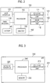
- Fig. 2 is a block diagram of the UE 100.
- the UE 100 includes: antennas 101 and 102; a cellular communication unit 111; a WLAN communication unit 112; a user interface 120; a GNSS (Global Navigation Satellite System) receiver 130; a battery 140; a memory 150; and a processor 160.
- the memory 150 and the processor 160 form a controller.
- the UE 100 may not have the GNSS receiver 130.
- the memory 150 may be integrally formed with the processor 160, and this set (that is, a chipset) may be called a processor 160'.
- the antenna 101 and the cellular communication unit 111 are used for transmitting and receiving a cellular radio signal.
- the cellular communication unit 111 converts a baseband signal output from the processor 160 into the cellular radio signal, and transmits the same from the antenna 101. Further, the cellular communication unit 111 converts the cellular radio signal received by the antenna 101 into the baseband signal, and outputs the same to the processor 160.
- the antenna 102 and the WLAN communication unit 112 are used for transmitting and receiving a WLAN radio signal.
- the WLAN communication unit 112 converts the baseband signal output from the processor 160 into a WLAN radio signal, and transmits the same from the antenna 102. Further, the WLAN communication unit 112 converts the WLAN radio signal received by the antenna 102 into a baseband signal, and outputs the same to the processor 160.
- the user interface 120 is an interface with a user carrying the UE 100, and includes, for example, a display, a microphone, a speaker, and various buttons. Upon receipt of the input from a user, the user interface 120 outputs a signal indicating a content of the input to the processor 160.
- the GNSS receiver 130 receives a GNSS signal in order to obtain location information indicating a geographical location of the UE 100, and outputs the received signal to the processor 160.
- the battery 140 accumulates a power to be supplied to each block of the UE 100.
- the memory 150 stores a program to be executed by the processor 160 and information to be used for a process by the processor 160.
- the processor 160 includes the baseband processor that performs modulation and demodulation, encoding and decoding and the like on the baseband signal and a CPU that performs various processes by executing the program stored in the memory 150.
- the processor 160 may further include a codec that performs encoding and decoding on sound and video signals.
- the processor 160 executes various processes and various communication protocols described later.
- Fig. 3 is a block diagram of the eNB 200.
- the eNB 200 includes an antenna 201, a cellular communication unit 210, a network interface 220, a memory 230, and a processor 240.
- the memory 230 and the processor 240 form a controller.
- the memory 230 may be integrally formed with the processor 240, and this set (that is, a chipset) may be called a processor.
- the antenna 201 and the cellular communication unit 210 are used for transmitting and receiving a cellular radio signal.
- the cellular communication unit 210 converts the baseband signal output from the processor 240 into the cellular radio signal, and transmits the same from the antenna 201. Furthermore, the cellular communication unit 210 converts the cellular radio signal received by the antenna 201 into the baseband signal, and outputs the same to the processor 240.
- the network interface 220 is connected to a backhaul network managed by the operator, for example, and is used for communication with other eNBs 200, the EPC 20, and the AP 300.
- the memory 230 stores a program to be executed by the processor 240 and information to be used for a process by the processor 240.
- the processor 240 includes the baseband processor that performs modulation and demodulation, encoding and decoding and the like on the baseband signal and a CPU that performs various processes by executing the program stored in the memory 230.
- the processor 240 implements various processes and various communication protocols described later.
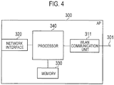
- Fig. 4 is a block diagram of the AP 300. As illustrated in Fig. 4 , the AP 300 includes an antenna 301, a WLAN communication unit 311, a network interface 320, a memory 330, and a processor 340.
- the antenna 301 and the WLAN communication unit 311 are used for transmitting and receiving the WLAN radio signal.
- the WLAN communication unit 311 converts the baseband signal output from the processor 340 into the WLAN radio signal and transmits the same from the antenna 301. Further, the WLAN communication unit 311 converts the WLAN radio signal received by the antenna 301 into the baseband signal and outputs the same to the processor 340.
- the network interface 320 is connected to a backhaul network managed by the operator, for example, and is used for communication with other eNBs 200.
- the memory 330 stores a program to be executed by the processor 340 and information to be used for a process by the processor 340.
- the processor 340 includes the baseband processor that performs modulation and demodulation, encoding and decoding and the like on the baseband signal and a CPU that performs various processes by executing the program stored in the memory 330.
- the processor 340 implements various processes described later.
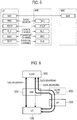
- Fig. 5 is a protocol stack diagram of a radio interface in the LTE system. As illustrated in Fig. 5 , the radio interface protocol is classified into a layer 1 to a layer 3 of an OSI reference model, wherein the layer 1 is a physical (PHY) layer.
- the layer 2 includes a MAC (Media Access Control) layer, an RLC (Radio Link Control) layer, and a PDCP (Packet Data Convergence Protocol) layer.
- the layer 3 includes an RRC (Radio Resource Control) layer.
- the PHY layer performs encoding and decoding, modulation and demodulation, antenna mapping and demapping, and resource mapping and demapping. Between the PHY layer of the UE 100 and the PHY layer of the eNB 200, data is transmitted via the physical channel.
- the MAC layer performs priority control of data, and a retransmission process and the like by hybrid ARQ (HARQ). Between the MAC layer of the UE 100 and the MAC layer of the eNB 200, data is transmitted via a transport channel.
- the MAC layer of the eNB 200 includes a scheduler that selects a transport format (a transport block size, a modulation and coding scheme and the like) of an uplink and a downlink, and an assigned resource block.
- the RLC layer transmits data to an RLC layer of a reception side by using the functions of the MAC layer and the PHY layer. Between the RLC layer of the UE 100 and the RLC layer of the eNB 200, data is transmitted via a logical channel.
- the PDCP layer performs header compression and decompression, and encryption and decryption.
- the RRC layer is defined only in a control plane. Between the RRC layer of the UE 100 and the RRC layer of the eNB 200, a control message (an RRC message) for various types of setting is transmitted.
- the RRC layer controls the logical channel, the transport channel, and the physical channel in response to establishment, re-establishment, and release of a radio bearer.
- RRC connection When there is a connection (RRC connection) between the RRC of the UE 100 and the RRC of the eNB 200, the UE 100 is in a connected state (RRC connected state), otherwise, the UE 100 is in an idle state (RRC idle state).
- a NAS (Non-Access Stratum) layer positioned above the RRC layer performs session management, mobility management and the like.
- the communication system of the embodiment is used in a communication scenario between the eNB 200 and the UE 100 using plural bearers via the AP 300.
- the UE 100 needs to identify a bearer from which the data is received to communicate using the identified bearer.
- the communication system of the embodiment can identify the bearer to be used on the receiver side even when the eNB 200 and the UE 100 communicate via the AP 300 using the bearers.
- the communication system of the embodiment can also be used in uplink communication.
- Fig. 6 illustrates a communication control method of a communication system according to the embodiment.
- the communication system of the embodiment establishes data bearer #1 that passes through the eNB 200 without passing through the AP 300, and data bearers #2 and #3 that passes through both the AP 300 and the eNB 200 between the UE 100 and the S-GW 500 (EPC 20).
- the UE 100 and the eNB 200 directly transmit and receive data using the data bearer #1.
- the UE 100 and the eNB 200 also transmit and receive data with using plural bearers (the data bearers #2 and #3) via the AP 300 (and a WLAN GW 600).
- the UE 100 and the eNB 200 may not directly communicate using the data bearer #1 in the embodiment.
- the communication system may not include the WLAN GW 600.
- the UE 100 has radio connection with the eNB 200 and the AP 300. That is, a radio resource is allocated to the UE 100 from the eNB 200 and the AP 300.
- the eNB 200 maintains RRC connection with the UE 100 that has the radio connection with the eNB 200 and the AP 300.
- the eNB 200 therefore can perform various communication control for the UE 100.
- An RRC layer of the eNB 200 manages the data bearers #1 and #2.
- the communication system of the embodiment enables communication between the UE 100 and the eNB 200 via the AP 300 using the plural bearers.
- the data bearer #2 may be split into two bearers in the eNB 200.
- One bearer of the split bearers terminates in the UE 100 via the AP 300, and the other bearer terminates in the UE 100 without passing through the AP 300.
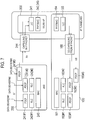
- Fig. 7 illustrates a data transmission system of the embodiment.
- the eNB 200 and the AP 300 transmit and receive data in a PDCP packet that is capsuled into an IP packet in the data bearers #2 and #3.
- the eNB 200 includes a PDCP entity 241#1 for the data bearer #1, a PDCP entity 241#2 for the data bearer #2, a PDCP entity 241#3 for the data bearer #3, an RLC entity 242#1 for the data bearer #1, an RLC entity 242#2 for the data bearer #2, and a MAC entity 243.
- a capsuling entity 244 (first entity) illustrated in Fig. 7 is a function included in the eNB 200 or the WLAN GW 600.
- the AP 300 includes LLC entity 341, MAC LME entity 342, and PHY LME entity 343.
- the UE 100 includes a MAC entity 161, an RLC entity 162#1 for the data bearer #1, an RLC entity 162#2 for the data bearer #2, a PDCP entity 163#1 for the data bearer #1, a PDCP entity 163#2 for the data bearer #2, a PDCP entity 163#3 for the data bearer #3, and a PHY/MAC entity 164, an LLC entity 165, and a de-capsuling entity 166 (second entity) for the WLAN.
- the PDCP entity 241#2 of the eNB 200 distributes data (PDCP packet) that belongs to the data bearer #2 to the AP 300.
- the PDCP entity 241#3 distributes the data (PDCP packet) that belongs to the data bearer #3 to the AP 300.
- the PDCP entity 241#2 may partially distribute the data to the RLC entity 242#2 to transmit the data to the UE 100 via the MAC entity 243. In this case, the UE 100 processes the data that belongs to the data bearer #2 by the MAC entity 161, the RLC entity 162#2, and the PDCP entity 163#2 in this order.
- the data (PDCP packet) distributed to the AP 300 is capsuled into the IP packet by the capsuling entity 244 of the eNB 200 (or the WLAN GW 600) and transferred to the AP 300.
- the capsuling entity 244 capsules the data (PDCP packet) so that the data includes a bearer ID (identification information) to identify the bearers (data bearers #2, #3) used for communication.
- the AP 300 transmits the IP packet to the UE 100 through the LLC entity 341, the MAC LME entity 342, and the PHY LME entity 343.
- the UE 100 processes the data that belongs to the data bearer #2 or #3 by the PHY/MAC entity 164 and the LLC entity 165 in this order, and de-capsules the IP packet by the de-capsuling entity 166 to obtain the PDCP packet.
- the de-capsuling entity 166 informs the PDCP entity 163 of the PDCP packet in accordance with the bearer ID in the IP packet. Specifically, the de-capsuling entity 166 informs the PDCP entity 163#2 of the PDCP packet when the bearer ID indicates the data bearer #2. The de-capsuling entity 166 informs the PDCP entity 163#3 of the PDCP packet when the bearer ID indicates the data bearer #3.
- Such capsuling/de-capsuling of the PDCP packet allows IP tunneling to be set in the WLAN section.
- Security processing such as encryption, authentication, or the like, is performed in the PDCP to realize LTE level security in the communication on the WLAN side by handing over the PDCP packet to the WLAN side.
- the security processing such as encryption, authentication, or the like, may not be performed on the WLAN side.
- the data that belongs to the data bearer #1 is transmitted to the UE 100 through the PDCP entity 241#1, the RLC entity 242#1, and the MAC entity 243.
- the UE 100 processes the data that belongs to the data bearer #1 by the MAC entity 161, the RLC entity 162#1, and the PDCP entity 163#1 in this order.
- the communication system of the embodiment can identify the PDCP entity 163 to which the UE 100 should input data, when the UE 100 has de-capsuled the data for each bearer transmitted through the bearers via the AP 300.
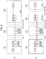
- Fig. 8 illustrates a protocol stack 1 between eNB and UE according to the embodiment.
- the eNB 200 capsules the data (PDCP packet) in the PDCP layer in the IP layer by the capsuling entity 244 to generate the IP packet.
- the header added to the PDCP packet that is, the IP address included in the IP header of the IP packet, is allocated for each PDCP entity 163 of the UE 100.
- the destination IP address of the IP packet is used as the bearer ID.
- the IP address may be the IP address of the UE 100, and the header added to the PDCP packet may include a local IP address used in the WLAN network. In this case, the local IP address is allocated to each bearer.
- the eNB 200 transmits the generated IP packet to the AP 300.
- the AP 300 transmits the received IP packet to the UE 100.
- the de-capsuling entity 166 of the UE 100 de-capsules the received IP packet and causes the PDCP entity 162 corresponding to the IP address to process the PDCP packet.
- the WLAN GW 600 may be disposed between the eNB 200 and the AP 300.
- Fig. 8(b) illustrates a protocol stack in which the WLAN GW 600 disposed between the eNB 200 and the AP 300 includes the capsuling entity 244.
- the examples illustrated in Figs. 8(a) and 8(b) are the same, except for the apparatus including the capsuling entity 244.
- Fig. 9 illustrates a protocol stack 2 between eNB and UE in the embodiment.
- the eNB 200 capsules the data (PDCP packet) of the PDCP layer in an upper layer (e.g., a TCP/UDP layer) of the PDCP layer by the capsuling entity 244.
- the capsuling entity 244 generates data including a port number, which corresponds to the bearer used for communication, in the header of the TCP/UDP layer of the PDCP packet. That is, the port number is used as the bearer ID.
- the port number is correlated with each PDCP entity 163 of the UE 100.
- the eNB 200 capsules the data including the bearer ID in the TCP/UDP header of the PDCP packet in the IP layer, and transmits the IP packet to the AP 300.
- the AP 300 transmits the received IP packet to the UE 100.
- the de-capsuling entity 166 of the UE 100 de-capsules the received IP packet to acquire the port number included in the TCP/UDP header.
- the de-capsuling entity 166 informs the PDCP entity 163 corresponding the acquired port number of the data (PDCP packet) that includes the port number.
- the PDCP entity 163 performs communication using the bearer corresponding to the port number.
- Fig. 10 illustrates data configuration of capsuled data in the embodiment.
- Figs. 10(a) to 10(c) illustrate examples of the PDCP packet with the header including the bearer ID added thereto.
- Fig. 10(a) illustrates the data configuration of data that is capsuled so as to include bearer ID in a Capsule header added to the PDCP packet (PDCP PDU).
- Fig. 10(b) illustrates the data configuration of data that is capsuled so as to include the bearer ID in the TCP/UDP header added to the PDCP packet (PDCP PDU).
- the bearer ID is the port number in Fig. 10(b) .
- the Capsule header may be added to the PDCP packet.
- Fig. 10(c) illustrates the data configuration of data that is capsuled so as to include the bearer ID in an IP header added to the PDCP packet (PDCP PDU).
- the IP address included in the IP header corresponds to the bearer ID in Fig. 10(c) .
- Capsuling the data so that the header of the PDCP packet includes the bearer ID allows the UE 100 to de-capsule the received data to acquire the bearer ID and perform communication using the bearer identified by the acquired bearer ID.
- Fig. 11 is a flowchart illustrating the procedures of generating the PDCP packet in the embodiment.
- the eNB 100 generates the PDCP packet in the example of Fig. 11 .
- step S101 the eNB 200 acquires a PDCP service data unit (SDU).
- SDU PDCP service data unit
- step S102 a sequence number is allocated to the PDCP SDU.
- step S103 it is determined whether the PDCP SDU data is transmitted using a WLAN split bearer. If the PDCP SDU data is not transmitted using the WLAN split bearer (NO at S103), the processing of step S110 is executed. Meanwhile, if the PDCP SDU data is transmitted using the WLAN split bearer (YES at S103), the processing of step S104 is executed.
- step S104 it is determined whether the PDCP SDU is transmitted through the WLAN (AP 300). If the PDCP SDU is not transmitted through the WLAN (NO at S104), the processing of step S110 is executed. Meanwhile, if the PDCP SDU is transmitted through the WLAN (YES at S104), the processing of step S105 is executed.
- Steps S110 to S113 represent the procedures for generating a conventional PDCP packet.
- step S110 the header of the PDCP SDU is compressed (robust header compression (RoHC)).
- RoHC robust header compression
- step S111 security assurance is performed for the PDCP SDU after the compression of the header to prevent data operation by a third party.
- step S112 the PDCP SDU is encrypted.
- step S 113 the PDCP header is added to the PDCP SDU.
- step S104 if it is determined that the PDCP SDU is transmitted via the WLAN, the processing of step S105 is executed.
- step S105 the header of the PDCP SDU is removed and the PDCP SDU is stored.
- the RoHC is not executed when the PDCP SDU is transferred to the AP 300, although the header compression of the PDCP SDU has been ordered.
- step S106 the security assurance is executed for the PDCP SDU after the removal of the header.
- step S107 the PDCP SDU is encrypted.
- step S108 the PDCP header is added to the PDCP SDU.
- the PDCP header includes the bearer ID.
- step S109 the header that has been removed in step S105 is added again to the PDCP SDU after the addition of the PDCP header.
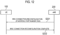
- Fig. 12 illustrates RRC Connection Reconfiguration between eNB and UE of the embodiment. Operations carried out between eNB and UE illustrated in Fig. 12 are executed before the communication using the bearers between the eNB 200 and the UE 100 via the AP 300.
- the eNB 200 transmits an RRC Connection Reconfiguration (which is a signal for changing the connection configuration) including at least one of the IP address, the port number, and an end-point ID of GTP-U tunneling (TEID) to the UE 100.
- the RRC Connection Reconfiguration may include at least one of the IP address, the port number, and the TEID used as the bearer ID. That is, the RRC Connection Reconfiguration includes the bearer ID.
- the UE 100 correlates the bearer ID included in the received RRC Connection Reconfiguration with the PDCP entity 163.
- step S202 the UE 100 transmits an RRC Connection Reconfiguration Complete to the eNB 200.
- the UE 100 may manage a predetermined table that describes correlation between the PDCP entity 163 and the bearer ID.
- Fig. 13 is a sequence diagram illustrating operation procedures of the eNB 200 inquiring information of the UE 100 that communicates with the AP 300 (or the WLAN GW 600) in the embodiment.
- step S301 the eNB 200 and the UE 100 are in an RRC Connected state in which the RRC Connection is established therebetween.
- step S303 the eNB 200 transmits, to the AP 300 (or the WLAN GW 600), a UE inquiry inquiring the IP address of the UE 100 that is used for the communication with the AP 300.
- the UE inquiry includes a UE-ID for identifying the UE 100 with which the RRC Connection has been established in step S301.
- step S304 the AP 300 (or the WLAN GW 600) searches for the IP address of the UE 100 corresponding to the UE-ID included in the UE inquiry.
- step S305 the AP 300 transmits a UE inquiry response including the found IP address to the eNB 200.
- the eNB 200 may directly inquire the UE 100 for the information used for the WLAN communication.
- step S306 subsequent to the step S302, the eNB 200 transmits, to the UE 100, the WLAN information inquiry inquiring information used for the communication between the UE 100 and the AP 300.
- step S308 the UE 100 acquires information used for the communication with the AP 300 when the link is established between the UE 100 and the AP 300.
- the information used for the communication with the AP 300 includes the IP address, an SSID, or the like.
- the communication system of the embodiment described above can identify the bearer, which is to be used on the receiver side, based on the bearer ID that identifies the bearer used in transmission, even when the eNB 200 and the UE 100 communicate using the plural bearers via the AP 300.
- the received data is input to the PDCP entity that is correlated with the identified bearer.
- the eNB 200 and the UE 100 can communicate with each other via the AP 300 using the plural bearers.
- the eNB 200 or the WLAN GW 600 includes the capsuling entity 244, and the UE 100 includes the de-capsuling entity 166.
- the UE 100 may perform a function corresponding to the capsuling entity 244, and the eNB 200 or the WLAN GW 600 may perform a function corresponding to the de-capsuling entity 166.
- the LTE system has been described in the embodiment as an example cellular communication system. However, any cellular communication system other than the LTE system may be used.
- the present invention is useful in the communication field.
Landscapes
- Engineering & Computer Science (AREA)
- Computer Networks & Wireless Communication (AREA)
- Signal Processing (AREA)
- Computer Security & Cryptography (AREA)
- Mobile Radio Communication Systems (AREA)
Abstract
Description
- The present invention relates to a communication system, a user terminal, and a communication control method.
- User terminals capable of cellular communication and wireless local area network (WLAN) communication have become widely used recently. Access points for the WLAN that are managed by operators of the cellular communication network are also increasing. The 3rd Generation Partnership Project (3GPP) has therefore started to study technologies to strengthen interworking between WLAN and cellular radio access network (RAN) (see Non Patent Literature 1).
- Meanwhile, a dual connectivity architecture in which a master eNodeB (MeNB) that is a cellular base station for processing data of plural bearers transfers data of some bearers via another cellular base station called a secondary eNodeB (SeNB) to communicate with user terminals has been studied (see Non Patent Literature 2).
-
- Non Patent Literature 1: 3GPP Technical Report "TR37.834 V12.0.0", December 2013
- Non Patent Literature 2: 3GPP Technical Report, "TR36.842 V12.0.0", January 2014
- A communication system according to an embodiment includes: a user terminal including a communication unit; and a cellular base station configured to communicate with the user terminal via a WLAN access point using a plurality of bearers. The communication unit includes a communication unit configured to communicate with the cellular base station via the WLAN access point using one of the bearers identified in accordance with identification information for uniquely identifying each of the bearers.
- A user terminal according to an embodiment includes a communication unit configured to communicate with a cellular base station via a WLAN access point using a plurality of bearers. The communication unit communicates with the cellular base station via the WLAN access point using one of the bearers identified in accordance with identification information for uniquely identifying each of the bearers.
- A communication control method according to an embodiment includes a step of communicating between a user terminal and a cellular base station via a WLAN access point using a plurality of bearers. The step of communicating includes communicating between the user terminal and the cellular base station via the WLAN access point using one of the bearers identified in accordance with identification information for uniquely identifying each of the bearers.
-
-
Fig. 1 illustrates a communication system according to an embodiment. -
Fig. 2 is a block diagram of a UE according to the embodiment. -
Fig. 3 is a block diagram of an eNB according to the embodiment. -
Fig. 4 is a block diagram of an AP according to the embodiment. -
Fig. 5 illustrates a protocol stack of an LTE radio interface according to the embodiment. -
Fig. 6 illustrates a communication control method of the communication system according to the embodiment. -
Fig. 7 illustrates a data transmission system according to the embodiment. -
Fig. 8 illustrates aprotocol stack 1 between the eNB and the UE according to the embodiment. -
Fig. 9 illustrates aprotocol stack 2 between the eNB and the UE according to the embodiment. -
Fig. 10 illustrates a capsuled data structure according to the embodiment. -
Fig. 11 is a flowchart illustrating a PDCP packet generation procedure according to the embodiment. -
Fig. 12 illustrates an RRC Connection Reconfiguration between eNB and UE according to the embodiment. -
Fig. 13 is a sequence diagram illustrating an operation procedure of the eNB inquiring information of a user terminal that communicates with the AP according to the embodiment. - Hereinafter, an embodiment (present embodiment) in which an LTE system is coordinated with a wireless local area network (WLAN) system will described. The LTE system is a cellular communication system based on 3GPP standards.
-
Fig. 1 illustrates a communication system according to the present embodiment. As illustrated inFig. 1 , the LTE system according to the present embodiment includes UEs (User Equipment) 100, E-UTRAN (Evolved-UMTS Terrestrial Radio Access Network) 10, and EPC (Evolved Packet Core) 20. - The
E-UTRAN 10 corresponds to a cellular RAN. TheEPC 20 corresponds to a core network. TheE-UTRAN 10 and theEPC 20 form a network of the LTE system. - The UE 100 is a mobile communication device, and corresponds to a user terminal. The UE 100 is a terminal (dual terminal) that supports both communication schemes of cellular communication and WLAN communication.
- The
E-UTRAN 10 includes eNBs (evolved Node-Bs) 200. The eNB 200 corresponds to a cellular base station. The eNB 200 manages one or a plurality of cells, and performs radio communication with the UE 100 that establishes a connection with a cell of the eNB 200. The "cell" is used as a term indicating a smallest unit of a radio communication area, and is also used as a term indicating a function of performing radio communication with the UE 100. The eNB 200 has a radio resource management (RRM) function, a routing function of user data, a measurement control function for mobility control and scheduling and the like. - The eNBs 200 are connected mutually via an X2 interface. The eNB 200 is connected to an MME (Mobility Management Entity)/S-GW (Serving-Gateway) 500 included in the
EPC 20 via an S1 interface. - The
EPC 20 includes MMEs/S-GWs 500. The MME performs different types of mobility control and the like for the UE 100, and corresponds to a control station. The S-GW performs transfer control of the user data, and corresponds to a switching station. -
WLAN 30 includes WLAN access point (hereinafter referred to as "AP") 300. The AP 300 is an AP (operator controlled AP) under control of the operator of the LTE network, for example. - The
WLAN 30 is formed by conforming with various IEEE 802.11 standards, for example. The AP 300 communicates with theUE 100 in different frequency bands (WLAN frequency bands) than the cellular frequency bands. The AP 300 is connected to theEPC 20 via routers etc. - The eNB 200 and the AP 300 may be located separately, or the eNB 200 and the AP 300 may be located at the same place (collocated). Alternatively, the eNB 200 and the AP 300 are directly connected via operator's interface.
- Next, the configurations of UE 100, eNB 200, and AP 300 will be described.
-
Fig. 2 is a block diagram of the UE 100. As illustrated inFig. 2 , the UE 100 includes:antennas cellular communication unit 111; aWLAN communication unit 112; auser interface 120; a GNSS (Global Navigation Satellite System)receiver 130; abattery 140; amemory 150; and aprocessor 160. Thememory 150 and theprocessor 160 form a controller. The UE 100 may not have the GNSSreceiver 130. Furthermore, thememory 150 may be integrally formed with theprocessor 160, and this set (that is, a chipset) may be called a processor 160'. - The
antenna 101 and thecellular communication unit 111 are used for transmitting and receiving a cellular radio signal. Thecellular communication unit 111 converts a baseband signal output from theprocessor 160 into the cellular radio signal, and transmits the same from theantenna 101. Further, thecellular communication unit 111 converts the cellular radio signal received by theantenna 101 into the baseband signal, and outputs the same to theprocessor 160. - The
antenna 102 and theWLAN communication unit 112 are used for transmitting and receiving a WLAN radio signal. TheWLAN communication unit 112 converts the baseband signal output from theprocessor 160 into a WLAN radio signal, and transmits the same from theantenna 102. Further, theWLAN communication unit 112 converts the WLAN radio signal received by theantenna 102 into a baseband signal, and outputs the same to theprocessor 160. - The
user interface 120 is an interface with a user carrying theUE 100, and includes, for example, a display, a microphone, a speaker, and various buttons. Upon receipt of the input from a user, theuser interface 120 outputs a signal indicating a content of the input to theprocessor 160. TheGNSS receiver 130 receives a GNSS signal in order to obtain location information indicating a geographical location of theUE 100, and outputs the received signal to theprocessor 160. Thebattery 140 accumulates a power to be supplied to each block of theUE 100. - The
memory 150 stores a program to be executed by theprocessor 160 and information to be used for a process by theprocessor 160. Theprocessor 160 includes the baseband processor that performs modulation and demodulation, encoding and decoding and the like on the baseband signal and a CPU that performs various processes by executing the program stored in thememory 150. Theprocessor 160 may further include a codec that performs encoding and decoding on sound and video signals. Theprocessor 160 executes various processes and various communication protocols described later. -
Fig. 3 is a block diagram of theeNB 200. As illustrated inFig. 3 , theeNB 200 includes anantenna 201, acellular communication unit 210, anetwork interface 220, amemory 230, and aprocessor 240. Thememory 230 and theprocessor 240 form a controller. Furthermore, thememory 230 may be integrally formed with theprocessor 240, and this set (that is, a chipset) may be called a processor. - The
antenna 201 and thecellular communication unit 210 are used for transmitting and receiving a cellular radio signal. Thecellular communication unit 210 converts the baseband signal output from theprocessor 240 into the cellular radio signal, and transmits the same from theantenna 201. Furthermore, thecellular communication unit 210 converts the cellular radio signal received by theantenna 201 into the baseband signal, and outputs the same to theprocessor 240. - The
network interface 220 is connected to a backhaul network managed by the operator, for example, and is used for communication withother eNBs 200, theEPC 20, and theAP 300. - The
memory 230 stores a program to be executed by theprocessor 240 and information to be used for a process by theprocessor 240. Theprocessor 240 includes the baseband processor that performs modulation and demodulation, encoding and decoding and the like on the baseband signal and a CPU that performs various processes by executing the program stored in thememory 230. Theprocessor 240 implements various processes and various communication protocols described later. -
Fig. 4 is a block diagram of theAP 300. As illustrated inFig. 4 , theAP 300 includes anantenna 301, aWLAN communication unit 311, anetwork interface 320, amemory 330, and aprocessor 340. - The
antenna 301 and theWLAN communication unit 311 are used for transmitting and receiving the WLAN radio signal. TheWLAN communication unit 311 converts the baseband signal output from theprocessor 340 into the WLAN radio signal and transmits the same from theantenna 301. Further, theWLAN communication unit 311 converts the WLAN radio signal received by theantenna 301 into the baseband signal and outputs the same to theprocessor 340. - The
network interface 320 is connected to a backhaul network managed by the operator, for example, and is used for communication withother eNBs 200. - The
memory 330 stores a program to be executed by theprocessor 340 and information to be used for a process by theprocessor 340. Theprocessor 340 includes the baseband processor that performs modulation and demodulation, encoding and decoding and the like on the baseband signal and a CPU that performs various processes by executing the program stored in thememory 330. Theprocessor 340 implements various processes described later. -
Fig. 5 is a protocol stack diagram of a radio interface in the LTE system. As illustrated inFig. 5 , the radio interface protocol is classified into alayer 1 to alayer 3 of an OSI reference model, wherein thelayer 1 is a physical (PHY) layer. Thelayer 2 includes a MAC (Media Access Control) layer, an RLC (Radio Link Control) layer, and a PDCP (Packet Data Convergence Protocol) layer. Thelayer 3 includes an RRC (Radio Resource Control) layer. - The PHY layer performs encoding and decoding, modulation and demodulation, antenna mapping and demapping, and resource mapping and demapping. Between the PHY layer of the
UE 100 and the PHY layer of theeNB 200, data is transmitted via the physical channel. - The MAC layer performs priority control of data, and a retransmission process and the like by hybrid ARQ (HARQ). Between the MAC layer of the
UE 100 and the MAC layer of theeNB 200, data is transmitted via a transport channel. The MAC layer of theeNB 200 includes a scheduler that selects a transport format (a transport block size, a modulation and coding scheme and the like) of an uplink and a downlink, and an assigned resource block. - The RLC layer transmits data to an RLC layer of a reception side by using the functions of the MAC layer and the PHY layer. Between the RLC layer of the
UE 100 and the RLC layer of theeNB 200, data is transmitted via a logical channel. - The PDCP layer performs header compression and decompression, and encryption and decryption.
- The RRC layer is defined only in a control plane. Between the RRC layer of the
UE 100 and the RRC layer of theeNB 200, a control message (an RRC message) for various types of setting is transmitted. The RRC layer controls the logical channel, the transport channel, and the physical channel in response to establishment, re-establishment, and release of a radio bearer. When there is a connection (RRC connection) between the RRC of theUE 100 and the RRC of theeNB 200, theUE 100 is in a connected state (RRC connected state), otherwise, theUE 100 is in an idle state (RRC idle state). - A NAS (Non-Access Stratum) layer positioned above the RRC layer performs session management, mobility management and the like.
- An application scenario of a communication system according to an embodiment will be described below. The communication system of the embodiment is used in a communication scenario between the
eNB 200 and theUE 100 using plural bearers via theAP 300. Specifically, in a downlink where theeNB 200 transmits data for each bearer of plural bears from theeNB 200 to theUEs 100, theUE 100 needs to identify a bearer from which the data is received to communicate using the identified bearer. However, when theUE 100 performs WLAN communication with theeNB 200 via theAP 300, theUE 100 which is a receiver of data cannot identify a bearer to be used. To solve this problem, the communication system of the embodiment can identify the bearer to be used on the receiver side even when theeNB 200 and theUE 100 communicate via theAP 300 using the bearers. The communication system of the embodiment can also be used in uplink communication. -
Fig. 6 illustrates a communication control method of a communication system according to the embodiment. - As illustrated in
Fig. 6 , the communication system of the embodiment establishesdata bearer # 1 that passes through theeNB 200 without passing through theAP 300, anddata bearers # 2 and #3 that passes through both theAP 300 and theeNB 200 between theUE 100 and the S-GW 500 (EPC 20). In other words, theUE 100 and theeNB 200 directly transmit and receive data using thedata bearer # 1. TheUE 100 and theeNB 200 also transmit and receive data with using plural bearers (thedata bearers # 2 and #3) via the AP 300 (and a WLAN GW 600). TheUE 100 and theeNB 200 may not directly communicate using thedata bearer # 1 in the embodiment. The communication system may not include theWLAN GW 600. - The
UE 100 has radio connection with theeNB 200 and theAP 300. That is, a radio resource is allocated to theUE 100 from theeNB 200 and theAP 300. - The
eNB 200 maintains RRC connection with theUE 100 that has the radio connection with theeNB 200 and theAP 300. TheeNB 200 therefore can perform various communication control for theUE 100. An RRC layer of theeNB 200 manages thedata bearers # 1 and #2. - The communication system of the embodiment enables communication between the
UE 100 and theeNB 200 via theAP 300 using the plural bearers. - As illustrated in
Fig. 6 , thedata bearer # 2 may be split into two bearers in theeNB 200. One bearer of the split bearers terminates in theUE 100 via theAP 300, and the other bearer terminates in theUE 100 without passing through theAP 300. -
Fig. 7 illustrates a data transmission system of the embodiment. In the embodiment, theeNB 200 and theAP 300 transmit and receive data in a PDCP packet that is capsuled into an IP packet in thedata bearers # 2 and #3. - As illustrated in
Fig. 7 , theeNB 200 includes aPDCP entity 241#1 for thedata bearer # 1, aPDCP entity 241#2 for thedata bearer # 2, aPDCP entity 241#3 for thedata bearer # 3, anRLC entity 242#1 for thedata bearer # 1, anRLC entity 242#2 for thedata bearer # 2, and aMAC entity 243. A capsuling entity 244 (first entity) illustrated inFig. 7 is a function included in theeNB 200 or theWLAN GW 600. - The
AP 300 includesLLC entity 341, MAC LME entity 342, and PHY LME entity 343. - The
UE 100 includes aMAC entity 161, anRLC entity 162#1 for thedata bearer # 1, anRLC entity 162#2 for thedata bearer # 2, aPDCP entity 163#1 for thedata bearer # 1, aPDCP entity 163#2 for thedata bearer # 2, aPDCP entity 163#3 for thedata bearer # 3, and a PHY/MAC entity 164, anLLC entity 165, and a de-capsuling entity 166 (second entity) for the WLAN. - The
PDCP entity 241#2 of theeNB 200 distributes data (PDCP packet) that belongs to thedata bearer # 2 to theAP 300. ThePDCP entity 241#3 distributes the data (PDCP packet) that belongs to thedata bearer # 3 to theAP 300. ThePDCP entity 241#2 may partially distribute the data to theRLC entity 242#2 to transmit the data to theUE 100 via theMAC entity 243. In this case, theUE 100 processes the data that belongs to thedata bearer # 2 by theMAC entity 161, theRLC entity 162#2, and thePDCP entity 163#2 in this order. - The data (PDCP packet) distributed to the
AP 300 is capsuled into the IP packet by thecapsuling entity 244 of the eNB 200 (or the WLAN GW 600) and transferred to theAP 300. Thecapsuling entity 244 capsules the data (PDCP packet) so that the data includes a bearer ID (identification information) to identify the bearers (data bearers # 2, #3) used for communication. TheAP 300 transmits the IP packet to theUE 100 through theLLC entity 341, the MAC LME entity 342, and the PHY LME entity 343. - The
UE 100 processes the data that belongs to thedata bearer # 2 or #3 by the PHY/MAC entity 164 and theLLC entity 165 in this order, and de-capsules the IP packet by thede-capsuling entity 166 to obtain the PDCP packet. Thede-capsuling entity 166 informs thePDCP entity 163 of the PDCP packet in accordance with the bearer ID in the IP packet. Specifically, thede-capsuling entity 166 informs thePDCP entity 163#2 of the PDCP packet when the bearer ID indicates thedata bearer # 2. Thede-capsuling entity 166 informs thePDCP entity 163#3 of the PDCP packet when the bearer ID indicates thedata bearer # 3. Such capsuling/de-capsuling of the PDCP packet allows IP tunneling to be set in the WLAN section. Security processing, such as encryption, authentication, or the like, is performed in the PDCP to realize LTE level security in the communication on the WLAN side by handing over the PDCP packet to the WLAN side. The security processing, such as encryption, authentication, or the like, may not be performed on the WLAN side. - Meanwhile, the data that belongs to the
data bearer # 1 is transmitted to theUE 100 through thePDCP entity 241#1, theRLC entity 242#1, and theMAC entity 243. TheUE 100 processes the data that belongs to thedata bearer # 1 by theMAC entity 161, theRLC entity 162#1, and thePDCP entity 163#1 in this order. - Thus, the communication system of the embodiment can identify the
PDCP entity 163 to which theUE 100 should input data, when theUE 100 has de-capsuled the data for each bearer transmitted through the bearers via theAP 300. -
Fig. 8 illustrates aprotocol stack 1 between eNB and UE according to the embodiment. - As illustrated in
Fig. 8 (a) , theeNB 200 capsules the data (PDCP packet) in the PDCP layer in the IP layer by thecapsuling entity 244 to generate the IP packet. In the embodiment, the header added to the PDCP packet, that is, the IP address included in the IP header of the IP packet, is allocated for eachPDCP entity 163 of theUE 100. In other words, the destination IP address of the IP packet is used as the bearer ID. The IP address may be the IP address of theUE 100, and the header added to the PDCP packet may include a local IP address used in the WLAN network. In this case, the local IP address is allocated to each bearer. TheeNB 200 transmits the generated IP packet to theAP 300. TheAP 300 transmits the received IP packet to theUE 100. Thede-capsuling entity 166 of theUE 100 de-capsules the received IP packet and causes thePDCP entity 162 corresponding to the IP address to process the PDCP packet. InFig. 8 (a) , theWLAN GW 600 may be disposed between theeNB 200 and theAP 300. -
Fig. 8(b) illustrates a protocol stack in which theWLAN GW 600 disposed between theeNB 200 and theAP 300 includes thecapsuling entity 244. The examples illustrated inFigs. 8(a) and 8(b) are the same, except for the apparatus including thecapsuling entity 244. -
Fig. 9 illustrates aprotocol stack 2 between eNB and UE in the embodiment. - As illustrated in
Fig. 9 , theeNB 200 capsules the data (PDCP packet) of the PDCP layer in an upper layer (e.g., a TCP/UDP layer) of the PDCP layer by thecapsuling entity 244. In this case, thecapsuling entity 244 generates data including a port number, which corresponds to the bearer used for communication, in the header of the TCP/UDP layer of the PDCP packet. That is, the port number is used as the bearer ID. The port number is correlated with eachPDCP entity 163 of theUE 100. Subsequently, theeNB 200 capsules the data including the bearer ID in the TCP/UDP header of the PDCP packet in the IP layer, and transmits the IP packet to theAP 300. TheAP 300 transmits the received IP packet to theUE 100. Thede-capsuling entity 166 of theUE 100 de-capsules the received IP packet to acquire the port number included in the TCP/UDP header. Thede-capsuling entity 166 informs thePDCP entity 163 corresponding the acquired port number of the data (PDCP packet) that includes the port number. ThePDCP entity 163 performs communication using the bearer corresponding to the port number. -
Fig. 10 illustrates data configuration of capsuled data in the embodiment.Figs. 10(a) to 10(c) illustrate examples of the PDCP packet with the header including the bearer ID added thereto. -
Fig. 10(a) illustrates the data configuration of data that is capsuled so as to include bearer ID in a Capsule header added to the PDCP packet (PDCP PDU). -
Fig. 10(b) illustrates the data configuration of data that is capsuled so as to include the bearer ID in the TCP/UDP header added to the PDCP packet (PDCP PDU). The bearer ID is the port number inFig. 10(b) . The Capsule header may be added to the PDCP packet. -
Fig. 10(c) illustrates the data configuration of data that is capsuled so as to include the bearer ID in an IP header added to the PDCP packet (PDCP PDU). The IP address included in the IP header corresponds to the bearer ID inFig. 10(c) . - Capsuling the data so that the header of the PDCP packet includes the bearer ID, as illustrated in
Figs. 10(a) to 10(c) , allows theUE 100 to de-capsule the received data to acquire the bearer ID and perform communication using the bearer identified by the acquired bearer ID. -
Fig. 11 is a flowchart illustrating the procedures of generating the PDCP packet in the embodiment. TheeNB 100 generates the PDCP packet in the example ofFig. 11 . - In step S101, the
eNB 200 acquires a PDCP service data unit (SDU). - In step S102, a sequence number is allocated to the PDCP SDU.
- In step S103, it is determined whether the PDCP SDU data is transmitted using a WLAN split bearer. If the PDCP SDU data is not transmitted using the WLAN split bearer (NO at S103), the processing of step S110 is executed. Meanwhile, if the PDCP SDU data is transmitted using the WLAN split bearer (YES at S103), the processing of step S104 is executed.
- In S104, it is determined whether the PDCP SDU is transmitted through the WLAN (AP 300). If the PDCP SDU is not transmitted through the WLAN (NO at S104), the processing of step S110 is executed. Meanwhile, if the PDCP SDU is transmitted through the WLAN (YES at S104), the processing of step S105 is executed.
- Steps S110 to S113 represent the procedures for generating a conventional PDCP packet.
- In step S110, the header of the PDCP SDU is compressed (robust header compression (RoHC)).
- In step S111, security assurance is performed for the PDCP SDU after the compression of the header to prevent data operation by a third party.
- In step S112, the PDCP SDU is encrypted.
- In step S 113, the PDCP header is added to the PDCP SDU.
- Meanwhile, in step S104, if it is determined that the PDCP SDU is transmitted via the WLAN, the processing of step S105 is executed.
- In step S105, the header of the PDCP SDU is removed and the PDCP SDU is stored. The RoHC is not executed when the PDCP SDU is transferred to the
AP 300, although the header compression of the PDCP SDU has been ordered. - In step S106, the security assurance is executed for the PDCP SDU after the removal of the header.
- In step S107, the PDCP SDU is encrypted.
- In step S108, the PDCP header is added to the PDCP SDU. The PDCP header includes the bearer ID.
- In step S109, the header that has been removed in step S105 is added again to the PDCP SDU after the addition of the PDCP header.
-
Fig. 12 illustrates RRC Connection Reconfiguration between eNB and UE of the embodiment. Operations carried out between eNB and UE illustrated inFig. 12 are executed before the communication using the bearers between theeNB 200 and theUE 100 via theAP 300. - In step S201, the
eNB 200 transmits an RRC Connection Reconfiguration (which is a signal for changing the connection configuration) including at least one of the IP address, the port number, and an end-point ID of GTP-U tunneling (TEID) to theUE 100. The RRC Connection Reconfiguration may include at least one of the IP address, the port number, and the TEID used as the bearer ID. That is, the RRC Connection Reconfiguration includes the bearer ID. - If the port number is used as the bearer ID, the port number may be compressed to the largest number of bearers capable of setting port numbers thereon. For example, if the largest number of bearers is 8, the port number is compressed to 3-bit information. In one example of compression, the port number = 65536 (16 bits) - bearer ID. In another example of compression, the port number = 65528 + bearer ID. The numbers may be randomly selected other than the illustrated numbers "65536" and "65528".
- The
UE 100 correlates the bearer ID included in the received RRC Connection Reconfiguration with thePDCP entity 163. - In step S202, the
UE 100 transmits an RRC Connection Reconfiguration Complete to theeNB 200. - Thus, the
UE 100 can manage thePDCP entity 163 of theUE 100 and the bearer ID by correlating them with each other. When theUE 100 receives data transmitted from theeNB 200 via theAP 300, theUE 100 can process the PDCP packet by thePDCP entity 163 that corresponds to the bearer ID included in the data. - Alternatively, the
UE 100 may manage a predetermined table that describes correlation between thePDCP entity 163 and the bearer ID. -
Fig. 13 is a sequence diagram illustrating operation procedures of theeNB 200 inquiring information of theUE 100 that communicates with the AP 300 (or the WLAN GW 600) in the embodiment. - In step S301, the
eNB 200 and theUE 100 are in an RRC Connected state in which the RRC Connection is established therebetween. - In step S302, the link is established between the
AP 300 and theUE 100. - In step S303, the
eNB 200 transmits, to the AP 300 (or the WLAN GW 600), a UE inquiry inquiring the IP address of theUE 100 that is used for the communication with theAP 300. The UE inquiry includes a UE-ID for identifying theUE 100 with which the RRC Connection has been established in step S301. - In step S304, the AP 300 (or the WLAN GW 600) searches for the IP address of the
UE 100 corresponding to the UE-ID included in the UE inquiry. - In step S305, the
AP 300 transmits a UE inquiry response including the found IP address to theeNB 200. - Alternatively, the
eNB 200 may directly inquire theUE 100 for the information used for the WLAN communication. - In step S306 subsequent to the step S302, the
eNB 200 transmits, to theUE 100, the WLAN information inquiry inquiring information used for the communication between theUE 100 and theAP 300. - In step S308, the
UE 100 acquires information used for the communication with theAP 300 when the link is established between theUE 100 and theAP 300. The information used for the communication with theAP 300 includes the IP address, an SSID, or the like. - In step S309, the
UE 100 transmits a WLAN information inquiry response that includes the information acquired in step S308 to theeNB 200. - The above procedures allow the
eNB 200 to acquire information necessary for the communication with theUE 100 via theAP 300. - The communication system of the embodiment described above can identify the bearer, which is to be used on the receiver side, based on the bearer ID that identifies the bearer used in transmission, even when the
eNB 200 and theUE 100 communicate using the plural bearers via theAP 300. On the receiver side, the received data is input to the PDCP entity that is correlated with the identified bearer. Thus, theeNB 200 and theUE 100 can communicate with each other via theAP 300 using the plural bearers. - In the embodiment described above, the
eNB 200 or theWLAN GW 600 includes thecapsuling entity 244, and theUE 100 includes thede-capsuling entity 166. In the uplink communication, for example, theUE 100 may perform a function corresponding to thecapsuling entity 244, and theeNB 200 or theWLAN GW 600 may perform a function corresponding to thede-capsuling entity 166. - The LTE system has been described in the embodiment as an example cellular communication system. However, any cellular communication system other than the LTE system may be used.
- The entire contents of Japanese Patent Application No.
2014-097180 (filed on May 8, 2014 - The present invention is useful in the communication field.
Claims (10)
- A communication system comprising:a user terminal including a communication unit; anda cellular base station configured to communicate with the user terminal via a WLAN access point using a plurality of bearers, whereinthe communication unit includes a communication unit configured to communicate with the cellular base station via the WLAN access point using one of the bearers identified in accordance with identification information for uniquely identifying each of the bearers.
- The communication system according to claim 1, wherein
the identification information is transmitted to the user terminal via the WLAN access point. - The communication system according to claim 1, wherein
the identification information is an IP address or a port number. - The communication system according to claim 1, wherein
the user terminal and the cellular base station include a plurality of PDCP entities individually correlated to each of the bearers,
the cellular base station has a first entity, and
the first entity is configured to generate data that includes, in a PDCP packet processed by a PDCP entity of the PDCP entities included in the cellular base station, the identification information corresponding to the PDCP entity. - The communication system according to claim 1 further comprising:a gateway apparatus connected to the cellular base station and configured to accommodate the WLAN, whereinthe user terminal and the cellular base station include a plurality of PDCP entities individually correlated to each of the bearers,the gateway apparatus has a first entity, andthe first entity is configured to generate data that includes, in a PDCP packet processed by a PDCP entity of the PDCP entities included in the cellular base station, the identification information corresponding to the PDCP entity.
- The communication system according to claim 4, wherein
the user terminal further includes a second entity,
the first entity is further configured to capsule the PDCP packet and generate the data including the identification information in a header added to the PDCP packet, and
the second entity is configured to inform the PDCP entity included in the user terminal of the identification information acquired from the data. - The communication system according to claim 4, wherein
the first entity is further configured to encrypt data excluding a PDCP header included in the PDCP packet. - The communication system according to claim 4, wherein
the cellular base station further includes a transmitter,
the user terminal further includes a PDCP entity management unit,
the transmitter is configured to transmit a signal for changing connection configuration to the user terminal, the signal including the identification information correlated to the PDCP entity included in the cellular base station,
the PDCP entity management unit is configured to correlate the identification information included in the signal for changing connection configuration with the PDCP entity included in the user terminal, and
the communication unit is further configured to perform communication subsequent to the correlating between the identification information included in the signal for changing connection configuration and the PDCP entity. - A user terminal comprising:a communication unit configured to communicate with a cellular base station via a WLAN access point using a plurality of bearers,the communication unit communicating with the cellular base station via the WLAN access point using one of the bearers identified in accordance with identification information for uniquely identifying each of the bearers.
- A communication control method comprising:a step of communicating between a user terminal and a cellular base station via a WLAN access point using a plurality of bearers,the step of communicating including communicating between the user terminal and the cellular base station via the WLAN access point using one of the bearers identified in accordance with identification information for uniquely identifying each of the bearers.
Applications Claiming Priority (2)
| Application Number | Priority Date | Filing Date | Title |
|---|---|---|---|
| JP2014097180 | 2014-05-08 | ||
| PCT/JP2015/063374 WO2015170764A1 (en) | 2014-05-08 | 2015-05-08 | Communication system, user terminal and communication control method |
Publications (3)
| Publication Number | Publication Date |
|---|---|
| EP3142391A1 true EP3142391A1 (en) | 2017-03-15 |
| EP3142391A4 EP3142391A4 (en) | 2017-12-27 |
| EP3142391B1 EP3142391B1 (en) | 2019-08-21 |
Family
ID=54392612
Family Applications (1)
| Application Number | Title | Priority Date | Filing Date |
|---|---|---|---|
| EP15789196.1A Active EP3142391B1 (en) | 2014-05-08 | 2015-05-08 | Communication system, user terminal and communication control method |
Country Status (4)
| Country | Link |
|---|---|
| US (1) | US9832683B2 (en) |
| EP (1) | EP3142391B1 (en) |
| JP (2) | JP6084754B2 (en) |
| WO (1) | WO2015170764A1 (en) |
Cited By (1)
| Publication number | Priority date | Publication date | Assignee | Title |
|---|---|---|---|---|
| TWI756363B (en) * | 2017-03-22 | 2022-03-01 | 美商高通公司 | Radio resource control (rrc) entity selection for rrc messages |
Families Citing this family (9)
| Publication number | Priority date | Publication date | Assignee | Title |
|---|---|---|---|---|
| EP3171651B1 (en) | 2014-08-12 | 2020-12-16 | Huawei Technologies Co., Ltd. | Downlink distribution/convergence method, uplink distribution/convergence method and device |
| GB2534865A (en) * | 2015-01-30 | 2016-08-10 | Nec Corp | Communication system |
| US10869344B2 (en) | 2015-03-19 | 2020-12-15 | Acer Incorporated | Method of radio bearer transmission in dual connectivity |
| US10412652B2 (en) * | 2015-04-10 | 2019-09-10 | Samsung Electronics Co., Ltd. | Apparatus and method for routing data packet to user equipment in LTE-WLAN aggregation system |
| CN108702650A (en) * | 2015-08-06 | 2018-10-23 | 优科无线公司 | Establish LWA-WLAN communications |
| WO2017099165A1 (en) * | 2015-12-11 | 2017-06-15 | 日本電気株式会社 | Radio base station, edge server, and methods thereof |
| JP6777156B2 (en) * | 2016-09-29 | 2020-10-28 | 日本電気株式会社 | Base stations, gateways, methods, programs and recording media |
| US10237784B2 (en) | 2017-03-24 | 2019-03-19 | Motorola Mobility Llc | Split bearer packet data converge protocol protocol data unit routing |
| KR102556490B1 (en) * | 2018-06-04 | 2023-07-17 | 삼성전자주식회사 | Apparatus and method for accelerating encryption and decrpytion processing in wireless communication system |
Family Cites Families (17)
| Publication number | Priority date | Publication date | Assignee | Title |
|---|---|---|---|---|
| JP4828051B2 (en) * | 2001-07-23 | 2011-11-30 | 京セラ株式会社 | Wireless communication system and method, computer program, and wireless communication terminal |
| CN102026398B (en) * | 2009-09-15 | 2013-02-13 | 普天信息技术研究院有限公司 | Method and device for realizing packet data convergence protocol of LTE relay system |
| US9392515B2 (en) * | 2010-02-12 | 2016-07-12 | Interdigital Technology Corporation | Data split between multiple sites |
| WO2012148443A1 (en) * | 2011-04-29 | 2012-11-01 | Intel Corporation | System and method of rank adaptation in mimo communication system |
| CN105592500A (en) * | 2011-05-27 | 2016-05-18 | 上海华为技术有限公司 | Data flow transmission method and user equipment |
| JP5944004B2 (en) * | 2011-10-03 | 2016-07-05 | インテル・コーポレーション | Device-to-device communication (D2D communication) mechanism |
| WO2013052805A1 (en) * | 2011-10-07 | 2013-04-11 | Interdigital Patent Holdings Inc. | Method and apparatus for integrating different radio access technologies using carrier aggregation |
| US9883441B2 (en) * | 2011-11-10 | 2018-01-30 | Nokia Technologies Oy | Method and apparatus to route packet flows over two transport radios |
| WO2013141572A1 (en) * | 2012-03-19 | 2013-09-26 | 삼성전자 주식회사 | Communication method and apparatus using wireless lan access point |
| CN103582011A (en) * | 2012-07-26 | 2014-02-12 | 中兴通讯股份有限公司 | A system, user equipment and method for multi-network joint transmission |
| EP2723134B1 (en) * | 2012-10-18 | 2014-11-26 | Fujitsu Limited | Wireless communication in Multi-RAT System |
| CN104396302B (en) * | 2013-01-18 | 2018-10-30 | 华为技术有限公司 | Method, base station and the user equipment of transmission data |
| WO2015030845A1 (en) * | 2013-08-30 | 2015-03-05 | Intel IP Corporation | Measurement triggers for customer care in a wireless network |
| US9585048B2 (en) * | 2013-10-30 | 2017-02-28 | Qualcomm Incorporated | Techniques for aggregating data from WWAN and WLAN |
| US9596707B2 (en) * | 2014-03-13 | 2017-03-14 | Intel Corporation | Bearer mobility and splitting in a radio access network-based, 3rd generation partnership project network having an integrated wireless local area network |
| US10117287B2 (en) * | 2014-08-26 | 2018-10-30 | Nokia Of America Corporation | Method and apparatus for improved dual connectivity |
| US10567554B2 (en) * | 2015-05-15 | 2020-02-18 | Hfi Innovation Inc. | Routing solutions for LTE-WLAN aggregation |
-
2015
- 2015-05-08 JP JP2016518235A patent/JP6084754B2/en active Active
- 2015-05-08 EP EP15789196.1A patent/EP3142391B1/en active Active
- 2015-05-08 WO PCT/JP2015/063374 patent/WO2015170764A1/en not_active Ceased
-
2016
- 2016-07-28 US US15/222,537 patent/US9832683B2/en active Active
-
2017
- 2017-01-25 JP JP2017011111A patent/JP6151871B2/en active Active
Cited By (1)
| Publication number | Priority date | Publication date | Assignee | Title |
|---|---|---|---|---|
| TWI756363B (en) * | 2017-03-22 | 2022-03-01 | 美商高通公司 | Radio resource control (rrc) entity selection for rrc messages |
Also Published As
| Publication number | Publication date |
|---|---|
| EP3142391A4 (en) | 2017-12-27 |
| JP6084754B2 (en) | 2017-02-22 |
| JPWO2015170764A1 (en) | 2017-04-20 |
| EP3142391B1 (en) | 2019-08-21 |
| JP2017112625A (en) | 2017-06-22 |
| US20160337958A1 (en) | 2016-11-17 |
| WO2015170764A1 (en) | 2015-11-12 |
| JP6151871B2 (en) | 2017-06-21 |
| US9832683B2 (en) | 2017-11-28 |
Similar Documents
| Publication | Publication Date | Title |
|---|---|---|
| US9832683B2 (en) | Communication system, user terminal, and communication control method utilizing plural bearers for cellular and WLAN communication | |
| US9832699B2 (en) | Communication control method, user terminal, cellular base station, and access point | |
| JP6449413B2 (en) | Communication system, user terminal, processor, and cellular base station | |
| US20170070902A1 (en) | Mobile communication system, base station, and user terminal | |
| JPWO2015076345A1 (en) | Communication control method, user terminal, and processor | |
| US10313886B2 (en) | Communication control method and base station | |
| US20160278071A1 (en) | Radio communication apparatus, processor, and communication control method | |
| EP3110194A1 (en) | Moving body communication system, specific base station, and user terminal | |
| JP6515083B2 (en) | User terminal and communication control method | |
| US20160249215A1 (en) | Communication control method, authentication server, and user terminal | |
| JP6563454B2 (en) | Base station, processor, and communication control method | |
| JP2016136755A (en) | Radio communication device, processor, and communication control method |
Legal Events
| Date | Code | Title | Description |
|---|---|---|---|
| STAA | Information on the status of an ep patent application or granted ep patent |
Free format text: STATUS: THE INTERNATIONAL PUBLICATION HAS BEEN MADE |
|
| PUAI | Public reference made under article 153(3) epc to a published international application that has entered the european phase |
Free format text: ORIGINAL CODE: 0009012 |
|
| STAA | Information on the status of an ep patent application or granted ep patent |
Free format text: STATUS: REQUEST FOR EXAMINATION WAS MADE |
|
| 17P | Request for examination filed |
Effective date: 20161107 |
|
| AK | Designated contracting states |
Kind code of ref document: A1 Designated state(s): AL AT BE BG CH CY CZ DE DK EE ES FI FR GB GR HR HU IE IS IT LI LT LU LV MC MK MT NL NO PL PT RO RS SE SI SK SM TR |
|
| AX | Request for extension of the european patent |
Extension state: BA ME |
|
| DAV | Request for validation of the european patent (deleted) | ||
| DAX | Request for extension of the european patent (deleted) | ||
| A4 | Supplementary search report drawn up and despatched |
Effective date: 20171127 |
|
| RIC1 | Information provided on ipc code assigned before grant |
Ipc: H04W 28/08 20090101AFI20171121BHEP Ipc: H04W 28/10 20090101ALI20171121BHEP |
|
| RIC1 | Information provided on ipc code assigned before grant |
Ipc: H04W 28/08 20090101AFI20171201BHEP Ipc: H04W 28/10 20090101ALI20171201BHEP |
|
| STAA | Information on the status of an ep patent application or granted ep patent |
Free format text: STATUS: EXAMINATION IS IN PROGRESS |
|
| 17Q | First examination report despatched |
Effective date: 20180831 |
|
| REG | Reference to a national code |
Ref country code: DE Ref legal event code: R079 Ref document number: 602015036352 Country of ref document: DE Free format text: PREVIOUS MAIN CLASS: H04W0004000000 Ipc: H04W0028080000 |
|
| GRAP | Despatch of communication of intention to grant a patent |
Free format text: ORIGINAL CODE: EPIDOSNIGR1 |
|
| STAA | Information on the status of an ep patent application or granted ep patent |
Free format text: STATUS: GRANT OF PATENT IS INTENDED |
|
| RIC1 | Information provided on ipc code assigned before grant |
Ipc: H04W 28/12 20090101ALN20190222BHEP Ipc: H04L 29/06 20060101ALI20190222BHEP Ipc: H04W 76/15 20180101ALI20190222BHEP Ipc: H04W 28/08 20090101AFI20190222BHEP |
|
| INTG | Intention to grant announced |
Effective date: 20190311 |
|
| GRAS | Grant fee paid |
Free format text: ORIGINAL CODE: EPIDOSNIGR3 |
|
| GRAA | (expected) grant |
Free format text: ORIGINAL CODE: 0009210 |
|
| STAA | Information on the status of an ep patent application or granted ep patent |
Free format text: STATUS: THE PATENT HAS BEEN GRANTED |
|
| AK | Designated contracting states |
Kind code of ref document: B1 Designated state(s): AL AT BE BG CH CY CZ DE DK EE ES FI FR GB GR HR HU IE IS IT LI LT LU LV MC MK MT NL NO PL PT RO RS SE SI SK SM TR |
|
| REG | Reference to a national code |
Ref country code: GB Ref legal event code: FG4D |
|
| REG | Reference to a national code |
Ref country code: CH Ref legal event code: EP |
|
| REG | Reference to a national code |
Ref country code: DE Ref legal event code: R096 Ref document number: 602015036352 Country of ref document: DE |
|
| REG | Reference to a national code |
Ref country code: AT Ref legal event code: REF Ref document number: 1171155 Country of ref document: AT Kind code of ref document: T Effective date: 20190915 |
|
| REG | Reference to a national code |
Ref country code: IE Ref legal event code: FG4D |
|
| REG | Reference to a national code |
Ref country code: LT Ref legal event code: MG4D |
|
| REG | Reference to a national code |
Ref country code: NL Ref legal event code: MP Effective date: 20190821 |
|
| PG25 | Lapsed in a contracting state [announced via postgrant information from national office to epo] |
Ref country code: PT Free format text: LAPSE BECAUSE OF FAILURE TO SUBMIT A TRANSLATION OF THE DESCRIPTION OR TO PAY THE FEE WITHIN THE PRESCRIBED TIME-LIMIT Effective date: 20191223 Ref country code: NO Free format text: LAPSE BECAUSE OF FAILURE TO SUBMIT A TRANSLATION OF THE DESCRIPTION OR TO PAY THE FEE WITHIN THE PRESCRIBED TIME-LIMIT Effective date: 20191121 Ref country code: BG Free format text: LAPSE BECAUSE OF FAILURE TO SUBMIT A TRANSLATION OF THE DESCRIPTION OR TO PAY THE FEE WITHIN THE PRESCRIBED TIME-LIMIT Effective date: 20191121 Ref country code: NL Free format text: LAPSE BECAUSE OF FAILURE TO SUBMIT A TRANSLATION OF THE DESCRIPTION OR TO PAY THE FEE WITHIN THE PRESCRIBED TIME-LIMIT Effective date: 20190821 Ref country code: LT Free format text: LAPSE BECAUSE OF FAILURE TO SUBMIT A TRANSLATION OF THE DESCRIPTION OR TO PAY THE FEE WITHIN THE PRESCRIBED TIME-LIMIT Effective date: 20190821 Ref country code: HR Free format text: LAPSE BECAUSE OF FAILURE TO SUBMIT A TRANSLATION OF THE DESCRIPTION OR TO PAY THE FEE WITHIN THE PRESCRIBED TIME-LIMIT Effective date: 20190821 Ref country code: FI Free format text: LAPSE BECAUSE OF FAILURE TO SUBMIT A TRANSLATION OF THE DESCRIPTION OR TO PAY THE FEE WITHIN THE PRESCRIBED TIME-LIMIT Effective date: 20190821 Ref country code: SE Free format text: LAPSE BECAUSE OF FAILURE TO SUBMIT A TRANSLATION OF THE DESCRIPTION OR TO PAY THE FEE WITHIN THE PRESCRIBED TIME-LIMIT Effective date: 20190821 |
|
| PG25 | Lapsed in a contracting state [announced via postgrant information from national office to epo] |
Ref country code: AL Free format text: LAPSE BECAUSE OF FAILURE TO SUBMIT A TRANSLATION OF THE DESCRIPTION OR TO PAY THE FEE WITHIN THE PRESCRIBED TIME-LIMIT Effective date: 20190821 Ref country code: GR Free format text: LAPSE BECAUSE OF FAILURE TO SUBMIT A TRANSLATION OF THE DESCRIPTION OR TO PAY THE FEE WITHIN THE PRESCRIBED TIME-LIMIT Effective date: 20191122 Ref country code: IS Free format text: LAPSE BECAUSE OF FAILURE TO SUBMIT A TRANSLATION OF THE DESCRIPTION OR TO PAY THE FEE WITHIN THE PRESCRIBED TIME-LIMIT Effective date: 20191221 Ref country code: RS Free format text: LAPSE BECAUSE OF FAILURE TO SUBMIT A TRANSLATION OF THE DESCRIPTION OR TO PAY THE FEE WITHIN THE PRESCRIBED TIME-LIMIT Effective date: 20190821 Ref country code: LV Free format text: LAPSE BECAUSE OF FAILURE TO SUBMIT A TRANSLATION OF THE DESCRIPTION OR TO PAY THE FEE WITHIN THE PRESCRIBED TIME-LIMIT Effective date: 20190821 Ref country code: ES Free format text: LAPSE BECAUSE OF FAILURE TO SUBMIT A TRANSLATION OF THE DESCRIPTION OR TO PAY THE FEE WITHIN THE PRESCRIBED TIME-LIMIT Effective date: 20190821 |
|
| REG | Reference to a national code |
Ref country code: AT Ref legal event code: MK05 Ref document number: 1171155 Country of ref document: AT Kind code of ref document: T Effective date: 20190821 |
|
| PG25 | Lapsed in a contracting state [announced via postgrant information from national office to epo] |
Ref country code: TR Free format text: LAPSE BECAUSE OF FAILURE TO SUBMIT A TRANSLATION OF THE DESCRIPTION OR TO PAY THE FEE WITHIN THE PRESCRIBED TIME-LIMIT Effective date: 20190821 |
|
| PG25 | Lapsed in a contracting state [announced via postgrant information from national office to epo] |
Ref country code: DK Free format text: LAPSE BECAUSE OF FAILURE TO SUBMIT A TRANSLATION OF THE DESCRIPTION OR TO PAY THE FEE WITHIN THE PRESCRIBED TIME-LIMIT Effective date: 20190821 Ref country code: AT Free format text: LAPSE BECAUSE OF FAILURE TO SUBMIT A TRANSLATION OF THE DESCRIPTION OR TO PAY THE FEE WITHIN THE PRESCRIBED TIME-LIMIT Effective date: 20190821 Ref country code: PL Free format text: LAPSE BECAUSE OF FAILURE TO SUBMIT A TRANSLATION OF THE DESCRIPTION OR TO PAY THE FEE WITHIN THE PRESCRIBED TIME-LIMIT Effective date: 20190821 Ref country code: EE Free format text: LAPSE BECAUSE OF FAILURE TO SUBMIT A TRANSLATION OF THE DESCRIPTION OR TO PAY THE FEE WITHIN THE PRESCRIBED TIME-LIMIT Effective date: 20190821 Ref country code: RO Free format text: LAPSE BECAUSE OF FAILURE TO SUBMIT A TRANSLATION OF THE DESCRIPTION OR TO PAY THE FEE WITHIN THE PRESCRIBED TIME-LIMIT Effective date: 20190821 Ref country code: IT Free format text: LAPSE BECAUSE OF FAILURE TO SUBMIT A TRANSLATION OF THE DESCRIPTION OR TO PAY THE FEE WITHIN THE PRESCRIBED TIME-LIMIT Effective date: 20190821 |
|
| PG25 | Lapsed in a contracting state [announced via postgrant information from national office to epo] |
Ref country code: IS Free format text: LAPSE BECAUSE OF FAILURE TO SUBMIT A TRANSLATION OF THE DESCRIPTION OR TO PAY THE FEE WITHIN THE PRESCRIBED TIME-LIMIT Effective date: 20200224 Ref country code: CZ Free format text: LAPSE BECAUSE OF FAILURE TO SUBMIT A TRANSLATION OF THE DESCRIPTION OR TO PAY THE FEE WITHIN THE PRESCRIBED TIME-LIMIT Effective date: 20190821 Ref country code: SK Free format text: LAPSE BECAUSE OF FAILURE TO SUBMIT A TRANSLATION OF THE DESCRIPTION OR TO PAY THE FEE WITHIN THE PRESCRIBED TIME-LIMIT Effective date: 20190821 Ref country code: SM Free format text: LAPSE BECAUSE OF FAILURE TO SUBMIT A TRANSLATION OF THE DESCRIPTION OR TO PAY THE FEE WITHIN THE PRESCRIBED TIME-LIMIT Effective date: 20190821 |
|
| REG | Reference to a national code |
Ref country code: DE Ref legal event code: R097 Ref document number: 602015036352 Country of ref document: DE |
|
| PLBE | No opposition filed within time limit |
Free format text: ORIGINAL CODE: 0009261 |
|
| STAA | Information on the status of an ep patent application or granted ep patent |
Free format text: STATUS: NO OPPOSITION FILED WITHIN TIME LIMIT |
|
| PG2D | Information on lapse in contracting state deleted |
Ref country code: IS |
|
| 26N | No opposition filed |
Effective date: 20200603 |
|
| PG25 | Lapsed in a contracting state [announced via postgrant information from national office to epo] |
Ref country code: SI Free format text: LAPSE BECAUSE OF FAILURE TO SUBMIT A TRANSLATION OF THE DESCRIPTION OR TO PAY THE FEE WITHIN THE PRESCRIBED TIME-LIMIT Effective date: 20190821 |
|
| PG25 | Lapsed in a contracting state [announced via postgrant information from national office to epo] |
Ref country code: LI Free format text: LAPSE BECAUSE OF NON-PAYMENT OF DUE FEES Effective date: 20200531 Ref country code: CH Free format text: LAPSE BECAUSE OF NON-PAYMENT OF DUE FEES Effective date: 20200531 Ref country code: MC Free format text: LAPSE BECAUSE OF FAILURE TO SUBMIT A TRANSLATION OF THE DESCRIPTION OR TO PAY THE FEE WITHIN THE PRESCRIBED TIME-LIMIT Effective date: 20190821 |
|
| REG | Reference to a national code |
Ref country code: BE Ref legal event code: MM Effective date: 20200531 |
|
| PG25 | Lapsed in a contracting state [announced via postgrant information from national office to epo] |
Ref country code: LU Free format text: LAPSE BECAUSE OF NON-PAYMENT OF DUE FEES Effective date: 20200508 |
|
| PG25 | Lapsed in a contracting state [announced via postgrant information from national office to epo] |
Ref country code: IE Free format text: LAPSE BECAUSE OF NON-PAYMENT OF DUE FEES Effective date: 20200508 |
|
| PG25 | Lapsed in a contracting state [announced via postgrant information from national office to epo] |
Ref country code: BE Free format text: LAPSE BECAUSE OF NON-PAYMENT OF DUE FEES Effective date: 20200531 |
|
| PG25 | Lapsed in a contracting state [announced via postgrant information from national office to epo] |
Ref country code: MT Free format text: LAPSE BECAUSE OF FAILURE TO SUBMIT A TRANSLATION OF THE DESCRIPTION OR TO PAY THE FEE WITHIN THE PRESCRIBED TIME-LIMIT Effective date: 20190821 Ref country code: CY Free format text: LAPSE BECAUSE OF FAILURE TO SUBMIT A TRANSLATION OF THE DESCRIPTION OR TO PAY THE FEE WITHIN THE PRESCRIBED TIME-LIMIT Effective date: 20190821 |
|
| PG25 | Lapsed in a contracting state [announced via postgrant information from national office to epo] |
Ref country code: MK Free format text: LAPSE BECAUSE OF FAILURE TO SUBMIT A TRANSLATION OF THE DESCRIPTION OR TO PAY THE FEE WITHIN THE PRESCRIBED TIME-LIMIT Effective date: 20190821 |
|
| REG | Reference to a national code |
Ref country code: FR Ref legal event code: PLFP Year of fee payment: 9 |
|
| P01 | Opt-out of the competence of the unified patent court (upc) registered |
Effective date: 20230508 |
|
| PGFP | Annual fee paid to national office [announced via postgrant information from national office to epo] |
Ref country code: DE Payment date: 20250402 Year of fee payment: 11 |
|
| PGFP | Annual fee paid to national office [announced via postgrant information from national office to epo] |
Ref country code: FR Payment date: 20250401 Year of fee payment: 11 |
|
| PGFP | Annual fee paid to national office [announced via postgrant information from national office to epo] |
Ref country code: GB Payment date: 20260323 Year of fee payment: 12 |