EP3142221A1 - Quick charging method, power adapter and mobile terminal - Google Patents
Quick charging method, power adapter and mobile terminal Download PDFInfo
- Publication number
- EP3142221A1 EP3142221A1 EP15891520.7A EP15891520A EP3142221A1 EP 3142221 A1 EP3142221 A1 EP 3142221A1 EP 15891520 A EP15891520 A EP 15891520A EP 3142221 A1 EP3142221 A1 EP 3142221A1
- Authority
- EP
- European Patent Office
- Prior art keywords
- mobile terminal
- instruction
- power adapter
- quick charging
- data line
- Prior art date
- Legal status (The legal status is an assumption and is not a legal conclusion. Google has not performed a legal analysis and makes no representation as to the accuracy of the status listed.)
- Granted
Links
Images



Classifications
-
- H—ELECTRICITY
- H02—GENERATION; CONVERSION OR DISTRIBUTION OF ELECTRIC POWER
- H02J—ELECTRIC POWER NETWORKS; CIRCUIT ARRANGEMENTS OR SYSTEMS FOR SUPPLYING OR DISTRIBUTING ELECTRIC POWER; SYSTEMS FOR STORING ELECTRIC ENERGY
- H02J7/00—Circuit arrangements for charging or discharging batteries or for supplying loads from batteries
-
- H—ELECTRICITY
- H01—ELECTRIC ELEMENTS
- H01M—PROCESSES OR MEANS, e.g. BATTERIES, FOR THE DIRECT CONVERSION OF CHEMICAL ENERGY INTO ELECTRICAL ENERGY
- H01M10/00—Secondary cells; Manufacture thereof
- H01M10/42—Methods or arrangements for servicing or maintenance of secondary cells or secondary half-cells
- H01M10/44—Methods for charging or discharging
-
- H—ELECTRICITY
- H02—GENERATION; CONVERSION OR DISTRIBUTION OF ELECTRIC POWER
- H02J—ELECTRIC POWER NETWORKS; CIRCUIT ARRANGEMENTS OR SYSTEMS FOR SUPPLYING OR DISTRIBUTING ELECTRIC POWER; SYSTEMS FOR STORING ELECTRIC ENERGY
- H02J7/00—Circuit arrangements for charging or discharging batteries or for supplying loads from batteries
- H02J7/02—Circuit arrangements for charging or discharging batteries or for supplying loads from batteries for charging batteries from AC mains by converters
-
- H—ELECTRICITY
- H02—GENERATION; CONVERSION OR DISTRIBUTION OF ELECTRIC POWER
- H02J—ELECTRIC POWER NETWORKS; CIRCUIT ARRANGEMENTS OR SYSTEMS FOR SUPPLYING OR DISTRIBUTING ELECTRIC POWER; SYSTEMS FOR STORING ELECTRIC ENERGY
- H02J7/00—Circuit arrangements for charging or discharging batteries or for supplying loads from batteries
- H02J7/02—Circuit arrangements for charging or discharging batteries or for supplying loads from batteries for charging batteries from AC mains by converters
- H02J7/04—Regulation of charging current or voltage
-
- H—ELECTRICITY
- H02—GENERATION; CONVERSION OR DISTRIBUTION OF ELECTRIC POWER
- H02J—ELECTRIC POWER NETWORKS; CIRCUIT ARRANGEMENTS OR SYSTEMS FOR SUPPLYING OR DISTRIBUTING ELECTRIC POWER; SYSTEMS FOR STORING ELECTRIC ENERGY
- H02J7/00—Circuit arrangements for charging or discharging batteries or for supplying loads from batteries
- H02J7/70—Circuit arrangements for charging or discharging batteries or for supplying loads from batteries characterised by the mechanical construction
- H02J7/731—Circuit arrangements for charging or discharging batteries or for supplying loads from batteries characterised by the mechanical construction specially adapted for holding portable devices containing batteries
-
- H—ELECTRICITY
- H02—GENERATION; CONVERSION OR DISTRIBUTION OF ELECTRIC POWER
- H02J—ELECTRIC POWER NETWORKS; CIRCUIT ARRANGEMENTS OR SYSTEMS FOR SUPPLYING OR DISTRIBUTING ELECTRIC POWER; SYSTEMS FOR STORING ELECTRIC ENERGY
- H02J7/00—Circuit arrangements for charging or discharging batteries or for supplying loads from batteries
- H02J7/90—Regulation of charging or discharging current or voltage
-
- H—ELECTRICITY
- H04—ELECTRIC COMMUNICATION TECHNIQUE
- H04M—TELEPHONIC COMMUNICATION
- H04M19/00—Current supply arrangements for telephone systems
- H04M19/08—Current supply arrangements for telephone systems with current supply sources at the substations
-
- H—ELECTRICITY
- H02—GENERATION; CONVERSION OR DISTRIBUTION OF ELECTRIC POWER
- H02J—ELECTRIC POWER NETWORKS; CIRCUIT ARRANGEMENTS OR SYSTEMS FOR SUPPLYING OR DISTRIBUTING ELECTRIC POWER; SYSTEMS FOR STORING ELECTRIC ENERGY
- H02J2207/00—Details of circuit arrangements for charging or discharging batteries or supplying loads from batteries
- H02J2207/20—Charging or discharging characterised by the power electronics converter
-
- H—ELECTRICITY
- H02—GENERATION; CONVERSION OR DISTRIBUTION OF ELECTRIC POWER
- H02J—ELECTRIC POWER NETWORKS; CIRCUIT ARRANGEMENTS OR SYSTEMS FOR SUPPLYING OR DISTRIBUTING ELECTRIC POWER; SYSTEMS FOR STORING ELECTRIC ENERGY
- H02J7/00—Circuit arrangements for charging or discharging batteries or for supplying loads from batteries
- H02J7/40—Circuit arrangements for charging or discharging batteries or for supplying loads from batteries characterised by the exchange of charge or discharge related data
- H02J7/42—Circuit arrangements for charging or discharging batteries or for supplying loads from batteries characterised by the exchange of charge or discharge related data with electronic devices having internal batteries, e.g. mobile phones
-
- H—ELECTRICITY
- H02—GENERATION; CONVERSION OR DISTRIBUTION OF ELECTRIC POWER
- H02J—ELECTRIC POWER NETWORKS; CIRCUIT ARRANGEMENTS OR SYSTEMS FOR SUPPLYING OR DISTRIBUTING ELECTRIC POWER; SYSTEMS FOR STORING ELECTRIC ENERGY
- H02J7/00—Circuit arrangements for charging or discharging batteries or for supplying loads from batteries
- H02J7/865—Battery or charger load switching, e.g. concurrent charging and load supply
-
- Y—GENERAL TAGGING OF NEW TECHNOLOGICAL DEVELOPMENTS; GENERAL TAGGING OF CROSS-SECTIONAL TECHNOLOGIES SPANNING OVER SEVERAL SECTIONS OF THE IPC; TECHNICAL SUBJECTS COVERED BY FORMER USPC CROSS-REFERENCE ART COLLECTIONS [XRACs] AND DIGESTS
- Y02—TECHNOLOGIES OR APPLICATIONS FOR MITIGATION OR ADAPTATION AGAINST CLIMATE CHANGE
- Y02E—REDUCTION OF GREENHOUSE GAS [GHG] EMISSIONS, RELATED TO ENERGY GENERATION, TRANSMISSION OR DISTRIBUTION
- Y02E60/00—Enabling technologies; Technologies with a potential or indirect contribution to GHG emissions mitigation
- Y02E60/10—Energy storage using batteries
Definitions
- the present disclosure relates to charging field, and more particularly to a quick charging method, a power adapter, and a mobile terminal.
- mobile terminals e.g., smart phones
- the power consumption of mobile terminals is great, thus mobile terminals need to be charged regularly.
- the battery capacity of mobile terminals becomes greater and greater, correspondingly, the charging time becomes longer. How to realize quick charging is a problem that needed to be solved instantly.
- the output current of a power adapter is directly increased without consideration of endurance of a mobile terminal, which will result in a phenomenon of overheating and even burnout of the mobile terminal, and reduces the lifespan of the mobile terminal.
- the embodiments of the present disclosure provide a quick charging method, a power adapter, and a mobile terminal, which can increase security of a quick charging process.
- a first aspect provides a quick charging method.
- the method is applied to a power adapter.
- the power adapter is coupled to a mobile terminal via a USB interface.
- a power line of the USB interface is used for the power adapter to charge the mobile terminal.
- the power adapter supports a normal charging mode and a quick charging mode, and a charging current corresponding to the quick charging mode is greater than a charging current corresponding to the normal charging mode.
- the method comprises: transmitting, by the power adapter, clock signal to the mobile terminal via a first data line of the USB interface in a process of that the power adapter is coupled to the mobile terminal, wherein the clock signal is used for indicating a communication sequence between the power adapter and the mobile terminal; conducting, by the power adapter, a bidirectional communication with the mobile terminal via a second data line of the USB interface under control of the communication sequence to determine to charge the mobile terminal in the quick charging mode; and adjusting, by the power adapter, a charging current of the power adapter to the charging current corresponding to the quick charging mode to charge the mobile terminal.
- the communication sequence comprises instruction transmission time slots of the power adapter and instruction reception time slots of the power adapter, and the instruction transmission time slots and the instruction reception time slots are alternatively generated.
- Conducting, by the power adapter, a bidirectional communication with the mobile terminal via a second data line of the USB interface under control of the communication sequence to determine to charge the mobile terminal in the quick charging mode comprises: transmitting, by the power adapter, a first instruction to the mobile terminal via the second data line during the instruction transmission time slot of the power adapter, wherein the first instruction is used for querying the mobile terminal for whether or not to activate the quick charging mode; receiving, by the power adapter, a reply instruction corresponding to the first instruction via the second data line during the instruction reception time slot of the power adapter, wherein the reply instruction corresponding to the first instruction is used for indicating that the mobile terminal agrees to activate the quick charging mode; and determining, by the power adapter, to charge the mobile terminal in the quick charging mode according to the reply instruction corresponding to
- the instruction transmission time slot of the power adapter comprises a plurality of clock periods, and each of the plurality of clock periods is used for transmitting a 1-bit data.
- the instruction transmission time slot of the power adapter comprises eight clock periods, and the first instruction comprises an 8-bit data.
- the instruction reception time slot of the power adapter comprises a plurality of clock periods, and each of the plurality of clock periods is used for receiving a 1-bit data.
- the instruction reception time slot of the power adapter comprises ten clock periods
- the reply instruction corresponding to the first instruction comprises a 10-bit data
- the first instruction is an instruction of a quick charging communication instruction set of the power adapter, and instructions of the quick charging communication instruction set have the same previous n bits.
- each clock period of the clock signal comprises a low level of 10 ⁇ s and a high level of 500 ⁇ s.
- the first data line is a D+ data line of the USB interface
- the second data line is a D- data line of the USB interface
- a second aspect provides a quick charging method.
- the method is applied to a mobile terminal.
- the mobile terminal is coupled to a power adapter via a USB interface.
- a power line of the USB interface is used for the power adapter to charge the mobile terminal.
- the mobile terminal supports a normal charging mode and a quick charging mode, and a charging current corresponding to the quick charging mode is greater than a charging current corresponding to the normal charging mode.
- the method comprises: receiving, by the mobile terminal, clock signal from the power adapter via a first data line of the USB interface in a process of that the mobile terminal is coupled to the power adapter, wherein the clock signal is used for indicating a communication sequence between the mobile terminal and the power adapter; conducting, by the mobile terminal, a bidirectional communication with the power adapter via a second data line of the USB interface under control of the communication sequence to cause the power adapter to determine to charge the mobile terminal in the quick charging mode; and receiving, by the mobile terminal, the charging current corresponding to the quick charging mode from the power adapter to charge a battery of the mobile terminal.
- the communication sequence comprises instruction reception time slots of the mobile terminal and instruction transmission time slots of the mobile terminal, and the instruction reception time slots and the instruction transmission time slots are alternatively generated.
- Conducting, by the mobile terminal, a bidirectional communication with the power adapter via a second data line of the USB interface under control of the communication sequence to cause the power adapter to determine to charge the mobile terminal in the quick charging mode comprises: receiving, by the mobile terminal, a first instruction from the power adapter via the second data line during the instruction reception time slot of the mobile terminal, wherein the first instruction is used to query the mobile terminal for whether or not to activate the quick charging mode; and transmitting, by the mobile terminal, a reply instruction corresponding to the first instruction to the power adapter via the second data line during the instruction transmission time slot of the power adapter, wherein the reply instruction corresponding to the first instruction is used for indicating that the mobile terminal agrees to activate the quick charging mode.
- the instruction reception time slot of the mobile terminal comprises a plurality of clock periods, and each of the plurality of clock periods is used for receiving a 1-bit data.
- the instruction reception time slot of the mobile terminal comprises eight clock periods
- the first instruction comprises an 8-bit data
- the instruction transmission time slot of the mobile terminal comprises a plurality of clock periods, and each of the plurality of clock periods is used for transmitting a 1-bit data.
- the instruction transmission time slot of the mobile terminal comprises ten clock periods
- the reply instruction corresponding to the first instruction comprises a 10-bit data
- the reply instruction corresponding to the first instruction is an instruction of a quick charging communication instruction set of the mobile terminal, and instructions of the quick charging communication instruction set have the same previous n bits.
- each clock period of the clock signal comprises a low level of 10 ⁇ s and a high level of 500 ⁇ s.
- the first data line is a D+ data line of the USB interface
- the second data line is a D- data line of the USB interface
- a third aspect provides a power adapter.
- the power adapter is coupled to a mobile terminal via a USB interface.
- a power line of the USB interface is used for the power adapter to charge the mobile terminal.
- the power adapter supports a normal charging mode and a quick charging mode, and a charging current corresponding to the quick charging mode is greater than a charging current corresponding to the normal charging mode.
- the power adapter comprises a communication unit configured to transmit clock signal to the mobile terminal via a first data line of the USB interface in a process of that the power adapter is coupled to the mobile terminal, wherein the clock signal is used for indicating a communication sequence between the power adapter and the mobile terminal.
- the communication unit is further configured to conduct a bidirectional communication with the mobile terminal via a second data line of the USB interface under control of the communication sequence to determine to charge the mobile terminal in the quick charging mode.
- the power adapter further comprises a current adjusting unit configured to adjust a charging current of the power adapter to the charging current corresponding to the quick charging mode to charge the mobile terminal.
- the communication sequence comprises instruction transmission time slots of the power adapter and instruction reception time slots of the power adapter, and the instruction transmission time slots and the instruction reception time slots are alternatively generated.
- the communication unit is configured to transmit a first instruction to the mobile terminal via the second data line during the instruction transmission time slot of the power adapter, and the first instruction is used to query the mobile terminal for whether or not to activate the quick charging mode.
- the communication unit is further configured to receive a reply instruction corresponding to the first instruction via the second data line during the instruction reception time slot of the power adapter, and the reply instruction corresponding to the first instruction is used for indicating that the mobile terminal agrees to activate the quick charging mode.
- the communication unit is further configured to determine to charge the mobile terminal in the quick charging mode according to the reply instruction corresponding to the first instruction.
- the instruction transmission time slot of the power adapter comprises a plurality of clock periods, and each of the plurality of clock periods is used for transmitting a 1-bit data.
- the instruction transmission time slot of the power adapter comprises eight clock periods
- the first instruction comprises an 8-bit data
- the instruction reception time slot of the power adapter comprises a plurality of clock periods, and each of the plurality of clock periods is used for receiving a 1-bit data.
- the instruction reception time slot of the power adapter comprises ten clock periods
- the reply instruction corresponding to the first instruction comprises a 10-bit data
- the first instruction is an instruction of a quick charging communication instruction set of the power adapter, and instructions of the quick charging communication instruction set have the same previous n bits.
- each clock period of the clock signal comprises a low level of 10 ⁇ s and a high level of 500 ⁇ s.
- the first data line is a D+ data line of the USB interface
- the second data line is a D- data line of the USB interface
- a fourth aspect provides a mobile terminal.
- the mobile terminal is coupled to a power adapter via a USB interface.
- a power line of the USB interface is used for the power adapter to charge the mobile terminal.
- the mobile terminal supports a normal charging mode and a quick charging mode, and a charging current corresponding to the quick charging mode is greater than a charging current corresponding to the normal charging mode.
- the mobile terminal includes a communication unit configured to receive clock signal from the power adapter via a first data line of the USB interface in a process of that the mobile terminal is coupled to the power adapter, wherein the clock signal is used for indicating a communication sequence between the mobile terminal and the power adapter.
- the communication unit is further configured to conduct a bidirectional communication with the power adapter via a second data line of the USB interface under control of the communication sequence to cause the power adapter to determine to charge the mobile terminal in the quick charging mode.
- the mobile terminal further comprises a charging unit configured to receive the charging current corresponding to the quick charging mode from the power adapter to charge a battery of the mobile terminal.
- the communication sequence comprises instruction reception time slots of the mobile terminal and instruction transmission time slots of the mobile terminal, and the instruction reception time slots and the instruction transmission time slots are alternatively generated.
- the communication unit is configured to receive a first instruction from the power adapter via the second data line during the instruction reception time slot of the mobile terminal, and the first instruction is used to query the mobile terminal for whether or not to activate the quick charging mode.
- the communication unit is further configured to transmit a reply instruction corresponding to the first instruction to the power adapter via the second data line during the instruction transmission time slot of the mobile terminal, and the reply instruction corresponding to the first instruction is used for indicating that the mobile terminal agrees to activate the quick charging mode.
- the instruction reception time slot of the mobile terminal comprises a plurality of clock periods, and each of the plurality of clock periods is used for receiving a 1-bit data.
- the instruction reception time slot of the mobile terminal comprises eight clock periods
- the first instruction comprises an 8-bit data
- the instruction transmission time slot of the mobile terminal comprises a plurality of clock periods, and each of the plurality of clock periods is used for transmitting a 1-bit data.
- the instruction transmission time slot of the mobile terminal comprises ten clock periods
- the reply instruction corresponding to the first instruction comprises a 10-bit data
- the reply instruction corresponding to the first instruction is an instruction of a quick charging communication instruction set of the mobile terminal, and instructions of the quick charging communication instruction set have the same previous n bits.
- each clock period of the clock signal comprises a low level of 10 ⁇ s and a high level of 500 ⁇ s.
- the first data line is a D+ data line of the USB interface
- the second data line is a D- data line of the USB interface
- the power adapter does not increase the charging current blindly to implement quick charging, but negotiates with the mobile terminal via the bidirectional communication with the mobile terminal to determine whether or not the quick charging mode can be adopted. Comparing with the present technology, the security of the quick charging process is improved.
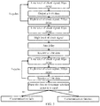
- FIG. 1 is a schematic flow chart of a quick charging method in accordance with an embodiment of the present disclosure.
- the method is applied to a power adapter.
- the power adapter is coupled to a mobile terminal via a universal serial bus (USB) interface.
- the USB interface can be a normal USB interface, and can also be a micro USB interface.
- a power line of the USB interface is used for the power adapter to charge the mobile terminal, and the power line of the USB interface can be a VBus line and/or grounding line.
- the power adapter supports a normal charging mode and a quick charging mode, and a charging current corresponding to the quick charging mode is greater than a charging current corresponding to the normal charging mode.
- the charging current corresponding to the normal charging mode is generally less than 2.5A, and the charging current corresponding to the quick charging mode can be greater than 3A.
- the method of FIG. 1 includes the following.
- the power adapter transmits clock signal to the mobile terminal via a first data line of the USB interface in a process of that the power adapter is coupled to the mobile terminal, and the clock signal is used to indicate a communication sequence between the power adapter and the mobile terminal.
- the power adapter actively transmits the clock signal to the mobile terminal, and keeps transmission of the clock signal during the whole process of that the power adapter is coupled to the mobile terminal.
- the power adapter conducts a bidirectional communication with the mobile terminal via a second data line of the USB interface under control of the communication sequence, so as to determine to charge the mobile terminal in the quick charging mode.
- the power adapter adjusts a charging current of the power adapter to the charging current corresponding to the quick charging mode to charge the mobile terminal.
- the power adapter can record the charging current corresponding to the quick charging mode in advance.
- the charging current of the power adapter is directly adjusted to the charging current corresponding to the quick charging mode.
- the power adapter can negotiate with the mobile terminal via the bidirectional communication to determine the charging current corresponding to the quick charging mode. After negotiation, the charging current is adjusted.
- the power adapter does not increase the charging current blindly to implement quick charging, but negotiates with the mobile terminal via the bidirectional communication with the mobile terminal to determine whether or not the quick charging mode can be adopted. Comparing with the present technology, the security of the quick charging process is improved.
- the communication sequence includes instruction transmission time slots of the power adapter and instruction reception time slots of the power adapter, and the instruction transmission time slots and the instruction reception time slots are alternatively generated.
- Conducting, by the power adapter, a bidirectional communication with the mobile terminal via a second data line of the USB interface under control of the communication sequence to determine to charge the mobile terminal in the quick charging mode includes: transmitting, by the power adapter, a first instruction to the mobile terminal via the second data line during the instruction transmission time slot of the power adapter, wherein the first instruction is used to query the mobile terminal for whether or not to activate the quick charging mode; receiving, by the power adapter, a reply instruction corresponding to the first instruction via the second data line during the instruction reception time slot of the power adapter, wherein the reply instruction corresponding to the first instruction is used for indicating that the mobile terminal agrees to activate the quick charging mode; and determining, by the power adapter, to charge the mobile terminal in the quick charging mode according to the reply instruction corresponding to the first instruction.
- the instruction transmission time slot of the power adapter includes a number of clock periods, and each clock period is used for transmitting a 1-bit data.
- the instruction transmission time slot of the power adapter includes eight clock periods, and the first instruction includes an 8-bit data.
- the instruction reception time slot of the power adapter includes a number of clock periods, and each clock period is used for receiving 1-bit data.
- the instruction reception time slot of the power adapter includes ten clock periods, and the reply instruction corresponding to the first instruction includes a 10-bit data.
- the first instruction is an instruction of the quick charging communication instruction set of the power adapter, and instructions of the quick charging communication instruction set have the same previous n bits.
- each clock period of the clock signal includes a low level of 10 ⁇ s and a high level of 500 ⁇ s.
- the first data line is a D+ data line of the USB interface
- the second data line is a D- data line of the USB interface
- FIG. 2 is a schematic flow chart of a quick charging method in accordance with an embodiment of the present disclosure.
- the method illustrated in FIG. 2 is applied to a mobile terminal.
- the mobile terminal is coupled to a power adapter via a USB interface.
- a power line of the USB interface is used for the power adapter to charge the mobile terminal.
- the mobile terminal supports a normal charging mode and a quick charging mode, and a charging current corresponding to the quick charging mode is greater than a charging current corresponding to the normal charging mode.
- the method of FIG. 2 includes the following.
- the mobile terminal receives clock signal from the power adapter via a first data line of the USB interface in a process of that the mobile terminal is coupled to the power adapter, and the clock signal is used to indicate a communication sequence between the mobile terminal and the power adapter.
- the mobile terminal conducts a bidirectional communication with the power adapter via a second data line of the USB interface under control of the communication sequence, so as to cause the power adapter to determine to charge the mobile terminal in the quick charging mode.
- the mobile terminal receives the charging current corresponding to the quick charging mode from the power adapter to charge a battery of the mobile terminal.
- the power adapter does not increase the charging current blindly to implement quick charging, but negotiates with the mobile terminal via the bidirectional communication with the mobile terminal to determine whether or not the quick charging mode can be adopted. Comparing with related arts, the security of the quick charging process is improved.
- the communication sequence includes instruction reception time slots of the mobile terminal and instruction transmission time slots of the mobile terminal, and the instruction reception time slots and the instruction reception time slots are alternatively generated.
- Conducting, by the mobile terminal, the bidirectional communication with the power adapter via a second data line of the USB interface under control of the communication sequence to cause the power adapter to determine to charge the mobile terminal in the quick charging mode includes: receiving, by the mobile terminal, a first instruction from the power adapter via the second data line during the instruction reception time slot of the mobile terminal, wherein the first instruction is used to query the mobile terminal for whether or not to activate the quick charging mode; transmitting, by the mobile terminal, a reply instruction corresponding to the first instruction via the second data line during the instruction transmission time slot of the mobile terminal, wherein the reply instruction corresponding to the first instruction is used for indicating that the mobile terminal agrees to activate the quick charging mode.
- the instruction reception time slot of the mobile terminal includes a number of clock periods, and each clock period is used for receiving a 1-bit data.
- the instruction reception time slot of the mobile terminal includes eight clock periods, and the first instruction includes an 8-bit data.
- the instruction transmission time slot of the mobile terminal includes a number of clock periods, and each clock period is used for transmitting 1-bit data.
- the instruction transmission time slot of the mobile terminal includes ten clock periods
- the reply instruction corresponding to the first instruction includes a 10-bit data
- the reply instruction corresponding to the first instruction is an instruction of the quick charging communication instruction set of the mobile terminal, and instructions of the quick charging communication instruction set have the same previous n bits.
- each clock period of the clock signal includes a low level of 10 ⁇ s and a high level of 500 ⁇ s.
- the first data line is a D+ data line of the USB interface
- the second data line is a D- data line of the USB interface
- FIGS. 3-5 are just used to help those skilled in the art to understand the embodiments of the present disclosure, and not used to limit the embodiments of the present disclosure to detailed values or detailed scenarios which are shown in the examples.
- those skilled in the art can make various equivalent modification or change according to the examples shown in FIGS. 3-5 , and such modification or change shall fall within the scope of the embodiments of the present disclosure.
- the quick charging communication instruction set of the power adapter and the mobile terminal can be defined.
- the quick charging communication instruction set is shown in the table 1.
- the power adapter firstly transmits an 8-bit data, and then the mobile terminal returns a 10-bit data.
- the power adapter can firstly transmit most significant bit (MSB).
- MSB most significant bit
- the power adapter receives a data
- the power adapter firstly receives MSB.
- the clock signal for data transmission and data reception of the power adapter can be provided by the power adapter.
- the power adapter When the power adapter transmits a data, the power adapter transmits each bit of the data before transmitting the clock interrupt signal, which can guarantee the accuracy of the data received by the mobile terminal.
- the power adapter When the power adapter receives a data, the power adapter can firstly transmit the clock interrupt signal, and then receive each bit of the data after a certain time, which can guarantee the accuracy and reliability of the data received by the power adapter.
- FIG. 3 is a schematic view showing that the power adapter implements a data reception and data transmission in accordance with an embodiment of the present disclosure.
- previous n bits of a data can be defined as 101 in advance.
- the data is determined as an invalid data, and communication fails.
- a received data is defined to include 10 bits in advance. If a received data does not include 10 bits, the received data is determined as an invalid data, and communication fails.
- FIG. 4 is a schematic view of a sequence of that the power adapter implements a communication in accordance with an embodiment of the present disclosure. From FIG. 4 , a relationship between a communication sequence indicated by the clock signal which is transmitted by the D+ data line and data signal transmitted by the D-data line is shown.
- FIG. 5 illustrates a detailed example. In FIG. 5 , after the power adapter transmits the instruction 10101000 to the mobile terminal, the power adapter receives the reply instruction 1011001111 from the mobile terminal.
- FIGS. 6-7 the following will specifically describe the power adapter and the mobile terminal of the embodiments of the present disclosure. It can be understood that the power adapter of FIG. 6 can implement various steps executed by the power adapter of FIGS. 1-5 , and the mobile terminal of FIG. 7 can implement various steps executed by the mobile terminal of FIGS. 1-5 . To avoid repetition, detailed description will be omitted.
- FIG. 6 is a schematic structural diagram of a power adapter in accordance with an embodiment of the present disclosure.
- a power adapter 600 in FIG. 6 is coupled to a mobile terminal via a USB interface.
- a power line of the USB interface is used for the power adapter 600 to charge the mobile terminal.
- the power adapter 600 supports a normal charging mode and a quick charging mode, and a charging current corresponding to the quick charging mode is greater than a charging current corresponding to the normal charging mode.
- the power adapter 600 includes the following.
- a communication circuit 610 is configured to transmit clock signal to the mobile terminal via a first data line of the USB interface in a process of that the power adapter 600 is coupled to the mobile terminal, and the clock signal is used to indicate a communication sequence between the power adapter 600 and the mobile terminal.
- the communication circuit 610 is further configured to conduct a bidirectional communication with the mobile terminal via a second data line of the USB interface under control of the communication sequence, so as to determine to charge the mobile terminal in the quick charging mode.
- a current adjusting circuit 620 is configured to adjust a charging current of the power adapter to the charging current corresponding to the quick charging mode to charge the mobile terminal.
- the power adapter does not increase the charging current blindly to implement quick charging, but negotiates with the mobile terminal via the bidirectional communication with the mobile terminal to determine whether or not the quick charging mode can be adopted. Comparing with the related art, the security of the quick charging process is improved.
- the communication sequence includes instruction transmission time slots of the power adapter 600 and instruction reception time slots of the power adapter 600, and the instruction transmission time slots and the instruction reception time slots are alternatively generated.
- the communication circuit 610 is configured to transmit a first instruction to the mobile terminal via the second data line during the instruction transmission time slot of the power adapter 600, and the first instruction is used to query the mobile terminal for whether or not to activate the quick charging mode.
- the communication circuit 610 is further configured to receive a reply instruction corresponding to the first instruction via the second data line during the instruction reception time slot of the power adapter 600, and the reply instruction corresponding to the first instruction is used for indicating that the mobile terminal agrees to activate the quick charging mode.
- the communication circuit 610 is further configured to determine to charge the mobile terminal in the quick charging mode according to the reply instruction corresponding to the first instruction.
- the instruction transmission time slot of the power adapter 600 includes a number of clock periods, and each clock period is used for transmitting a 1-bit data.
- the instruction transmission time slot of the power adapter 600 includes eight clock periods, and the first instruction includes an 8-bit data.
- the instruction reception time slot of the power adapter 600 includes a number of clock periods, and each clock period is used for receiving a 1-bit data.
- the instruction reception time slot of the power adapter 600 includes ten clock periods, and the reply instruction corresponding to the first instruction includes a 10-bit data.
- the first instruction is an instruction of the quick charging communication instruction set of the power adapter 600, and instructions of the quick charging communication instruction set have the same previous n bits.
- each clock period of the clock signal includes a low level of 10 ⁇ s and a high level of 500us.
- the first data line is a D+ data line of the USB interface
- the second data line is a D- data line of the USB interface
- FIG. 7 is a schematic block diagram of a mobile terminal in accordance with an embodiment of the present disclosure.
- a mobile terminal 700 in FIG. 7 is coupled to a power adapter via a USB interface.
- a power line of the USB interface is used for the power adapter to charge the mobile terminal 700.
- the mobile terminal 700 supports a normal charging mode and a quick charging mode, and a charging current corresponding to the quick charging mode is greater than a charging current corresponding to the normal charging mode.
- the mobile terminal 700 includes the following.
- a communication circuit 710 is configured to receive clock signal from the power adapter via a first data line of the USB interface in a process of that the mobile terminal 700 is coupled to the power adapter, and the clock signal is used to indicate a communication sequence between the mobile terminal 700 and the power adapter.
- the communication circuit 710 is further configured to conduct a bidirectional communication with the power adapter via a second data line of the USB interface under control of the communication sequence, so as to cause the power adapter to determine to charge the mobile terminal 700 in the quick charging mode.
- a charging circuit 720 is configured to receive the charging current corresponding to the quick charging mode from the power adapter to charge a battery of the mobile terminal 700.
- the power adapter does not increase the charging current blindly to implement quick charging, but negotiates with the mobile terminal via the bidirectional communication with the mobile terminal to determine whether or not the quick charging mode can be adopted. Comparing to the present technology, the security of the quick charging process is improved.
- the communication sequence includes instruction reception time slots of the mobile terminal 700 and instruction transmission time slots of the mobile terminal 700, and the instruction reception time slots and the instruction transmission time slots are alternatively generated.
- the communication circuit 710 is configured to receive a first instruction from the power adapter via the second data line during the instruction reception time slot of the mobile terminal 700, and the first instruction is used to query the mobile terminal 700 for whether or not to activate the quick charging mode.
- the communication circuit 710 is further configured to transmit a reply instruction corresponding to the first instruction to the power adapter via the second data line during the instruction transmission time slot of the mobile terminal 700, and the reply instruction corresponding to the first instruction is used for indicating that the mobile terminal 700 agrees to activate the quick charging mode.
- the instruction reception time slot of the mobile terminal 700 includes a number of clock periods, and each clock period is used for receiving a 1-bit data.
- the instruction reception time slot of the mobile terminal 700 includes eight clock periods, and the first instruction includes an 8-bit data.
- the instruction transmission time slot of the mobile terminal 700 includes a number of clock periods, and each clock period is used for transmitting a 1-bit data.
- the instruction transmission time slot of the mobile terminal 700 includes ten clock periods, and the reply instruction corresponding to the first instruction includes a 10-bit data.
- the reply instruction corresponding to the first instruction is an instruction of the quick charging communication instruction set of the mobile terminal 700, and instructions of the quick charging communication instruction set have the same previous n bits.
- each clock period of the clock signal includes a low level of 10us and a high level of 500us.
- the first data line is a D+ data line of the USB interface
- the second data line is a D- data line of the USB interface
- the disclosed systems, devices, and methods can be implemented by other manners.
- the device embodiments described above are only schematic.
- the units are divided according to logic functions and can be divided by another manner in an actual implementation.
- several units or assemblies can be combined or can be integrated into another system, or some features can be ignored, or are not executed.
- mutual coupling or direct coupling or communication connection shown or discussed herein can be indirect coupling or communication connection through certain interfaces, devices, or units, and can be in the form of electricity, machine, or other.
- the units illustrated as separate units can be or cannot be physically separated, and components shown in units can be or cannot be physical units, that is, can be in a place, or can be distributed in several network units. A part of or all of the units can be selected according to actual need to realize the purpose of the solution of the embodiments.
- various functional units in the embodiments of the present disclosure can be integrated into one processing unit, or various functional units can exist alone, or two or more units can be integrated into one unit.
- the functions can be realized in the form of software functional units and can be sold or used as stand-alone products, they can be stored in a computer-readable storage medium.
- the technical solution of the present disclosure or the part that contributes to the existing technology or a part of the technical solution can be embodied in the form of a software product.
- the computer software product can be stored in a storage medium, and include a plurality of instructions configured to direct a computer device (personal computer, server, or network device) to execute all of or a part of steps of various embodiments of the present disclosure.
- the storage mediums described above include a U disk, a mobile disk, a read-only memory (ROM), a random access memory (RAM), a disc, a compact disc, or other medium storing program codes.
Landscapes
- Engineering & Computer Science (AREA)
- Power Engineering (AREA)
- Signal Processing (AREA)
- Manufacturing & Machinery (AREA)
- Chemical & Material Sciences (AREA)
- Chemical Kinetics & Catalysis (AREA)
- Electrochemistry (AREA)
- General Chemical & Material Sciences (AREA)
- Charge And Discharge Circuits For Batteries Or The Like (AREA)
- Telephone Function (AREA)
Abstract
Description
- The present disclosure relates to charging field, and more particularly to a quick charging method, a power adapter, and a mobile terminal.
- Presently, mobile terminals (e.g., smart phones) become more and more popular with consumers. However, the power consumption of mobile terminals is great, thus mobile terminals need to be charged regularly. As the battery capacity of mobile terminals becomes greater and greater, correspondingly, the charging time becomes longer. How to realize quick charging is a problem that needed to be solved instantly.
- In the present technology, to achieve the purpose of quick charging, the output current of a power adapter is directly increased without consideration of endurance of a mobile terminal, which will result in a phenomenon of overheating and even burnout of the mobile terminal, and reduces the lifespan of the mobile terminal.
- The embodiments of the present disclosure provide a quick charging method, a power adapter, and a mobile terminal, which can increase security of a quick charging process.
- A first aspect provides a quick charging method. The method is applied to a power adapter. The power adapter is coupled to a mobile terminal via a USB interface. A power line of the USB interface is used for the power adapter to charge the mobile terminal. The power adapter supports a normal charging mode and a quick charging mode, and a charging current corresponding to the quick charging mode is greater than a charging current corresponding to the normal charging mode. The method comprises: transmitting, by the power adapter, clock signal to the mobile terminal via a first data line of the USB interface in a process of that the power adapter is coupled to the mobile terminal, wherein the clock signal is used for indicating a communication sequence between the power adapter and the mobile terminal; conducting, by the power adapter, a bidirectional communication with the mobile terminal via a second data line of the USB interface under control of the communication sequence to determine to charge the mobile terminal in the quick charging mode; and adjusting, by the power adapter, a charging current of the power adapter to the charging current corresponding to the quick charging mode to charge the mobile terminal.
- In combination with the first aspect, in an implementation manner of the first aspect, the communication sequence comprises instruction transmission time slots of the power adapter and instruction reception time slots of the power adapter, and the instruction transmission time slots and the instruction reception time slots are alternatively generated. Conducting, by the power adapter, a bidirectional communication with the mobile terminal via a second data line of the USB interface under control of the communication sequence to determine to charge the mobile terminal in the quick charging mode comprises: transmitting, by the power adapter, a first instruction to the mobile terminal via the second data line during the instruction transmission time slot of the power adapter, wherein the first instruction is used for querying the mobile terminal for whether or not to activate the quick charging mode; receiving, by the power adapter, a reply instruction corresponding to the first instruction via the second data line during the instruction reception time slot of the power adapter, wherein the reply instruction corresponding to the first instruction is used for indicating that the mobile terminal agrees to activate the quick charging mode; and determining, by the power adapter, to charge the mobile terminal in the quick charging mode according to the reply instruction corresponding to the first instruction.
- In combination with the first aspect or any of the above implementation manners, in another implementation manner of the first aspect, the instruction transmission time slot of the power adapter comprises a plurality of clock periods, and each of the plurality of clock periods is used for transmitting a 1-bit data.
- In combination with the first aspect or any of the above implementation manners, in another implementation manner of the first aspect, the instruction transmission time slot of the power adapter comprises eight clock periods, and the first instruction comprises an 8-bit data.
- In combination with the first aspect or any of the above implementation manners, in another implementation manner of the first aspect, the instruction reception time slot of the power adapter comprises a plurality of clock periods, and each of the plurality of clock periods is used for receiving a 1-bit data.
- In combination with the first aspect or any of the above implementation manners, in another implementation manner of the first aspect, the instruction reception time slot of the power adapter comprises ten clock periods, and the reply instruction corresponding to the first instruction comprises a 10-bit data.
- In combination with the first aspect or any of the above implementation manners, in another implementation manner of the first aspect, the first instruction is an instruction of a quick charging communication instruction set of the power adapter, and instructions of the quick charging communication instruction set have the same previous n bits.
- In combination with the first aspect or any of the above implementation manners, in another implementation manner of the first aspect, each clock period of the clock signal comprises a low level of 10µs and a high level of 500µs.
- In combination with the first aspect or any of the above implementation manners, in another implementation manner of the first aspect, the first data line is a D+ data line of the USB interface, and the second data line is a D- data line of the USB interface.
- A second aspect provides a quick charging method. The method is applied to a mobile terminal. The mobile terminal is coupled to a power adapter via a USB interface. A power line of the USB interface is used for the power adapter to charge the mobile terminal. The mobile terminal supports a normal charging mode and a quick charging mode, and a charging current corresponding to the quick charging mode is greater than a charging current corresponding to the normal charging mode. The method comprises: receiving, by the mobile terminal, clock signal from the power adapter via a first data line of the USB interface in a process of that the mobile terminal is coupled to the power adapter, wherein the clock signal is used for indicating a communication sequence between the mobile terminal and the power adapter; conducting, by the mobile terminal, a bidirectional communication with the power adapter via a second data line of the USB interface under control of the communication sequence to cause the power adapter to determine to charge the mobile terminal in the quick charging mode; and receiving, by the mobile terminal, the charging current corresponding to the quick charging mode from the power adapter to charge a battery of the mobile terminal.
- In combination with the second aspect, in an implementation of the second aspect, the communication sequence comprises instruction reception time slots of the mobile terminal and instruction transmission time slots of the mobile terminal, and the instruction reception time slots and the instruction transmission time slots are alternatively generated. Conducting, by the mobile terminal, a bidirectional communication with the power adapter via a second data line of the USB interface under control of the communication sequence to cause the power adapter to determine to charge the mobile terminal in the quick charging mode comprises: receiving, by the mobile terminal, a first instruction from the power adapter via the second data line during the instruction reception time slot of the mobile terminal, wherein the first instruction is used to query the mobile terminal for whether or not to activate the quick charging mode; and transmitting, by the mobile terminal, a reply instruction corresponding to the first instruction to the power adapter via the second data line during the instruction transmission time slot of the power adapter, wherein the reply instruction corresponding to the first instruction is used for indicating that the mobile terminal agrees to activate the quick charging mode.
- In combination with the second aspect or any of the above implementation manners, in another implementation manner of the second aspect, the instruction reception time slot of the mobile terminal comprises a plurality of clock periods, and each of the plurality of clock periods is used for receiving a 1-bit data.
- In combination with the second aspect or any of the above implementation manners, in another implementation manner of the second aspect, the instruction reception time slot of the mobile terminal comprises eight clock periods, and the first instruction comprises an 8-bit data.
- In combination with the second aspect or any of the above implementation manners, in another implementation manner of the second aspect, the instruction transmission time slot of the mobile terminal comprises a plurality of clock periods, and each of the plurality of clock periods is used for transmitting a 1-bit data.
- In combination with the second aspect or any of the above implementation manners, in another implementation manner of the second aspect, the instruction transmission time slot of the mobile terminal comprises ten clock periods, and the reply instruction corresponding to the first instruction comprises a 10-bit data.
- In combination with the second aspect or any of the above implementation manners, in another implementation manner of the second aspect, the reply instruction corresponding to the first instruction is an instruction of a quick charging communication instruction set of the mobile terminal, and instructions of the quick charging communication instruction set have the same previous n bits.
- In combination with the second aspect or any of the above implementation manners, in another implementation manner of the second aspect, each clock period of the clock signal comprises a low level of 10µs and a high level of 500µs.
- In combination with the second aspect or any of the above implementation manners, in another implementation manner of the second aspect, the first data line is a D+ data line of the USB interface, and the second data line is a D- data line of the USB interface.
- A third aspect provides a power adapter. The power adapter is coupled to a mobile terminal via a USB interface. A power line of the USB interface is used for the power adapter to charge the mobile terminal. The power adapter supports a normal charging mode and a quick charging mode, and a charging current corresponding to the quick charging mode is greater than a charging current corresponding to the normal charging mode. The power adapter comprises a communication unit configured to transmit clock signal to the mobile terminal via a first data line of the USB interface in a process of that the power adapter is coupled to the mobile terminal, wherein the clock signal is used for indicating a communication sequence between the power adapter and the mobile terminal. The communication unit is further configured to conduct a bidirectional communication with the mobile terminal via a second data line of the USB interface under control of the communication sequence to determine to charge the mobile terminal in the quick charging mode. The power adapter further comprises a current adjusting unit configured to adjust a charging current of the power adapter to the charging current corresponding to the quick charging mode to charge the mobile terminal.
- In combination with the third aspect, in an implementation manner of the third aspect, the communication sequence comprises instruction transmission time slots of the power adapter and instruction reception time slots of the power adapter, and the instruction transmission time slots and the instruction reception time slots are alternatively generated. The communication unit is configured to transmit a first instruction to the mobile terminal via the second data line during the instruction transmission time slot of the power adapter, and the first instruction is used to query the mobile terminal for whether or not to activate the quick charging mode. The communication unit is further configured to receive a reply instruction corresponding to the first instruction via the second data line during the instruction reception time slot of the power adapter, and the reply instruction corresponding to the first instruction is used for indicating that the mobile terminal agrees to activate the quick charging mode. The communication unit is further configured to determine to charge the mobile terminal in the quick charging mode according to the reply instruction corresponding to the first instruction.
- In combination with the third aspect or any of the above implementation manners, in another implementation manner of the third aspect, the instruction transmission time slot of the power adapter comprises a plurality of clock periods, and each of the plurality of clock periods is used for transmitting a 1-bit data.
- In combination with the third aspect or any of the above implementation manners, in another implementation manner of the third aspect, the instruction transmission time slot of the power adapter comprises eight clock periods, and the first instruction comprises an 8-bit data.
- In combination with the third aspect or any of the above implementation manners, in another implementation manner of the third aspect, the instruction reception time slot of the power adapter comprises a plurality of clock periods, and each of the plurality of clock periods is used for receiving a 1-bit data.
- In combination with the third aspect or any of the above implementation manners, in another implementation manner of the third aspect, the instruction reception time slot of the power adapter comprises ten clock periods, and the reply instruction corresponding to the first instruction comprises a 10-bit data.
- In combination with the third aspect or any of the above implementation manners, in another implementation manner of the third aspect, the first instruction is an instruction of a quick charging communication instruction set of the power adapter, and instructions of the quick charging communication instruction set have the same previous n bits.
- In combination with the third aspect or any of the above implementation manners, in another implementation manner of the third aspect, each clock period of the clock signal comprises a low level of 10µs and a high level of 500µs.
- In combination with the third aspect or any of the above implementation manners, in another implementation manner of the third aspect, the first data line is a D+ data line of the USB interface, and the second data line is a D- data line of the USB interface.
- A fourth aspect provides a mobile terminal. The mobile terminal is coupled to a power adapter via a USB interface. A power line of the USB interface is used for the power adapter to charge the mobile terminal. The mobile terminal supports a normal charging mode and a quick charging mode, and a charging current corresponding to the quick charging mode is greater than a charging current corresponding to the normal charging mode. The mobile terminal includes a communication unit configured to receive clock signal from the power adapter via a first data line of the USB interface in a process of that the mobile terminal is coupled to the power adapter, wherein the clock signal is used for indicating a communication sequence between the mobile terminal and the power adapter. The communication unit is further configured to conduct a bidirectional communication with the power adapter via a second data line of the USB interface under control of the communication sequence to cause the power adapter to determine to charge the mobile terminal in the quick charging mode. The mobile terminal further comprises a charging unit configured to receive the charging current corresponding to the quick charging mode from the power adapter to charge a battery of the mobile terminal.
- In combination with the fourth aspect, in an implementation manner of the fourth aspect, the communication sequence comprises instruction reception time slots of the mobile terminal and instruction transmission time slots of the mobile terminal, and the instruction reception time slots and the instruction transmission time slots are alternatively generated. The communication unit is configured to receive a first instruction from the power adapter via the second data line during the instruction reception time slot of the mobile terminal, and the first instruction is used to query the mobile terminal for whether or not to activate the quick charging mode. The communication unit is further configured to transmit a reply instruction corresponding to the first instruction to the power adapter via the second data line during the instruction transmission time slot of the mobile terminal, and the reply instruction corresponding to the first instruction is used for indicating that the mobile terminal agrees to activate the quick charging mode.
- In combination with the fourth aspect or any of the above implementation manners, in another implementation manner of the fourth aspect, the instruction reception time slot of the mobile terminal comprises a plurality of clock periods, and each of the plurality of clock periods is used for receiving a 1-bit data.
- In combination with the fourth aspect or any of the above implementation manners, in another implementation manner of the fourth aspect, the instruction reception time slot of the mobile terminal comprises eight clock periods, and the first instruction comprises an 8-bit data.
- In combination with the fourth aspect or any of the above implementation manners, in another implementation manner of the fourth aspect, the instruction transmission time slot of the mobile terminal comprises a plurality of clock periods, and each of the plurality of clock periods is used for transmitting a 1-bit data.
- In combination with the fourth aspect or any of the above implementation manners, in another implementation manner of the fourth aspect, the instruction transmission time slot of the mobile terminal comprises ten clock periods, and the reply instruction corresponding to the first instruction comprises a 10-bit data.
- In combination with the fourth aspect or any of the above implementation manners, in another implementation manner of the fourth aspect, the reply instruction corresponding to the first instruction is an instruction of a quick charging communication instruction set of the mobile terminal, and instructions of the quick charging communication instruction set have the same previous n bits.
- In combination with the fourth aspect or any of the above implementation manners, in another implementation manner of the fourth aspect, each clock period of the clock signal comprises a low level of 10µs and a high level of 500µs.
- In combination with the fourth aspect or any of the above implementation manners, in another implementation manner of the fourth aspect, the first data line is a D+ data line of the USB interface, and the second data line is a D- data line of the USB interface.
- In embodiments of the present disclosure, the power adapter does not increase the charging current blindly to implement quick charging, but negotiates with the mobile terminal via the bidirectional communication with the mobile terminal to determine whether or not the quick charging mode can be adopted. Comparing with the present technology, the security of the quick charging process is improved.
- To better illustrate the technical solution of embodiments of the present disclosure, the following descriptions will briefly illustrate the accompanying drawings described in the embodiments. Obviously, the following described accompanying drawings are some embodiments of the present disclosure. Those skilled in the art can obtain other accompanying drawings according to the described accompanying drawings without creative work.
-
FIG. 1 is a schematic flow chart of a quick charging method in accordance with an embodiment of the present disclosure. -
FIG. 2 is a schematic flow chart of a quick charging method in accordance with another embodiment of the present disclosure. -
FIG. 3 is a schematic view showing that a power adapter implements a data reception and transmission in accordance with an embodiment of the present disclosure. -
FIG. 4 is a schematic view of a sequence of that the power adapter implements a communication in accordance with an embodiment of the present disclosure. -
FIG. 5 is a schematic view of a sequence of that the power adapter implements a communication in accordance with another embodiment of the present disclosure. -
FIG. 6 is a diagrammatic view of a structure of a power adapter in accordance with an embodiment of the present disclosure. -
FIG. 7 is diagrammatic view of a structure of a mobile terminal in accordance with an embodiment of the present disclosure. - The technical solution of embodiments of the present disclosure will be described clearly and completely in combination with the accompanying drawings of the embodiments of the present disclosure. Obviously, the described embodiments are a part of embodiments of the present disclosure, and not all of the embodiments. According to the embodiments of the present disclosure, other embodiments obtained by those skilled in the art without creative work all fall within the protection scope of the present disclosure.
-
FIG. 1 is a schematic flow chart of a quick charging method in accordance with an embodiment of the present disclosure. The method is applied to a power adapter. The power adapter is coupled to a mobile terminal via a universal serial bus (USB) interface. The USB interface can be a normal USB interface, and can also be a micro USB interface. A power line of the USB interface is used for the power adapter to charge the mobile terminal, and the power line of the USB interface can be a VBus line and/or grounding line. The power adapter supports a normal charging mode and a quick charging mode, and a charging current corresponding to the quick charging mode is greater than a charging current corresponding to the normal charging mode. For example, the charging current corresponding to the normal charging mode is generally less than 2.5A, and the charging current corresponding to the quick charging mode can be greater than 3A. - The method of
FIG. 1 includes the following. - At
block 110, the power adapter transmits clock signal to the mobile terminal via a first data line of the USB interface in a process of that the power adapter is coupled to the mobile terminal, and the clock signal is used to indicate a communication sequence between the power adapter and the mobile terminal. - It should be understood that the power adapter actively transmits the clock signal to the mobile terminal, and keeps transmission of the clock signal during the whole process of that the power adapter is coupled to the mobile terminal.
- At
block 120, the power adapter conducts a bidirectional communication with the mobile terminal via a second data line of the USB interface under control of the communication sequence, so as to determine to charge the mobile terminal in the quick charging mode. - At
block 130, the power adapter adjusts a charging current of the power adapter to the charging current corresponding to the quick charging mode to charge the mobile terminal. - In detail, the power adapter can record the charging current corresponding to the quick charging mode in advance. When it is determined that the quick charging mode is adopted to charge the mobile terminal, the charging current of the power adapter is directly adjusted to the charging current corresponding to the quick charging mode. Or, the power adapter can negotiate with the mobile terminal via the bidirectional communication to determine the charging current corresponding to the quick charging mode. After negotiation, the charging current is adjusted.
- In embodiments of the present disclosure, the power adapter does not increase the charging current blindly to implement quick charging, but negotiates with the mobile terminal via the bidirectional communication with the mobile terminal to determine whether or not the quick charging mode can be adopted. Comparing with the present technology, the security of the quick charging process is improved.
- Optionally, in an embodiment, the communication sequence includes instruction transmission time slots of the power adapter and instruction reception time slots of the power adapter, and the instruction transmission time slots and the instruction reception time slots are alternatively generated. Conducting, by the power adapter, a bidirectional communication with the mobile terminal via a second data line of the USB interface under control of the communication sequence to determine to charge the mobile terminal in the quick charging mode, includes: transmitting, by the power adapter, a first instruction to the mobile terminal via the second data line during the instruction transmission time slot of the power adapter, wherein the first instruction is used to query the mobile terminal for whether or not to activate the quick charging mode; receiving, by the power adapter, a reply instruction corresponding to the first instruction via the second data line during the instruction reception time slot of the power adapter, wherein the reply instruction corresponding to the first instruction is used for indicating that the mobile terminal agrees to activate the quick charging mode; and determining, by the power adapter, to charge the mobile terminal in the quick charging mode according to the reply instruction corresponding to the first instruction.
- Optionally, in an embodiment, the instruction transmission time slot of the power adapter includes a number of clock periods, and each clock period is used for transmitting a 1-bit data.
- Optionally, in an embodiment, the instruction transmission time slot of the power adapter includes eight clock periods, and the first instruction includes an 8-bit data.
- Optionally, in an embodiment, the instruction reception time slot of the power adapter includes a number of clock periods, and each clock period is used for receiving 1-bit data.
- Optionally, in an embodiment, the instruction reception time slot of the power adapter includes ten clock periods, and the reply instruction corresponding to the first instruction includes a 10-bit data.
- Optionally, in an embodiment, the first instruction is an instruction of the quick charging communication instruction set of the power adapter, and instructions of the quick charging communication instruction set have the same previous n bits.
- Optionally, in an embodiment, each clock period of the clock signal includes a low level of 10µs and a high level of 500µs.
- Optionally, in an embodiment, the first data line is a D+ data line of the USB interface, and the second data line is a D- data line of the USB interface.
- The above description in combination with
FIG. 1 describes the quick charging method of the embodiments of the present disclosure executed by the power adapter. The following description in combination withFIG. 2 will describes the quick charging method of the embodiments of the present disclosure executed by the mobile terminal. - It can be understood that interaction and relevance properties and functions of the power adapter and the mobile terminal described in the quick charging method executed by the mobile terminal corresponds to the description of the quick charging method executed by the power adapter. For simplicity, repeated description will be omitted appropriately.
-
FIG. 2 is a schematic flow chart of a quick charging method in accordance with an embodiment of the present disclosure. The method illustrated inFIG. 2 is applied to a mobile terminal. The mobile terminal is coupled to a power adapter via a USB interface. A power line of the USB interface is used for the power adapter to charge the mobile terminal. The mobile terminal supports a normal charging mode and a quick charging mode, and a charging current corresponding to the quick charging mode is greater than a charging current corresponding to the normal charging mode. The method ofFIG. 2 includes the following. - At
block 210, the mobile terminal receives clock signal from the power adapter via a first data line of the USB interface in a process of that the mobile terminal is coupled to the power adapter, and the clock signal is used to indicate a communication sequence between the mobile terminal and the power adapter. - At
block 220, the mobile terminal conducts a bidirectional communication with the power adapter via a second data line of the USB interface under control of the communication sequence, so as to cause the power adapter to determine to charge the mobile terminal in the quick charging mode. - At
block 230, the mobile terminal receives the charging current corresponding to the quick charging mode from the power adapter to charge a battery of the mobile terminal. - In embodiments of the present disclosure, the power adapter does not increase the charging current blindly to implement quick charging, but negotiates with the mobile terminal via the bidirectional communication with the mobile terminal to determine whether or not the quick charging mode can be adopted. Comparing with related arts, the security of the quick charging process is improved.
- Optionally, in an embodiment, the communication sequence includes instruction reception time slots of the mobile terminal and instruction transmission time slots of the mobile terminal, and the instruction reception time slots and the instruction reception time slots are alternatively generated. Conducting, by the mobile terminal, the bidirectional communication with the power adapter via a second data line of the USB interface under control of the communication sequence to cause the power adapter to determine to charge the mobile terminal in the quick charging mode includes: receiving, by the mobile terminal, a first instruction from the power adapter via the second data line during the instruction reception time slot of the mobile terminal, wherein the first instruction is used to query the mobile terminal for whether or not to activate the quick charging mode; transmitting, by the mobile terminal, a reply instruction corresponding to the first instruction via the second data line during the instruction transmission time slot of the mobile terminal, wherein the reply instruction corresponding to the first instruction is used for indicating that the mobile terminal agrees to activate the quick charging mode.
- Optionally, in an embodiment, the instruction reception time slot of the mobile terminal includes a number of clock periods, and each clock period is used for receiving a 1-bit data.
- Optionally, in an embodiment, the instruction reception time slot of the mobile terminal includes eight clock periods, and the first instruction includes an 8-bit data.
- Optionally, in an embodiment, the instruction transmission time slot of the mobile terminal includes a number of clock periods, and each clock period is used for transmitting 1-bit data.
- Optionally, in an embodiment, the instruction transmission time slot of the mobile terminal includes ten clock periods, and the reply instruction corresponding to the first instruction includes a 10-bit data.
- Optionally, in an embodiment, the reply instruction corresponding to the first instruction is an instruction of the quick charging communication instruction set of the mobile terminal, and instructions of the quick charging communication instruction set have the same previous n bits.
- Optionally, in an embodiment, each clock period of the clock signal includes a low level of 10µs and a high level of 500µs.
- Optionally, in an embodiment, the first data line is a D+ data line of the USB interface, and the second data line is a D- data line of the USB interface.
- The following will describe embodiments of the present disclosure more specifically in combination with detailed examples. It should be noted that examples illustrated in
FIGS. 3-5 are just used to help those skilled in the art to understand the embodiments of the present disclosure, and not used to limit the embodiments of the present disclosure to detailed values or detailed scenarios which are shown in the examples. Apparently, those skilled in the art can make various equivalent modification or change according to the examples shown inFIGS. 3-5 , and such modification or change shall fall within the scope of the embodiments of the present disclosure. - Firstly, the quick charging communication instruction set of the power adapter and the mobile terminal can be defined. For example, the quick charging communication instruction set is shown in the table 1.
Table 1 Quick charging communication instruction set Instruction 1: requesting for quick charging Power adapter->Mobile terminal 10101000 OxA8 Mobile terminal->Power adapter 101XYYYYYY X: 1->Agree 0->Disagree, Path impedance=YYYYYY*5(mΩ) Instruction 2: querying whether or not a voltage of the power adapter is proper Power adapter->Mobile terminal 10100100 OxA4 Mobile terminal->Power adapter 1010XX0000 XX: 11->proper 10->High 01 ->Low 00->Error Instruction 3: querying for a maximum charging current which is currently supported by the mobile terminal Power adapter->Mobile terminal 10100110 OxA6 Mobile terminal->Power adapter 1010XXXXXX Maximum charging current currently supported by the mobile terminal= 3000+ (XXXXXX*250)(mA) Instruction 4: querying for a current voltage of a battery of the mobile terminal Power adapter->Mobile terminal 10100010 OxA2 Mobile terminal->Power adapter 101XYYYYYY X: 1->being charged 0->Uncharged, Battery voltage = 3404+(YYYYYY* 16)(mV) Instruction 5: informing the mobile terminal that USB connection is poor and quick charging should be stopped Power adapter->Mobile terminal 10110010 OxB2 Mobile terminal->Power adapter NONE - From table 1, it can be seen that in each communication the power adapter firstly transmits an 8-bit data, and then the mobile terminal returns a 10-bit data. When the power adapter transmits a data, the power adapter can firstly transmit most significant bit (MSB). Similarly, when the power adapter receives a data, the power adapter firstly receives MSB. The clock signal for data transmission and data reception of the power adapter can be provided by the power adapter.
- When the power adapter transmits a data, the power adapter transmits each bit of the data before transmitting the clock interrupt signal, which can guarantee the accuracy of the data received by the mobile terminal. When the power adapter receives a data, the power adapter can firstly transmit the clock interrupt signal, and then receive each bit of the data after a certain time, which can guarantee the accuracy and reliability of the data received by the power adapter.
-
FIG. 3 is a schematic view showing that the power adapter implements a data reception and data transmission in accordance with an embodiment of the present disclosure. ForFIG. 3 , there are a number of methods for parsing a data to determine whether or not the data is valid. For example, previous n bits of a data can be defined as 101 in advance. When previous 3 bits of a data received by the power adapter is not 101, the data is determined as an invalid data, and communication fails. Or, a received data is defined to include 10 bits in advance. If a received data does not include 10 bits, the received data is determined as an invalid data, and communication fails. -
FIG. 4 is a schematic view of a sequence of that the power adapter implements a communication in accordance with an embodiment of the present disclosure. FromFIG. 4 , a relationship between a communication sequence indicated by the clock signal which is transmitted by the D+ data line and data signal transmitted by the D-data line is shown.FIG. 5 illustrates a detailed example. InFIG. 5 , after the power adapter transmits the instruction 10101000 to the mobile terminal, the power adapter receives the reply instruction 1011001111 from the mobile terminal. - In combination with
FIGS. 1-5 , the above describes the quick charging method of the embodiments of the present disclosure. Referring toFIGS. 6-7 , the following will specifically describe the power adapter and the mobile terminal of the embodiments of the present disclosure. It can be understood that the power adapter ofFIG. 6 can implement various steps executed by the power adapter ofFIGS. 1-5 , and the mobile terminal ofFIG. 7 can implement various steps executed by the mobile terminal ofFIGS. 1-5 . To avoid repetition, detailed description will be omitted. -
FIG. 6 is a schematic structural diagram of a power adapter in accordance with an embodiment of the present disclosure. Apower adapter 600 inFIG. 6 is coupled to a mobile terminal via a USB interface. A power line of the USB interface is used for thepower adapter 600 to charge the mobile terminal. Thepower adapter 600 supports a normal charging mode and a quick charging mode, and a charging current corresponding to the quick charging mode is greater than a charging current corresponding to the normal charging mode. Thepower adapter 600 includes the following. - A
communication circuit 610 is configured to transmit clock signal to the mobile terminal via a first data line of the USB interface in a process of that thepower adapter 600 is coupled to the mobile terminal, and the clock signal is used to indicate a communication sequence between thepower adapter 600 and the mobile terminal. Thecommunication circuit 610 is further configured to conduct a bidirectional communication with the mobile terminal via a second data line of the USB interface under control of the communication sequence, so as to determine to charge the mobile terminal in the quick charging mode. - A current adjusting circuit 620 is configured to adjust a charging current of the power adapter to the charging current corresponding to the quick charging mode to charge the mobile terminal.
- In embodiments of the present disclosure, the power adapter does not increase the charging current blindly to implement quick charging, but negotiates with the mobile terminal via the bidirectional communication with the mobile terminal to determine whether or not the quick charging mode can be adopted. Comparing with the related art, the security of the quick charging process is improved.
- Optionally, in an embodiment, the communication sequence includes instruction transmission time slots of the
power adapter 600 and instruction reception time slots of thepower adapter 600, and the instruction transmission time slots and the instruction reception time slots are alternatively generated. Thecommunication circuit 610 is configured to transmit a first instruction to the mobile terminal via the second data line during the instruction transmission time slot of thepower adapter 600, and the first instruction is used to query the mobile terminal for whether or not to activate the quick charging mode. Thecommunication circuit 610 is further configured to receive a reply instruction corresponding to the first instruction via the second data line during the instruction reception time slot of thepower adapter 600, and the reply instruction corresponding to the first instruction is used for indicating that the mobile terminal agrees to activate the quick charging mode. Thecommunication circuit 610 is further configured to determine to charge the mobile terminal in the quick charging mode according to the reply instruction corresponding to the first instruction. - Optionally, in an embodiment, the instruction transmission time slot of the
power adapter 600 includes a number of clock periods, and each clock period is used for transmitting a 1-bit data. - Optionally, in an embodiment, the instruction transmission time slot of the
power adapter 600 includes eight clock periods, and the first instruction includes an 8-bit data. - Optionally, in an embodiment, the instruction reception time slot of the
power adapter 600 includes a number of clock periods, and each clock period is used for receiving a 1-bit data. - Optionally, in an embodiment, the instruction reception time slot of the
power adapter 600 includes ten clock periods, and the reply instruction corresponding to the first instruction includes a 10-bit data. - Optionally, in an embodiment, the first instruction is an instruction of the quick charging communication instruction set of the
power adapter 600, and instructions of the quick charging communication instruction set have the same previous n bits. - Optionally, in an embodiment, each clock period of the clock signal includes a low level of 10µs and a high level of 500us.
- Optionally, in an embodiment, the first data line is a D+ data line of the USB interface, and the second data line is a D- data line of the USB interface.
-
FIG. 7 is a schematic block diagram of a mobile terminal in accordance with an embodiment of the present disclosure. Amobile terminal 700 inFIG. 7 is coupled to a power adapter via a USB interface. A power line of the USB interface is used for the power adapter to charge themobile terminal 700. Themobile terminal 700 supports a normal charging mode and a quick charging mode, and a charging current corresponding to the quick charging mode is greater than a charging current corresponding to the normal charging mode. Themobile terminal 700 includes the following. - A
communication circuit 710 is configured to receive clock signal from the power adapter via a first data line of the USB interface in a process of that themobile terminal 700 is coupled to the power adapter, and the clock signal is used to indicate a communication sequence between themobile terminal 700 and the power adapter. Thecommunication circuit 710 is further configured to conduct a bidirectional communication with the power adapter via a second data line of the USB interface under control of the communication sequence, so as to cause the power adapter to determine to charge themobile terminal 700 in the quick charging mode. - A charging
circuit 720 is configured to receive the charging current corresponding to the quick charging mode from the power adapter to charge a battery of themobile terminal 700. - In embodiments of the present disclosure, the power adapter does not increase the charging current blindly to implement quick charging, but negotiates with the mobile terminal via the bidirectional communication with the mobile terminal to determine whether or not the quick charging mode can be adopted. Comparing to the present technology, the security of the quick charging process is improved.
- Optionally, in an embodiment, the communication sequence includes instruction reception time slots of the
mobile terminal 700 and instruction transmission time slots of themobile terminal 700, and the instruction reception time slots and the instruction transmission time slots are alternatively generated. Thecommunication circuit 710 is configured to receive a first instruction from the power adapter via the second data line during the instruction reception time slot of themobile terminal 700, and the first instruction is used to query themobile terminal 700 for whether or not to activate the quick charging mode. Thecommunication circuit 710 is further configured to transmit a reply instruction corresponding to the first instruction to the power adapter via the second data line during the instruction transmission time slot of themobile terminal 700, and the reply instruction corresponding to the first instruction is used for indicating that themobile terminal 700 agrees to activate the quick charging mode. - Optionally, in an embodiment, the instruction reception time slot of the
mobile terminal 700 includes a number of clock periods, and each clock period is used for receiving a 1-bit data. - Optionally, in an embodiment, the instruction reception time slot of the
mobile terminal 700 includes eight clock periods, and the first instruction includes an 8-bit data. - Optionally, in an embodiment, the instruction transmission time slot of the
mobile terminal 700 includes a number of clock periods, and each clock period is used for transmitting a 1-bit data. - Optionally, in an embodiment, the instruction transmission time slot of the
mobile terminal 700 includes ten clock periods, and the reply instruction corresponding to the first instruction includes a 10-bit data. - Optionally, in an embodiment, the reply instruction corresponding to the first instruction is an instruction of the quick charging communication instruction set of the
mobile terminal 700, and instructions of the quick charging communication instruction set have the same previous n bits. - Optionally, in an embodiment, each clock period of the clock signal includes a low level of 10us and a high level of 500us.
- Optionally, in an embodiment, the first data line is a D+ data line of the USB interface, and the second data line is a D- data line of the USB interface.
- Those skilled in the art should appreciate that units and programming steps of various examples described in the embodiments of the present disclosure can be realized by electronic hardware or a combination of computer software and electronic hardware. Whether these functions are realized by hardware or software depends on particular applications and design constraint conditions. For each particular application, professionals can employ different methods to realize described functions, but this realization should fall into the scope of the present disclosure.
- For convenience and simplicity, those skilled in the art can clearly understand that when the specific work processes of the above described systems, devices, and units are described, the corresponding processes of the above method embodiments can be referred, which will not be repeated herein.
- In several embodiments provided by the present disclosure, it can be understood that the disclosed systems, devices, and methods can be implemented by other manners. For example, the device embodiments described above are only schematic. For example, the units are divided according to logic functions and can be divided by another manner in an actual implementation. For example, several units or assemblies can be combined or can be integrated into another system, or some features can be ignored, or are not executed. Another point is that mutual coupling or direct coupling or communication connection shown or discussed herein can be indirect coupling or communication connection through certain interfaces, devices, or units, and can be in the form of electricity, machine, or other.
- The units illustrated as separate units can be or cannot be physically separated, and components shown in units can be or cannot be physical units, that is, can be in a place, or can be distributed in several network units. A part of or all of the units can be selected according to actual need to realize the purpose of the solution of the embodiments.
- Additionally, various functional units in the embodiments of the present disclosure can be integrated into one processing unit, or various functional units can exist alone, or two or more units can be integrated into one unit.
- If the functions can be realized in the form of software functional units and can be sold or used as stand-alone products, they can be stored in a computer-readable storage medium. Based on such understanding, the technical solution of the present disclosure or the part that contributes to the existing technology or a part of the technical solution can be embodied in the form of a software product. The computer software product can be stored in a storage medium, and include a plurality of instructions configured to direct a computer device (personal computer, server, or network device) to execute all of or a part of steps of various embodiments of the present disclosure. The storage mediums described above include a U disk, a mobile disk, a read-only memory (ROM), a random access memory (RAM), a disc, a compact disc, or other medium storing program codes.
The foregoing descriptions are merely preferred embodiments of the present disclosure, rather than limiting the present disclosure. Any one skilled in the art can easily make change or alterations within the technology range of the present disclosure, and those change or alterations shall fall within the protection scope of the present disclosure. Therefore, the protection scope of the present disclosure shall be limited by the protection scope of the claims.
Claims (36)
- A quick charging method, the method being applied in a power adapter, the power adapter being coupled to a mobile terminal via a USB interface, a power line of the USB interface being used for the power adapter to charge the mobile terminal, the power adapter supporting a normal charging mode and a quick charging mode, a charging current corresponding to the quick charging mode being greater than a charging current corresponding to the normal charging mode, the method comprising:transmitting, by the power adapter, clock signal to the mobile terminal via a first data line of the USB interface in a process of that the power adapter is coupled to the mobile terminal, wherein the clock signal is used for indicating a communication sequence between the power adapter and the mobile terminal;
conducting, by the power adapter, a bidirectional communication with the mobile terminal via a second data line of the USB interface under control of the communication sequence, so as to determine to charge the mobile terminal in the quick charging mode; andadjusting, by the power adapter, a charging current of the power adapter to the charging current corresponding to the quick charging mode to charge the mobile terminal. - The method of claim 1, wherein the communication sequence comprises instruction transmission time slots of the power adapter and instruction reception time slots of the power adapter, and the instruction transmission time slots and the instruction reception time slots are alternatively generated;
wherein conducting, by the power adapter, a bidirectional communication with the mobile terminal via a second data line of the USB interface under control of the communication sequence to determine to charge the mobile terminal in the quick charging mode comprises:transmitting, by the power adapter, a first instruction to the mobile terminal via the second data line during the instruction transmission time slot of the power adapter, wherein the first instruction is used for querying the mobile terminal for whether or not to activate the quick charging mode;receiving, by the power adapter, a reply instruction corresponding to the first instruction via the second data line during the instruction reception time slot of the power adapter, wherein the reply instruction corresponding to the first instruction is used for indicating that the mobile terminal agrees to activate the quick charging mode; anddetermining, by the power adapter, to charge the mobile terminal in the quick charging mode according to the reply instruction corresponding to the first instruction. - The method of claim 1 or claim 2, wherein the instruction transmission time slot of the power adapter comprises a plurality of clock periods, and each of the plurality of clock periods is used for transmitting a 1-bit data.
- The method of claim 3, wherein the instruction transmission time slot of the power adapter comprises eight clock periods, and the first instruction comprises an 8-bit data.
- The method of any of claims 1-4, wherein the instruction reception time slot of the power adapter comprises a plurality of clock periods, and each of the plurality of clock periods is used for receiving a 1-bit data.
- The method of claim 5, wherein the instruction reception time slot of the power adapter comprises ten clock periods, and the reply instruction corresponding to the first instruction comprises a 10-bit data.
- The method of any of claims 1-6, wherein the first instruction is an instruction of a quick charging communication instruction set of the power adapter, and instructions of the quick charging communication instruction set have the same previous n bits.
- The method of any of claims 1-7, wherein each clock period of the clock signal comprises a low level of 10µs and a high level of 500µs.
- The method of any of claims 1-8, wherein the first data line is a D+ data line of the USB interface, and the second data line is a D- data line of the USB interface.
- A quick charging method, the method being applied in a mobile terminal, the mobile terminal being coupled to a power adapter via a USB interface, a power line of the USB interface being used for the power adapter to charge the mobile terminal, the mobile terminal supporting a normal charging mode and a quick charging mode, a charging current corresponding to the quick charging mode being greater than a charging current corresponding to the normal charging mode, the method comprising:receiving, by the mobile terminal, clock signal from the power adapter via a first data line of the USB interface in a process of that the mobile terminal is coupled to the power adapter, wherein the clock signal is used for indicating a communication sequence between the mobile terminal and the power adapter;conducting, by the mobile terminal, a bidirectional communication with the power adapter via a second data line of the USB interface under control of the communication sequence, so as to cause the power adapter to determine to charge the mobile terminal in the quick charging mode; andreceiving, by the mobile terminal, the charging current corresponding to the quick charging mode from the power adapter to charge a battery of the mobile terminal.
- The method of claim 10, wherein the communication sequence comprises instruction reception time slots of the mobile terminal and instruction transmission time slots of the mobile terminal, and the instruction reception time slots and the instruction transmission time slots are alternatively generated;
wherein conducting, by the mobile terminal, a bidirectional communication with the power adapter via a second data line of the USB interface under control of the communication sequence to cause the power adapter to determine to charge the mobile terminal in the quick charging mode comprises:receiving, by the mobile terminal, a first instruction from the power adapter via the second data line during the instruction reception time slot of the mobile terminal, wherein the first instruction is used to query the mobile terminal for whether or not to activate the quick charging mode; andtransmitting, by the mobile terminal, a reply instruction corresponding to the first instruction to the power adapter via the second data line during the instruction transmission time slot of the mobile terminal, wherein the reply instruction corresponding to the first instruction is used for indicating that the mobile terminal agrees to activate the quick charging mode. - The method of claim 10 or claim 11, wherein the instruction reception time slot of the mobile terminal comprises a plurality of clock periods, and each of the plurality of clock periods is used for receiving a 1-bit data.
- The method of claim 12, wherein the instruction reception time slot of the mobile terminal comprises eight clock periods, and the first instruction comprises an 8-bit data.
- The method of any of claims 10-13, wherein the instruction transmission time slot of the mobile terminal comprises a plurality of clock periods, and each of the plurality of clock periods is used for transmitting a 1-bit data.
- The method of claim 14, wherein the instruction transmission time slot of the mobile terminal comprises ten clock periods, and the reply instruction corresponding to the first instruction comprises a 10-bit data.
- The method of any of claims 10-15, wherein the reply instruction corresponding to the first instruction is an instruction of a quick charging communication instruction set of the mobile terminal, and instructions of the quick charging communication instruction set have the same previous n bits.
- The method of any of claims 10-16, wherein each clock period of the clock signal comprises a low level of 10µs and a high level of 500µs.
- The method of any of claims 10-17, wherein the first data line is a D+ data line of the USB interface, and the second data line is a D- data line of the USB interface.
- A power adapter, the power adapter being configured to be coupled to a mobile terminal via a USB interface, a power line of the USB interface being used for the power adapter to charge the mobile terminal, the power adapter supporting a normal charging mode and a quick charging mode, a charging current corresponding to the quick charging mode being greater than a charging current corresponding to the normal charging mode, the power adapter comprising:a communication unit configured to transmit clock signal to the mobile terminal via a first data line of the USB interface in a process of that the power adapter is coupled to the mobile terminal, wherein the clock signal is used for indicating a communication sequence between the power adapter and the mobile terminal; and the communication unit is further configured to conduct a bidirectional communication with the mobile terminal via a second data line of the USB interface under control of the communication sequence, so as to determine to charge the mobile terminal in the quick charging mode; anda current adjusting unit configured to adjust a charging current of the power adapter to the charging current corresponding to the quick charging mode to charge the mobile terminal.
- The power adapter of claim 19, wherein the communication sequence comprises instruction transmission time slots of the power adapter and instruction reception time slots of the power adapter, and the instruction transmission time slots and the instruction reception time slots are alternatively generated; the communication unit is configured to transmit a first instruction to the mobile terminal via the second data line during the instruction transmission time slot of the power adapter, and the first instruction is used to query the mobile terminal for whether or not to activate the quick charging mode; the communication unit is further configured to receive a reply instruction corresponding to the first instruction via the second data line during the instruction reception time slot of the power adapter, and the reply instruction corresponding to the first instruction is used for indicating that the mobile terminal agrees to activate the quick charging mode; and the communication unit is further configured to determine to charge the mobile terminal in the quick charging mode according to the reply instruction corresponding to the first instruction.
- The power adapter of claim 19 or claim 20, wherein the instruction transmission time slot of the power adapter comprises a plurality of clock periods, and each of the plurality of clock periods is used for transmitting a 1-bit data.
- The power adapter of claim 21, wherein the instruction transmission time slot of the power adapter comprises eight clock periods, and the first instruction comprises an 8-bit data.
- The power adapter of any of claims 19-22, wherein the instruction reception time slot of the power adapter comprises a plurality of clock periods, and each of the plurality of clock periods is used for receiving a 1-bit data.
- The power adapter of claim 23, wherein the instruction reception time slot of the power adapter comprises ten clock periods, and the reply instruction corresponding to the first instruction comprises a 10-bit data.
- The power adapter of any of claims 19-24, wherein the first instruction is an instruction of a quick charging communication instruction set of the power adapter, and instructions of the quick charging communication instruction set have the same previous n bits.
- The power adapter of any of claims 19-25, wherein each clock period of the clock signal comprises a low level of 10µs and a high level of 500µs.
- The power adapter of any of claims 19-26, wherein the first data line is a D+ data line of the USB interface, and the second data line is a D- data line of the USB interface.
- A mobile terminal, the mobile terminal being configured to be coupled to a power adapter via a USB interface, a power line of the USB interface being used for the power adapter to charge the mobile terminal, the mobile terminal supporting a normal charging mode and a quick charging mode, a charging current corresponding to the quick charging mode being greater than a charging current corresponding to the normal charging mode, the mobile terminal comprising:a communication unit configured to receive clock signal from the power adapter via a first data line of the USB interface in a process of that the mobile terminal is coupled to the power adapter, wherein the clock signal is used for indicating a communication sequence between the mobile terminal and the power adapter; the communication unit is further configured to conduct a bidirectional communication with the power adapter via a second data line of the USB interface under control of the communication sequence, so as to cause the power adapter to determine to charge the mobile terminal in the quick charging mode; anda charging unit configured to receive the charging current corresponding to the quick charging mode from the power adapter to charge a battery of the mobile terminal.
- The mobile terminal of claim 28, wherein the communication sequence comprises instruction reception time slots of the mobile terminal and instruction transmission time slots of the mobile terminal, and the instruction reception time slots and the instruction transmission time slots are alternatively generated; the communication unit is configured to receive a first instruction from the power adapter via the second data line during the instruction reception time slot of the mobile terminal, and the first instruction is used to query the mobile terminal for whether or not to activate the quick charging mode; and the communication unit is further configured to transmit a reply instruction corresponding to the first instruction to the power adapter via the second data line during the instruction transmission time slot of the power adapter, and the reply instruction corresponding to the first instruction is used for indicating that the mobile terminal agrees to activate the quick charging mode.
- The mobile terminal of claim 28 or claim 29, wherein the instruction reception time slot of the mobile terminal comprises a plurality of clock periods, and each of the plurality of clock periods is used for receiving a 1-bit data.
- The mobile terminal of claim 30, wherein the instruction reception time slot of the mobile terminal comprises eight clock periods, and the first instruction comprises an 8-bit data.
- The mobile terminal of any of claims 28-31, wherein the instruction transmission time slot of the mobile terminal comprises a plurality of clock periods, and each of the plurality of clock periods is used for transmitting a 1-bit data.
- The mobile terminal of claim 32, wherein the instruction transmission time slot of the mobile terminal comprises ten clock periods, and the reply instruction corresponding to the first instruction comprises a 10-bit data.
- The mobile terminal of any of claims 28-33, wherein the reply instruction corresponding to the first instruction is an instruction of a quick charging communication instruction set of the mobile terminal, and instructions of the quick charging communication instruction set have the same previous n bits.
- The mobile terminal of any of claims 28-34, wherein each clock period of the clock signal comprises a low level of 10µs and a high level of 500µs.
- The mobile terminal of any of claims 28-35, wherein the first data line is a D+ data line of the USB interface, and the second data line is a D- data line of the USB interface.
Priority Applications (3)
| Application Number | Priority Date | Filing Date | Title |
|---|---|---|---|
| PT15891520T PT3142221T (en) | 2015-05-13 | 2015-05-13 | Quick charging method, power adapter and mobile terminal |
| EP18202294.7A EP3457518B1 (en) | 2015-05-13 | 2015-05-13 | Quick charging method, power adapter and mobile terminal |
| PL15891520T PL3142221T3 (en) | 2015-05-13 | 2015-05-13 | Fast charging method, power supply and mobile terminal |
Applications Claiming Priority (1)
| Application Number | Priority Date | Filing Date | Title |
|---|---|---|---|
| PCT/CN2015/078908 WO2016179817A1 (en) | 2015-05-13 | 2015-05-13 | Quick charging method, power adapter and mobile terminal |
Related Child Applications (2)
| Application Number | Title | Priority Date | Filing Date |
|---|---|---|---|
| EP18202294.7A Division-Into EP3457518B1 (en) | 2015-05-13 | 2015-05-13 | Quick charging method, power adapter and mobile terminal |
| EP18202294.7A Division EP3457518B1 (en) | 2015-05-13 | 2015-05-13 | Quick charging method, power adapter and mobile terminal |
Publications (3)
| Publication Number | Publication Date |
|---|---|
| EP3142221A1 true EP3142221A1 (en) | 2017-03-15 |
| EP3142221A4 EP3142221A4 (en) | 2017-11-29 |
| EP3142221B1 EP3142221B1 (en) | 2019-01-30 |
Family
ID=57247630
Family Applications (5)
| Application Number | Title | Priority Date | Filing Date |
|---|---|---|---|
| EP15891520.7A Active EP3142221B1 (en) | 2015-05-13 | 2015-05-13 | Quick charging method, power adapter and mobile terminal |
| EP18202294.7A Active EP3457518B1 (en) | 2015-05-13 | 2015-05-13 | Quick charging method, power adapter and mobile terminal |
| EP15891688.2A Active EP3142341B1 (en) | 2015-05-13 | 2015-11-13 | Fast charging method, power adapter and mobile terminal |
| EP15891689.0A Active EP3142216B1 (en) | 2015-05-13 | 2015-11-13 | Fast charging method, power adapter and mobile terminal |
| EP21168845.2A Active EP3872955B1 (en) | 2015-05-13 | 2015-11-13 | Fast charging method, power adapter and mobile terminal |
Family Applications After (4)
| Application Number | Title | Priority Date | Filing Date |
|---|---|---|---|
| EP18202294.7A Active EP3457518B1 (en) | 2015-05-13 | 2015-05-13 | Quick charging method, power adapter and mobile terminal |
| EP15891688.2A Active EP3142341B1 (en) | 2015-05-13 | 2015-11-13 | Fast charging method, power adapter and mobile terminal |
| EP15891689.0A Active EP3142216B1 (en) | 2015-05-13 | 2015-11-13 | Fast charging method, power adapter and mobile terminal |
| EP21168845.2A Active EP3872955B1 (en) | 2015-05-13 | 2015-11-13 | Fast charging method, power adapter and mobile terminal |
Country Status (9)
| Country | Link |
|---|---|
| US (7) | US10404083B2 (en) |
| EP (5) | EP3142221B1 (en) |
| CN (7) | CN108390433B (en) |
| DK (1) | DK3142221T3 (en) |
| ES (1) | ES2721053T3 (en) |
| HU (1) | HUE043256T2 (en) |
| PL (1) | PL3142221T3 (en) |
| PT (1) | PT3142221T (en) |
| WO (3) | WO2016179817A1 (en) |
Families Citing this family (42)
| Publication number | Priority date | Publication date | Assignee | Title |
|---|---|---|---|---|
| BR112017000678B1 (en) * | 2014-07-16 | 2022-02-22 | Honor Device Co., Ltd | Fast charging method and apparatus for electronic device |
| US20170244265A1 (en) * | 2014-11-11 | 2017-08-24 | Guangdong Oppo Mobile Telecommunications Corp., Ltd. | Communication method, power adaptor and terminal |
| KR101898185B1 (en) * | 2014-11-11 | 2018-09-12 | 광동 오포 모바일 텔레커뮤니케이션즈 코포레이션 리미티드 | Power adaptor, terminal and charging system |
| DK3214723T3 (en) * | 2016-01-05 | 2019-03-04 | Guangdong Oppo Mobile Telecommunications Corp Ltd | Procedure for lightning charge, mobile terminal and adapter |
| ES2712066T3 (en) * | 2016-01-05 | 2019-05-09 | Guangdong Oppo Mobile Telecommunications Corp Ltd | Fast charging method, mobile terminal and adapter |
| CN107231013B (en) * | 2016-05-24 | 2019-01-15 | 华为技术有限公司 | A kind of method of charging, terminal, charger and system |
| CN111049214B (en) * | 2016-11-03 | 2024-03-15 | 华为技术有限公司 | Charging method, terminal and charging adapter |
| EP3561990B1 (en) * | 2017-02-24 | 2020-11-04 | Guangdong Oppo Mobile Telecommunications Corp., Ltd. | Equalisation circuit, device to be charged, and charging control method |
| CN106685022A (en) | 2017-03-27 | 2017-05-17 | 深圳市华凯联有限公司 | Device for realizing fast charging and fast discharging of power supply for emergency starting of automobile |
| EP3462564A4 (en) | 2017-04-07 | 2019-05-08 | Guangdong Oppo Mobile Telecommunications Corp., Ltd. | SYSTEM, APPARATUS AND METHOD FOR WIRELESS LOADING, AND DEVICE FOR CHARGING |
| AU2018249241B2 (en) | 2017-04-07 | 2020-07-16 | Guangdong Oppo Mobile Telecommunications Corp., Ltd. | Wireless charging apparatus, device to be charged and control method therefor |
| CN108233461B (en) * | 2017-09-04 | 2024-01-23 | 珠海市魅族科技有限公司 | Charging circuit and terminal equipment |
| KR101986147B1 (en) * | 2017-09-05 | 2019-06-07 | 주식회사 유니크 | Quick charger for vehicle |
| CN107947290A (en) * | 2017-12-21 | 2018-04-20 | 联想(北京)有限公司 | A kind of charging equipment and method |
| CN108448673B (en) * | 2018-03-29 | 2020-08-18 | 维沃移动通信有限公司 | Charging method, mobile terminal and charger |
| JP7185692B2 (en) * | 2018-05-31 | 2022-12-07 | オッポ広東移動通信有限公司 | Charging method and charging device |
| CN110729774B (en) * | 2018-07-17 | 2023-07-14 | 中兴通讯股份有限公司 | Power output signal, adjustment method of power input signal, charger and terminal |
| CN110875607B (en) * | 2018-08-29 | 2022-04-22 | 合肥捷达微电子有限公司 | Charging system |
| EP3675315A4 (en) * | 2018-09-06 | 2020-10-21 | Guangdong Oppo Mobile Telecommunications Corp., Ltd. | CHARGING METHOD, TERMINAL DEVICE AND COMPUTER STORAGE MEDIUM |
| CN109217419B (en) * | 2018-09-21 | 2021-08-03 | 深圳市奥必赢科技有限公司 | Fast charging system and method |
| CN110970954B (en) * | 2018-09-29 | 2021-06-15 | Oppo广东移动通信有限公司 | Charging control method, device, storage medium and split type electronic device |
| CN110970952B (en) * | 2018-09-29 | 2021-06-15 | Oppo广东移动通信有限公司 | Charging control method, device, storage medium and split type electronic device |
| CN110970950B (en) * | 2018-09-29 | 2021-06-15 | Oppo广东移动通信有限公司 | Charging control method, device, storage medium and split type electronic device |
| KR102557374B1 (en) * | 2018-09-30 | 2023-07-20 | 광동 오포 모바일 텔레커뮤니케이션즈 코포레이션 리미티드 | Testing method and system of time parameters of adapter, computer storage medium |
| EP3719516B1 (en) * | 2018-09-30 | 2022-11-02 | Guangdong Oppo Mobile Telecommunications Corp., Ltd. | Charging device test system and method |
| WO2020062296A1 (en) * | 2018-09-30 | 2020-04-02 | Oppo广东移动通信有限公司 | Method and system for testing output state, and computer storage medium |
| KR102403478B1 (en) * | 2018-10-12 | 2022-05-30 | 광동 오포 모바일 텔레커뮤니케이션즈 코포레이션 리미티드 | Charging method, terminal and computer storage medium |
| CN113544929B (en) * | 2019-05-06 | 2024-09-06 | Oppo广东移动通信有限公司 | Charging method and charging device |
| CN110086230B (en) * | 2019-05-29 | 2021-01-08 | 维沃移动通信有限公司 | Charging device and charging method |
| CN112448435A (en) * | 2019-09-03 | 2021-03-05 | 中兴通讯股份有限公司 | Terminal equipment charging method and device and storage medium |
| CN112769170A (en) * | 2019-10-21 | 2021-05-07 | 上海中兴软件有限责任公司 | Vehicle-mounted terminal rapid charging system, method and device |
| CN111157813B (en) * | 2019-12-31 | 2022-09-09 | Oppo广东移动通信有限公司 | Method and device for determining charging current |
| CN111682620B (en) * | 2020-06-24 | 2021-09-21 | 深圳市金百缔新能源有限公司 | Charging adjustment control system of electronic equipment |
| CN112134337A (en) * | 2020-09-23 | 2020-12-25 | 维沃移动通信有限公司 | Power adapter, terminal equipment, electronic equipment and charging control method thereof |
| WO2022085924A1 (en) * | 2020-10-19 | 2022-04-28 | 주식회사 브로나인 | Power supply device, method, and program based on power specification analysis of connected electronic device |
| TWI808547B (en) * | 2020-11-26 | 2023-07-11 | 洪笙科技股份有限公司 | Enhanced power supplying device and power supplying method for intelligently adjusting output voltage |
| EP4195445A4 (en) | 2020-12-23 | 2024-04-17 | Samsung Electronics Co., Ltd. | Electronic device for charging battery on basis of voltage of interface, and method for controlling same |
| CN115576877B (en) * | 2021-06-21 | 2026-01-16 | Oppo广东移动通信有限公司 | Charging method, terminal device and storage medium |
| US12244160B2 (en) * | 2021-07-11 | 2025-03-04 | Harman International Industries, Incorporated | System and method for delivering power to a portable device |
| CN113572239A (en) * | 2021-08-16 | 2021-10-29 | 北京京东乾石科技有限公司 | A charging method, related device and charging system |
| CN113820537B (en) * | 2021-09-02 | 2025-07-29 | 深圳市奋达科技股份有限公司 | Detection circuit for detecting output power of USB power supply |
| CN117014522A (en) * | 2023-06-07 | 2023-11-07 | 厦门英麦科芯集成科技有限公司 | Charger and one-way communication method of charger |
Family Cites Families (69)
| Publication number | Priority date | Publication date | Assignee | Title |
|---|---|---|---|---|
| US6442734B1 (en) * | 1998-07-08 | 2002-08-27 | Microsoft Corporation | Method and apparatus for detecting the type of interface to which a peripheral device is connected |
| US6445936B1 (en) * | 1999-11-16 | 2002-09-03 | Agere Systems Guardian Corp. | Low power consumption quick charge for wireless device |
| US7598880B2 (en) * | 2005-03-14 | 2009-10-06 | Liebert Corporation | Wireless battery monitoring system and method |
| CN1881738B (en) * | 2005-06-17 | 2011-06-22 | 鸿富锦精密工业(深圳)有限公司 | Charge mode control circuit and method |
| TW200713739A (en) | 2005-09-30 | 2007-04-01 | Hon Hai Prec Ind Co Ltd | Charging mode control circuit |
| KR100782271B1 (en) * | 2005-11-28 | 2007-12-04 | 엘지전자 주식회사 | Charge control device and method of a mobile terminal |
| US7817727B2 (en) * | 2006-03-28 | 2010-10-19 | GlobalFoundries, Inc. | Hybrid output driver for high-speed communications interfaces |
| JP5020530B2 (en) | 2006-04-14 | 2012-09-05 | パナソニック株式会社 | Charging method, battery pack and charger thereof |
| US8296587B2 (en) | 2006-08-30 | 2012-10-23 | Green Plug, Inc. | Powering an electrical device through a legacy adapter capable of digital communication |
| KR101380748B1 (en) * | 2006-10-10 | 2014-04-02 | 삼성전자 주식회사 | Computer system and control method thereof capable of changing battery charging mode according to user's selection |
| CN101013935A (en) * | 2007-01-31 | 2007-08-08 | 华为技术有限公司 | Data transmission method and receiving apparatus and system |
| JP2008253129A (en) * | 2007-03-07 | 2008-10-16 | Matsushita Electric Ind Co Ltd | Rapid charging method for lithium secondary battery and electronic device using the same |
| US8253388B2 (en) * | 2007-06-04 | 2012-08-28 | Symbol Technologies, Inc. | System and method for charging a battery |
| CN101771178A (en) * | 2008-12-29 | 2010-07-07 | 深圳易拓科技有限公司 | Charging method adopting USB interfaces |
| WO2010140664A1 (en) | 2009-06-05 | 2010-12-09 | ソフトバンクモバイル株式会社 | Power supply adapter and power supply system |
| US8386814B2 (en) | 2009-07-20 | 2013-02-26 | Texas Instruments Incorporated | Continuous monitoring of a USB client for battery charging specification charging capacity |
| JP2012034554A (en) | 2009-08-21 | 2012-02-16 | Jfe Engineering Corp | Fast charger |
| KR20110103296A (en) * | 2010-03-12 | 2011-09-20 | 삼성전자주식회사 | Wireless charging method and device for electronic devices |
| US8717044B2 (en) * | 2010-04-23 | 2014-05-06 | Apple Inc. | Charging systems with direct charging port support and extended capabilities |
| JP5685885B2 (en) * | 2010-10-21 | 2015-03-18 | 株式会社デンソー | Battery pack for vehicles |
| CN102122739B (en) * | 2010-12-29 | 2013-06-26 | 华为终端有限公司 | Charging method and user equipment |
| CN102570531B (en) * | 2010-12-31 | 2014-10-01 | 中国移动通信集团甘肃有限公司 | Multi-level charge equalization control device and method |
| CN102820682B (en) * | 2011-06-09 | 2016-01-20 | 中兴通讯股份有限公司 | A kind of communicated by USB interface and be external equipment charging device and method |
| CN103891086B (en) * | 2011-08-18 | 2018-08-21 | 西门子公司 | Method and device for providing electrical energy |
| CN102427260A (en) | 2011-12-02 | 2012-04-25 | 苏州冠硕新能源有限公司 | Charging management system and charger adopting the charging management system |
| US9030051B2 (en) * | 2011-12-13 | 2015-05-12 | Texas Instruments Incorporated | Wireless power transmission with improved modulation ripple |
| JP5974523B2 (en) * | 2012-02-10 | 2016-08-23 | トヨタ自動車株式会社 | Battery charge rate determination method and battery charge rate determination device |
| JP5773920B2 (en) | 2012-03-19 | 2015-09-02 | ルネサスエレクトロニクス株式会社 | Charger |
| WO2014044292A1 (en) * | 2012-09-18 | 2014-03-27 | Phonak Ag | Method for charging a nimh battery, a battery charger and a system comprising a battery charger and a hearing device |
| CN102868820A (en) * | 2012-09-19 | 2013-01-09 | 中兴通讯股份有限公司 | Mobile terminal, primary data communication device and mobile terminal charging system and method |
| WO2014077978A1 (en) * | 2012-11-14 | 2014-05-22 | Apple Inc. | High voltage charging for a portable device |
| US8880240B2 (en) * | 2012-11-19 | 2014-11-04 | GM Global Technology Operations LLC | Methods of controlling vehicle interfaces using device motion and near field communications |
| CN102957193B (en) * | 2012-11-19 | 2015-12-23 | 中兴通讯股份有限公司 | A kind of charging management method, device and system |
| US9114716B2 (en) | 2013-01-02 | 2015-08-25 | Ford Global Technologies, Llc | Method and apparatus for high-voltage DC charging of battery-electric and plug-in hybrid electric vehicles |
| WO2014112784A1 (en) * | 2013-01-15 | 2014-07-24 | Samsung Electronics Co., Ltd. | Wireless power transmitter, wireless power receiver, and control methods thereof |
| US9461812B2 (en) | 2013-03-04 | 2016-10-04 | Blackberry Limited | Increased bandwidth encoding scheme |
| CN104303388B (en) * | 2013-03-29 | 2018-01-05 | 松下知识产权经营株式会社 | Battery pack, electric equipment, communication control method |
| KR20140120699A (en) * | 2013-04-04 | 2014-10-14 | 삼성전자주식회사 | Control Method for Charging and Electronic Device, and Charging Device supporting the same |
| US20140300311A1 (en) * | 2013-04-08 | 2014-10-09 | Magnadyne Corporation | Portable power bank and battery booster |
| US9444278B2 (en) * | 2013-04-29 | 2016-09-13 | Power Integrations, Inc. | USB charging with data communication |
| CN103236568B (en) * | 2013-05-03 | 2016-03-30 | 努比亚技术有限公司 | Charging method and charging system |
| US9356460B2 (en) * | 2013-08-05 | 2016-05-31 | Texas Instruments Incorporated | Method and apparatus of fast battery charging with universal high power input source |
| KR102121557B1 (en) * | 2013-09-17 | 2020-06-11 | 팬텍 주식회사 | Wireless charging Terminal, Method for charging wirelessly and Wireless charging system |
| CN103475068B (en) | 2013-09-30 | 2016-03-23 | 小米科技有限责任公司 | A kind of charger, charging terminal, charging system and charge control method |
| CN104578227A (en) * | 2013-10-29 | 2015-04-29 | 大连生容享科技有限公司 | Mobile power supply |
| CN103730933A (en) * | 2013-12-23 | 2014-04-16 | 联想(北京)有限公司 | Charging method and electronic devices |
| KR102215085B1 (en) * | 2013-12-23 | 2021-02-15 | 삼성전자주식회사 | Charging apparatus and operating method thereof |
| US9716401B2 (en) * | 2014-01-06 | 2017-07-25 | Otter Products, Llc | Recharegable battery pack |
| US9906063B2 (en) * | 2014-01-16 | 2018-02-27 | Mediatek Inc. | Method for performing wireless charging control of an electronic device with aid of random phase-delay packet, and associated apparatus |
| CN203747451U (en) * | 2014-01-28 | 2014-07-30 | 广东欧珀移动通信有限公司 | battery charging device |
| CN106487065B (en) * | 2014-01-28 | 2019-02-05 | Oppo广东移动通信有限公司 | Fast charging method and system |
| CN106329688B (en) * | 2014-01-28 | 2019-09-27 | Oppo广东移动通信有限公司 | Electronic equipment and its power adapter |
| CN103779907B (en) * | 2014-01-28 | 2016-11-23 | 广东欧珀移动通信有限公司 | Terminal and battery charging control device and method thereof |
| CN103762702B (en) * | 2014-01-28 | 2015-12-16 | 广东欧珀移动通信有限公司 | Charging device of electronic appliances and power supply adaptor thereof |
| CN203747485U (en) * | 2014-01-28 | 2014-07-30 | 广东欧珀移动通信有限公司 | Electronic equipment charging device and its power adapter |
| CN203747456U (en) * | 2014-01-30 | 2014-07-30 | 许玉林 | Starting power supply applied to ultra-low temperature car |
| US9158325B1 (en) * | 2014-04-22 | 2015-10-13 | Infineon Technologies Ag | Cable quality detection and power consumer devices |
| CN104124483B (en) | 2014-05-23 | 2016-05-04 | 东莞市钜大电子有限公司 | A kind of portable power source fast charge method and system |
| CN104065126B (en) * | 2014-06-27 | 2017-01-25 | 宇龙计算机通信科技(深圳)有限公司 | Charger, terminal and charging method |
| CN104065147B (en) * | 2014-06-27 | 2017-06-06 | 宇龙计算机通信科技(深圳)有限公司 | A kind of charging adapter, terminal, charge control method |
| BR112017000678B1 (en) * | 2014-07-16 | 2022-02-22 | Honor Device Co., Ltd | Fast charging method and apparatus for electronic device |
| CN104092274A (en) * | 2014-07-29 | 2014-10-08 | 深圳市至高通信技术发展有限公司 | Intelligent charger with output voltage changing function |
| CN104158251B (en) * | 2014-08-13 | 2016-08-24 | 宇龙计算机通信科技(深圳)有限公司 | terminal, charger and charging method |
| CN104135057B (en) * | 2014-08-13 | 2016-05-18 | 宇龙计算机通信科技(深圳)有限公司 | terminal, charger and charging method |
| CN104393627B (en) * | 2014-08-29 | 2017-06-30 | 展讯通信(上海)有限公司 | USB charger, mobile terminal and charge control method |
| CN104393628B (en) * | 2014-08-29 | 2017-02-01 | 展讯通信(上海)有限公司 | USB charger, mobile terminal and charging control method |
| CN104269893B (en) * | 2014-09-11 | 2017-08-04 | 深圳天珑无线科技有限公司 | Charge control method and charging system |
| TWI640145B (en) * | 2014-10-13 | 2018-11-01 | 力智電子股份有限公司 | Adapter, portable electronic device and charging control method thereof |
| CN104467117B (en) * | 2014-12-31 | 2018-01-26 | 展讯通信(上海)有限公司 | Charging method, device and charger |
-
2015
- 2015-05-13 HU HUE15891520A patent/HUE043256T2/en unknown
- 2015-05-13 WO PCT/CN2015/078908 patent/WO2016179817A1/en not_active Ceased
- 2015-05-13 CN CN201810220797.4A patent/CN108390433B/en active Active
- 2015-05-13 PT PT15891520T patent/PT3142221T/en unknown
- 2015-05-13 CN CN201580004530.6A patent/CN106068596B/en active Active
- 2015-05-13 US US15/317,383 patent/US10404083B2/en active Active
- 2015-05-13 EP EP15891520.7A patent/EP3142221B1/en active Active
- 2015-05-13 ES ES15891520T patent/ES2721053T3/en active Active
- 2015-05-13 DK DK15891520.7T patent/DK3142221T3/en active
- 2015-05-13 EP EP18202294.7A patent/EP3457518B1/en active Active
- 2015-05-13 PL PL15891520T patent/PL3142221T3/en unknown
- 2015-11-13 CN CN201811015096.3A patent/CN109245199A/en active Pending
- 2015-11-13 EP EP15891688.2A patent/EP3142341B1/en active Active
- 2015-11-13 WO PCT/CN2015/094625 patent/WO2016179992A1/en not_active Ceased
- 2015-11-13 CN CN201580004524.0A patent/CN106063073B/en active Active
- 2015-11-13 CN CN201810718868.3A patent/CN108988416A/en active Pending
- 2015-11-13 CN CN201811015097.8A patent/CN109149694B/en active Active
- 2015-11-13 WO PCT/CN2015/094626 patent/WO2016179993A1/en not_active Ceased
- 2015-11-13 EP EP15891689.0A patent/EP3142216B1/en active Active
- 2015-11-13 CN CN201580004964.6A patent/CN106170901B/en active Active
- 2015-11-13 EP EP21168845.2A patent/EP3872955B1/en active Active
-
2016
- 2016-12-14 US US15/379,194 patent/US10424953B2/en active Active
- 2016-12-15 US US15/380,017 patent/US20170098942A1/en not_active Abandoned
-
2018
- 2018-05-25 US US15/990,282 patent/US10270269B2/en active Active
- 2018-11-20 US US16/196,238 patent/US10461550B2/en active Active
-
2019
- 2019-06-24 US US16/450,791 patent/US10673261B2/en active Active
- 2019-07-10 US US16/507,957 patent/US20190363556A1/en not_active Abandoned
Also Published As
Similar Documents
| Publication | Publication Date | Title |
|---|---|---|
| US10270269B2 (en) | Quick charging method, power adapter and mobile terminal, bidirectional communication using USB interface | |
| US11791651B2 (en) | Quick charging method, mobile terminal, and power adapter | |
| US10128677B2 (en) | Quick charging method, mobile terminal, and power adapter | |
| US10326291B2 (en) | Quick charging method, power adapter and mobile terminal |
Legal Events
| Date | Code | Title | Description |
|---|---|---|---|
| STAA | Information on the status of an ep patent application or granted ep patent |
Free format text: STATUS: THE INTERNATIONAL PUBLICATION HAS BEEN MADE |
|
| PUAI | Public reference made under article 153(3) epc to a published international application that has entered the european phase |
Free format text: ORIGINAL CODE: 0009012 |
|
| STAA | Information on the status of an ep patent application or granted ep patent |
Free format text: STATUS: REQUEST FOR EXAMINATION WAS MADE |
|
| 17P | Request for examination filed |
Effective date: 20161206 |
|
| AK | Designated contracting states |
Kind code of ref document: A1 Designated state(s): AL AT BE BG CH CY CZ DE DK EE ES FI FR GB GR HR HU IE IS IT LI LT LU LV MC MK MT NL NO PL PT RO RS SE SI SK SM TR |
|
| AX | Request for extension of the european patent |
Extension state: BA ME |
|
| A4 | Supplementary search report drawn up and despatched |
Effective date: 20171030 |
|
| RIC1 | Information provided on ipc code assigned before grant |
Ipc: H04M 19/08 20060101ALI20171024BHEP Ipc: H02J 7/00 20060101ALI20171024BHEP Ipc: H02J 7/02 20160101AFI20171024BHEP |
|
| REG | Reference to a national code |
Ref country code: DE Ref legal event code: R079 Ref document number: 602015024240 Country of ref document: DE Free format text: PREVIOUS MAIN CLASS: H02J0007020000 Ipc: H02J0007040000 |
|
| GRAP | Despatch of communication of intention to grant a patent |
Free format text: ORIGINAL CODE: EPIDOSNIGR1 |
|
| STAA | Information on the status of an ep patent application or granted ep patent |
Free format text: STATUS: GRANT OF PATENT IS INTENDED |
|
| DAV | Request for validation of the european patent (deleted) | ||
| DAX | Request for extension of the european patent (deleted) | ||
| RIC1 | Information provided on ipc code assigned before grant |
Ipc: H02J 7/04 20060101AFI20180719BHEP Ipc: H04M 19/08 20060101ALI20180719BHEP Ipc: H02J 7/00 20060101ALI20180719BHEP |
|
| INTG | Intention to grant announced |
Effective date: 20180809 |
|
| GRAS | Grant fee paid |
Free format text: ORIGINAL CODE: EPIDOSNIGR3 |
|
| GRAA | (expected) grant |
Free format text: ORIGINAL CODE: 0009210 |
|
| STAA | Information on the status of an ep patent application or granted ep patent |
Free format text: STATUS: THE PATENT HAS BEEN GRANTED |
|
| AK | Designated contracting states |
Kind code of ref document: B1 Designated state(s): AL AT BE BG CH CY CZ DE DK EE ES FI FR GB GR HR HU IE IS IT LI LT LU LV MC MK MT NL NO PL PT RO RS SE SI SK SM TR |
|
| REG | Reference to a national code |
Ref country code: GB Ref legal event code: FG4D |
|
| REG | Reference to a national code |
Ref country code: CH Ref legal event code: EP |
|
| REG | Reference to a national code |
Ref country code: AT Ref legal event code: REF Ref document number: 1094024 Country of ref document: AT Kind code of ref document: T Effective date: 20190215 |
|
| REG | Reference to a national code |
Ref country code: IE Ref legal event code: FG4D |
|
| REG | Reference to a national code |
Ref country code: DE Ref legal event code: R096 Ref document number: 602015024240 Country of ref document: DE |
|
| REG | Reference to a national code |
Ref country code: DK Ref legal event code: T3 Effective date: 20190415 |
|
| REG | Reference to a national code |
Ref country code: SE Ref legal event code: TRGR |
|
| REG | Reference to a national code |
Ref country code: NL Ref legal event code: FP |
|
| REG | Reference to a national code |
Ref country code: PT Ref legal event code: SC4A Ref document number: 3142221 Country of ref document: PT Date of ref document: 20190516 Kind code of ref document: T Free format text: AVAILABILITY OF NATIONAL TRANSLATION Effective date: 20190416 |
|
| REG | Reference to a national code |
Ref country code: LT Ref legal event code: MG4D |
|
| REG | Reference to a national code |
Ref country code: NO Ref legal event code: T2 Effective date: 20190130 |
|
| REG | Reference to a national code |
Ref country code: ES Ref legal event code: FG2A Ref document number: 2721053 Country of ref document: ES Kind code of ref document: T3 Effective date: 20190726 |
|
| PG25 | Lapsed in a contracting state [announced via postgrant information from national office to epo] |
Ref country code: LT Free format text: LAPSE BECAUSE OF FAILURE TO SUBMIT A TRANSLATION OF THE DESCRIPTION OR TO PAY THE FEE WITHIN THE PRESCRIBED TIME-LIMIT Effective date: 20190130 |
|
| REG | Reference to a national code |
Ref country code: GR Ref legal event code: EP Ref document number: 20190401209 Country of ref document: GR Effective date: 20190620 |
|
| REG | Reference to a national code |
Ref country code: HU Ref legal event code: AG4A Ref document number: E043256 Country of ref document: HU |
|
| PG25 | Lapsed in a contracting state [announced via postgrant information from national office to epo] |
Ref country code: RS Free format text: LAPSE BECAUSE OF FAILURE TO SUBMIT A TRANSLATION OF THE DESCRIPTION OR TO PAY THE FEE WITHIN THE PRESCRIBED TIME-LIMIT Effective date: 20190130 Ref country code: BG Free format text: LAPSE BECAUSE OF FAILURE TO SUBMIT A TRANSLATION OF THE DESCRIPTION OR TO PAY THE FEE WITHIN THE PRESCRIBED TIME-LIMIT Effective date: 20190430 Ref country code: HR Free format text: LAPSE BECAUSE OF FAILURE TO SUBMIT A TRANSLATION OF THE DESCRIPTION OR TO PAY THE FEE WITHIN THE PRESCRIBED TIME-LIMIT Effective date: 20190130 Ref country code: IS Free format text: LAPSE BECAUSE OF FAILURE TO SUBMIT A TRANSLATION OF THE DESCRIPTION OR TO PAY THE FEE WITHIN THE PRESCRIBED TIME-LIMIT Effective date: 20190530 Ref country code: LV Free format text: LAPSE BECAUSE OF FAILURE TO SUBMIT A TRANSLATION OF THE DESCRIPTION OR TO PAY THE FEE WITHIN THE PRESCRIBED TIME-LIMIT Effective date: 20190130 |
|
| PG25 | Lapsed in a contracting state [announced via postgrant information from national office to epo] |
Ref country code: SK Free format text: LAPSE BECAUSE OF FAILURE TO SUBMIT A TRANSLATION OF THE DESCRIPTION OR TO PAY THE FEE WITHIN THE PRESCRIBED TIME-LIMIT Effective date: 20190130 Ref country code: RO Free format text: LAPSE BECAUSE OF FAILURE TO SUBMIT A TRANSLATION OF THE DESCRIPTION OR TO PAY THE FEE WITHIN THE PRESCRIBED TIME-LIMIT Effective date: 20190130 Ref country code: CZ Free format text: LAPSE BECAUSE OF FAILURE TO SUBMIT A TRANSLATION OF THE DESCRIPTION OR TO PAY THE FEE WITHIN THE PRESCRIBED TIME-LIMIT Effective date: 20190130 Ref country code: AL Free format text: LAPSE BECAUSE OF FAILURE TO SUBMIT A TRANSLATION OF THE DESCRIPTION OR TO PAY THE FEE WITHIN THE PRESCRIBED TIME-LIMIT Effective date: 20190130 Ref country code: EE Free format text: LAPSE BECAUSE OF FAILURE TO SUBMIT A TRANSLATION OF THE DESCRIPTION OR TO PAY THE FEE WITHIN THE PRESCRIBED TIME-LIMIT Effective date: 20190130 |
|
| REG | Reference to a national code |
Ref country code: DE Ref legal event code: R097 Ref document number: 602015024240 Country of ref document: DE |
|
| PG25 | Lapsed in a contracting state [announced via postgrant information from national office to epo] |
Ref country code: SM Free format text: LAPSE BECAUSE OF FAILURE TO SUBMIT A TRANSLATION OF THE DESCRIPTION OR TO PAY THE FEE WITHIN THE PRESCRIBED TIME-LIMIT Effective date: 20190130 |
|
| PLBE | No opposition filed within time limit |
Free format text: ORIGINAL CODE: 0009261 |
|
| STAA | Information on the status of an ep patent application or granted ep patent |
Free format text: STATUS: NO OPPOSITION FILED WITHIN TIME LIMIT |
|
| RAP2 | Party data changed (patent owner data changed or rights of a patent transferred) |
Owner name: GUANGDONG OPPO MOBILE TELECOMMUNICATIONS CORP., LT |
|
| 26N | No opposition filed |
Effective date: 20191031 |
|
| PG25 | Lapsed in a contracting state [announced via postgrant information from national office to epo] |
Ref country code: MC Free format text: LAPSE BECAUSE OF FAILURE TO SUBMIT A TRANSLATION OF THE DESCRIPTION OR TO PAY THE FEE WITHIN THE PRESCRIBED TIME-LIMIT Effective date: 20190130 |
|
| PG25 | Lapsed in a contracting state [announced via postgrant information from national office to epo] |
Ref country code: SI Free format text: LAPSE BECAUSE OF FAILURE TO SUBMIT A TRANSLATION OF THE DESCRIPTION OR TO PAY THE FEE WITHIN THE PRESCRIBED TIME-LIMIT Effective date: 20190130 Ref country code: LU Free format text: LAPSE BECAUSE OF NON-PAYMENT OF DUE FEES Effective date: 20190513 |
|
| PG25 | Lapsed in a contracting state [announced via postgrant information from national office to epo] |
Ref country code: TR Free format text: LAPSE BECAUSE OF FAILURE TO SUBMIT A TRANSLATION OF THE DESCRIPTION OR TO PAY THE FEE WITHIN THE PRESCRIBED TIME-LIMIT Effective date: 20190130 |
|
| REG | Reference to a national code |
Ref country code: AT Ref legal event code: UEP Ref document number: 1094024 Country of ref document: AT Kind code of ref document: T Effective date: 20190130 |
|
| PG25 | Lapsed in a contracting state [announced via postgrant information from national office to epo] |
Ref country code: CY Free format text: LAPSE BECAUSE OF FAILURE TO SUBMIT A TRANSLATION OF THE DESCRIPTION OR TO PAY THE FEE WITHIN THE PRESCRIBED TIME-LIMIT Effective date: 20190130 |
|
| PG25 | Lapsed in a contracting state [announced via postgrant information from national office to epo] |
Ref country code: MT Free format text: LAPSE BECAUSE OF FAILURE TO SUBMIT A TRANSLATION OF THE DESCRIPTION OR TO PAY THE FEE WITHIN THE PRESCRIBED TIME-LIMIT Effective date: 20190130 |
|
| PG25 | Lapsed in a contracting state [announced via postgrant information from national office to epo] |
Ref country code: MK Free format text: LAPSE BECAUSE OF FAILURE TO SUBMIT A TRANSLATION OF THE DESCRIPTION OR TO PAY THE FEE WITHIN THE PRESCRIBED TIME-LIMIT Effective date: 20190130 |
|
| P01 | Opt-out of the competence of the unified patent court (upc) registered |
Effective date: 20230412 |
|
| PGFP | Annual fee paid to national office [announced via postgrant information from national office to epo] |
Ref country code: NL Payment date: 20230427 Year of fee payment: 9 |
|
| PGFP | Annual fee paid to national office [announced via postgrant information from national office to epo] |
Ref country code: PT Payment date: 20230417 Year of fee payment: 9 Ref country code: NO Payment date: 20230426 Year of fee payment: 9 Ref country code: IT Payment date: 20230523 Year of fee payment: 9 Ref country code: IE Payment date: 20230424 Year of fee payment: 9 Ref country code: ES Payment date: 20230607 Year of fee payment: 9 Ref country code: DK Payment date: 20230427 Year of fee payment: 9 Ref country code: CH Payment date: 20230602 Year of fee payment: 9 |
|
| PGFP | Annual fee paid to national office [announced via postgrant information from national office to epo] |
Ref country code: SE Payment date: 20230512 Year of fee payment: 9 Ref country code: PL Payment date: 20230424 Year of fee payment: 9 Ref country code: HU Payment date: 20230426 Year of fee payment: 9 Ref country code: GR Payment date: 20230420 Year of fee payment: 9 Ref country code: FI Payment date: 20230421 Year of fee payment: 9 Ref country code: AT Payment date: 20230421 Year of fee payment: 9 |
|
| PGFP | Annual fee paid to national office [announced via postgrant information from national office to epo] |
Ref country code: BE Payment date: 20230515 Year of fee payment: 9 |
|
| PG25 | Lapsed in a contracting state [announced via postgrant information from national office to epo] |
Ref country code: PT Free format text: LAPSE BECAUSE OF NON-PAYMENT OF DUE FEES Effective date: 20241113 |
|
| REG | Reference to a national code |
Ref country code: CH Ref legal event code: PL |
|
| PG25 | Lapsed in a contracting state [announced via postgrant information from national office to epo] |
Ref country code: PT Free format text: LAPSE BECAUSE OF NON-PAYMENT OF DUE FEES Effective date: 20241113 |
|
| REG | Reference to a national code |
Ref country code: DK Ref legal event code: EBP Effective date: 20240531 Ref country code: SE Ref legal event code: EUG |
|
| REG | Reference to a national code |
Ref country code: NL Ref legal event code: MM Effective date: 20240601 |
|
| PG25 | Lapsed in a contracting state [announced via postgrant information from national office to epo] |
Ref country code: NO Free format text: LAPSE BECAUSE OF NON-PAYMENT OF DUE FEES Effective date: 20240531 |
|
| REG | Reference to a national code |
Ref country code: AT Ref legal event code: MM01 Ref document number: 1094024 Country of ref document: AT Kind code of ref document: T Effective date: 20240513 |
|
| PG25 | Lapsed in a contracting state [announced via postgrant information from national office to epo] |
Ref country code: GR Free format text: LAPSE BECAUSE OF NON-PAYMENT OF DUE FEES Effective date: 20241204 Ref country code: FI Free format text: LAPSE BECAUSE OF NON-PAYMENT OF DUE FEES Effective date: 20240513 |
|
| PG25 | Lapsed in a contracting state [announced via postgrant information from national office to epo] |
Ref country code: AT Free format text: LAPSE BECAUSE OF NON-PAYMENT OF DUE FEES Effective date: 20240513 |
|
| PG25 | Lapsed in a contracting state [announced via postgrant information from national office to epo] |
Ref country code: NO Free format text: LAPSE BECAUSE OF NON-PAYMENT OF DUE FEES Effective date: 20240531 Ref country code: GR Free format text: LAPSE BECAUSE OF NON-PAYMENT OF DUE FEES Effective date: 20241204 Ref country code: FI Free format text: LAPSE BECAUSE OF NON-PAYMENT OF DUE FEES Effective date: 20240513 Ref country code: AT Free format text: LAPSE BECAUSE OF NON-PAYMENT OF DUE FEES Effective date: 20240513 Ref country code: CH Free format text: LAPSE BECAUSE OF NON-PAYMENT OF DUE FEES Effective date: 20240531 |
|
| PG25 | Lapsed in a contracting state [announced via postgrant information from national office to epo] |
Ref country code: NL Free format text: LAPSE BECAUSE OF NON-PAYMENT OF DUE FEES Effective date: 20240601 |
|
| REG | Reference to a national code |
Ref country code: BE Ref legal event code: MM Effective date: 20240531 |
|
| PG25 | Lapsed in a contracting state [announced via postgrant information from national office to epo] |
Ref country code: HU Free format text: LAPSE BECAUSE OF NON-PAYMENT OF DUE FEES Effective date: 20240514 |
|
| PG25 | Lapsed in a contracting state [announced via postgrant information from national office to epo] |
Ref country code: DK Free format text: LAPSE BECAUSE OF NON-PAYMENT OF DUE FEES Effective date: 20240531 |
|
| PG25 | Lapsed in a contracting state [announced via postgrant information from national office to epo] |
Ref country code: IE Free format text: LAPSE BECAUSE OF NON-PAYMENT OF DUE FEES Effective date: 20240513 |
|
| PG25 | Lapsed in a contracting state [announced via postgrant information from national office to epo] |
Ref country code: BE Free format text: LAPSE BECAUSE OF NON-PAYMENT OF DUE FEES Effective date: 20240531 |
|
| PG25 | Lapsed in a contracting state [announced via postgrant information from national office to epo] |
Ref country code: IT Free format text: LAPSE BECAUSE OF NON-PAYMENT OF DUE FEES Effective date: 20240513 |
|
| REG | Reference to a national code |
Ref country code: ES Ref legal event code: FD2A Effective date: 20250627 |
|
| PG25 | Lapsed in a contracting state [announced via postgrant information from national office to epo] |
Ref country code: PL Free format text: LAPSE BECAUSE OF NON-PAYMENT OF DUE FEES Effective date: 20240513 |
|
| PGFP | Annual fee paid to national office [announced via postgrant information from national office to epo] |
Ref country code: DE Payment date: 20250513 Year of fee payment: 11 |
|
| PG25 | Lapsed in a contracting state [announced via postgrant information from national office to epo] |
Ref country code: ES Free format text: LAPSE BECAUSE OF NON-PAYMENT OF DUE FEES Effective date: 20240514 |
|
| PGFP | Annual fee paid to national office [announced via postgrant information from national office to epo] |
Ref country code: FR Payment date: 20250530 Year of fee payment: 11 |
|
| PG25 | Lapsed in a contracting state [announced via postgrant information from national office to epo] |
Ref country code: SE Free format text: LAPSE BECAUSE OF NON-PAYMENT OF DUE FEES Effective date: 20240514 |
|
| PGFP | Annual fee paid to national office [announced via postgrant information from national office to epo] |
Ref country code: GB Payment date: 20260331 Year of fee payment: 12 |