EP3142007A1 - Methods and systems for non-intrusive system data pipe - Google Patents
Methods and systems for non-intrusive system data pipe Download PDFInfo
- Publication number
- EP3142007A1 EP3142007A1 EP16187094.4A EP16187094A EP3142007A1 EP 3142007 A1 EP3142007 A1 EP 3142007A1 EP 16187094 A EP16187094 A EP 16187094A EP 3142007 A1 EP3142007 A1 EP 3142007A1
- Authority
- EP
- European Patent Office
- Prior art keywords
- information
- request
- display
- systems
- data
- Prior art date
- Legal status (The legal status is an assumption and is not a legal conclusion. Google has not performed a legal analysis and makes no representation as to the accuracy of the status listed.)
- Granted
Links
Images




Classifications
-
- G—PHYSICS
- G06—COMPUTING OR CALCULATING; COUNTING
- G06F—ELECTRIC DIGITAL DATA PROCESSING
- G06F3/00—Input arrangements for transferring data to be processed into a form capable of being handled by the computer; Output arrangements for transferring data from processing unit to output unit, e.g. interface arrangements
- G06F3/01—Input arrangements or combined input and output arrangements for interaction between user and computer
- G06F3/048—Interaction techniques based on graphical user interfaces [GUI]
- G06F3/0481—Interaction techniques based on graphical user interfaces [GUI] based on specific properties of the displayed interaction object or a metaphor-based environment, e.g. interaction with desktop elements like windows or icons, or assisted by a cursor's changing behaviour or appearance
-
- G—PHYSICS
- G06—COMPUTING OR CALCULATING; COUNTING
- G06F—ELECTRIC DIGITAL DATA PROCESSING
- G06F8/00—Arrangements for software engineering
- G06F8/30—Creation or generation of source code
- G06F8/38—Creation or generation of source code for implementing user interfaces
-
- G—PHYSICS
- G06—COMPUTING OR CALCULATING; COUNTING
- G06F—ELECTRIC DIGITAL DATA PROCESSING
- G06F3/00—Input arrangements for transferring data to be processed into a form capable of being handled by the computer; Output arrangements for transferring data from processing unit to output unit, e.g. interface arrangements
- G06F3/01—Input arrangements or combined input and output arrangements for interaction between user and computer
- G06F3/048—Interaction techniques based on graphical user interfaces [GUI]
- G06F3/0484—Interaction techniques based on graphical user interfaces [GUI] for the control of specific functions or operations, e.g. selecting or manipulating an object, an image or a displayed text element, setting a parameter value or selecting a range
- G06F3/04842—Selection of displayed objects or displayed text elements
-
- G—PHYSICS
- G06—COMPUTING OR CALCULATING; COUNTING
- G06F—ELECTRIC DIGITAL DATA PROCESSING
- G06F8/00—Arrangements for software engineering
- G06F8/30—Creation or generation of source code
- G06F8/34—Graphical or visual programming
-
- G—PHYSICS
- G06—COMPUTING OR CALCULATING; COUNTING
- G06F—ELECTRIC DIGITAL DATA PROCESSING
- G06F9/00—Arrangements for program control, e.g. control units
- G06F9/06—Arrangements for program control, e.g. control units using stored programs, i.e. using an internal store of processing equipment to receive or retain programs
- G06F9/44—Arrangements for executing specific programs
- G06F9/451—Execution arrangements for user interfaces
-
- H—ELECTRICITY
- H04—ELECTRIC COMMUNICATION TECHNIQUE
- H04L—TRANSMISSION OF DIGITAL INFORMATION, e.g. TELEGRAPHIC COMMUNICATION
- H04L41/00—Arrangements for maintenance, administration or management of data switching networks, e.g. of packet switching networks
- H04L41/22—Arrangements for maintenance, administration or management of data switching networks, e.g. of packet switching networks comprising specially adapted graphical user interfaces [GUI]
-
- H—ELECTRICITY
- H04—ELECTRIC COMMUNICATION TECHNIQUE
- H04L—TRANSMISSION OF DIGITAL INFORMATION, e.g. TELEGRAPHIC COMMUNICATION
- H04L67/00—Network arrangements or protocols for supporting network services or applications
- H04L67/01—Protocols
- H04L67/12—Protocols specially adapted for proprietary or special-purpose networking environments, e.g. medical networks, sensor networks, networks in vehicles or remote metering networks
- H04L67/125—Protocols specially adapted for proprietary or special-purpose networking environments, e.g. medical networks, sensor networks, networks in vehicles or remote metering networks involving control of end-device applications over a network
Definitions
- the present disclosure generally relates to methods and systems for accessing data of a system.
- An aircraft includes various hierarchically related sub-systems such as, propulsion systems, flight management systems, etc., that communicate over one or more networks.
- Legacy aircraft contain a defined set of systems and needed wiring to support the systems.
- the system can be modified to add the functionality, or a new system can be added or provided in place of the existing system to add the functionality.
- the flight management system (FMS) software must be modified.
- FMS software To add the display of the newly computed value on a displayed map, both the FMS software and display software must be modified.
- the new performance application could be added to a new system that would require an update to the wiring. Either option can be costly and or time consuming to add the new performance application.
- a method includes: receiving a request for information from a first system; evaluating a display system to determine a communication request to be generated to obtain the information; and generating a request to a second system based on the communication request.
- module refers to any hardware, software, firmware, electronic control component, processing logic, and/or processor device, individually or in any combination, including without limitation: application specific integrated circuit (ASIC), an electronic circuit, a processor (shared, dedicated, or group) and memory that executes one or more software or firmware programs, a combinational logic circuit, and/or other suitable components that provide the described functionality.
- ASIC application specific integrated circuit
- processor shared, dedicated, or group
- memory that executes one or more software or firmware programs
- combinational logic circuit and/or other suitable components that provide the described functionality.
- exemplary embodiments of the present disclosure are directed to a data access system 10 that may be implemented, for example, on an aircraft 12.
- the data access system 10 described herein can be implemented for networked systems (not shown) other than an aircraft 12.
- the disclosure will be discussed in the context of the data access system 10 and the aircraft 12.
- FIG. 1 is merely illustrative and may not be drawn to scale.
- the aircraft 12 generally includes one or more aircraft systems 14a-14n that communicate with a display system 16 to display information about the aircraft 12 to a pilot or other user.
- the aircraft systems 14a -14n include conventional systems of an aircraft such as, but not limited to, a flight management system, a cabin management system, control systems, etc.
- the communication between the systems 14a-14n and the display system 16 may be via a communication bus 18 or other direct or indirect communication means.
- the display system 16 includes a computing device 20, a display device 22, and one or more input devices 24.
- the display device 22 may be located in a cockpit (not shown) of the aircraft 12 for viewing by, for example, a pilot of the aircraft 12.
- the display device 22 is an interactive display device (e.g., a touch screen, or other interactive display device) that accepts user input from a user through the one or more of the user input devices 24.
- the computing device 20 includes at least a processor 26, and one or more data storage devices 28.
- the processor 26 can be any custom made or commercially available processor, a central processing unit (CPU), an auxiliary processor among several processors associated with the computing device 20, a semiconductor based microprocessor (in the form of a microchip or chip set), a macroprocessor, or generally any device for executing instructions.
- the data storage device 28 may be one or a combination of storage elements that store data, and/or instructions that can be performed by the processor 26.
- the instructions may include one or more separate programs, each of which comprises an ordered listing of executable instructions for implementing logical functions.
- the data storage device 28 stores a data access module 30.
- the data access module 30 includes one or more instructions that may be executed by the processor 26 of the computing device 20.
- the instructions of the data access module 30 cause the display system 16 to communicate with the one or more systems 14a-14n of the aircraft 12 to obtain information.
- the instructions of the data access module 30 further cause the data access module 30 to receive the information and to provide the information to other new systems 32 of the aircraft 12.
- the data access module 30 provides the information to a new system 32 or new application of a new system 32 or existing system 14a-14n requesting the information.
- the data access module 30 provides the information in a non-intrusive manner such that the hardware and/or the software of the aircraft systems 14a-14n and the display system 16 do not have to be modified.
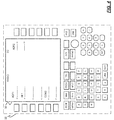
- FIGS. 2-4 illustrate an exemplary display system 16 that is implemented as a multi-control display unit (MCDU).
- the MCDU displays various pages 34-38 of information on the display device 22.
- the information displayed on the pages 34-38 is populated from information received from one or more of the systems 14a-14n.
- the pages 34-38 are displayed based on information requested by a user or pilot.
- the information is requested based on a user's selection of one or more of the input devices 24.
- the "ECON Cruise" page 34 is being displayed as shown in FIG. 2
- a user can select the "Radio" button input device 24a which results in the "PERF INDEX" page 36 to be displayed as shown in FIG. 3 .
- the "PERF INDEX" page 36 is displayed as shown in FIG. 3
- a user selects the "NEXT” button input device 24b the "RADIO” page 38 is displayed as shown in FIG. 4 .
- the data access module 30 of FIG. 1 makes use of the established relationship between the user selections and the data that is displayed on the pages as a result of the selection to access data from the systems 14a-14n. For example, the data access module 30 simulates certain user selections to cause one or more requests to be generated to one or more of the systems 14a-14n for the information. The data access module 30 simulates the user selections based on the page associated with the information that is requested and a communication protocol associated with the system 14a-14n in which the information is being requested from.
- a dataflow diagram illustrates the data access module 30 in more detail in accordance with various embodiments.
- various exemplary embodiments of the data access module 30, according to the present disclosure may include any number of sub-modules.
- the sub-modules shown in FIG. 5 may be combined and/or further partitioned to similarly access data from the systems 14a-14n and provide the data to new systems or applications 32.
- the data access module 30 includes a mode control module 40, a protocol determination module 42, a data communication module 44, and one or more datastores 46, 48.
- the mode control module 40 determines an operating mode of the display system 16 and generates a request 50 to change the current operating mode based on the determined operating mode.
- the various operating modes can include, but are not limited to a standard operating mode and a non-display operating mode. For example, when in the standard operating mode, the display system 16 displays information as the information is received. In another example, when in the non-display operating mode, the display system 16 maintains a current display of information and does not display any new information.
- the mode control module 40 determines the operating mode based on received inputs. For example, the mode control module 40 receives as input a start request 52. The start request 52 may be generated by a new system or application 32 that plans to request information. Based on the start request 52, the mode control module 40 determines the operating mode to be the non-display mode and generates the mode change request 50 to change the current mode to the determined non-display mode. The mode control module 40 then captures a snapshot 54 of the current page block displayed by the display system 16 and captures the current active system 56. The mode control module 40 stores the snapshot 54 and the active system 56 in a datastore 46 for future use.
- the mode control module 40 receives as input user selection data 58.
- the user selection data 58 may be generated based on a user's interaction with one or more input devices 24 of the display system 16.
- the mode control module 40 determines the operating mode to be a standard mode and if the current mode is not already the standard mode, generates a mode change request 50 to change the current mode to the determined standard mode.
- the mode control module 40 uses the stored snapshot 54 and the active system 56 to generate device restore data 60 to restore the page block and active system of the display system 16.
- the protocol determination module 42 receives as input information request data 62.
- the information request data 62 can be a part of the start request 52 or be part of a separate request.
- the information request data 62 can be generated by the new application that is requesting information.
- the protocol determination module 42 determines what information is requested.
- the protocol determination module 42 determines which page 64 (from any number of displayable pages) is associated with the information that is requested. For example, an association of the information to a particular displayable page 64 may be stored as a table in a datastore 48 and the page 64 may be looked up from the table based on the information.
- the protocol determination module 42 determines a protocol 66 to cause the page and/or a data element of the page 68 to be displayed.
- the protocol 66 can correspond to a simulation of certain input selections (e.g., button presses, or other selections) to cause the page 64 to be displayed.
- the protocol determination module 42 provides the protocol 66 and the page or data element 68 to the data communication module 44 for future use.
- the data communication module 44 receives as input the protocol 66 and the page or data element 68 to be requested.
- the data communication module 44 generates system requests 70 to the one or more of the system 14a-14n based on the received protocol 66 and the page or data element 68.
- the data communication module 44 receives information 72 based on the request.
- the data communication module 44 verifies the received information 72 to ensure that the information received corresponds to the information requested.
- the data communication module 44 communicates the received information 72 to the new system or application 32 as requested information data 74 based on the protocol established for the new system or application (e.g., which may be known or determined).
- FIG. 6 a flowchart illustrates a method 190 that can be performed by the data access module 30 in accordance with the present disclosure.
- the order of operation within the method is not limited to the sequential execution as illustrated in FIG. 6 , but may be performed in one or more varying orders as applicable and in accordance with the present disclosure.
- the method 190 may be scheduled to run based on predetermined events or may be scheduled to run at predetermined time intervals. In one example, the method may begin at 200. It is determined whether a start request 52 is received at 210. If a start request 52 is not received, the method 190 continues to monitor for a start request 52 at 210.
- the snapshot 54 is taken of a current page block and the active system 56 is determined at 220.
- the mode of the display system 16 is modified to the non-display mode where all received information or the requested information that is received is not displayed at 230.
- the page or data element of the page 68 that is associated with the information that is requested is determined at 250.
- the protocol 66 associated with the page and/or the particular data element of the page 68 is determined at 260.
- the system request 70 for the information is generated based on the protocol 66 at 270.
- the information Upon receipt of information from the system 14a-14n at 280, the information is verified at 290. If, the information is not the requested information at 300, optionally an error notification message is generated at 330 and the mode of the display system 16 is modified to the standard mode at 340. The snapshot captured at 220 is used to restore the display device 22 to the current page at 350. Thereafter, the method may end at 360.
- the information is the information that was requested at 300, then the information is communicated to the new system or application 32 at 310. If the non-display mode has not been ended at 320, the method continues to determine the information requested at 240. If, however, the non-display mode has been ended, for example, based on a user's interaction with the display system 16, the mode of the display system 16 is modified to a standard mode at 340. The snapshot 54 captured at 220 is used to restore the display device 22 to the current page at 350. Thereafter, the method may end at 360.
- Skilled artisans may implement the described functionality in varying ways for each particular application, but such implementation decisions should not be interpreted as causing a departure from the scope of the present invention.
- an embodiment of a system or a component may employ various integrated circuit components, e.g., memory elements, digital signal processing elements, logic elements, look-up tables, or the like, which may carry out a variety of functions under the control of one or more microprocessors or other control devices.
- integrated circuit components e.g., memory elements, digital signal processing elements, logic elements, look-up tables, or the like, which may carry out a variety of functions under the control of one or more microprocessors or other control devices.
- DSP digital signal processor
- ASIC application specific integrated circuit
- FPGA field programmable gate array
- a general-purpose processor may be a microprocessor, but in the alternative, the processor may be any conventional processor, controller, microcontroller, or state machine.
- a processor may also be implemented as a combination of computing devices, e.g., a combination of a DSP and a microprocessor, a plurality of microprocessors, one or more microprocessors in conjunction with a DSP core, or any other such configuration.
- a software module may reside in RAM memory, flash memory, ROM memory, EPROM memory, EEPROM memory, registers, hard disk, a removable disk, a CD-ROM, or any other form of storage medium known in the art.
- An exemplary storage medium is coupled to the processor such the processor can read information from, and write information to, the storage medium.
- the storage medium may be integral to the processor.
- the processor and the storage medium may reside in an ASIC.
- the ASIC may reside in a user terminal.
- the processor and the storage medium may reside as discrete components in a user terminal.
Landscapes
- Engineering & Computer Science (AREA)
- Theoretical Computer Science (AREA)
- General Engineering & Computer Science (AREA)
- Software Systems (AREA)
- Human Computer Interaction (AREA)
- Physics & Mathematics (AREA)
- General Physics & Mathematics (AREA)
- Computer Networks & Wireless Communication (AREA)
- Signal Processing (AREA)
- Health & Medical Sciences (AREA)
- Computing Systems (AREA)
- General Health & Medical Sciences (AREA)
- Medical Informatics (AREA)
- User Interface Of Digital Computer (AREA)
- Information Retrieval, Db Structures And Fs Structures Therefor (AREA)
Abstract
Description
- The present disclosure generally relates to methods and systems for accessing data of a system.
- An aircraft includes various hierarchically related sub-systems such as, propulsion systems, flight management systems, etc., that communicate over one or more networks. Legacy aircraft contain a defined set of systems and needed wiring to support the systems. In order to add functionality to a legacy aircraft, the system can be modified to add the functionality, or a new system can be added or provided in place of the existing system to add the functionality. For example, to add a new performance application, the flight management system (FMS) software must be modified. To add the display of the newly computed value on a displayed map, both the FMS software and display software must be modified. In another example, the new performance application could be added to a new system that would require an update to the wiring. Either option can be costly and or time consuming to add the new performance application.
- Hence, there is a need for improved methods and for integrating new applications in a legacy aircraft. In addition, there is a need for improved methods and systems for accessing data in any system. Other desirable features and characteristics will become apparent from the subsequent detailed description and the appended claims, taken in conjunction with the accompanying drawings and the foregoing technical field and background.
- Methods and systems are provided for accessing data in a networked system. In one embodiment, a method includes: receiving a request for information from a first system; evaluating a display system to determine a communication request to be generated to obtain the information; and generating a request to a second system based on the communication request.
- Furthermore, other desirable features and characteristics of the method and system will become apparent from the subsequent detailed description and the appended claims, taken in conjunction with the accompanying drawings and the preceding background.
- The present invention will hereinafter be described in conjunction with the following figures, wherein like numerals denote like elements, and wherein:
-
FIG. 1 is a functional block diagram illustrating an aircraft having a data access system in accordance with exemplary embodiments; -
FIGS. 2-4 are illustrations of a data access system of an aircraft in accordance with exemplary embodiments; -
FIG. 5 is a functional block diagram illustrating a data access module of the data access system in accordance with exemplary embodiments; and -
FIG. 6 is a flowchart illustrating a data access method that may be performed by the data access module in accordance with exemplary embodiments. - The following detailed description is merely exemplary in nature and is not intended to limit the disclosure or the application and uses of the disclosure. As used herein, the word "exemplary" means "serving as an example, instance, or illustration." Thus, any embodiment described herein as "exemplary" is not necessarily to be construed as preferred or advantageous over other embodiments. All of the embodiments described herein are exemplary embodiments provided to enable persons skilled in the art to make or use the invention and not to limit the scope of the invention which is defined by the claims. Furthermore, there is no intention to be bound by any expressed or implied theory presented in the preceding technical field, background, brief summary, or the following detailed description.
- As used herein, the term module refers to any hardware, software, firmware, electronic control component, processing logic, and/or processor device, individually or in any combination, including without limitation: application specific integrated circuit (ASIC), an electronic circuit, a processor (shared, dedicated, or group) and memory that executes one or more software or firmware programs, a combinational logic circuit, and/or other suitable components that provide the described functionality.
- Referring now to
FIG. 1 , exemplary embodiments of the present disclosure are directed to adata access system 10 that may be implemented, for example, on anaircraft 12. As can be appreciated, thedata access system 10 described herein can be implemented for networked systems (not shown) other than anaircraft 12. For exemplary purposes, the disclosure will be discussed in the context of thedata access system 10 and theaircraft 12. Although the figures shown herein depict an example with certain arrangements of elements, additional intervening elements, devices, features, or components may be present in actual embodiments. It should also be understood thatFIG. 1 is merely illustrative and may not be drawn to scale. - As shown in
Fig. 1 , theaircraft 12 generally includes one ormore aircraft systems 14a-14n that communicate with adisplay system 16 to display information about theaircraft 12 to a pilot or other user. Theaircraft systems 14a -14n include conventional systems of an aircraft such as, but not limited to, a flight management system, a cabin management system, control systems, etc. The communication between thesystems 14a-14n and thedisplay system 16 may be via acommunication bus 18 or other direct or indirect communication means. - The
display system 16 includes acomputing device 20, adisplay device 22, and one ormore input devices 24. Thedisplay device 22 may be located in a cockpit (not shown) of theaircraft 12 for viewing by, for example, a pilot of theaircraft 12. In various embodiments, thedisplay device 22 is an interactive display device (e.g., a touch screen, or other interactive display device) that accepts user input from a user through the one or more of theuser input devices 24. - The
computing device 20 includes at least aprocessor 26, and one or moredata storage devices 28. Theprocessor 26 can be any custom made or commercially available processor, a central processing unit (CPU), an auxiliary processor among several processors associated with thecomputing device 20, a semiconductor based microprocessor (in the form of a microchip or chip set), a macroprocessor, or generally any device for executing instructions. Thedata storage device 28 may be one or a combination of storage elements that store data, and/or instructions that can be performed by theprocessor 26. The instructions may include one or more separate programs, each of which comprises an ordered listing of executable instructions for implementing logical functions. - In various embodiments, the
data storage device 28 stores adata access module 30. In various embodiments, thedata access module 30 includes one or more instructions that may be executed by theprocessor 26 of thecomputing device 20. In general, the instructions of thedata access module 30 cause thedisplay system 16 to communicate with the one ormore systems 14a-14n of theaircraft 12 to obtain information. The instructions of thedata access module 30 further cause thedata access module 30 to receive the information and to provide the information to othernew systems 32 of theaircraft 12. For example, thedata access module 30 provides the information to anew system 32 or new application of anew system 32 or existingsystem 14a-14n requesting the information. Thedata access module 30 provides the information in a non-intrusive manner such that the hardware and/or the software of theaircraft systems 14a-14n and thedisplay system 16 do not have to be modified. - For example,
FIGS. 2-4 illustrate anexemplary display system 16 that is implemented as a multi-control display unit (MCDU). The MCDU displays various pages 34-38 of information on thedisplay device 22. The information displayed on the pages 34-38 is populated from information received from one or more of thesystems 14a-14n. The pages 34-38 are displayed based on information requested by a user or pilot. The information is requested based on a user's selection of one or more of theinput devices 24. For example, when the "ECON Cruise"page 34 is being displayed as shown inFIG. 2 , a user can select the "Radio"button input device 24a which results in the "PERF INDEX"page 36 to be displayed as shown inFIG. 3 . When the "PERF INDEX"page 36 is displayed as shown inFIG. 3 , and a user selects the "NEXT"button input device 24b, the "RADIO"page 38 is displayed as shown inFIG. 4 . - The
data access module 30 ofFIG. 1 makes use of the established relationship between the user selections and the data that is displayed on the pages as a result of the selection to access data from thesystems 14a-14n. For example, thedata access module 30 simulates certain user selections to cause one or more requests to be generated to one or more of thesystems 14a-14n for the information. Thedata access module 30 simulates the user selections based on the page associated with the information that is requested and a communication protocol associated with thesystem 14a-14n in which the information is being requested from. - Referring now to
FIG. 5 and with continued reference toFIG. 1 , a dataflow diagram illustrates thedata access module 30 in more detail in accordance with various embodiments. As can be appreciated, various exemplary embodiments of thedata access module 30, according to the present disclosure, may include any number of sub-modules. In various exemplary embodiments, the sub-modules shown inFIG. 5 may be combined and/or further partitioned to similarly access data from thesystems 14a-14n and provide the data to new systems orapplications 32. In various exemplary embodiments, thedata access module 30 includes amode control module 40, aprotocol determination module 42, adata communication module 44, and one ormore datastores - The
mode control module 40 determines an operating mode of thedisplay system 16 and generates arequest 50 to change the current operating mode based on the determined operating mode. In various embodiments, the various operating modes can include, but are not limited to a standard operating mode and a non-display operating mode. For example, when in the standard operating mode, thedisplay system 16 displays information as the information is received. In another example, when in the non-display operating mode, thedisplay system 16 maintains a current display of information and does not display any new information. - In various embodiments, the
mode control module 40 determines the operating mode based on received inputs. For example, themode control module 40 receives as input astart request 52. Thestart request 52 may be generated by a new system orapplication 32 that plans to request information. Based on thestart request 52, themode control module 40 determines the operating mode to be the non-display mode and generates themode change request 50 to change the current mode to the determined non-display mode. Themode control module 40 then captures asnapshot 54 of the current page block displayed by thedisplay system 16 and captures the currentactive system 56. Themode control module 40 stores thesnapshot 54 and theactive system 56 in adatastore 46 for future use. - In another example, the
mode control module 40 receives as inputuser selection data 58. Theuser selection data 58 may be generated based on a user's interaction with one ormore input devices 24 of thedisplay system 16. Based on theuser selection data 58, themode control module 40 determines the operating mode to be a standard mode and if the current mode is not already the standard mode, generates amode change request 50 to change the current mode to the determined standard mode. Themode control module 40 then uses the storedsnapshot 54 and theactive system 56 to generate device restoredata 60 to restore the page block and active system of thedisplay system 16. - The
protocol determination module 42 receives as inputinformation request data 62. In various embodiments, theinformation request data 62 can be a part of thestart request 52 or be part of a separate request. Theinformation request data 62 can be generated by the new application that is requesting information. Based on theinformation request data 62, theprotocol determination module 42 determines what information is requested. Theprotocol determination module 42 then determines which page 64 (from any number of displayable pages) is associated with the information that is requested. For example, an association of the information to a particulardisplayable page 64 may be stored as a table in adatastore 48 and thepage 64 may be looked up from the table based on the information. Theprotocol determination module 42 then determines aprotocol 66 to cause the page and/or a data element of thepage 68 to be displayed. For example, theprotocol 66 can correspond to a simulation of certain input selections (e.g., button presses, or other selections) to cause thepage 64 to be displayed. Theprotocol determination module 42 provides theprotocol 66 and the page ordata element 68 to thedata communication module 44 for future use. - The
data communication module 44 receives as input theprotocol 66 and the page ordata element 68 to be requested. Thedata communication module 44 generates system requests 70 to the one or more of thesystem 14a-14n based on the receivedprotocol 66 and the page ordata element 68. In response, thedata communication module 44 receivesinformation 72 based on the request. Optionally, thedata communication module 44 verifies the receivedinformation 72 to ensure that the information received corresponds to the information requested. Thedata communication module 44 communicates the receivedinformation 72 to the new system orapplication 32 as requestedinformation data 74 based on the protocol established for the new system or application (e.g., which may be known or determined). - Referring now to
FIG. 6 , and with continued reference toFIGS. 1 through 5 , a flowchart illustrates amethod 190 that can be performed by thedata access module 30 in accordance with the present disclosure. As can be appreciated in light of the disclosure, the order of operation within the method is not limited to the sequential execution as illustrated inFIG. 6 , but may be performed in one or more varying orders as applicable and in accordance with the present disclosure. - In various embodiments, the
method 190 may be scheduled to run based on predetermined events or may be scheduled to run at predetermined time intervals. In one example, the method may begin at 200. It is determined whether astart request 52 is received at 210. If astart request 52 is not received, themethod 190 continues to monitor for astart request 52 at 210. - If, however, a
start request 52 is received at 210, thesnapshot 54 is taken of a current page block and theactive system 56 is determined at 220. The mode of thedisplay system 16 is modified to the non-display mode where all received information or the requested information that is received is not displayed at 230. Thereafter, it is determined what information is requested at 240. For example, a subsequent request is received or the first request containing theinformation request data 62 is processed to determine the information that is requested at 240. The page or data element of thepage 68 that is associated with the information that is requested is determined at 250. Theprotocol 66 associated with the page and/or the particular data element of thepage 68 is determined at 260. Thereafter, thesystem request 70 for the information is generated based on theprotocol 66 at 270. - Upon receipt of information from the
system 14a-14n at 280, the information is verified at 290. If, the information is not the requested information at 300, optionally an error notification message is generated at 330 and the mode of thedisplay system 16 is modified to the standard mode at 340. The snapshot captured at 220 is used to restore thedisplay device 22 to the current page at 350. Thereafter, the method may end at 360. - If, however, the information is the information that was requested at 300, then the information is communicated to the new system or
application 32 at 310. If the non-display mode has not been ended at 320, the method continues to determine the information requested at 240. If, however, the non-display mode has been ended, for example, based on a user's interaction with thedisplay system 16, the mode of thedisplay system 16 is modified to a standard mode at 340. Thesnapshot 54 captured at 220 is used to restore thedisplay device 22 to the current page at 350. Thereafter, the method may end at 360. - Those of skill in the art will appreciate that the various illustrative logical blocks, modules, and algorithm steps described in connection with the embodiments disclosed herein may be implemented as electronic hardware, computer software, or combinations of both. Some of the embodiments and implementations are described above in terms of functional and/or logical block components (or modules) and various processing steps. However, it should be appreciated that such block components (or modules) may be realized by any number of hardware, software, and/or firmware components configured to perform the specified functions. To clearly illustrate this interchangeability of hardware and software, various illustrative components, blocks, modules, circuits, and steps have been described above generally in terms of their functionality. Whether such functionality is implemented as hardware or software depends upon the particular application and design constraints imposed on the overall system. Skilled artisans may implement the described functionality in varying ways for each particular application, but such implementation decisions should not be interpreted as causing a departure from the scope of the present invention. For example, an embodiment of a system or a component may employ various integrated circuit components, e.g., memory elements, digital signal processing elements, logic elements, look-up tables, or the like, which may carry out a variety of functions under the control of one or more microprocessors or other control devices. In addition, those skilled in the art will appreciate that embodiments described herein are merely exemplary implementations
- The various illustrative logical blocks, modules, and circuits described in connection with the embodiments disclosed herein may be implemented or performed with a general purpose processor, a digital signal processor (DSP), an application specific integrated circuit (ASIC), a field programmable gate array (FPGA) or other programmable logic device, discrete gate or transistor logic, discrete hardware components, or any combination thereof designed to perform the functions described herein. A general-purpose processor may be a microprocessor, but in the alternative, the processor may be any conventional processor, controller, microcontroller, or state machine. A processor may also be implemented as a combination of computing devices, e.g., a combination of a DSP and a microprocessor, a plurality of microprocessors, one or more microprocessors in conjunction with a DSP core, or any other such configuration.
- The steps of a method or algorithm described in connection with the embodiments disclosed herein may be embodied directly in hardware, in a software module executed by a processor, or in a combination of the two. A software module may reside in RAM memory, flash memory, ROM memory, EPROM memory, EEPROM memory, registers, hard disk, a removable disk, a CD-ROM, or any other form of storage medium known in the art. An exemplary storage medium is coupled to the processor such the processor can read information from, and write information to, the storage medium. In the alternative, the storage medium may be integral to the processor. The processor and the storage medium may reside in an ASIC. The ASIC may reside in a user terminal. In the alternative, the processor and the storage medium may reside as discrete components in a user terminal.
- In this document, relational terms such as first and second, and the like may be used solely to distinguish one entity or action from another entity or action without necessarily requiring or implying any actual such relationship or order between such entities or actions. Numerical ordinals such as "first", "second", "third", etc. simply denote different singles of a plurality and do not imply any order or sequence unless specifically defined by the claim language. The sequence of the text in any of the claims does not imply that process steps must be performed in a temporal or logical order according to such sequence unless it is specifically defined by the language of the claim. The process steps may be interchanged in any order without departing from the scope of the invention as long as such an interchange does not contradict the claim language and is not logically nonsensical.
- While at least one exemplary embodiment has been presented in the foregoing detailed description of the invention, it should be appreciated that a vast number of variations exist. It should also be appreciated that the exemplary embodiment or exemplary embodiments are only examples, and are not intended to limit the scope, applicability, or configuration of the invention in any way. Rather, the foregoing detailed description will provide those skilled in the art with a convenient road map for implementing an exemplary embodiment of the invention. It being understood that various changes may be made in the function and arrangement of elements described in an exemplary embodiment without departing from the scope of the invention as set forth in the appended claims.
Claims (9)
- A method of accessing data in a networked system, comprising:receiving a request for information from a first system;evaluating a display system to determine a communication request to be generated to obtain the information; andgenerating a request to a second system based on the communication request.
- The method of claim 1, wherein the evaluating comprises evaluating display page information to determine the communication request.
- The method of claim 1, further comprising determining a communication protocol based on the evaluating, and wherein the generating the request to the second system is based on the protocol.
- The method of claim 1, further comprising receiving information from the second system based on the request to the second system and providing the information to the first system.
- The method of claim 1, further comprising controlling an operating mode of the display system based on the request for information.
- The method of claim 5, further comprising controlling the operating mode of the display system based on a user selection.
- The method of claim 5, wherein the operating mode is at least one of a standard mode and a non-display mode.
- The method of claim 1, further comprising storing a snapshot of the display system based on the request for information.
- The method of claim 8, further comprising restoring the display system based on the snapshot.
Applications Claiming Priority (1)
| Application Number | Priority Date | Filing Date | Title |
|---|---|---|---|
| US14/850,020 US10254912B2 (en) | 2015-09-10 | 2015-09-10 | Methods and systems for non-intrusive system data pipe |
Publications (2)
| Publication Number | Publication Date |
|---|---|
| EP3142007A1 true EP3142007A1 (en) | 2017-03-15 |
| EP3142007B1 EP3142007B1 (en) | 2021-08-11 |
Family
ID=56943317
Family Applications (1)
| Application Number | Title | Priority Date | Filing Date |
|---|---|---|---|
| EP16187094.4A Active EP3142007B1 (en) | 2015-09-10 | 2016-09-02 | Methods and systems for non-intrusive system data pipe |
Country Status (3)
| Country | Link |
|---|---|
| US (1) | US10254912B2 (en) |
| EP (1) | EP3142007B1 (en) |
| CN (1) | CN106528091B (en) |
Citations (2)
| Publication number | Priority date | Publication date | Assignee | Title |
|---|---|---|---|---|
| US20050198580A1 (en) * | 2004-03-05 | 2005-09-08 | Morgan Hua | System and method for preventing screen-scrapers from extracting user screen names |
| WO2009086316A1 (en) * | 2007-12-21 | 2009-07-09 | Citrix Systems, Inc. | Systems and methods for efficient processing of data displayed by a window |
Family Cites Families (11)
| Publication number | Priority date | Publication date | Assignee | Title |
|---|---|---|---|---|
| US7716185B2 (en) * | 2005-06-29 | 2010-05-11 | Emc Corporation | Creation of a single client snapshot using a client utility |
| JP4793303B2 (en) * | 2007-03-29 | 2011-10-12 | ブラザー工業株式会社 | Data management system, information processing apparatus, and computer program |
| US8468263B2 (en) | 2008-02-18 | 2013-06-18 | The Boeing Company | Onboard network system architecture for improved communication and method of use |
| US8260800B2 (en) * | 2008-11-06 | 2012-09-04 | Nexplore Technolgies, Inc. | System and method for image generation, delivery, and management |
| US8855601B2 (en) * | 2009-02-17 | 2014-10-07 | Lookout, Inc. | System and method for remotely-initiated audio communication |
| US9141830B2 (en) | 2011-07-22 | 2015-09-22 | Aspen Avionics, Inc. | Avionics gateway interface, systems and methods |
| US8981968B2 (en) * | 2011-07-22 | 2015-03-17 | The Boeing Company | User-defined pages for aircraft |
| US8762990B2 (en) | 2011-07-25 | 2014-06-24 | The Boeing Company | Virtual machines for aircraft network data processing systems |
| GB2495079A (en) * | 2011-09-23 | 2013-04-03 | Hybrid Logic Ltd | Live migration of applications and file systems in a distributed system |
| US8965850B2 (en) * | 2011-11-18 | 2015-02-24 | Dell Software Inc. | Method of and system for merging, storing and retrieving incremental backup data |
| US8755953B2 (en) | 2012-05-21 | 2014-06-17 | The Boeing Company | Aircraft information management system |
-
2015
- 2015-09-10 US US14/850,020 patent/US10254912B2/en not_active Expired - Fee Related
-
2016
- 2016-09-02 EP EP16187094.4A patent/EP3142007B1/en active Active
- 2016-09-09 CN CN201610902407.2A patent/CN106528091B/en not_active Expired - Fee Related
Patent Citations (2)
| Publication number | Priority date | Publication date | Assignee | Title |
|---|---|---|---|---|
| US20050198580A1 (en) * | 2004-03-05 | 2005-09-08 | Morgan Hua | System and method for preventing screen-scrapers from extracting user screen names |
| WO2009086316A1 (en) * | 2007-12-21 | 2009-07-09 | Citrix Systems, Inc. | Systems and methods for efficient processing of data displayed by a window |
Also Published As
| Publication number | Publication date |
|---|---|
| CN106528091B (en) | 2021-06-08 |
| US20170075504A1 (en) | 2017-03-16 |
| US10254912B2 (en) | 2019-04-09 |
| CN106528091A (en) | 2017-03-22 |
| EP3142007B1 (en) | 2021-08-11 |
Similar Documents
| Publication | Publication Date | Title |
|---|---|---|
| US9014879B2 (en) | Messaging and data entry validation system and method for aircraft | |
| US10268515B2 (en) | Releasing resources from processes in a particular order to provide required resources to start an application | |
| DE112015003302B4 (en) | CONTROL OF MEDIA OUTPUT DURING SUBSEQUENT NAVIGATION INTERRUPTIONS | |
| US10606948B2 (en) | Predictive user interface for vehicle control system | |
| EP2903240B1 (en) | Method for communication | |
| US9176727B2 (en) | Infrastructure software patch reporting and analytics | |
| US11656634B2 (en) | Apparatus and method for providing enhanced autopilot mode awareness for a pilot of an aircraft | |
| US10065750B2 (en) | Aircraft maintenance systems and methods using wearable device | |
| CA2965283C (en) | Systems and methods of subject state change notification | |
| EP3021265A1 (en) | Context based content display in a wearable device | |
| US20250013638A1 (en) | Database-based data processing method, device, medium and apparatus | |
| US20130278628A1 (en) | Methods and systems for representing segmented circle airport marker information on a cockpit display | |
| EP2734814B1 (en) | User-defined pages for aircraft | |
| US10254912B2 (en) | Methods and systems for non-intrusive system data pipe | |
| US20160114901A1 (en) | Methods and systems for managing situation awareness information and alerts in a cockpit display | |
| KR101308022B1 (en) | A testing apparatus for a portable avionics system development and an operating method thereof | |
| US9889946B2 (en) | Electronic checklists with dynamic visibility of annotations | |
| US11769417B2 (en) | Methods and systems for representing flight mode annunciation information on a cockpit display | |
| CN116501516B (en) | Multi-map calling method, device, equipment and storage medium | |
| US20190236965A1 (en) | System and method for providing prioritized alternate approach procedures | |
| CN114071032A (en) | Large screen control method, device, equipment and storage medium | |
| EP3951323A1 (en) | Methods and systems for representing flight mode annunciation information on a cockpit display | |
| CN114827899B (en) | Parking fence range determination method, device and readable storage medium | |
| CN120892306A (en) | A correlation analysis method and apparatus for smart cockpit applications | |
| CN121704942A (en) | Vehicle-mounted user interface display method and device and vehicle |
Legal Events
| Date | Code | Title | Description |
|---|---|---|---|
| PUAI | Public reference made under article 153(3) epc to a published international application that has entered the european phase |
Free format text: ORIGINAL CODE: 0009012 |
|
| STAA | Information on the status of an ep patent application or granted ep patent |
Free format text: STATUS: REQUEST FOR EXAMINATION WAS MADE |
|
| 17P | Request for examination filed |
Effective date: 20160902 |
|
| AK | Designated contracting states |
Kind code of ref document: A1 Designated state(s): AL AT BE BG CH CY CZ DE DK EE ES FI FR GB GR HR HU IE IS IT LI LT LU LV MC MK MT NL NO PL PT RO RS SE SI SK SM TR |
|
| AX | Request for extension of the european patent |
Extension state: BA ME |
|
| STAA | Information on the status of an ep patent application or granted ep patent |
Free format text: STATUS: EXAMINATION IS IN PROGRESS |
|
| 17Q | First examination report despatched |
Effective date: 20180108 |
|
| REG | Reference to a national code |
Ref country code: DE Ref legal event code: R079 Ref document number: 602016061902 Country of ref document: DE Free format text: PREVIOUS MAIN CLASS: G06F0009440000 Ipc: G06F0009451000 |
|
| GRAJ | Information related to disapproval of communication of intention to grant by the applicant or resumption of examination proceedings by the epo deleted |
Free format text: ORIGINAL CODE: EPIDOSDIGR1 |
|
| STAA | Information on the status of an ep patent application or granted ep patent |
Free format text: STATUS: GRANT OF PATENT IS INTENDED |
|
| GRAP | Despatch of communication of intention to grant a patent |
Free format text: ORIGINAL CODE: EPIDOSNIGR1 |
|
| RIC1 | Information provided on ipc code assigned before grant |
Ipc: G06F 8/38 20180101ALI20210319BHEP Ipc: G06F 9/451 20180101AFI20210319BHEP |
|
| INTG | Intention to grant announced |
Effective date: 20210408 |
|
| RIN1 | Information on inventor provided before grant (corrected) |
Inventor name: TOEWS, PHILIP |
|
| GRAS | Grant fee paid |
Free format text: ORIGINAL CODE: EPIDOSNIGR3 |
|
| GRAA | (expected) grant |
Free format text: ORIGINAL CODE: 0009210 |
|
| STAA | Information on the status of an ep patent application or granted ep patent |
Free format text: STATUS: THE PATENT HAS BEEN GRANTED |
|
| AK | Designated contracting states |
Kind code of ref document: B1 Designated state(s): AL AT BE BG CH CY CZ DE DK EE ES FI FR GB GR HR HU IE IS IT LI LT LU LV MC MK MT NL NO PL PT RO RS SE SI SK SM TR |
|
| REG | Reference to a national code |
Ref country code: CH Ref legal event code: EP |
|
| REG | Reference to a national code |
Ref country code: DE Ref legal event code: R096 Ref document number: 602016061902 Country of ref document: DE |
|
| REG | Reference to a national code |
Ref country code: IE Ref legal event code: FG4D Ref country code: AT Ref legal event code: REF Ref document number: 1420068 Country of ref document: AT Kind code of ref document: T Effective date: 20210915 |
|
| PGFP | Annual fee paid to national office [announced via postgrant information from national office to epo] |
Ref country code: FR Payment date: 20210927 Year of fee payment: 6 |
|
| PGFP | Annual fee paid to national office [announced via postgrant information from national office to epo] |
Ref country code: GB Payment date: 20210927 Year of fee payment: 6 Ref country code: DE Payment date: 20210929 Year of fee payment: 6 |
|
| REG | Reference to a national code |
Ref country code: LT Ref legal event code: MG9D |
|
| REG | Reference to a national code |
Ref country code: NL Ref legal event code: MP Effective date: 20210811 |
|
| REG | Reference to a national code |
Ref country code: AT Ref legal event code: MK05 Ref document number: 1420068 Country of ref document: AT Kind code of ref document: T Effective date: 20210811 |
|
| PG25 | Lapsed in a contracting state [announced via postgrant information from national office to epo] |
Ref country code: HR Free format text: LAPSE BECAUSE OF FAILURE TO SUBMIT A TRANSLATION OF THE DESCRIPTION OR TO PAY THE FEE WITHIN THE PRESCRIBED TIME-LIMIT Effective date: 20210811 Ref country code: RS Free format text: LAPSE BECAUSE OF FAILURE TO SUBMIT A TRANSLATION OF THE DESCRIPTION OR TO PAY THE FEE WITHIN THE PRESCRIBED TIME-LIMIT Effective date: 20210811 Ref country code: SE Free format text: LAPSE BECAUSE OF FAILURE TO SUBMIT A TRANSLATION OF THE DESCRIPTION OR TO PAY THE FEE WITHIN THE PRESCRIBED TIME-LIMIT Effective date: 20210811 Ref country code: NO Free format text: LAPSE BECAUSE OF FAILURE TO SUBMIT A TRANSLATION OF THE DESCRIPTION OR TO PAY THE FEE WITHIN THE PRESCRIBED TIME-LIMIT Effective date: 20211111 Ref country code: PT Free format text: LAPSE BECAUSE OF FAILURE TO SUBMIT A TRANSLATION OF THE DESCRIPTION OR TO PAY THE FEE WITHIN THE PRESCRIBED TIME-LIMIT Effective date: 20211213 Ref country code: ES Free format text: LAPSE BECAUSE OF FAILURE TO SUBMIT A TRANSLATION OF THE DESCRIPTION OR TO PAY THE FEE WITHIN THE PRESCRIBED TIME-LIMIT Effective date: 20210811 Ref country code: FI Free format text: LAPSE BECAUSE OF FAILURE TO SUBMIT A TRANSLATION OF THE DESCRIPTION OR TO PAY THE FEE WITHIN THE PRESCRIBED TIME-LIMIT Effective date: 20210811 Ref country code: LT Free format text: LAPSE BECAUSE OF FAILURE TO SUBMIT A TRANSLATION OF THE DESCRIPTION OR TO PAY THE FEE WITHIN THE PRESCRIBED TIME-LIMIT Effective date: 20210811 Ref country code: BG Free format text: LAPSE BECAUSE OF FAILURE TO SUBMIT A TRANSLATION OF THE DESCRIPTION OR TO PAY THE FEE WITHIN THE PRESCRIBED TIME-LIMIT Effective date: 20211111 Ref country code: AT Free format text: LAPSE BECAUSE OF FAILURE TO SUBMIT A TRANSLATION OF THE DESCRIPTION OR TO PAY THE FEE WITHIN THE PRESCRIBED TIME-LIMIT Effective date: 20210811 |
|
| PG25 | Lapsed in a contracting state [announced via postgrant information from national office to epo] |
Ref country code: PL Free format text: LAPSE BECAUSE OF FAILURE TO SUBMIT A TRANSLATION OF THE DESCRIPTION OR TO PAY THE FEE WITHIN THE PRESCRIBED TIME-LIMIT Effective date: 20210811 Ref country code: LV Free format text: LAPSE BECAUSE OF FAILURE TO SUBMIT A TRANSLATION OF THE DESCRIPTION OR TO PAY THE FEE WITHIN THE PRESCRIBED TIME-LIMIT Effective date: 20210811 Ref country code: GR Free format text: LAPSE BECAUSE OF FAILURE TO SUBMIT A TRANSLATION OF THE DESCRIPTION OR TO PAY THE FEE WITHIN THE PRESCRIBED TIME-LIMIT Effective date: 20211112 |
|
| PG25 | Lapsed in a contracting state [announced via postgrant information from national office to epo] |
Ref country code: NL Free format text: LAPSE BECAUSE OF FAILURE TO SUBMIT A TRANSLATION OF THE DESCRIPTION OR TO PAY THE FEE WITHIN THE PRESCRIBED TIME-LIMIT Effective date: 20210811 |
|
| PG25 | Lapsed in a contracting state [announced via postgrant information from national office to epo] |
Ref country code: DK Free format text: LAPSE BECAUSE OF FAILURE TO SUBMIT A TRANSLATION OF THE DESCRIPTION OR TO PAY THE FEE WITHIN THE PRESCRIBED TIME-LIMIT Effective date: 20210811 |
|
| REG | Reference to a national code |
Ref country code: CH Ref legal event code: PL |
|
| REG | Reference to a national code |
Ref country code: DE Ref legal event code: R097 Ref document number: 602016061902 Country of ref document: DE |
|
| REG | Reference to a national code |
Ref country code: BE Ref legal event code: MM Effective date: 20210930 |
|
| PG25 | Lapsed in a contracting state [announced via postgrant information from national office to epo] |
Ref country code: SM Free format text: LAPSE BECAUSE OF FAILURE TO SUBMIT A TRANSLATION OF THE DESCRIPTION OR TO PAY THE FEE WITHIN THE PRESCRIBED TIME-LIMIT Effective date: 20210811 Ref country code: SK Free format text: LAPSE BECAUSE OF FAILURE TO SUBMIT A TRANSLATION OF THE DESCRIPTION OR TO PAY THE FEE WITHIN THE PRESCRIBED TIME-LIMIT Effective date: 20210811 Ref country code: RO Free format text: LAPSE BECAUSE OF FAILURE TO SUBMIT A TRANSLATION OF THE DESCRIPTION OR TO PAY THE FEE WITHIN THE PRESCRIBED TIME-LIMIT Effective date: 20210811 Ref country code: MC Free format text: LAPSE BECAUSE OF FAILURE TO SUBMIT A TRANSLATION OF THE DESCRIPTION OR TO PAY THE FEE WITHIN THE PRESCRIBED TIME-LIMIT Effective date: 20210811 Ref country code: EE Free format text: LAPSE BECAUSE OF FAILURE TO SUBMIT A TRANSLATION OF THE DESCRIPTION OR TO PAY THE FEE WITHIN THE PRESCRIBED TIME-LIMIT Effective date: 20210811 Ref country code: CZ Free format text: LAPSE BECAUSE OF FAILURE TO SUBMIT A TRANSLATION OF THE DESCRIPTION OR TO PAY THE FEE WITHIN THE PRESCRIBED TIME-LIMIT Effective date: 20210811 Ref country code: AL Free format text: LAPSE BECAUSE OF FAILURE TO SUBMIT A TRANSLATION OF THE DESCRIPTION OR TO PAY THE FEE WITHIN THE PRESCRIBED TIME-LIMIT Effective date: 20210811 |
|
| PLBE | No opposition filed within time limit |
Free format text: ORIGINAL CODE: 0009261 |
|
| STAA | Information on the status of an ep patent application or granted ep patent |
Free format text: STATUS: NO OPPOSITION FILED WITHIN TIME LIMIT |
|
| 26N | No opposition filed |
Effective date: 20220512 |
|
| PG25 | Lapsed in a contracting state [announced via postgrant information from national office to epo] |
Ref country code: LU Free format text: LAPSE BECAUSE OF NON-PAYMENT OF DUE FEES Effective date: 20210902 Ref country code: IT Free format text: LAPSE BECAUSE OF FAILURE TO SUBMIT A TRANSLATION OF THE DESCRIPTION OR TO PAY THE FEE WITHIN THE PRESCRIBED TIME-LIMIT Effective date: 20210811 Ref country code: IE Free format text: LAPSE BECAUSE OF NON-PAYMENT OF DUE FEES Effective date: 20210902 Ref country code: BE Free format text: LAPSE BECAUSE OF NON-PAYMENT OF DUE FEES Effective date: 20210930 |
|
| PG25 | Lapsed in a contracting state [announced via postgrant information from national office to epo] |
Ref country code: SI Free format text: LAPSE BECAUSE OF FAILURE TO SUBMIT A TRANSLATION OF THE DESCRIPTION OR TO PAY THE FEE WITHIN THE PRESCRIBED TIME-LIMIT Effective date: 20210811 Ref country code: LI Free format text: LAPSE BECAUSE OF NON-PAYMENT OF DUE FEES Effective date: 20210930 Ref country code: CH Free format text: LAPSE BECAUSE OF NON-PAYMENT OF DUE FEES Effective date: 20210930 |
|
| REG | Reference to a national code |
Ref country code: DE Ref legal event code: R119 Ref document number: 602016061902 Country of ref document: DE |
|
| GBPC | Gb: european patent ceased through non-payment of renewal fee |
Effective date: 20220902 |
|
| PG25 | Lapsed in a contracting state [announced via postgrant information from national office to epo] |
Ref country code: HU Free format text: LAPSE BECAUSE OF FAILURE TO SUBMIT A TRANSLATION OF THE DESCRIPTION OR TO PAY THE FEE WITHIN THE PRESCRIBED TIME-LIMIT; INVALID AB INITIO Effective date: 20160902 |
|
| PG25 | Lapsed in a contracting state [announced via postgrant information from national office to epo] |
Ref country code: CY Free format text: LAPSE BECAUSE OF FAILURE TO SUBMIT A TRANSLATION OF THE DESCRIPTION OR TO PAY THE FEE WITHIN THE PRESCRIBED TIME-LIMIT Effective date: 20210811 |
|
| P01 | Opt-out of the competence of the unified patent court (upc) registered |
Effective date: 20230525 |
|
| PG25 | Lapsed in a contracting state [announced via postgrant information from national office to epo] |
Ref country code: FR Free format text: LAPSE BECAUSE OF NON-PAYMENT OF DUE FEES Effective date: 20220930 Ref country code: DE Free format text: LAPSE BECAUSE OF NON-PAYMENT OF DUE FEES Effective date: 20230401 |
|
| PG25 | Lapsed in a contracting state [announced via postgrant information from national office to epo] |
Ref country code: GB Free format text: LAPSE BECAUSE OF NON-PAYMENT OF DUE FEES Effective date: 20220902 |
|
| PG25 | Lapsed in a contracting state [announced via postgrant information from national office to epo] |
Ref country code: MK Free format text: LAPSE BECAUSE OF FAILURE TO SUBMIT A TRANSLATION OF THE DESCRIPTION OR TO PAY THE FEE WITHIN THE PRESCRIBED TIME-LIMIT Effective date: 20210811 |
|
| PG25 | Lapsed in a contracting state [announced via postgrant information from national office to epo] |
Ref country code: TR Free format text: LAPSE BECAUSE OF FAILURE TO SUBMIT A TRANSLATION OF THE DESCRIPTION OR TO PAY THE FEE WITHIN THE PRESCRIBED TIME-LIMIT Effective date: 20210811 |
|
| PG25 | Lapsed in a contracting state [announced via postgrant information from national office to epo] |
Ref country code: MT Free format text: LAPSE BECAUSE OF FAILURE TO SUBMIT A TRANSLATION OF THE DESCRIPTION OR TO PAY THE FEE WITHIN THE PRESCRIBED TIME-LIMIT Effective date: 20210811 |