EP3141892A1 - Endoscope reprocessor - Google Patents
Endoscope reprocessor Download PDFInfo
- Publication number
- EP3141892A1 EP3141892A1 EP16801943.8A EP16801943A EP3141892A1 EP 3141892 A1 EP3141892 A1 EP 3141892A1 EP 16801943 A EP16801943 A EP 16801943A EP 3141892 A1 EP3141892 A1 EP 3141892A1
- Authority
- EP
- European Patent Office
- Prior art keywords
- medicinal
- section
- solution
- liquid
- endoscope reprocessor
- Prior art date
- Legal status (The legal status is an assumption and is not a legal conclusion. Google has not performed a legal analysis and makes no representation as to the accuracy of the status listed.)
- Withdrawn
Links
Images






Classifications
-
- A—HUMAN NECESSITIES
- A61—MEDICAL OR VETERINARY SCIENCE; HYGIENE
- A61B—DIAGNOSIS; SURGERY; IDENTIFICATION
- A61B1/00—Instruments for performing medical examinations of the interior of cavities or tubes of the body by visual or photographical inspection, e.g. endoscopes; Illuminating arrangements therefor
- A61B1/12—Instruments for performing medical examinations of the interior of cavities or tubes of the body by visual or photographical inspection, e.g. endoscopes; Illuminating arrangements therefor with cooling or rinsing arrangements
- A61B1/121—Instruments for performing medical examinations of the interior of cavities or tubes of the body by visual or photographical inspection, e.g. endoscopes; Illuminating arrangements therefor with cooling or rinsing arrangements provided with means for cleaning post-use
- A61B1/123—Instruments for performing medical examinations of the interior of cavities or tubes of the body by visual or photographical inspection, e.g. endoscopes; Illuminating arrangements therefor with cooling or rinsing arrangements provided with means for cleaning post-use using washing machines
-
- A—HUMAN NECESSITIES
- A61—MEDICAL OR VETERINARY SCIENCE; HYGIENE
- A61B—DIAGNOSIS; SURGERY; IDENTIFICATION
- A61B1/00—Instruments for performing medical examinations of the interior of cavities or tubes of the body by visual or photographical inspection, e.g. endoscopes; Illuminating arrangements therefor
- A61B1/12—Instruments for performing medical examinations of the interior of cavities or tubes of the body by visual or photographical inspection, e.g. endoscopes; Illuminating arrangements therefor with cooling or rinsing arrangements
-
- A—HUMAN NECESSITIES
- A61—MEDICAL OR VETERINARY SCIENCE; HYGIENE
- A61L—METHODS OR APPARATUS FOR STERILISING MATERIALS OR OBJECTS IN GENERAL; DISINFECTION, STERILISATION OR DEODORISATION OF AIR; CHEMICAL ASPECTS OF BANDAGES, DRESSINGS, ABSORBENT PADS OR SURGICAL ARTICLES; MATERIALS FOR BANDAGES, DRESSINGS, ABSORBENT PADS OR SURGICAL ARTICLES
- A61L2/00—Disinfection or sterilisation of materials or objects, in general; Accessories therefor
- A61L2/16—Disinfection or sterilisation of materials or objects, in general; Accessories therefor using chemical substances
- A61L2/18—Liquid substances
-
- B—PERFORMING OPERATIONS; TRANSPORTING
- B08—CLEANING
- B08B—CLEANING IN GENERAL; PREVENTION OF FOULING IN GENERAL
- B08B3/00—Cleaning by methods involving the use or presence of liquid or steam
- B08B3/04—Cleaning involving contact with liquid
-
- B—PERFORMING OPERATIONS; TRANSPORTING
- B08—CLEANING
- B08B—CLEANING IN GENERAL; PREVENTION OF FOULING IN GENERAL
- B08B9/00—Cleaning hollow articles by methods or apparatus specially adapted thereto
- B08B9/02—Cleaning pipes or tubes or systems of pipes or tubes
-
- G—PHYSICS
- G01—MEASURING; TESTING
- G01N—INVESTIGATING OR ANALYSING MATERIALS BY DETERMINING THEIR CHEMICAL OR PHYSICAL PROPERTIES
- G01N27/00—Investigating or analysing materials by the use of electric, electrochemical, or magnetic means
- G01N27/26—Investigating or analysing materials by the use of electric, electrochemical, or magnetic means by investigating electrochemical variables; by using electrolysis or electrophoresis
-
- G—PHYSICS
- G01—MEASURING; TESTING
- G01N—INVESTIGATING OR ANALYSING MATERIALS BY DETERMINING THEIR CHEMICAL OR PHYSICAL PROPERTIES
- G01N27/00—Investigating or analysing materials by the use of electric, electrochemical, or magnetic means
- G01N27/26—Investigating or analysing materials by the use of electric, electrochemical, or magnetic means by investigating electrochemical variables; by using electrolysis or electrophoresis
- G01N27/28—Electrolytic cell components
- G01N27/30—Electrodes, e.g. test electrodes; Half-cells
- G01N27/333—Ion-selective electrodes or membranes
-
- G—PHYSICS
- G01—MEASURING; TESTING
- G01N—INVESTIGATING OR ANALYSING MATERIALS BY DETERMINING THEIR CHEMICAL OR PHYSICAL PROPERTIES
- G01N27/00—Investigating or analysing materials by the use of electric, electrochemical, or magnetic means
- G01N27/26—Investigating or analysing materials by the use of electric, electrochemical, or magnetic means by investigating electrochemical variables; by using electrolysis or electrophoresis
- G01N27/403—Cells and electrode assemblies
- G01N27/404—Cells with anode, cathode and cell electrolyte on the same side of a permeable membrane which separates them from the sample fluid, e.g. Clark-type oxygen sensors
-
- G—PHYSICS
- G01—MEASURING; TESTING
- G01N—INVESTIGATING OR ANALYSING MATERIALS BY DETERMINING THEIR CHEMICAL OR PHYSICAL PROPERTIES
- G01N27/00—Investigating or analysing materials by the use of electric, electrochemical, or magnetic means
- G01N27/26—Investigating or analysing materials by the use of electric, electrochemical, or magnetic means by investigating electrochemical variables; by using electrolysis or electrophoresis
- G01N27/416—Systems
-
- A—HUMAN NECESSITIES
- A61—MEDICAL OR VETERINARY SCIENCE; HYGIENE
- A61L—METHODS OR APPARATUS FOR STERILISING MATERIALS OR OBJECTS IN GENERAL; DISINFECTION, STERILISATION OR DEODORISATION OF AIR; CHEMICAL ASPECTS OF BANDAGES, DRESSINGS, ABSORBENT PADS OR SURGICAL ARTICLES; MATERIALS FOR BANDAGES, DRESSINGS, ABSORBENT PADS OR SURGICAL ARTICLES
- A61L2103/00—Materials or objects being the target of disinfection or sterilisation
- A61L2103/15—Laboratory, medical or dentistry appliances, e.g. catheters or sharps
-
- A—HUMAN NECESSITIES
- A61—MEDICAL OR VETERINARY SCIENCE; HYGIENE
- A61L—METHODS OR APPARATUS FOR STERILISING MATERIALS OR OBJECTS IN GENERAL; DISINFECTION, STERILISATION OR DEODORISATION OF AIR; CHEMICAL ASPECTS OF BANDAGES, DRESSINGS, ABSORBENT PADS OR SURGICAL ARTICLES; MATERIALS FOR BANDAGES, DRESSINGS, ABSORBENT PADS OR SURGICAL ARTICLES
- A61L2202/00—Aspects relating to methods or apparatus for disinfecting or sterilising materials or objects
- A61L2202/10—Apparatus features
- A61L2202/14—Means for controlling sterilisation processes, data processing, presentation and storage means, e.g. sensors, controllers, programs
-
- A—HUMAN NECESSITIES
- A61—MEDICAL OR VETERINARY SCIENCE; HYGIENE
- A61L—METHODS OR APPARATUS FOR STERILISING MATERIALS OR OBJECTS IN GENERAL; DISINFECTION, STERILISATION OR DEODORISATION OF AIR; CHEMICAL ASPECTS OF BANDAGES, DRESSINGS, ABSORBENT PADS OR SURGICAL ARTICLES; MATERIALS FOR BANDAGES, DRESSINGS, ABSORBENT PADS OR SURGICAL ARTICLES
- A61L2202/00—Aspects relating to methods or apparatus for disinfecting or sterilising materials or objects
- A61L2202/10—Apparatus features
- A61L2202/15—Biocide distribution means, e.g. nozzles, pumps, manifolds, fans, baffles, sprayers
Definitions
- the present invention relates to an endoscope reprocessor that applies reprocessing, in which a medicinal solution is used, to an endoscope.
- An endoscope used in a medical field is subjected to reprocessing such as cleaning treatment and disinfecting treatment after use.
- An endoscope reprocessor that automatically performs the reprocessing of the endoscope is known.
- the endoscope reprocessor includes a medicinal solution tank that stores a medicinal solution used for the reprocessing.
- a concentration meter for measuring concentration of the medicinal solution disclosed in, for example, Japanese Patent Application Laid-Open Publication No. 2006-126046 is sometimes used.
- a concentration meter When a measurement surface that comes into contact with a medicinal solution during concentration measurement is in a dried state, a concentration meter needs a longer standby time period until a correct measurement result can be obtained after the measurement surface comes into contact with the medicinal solution compared with when the measurement surface is in a wet state.
- moisture retention of the measurement surface is performed by pressing the measurement surface against a sponge-like porous material wet by preservation liquid.
- a measurement surface sometimes is not instantaneously brought into a measurable wet state simply by pressing the measurement surface against the sponge-like porous material wet by the preservation liquid as in the concentration meter disclosed in Japanese Patent Application Laid-Open Publication No. 2006-126046 . That is, it is likely that a standby time period occurs before concentration measurement of the medicinal solution by the concentration meter is started.
- the present invention solves the problems explained above, and an object of the present invention is to provide an endoscope reprocessor that keeps a measurement surface of a concentration meter in a sufficient wet state.
- An endoscope reprocessor includes: a concentration meter including a housing, an electrode housed in the housing, a permeation membrane held by the housing, and internal liquid encapsulated in the housing, the concentration meter measuring concentration of a medicinal solution; a medicinal-solution storing section including a holding section configured to hold the concentration meter such that the permeation membrane is disposed at a predetermined water level, the medicinal-solution storing section storing the medicinal solution to a water level higher than the predetermined water level; a liquid discharge section configured to discharge the medicinal solution from the medicinal-solution storing section; a liquid supply section configured to supply liquid to the permeation membrane of the concentration meter; and a control section connected to the liquid discharge section and the liquid supply section, the control section driving the liquid supply section to wet the permeation membrane when the medicinal solution in the medicinal-solution storing section is lower than the predetermined water level.
- An endoscope reprocessor 1 shown in Fig. 1 is an apparatus that applies reprocessing to an endoscope.
- the reprocessing referred to herein is not particularly limited and may be any one of rinsing treatment by water, cleaning treatment for removing strains of organic matters and the like, disinfecting treatment for disabling predetermined microorganisms, sterilizing treatment for eliminating or killing all microorganisms, and a combination of the foregoing.
- upward indicates a position further away from a ground with respect to a comparison target and downward indicates a position closer to the ground with respect to the comparison target.
- High and low in the following explanation indicate a height relation along a gravity direction.
- the endoscope reprocessor 1 includes a control section 5, a power supply section 6, a treatment tank 2, a medicinal-solution storing section 20, a concentration meter 80, a liquid discharge section 28, and a liquid supply section 60.
- the control section 5 can include an arithmetic unit (a CPU), a storage device (a RAM), an auxiliary storage device, an input/output device, a power control device and the like.
- the control section 5 includes a configuration for controlling, based on a predetermined program, operations of respective parts configuring the endoscope reprocessor 1. Operations of the respective components included in the endoscope reprocessor 1 in the following explanation are controlled by the control section 5 even when not particularly described.
- the power supply section 6 supplies electric power to the respective parts of the endoscope reprocessor 1.
- the power supply section 6 distributes electric power obtained from an outside such as a commercial power supply to the respective parts.
- the power supply section 6 may include a power generating device or a battery.
- the treatment tank 2 is formed in a concave shape including an opening section and is capable of storing liquid inside.
- a not-shown endoscope can be disposed in the treatment tank 2.
- a lid 3 for opening and closing the opening section of the treatment tank 2 is provided in an upper part of the treatment tank 2. When reprocessing is applied to the endoscope in the treatment tank 2, the opening section of the treatment tank 2 is closed by the lid 3.
- a medicinal solution nozzle 12 In the treatment tank 2, a medicinal solution nozzle 12, a liquid discharge port 11, a circulation port 13, a circulation nozzle 14, a cleaning liquid nozzle 15, an endoscope connecting section 16, and an accessory case 17 are provided.
- the medicinal solution nozzle 12 is an opening section that communicates with the medicinal-solution storing section 20 via a medicinal solution conduit 26.
- the medicinal-solution storing section 20 stores a medicinal solution.
- a type of the medicinal solution stored by the medicinal-solution storing section 20 is not particularly limited.
- the medicinal solution is disinfectant liquid such as acetic peracid used for the disinfecting treatment.
- the present invention is not limited to this.
- cleaning liquid used for the cleaning treatment, a high-volatile solution used for drying, and the like can be selected as appropriate according to purposes.
- the medicinal solution is obtained by diluting, with water, at a predetermined ratio, a stock solution of the medicinal solution supplied from a medicinal solution bottle 18.
- the medicinal-solution storing section 20 of the present embodiment communicates with a bottle connecting section 19 that introduces the stock solution of the medicinal solution supplied from the medicinal solution bottle 18 into the medicinal-solution storing section 20 and a dilution conduit 48 for introducing water for dilution into the medicinal-solution storing section 20.
- the medicinal solution bottle 18 is connected to the bottle connecting section 19, whereby the stock solution of the medicinal solution is introduced into the medicinal-solution storing section 20.
- a configuration for introducing the water from the dilution conduit 48 into the medicinal-solution storing section 20 is explained below.
- the endoscope reprocessor 1 does not have to include the configuration for diluting the medicinal solution with the water or the like.
- the bottle connecting section 19 is connectable to a plurality of medicinal solution bottles 18.
- the medicinal solution is usable when concentration is within a predetermined range in which the medicinal solution has medicinal effects.
- the medicinal-solution storing section 20 stores the entire medicinal solution in the endoscope reprocessor 1. That is, in the present embodiment, the medicinal-solution storing section 20 also functions as a medicinal-solution collecting section 29 that collects and stores the medicinal solution in the endoscope reprocessor 1.
- the medicinal-solution storing section 20 and the medicinal-solution collecting section 29 are simply referred to as medicinal-solution storing section 20.
- the medicinal-solution storing section 20 may be provided separately from the medicinal-solution collecting section 29.
- the capacity of the medicinal-solution storing section 20 may be smaller than the capacity of the medicinal-solution collecting section 29.
- the concentration meter 80, the liquid discharge section 28, and the liquid supply section 60 are also disposed. Detailed configurations of these components and the medicinal-solution storing section 20 are explained below.
- a medicinal solution pump 27 is provided in the medicinal solution conduit 26. By operating the medicinal solution pump 27, the medicinal solution in the medicinal-solution storing section 20 is transferred into the treatment tank 2 through the medicinal solution conduit 26 and the medicinal solution nozzle 12.
- the liquid discharge port 11 is an opening section provided in a lowest part in the treatment tank 2.
- the liquid discharge port 11 is connected to a discharge conduit 21.
- the discharge conduit 21 causes the liquid discharge port 11 and a switching valve 22 to communicate.
- a collection conduit 23 and a discarding conduit 25 are connected to the switching valve 22.
- the switching valve 22 can be switched to a state in which the discharge conduit 21 is closed, a state in which the discharge conduit 21 and the collection conduit 23 are caused to communicate, or a state in which the discharge conduit 21 and the discarding conduit 25 are caused to communicate.
- the collection conduit 23 causes the medicinal-solution storing section 20 and the switching valve 22 to communicate.
- a discharge pump 24 is provided in the discarding conduit 25.
- the discarding conduit 25 is connected to a liquid discharge facility for receiving the liquid discharged from the endoscope reprocessor 1.
- the switching valve 22 is switched to a closed state, it is possible to store the liquid in the treatment tank 2.
- the medicinal solution is stored in the treatment tank 2
- the switching valve 22 is switched to the state in which the discharge conduit 21 and the collection conduit 23 communicate, the medicinal solution is transferred from the treatment tank 2 to the medicinal-solution storing section 20.
- the switching valve 22 is switched to the state in which the discharge conduit 21 and the discarding conduit 25 communicate and the operation of the discharge pump 24 is started, the liquid in the treatment tank 2 is delivered to the liquid discharge facility through the discarding conduit 25.
- the circulation port 13 is an opening section provided near a bottom surface of the treatment tank 2.
- the circulation port 13 communicates with a circulation conduit 13a.
- the circulation conduit 13a branches to two conduits of an endoscope circulation conduit 30 and a treatment tank circulation conduit 40.
- the endoscope circulation conduit 30 causes the circulation conduit 13a and a channel valve 32 explained below to communicate.
- a circulation pump 33 is provided in the endoscope circulation conduit 30. The circulation pump 33 operates to transfer fluid in the endoscope circulation conduit 30 toward the channel valve 32.
- an air intake conduit 34, an alcohol conduit 38, and a delivery conduit 31 are connected to the channel valve 32.
- the channel valve 32 selectively causes any one of the endoscope circulation conduit 30, the air intake conduit 34, and the alcohol conduit 38 to communicate with the delivery conduit 31.
- One end portion of the air intake conduit 34 is opened to an atmosphere.
- the other end portion is connected to the channel valve 32.
- a filter for filtering passing gas is provided at the one end portion of the air intake conduit 34.
- An air pump 35 is provided in the air intake conduit 34. The air pump 35 operates to thereby transfer the gas in the air intake conduit 34 toward the channel valve 32.
- the alcohol conduit 38 causes an alcohol tank 37 that stores alcohol and the channel valve 32 to communicate. Examples of the alcohol stored in the alcohol tank 37 include ethanol. Alcohol concentration can be selected as appropriate.
- An alcohol pump 39 is provided in the alcohol conduit 38. The alcohol pump 39 operates to thereby transfer the alcohol in the alcohol tank 37 toward the channel valve 32.
- the channel valve 32 is switched to a state in which the delivery conduit 31 and the air intake conduit 34 communicate and operation of the air pump 35 is started, the air is sent into the delivery conduit 31. If the channel valve 32 is switched to a state in which the delivery conduit 31 and the alcohol conduit 38 communicate and operation of the alcohol pump 39 is started, the alcohol in the alcohol tank 37 is sent into the delivery conduit 31.
- the delivery conduit 31 branches to an endoscope connection conduit 31b and a case connection conduit 31c.
- the endoscope connection conduit 31b is connected to the endoscope connecting section 16.
- the case connection conduit 31c is connected to the accessory case 17.
- a channel switching section 31 a is provided in the delivery conduit 31.
- the channel switching section 31a is capable of switching to which of the endoscope connection conduit 31b and the case connection conduit 31c the fluid sent into the delivery conduit 31 from the channel valve 32 is fed. Note that pressure on the endoscope connection conduit 31b side may be controlled to be constant during the switching.
- the endoscope connecting section 16 is connected to a pipe sleeve provided in the endoscope via a not-shown endoscope tube.
- the accessory case 17 is a basket-like member that houses not-shown accessories of the endoscope. Therefore, the fluid sent into the delivery conduit 31 from the channel valve 32 is introduced into the pipe sleeve of the endoscope or into the accessory case 17.
- the treatment tank circulation conduit 40 causes the circulation conduit 13a and the circulation nozzle 14 to communicate.
- the circulation nozzle 14 is an opening section provided in the treatment tank 2.
- a circulation pump 41 is provided in the treatment tank circulation conduit 40.
- a three-way valve 42 is provided between the circulation pump 41 of the treatment tank circulation conduit 40 and the circulation nozzle 14.
- a water supply conduit 43 is connected to the three-way valve 42.
- the three-way valve 42 can be switched to a state in which the circulation nozzle 14 and the treatment tank circulation conduit 40 are caused to communicate or a state in which the circulation nozzle 14 and the water supply conduit 43 are caused to communicate.
- the water supply conduit 43 causes the three-way valve 42 and a water-supply-source connecting section 46 to communicate.
- a water introducing valve 45 for opening and closing the water supply conduit 43 and a water filter 44 for filtering water are provided in the water supply conduit 43.
- the water-supply-source connecting section 46 is connected to, via a hose or the like, a water supply source 49 such as waterworks that delivers water.
- a dilution valve 47 is provided in a section between the water filter 44 and the three-way valve 42 of the water supply conduit 43.
- the dilution conduit 48 that causes the dilution valve 47 and the medicinal-solution storing section 20 to communicate is connected to the dilution valve 47.
- the dilution valve 47 can be switched to a state in which the water filter 44 and the three-way valve 42 are caused to communicate or a state in which the water filter 44 and the dilution conduit 48 are caused to communicate.
- the dilution valve 47 is switched to the state in which the water filter 44 and the three-way valve 42 are caused to communicate, and the water introducing valve 45 is switched to the open state, the water supplied from the water supply source 49 is discharged from the circulation nozzle 14.
- the liquid discharged from the circulation nozzle 14 is introduced into the treatment tank 2.
- the dilution valve 47 is switched to the state in which the water filter 44 and the dilution conduit 48 are caused to communicate and the water introducing valve 45 is switched to the open state, the water supplied from the water supply source 49 is introduced into the medicinal-solution storing section 20.
- the cleaning liquid nozzle 15 is an opening section that communicates with, via a cleaning liquid conduit 51, a cleaning liquid tank 50 that stores the cleaning liquid.
- the cleaning liquid is used for the cleaning treatment.
- a cleaning liquid pump 52 is provided in the cleaning liquid conduit 51. When the cleaning liquid pump 52 is operated, the cleaning liquid in the cleaning liquid tank 50 is transferred into the treatment tank 2.
- the endoscope reprocessor 1 includes an operation section 7 and an output section 8 configuring a user interface that performs exchange of information with a user.
- the operation section 7 and the output section 8 are electrically connected to the control section 5.
- the operation section 7 includes an operation member such as a push switch or a touch sensor.
- the output section 8 includes, for example, a display device that displays images and characters, a light emitting device that emits light, a speaker that emits sound, or a combination of the foregoing. Note that the operation section 7 and the output section 8 may be included in an electronic device that performs wireless communication with the control section 5.
- a configuration of the medicinal-solution storing section 20 is explained.
- the concentration meter 80, a water level sensor 55, the liquid discharge section 28, and the liquid supply section 60 are disposed.
- the concentration meter 80 measures concentration of a specific substance, which is a measurement target, in the medicinal solution in contact with a measurement surface 82.
- a partial sectional view of the medicinal-solution storing section 20 and the concentration meter 80 is shown in Fig. 2 .
- the concentration meter 80 may be included in the endoscope reprocessor 1 and electrically connected to the control section 5 or may operate alone without being included in the endoscope reprocessor 1. In the present embodiment, as an example, the concentration meter 80 is electrically connected to the control section 5. Information concerning a measurement result of concentration of the medicinal solution measured by the concentration meter 80 is inputted to the control section 5.
- the measurement surface 82 is provided in a part of an outer surface of a housing 81.
- the housing 81 is a container-like member in which an opening section 81 a is provided.
- the opening section 81 a is sealed by a permeation membrane 86.
- Internal liquid 83 is encapsulated in an inside of the opening section 81a of the housing 81.
- the measurement surface 82 is a surface on an opposite side of a region of the permeation membrane 86 in contact with the internal liquid 83.
- the permeation membrane 86 allows a substance, which is a measurement target, in the medicinal solution in contact with the measurement surface 82 to permeate into the internal liquid 83 side. That is, substance concentration in the internal liquid 83 changes according to substance concentration of the medicinal solution in contact with the measurement surface 82.
- a plurality of electrodes 84 are disposed spaced apart from one another in the internal liquid 83.
- the plurality of electrodes 84 are connected to a not-shown control device of the concentration meter 80 via an electric cable 87.
- the control device of the housing 81 may be configured integrally with the housing 81.
- the control device of the concentration meter 80 is included in the control section 5.
- the concentration meter 80 measures a change in a potential difference that occurs among the plurality of electrodes 84 immersed in the internal liquid 83 or a change in a value of an electric current flowing between a pair of electrodes 84 and measures, based on a value of the measurement, concentration of the medicinal solution in contact with the measurement surface 82. Since a principle and a configuration of the concentration measurement in the concentration meter 80 are well known, detailed explanation of the principle and the configuration is omitted.
- a holding section 20b that holds the housing 81 of the concentration meter 80 is provided in the medicinal-solution storing section 20.
- the measurement surface 82 of the concentration meter 80 held by the holding section 20b is disposed at a predetermined first water level L1 in the medicinal-solution storing section 20.
- the measurement surface 82 of the concentration meter 80 held by the holding section 20b faces downward.
- the predetermined water level L1 is height of a liquid surface of the medicinal solution in the medicinal-solution storing section 20 in the case in which a predetermined volume of the medicinal solution is stored in the medicinal-solution storing section 20.
- the predetermined volume is smaller than a volume of the medicinal solution at least necessary for execution of the reprocessing by the endoscope reprocessor 1.
- Second water level L2 is located above the first water level L1. That is, the medicinal-solution storing section 20 is capable of storing the medicinal solution to a water level higher than the first water level L1.
- the water level sensor 55 detects height of the liquid surface of the medicinal solution stored in the medicinal-solution storing section 20.
- the water level sensor 55 is electrically connected to the control section 5 and outputs information concerning a detection result to the control section 5.
- the water level sensor 55 at least detects whether the liquid surface in the medicinal-solution storing section 20 has reached the second water level L2 and whether the liquid surface of the medicinal solution has reached a third water level L3 explained below.
- the third water level L3 is located below the first water level L1. That is, the third water level L3 is located below the measurement surface 82 of the concentration meter 80. In the present embodiment, as an example, the third water level L3 is near a bottom surface of the medicinal-solution storing section 20.
- the water level sensor 55 may be used to set a volume ratio of the stock solution and the water to a predetermined value.
- the configuration of the water level sensor 55 is not particularly limited.
- the water level sensor 55 may be a so-called electrode-type water level sensor including, for example, a plurality of electrodes disposed spaced apart from one another, the electrode-type water level sensor detecting, based on presence or absence of electric conduction among the plurality of electrodes that changes according to whether the plurality of electrodes are sunk in liquid, whether the liquid surface has reached a predetermined water level.
- the water level sensor 55 may be a so-called float-type water level sensor that detects, based on an operation state of a switch that opens and closes according to up and down movements of a float floating on the medicinal solution, whether the liquid surface of the medicinal solution has reached the predetermined water level.
- the liquid discharge section 28 discharges liquid such as the medicinal solution or the water from the medicinal-solution storing section 20.
- the liquid discharge section 28 may be configured to discharge the liquid from the medicinal-solution storing section 20 with gravity or may be configured to forcibly discharge the liquid from the medicinal-solution storing section 20 with a pump.
- the liquid discharge section 28 includes a drain conduit 28a that communicates with a liquid discharge port 20a provided on the bottom surface of the medicinal-solution storing section 20 or near the bottom surface and a drain valve 28b that opens and closes the drain conduit 28a.
- the drain valve 28b may be an electromagnetic on-off valve controlled to open and close by the control section 5 or may be a cock opened and closed by manual operation of the user.
- a route for discharging the liquid from the medicinal-solution storing section 20 is not limited to the drain conduit.
- the user connects a not-shown collection container to the medicinal solution nozzle 12 and thereafter start operation of the medicinal solution pump 27, whereby it is also possible to discharge the liquid from the medicinal-solution storing section 20 into the collection container through the medicinal solution conduit 26 and the medicinal solution nozzle 12.
- the medicinal solution conduit 26 and the medicinal solution pump 27 are also included in the liquid discharge section 28.
- the liquid discharge section 28 includes the medicinal solution conduit 26 and the medicinal solution pump 27.
- the endoscope reprocessor 1 of the present embodiment starts the operation of the medicinal solution pump 27 and, at a point in time when it is detected by the water level sensor 55 that the height of the liquid surface in the medicinal-solution storing section 20 is less than the third water level L3, stops the medicinal solution pump 27.
- the liquid is discharged from the medicinal solution nozzle 12.
- the user can discharge the liquid remaining in the medicinal-solution storing section 20 at a point in time of the stop of the medicinal solution pump 27 through the drain conduit 28a by switching the drain valve 28b to an open state.
- the liquid supply section 60 supplies the liquid to the permeation membrane 86 of the concentration meter 80 from an outer side of the housing 81. That is, the liquid supply section 60 supplies the liquid to the measurement surface 82 of the concentration meter 80.
- the liquid supply section 60 includes a nozzle 61 including an opening 61 a for discharging the liquid.
- the nozzle 61 is disposed such that the opening 61a faces the measurement surface 82. At least a part of the liquid discharged from the opening 61 a of the nozzle 61 is blown against the measurement surface 82 and wets the measurement surface 82.
- the liquid supply section 60 may include a plurality of nozzles 61.
- the nozzle 61 may include a plurality of openings 61 a.
- a configuration for discharging the liquid from the opening 61a of the nozzle 61 in the liquid supply section 60 is not particularly limited.
- the liquid supply section 60 may discharge, from the nozzle 61, liquid supplied from a device on an outside of the endoscope reprocessor 1 or may discharge, from the nozzle 61, liquid stored on an inside of the endoscope reprocessor 1 in advance.
- Pressure applied to the liquid in order to discharge the liquid from the nozzle 61 may be generated by a device on the outside of the endoscope reprocessor 1 or may be generated by a device included in the inside of the endoscope reprocessor 1.
- the liquid supply section 60 may be connected to a device on the outside that discharges liquid of the water supply source 49 or the like at predetermined pressure and discharge the liquid from the opening 61 a of the nozzle 61 with pressure of the liquid.
- the liquid supply section 60 may include a holding section that holds the liquid above the opening 61a and discharge the liquid from the opening 61a of the nozzle 61 with a water level difference between the holding section and the opening 61a.
- the liquid supply section 60 may include a pump that delivers the liquid toward the nozzle 61.
- a type of the liquid supplied to the measurement surface 82 by the liquid supply section 60 is not particularly limited.
- the liquid is desirably a medicinal solution or water, which is a measurement target of the concentration meter 80.
- the liquid supply section 60 of the present embodiment includes a liquid holding section 62 that stores a predetermined amount of liquid, a supply conduit 63 that causes the liquid holding section 62 and the nozzle 61 to communicate, and a discharge pump 64 provided in the supply conduit 63.
- the liquid holding section 62 of the present embodiment is a container having a concave shape opening upward below the second water level L2 in the medicinal-solution storing section 20. If the liquid such as the medicinal solution or the water is stored in the medicinal-solution storing section 20 up to an upper part the opening of the liquid holding section 62, the liquid holding section 62 is filled with the liquid. Thereafter, if the liquid in the medicinal-solution storing section 20 is discharged by the liquid discharge section 28, a predetermined amount of the liquid is stored in the liquid holding section 62.
- the liquid holding section 62 is a concave section provided on the bottom surface of the medicinal-solution storing section 20 and opening upward.
- the liquid holding section 62 opens in a position different from the liquid discharge port 20a. Therefore, even after the liquid in the medicinal-solution storing section 20 is discharged from the liquid discharge port 20a by the liquid discharge section 28, the liquid is stored in the liquid holding section 62.
- the endoscope reprocessor 1 includes a component such as a cock for discharging the liquid stored in the liquid holding section 62 to the outside of the apparatus.
- the discharge pump 64 is electrically connected to the control section 5. Operation of the discharge pump 64 is controlled by the control section 5. The discharge pump 64 operates to thereby transfer liquid in the supply conduit 63 toward the nozzle 61. That is, the discharge pump 64 is operated, whereby the liquid stored in the liquid holding section 62 is discharged from the opening 61a of the nozzle 61.
- At least a part of the liquid discharged from the opening of the nozzle 61 is blown against the measurement surface 82 of the concentration meter 80 and, after wetting the measurement surface 82, drops into the medicinal-solution storing section 20.
- the liquid holding section 62 opens on the bottom surface of the medicinal-solution storing section 20. Therefore, the liquid discharged from the opening of the nozzle 61 returns into the liquid holding section 62 again. Note that the liquid discharged from the opening of the nozzle 61 does not have to return to the liquid holding section 62.
- FIG. 3 A flow shown in Fig. 3 is started, for example, when a power supply of the endoscope reprocessor 1 is brought into an ON state. Note that an input of an operation instruction to the endoscope reprocessor 1 from the user is performed via the operation section 7.
- the endoscope reprocessor 1 After the power supply of the endoscope reprocessor 1 is brought into the ON state, first, the endoscope reprocessor 1 executes initialization operation for the respective components. Then, as shown in steps S10 to S40, the endoscope reprocessor 1 stays on standby until an input of an instruction from the user is performed.
- step S10 the endoscope reprocessor 1 determines whether an instruction for power-off is inputted by the user.
- the endoscope reprocessor 1 shifts to step S300 explained below, starts a power saving mode, which is a process executed during the power-off, shown in the flowchart of Fig. 4 , and ends the flow shown in Fig. 3 .
- the power saving mode the endoscope reprocessor 1 is in a state in which electric power is supplied to only components necessary for execution of the flowchart of Fig. 4 and supply of electric power to the other components is interrupted.
- step S10 When determining in step S10 that the instruction for the power-off is not inputted, the endoscope reprocessor 1 shifts to step S20.
- step S20 the endoscope reprocessor 1 determines whether an instruction for discharging the liquid such as the medicinal solution or the water in the medicinal-solution storing section 20 from the endoscope reprocessor 1 is inputted by the user. Operation for discharging the liquid from the endoscope reprocessor 1 is executed, for example, when the medicinal solution in the medicinal-solution storing section 20 is replaced or when the endoscope reprocessor 1 is not used for a relatively long time period.
- the user inputs the instruction for discharging the liquid in the medicinal-solution storing section 20 after connecting a not-shown collection container to the medicinal solution nozzle 12.
- step S20 When determining in step S20 that the instruction for discharging the liquid in the medicinal-solution storing section 20 is inputted, the endoscope reprocessor 1 shifts to step S80 and executes a discharge process.
- step S80 the endoscope reprocessor 1 starts operation of the medicinal solution pump 27 and stops the medicinal solution pump 27 at a point in time when it is detected by the water level sensor 55 that the height of the liquid surface in the medicinal-solution storing section 20 is less than the third water level L3. At this point in time, the liquid remains below the third water level L3 in the medicinal-solution storing section 20.
- the user switches the drain valve 28b to the open state.
- step S80 the liquid is stored only in the liquid holding section 62 provided in the medicinal-solution storing section 20.
- the measurement surface 82 of the concentration meter 80 is in contact with the air in the medicinal-solution storing section 20.
- step S20 When determining in step S20 that the instruction for discharging the liquid in the medicinal-solution storing section 20 is not inputted, the endoscope reprocessor 1 shifts to step S30.
- step S30 the endoscope reprocessor 1 determines whether an instruction for preparing a medicinal solution in the medicinal-solution storing section 20 is inputted by the user.
- the user inputs the instruction for preparing a medicinal solution in the medicinal-solution storing section 20.
- step S90 When determining in step S30 that the instruction for preparing a medicinal solution in the medicinal-solution storing section 20 is inputted, the endoscope reprocessor 1 shifts to step S90 and executes medicinal solution preparation operation.
- the endoscope reprocessor 1 switches the dilution valve 47 to the state in which the water filter 44 and the dilution conduit 48 are caused to communicate and switches the water introducing valve 45 to the open state to thereby introduce the water supplied from waterworks 59 into the medicinal-solution storing section 20.
- the water introduced into the medicinal-solution storing section 20 is mixed with the stock solution of the medicinal solution from the bottle connecting section 19.
- the endoscope reprocessor 1 stops the introduction of the water into the medicinal-solution storing section 20 at a point in time when it is detected by the water level sensor 55 that the height of the liquid surface in the medicinal-solution storing section 20 has reached a predetermined water level above the second water level L2.
- a new medicinal solution obtained by mixing the stock solution of the unused medicinal solution and the water at a predetermined ratio is stored to the predetermined water level above the second water level L2 in the medicinal-solution storing section 20.
- step S30 When determining in step S30 that the instruction for preparing the medicinal solution in the medicinal-solution storing section 20 is not inputted, the endoscope reprocessor 1 shifts to step S40.
- step S40 the endoscope reprocessor 1 determines whether an instruction for executing reprocessing for the endoscope is inputted by the user. When determining in step S40 that the instruction for executing the reprocessing is inputted, the endoscope reprocessor 1 shifts to step S100.
- step S100 the endoscope reprocessor 1 checks, with the water level sensor 55, whether the height of the liquid surface in the medicinal-solution storing section 20 is equal to or greater than the second water level L2.
- the endoscope reprocessor 1 shifts to step S190.
- step S190 the endoscope reprocessor 1 executes, via the output section 8, an output for requesting the user to supply the medicinal solution into the medicinal-solution storing section 20.
- step S190 the endoscope reprocessor 1 returns to step S10. That is, the endoscope reprocessor 1 of the present embodiment does not start the reprocessing for the endoscope when the medicinal solution is not stored to the second water level L2 in the medicinal-solution storing section 20.
- step S100 When determining in step S100 that the height of the liquid surface in the medicinal-solution storing section 20 is equal to or greater than the second water level L2 (YES in step S110), the endoscope reprocessor 1 shifts to step S120.
- step S120 the endoscope reprocessor 1 executes concentration measurement of the medicinal solution with the concentration meter 80. Subsequently, in step S130, the endoscope reprocessor 1 determines whether a measurement value of the concentration of the medicinal solution is within a predetermined range.
- the predetermined range of the concentration is a range in which the medicinal solution exhibits medicinal effects necessary for executing the reprocessing.
- step S130 when determining that the measurement value of the concentration of the medicinal solution is within the predetermined range, the endoscope reprocessor 1 shifts to step S150 and executes the reprocessing for the endoscope.
- the reprocessing for the endoscope performed using the medicinal solution includes disinfecting treatment for introducing the medicinal solution into the treatment tank 2 and immersing the endoscope in the medicinal solution.
- the endoscope reprocessor 1 In the disinfecting treatment, after switching the switching valve 22 to the closed state, the endoscope reprocessor 1 operates the medicinal solution pump 27 and transfers the medicinal solution from the medicinal-solution storing section 20 to the treatment tank 2 in which the endoscope is disposed. After the medicinal solution is stored to a predetermined water level in the treatment tank 2, the endoscope reprocessor 1 stops the medicinal solution pump 27 and performs operation of the circulation pump 41 for a predetermined time period. After stopping the circulation pump 41, the endoscope reprocessor 1 switches the switching valve 22 to the state in which the discharge conduit 21 and the collection conduit 23 communicate and collects the medicinal solution in the treatment tank 2 into the medicinal-solution storing section 20. After an end of the reprocessing in step S150, the endoscope reprocessor 1 returns to step S10.
- step S130 when determining in step S130 that the measurement value of the concentration of the medicinal solution is outside the predetermined range, the endoscope reprocessor 1 shifts to step S140.
- step S140 the endoscope reprocessor 1 outputs, via the output section 8, a request for work for replacing the medicinal solution in the medicinal-solution storing section 20 with the unused medicinal solution.
- step S140 the endoscope reprocessor 1 returns to step S10.
- the endoscope reprocessor 1 of the present embodiment does not start the reprocessing for the endoscope when the concentration of the medicinal solution stored in the medicinal-solution storing section 20 is outside the predetermined range.
- step S40 when determining in step S40 that the instruction for executing the reprocessing is not inputted, the endoscope reprocessor 1 shifts to step S200.
- step S200 the endoscope reprocessor 1 checks, with the water level sensor 55, whether the height of the liquid surface in the medicinal-solution storing section 20 is equal to or greater than the third water level L3.
- the endoscope reprocessor 1 shifts to step S220 and executes a moisture retaining operation shown in the flowchart of Fig. 5 .
- a state in which the height of the liquid surface in the medicinal-solution storing section 20 has not reached the third water level L3 is a state in which the liquid in the medicinal-solution storing section 20 is discharged and the measurement surface 82 of the concentration meter 80 is exposed in the air.
- the moisture retaining operation in step S220 is explained below. After executing step S220, the endoscope reprocessor 1 returns to step S10.
- step S200 When determining in step S200 that the height of the liquid surface in the medicinal-solution storing section 20 is equal to or greater than the third water level L3 (YES in step S210), the endoscope reprocessor 1 returns to step S10.
- step S310 the endoscope reprocessor 1 determines whether an instruction for power-on is inputted by the user.
- the endoscope reprocessor 1 shifts to step S350, starts the main routine shown in Fig. 3 , and ends the power saving mode.
- step S310 when determining in step S310 that the instruction for power-on is not inputted, the endoscope reprocessor 1 shifts to step S320.
- step S320 the endoscope reprocessor 1 checks, with the water level sensor 55, whether the height of the liquid surface in the medicinal-solution storing section 20 is equal to or greater than the third water level L3.
- the endoscope reprocessor 1 shifts to step S340 and executes the moisture retaining operation shown in the flowchart of Fig. 5 .
- the moisture retaining operation in step S340 is explained below.
- the endoscope reprocessor 1 returns to step S310.
- step S220 and step S340 The moisture retaining operation executed in step S220 and step S340 is explained.
- step S410 the endoscope reprocessor 1 recognizes an exposure time period T1 in which the measurement surface 82 of the concentration meter 80 is exposed in the air after coming into contact with the liquid.
- the exposure time period T1 is a value of a shorter one of an elapsed time period from a point in time when the discharge process (step S80) for discharging the medicinal solution from the medicinal-solution storing section 20 with the liquid discharge section 28 is executed last and an elapsed time period from a point in time when liquid supply operation for supplying the liquid to the measurement surface 82 with the liquid supply section 60 is executed last.
- the exposure time period T1 is calculated from operation history information of the endoscope reprocessor 1 stored by the control section 5.
- the endoscope reprocessor 1 shifts to step S430 and drives the liquid supply section 60 to execute the liquid supply operation for supplying the liquid to the measurement surface 82.
- the endoscope reprocessor 1 continues operation of the discharge pump 64 for a predetermined time period and discharges the medicinal solution stored in the liquid holding section 62 from the nozzle 61 toward the measurement surface 82.
- the measurement surface 82 of the permeation membrane 86 included in the concentration meter 80 is in contact with the medicinal solution for a predetermined time period. Therefore, the measurement surface 82 changes to the wet state.
- the endoscope reprocessor 1 ends the moisture retaining operation.
- step S410 when determining that the exposure time period T1 recognized in step S410 is shorter than the predetermined time period Tth (NO in step S420), the endoscope reprocessor 1 skips step S430 and ends the moisture retaining operation.
- the endoscope reprocessor 1 of the present embodiment includes the medicinal-solution storing section 20 that stores the medicinal solution, the concentration meter 80 in which the measurement surface 82 of the permeation membrane 86 is disposed at the predetermined first water level L1 in the medicinal-solution storing section 20, the liquid discharge section 28 that discharges the medicinal solution from the medicinal-solution storing section 20, the liquid supply section 60 that supplies the liquid to the permeation membrane 86 of the concentration meter 80, and the control section 5 connected to the liquid discharge section 28 and the liquid supply section 60, the control section 5 driving the liquid supply section to wet the permeation membrane 86 when the liquid surface of the medicinal solution in the medicinal-solution storing section 20 is lower than the first water level L1.
- the endoscope reprocessor 1 of the present embodiment when the liquid surface of the medicinal solution in the medicinal-solution storing section 20 is lower than the first water level L1 and the measurement surface 82 of the concentration meter 80 is exposed in the air, since the endoscope reprocessor 1 drives the liquid supply section 60 to wet the measurement surface 82, the measurement surface 82 is kept in the wet state in which concentration measurement can be executed.
- the endoscope reprocessor 1 of the present embodiment can execute the concentration measurement of the medicinal solution by the concentration meter 80 without delay after preparing the medicinal solution and start the following reprocessing.
- the endoscope reprocessor 1 drives the liquid supply section 60 to wet the measurement surface 82.
- the control section 5 intermittently drives the liquid supply section 60 in a period in which the measurement surface 82 of the concentration meter 80 is exposed in the air. Therefore, it is possible to reduce a consumed amount of electric power necessary for driving the liquid supply section 60.
- the liquid supply section 60 of the present embodiment includes the nozzle 61 for directly blowing the liquid toward the measurement surface 82 of the concentration meter 80.
- the liquid supply section 60 may cause the liquid discharged from the nozzle 61 to flow along, for example, an outer surface of the housing 81 or an inner wall surface of the medicinal-solution storing section 20 and thereafter cause the liquid to reach the measurement surface 82.
- the liquid supply section 60 of the modification includes the nozzle 61 in which the opening 61a is disposed above the measurement surface 82 of the permeation membrane 86 in a gravity direction.
- the opening 61 a of the nozzle 61 opens toward the outer surface of the housing 81 of the concentration meter 80.
- the liquid discharged from the opening 61 a of the nozzle 61 by driving of the liquid supply section 60 flows downward along the outer surface of the housing 81 and thereafter comes into contact with the measurement surface 82.
- the measurement surface 82 as a curved surface convex downward, for example, a substantially spherical surface, it is possible to cause the liquid supplied from the liquid supply section 60 to flow along the entire measurement surface 82.
- the measurement surface 82 may be planar.
- the liquid supplied from the liquid supply section 60 is allowed to easily flow from the outer surface of the housing 81 to the measurement surface 82.
- the outer surface of the housing 81 does not have to be the taper shape.
- a second embodiment of the present invention is explained. In the following explanation, only differences from the first embodiment are explained. Components same as the components in the first embodiment are denoted by the same reference numerals and signs and explanation of the components is omitted as appropriate.
- the endoscope reprocessor 1 of the present embodiment includes a detecting section 70 that detects whether the measurement surface 82 of the permeation membrane 86 of the concentration meter 80 is in the wet state.
- the detecting section 70 includes a pair of electrodes 71 and a measuring section 72 that measures an electric resistance value between the pair of electrodes 71.
- the pair of electrodes 71 is spaced apart by a predetermined distance and in contact with the measurement surface 82 of the permeation membrane 86. That is, the measuring section 72 measures an electric resistance value of the measurement surface 82 of the permeation membrane 86.
- the measuring section 72 is electrically connected to the control section 5. Operation of the measuring section 72 is controlled by the control section 5. Information concerning the electric resistance value of the measurement surface 82 measured by the measuring section 72 is inputted to the control section 5.
- the measurement of the electric resistance value of the measurement surface 82 by the measuring section 72 is performed when the measurement surface 82 is exposed in the air. That is, the measurement of the electric resistance value of the measurement surface 82 by the measuring section 72 is performed when the liquid surface in the medicinal-solution storing section 20 is lower than the first water level L1.
- the control section 5 determines that the measurement surface 82 is in the wet state.
- the control section 5 determines that the measurement surface 82 is in the dried state.
- Fig. 8 is a flowchart of the moisture retaining operation of the endoscope reprocessor 1 of the present embodiment.
- the endoscope reprocessor 1 drives the detecting section 70 and detects whether the measurement surface 82 of the permeation membrane 86 of the concentration meter 80 is in the wet state.
- step S411 When determining in step S411 that the measurement surface 82 is in the dried state (YES in step S421), the endoscope reprocessor 1 shifts to step S431 and drives the liquid supply section 60 to execute the liquid supply operation for supplying the liquid to the measurement surface 82.
- the endoscope reprocessor 1 continues the operation of the discharge pump 64 for a predetermined time period and discharges the medicinal solution stored in the liquid holding section 62 from the nozzle 61 toward the measurement surface 82.
- step S431 the measurement surface 82 of the permeation membrane 86 included in the concentration meter 80 is in contact with the medicinal solution for a predetermined time period. Therefore, the measurement surface 82 changes to the wet state.
- step S431 the endoscope reprocessor 1 ends the moisture retaining operation.
- step S411 when determining in step S411 that the measurement surface 82 is in the wet state (NO in step S421), the endoscope reprocessor 1 skips step S431 and ends the moisture retaining operation.
- the endoscope reprocessor 1 of the present embodiment when the liquid surface of the medicinal solution in the medicinal-solution storing section 20 is lower than the first water level L1 and the measurement surface 82 of the concentration meter 80 is exposed in the air, since the endoscope reprocessor 1 drives the liquid supply section 60 to wet the measurement surface 82, the measurement surface 82 is kept in the wet state in which concentration measurement can be executed.
- the endoscope reprocessor 1 of the present embodiment can execute the concentration measurement of the medicinal solution by the concentration meter 80 without delay after preparing the medicinal solution and start the following reprocessing.
- the endoscope reprocessor 1 drives the liquid supply section 60 only when the measurement surface 82 is exposed in the air and the detecting section 70 detects that the measurement surface 82 is in the dried state. Therefore, it is possible to reduce a consumed amount of electric power necessary for driving the liquid supply section 60. In the present embodiment, it is possible to surely keep the measurement surface 82 in the wet state without being affected by changes in temperature, humidity, and the like of an ambient atmosphere in which the endoscope reprocessor 1 is placed.
- a configuration of the detecting section 70 only has to be capable of detecting whether the measurement surface 82 is in the wet state and is not limited to the present embodiment.
- Fig. 9 is a diagram showing a first modification of the detecting section 70 of the present embodiment.
- the detecting section 70 of the first modification includes a light emitting section 73 such as an LED and a light receiving section 74 such as a photodiode.
- the light emitting section 73 and the light receiving section 74 are electrically connected to the measuring section 72.
- the detecting section 70 of the first modification emits light from the light emitting section 73 toward the measurement surface 82 of the permeation membrane 86 and measures, in the light receiving section 74, intensity of the light reflected on the measurement surface 82. That is, the detecting section 70 measures reflectance of the light of the measurement surface 82. The measurement of the reflectance of the light of the measurement surface 82 by the detecting section 70 is performed when the measurement surface 82 is exposed in the air.
- the control section 5 of the first modification determines that the measurement surface 82 is in the wet state.
- the control section 5 determines that the measurement surface 82 is in the dried state.
- Fig. 10 is a diagram showing a second modification of the detecting section 70 of the present embodiment.
- the detecting section 70 of the second modification includes a temperature sensor 75 that measures temperature of the measurement surface 82 of the permeation membrane 86 such as an infrared thermometer.
- the temperature sensor 75 is electrically connected to the measuring section 72.
- a measurement result of the temperature of the measurement surface 82 is inputted to the control section 5.
- the measurement of the temperature of the measurement surface 82 by the detecting section 70 is performed when the measurement surface 82 is exposed in the air.
- the control section 5 of the second modification determines that the measurement surface 82 is in the wet state. This is because, if the measurement surface 82 is in the wet state, since the liquid evaporates from the measurement surface 82, the temperature of the measurement surface 82 is lower than the ambient temperature. When the temperature of the measurement surface 82 measured by the detecting section 70 is equal to or higher than the ambient temperature, the control section 5 determines that the measurement surface 82 is in the dried state.
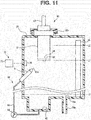
- Fig. 11 is a diagram showing a third modification of the detecting section 70 of the present embodiment.
- the detecting section 70 of the third modification includes a humidity sensor 76 that measures humidity of the air in the medicinal-solution storing section 20.
- the humidity sensor 76 is electrically connected to the measuring section 72.
- a measurement result of the humidity of the air in the medicinal-solution storing section 20 is inputted to the control section 5.
- the measurement of the humidity by the detecting section 70 is performed when the measurement surface 82 is exposed in the air.
- the control section 5 of the third modification determines that the measurement surface 82 is in the wet state.
- the control section 5 determines that the measurement surface 82 is in the dried state.
- a third embodiment of the present invention is explained. In the following explanation, only differences from the first and second embodiments are explained. Components same as the components in the first and second embodiments are denoted by the same reference numerals and signs and explanation of the components is omitted as appropriate.
- the present embodiment is different from the first and second embodiments in a configuration of the liquid supply section 60. As shown in Fig. 12 , the liquid supply section 60 of the present embodiment communicates with the dilution conduit 48 for introducing water into the medicinal-solution storing section 20.
- the liquid supply section 60 of the present embodiment supplies water supplied from the water supply source 49 to the measurement surface 82 of the concentration meter 80.
- the water supply source 49 is water equipment that supplies water at predetermined pressure. Therefore, the liquid supply section 60 of the present embodiment can discharge the water, which is liquid, from the opening 61a of the nozzle 61 without using a pump. That is, since driving of the liquid supply section 60 of the present embodiment is only switching operation of the water introducing valve 45 and the dilution valve 47, it is possible to execute the driving with a small power consumption amount.
- the endoscope reprocessor 1 of the present embodiment when the liquid surface of the medicinal solution in the medicinal-solution storing section 20 is lower than the first water level L1 and the measurement surface 82 of the concentration meter 80 is exposed in the air, since the endoscope reprocessor 1 drives the liquid supply section 60 to wet the measurement surface 82, the measurement surface 82 is kept in the wet state in which concentration measurement can be executed.
- the endoscope reprocessor 1 of the present embodiment can execute the concentration measurement of the medicinal solution by the concentration meter 80 without delay after preparing the medicinal solution and start the following reprocessing.
- the endoscope reprocessor 1 of the present embodiment may include the detecting section 70 that detects whether the measurement surface 82 is in the wet state.
- the endoscope reprocessor 1 of the present embodiment includes the detecting section 70, the endoscope reprocessor 1 has effects same as the effects of the second embodiment.
- a fourth embodiment of the present invention is explained. In the following explanation, only differences from the first embodiment are explained. Components same as the components in the first embodiment are denoted by the same reference numerals and signs and explanation of the components is omitted as appropriate.
- the medicinal-solution storing section 20 is provided as a member different from the medicinal-solution collecting section 29.
- the medicinal-solution collecting section 29 stores a medicinal solution more than an amount at least necessary for execution of reprocessing by the endoscope reprocessor 1.
- the medicinal-solution collecting section 29 communicates with the bottle connecting section 19, the collection conduit 23, the medicinal solution conduit 26, the dilution conduit 48, and the drain conduit 28a.
- the drain conduit 28a communicates with the liquid discharge port 20a provided on the bottom surface of the medicinal-solution collecting section 29 or near the bottom surface.
- the water level sensor 55 and the liquid holding section 62 are provided.
- the water level sensor 55 at least detects whether a liquid surface in the medicinal-solution collecting section 29 has reached the second water level L2 explained above and whether a liquid surface of the medicinal solution has reached the third water level L3 explained below.
- the second water level L2 is height of the liquid surface of the medicinal solution in the case in which a volume of the medicinal solution at least necessary for the execution of the reprocessing is stored in the medicinal-solution collecting section 29.
- the third water level L3 is height near the bottom surface of the medicinal-solution collecting section 29.
- the liquid holding section 62 is a concave section provided on the bottom surface of the medicinal-solution collecting section 29 and opening upward.
- the liquid holding section 62 opens in a position different from a liquid discharge port 29a. Therefore, even after the liquid in the medicinal-solution collecting section 29 is discharged from the liquid discharge port 29a, the liquid is stored in the liquid holding section 62.
- the endoscope reprocessor 1 includes a component such as a cock for discharging the liquid stored in the liquid holding section 62 to the outside of the apparatus.
- the medicinal-solution storing section 20 of the present embodiment communicates with the medicinal-solution collecting section 29 via the supply conduit 63 and a return conduit 28c.
- the supply conduit 63 causes the liquid holding section 62 of the medicinal-solution collecting section 29 and the nozzle 61 including the opening 61a disposed in the medicinal-solution storing section 20 to communicate.
- the discharge pump 64 is provided in the supply conduit 63.
- the discharge pump 64 of the discharge pump 64 is operated, whereby the liquid stored in the liquid holding section 62 is discharged from the opening 61a of the nozzle 61 and introduced into the medicinal-solution storing section 20.
- the liquid introduced into the medicinal-solution storing section 20 returns to the medicinal-solution collecting section 29 through the return conduit 28c.
- the measurement surface 82 of the concentration meter 80 is disposed at the predetermined first water level L1 in the medicinal-solution storing section 20.
- the medicinal-solution storing section 20 can store the medicinal solution to above the first water level L1.
- the liquid discharge section 28 of the present embodiment discharges the liquid such as the medicinal solution or the water from the medicinal-solution storing section 20 and the medicinal-solution collecting section 29.
- a configuration for discharging the liquid from the medicinal-solution collecting section 29 is the same as the configuration in the first to third embodiments. That is, the liquid discharge section 28 includes the drain conduit 28a, the drain valve 28b, the medicinal solution conduit 26, and the medicinal solution pump 27.
- the endoscope reprocessor 1 of the present embodiment starts operation of the medicinal solution pump 27 and stops the medicinal solution pump 27 at a point in time when it is detected by the water level sensor 55 that the height of the liquid surface in the medicinal-solution collecting section 29 is less than the third water level L3.
- the liquid is discharged from the medicinal solution nozzle 12.
- the user can discharge the liquid remaining in the medicinal-solution collecting section 29 through the drain conduit 28a at a point in time of the stop of the medicinal solution pump 27 by switching the drain valve 28b to the open state.
- the medicinal-solution storing section 20 communicates with the medicinal-solution collecting section 29 via the return conduit 28c. Therefore, if the liquid in the medicinal-solution collecting section 29 is discharged by the liquid discharge section 28, the liquid in the medicinal-solution storing section 20 is also discharged through the return conduit 28c and the medicinal-solution collecting section 29. That is, the liquid discharge section 28 of the present embodiment includes the return conduit 28c.
- the liquid supply section 60 of the present embodiment is a component same as the liquid supply section 60 of the first embodiment. That is, after the liquid is discharged from the medicinal-solution storing section 20 and the medicinal-solution collecting section 29 by the liquid discharge section 28, the liquid supply section 60 supplies the liquid stored in the liquid holding section 62 to the measurement surface 82 of the permeation membrane 86 of the concentration meter 80.
- the opening 61a of the nozzle 61 of the liquid supply section 60 opens toward the measurement surface 82. At least a part of the liquid discharged from the opening 61 a of the nozzle 61 is blown against the measurement surface 82 and wets the measurement surface 82.
- the nozzle 61 may be disposed at a position for causing the discharged liquid to flow along, for example, the outer surface of the housing 81 or the inner wall surface of the medicinal-solution storing section 20 and thereafter reach the measurement surface 82.
- the discharge pump 64 is operated to transfer the medicinal solution in the medicinal-solution collecting section 29 into the medicinal-solution storing section 20.
- Operation of the endoscope reprocessor 1 of the present embodiment is the same as the operation explained with reference to Fig. 3 to Fig. 5 in the first embodiment. That is, the operation of the endoscope reprocessor 1 of the present embodiment is the same as the operation in the first embodiment.
- the endoscope reprocessor 1 of the present embodiment when the liquid is discharged from the medicinal-solution collecting section 29 and the medicinal-solution storing section 20 and the measurement surface 82 of the concentration meter 80 is exposed in the air, since the endoscope reprocessor 1 drives the liquid supply section 60 to wet the measurement surface 82, the measurement surface 82 is kept in the wet state in which the concentration measurement can be executed.
- the endoscope reprocessor 1 of the present embodiment can execute the concentration measurement of the medicinal solution by the concentration meter 80 without delay after preparing the medicinal solution and start the following reprocessing.
- the endoscope reprocessor 1 drives the liquid supply section 60 to wet the measurement surface 82.
- the control section 5 intermittently drives the liquid supply section 60 in a period in which the measurement surface 82 of the concentration meter 80 is exposed in the air. Therefore, it is possible to reduce a consumed amount of electric power necessary for driving the liquid supply section 60.
- the endoscope reprocessor 1 of the modification includes a water level sensor 56 in the medicinal-solution storing section 20.
- the water level sensor 56 detects whether the height of the liquid surface of the medicinal-solution storing section 20 has reached the first water level L1.
- the water level sensor 56 is electrically connected to the control section 5.
- a detection result by the water level sensor 56 is inputted to the control section 5.
- the water level sensor 56 may be a so-called electrode-type water level sensor including, for example, a plurality of electrodes disposed spaced apart from one another, the electrode-type water level sensor detecting, based on presence or absence of electric conduction among the plurality of electrodes that changes according to whether the plurality of electrodes are sunk in liquid, whether the liquid surface has reached a predetermined water level.
- the water level sensor 56 may be a so-called float-type water level sensor that detects, based on an operation state of a switch that opens and closes according to up and down movements of a float floating on the medicinal solution, whether the liquid surface has reached the predetermined water level.
- the endoscope reprocessor 1 of the modification when performing the concentration measurement of the medicinal solution by the concentration meter 80, prior to execution of the concentration measurement, the endoscope reprocessor 1 operates the discharge pump 64 and transfers the medicinal solution in the medicinal-solution collecting section 29 into the medicinal-solution storing section 20.
- the endoscope reprocessor 1 executes the concentration measurement of the medicinal solution by the concentration meter 80.
- the modification is different from the embodiments described above in the liquid supply operation in step S430.
- the endoscope reprocessor 1 continues the operation of the discharge pump 64 until it is detected that the height of the liquid surface in the medicinal-solution storing section 20 is equal to or greater than the first water level L1. That is, in the liquid supply operation of the modification, the endoscope reprocessor 1 immerses the measurement surface 82 of the permeation membrane 86 of the concentration meter 80 in the liquid.
- a fifth embodiment of the present invention is explained. In the following explanation, only differences from the fourth embodiment are explained. Components same as the components in the fourth embodiment are denoted by the same reference numerals and signs and explanation of the components is omitted as appropriate.
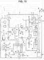
- the endoscope reprocessor 1 of the present embodiment shown in Fig. 15 includes the detecting section 70 that detects whether the measurement surface 82 of the permeation membrane 86 of the concentration meter 80 is in the wet state.
- a configuration of the detecting section 70 is not particularly limited as explained in the second embodiment.
- the detecting section 70 may be configured to measure an electric resistance value of the measurement surface 82, may be configured to measure reflectance of light of the measurement surface 82, may be configured to measure a temperature difference between the measurement surface 82 and ambient temperature, or may be configured to measure humidity in the medicinal-solution storing section 20.
- the endoscope reprocessor 1 of the present embodiment is different from the fourth embodiment in a moisture retaining operation.
- the moisture retaining operation of the present embodiment is the same as the moisture retaining operation of the second embodiment explained with reference to Fig. 8 .
- the endoscope reprocessor 1 drives the liquid supply section 60 to wet the measurement surface 82.
- the present embodiment as in the second embodiment, it is possible to keep the measurement surface 82 of the concentration meter 80 in the wet state in which concentration measurement can be executed.
- the endoscope reprocessor 1 of the present embodiment can execute the concentration measurement of the medicinal solution by the concentration meter 80 without delay after preparing the medicinal solution and start the following reprocessing.
- the endoscope reprocessor 1 drives the liquid supply section 60 only when the measurement surface 82 is exposed in the air and the detecting section 70 detects that the measurement surface 82 is in the dried state. Therefore, it is possible to reduce a consumed amount of electric power necessary for driving the liquid supply section 60. In the present embodiment, it is possible to surely keep the measurement surface 82 in the wet state without being affected by changes in temperature, humidity, and the like of an ambient atmosphere in which the endoscope reprocessor 1 is placed.
- a sixth embodiment of the present invention is explained. In the following explanation, only differences from the fourth and fifth embodiments are explained. Components same as the components in the fourth and fifth embodiments are denoted by the same reference numerals and signs and explanation of the components is omitted as appropriate.
- the endoscope reprocessor 1 of the present embodiment shown in Fig. 16 is different from the fourth and fifth embodiments in a configuration of the liquid supply section 60.
- the nozzle 61 of the liquid supply section 60 of the present embodiment communicates with the dilution conduit 48 for introducing water into the medicinal-solution collecting section 29.
- the water supplied from the dilution conduit 48 is introduced into the medicinal-solution collecting section 29 through the nozzle 61, the medicinal-solution storing section 20, and the return conduit 28c. That is, the medicinal-solution storing section 20 of the present embodiment is provided on a route for introducing the water supplied from the water supply source 49 into the medicinal-solution collecting section 29.
- the liquid supply section 60 of the present embodiment supplies the water supplied from the water supply source 49 to the measurement surface 82 of the concentration meter 80.
- the water supply source 49 is waterworks that supplies water at predetermined pressure. Therefore, the liquid supply section 60 of the present embodiment can discharge the water, which is liquid, from the opening 61a of the nozzle 61 without using a pump. That is, since driving of the liquid supply section 60 of the present embodiment is only switching operation of the water introducing valve 45 and the dilution valve 47, it is possible to execute the driving with a small power consumption amount.
- the endoscope reprocessor 1 of the present embodiment when the measurement surface 82 of the concentration meter 80 is exposed in the air, since the endoscope reprocessor 1 drives the liquid supply section 60 to wet the measurement surface 82, the measurement surface 82 is kept in the wet state in which concentration measurement can be executed.
- the endoscope reprocessor 1 of the present embodiment can execute the concentration measurement of the medicinal solution by the concentration meter 80 without delay after preparing the medicinal solution and start the following reprocessing.
- the endoscope reprocessor 1 of the present embodiment may include the detecting section 70 that detects whether the measurement surface 82 is in the wet state.
- the endoscope reprocessor 1 of the present embodiment includes the detecting section 70, the endoscope reprocessor 1 has effects same as the effects of the fifth embodiment.
- a seventh embodiment of the present invention is explained. In the following explanation, only differences from the fourth embodiment are explained. Components same as the components in the fourth embodiment are denoted by the same reference numerals and signs and explanation of the components is omitted as appropriate.
- the medicinal-solution storing section 20 is provided halfway in the endoscope circulation conduit 30.
- the endoscope circulation conduit 30 is a conduit branching from the circulation conduit 13a and connected to the channel valve 32.
- the endoscope circulation conduit 30 of the present embodiment is configured by concatenating a first conduit 30a, a liquid holding section 65, the supply conduit 63, the nozzle 61, the medicinal-solution storing section 20, and a second conduit 28d in order from a branching section of the circulation conduit 13a.
- the circulation pump 33 is provided in the supply conduit 63. If the circulation pump 33 operates in a state in which liquid is stored in the treatment tank 2, the liquid in the treatment tank 2 is introduced into the channel valve 32 through the circulation conduit 13a, the first conduit 30a, the liquid holding section 65, the supply conduit 63, the nozzle 61, the medicinal-solution storing section 20, and the second conduit 28d.
- the liquid holding section 65 stores a volume of liquid with which moisture retaining treatment can be continued for a predetermined time period.
- the predetermined time period in which the moisture retaining treatment should be continued is, for example, 72 hours longer than a time period from a Friday evening to a Monday morning.
- the liquid holding section 65 may function as the first conduit 30a as well.
- the measurement surface 82 of the concentration meter 80 is disposed at the predetermined first water level L1 in the medicinal-solution storing section 20.
- the medicinal-solution storing section 20 can store the medicinal solution to above the first water level L1.
- the liquid discharge section 28 of the present embodiment discharges the liquid such as the medicinal solution or the water from the medicinal-solution storing section 20.
- the liquid in the medicinal-solution storing section 20 is discharged from the second conduit 28d.
- the water level sensor 56 is provided in the medicinal-solution storing section 20.
- the water level sensor 56 detects whether the height of the liquid surface in the medicinal-solution storing section 20 has reached the first water level L1.
- the water level sensor 56 is electrically connected to the control section 5. A detection result by the water level sensor 56 is inputted to the control section 5.
- the water level sensor 56 may be a so-called electrode-type water level sensor including, for example, a plurality of electrodes disposed spaced apart from one another, the electrode-type water level sensor detecting, based on presence or absence of electric conduction among the plurality of electrodes that changes according to whether the plurality of electrodes are sunk in liquid, whether the liquid surface has reached a predetermined water level.
- the water level sensor 56 may be a so-called float-type water level sensor that detects, based on an operation state of a switch that opens and closes according to up and down movements of a float floating on the medicinal solution, whether the liquid surface has reached the predetermined water level.
- the liquid supply section 60 of the present embodiment supplies the liquid stored in the liquid holding section 65 to the measurement surface 82 of the permeation membrane 86 of the concentration meter 80.
- the liquid such as the water or the medicinal solution flows in the circulation conduit 30. Therefore, after the execution of the reprocessing, the liquid is stored in the liquid holding section 65.
- the opening 61a of the nozzle 61 of the liquid supply section 60 opens toward the measurement surface 82. At least a part of the liquid discharged from the opening 61a of the nozzle 61 is blown against the measurement surface 82 and wets the measurement surface 82.
- the nozzle 61 may be disposed at a position for causing the discharged liquid to flow along, for example, the outer surface of the housing 81 or the inner wall surface of the medicinal-solution storing section 20 and thereafter reach the measurement surface 82.
- the medicinal solution pump 27 when concentration measurement of the medicinal solution by the concentration meter 80 is performed, prior to execution of the concentration measurement, the medicinal solution pump 27 is operated to introduce the medicinal solution in the medicinal-solution collecting section 29 into the treatment tank 2. Thereafter, the circulation pump 33 is operated to introduce the medicinal solution in the treatment tank 2 into the medicinal-solution storing section 20 through the circulation port 13, the circulation conduit 13a, the first conduit 30a, the supply conduit 63, and the nozzle 61 and executes the concentration measurement.
- FIG. 18 A flow of a main routine shown in Fig. 18 is started, for example, when the power supply of the endoscope reprocessor 1 is brought into an ON state. Note that an input of an operation instruction from the user to the endoscope reprocessor 1 is performed via the operation section 7.
- step S40 operation performed after it is determined in step S40 that the instruction for executing the reprocessing is not inputted (NO in step S40) is different from the operation explained in the first embodiment.
- step S40 When determining in step S40 that the instruction for executing the reprocessing is not inputted, the endoscope reprocessor 1 shifts to step S201.
- step S201 the endoscope reprocessor 1 checks, with the water level sensor 56, whether the height of the liquid surface in the medicinal-solution storing section 20 is equal to or greater than the first water level L1.
- the endoscope reprocessor 1 shifts to step S220 and executes moisture retaining operation shown in the flowchart of Fig. 19 .
- a state in which the height of the liquid surface in the medicinal-solution storing section 20 has not reached the first water level L1 is a state in which the liquid in the medicinal-solution storing section 20 is discharged and the measurement surface 82 of the concentration meter 80 is exposed in the air.
- the moisture retaining operation in step S220 is explained below. After executing step S220, the endoscope reprocessor 1 returns to step S10.
- step S201 When determining in step S201 that the height of the liquid surface in the medicinal-solution storing section 20 is equal to or greater than the first water level L1 (YES in step S211), the endoscope reprocessor 1 returns to step S10.
- step S310 the endoscope reprocessor 1 determines whether an instruction for power-on is inputted by the user.
- the endoscope reprocessor 1 shifts to step S350, starts the main routine shown in Fig. 18 , and ends the power saving mode.
- step S310 when determining in step S310 that the instruction for power-on is not inputted, the endoscope reprocessor 1 shifts to step S321.
- step S321 the endoscope reprocessor 1 checks, with the water level sensor 56, whether the height of the liquid surface in the medicinal-solution storing section 20 is equal to or greater than the first water level L1.
- step S321 the endoscope reprocessor 1 shifts to step S340 and executes moisture retaining operation shown in the flowchart of Fig. 20 .
- the moisture retaining operation in step S340 is explained below.
- step S340 the endoscope reprocessor 1 returns to step S310.
- the moisture retaining operation executed in step S220 and step S340 is explained.
- the moisture retaining operation is the same as the moisture retaining operation in the first embodiment.
- step S410 the endoscope reprocessor 1 recognizes the exposure time period T1 in which the measurement surface 82 of the concentration meter 80 is exposed in the air after coming into contact with the liquid.
- the exposure time period T1 is a value of a shorter one of an elapsed time period from a point in time when the discharge process (step S80) for discharging the medicinal solution from the medicinal-solution storing section 20 with the liquid discharge section 28 is executed last and an elapsed time period from a point in time when a liquid supply operation for supplying the liquid to the measurement surface 82 with the liquid supply section 60 is executed last.
- the exposure time period T1 is calculated from operation history information of the endoscope reprocessor 1 stored by the control section 5.
- the endoscope reprocessor 1 shifts to step S430 and drives the liquid supply section 60 to execute the liquid supply operation for supplying the liquid to the measurement surface 82.
- the endoscope reprocessor 1 continues operation of the discharge pump 64 for a predetermined time period and discharges the medicinal solution stored in the liquid holding section 62 from the nozzle 61 toward the measurement surface 82.
- the measurement surface 82 of the permeation membrane 86 included in the concentration meter 80 is in contact with the medicinal solution for a predetermined time period. Therefore, the measurement surface 82 changes to the wet state.
- the endoscope reprocessor 1 ends the moisture retaining operation.
- step S410 when determining that the exposure time period T1 recognized in step S410 is shorter than the predetermined time period Tth (NO in step S420), the endoscope reprocessor 1 skips step S430 and ends the moisture retaining operation.
- the endoscope reprocessor 1 of the present embodiment when the liquid surface of the medicinal solution in the medicinal-solution storing section 20 is lower than the first water level L1 and the measurement surface 82 of the concentration meter 80 is exposed in the air, since the endoscope reprocessor 1 drives the liquid supply section 60 to wet the measurement surface 82, the measurement surface 82 is kept in the wet state in which concentration measurement can be executed.
- the endoscope reprocessor 1 of the present embodiment can execute the concentration measurement of the medicinal solution by the concentration meter 80 without delay after preparing the medicinal solution and start the following reprocessing.
- the endoscope reprocessor 1 drives the liquid supply section 60 to wet the measurement surface 82.
- the control section 5 intermittently drives the liquid supply section 60 in a period in which the measurement surface 82 of the concentration meter 80 is exposed in the air. Therefore, it is possible to reduce a consumed amount of electric power necessary for driving the liquid supply section 60.
Landscapes
- Health & Medical Sciences (AREA)
- Life Sciences & Earth Sciences (AREA)
- General Health & Medical Sciences (AREA)
- Chemical & Material Sciences (AREA)
- Surgery (AREA)
- Physics & Mathematics (AREA)
- Molecular Biology (AREA)
- Pathology (AREA)
- Animal Behavior & Ethology (AREA)
- Public Health (AREA)
- Veterinary Medicine (AREA)
- Chemical Kinetics & Catalysis (AREA)
- Engineering & Computer Science (AREA)
- Heart & Thoracic Surgery (AREA)
- Medical Informatics (AREA)
- Biophysics (AREA)
- Nuclear Medicine, Radiotherapy & Molecular Imaging (AREA)
- Optics & Photonics (AREA)
- Radiology & Medical Imaging (AREA)
- Biomedical Technology (AREA)
- General Physics & Mathematics (AREA)
- Biochemistry (AREA)
- Immunology (AREA)
- Analytical Chemistry (AREA)
- Electrochemistry (AREA)
- General Chemical & Material Sciences (AREA)
- Epidemiology (AREA)
- Mechanical Engineering (AREA)
- Endoscopes (AREA)
- Instruments For Viewing The Inside Of Hollow Bodies (AREA)
Abstract
Description
- The present invention relates to an endoscope reprocessor that applies reprocessing, in which a medicinal solution is used, to an endoscope.
- An endoscope used in a medical field is subjected to reprocessing such as cleaning treatment and disinfecting treatment after use. An endoscope reprocessor that automatically performs the reprocessing of the endoscope is known. The endoscope reprocessor includes a medicinal solution tank that stores a medicinal solution used for the reprocessing. In order to determine whether the medicinal solution used for the reprocessing is usable, a concentration meter for measuring concentration of the medicinal solution disclosed in, for example, Japanese Patent Application Laid-Open Publication No.
2006-126046 - When a measurement surface that comes into contact with a medicinal solution during concentration measurement is in a dried state, a concentration meter needs a longer standby time period until a correct measurement result can be obtained after the measurement surface comes into contact with the medicinal solution compared with when the measurement surface is in a wet state. In order to reduce the standby time period, in the concentration meter disclosed in Japanese Patent Application Laid-Open Publication No.
2006-126046 - Depending on a structure of a concentration meter, a measurement surface sometimes is not instantaneously brought into a measurable wet state simply by pressing the measurement surface against the sponge-like porous material wet by the preservation liquid as in the concentration meter disclosed in Japanese Patent Application Laid-Open Publication No.
2006-126046 - The present invention solves the problems explained above, and an object of the present invention is to provide an endoscope reprocessor that keeps a measurement surface of a concentration meter in a sufficient wet state.
- An endoscope reprocessor according to an aspect of the present invention includes: a concentration meter including a housing, an electrode housed in the housing, a permeation membrane held by the housing, and internal liquid encapsulated in the housing, the concentration meter measuring concentration of a medicinal solution; a medicinal-solution storing section including a holding section configured to hold the concentration meter such that the permeation membrane is disposed at a predetermined water level, the medicinal-solution storing section storing the medicinal solution to a water level higher than the predetermined water level; a liquid discharge section configured to discharge the medicinal solution from the medicinal-solution storing section; a liquid supply section configured to supply liquid to the permeation membrane of the concentration meter; and a control section connected to the liquid discharge section and the liquid supply section, the control section driving the liquid supply section to wet the permeation membrane when the medicinal solution in the medicinal-solution storing section is lower than the predetermined water level.
-
-
Fig. 1 is a diagram showing a schematic configuration of an endoscope reprocessor of a first embodiment; -
Fig 2 is a partial sectional view of a medicinal-solution storing section and a concentration meter of the first embodiment; -
Fig. 3 is a flowchart showing a main routine of the endoscope reprocessor of the first embodiment; -
Fig. 4 is a flowchart of a power saving mode of the endoscope reprocessor of the first embodiment; -
Fig. 5 is a flowchart of moisture retaining operation of the endoscope reprocessor of the first embodiment; -
Fig. 6 is a diagram showing a modification of a liquid supply section of the first embodiment; -
Fig. 7 is a diagram showing a configuration of a detecting section disposed in a medicinal-solution storing section of a second embodiment; -
Fig. 8 is a flowchart of moisture retaining operation of an endoscope reprocessor of the second embodiment; -
Fig. 9 is a diagram showing a first modification of a detecting section of the second embodiment; -
Fig. 10 is a diagram showing a second modification of the detecting section of the second embodiment; -
Fig. 11 is a diagram showing a third modification of the detecting section of the second embodiment; -
Fig. 12 is a diagram showing a schematic configuration of an endoscope reprocessor of a third embodiment; -
Fig. 13 is a diagram showing a schematic configuration of an endoscope reprocessor of a fourth embodiment; -
Fig. 14 is a diagram showing a modification of the endoscope reprocessor of the fourth embodiment; -
Fig. 15 is a diagram showing a schematic configuration of an endoscope reprocessor of a fifth embodiment; -
Fig. 16 is a diagram showing a schematic configuration of an endoscope reprocessor of a sixth embodiment; -
Fig. 17 is a diagram showing a schematic configuration of an endoscope reprocessor of a seventh embodiment; -
Fig. 18 is a flowchart showing a main routine of the endoscope reprocessor of the seventh embodiment; -
Fig. 19 is a flowchart of a power saving mode of the endoscope reprocessor of the seventh embodiment; and -
Fig. 20 is a flowchart of a moisture retaining operation of the endoscope reprocessor of the seventh embodiment. - Preferred modes of the present invention are explained below with reference to the drawings. Note that, in the respective figures used for the following explanation, in order to show respective components in recognizable sizes on the drawings, scales are varied for each of the components. The present invention is not limited to only numbers of the components, shapes of the components, ratios of sizes of the components, and relative positional relations among the respective components described in the figures.
- An example of an embodiment of the present invention is explained below. An
endoscope reprocessor 1 shown inFig. 1 is an apparatus that applies reprocessing to an endoscope. The reprocessing referred to herein is not particularly limited and may be any one of rinsing treatment by water, cleaning treatment for removing strains of organic matters and the like, disinfecting treatment for disabling predetermined microorganisms, sterilizing treatment for eliminating or killing all microorganisms, and a combination of the foregoing. - Note that, in the following explanation, upward indicates a position further away from a ground with respect to a comparison target and downward indicates a position closer to the ground with respect to the comparison target. High and low in the following explanation indicate a height relation along a gravity direction.
- The
endoscope reprocessor 1 includes acontrol section 5, apower supply section 6, atreatment tank 2, a medicinal-solution storingsection 20, aconcentration meter 80, aliquid discharge section 28, and aliquid supply section 60. - The
control section 5 can include an arithmetic unit (a CPU), a storage device (a RAM), an auxiliary storage device, an input/output device, a power control device and the like. Thecontrol section 5 includes a configuration for controlling, based on a predetermined program, operations of respective parts configuring theendoscope reprocessor 1. Operations of the respective components included in theendoscope reprocessor 1 in the following explanation are controlled by thecontrol section 5 even when not particularly described. - The
power supply section 6 supplies electric power to the respective parts of theendoscope reprocessor 1. Thepower supply section 6 distributes electric power obtained from an outside such as a commercial power supply to the respective parts. Note that thepower supply section 6 may include a power generating device or a battery. - The
treatment tank 2 is formed in a concave shape including an opening section and is capable of storing liquid inside. A not-shown endoscope can be disposed in thetreatment tank 2. In the present embodiment, as an example, alid 3 for opening and closing the opening section of thetreatment tank 2 is provided in an upper part of thetreatment tank 2. When reprocessing is applied to the endoscope in thetreatment tank 2, the opening section of thetreatment tank 2 is closed by thelid 3. - In the
treatment tank 2, amedicinal solution nozzle 12, aliquid discharge port 11, acirculation port 13, acirculation nozzle 14, a cleaningliquid nozzle 15, anendoscope connecting section 16, and anaccessory case 17 are provided. - The
medicinal solution nozzle 12 is an opening section that communicates with the medicinal-solution storingsection 20 via a medicinal solution conduit 26. The medicinal-solution storingsection 20 stores a medicinal solution. A type of the medicinal solution stored by the medicinal-solution storingsection 20 is not particularly limited. However, in the present embodiment, as an example, the medicinal solution is disinfectant liquid such as acetic peracid used for the disinfecting treatment. However, the present invention is not limited to this. As the medicinal solution, cleaning liquid used for the cleaning treatment, a high-volatile solution used for drying, and the like can be selected as appropriate according to purposes. - In the present embodiment, as an example, the medicinal solution is obtained by diluting, with water, at a predetermined ratio, a stock solution of the medicinal solution supplied from a
medicinal solution bottle 18. The medicinal-solution storingsection 20 of the present embodiment communicates with abottle connecting section 19 that introduces the stock solution of the medicinal solution supplied from themedicinal solution bottle 18 into the medicinal-solution storing section 20 and adilution conduit 48 for introducing water for dilution into the medicinal-solution storing section 20. Themedicinal solution bottle 18 is connected to thebottle connecting section 19, whereby the stock solution of the medicinal solution is introduced into the medicinal-solution storing section 20. A configuration for introducing the water from thedilution conduit 48 into the medicinal-solution storing section 20 is explained below. - Note that the
endoscope reprocessor 1 does not have to include the configuration for diluting the medicinal solution with the water or the like. When a plurality of kinds of stock solutions are mixed and used as the medicinal solution, thebottle connecting section 19 is connectable to a plurality ofmedicinal solution bottles 18. - In the present embodiment, as an example, the medicinal solution is usable when concentration is within a predetermined range in which the medicinal solution has medicinal effects. When the
endoscope reprocessor 1 is not executing operation in which the medicinal solution is used, the medicinal-solution storing section 20 stores the entire medicinal solution in theendoscope reprocessor 1. That is, in the present embodiment, the medicinal-solution storing section 20 also functions as a medicinal-solution collecting section 29 that collects and stores the medicinal solution in theendoscope reprocessor 1. In the following explanation, when the medicinal-solution storing section 20 and the medicinal-solution collecting section 29 are not distinguished, the medicinal-solution storing section 20 and the medicinal-solution collecting section 29 are simply referred to as medicinal-solution storing section 20. - Note that the medicinal-
solution storing section 20 may be provided separately from the medicinal-solution collecting section 29. When the medicinal-solution storing section 20 is a component different from the medicinal-solution collecting section 29, the capacity of the medicinal-solution storing section 20 may be smaller than the capacity of the medicinal-solution collecting section 29. - In the medicinal-
solution storing section 20, theconcentration meter 80, theliquid discharge section 28, and theliquid supply section 60 are also disposed. Detailed configurations of these components and the medicinal-solution storing section 20 are explained below. - A
medicinal solution pump 27 is provided in themedicinal solution conduit 26. By operating themedicinal solution pump 27, the medicinal solution in the medicinal-solution storing section 20 is transferred into thetreatment tank 2 through themedicinal solution conduit 26 and themedicinal solution nozzle 12. - The
liquid discharge port 11 is an opening section provided in a lowest part in thetreatment tank 2. Theliquid discharge port 11 is connected to adischarge conduit 21. Thedischarge conduit 21 causes theliquid discharge port 11 and a switchingvalve 22 to communicate. Acollection conduit 23 and a discardingconduit 25 are connected to the switchingvalve 22. The switchingvalve 22 can be switched to a state in which thedischarge conduit 21 is closed, a state in which thedischarge conduit 21 and thecollection conduit 23 are caused to communicate, or a state in which thedischarge conduit 21 and the discardingconduit 25 are caused to communicate. - The
collection conduit 23 causes the medicinal-solution storing section 20 and the switchingvalve 22 to communicate. Adischarge pump 24 is provided in the discardingconduit 25. The discardingconduit 25 is connected to a liquid discharge facility for receiving the liquid discharged from theendoscope reprocessor 1. - If the switching
valve 22 is switched to a closed state, it is possible to store the liquid in thetreatment tank 2. When the medicinal solution is stored in thetreatment tank 2, if the switchingvalve 22 is switched to the state in which thedischarge conduit 21 and thecollection conduit 23 communicate, the medicinal solution is transferred from thetreatment tank 2 to the medicinal-solution storing section 20. If the switchingvalve 22 is switched to the state in which thedischarge conduit 21 and the discardingconduit 25 communicate and the operation of thedischarge pump 24 is started, the liquid in thetreatment tank 2 is delivered to the liquid discharge facility through the discardingconduit 25. - The
circulation port 13 is an opening section provided near a bottom surface of thetreatment tank 2. Thecirculation port 13 communicates with acirculation conduit 13a. Thecirculation conduit 13a branches to two conduits of anendoscope circulation conduit 30 and a treatmenttank circulation conduit 40. - The
endoscope circulation conduit 30 causes thecirculation conduit 13a and achannel valve 32 explained below to communicate. Acirculation pump 33 is provided in theendoscope circulation conduit 30. Thecirculation pump 33 operates to transfer fluid in theendoscope circulation conduit 30 toward thechannel valve 32. - Besides the
endoscope circulation conduit 30, anair intake conduit 34, analcohol conduit 38, and adelivery conduit 31 are connected to thechannel valve 32. Thechannel valve 32 selectively causes any one of theendoscope circulation conduit 30, theair intake conduit 34, and thealcohol conduit 38 to communicate with thedelivery conduit 31. - One end portion of the
air intake conduit 34 is opened to an atmosphere. The other end portion is connected to thechannel valve 32. Note that, although not shown in the figure, a filter for filtering passing gas is provided at the one end portion of theair intake conduit 34. Anair pump 35 is provided in theair intake conduit 34. Theair pump 35 operates to thereby transfer the gas in theair intake conduit 34 toward thechannel valve 32. - The
alcohol conduit 38 causes analcohol tank 37 that stores alcohol and thechannel valve 32 to communicate. Examples of the alcohol stored in thealcohol tank 37 include ethanol. Alcohol concentration can be selected as appropriate. Analcohol pump 39 is provided in thealcohol conduit 38. Thealcohol pump 39 operates to thereby transfer the alcohol in thealcohol tank 37 toward thechannel valve 32. - When liquid is stored in the
treatment tank 2, if thechannel valve 32 is switched to a state in which thedelivery conduit 31 and theendoscope circulation conduit 30 communicate and operation of thecirculation pump 33 is started, the liquid in thetreatment tank 2 is sent into thedelivery conduit 31 through thecirculation port 13, thecirculation conduit 13a, and theendoscope circulation conduit 30. - If the
channel valve 32 is switched to a state in which thedelivery conduit 31 and theair intake conduit 34 communicate and operation of theair pump 35 is started, the air is sent into thedelivery conduit 31. If thechannel valve 32 is switched to a state in which thedelivery conduit 31 and thealcohol conduit 38 communicate and operation of thealcohol pump 39 is started, the alcohol in thealcohol tank 37 is sent into thedelivery conduit 31. - The
delivery conduit 31 branches to anendoscope connection conduit 31b and acase connection conduit 31c. Theendoscope connection conduit 31b is connected to theendoscope connecting section 16. Thecase connection conduit 31c is connected to theaccessory case 17. - A
channel switching section 31 a is provided in thedelivery conduit 31. Thechannel switching section 31a is capable of switching to which of theendoscope connection conduit 31b and thecase connection conduit 31c the fluid sent into thedelivery conduit 31 from thechannel valve 32 is fed. Note that pressure on theendoscope connection conduit 31b side may be controlled to be constant during the switching. - The
endoscope connecting section 16 is connected to a pipe sleeve provided in the endoscope via a not-shown endoscope tube. Theaccessory case 17 is a basket-like member that houses not-shown accessories of the endoscope. Therefore, the fluid sent into thedelivery conduit 31 from thechannel valve 32 is introduced into the pipe sleeve of the endoscope or into theaccessory case 17. - The treatment
tank circulation conduit 40 causes thecirculation conduit 13a and thecirculation nozzle 14 to communicate. Thecirculation nozzle 14 is an opening section provided in thetreatment tank 2. Acirculation pump 41 is provided in the treatmenttank circulation conduit 40. - A three-
way valve 42 is provided between thecirculation pump 41 of the treatmenttank circulation conduit 40 and thecirculation nozzle 14. Awater supply conduit 43 is connected to the three-way valve 42. The three-way valve 42 can be switched to a state in which thecirculation nozzle 14 and the treatmenttank circulation conduit 40 are caused to communicate or a state in which thecirculation nozzle 14 and thewater supply conduit 43 are caused to communicate. - The
water supply conduit 43 causes the three-way valve 42 and a water-supply-source connecting section 46 to communicate. In thewater supply conduit 43, awater introducing valve 45 for opening and closing thewater supply conduit 43 and awater filter 44 for filtering water are provided. The water-supply-source connecting section 46 is connected to, via a hose or the like, awater supply source 49 such as waterworks that delivers water. - A
dilution valve 47 is provided in a section between thewater filter 44 and the three-way valve 42 of thewater supply conduit 43. Thedilution conduit 48 that causes thedilution valve 47 and the medicinal-solution storing section 20 to communicate is connected to thedilution valve 47. Thedilution valve 47 can be switched to a state in which thewater filter 44 and the three-way valve 42 are caused to communicate or a state in which thewater filter 44 and thedilution conduit 48 are caused to communicate. - When liquid is stored in the
treatment tank 2, if the three-way valve 42 is switched to the state in which thecirculation nozzle 14 and the treatmenttank circulation conduit 40 are caused to communicate, thedilution valve 47 is switched to the state in which thewater filter 44 and the three-way valve 42 are caused to communicate, and operation of thecirculation pump 41 is started, the liquid in thetreatment tank 2 is discharged from thecirculation nozzle 14 through thecirculation port 13, thecirculation conduit 13a, and the treatmenttank circulation conduit 40. - If the three-
way valve 42 is switched to the state in which thecirculation nozzle 14 and thewater supply conduit 43 are caused to communicate, thedilution valve 47 is switched to the state in which thewater filter 44 and the three-way valve 42 are caused to communicate, and thewater introducing valve 45 is switched to the open state, the water supplied from thewater supply source 49 is discharged from thecirculation nozzle 14. The liquid discharged from thecirculation nozzle 14 is introduced into thetreatment tank 2. - If the
dilution valve 47 is switched to the state in which thewater filter 44 and thedilution conduit 48 are caused to communicate and thewater introducing valve 45 is switched to the open state, the water supplied from thewater supply source 49 is introduced into the medicinal-solution storing section 20. - The cleaning
liquid nozzle 15 is an opening section that communicates with, via a cleaningliquid conduit 51, a cleaningliquid tank 50 that stores the cleaning liquid. The cleaning liquid is used for the cleaning treatment. A cleaningliquid pump 52 is provided in the cleaningliquid conduit 51. When the cleaningliquid pump 52 is operated, the cleaning liquid in the cleaningliquid tank 50 is transferred into thetreatment tank 2. - The
endoscope reprocessor 1 includes anoperation section 7 and anoutput section 8 configuring a user interface that performs exchange of information with a user. Theoperation section 7 and theoutput section 8 are electrically connected to thecontrol section 5. - The
operation section 7 includes an operation member such as a push switch or a touch sensor. Theoutput section 8 includes, for example, a display device that displays images and characters, a light emitting device that emits light, a speaker that emits sound, or a combination of the foregoing. Note that theoperation section 7 and theoutput section 8 may be included in an electronic device that performs wireless communication with thecontrol section 5. - A configuration of the medicinal-
solution storing section 20 is explained. In the medicinal-solution storing section 20, theconcentration meter 80, awater level sensor 55, theliquid discharge section 28, and theliquid supply section 60 are disposed. - The
concentration meter 80 measures concentration of a specific substance, which is a measurement target, in the medicinal solution in contact with ameasurement surface 82. A partial sectional view of the medicinal-solution storing section 20 and theconcentration meter 80 is shown inFig. 2 . - The
concentration meter 80 may be included in theendoscope reprocessor 1 and electrically connected to thecontrol section 5 or may operate alone without being included in theendoscope reprocessor 1. In the present embodiment, as an example, theconcentration meter 80 is electrically connected to thecontrol section 5. Information concerning a measurement result of concentration of the medicinal solution measured by theconcentration meter 80 is inputted to thecontrol section 5. - The
measurement surface 82 is provided in a part of an outer surface of ahousing 81. Thehousing 81 is a container-like member in which anopening section 81 a is provided. Theopening section 81 a is sealed by apermeation membrane 86.Internal liquid 83 is encapsulated in an inside of theopening section 81a of thehousing 81. - The
measurement surface 82 is a surface on an opposite side of a region of thepermeation membrane 86 in contact with theinternal liquid 83. Thepermeation membrane 86 allows a substance, which is a measurement target, in the medicinal solution in contact with themeasurement surface 82 to permeate into theinternal liquid 83 side. That is, substance concentration in the internal liquid 83 changes according to substance concentration of the medicinal solution in contact with themeasurement surface 82. - In the
housing 81, a plurality ofelectrodes 84 are disposed spaced apart from one another in theinternal liquid 83. The plurality ofelectrodes 84 are connected to a not-shown control device of theconcentration meter 80 via anelectric cable 87. Note that the control device of thehousing 81 may be configured integrally with thehousing 81. As explained above, in the present embodiment, the control device of theconcentration meter 80 is included in thecontrol section 5. - The
concentration meter 80 measures a change in a potential difference that occurs among the plurality ofelectrodes 84 immersed in theinternal liquid 83 or a change in a value of an electric current flowing between a pair ofelectrodes 84 and measures, based on a value of the measurement, concentration of the medicinal solution in contact with themeasurement surface 82. Since a principle and a configuration of the concentration measurement in theconcentration meter 80 are well known, detailed explanation of the principle and the configuration is omitted. - In the medicinal-
solution storing section 20, a holdingsection 20b that holds thehousing 81 of theconcentration meter 80 is provided. Themeasurement surface 82 of theconcentration meter 80 held by the holdingsection 20b is disposed at a predetermined first water level L1 in the medicinal-solution storing section 20. In the present embodiment, themeasurement surface 82 of theconcentration meter 80 held by the holdingsection 20b faces downward. The predetermined water level L1 is height of a liquid surface of the medicinal solution in the medicinal-solution storing section 20 in the case in which a predetermined volume of the medicinal solution is stored in the medicinal-solution storing section 20. The predetermined volume is smaller than a volume of the medicinal solution at least necessary for execution of the reprocessing by theendoscope reprocessor 1. - Height of the liquid surface of the medicinal solution in the medicinal-
solution storing section 20 in the case in which the volume of the medicinal solution at least necessary for the execution of the reprocessing by theendoscope reprocessor 1 is stored in the medicinal-solution storing section 20 is represented as second water level L2. The second water level L2 is located above the first water level L1. That is, the medicinal-solution storing section 20 is capable of storing the medicinal solution to a water level higher than the first water level L1. - The
water level sensor 55 detects height of the liquid surface of the medicinal solution stored in the medicinal-solution storing section 20. Thewater level sensor 55 is electrically connected to thecontrol section 5 and outputs information concerning a detection result to thecontrol section 5. - In the present embodiment, as an example, the
water level sensor 55 at least detects whether the liquid surface in the medicinal-solution storing section 20 has reached the second water level L2 and whether the liquid surface of the medicinal solution has reached a third water level L3 explained below. The third water level L3 is located below the first water level L1. That is, the third water level L3 is located below themeasurement surface 82 of theconcentration meter 80. In the present embodiment, as an example, the third water level L3 is near a bottom surface of the medicinal-solution storing section 20. - Note that, when the stock solution of the medicinal solution supplied from the
medicinal solution bottle 18 and the water supplied from the dilution conduit are mixed in the medicinal-solution storing section 20, thewater level sensor 55 may be used to set a volume ratio of the stock solution and the water to a predetermined value. - The configuration of the
water level sensor 55 is not particularly limited. Thewater level sensor 55 may be a so-called electrode-type water level sensor including, for example, a plurality of electrodes disposed spaced apart from one another, the electrode-type water level sensor detecting, based on presence or absence of electric conduction among the plurality of electrodes that changes according to whether the plurality of electrodes are sunk in liquid, whether the liquid surface has reached a predetermined water level. For example, thewater level sensor 55 may be a so-called float-type water level sensor that detects, based on an operation state of a switch that opens and closes according to up and down movements of a float floating on the medicinal solution, whether the liquid surface of the medicinal solution has reached the predetermined water level. - The
liquid discharge section 28 discharges liquid such as the medicinal solution or the water from the medicinal-solution storing section 20. Theliquid discharge section 28 may be configured to discharge the liquid from the medicinal-solution storing section 20 with gravity or may be configured to forcibly discharge the liquid from the medicinal-solution storing section 20 with a pump. - In the present embodiment, as an example, the
liquid discharge section 28 includes adrain conduit 28a that communicates with aliquid discharge port 20a provided on the bottom surface of the medicinal-solution storing section 20 or near the bottom surface and adrain valve 28b that opens and closes thedrain conduit 28a. Thedrain valve 28b may be an electromagnetic on-off valve controlled to open and close by thecontrol section 5 or may be a cock opened and closed by manual operation of the user. - Note that a route for discharging the liquid from the medicinal-
solution storing section 20 is not limited to the drain conduit. For example, in the present embodiment, the user connects a not-shown collection container to themedicinal solution nozzle 12 and thereafter start operation of themedicinal solution pump 27, whereby it is also possible to discharge the liquid from the medicinal-solution storing section 20 into the collection container through themedicinal solution conduit 26 and themedicinal solution nozzle 12. In this case, themedicinal solution conduit 26 and themedicinal solution pump 27 are also included in theliquid discharge section 28. - In the present embodiment, as an example, the
liquid discharge section 28 includes themedicinal solution conduit 26 and themedicinal solution pump 27. When an instruction for discharging the liquid from the medicinal-solution storing section 20 is inputted via theoperation section 7, first, theendoscope reprocessor 1 of the present embodiment starts the operation of themedicinal solution pump 27 and, at a point in time when it is detected by thewater level sensor 55 that the height of the liquid surface in the medicinal-solution storing section 20 is less than the third water level L3, stops themedicinal solution pump 27. In the operation, the liquid is discharged from themedicinal solution nozzle 12. The user can discharge the liquid remaining in the medicinal-solution storing section 20 at a point in time of the stop of themedicinal solution pump 27 through thedrain conduit 28a by switching thedrain valve 28b to an open state. - The
liquid supply section 60 supplies the liquid to thepermeation membrane 86 of theconcentration meter 80 from an outer side of thehousing 81. That is, theliquid supply section 60 supplies the liquid to themeasurement surface 82 of theconcentration meter 80. - As shown in
Fig. 2 , theliquid supply section 60 includes anozzle 61 including anopening 61 a for discharging the liquid. In the present embodiment, thenozzle 61 is disposed such that theopening 61a faces themeasurement surface 82. At least a part of the liquid discharged from the opening 61 a of thenozzle 61 is blown against themeasurement surface 82 and wets themeasurement surface 82. Note that theliquid supply section 60 may include a plurality ofnozzles 61. Thenozzle 61 may include a plurality ofopenings 61 a. - A configuration for discharging the liquid from the
opening 61a of thenozzle 61 in theliquid supply section 60 is not particularly limited. Theliquid supply section 60 may discharge, from thenozzle 61, liquid supplied from a device on an outside of theendoscope reprocessor 1 or may discharge, from thenozzle 61, liquid stored on an inside of theendoscope reprocessor 1 in advance. - Pressure applied to the liquid in order to discharge the liquid from the
nozzle 61 may be generated by a device on the outside of theendoscope reprocessor 1 or may be generated by a device included in the inside of theendoscope reprocessor 1. - For example, the
liquid supply section 60 may be connected to a device on the outside that discharges liquid of thewater supply source 49 or the like at predetermined pressure and discharge the liquid from the opening 61 a of thenozzle 61 with pressure of the liquid. For example, theliquid supply section 60 may include a holding section that holds the liquid above theopening 61a and discharge the liquid from theopening 61a of thenozzle 61 with a water level difference between the holding section and theopening 61a. For example, theliquid supply section 60 may include a pump that delivers the liquid toward thenozzle 61. - A type of the liquid supplied to the
measurement surface 82 by theliquid supply section 60 is not particularly limited. However, the liquid is desirably a medicinal solution or water, which is a measurement target of theconcentration meter 80. - In the present embodiment, as an example, the
liquid supply section 60 of the present embodiment includes aliquid holding section 62 that stores a predetermined amount of liquid, asupply conduit 63 that causes theliquid holding section 62 and thenozzle 61 to communicate, and adischarge pump 64 provided in thesupply conduit 63. - The
liquid holding section 62 of the present embodiment is a container having a concave shape opening upward below the second water level L2 in the medicinal-solution storing section 20. If the liquid such as the medicinal solution or the water is stored in the medicinal-solution storing section 20 up to an upper part the opening of theliquid holding section 62, theliquid holding section 62 is filled with the liquid. Thereafter, if the liquid in the medicinal-solution storing section 20 is discharged by theliquid discharge section 28, a predetermined amount of the liquid is stored in theliquid holding section 62. - In the present embodiment, as an example, the
liquid holding section 62 is a concave section provided on the bottom surface of the medicinal-solution storing section 20 and opening upward. Theliquid holding section 62 opens in a position different from theliquid discharge port 20a. Therefore, even after the liquid in the medicinal-solution storing section 20 is discharged from theliquid discharge port 20a by theliquid discharge section 28, the liquid is stored in theliquid holding section 62. Note that, although not shown in the figure, theendoscope reprocessor 1 includes a component such as a cock for discharging the liquid stored in theliquid holding section 62 to the outside of the apparatus. - The
discharge pump 64 is electrically connected to thecontrol section 5. Operation of thedischarge pump 64 is controlled by thecontrol section 5. Thedischarge pump 64 operates to thereby transfer liquid in thesupply conduit 63 toward thenozzle 61. That is, thedischarge pump 64 is operated, whereby the liquid stored in theliquid holding section 62 is discharged from theopening 61a of thenozzle 61. - At least a part of the liquid discharged from the opening of the
nozzle 61 is blown against themeasurement surface 82 of theconcentration meter 80 and, after wetting themeasurement surface 82, drops into the medicinal-solution storing section 20. In the present embodiment, since theliquid holding section 62 opens on the bottom surface of the medicinal-solution storing section 20. Therefore, the liquid discharged from the opening of thenozzle 61 returns into theliquid holding section 62 again. Note that the liquid discharged from the opening of thenozzle 61 does not have to return to theliquid holding section 62. - Operation of the
endoscope reprocessor 1 is explained with reference to flowcharts shown inFig. 3 ,Fig. 4, and Fig. 5 . A flow shown inFig. 3 is started, for example, when a power supply of theendoscope reprocessor 1 is brought into an ON state. Note that an input of an operation instruction to theendoscope reprocessor 1 from the user is performed via theoperation section 7. - After the power supply of the
endoscope reprocessor 1 is brought into the ON state, first, theendoscope reprocessor 1 executes initialization operation for the respective components. Then, as shown in steps S10 to S40, theendoscope reprocessor 1 stays on standby until an input of an instruction from the user is performed. - More specifically, in step S10, the
endoscope reprocessor 1 determines whether an instruction for power-off is inputted by the user. When determining in step S10 that the instruction for power-off is inputted, theendoscope reprocessor 1 shifts to step S300 explained below, starts a power saving mode, which is a process executed during the power-off, shown in the flowchart ofFig. 4 , and ends the flow shown inFig. 3 . In the power saving mode, theendoscope reprocessor 1 is in a state in which electric power is supplied to only components necessary for execution of the flowchart ofFig. 4 and supply of electric power to the other components is interrupted. - When determining in step S10 that the instruction for the power-off is not inputted, the
endoscope reprocessor 1 shifts to step S20. In step S20, theendoscope reprocessor 1 determines whether an instruction for discharging the liquid such as the medicinal solution or the water in the medicinal-solution storing section 20 from theendoscope reprocessor 1 is inputted by the user. Operation for discharging the liquid from theendoscope reprocessor 1 is executed, for example, when the medicinal solution in the medicinal-solution storing section 20 is replaced or when theendoscope reprocessor 1 is not used for a relatively long time period. In the present embodiment, as an example, the user inputs the instruction for discharging the liquid in the medicinal-solution storing section 20 after connecting a not-shown collection container to themedicinal solution nozzle 12. - When determining in step S20 that the instruction for discharging the liquid in the medicinal-
solution storing section 20 is inputted, theendoscope reprocessor 1 shifts to step S80 and executes a discharge process. In step S80, theendoscope reprocessor 1 starts operation of themedicinal solution pump 27 and stops themedicinal solution pump 27 at a point in time when it is detected by thewater level sensor 55 that the height of the liquid surface in the medicinal-solution storing section 20 is less than the third water level L3. At this point in time, the liquid remains below the third water level L3 in the medicinal-solution storing section 20. When discharging the remaining liquid from the medicinal-solution storing section 20, the user switches thedrain valve 28b to the open state. - Immediately after completion of step S80, the liquid is stored only in the
liquid holding section 62 provided in the medicinal-solution storing section 20. Immediately after the completion of step S80, themeasurement surface 82 of theconcentration meter 80 is in contact with the air in the medicinal-solution storing section 20. - When determining in step S20 that the instruction for discharging the liquid in the medicinal-
solution storing section 20 is not inputted, theendoscope reprocessor 1 shifts to step S30. - In step S30, the
endoscope reprocessor 1 determines whether an instruction for preparing a medicinal solution in the medicinal-solution storing section 20 is inputted by the user. In the present embodiment, as an example, after connecting themedicinal solution bottle 18, in which a stock solution of an unused medicinal solution is stored, to thebottle connecting section 19, the user inputs the instruction for preparing a medicinal solution in the medicinal-solution storing section 20. - When determining in step S30 that the instruction for preparing a medicinal solution in the medicinal-
solution storing section 20 is inputted, theendoscope reprocessor 1 shifts to step S90 and executes medicinal solution preparation operation. In the medicinal solution preparation operation in step S90, theendoscope reprocessor 1 switches thedilution valve 47 to the state in which thewater filter 44 and thedilution conduit 48 are caused to communicate and switches thewater introducing valve 45 to the open state to thereby introduce the water supplied from waterworks 59 into the medicinal-solution storing section 20. The water introduced into the medicinal-solution storing section 20 is mixed with the stock solution of the medicinal solution from thebottle connecting section 19. Theendoscope reprocessor 1 stops the introduction of the water into the medicinal-solution storing section 20 at a point in time when it is detected by thewater level sensor 55 that the height of the liquid surface in the medicinal-solution storing section 20 has reached a predetermined water level above the second water level L2. - Immediately after completion of step S90, a new medicinal solution obtained by mixing the stock solution of the unused medicinal solution and the water at a predetermined ratio is stored to the predetermined water level above the second water level L2 in the medicinal-
solution storing section 20. - When determining in step S30 that the instruction for preparing the medicinal solution in the medicinal-
solution storing section 20 is not inputted, theendoscope reprocessor 1 shifts to step S40. - In step S40, the
endoscope reprocessor 1 determines whether an instruction for executing reprocessing for the endoscope is inputted by the user. When determining in step S40 that the instruction for executing the reprocessing is inputted, theendoscope reprocessor 1 shifts to step S100. - In step S100, the
endoscope reprocessor 1 checks, with thewater level sensor 55, whether the height of the liquid surface in the medicinal-solution storing section 20 is equal to or greater than the second water level L2. When determining in step S100 that the height of the liquid surface in the medicinal-solution storing section 20 has not reached the second water level L2 (NO in step S110), theendoscope reprocessor 1 shifts to step S190. - In step S190, the
endoscope reprocessor 1 executes, via theoutput section 8, an output for requesting the user to supply the medicinal solution into the medicinal-solution storing section 20. After executing step S190, theendoscope reprocessor 1 returns to step S10. That is, theendoscope reprocessor 1 of the present embodiment does not start the reprocessing for the endoscope when the medicinal solution is not stored to the second water level L2 in the medicinal-solution storing section 20. - When determining in step S100 that the height of the liquid surface in the medicinal-
solution storing section 20 is equal to or greater than the second water level L2 (YES in step S110), theendoscope reprocessor 1 shifts to step S120. - Instep S120, the
endoscope reprocessor 1 executes concentration measurement of the medicinal solution with theconcentration meter 80. Subsequently, in step S130, theendoscope reprocessor 1 determines whether a measurement value of the concentration of the medicinal solution is within a predetermined range. The predetermined range of the concentration is a range in which the medicinal solution exhibits medicinal effects necessary for executing the reprocessing. - In step S130, when determining that the measurement value of the concentration of the medicinal solution is within the predetermined range, the
endoscope reprocessor 1 shifts to step S150 and executes the reprocessing for the endoscope. In the present embodiment, the reprocessing for the endoscope performed using the medicinal solution includes disinfecting treatment for introducing the medicinal solution into thetreatment tank 2 and immersing the endoscope in the medicinal solution. - In the disinfecting treatment, after switching the switching
valve 22 to the closed state, theendoscope reprocessor 1 operates themedicinal solution pump 27 and transfers the medicinal solution from the medicinal-solution storing section 20 to thetreatment tank 2 in which the endoscope is disposed. After the medicinal solution is stored to a predetermined water level in thetreatment tank 2, theendoscope reprocessor 1 stops themedicinal solution pump 27 and performs operation of thecirculation pump 41 for a predetermined time period. After stopping thecirculation pump 41, theendoscope reprocessor 1 switches the switchingvalve 22 to the state in which thedischarge conduit 21 and thecollection conduit 23 communicate and collects the medicinal solution in thetreatment tank 2 into the medicinal-solution storing section 20. After an end of the reprocessing in step S150, theendoscope reprocessor 1 returns to step S10. - On the other hand, when determining in step S130 that the measurement value of the concentration of the medicinal solution is outside the predetermined range, the
endoscope reprocessor 1 shifts to step S140. In step S140, theendoscope reprocessor 1 outputs, via theoutput section 8, a request for work for replacing the medicinal solution in the medicinal-solution storing section 20 with the unused medicinal solution. After executing step S140, theendoscope reprocessor 1 returns to step S10. - That is, the
endoscope reprocessor 1 of the present embodiment does not start the reprocessing for the endoscope when the concentration of the medicinal solution stored in the medicinal-solution storing section 20 is outside the predetermined range. - On the other hand, when determining in step S40 that the instruction for executing the reprocessing is not inputted, the
endoscope reprocessor 1 shifts to step S200. - In step S200, the
endoscope reprocessor 1 checks, with thewater level sensor 55, whether the height of the liquid surface in the medicinal-solution storing section 20 is equal to or greater than the third water level L3. When determining in step S200 that the height of the liquid surface in the medicinal-solution storing section 20 has not reached the third water level L3 (NO in step S210), theendoscope reprocessor 1 shifts to step S220 and executes a moisture retaining operation shown in the flowchart ofFig. 5 . - A state in which the height of the liquid surface in the medicinal-
solution storing section 20 has not reached the third water level L3 is a state in which the liquid in the medicinal-solution storing section 20 is discharged and themeasurement surface 82 of theconcentration meter 80 is exposed in the air. The moisture retaining operation in step S220 is explained below. After executing step S220, theendoscope reprocessor 1 returns to step S10. - When determining in step S200 that the height of the liquid surface in the medicinal-
solution storing section 20 is equal to or greater than the third water level L3 (YES in step S210), theendoscope reprocessor 1 returns to step S10. - A power saving mode, to which the
endoscope reprocessor 1 shifts according to execution of step S300, is explained. - As shown in
Fig. 4 , in the power saving mode, first, in step S310, theendoscope reprocessor 1 determines whether an instruction for power-on is inputted by the user. When determining in step S310 that the instruction for power-on is inputted, theendoscope reprocessor 1 shifts to step S350, starts the main routine shown inFig. 3 , and ends the power saving mode. - On the other hand, when determining in step S310 that the instruction for power-on is not inputted, the
endoscope reprocessor 1 shifts to step S320. - In step S320, the
endoscope reprocessor 1 checks, with thewater level sensor 55, whether the height of the liquid surface in the medicinal-solution storing section 20 is equal to or greater than the third water level L3. When determining in step S320 that the height of the liquid surface in the medicinal-solution storing section 20 has not reached the third water level L3 (NO in step S330), theendoscope reprocessor 1 shifts to step S340 and executes the moisture retaining operation shown in the flowchart ofFig. 5 . The moisture retaining operation in step S340 is explained below. After executing step S340, theendoscope reprocessor 1 returns to step S310. - The moisture retaining operation executed in step S220 and step S340 is explained.
- As shown in
Fig. 5 , in the moisture retaining operation, first, in step S410, theendoscope reprocessor 1 recognizes an exposure time period T1 in which themeasurement surface 82 of theconcentration meter 80 is exposed in the air after coming into contact with the liquid. - The exposure time period T1 is a value of a shorter one of an elapsed time period from a point in time when the discharge process (step S80) for discharging the medicinal solution from the medicinal-
solution storing section 20 with theliquid discharge section 28 is executed last and an elapsed time period from a point in time when liquid supply operation for supplying the liquid to themeasurement surface 82 with theliquid supply section 60 is executed last. The exposure time period T1 is calculated from operation history information of theendoscope reprocessor 1 stored by thecontrol section 5. - When determining that the exposure time period T1 recognized in step S410 is equal to or longer than a predetermined time period Tth (YES in step S420), the
endoscope reprocessor 1 shifts to step S430 and drives theliquid supply section 60 to execute the liquid supply operation for supplying the liquid to themeasurement surface 82. In the liquid supply operation, theendoscope reprocessor 1 continues operation of thedischarge pump 64 for a predetermined time period and discharges the medicinal solution stored in theliquid holding section 62 from thenozzle 61 toward themeasurement surface 82. According to execution of step S430, themeasurement surface 82 of thepermeation membrane 86 included in theconcentration meter 80 is in contact with the medicinal solution for a predetermined time period. Therefore, themeasurement surface 82 changes to the wet state. After executing step S430, theendoscope reprocessor 1 ends the moisture retaining operation. - On the other hand, when determining that the exposure time period T1 recognized in step S410 is shorter than the predetermined time period Tth (NO in step S420), the
endoscope reprocessor 1 skips step S430 and ends the moisture retaining operation. - As explained above, the
endoscope reprocessor 1 of the present embodiment includes the medicinal-solution storing section 20 that stores the medicinal solution, theconcentration meter 80 in which themeasurement surface 82 of thepermeation membrane 86 is disposed at the predetermined first water level L1 in the medicinal-solution storing section 20, theliquid discharge section 28 that discharges the medicinal solution from the medicinal-solution storing section 20, theliquid supply section 60 that supplies the liquid to thepermeation membrane 86 of theconcentration meter 80, and thecontrol section 5 connected to theliquid discharge section 28 and theliquid supply section 60, thecontrol section 5 driving the liquid supply section to wet thepermeation membrane 86 when the liquid surface of the medicinal solution in the medicinal-solution storing section 20 is lower than the first water level L1. - With the
endoscope reprocessor 1 of the present embodiment, when the liquid surface of the medicinal solution in the medicinal-solution storing section 20 is lower than the first water level L1 and themeasurement surface 82 of theconcentration meter 80 is exposed in the air, since theendoscope reprocessor 1 drives theliquid supply section 60 to wet themeasurement surface 82, themeasurement surface 82 is kept in the wet state in which concentration measurement can be executed. - Therefore, even when a state in which the medicinal solution is absent in the medicinal-
solution storing section 20 is kept for a relatively long period, for example, when the medicinal solution is discharged from the medicinal-solution storing section 20 on weekends and a new medicinal solution is supplied into the medicinal-solution storing section 20 on a weekday, theendoscope reprocessor 1 of the present embodiment can execute the concentration measurement of the medicinal solution by theconcentration meter 80 without delay after preparing the medicinal solution and start the following reprocessing. - In the present embodiment, when the exposure time period T1 in which the
measurement surface 82 of theconcentration meter 80 is exposed in the air is equal to or longer than the predetermined time period Tth, theendoscope reprocessor 1 drives theliquid supply section 60 to wet themeasurement surface 82. In other words, in the present embodiment, thecontrol section 5 intermittently drives theliquid supply section 60 in a period in which themeasurement surface 82 of theconcentration meter 80 is exposed in the air. Therefore, it is possible to reduce a consumed amount of electric power necessary for driving theliquid supply section 60. - Note that the
liquid supply section 60 of the present embodiment includes thenozzle 61 for directly blowing the liquid toward themeasurement surface 82 of theconcentration meter 80. However, theliquid supply section 60 may cause the liquid discharged from thenozzle 61 to flow along, for example, an outer surface of thehousing 81 or an inner wall surface of the medicinal-solution storing section 20 and thereafter cause the liquid to reach themeasurement surface 82. - In
Fig. 6 , a modification of theliquid supply section 60 of the present embodiment is shown. Theliquid supply section 60 of the modification includes thenozzle 61 in which theopening 61a is disposed above themeasurement surface 82 of thepermeation membrane 86 in a gravity direction. The opening 61 a of thenozzle 61 opens toward the outer surface of thehousing 81 of theconcentration meter 80. - In the modification, the liquid discharged from the opening 61 a of the
nozzle 61 by driving of theliquid supply section 60 flows downward along the outer surface of thehousing 81 and thereafter comes into contact with themeasurement surface 82. - In the modification as well, when the
measurement surface 82 of theconcentration meter 80 is exposed in the air, by driving theliquid supply section 60 to wet themeasurement surface 82, it is possible to keep themeasurement surface 82 in the wet state in which concentration measurement can be executed. - Note that, as shown in the figure, in the modification, by forming the
measurement surface 82 as a curved surface convex downward, for example, a substantially spherical surface, it is possible to cause the liquid supplied from theliquid supply section 60 to flow along theentire measurement surface 82. Note that themeasurement surface 82 may be planar. - In the modification, by forming an outer surface of a lower end portion, where the
measurement surface 82 is provided, of thehousing 81 in a taper shape reduced in diameter toward the measurement surface, the liquid supplied from theliquid supply section 60 is allowed to easily flow from the outer surface of thehousing 81 to themeasurement surface 82. Note that the outer surface of thehousing 81 does not have to be the taper shape. - A second embodiment of the present invention is explained. In the following explanation, only differences from the first embodiment are explained. Components same as the components in the first embodiment are denoted by the same reference numerals and signs and explanation of the components is omitted as appropriate.
- As shown in
Fig. 7 , theendoscope reprocessor 1 of the present embodiment includes a detectingsection 70 that detects whether themeasurement surface 82 of thepermeation membrane 86 of theconcentration meter 80 is in the wet state. - In the present embodiment, as an example, the detecting
section 70 includes a pair ofelectrodes 71 and a measuringsection 72 that measures an electric resistance value between the pair ofelectrodes 71. The pair ofelectrodes 71 is spaced apart by a predetermined distance and in contact with themeasurement surface 82 of thepermeation membrane 86. That is, the measuringsection 72 measures an electric resistance value of themeasurement surface 82 of thepermeation membrane 86. - The measuring
section 72 is electrically connected to thecontrol section 5. Operation of the measuringsection 72 is controlled by thecontrol section 5. Information concerning the electric resistance value of themeasurement surface 82 measured by the measuringsection 72 is inputted to thecontrol section 5. - The measurement of the electric resistance value of the
measurement surface 82 by the measuringsection 72 is performed when themeasurement surface 82 is exposed in the air. That is, the measurement of the electric resistance value of themeasurement surface 82 by the measuringsection 72 is performed when the liquid surface in the medicinal-solution storing section 20 is lower than the first water level L1. - When the electric resistance value of the
measurement surface 82 measured by the measuringsection 72 is equal to or smaller than a predetermined value, thecontrol section 5 determines that themeasurement surface 82 is in the wet state. When the electric resistance value of themeasurement surface 82 measured by the measuringsection 72 exceeds the predetermined value, thecontrol section 5 determines that themeasurement surface 82 is in the dried state. -
Fig. 8 is a flowchart of the moisture retaining operation of theendoscope reprocessor 1 of the present embodiment. In the moisture retaining operation of the present embodiment, first, in step 411, theendoscope reprocessor 1 drives the detectingsection 70 and detects whether themeasurement surface 82 of thepermeation membrane 86 of theconcentration meter 80 is in the wet state. - When determining in step S411 that the
measurement surface 82 is in the dried state (YES in step S421), theendoscope reprocessor 1 shifts to step S431 and drives theliquid supply section 60 to execute the liquid supply operation for supplying the liquid to themeasurement surface 82. In the liquid supply operation, theendoscope reprocessor 1 continues the operation of thedischarge pump 64 for a predetermined time period and discharges the medicinal solution stored in theliquid holding section 62 from thenozzle 61 toward themeasurement surface 82. According to execution of step S431, themeasurement surface 82 of thepermeation membrane 86 included in theconcentration meter 80 is in contact with the medicinal solution for a predetermined time period. Therefore, themeasurement surface 82 changes to the wet state. After executing step S431, theendoscope reprocessor 1 ends the moisture retaining operation. - On the other hand, when determining in step S411 that the
measurement surface 82 is in the wet state (NO in step S421), theendoscope reprocessor 1 skips step S431 and ends the moisture retaining operation. - Other components and operations of the
endoscope reprocessor 1 of the present embodiment are the same as the components and the operations in the first embodiment. - With the
endoscope reprocessor 1 of the present embodiment, when the liquid surface of the medicinal solution in the medicinal-solution storing section 20 is lower than the first water level L1 and themeasurement surface 82 of theconcentration meter 80 is exposed in the air, since theendoscope reprocessor 1 drives theliquid supply section 60 to wet themeasurement surface 82, themeasurement surface 82 is kept in the wet state in which concentration measurement can be executed. - Therefore, as in the first embodiment, even when a state in which the medicinal solution is absent in the medicinal-
solution storing section 20 is kept for a relatively long period, for example, when the medicinal solution is discharged from the medicinal-solution storing section 20 on weekends and a new medicinal solution is supplied into the medicinal-solution storing section 20 on a weekday, theendoscope reprocessor 1 of the present embodiment can execute the concentration measurement of the medicinal solution by theconcentration meter 80 without delay after preparing the medicinal solution and start the following reprocessing. - In the present embodiment, the
endoscope reprocessor 1 drives theliquid supply section 60 only when themeasurement surface 82 is exposed in the air and the detectingsection 70 detects that themeasurement surface 82 is in the dried state. Therefore, it is possible to reduce a consumed amount of electric power necessary for driving theliquid supply section 60. In the present embodiment, it is possible to surely keep themeasurement surface 82 in the wet state without being affected by changes in temperature, humidity, and the like of an ambient atmosphere in which theendoscope reprocessor 1 is placed. - Note that a configuration of the detecting
section 70 only has to be capable of detecting whether themeasurement surface 82 is in the wet state and is not limited to the present embodiment. -
Fig. 9 is a diagram showing a first modification of the detectingsection 70 of the present embodiment. The detectingsection 70 of the first modification includes alight emitting section 73 such as an LED and alight receiving section 74 such as a photodiode. Thelight emitting section 73 and thelight receiving section 74 are electrically connected to the measuringsection 72. - The detecting
section 70 of the first modification emits light from thelight emitting section 73 toward themeasurement surface 82 of thepermeation membrane 86 and measures, in thelight receiving section 74, intensity of the light reflected on themeasurement surface 82. That is, the detectingsection 70 measures reflectance of the light of themeasurement surface 82. The measurement of the reflectance of the light of themeasurement surface 82 by the detectingsection 70 is performed when themeasurement surface 82 is exposed in the air. - When the reflectance of the light of the
measurement surface 82 measured by the detectingsection 70 is equal to or larger than a predetermined value, thecontrol section 5 of the first modification determines that themeasurement surface 82 is in the wet state. When the reflectance of the light of themeasurement surface 82 measured by the detectingsection 70 is smaller than the predetermined value, thecontrol section 5 determines that themeasurement surface 82 is in the dried state. -
Fig. 10 is a diagram showing a second modification of the detectingsection 70 of the present embodiment. The detectingsection 70 of the second modification includes atemperature sensor 75 that measures temperature of themeasurement surface 82 of thepermeation membrane 86 such as an infrared thermometer. - The
temperature sensor 75 is electrically connected to the measuringsection 72. A measurement result of the temperature of themeasurement surface 82 is inputted to thecontrol section 5. The measurement of the temperature of themeasurement surface 82 by the detectingsection 70 is performed when themeasurement surface 82 is exposed in the air. - When the temperature of the
measurement surface 82 measured by the detectingsection 70 is lower than ambient temperature, thecontrol section 5 of the second modification determines that themeasurement surface 82 is in the wet state. This is because, if themeasurement surface 82 is in the wet state, since the liquid evaporates from themeasurement surface 82, the temperature of themeasurement surface 82 is lower than the ambient temperature. When the temperature of themeasurement surface 82 measured by the detectingsection 70 is equal to or higher than the ambient temperature, thecontrol section 5 determines that themeasurement surface 82 is in the dried state. -
Fig. 11 is a diagram showing a third modification of the detectingsection 70 of the present embodiment. The detectingsection 70 of the third modification includes ahumidity sensor 76 that measures humidity of the air in the medicinal-solution storing section 20. - The
humidity sensor 76 is electrically connected to the measuringsection 72. A measurement result of the humidity of the air in the medicinal-solution storing section 20 is inputted to thecontrol section 5. The measurement of the humidity by the detectingsection 70 is performed when themeasurement surface 82 is exposed in the air. - When the humidity in the medicinal-
solution storing section 20 measured by the detectingsection 70 is equal to or larger than a predetermined value, thecontrol section 5 of the third modification determines that themeasurement surface 82 is in the wet state. When the humidity in the medicinal-solution storing section 20 measured by the detectingsection 70 is smaller than the predetermined value, thecontrol section 5 determines that themeasurement surface 82 is in the dried state. - In the
endoscope reprocessor 1 including the detectingsection 70 of the first to third modifications, effects same as the effects of the present embodiment are obtained. - A third embodiment of the present invention is explained. In the following explanation, only differences from the first and second embodiments are explained. Components same as the components in the first and second embodiments are denoted by the same reference numerals and signs and explanation of the components is omitted as appropriate.
- The present embodiment is different from the first and second embodiments in a configuration of the
liquid supply section 60. As shown inFig. 12 , theliquid supply section 60 of the present embodiment communicates with thedilution conduit 48 for introducing water into the medicinal-solution storing section 20. - The
liquid supply section 60 of the present embodiment supplies water supplied from thewater supply source 49 to themeasurement surface 82 of theconcentration meter 80. Thewater supply source 49 is water equipment that supplies water at predetermined pressure. Therefore, theliquid supply section 60 of the present embodiment can discharge the water, which is liquid, from theopening 61a of thenozzle 61 without using a pump. That is, since driving of theliquid supply section 60 of the present embodiment is only switching operation of thewater introducing valve 45 and thedilution valve 47, it is possible to execute the driving with a small power consumption amount. - Other components and operations of the
endoscope reprocessor 1 of the present embodiment are the same as the components and the operations in the first and second embodiments. - With the
endoscope reprocessor 1 of the present embodiment, when the liquid surface of the medicinal solution in the medicinal-solution storing section 20 is lower than the first water level L1 and themeasurement surface 82 of theconcentration meter 80 is exposed in the air, since theendoscope reprocessor 1 drives theliquid supply section 60 to wet themeasurement surface 82, themeasurement surface 82 is kept in the wet state in which concentration measurement can be executed. - Therefore, as in the first and second embodiments, even when a state in which the medicinal solution is absent in the medicinal-
solution storing section 20 is kept for a relatively long period, for example, when the medicinal solution is discharged from the medicinal-solution storing section 20 on weekends and a new medicinal solution is supplied into the medicinal-solution storing section 20 on a weekday, theendoscope reprocessor 1 of the present embodiment can execute the concentration measurement of the medicinal solution by theconcentration meter 80 without delay after preparing the medicinal solution and start the following reprocessing. - As in the second embodiment, the
endoscope reprocessor 1 of the present embodiment may include the detectingsection 70 that detects whether themeasurement surface 82 is in the wet state. When theendoscope reprocessor 1 of the present embodiment includes the detectingsection 70, theendoscope reprocessor 1 has effects same as the effects of the second embodiment. - A fourth embodiment of the present invention is explained. In the following explanation, only differences from the first embodiment are explained. Components same as the components in the first embodiment are denoted by the same reference numerals and signs and explanation of the components is omitted as appropriate.
- In the
endoscope reprocessor 1 of the present embodiment shown inFig. 13 , the medicinal-solution storing section 20 is provided as a member different from the medicinal-solution collecting section 29. - The medicinal-
solution collecting section 29 stores a medicinal solution more than an amount at least necessary for execution of reprocessing by theendoscope reprocessor 1. The medicinal-solution collecting section 29 communicates with thebottle connecting section 19, thecollection conduit 23, themedicinal solution conduit 26, thedilution conduit 48, and thedrain conduit 28a. Thedrain conduit 28a communicates with theliquid discharge port 20a provided on the bottom surface of the medicinal-solution collecting section 29 or near the bottom surface. These conduits are components same as the conduits in the first embodiment. - In the medicinal-
solution collecting section 29, thewater level sensor 55 and theliquid holding section 62 are provided. Thewater level sensor 55 at least detects whether a liquid surface in the medicinal-solution collecting section 29 has reached the second water level L2 explained above and whether a liquid surface of the medicinal solution has reached the third water level L3 explained below. The second water level L2 is height of the liquid surface of the medicinal solution in the case in which a volume of the medicinal solution at least necessary for the execution of the reprocessing is stored in the medicinal-solution collecting section 29. The third water level L3 is height near the bottom surface of the medicinal-solution collecting section 29. - The
liquid holding section 62 is a concave section provided on the bottom surface of the medicinal-solution collecting section 29 and opening upward. Theliquid holding section 62 opens in a position different from aliquid discharge port 29a. Therefore, even after the liquid in the medicinal-solution collecting section 29 is discharged from theliquid discharge port 29a, the liquid is stored in theliquid holding section 62. Note that, although not shown in the figure, theendoscope reprocessor 1 includes a component such as a cock for discharging the liquid stored in theliquid holding section 62 to the outside of the apparatus. - The medicinal-
solution storing section 20 of the present embodiment communicates with the medicinal-solution collecting section 29 via thesupply conduit 63 and areturn conduit 28c. Thesupply conduit 63 causes theliquid holding section 62 of the medicinal-solution collecting section 29 and thenozzle 61 including theopening 61a disposed in the medicinal-solution storing section 20 to communicate. Thedischarge pump 64 is provided in thesupply conduit 63. - The
discharge pump 64 of thedischarge pump 64 is operated, whereby the liquid stored in theliquid holding section 62 is discharged from theopening 61a of thenozzle 61 and introduced into the medicinal-solution storing section 20. The liquid introduced into the medicinal-solution storing section 20 returns to the medicinal-solution collecting section 29 through thereturn conduit 28c. - The
measurement surface 82 of theconcentration meter 80 is disposed at the predetermined first water level L1 in the medicinal-solution storing section 20. The medicinal-solution storing section 20 can store the medicinal solution to above the first water level L1. - The
liquid discharge section 28 of the present embodiment discharges the liquid such as the medicinal solution or the water from the medicinal-solution storing section 20 and the medicinal-solution collecting section 29. A configuration for discharging the liquid from the medicinal-solution collecting section 29 is the same as the configuration in the first to third embodiments. That is, theliquid discharge section 28 includes thedrain conduit 28a, thedrain valve 28b, themedicinal solution conduit 26, and themedicinal solution pump 27. When an instruction for discharging the liquid from the medicinal-solution collecting section 29 is inputted via theoperation section 7, first, theendoscope reprocessor 1 of the present embodiment starts operation of themedicinal solution pump 27 and stops themedicinal solution pump 27 at a point in time when it is detected by thewater level sensor 55 that the height of the liquid surface in the medicinal-solution collecting section 29 is less than the third water level L3. In the operation, the liquid is discharged from themedicinal solution nozzle 12. The user can discharge the liquid remaining in the medicinal-solution collecting section 29 through thedrain conduit 28a at a point in time of the stop of themedicinal solution pump 27 by switching thedrain valve 28b to the open state. - The medicinal-
solution storing section 20 communicates with the medicinal-solution collecting section 29 via thereturn conduit 28c. Therefore, if the liquid in the medicinal-solution collecting section 29 is discharged by theliquid discharge section 28, the liquid in the medicinal-solution storing section 20 is also discharged through thereturn conduit 28c and the medicinal-solution collecting section 29. That is, theliquid discharge section 28 of the present embodiment includes thereturn conduit 28c. - The
liquid supply section 60 of the present embodiment is a component same as theliquid supply section 60 of the first embodiment. That is, after the liquid is discharged from the medicinal-solution storing section 20 and the medicinal-solution collecting section 29 by theliquid discharge section 28, theliquid supply section 60 supplies the liquid stored in theliquid holding section 62 to themeasurement surface 82 of thepermeation membrane 86 of theconcentration meter 80. - In the embodiment shown in the figure, as an example, the
opening 61a of thenozzle 61 of theliquid supply section 60 opens toward themeasurement surface 82. At least a part of the liquid discharged from the opening 61 a of thenozzle 61 is blown against themeasurement surface 82 and wets themeasurement surface 82. Note that, as explained in the modification of the first embodiment, thenozzle 61 may be disposed at a position for causing the discharged liquid to flow along, for example, the outer surface of thehousing 81 or the inner wall surface of the medicinal-solution storing section 20 and thereafter reach themeasurement surface 82. - In the
endoscope reprocessor 1 of the present embodiment, when concentration measurement of the medicinal solution by theconcentration meter 80 is performed, prior to execution of the concentration measurement, thedischarge pump 64 is operated to transfer the medicinal solution in the medicinal-solution collecting section 29 into the medicinal-solution storing section 20. - Operation of the
endoscope reprocessor 1 of the present embodiment is the same as the operation explained with reference toFig. 3 to Fig. 5 in the first embodiment. That is, the operation of theendoscope reprocessor 1 of the present embodiment is the same as the operation in the first embodiment. - Therefore, with the
endoscope reprocessor 1 of the present embodiment, when the liquid is discharged from the medicinal-solution collecting section 29 and the medicinal-solution storing section 20 and themeasurement surface 82 of theconcentration meter 80 is exposed in the air, since theendoscope reprocessor 1 drives theliquid supply section 60 to wet themeasurement surface 82, themeasurement surface 82 is kept in the wet state in which the concentration measurement can be executed. - Therefore, as in the first embodiment, even when a state in which the medicinal solution is absent in the medicinal-
solution storing section 20 is kept for a relatively long period, for example, when the medicinal solution is discharged from the medicinal-solution storing section 20 on weekends and a new medicinal solution is supplied into the medicinal-solution storing section 20 on a weekday, theendoscope reprocessor 1 of the present embodiment can execute the concentration measurement of the medicinal solution by theconcentration meter 80 without delay after preparing the medicinal solution and start the following reprocessing. - In the present embodiment, when the exposure time period T1 in which the
measurement surface 82 of theconcentration meter 80 is exposed in the air is equal to or longer than the predetermined time period Tth, theendoscope reprocessor 1 drives theliquid supply section 60 to wet themeasurement surface 82. In other words, in the present embodiment, thecontrol section 5 intermittently drives theliquid supply section 60 in a period in which themeasurement surface 82 of theconcentration meter 80 is exposed in the air. Therefore, it is possible to reduce a consumed amount of electric power necessary for driving theliquid supply section 60. - A modification of the
endoscope reprocessor 1 of the present embodiment is shown inFig. 14 . The endoscope reprocessor 1 of the modification includes awater level sensor 56 in the medicinal-solution storing section 20. Thewater level sensor 56 detects whether the height of the liquid surface of the medicinal-solution storing section 20 has reached the first water level L1. Thewater level sensor 56 is electrically connected to thecontrol section 5. A detection result by thewater level sensor 56 is inputted to thecontrol section 5. - A configuration of the
water level sensor 56 is not particularly limited. Thewater level sensor 56 may be a so-called electrode-type water level sensor including, for example, a plurality of electrodes disposed spaced apart from one another, the electrode-type water level sensor detecting, based on presence or absence of electric conduction among the plurality of electrodes that changes according to whether the plurality of electrodes are sunk in liquid, whether the liquid surface has reached a predetermined water level. For example, thewater level sensor 56 may be a so-called float-type water level sensor that detects, based on an operation state of a switch that opens and closes according to up and down movements of a float floating on the medicinal solution, whether the liquid surface has reached the predetermined water level. - In the
endoscope reprocessor 1 of the modification, when performing the concentration measurement of the medicinal solution by theconcentration meter 80, prior to execution of the concentration measurement, theendoscope reprocessor 1 operates thedischarge pump 64 and transfers the medicinal solution in the medicinal-solution collecting section 29 into the medicinal-solution storing section 20. When it is detected by thewater level sensor 56 that the liquid surface in the medicinal-solution storing section 20 is located above the first water level L1, theendoscope reprocessor 1 executes the concentration measurement of the medicinal solution by theconcentration meter 80. - The modification is different from the embodiments described above in the liquid supply operation in step S430. In the liquid supply operation of the modification, the
endoscope reprocessor 1 continues the operation of thedischarge pump 64 until it is detected that the height of the liquid surface in the medicinal-solution storing section 20 is equal to or greater than the first water level L1. That is, in the liquid supply operation of the modification, theendoscope reprocessor 1 immerses themeasurement surface 82 of thepermeation membrane 86 of theconcentration meter 80 in the liquid. - Other components and other operations of the
endoscope reprocessor 1 of the modification are the same as the components and the operations in the embodiments described above. - Therefore, in the modification as well, when the
measurement surface 82 of theconcentration meter 80 is exposed in the air, by driving theliquid supply section 60 to wet themeasurement surface 82, it is possible to keep themeasurement surface 82 in the wet state in which concentration measurement can be executed. - A fifth embodiment of the present invention is explained. In the following explanation, only differences from the fourth embodiment are explained. Components same as the components in the fourth embodiment are denoted by the same reference numerals and signs and explanation of the components is omitted as appropriate.
- The endoscope reprocessor 1 of the present embodiment shown in
Fig. 15 includes the detectingsection 70 that detects whether themeasurement surface 82 of thepermeation membrane 86 of theconcentration meter 80 is in the wet state. A configuration of the detectingsection 70 is not particularly limited as explained in the second embodiment. - For example, the detecting
section 70 may be configured to measure an electric resistance value of themeasurement surface 82, may be configured to measure reflectance of light of themeasurement surface 82, may be configured to measure a temperature difference between themeasurement surface 82 and ambient temperature, or may be configured to measure humidity in the medicinal-solution storing section 20. - The endoscope reprocessor 1 of the present embodiment is different from the fourth embodiment in a moisture retaining operation. The moisture retaining operation of the present embodiment is the same as the moisture retaining operation of the second embodiment explained with reference to
Fig. 8 . - That is, in the moisture retaining operation of the present embodiment, when the
measurement surface 82 of theconcentration meter 80 is exposed in the air and it is detected by the detectingsection 70 that themeasurement surface 82 is in the dried state, theendoscope reprocessor 1 drives theliquid supply section 60 to wet themeasurement surface 82. - According to the present embodiment, as in the second embodiment, it is possible to keep the
measurement surface 82 of theconcentration meter 80 in the wet state in which concentration measurement can be executed. - Therefore, as in the second embodiment, even when a state in which the medicinal solution is absent in the medicinal-
solution storing section 20 is kept for a relatively long period, for example, when the medicinal solution is discharged from the medicinal-solution storing section 20 on weekends and a new medicinal solution is supplied into the medicinal-solution storing section 20 on a weekday, theendoscope reprocessor 1 of the present embodiment can execute the concentration measurement of the medicinal solution by theconcentration meter 80 without delay after preparing the medicinal solution and start the following reprocessing. - In the present embodiment, the
endoscope reprocessor 1 drives theliquid supply section 60 only when themeasurement surface 82 is exposed in the air and the detectingsection 70 detects that themeasurement surface 82 is in the dried state. Therefore, it is possible to reduce a consumed amount of electric power necessary for driving theliquid supply section 60. In the present embodiment, it is possible to surely keep themeasurement surface 82 in the wet state without being affected by changes in temperature, humidity, and the like of an ambient atmosphere in which theendoscope reprocessor 1 is placed. - A sixth embodiment of the present invention is explained. In the following explanation, only differences from the fourth and fifth embodiments are explained. Components same as the components in the fourth and fifth embodiments are denoted by the same reference numerals and signs and explanation of the components is omitted as appropriate.
- The endoscope reprocessor 1 of the present embodiment shown in
Fig. 16 is different from the fourth and fifth embodiments in a configuration of theliquid supply section 60. Thenozzle 61 of theliquid supply section 60 of the present embodiment communicates with thedilution conduit 48 for introducing water into the medicinal-solution collecting section 29. - The water supplied from the
dilution conduit 48 is introduced into the medicinal-solution collecting section 29 through thenozzle 61, the medicinal-solution storing section 20, and thereturn conduit 28c. That is, the medicinal-solution storing section 20 of the present embodiment is provided on a route for introducing the water supplied from thewater supply source 49 into the medicinal-solution collecting section 29. - The
liquid supply section 60 of the present embodiment supplies the water supplied from thewater supply source 49 to themeasurement surface 82 of theconcentration meter 80. Thewater supply source 49 is waterworks that supplies water at predetermined pressure. Therefore, theliquid supply section 60 of the present embodiment can discharge the water, which is liquid, from theopening 61a of thenozzle 61 without using a pump. That is, since driving of theliquid supply section 60 of the present embodiment is only switching operation of thewater introducing valve 45 and thedilution valve 47, it is possible to execute the driving with a small power consumption amount. - Other components and operations of the
endoscope reprocessor 1 of the present embodiment are the same as the components and the operations in the fourth and fifth embodiments. - With the
endoscope reprocessor 1 of the present embodiment, when themeasurement surface 82 of theconcentration meter 80 is exposed in the air, since theendoscope reprocessor 1 drives theliquid supply section 60 to wet themeasurement surface 82, themeasurement surface 82 is kept in the wet state in which concentration measurement can be executed. - Therefore, as in the fourth and fifth embodiments, even when a state in which the medicinal solution is absent in the medicinal-
solution storing section 20 is kept for a relatively long period, for example, when the medicinal solution is discharged from the medicinal-solution storing section 20 on weekends and a new medicinal solution is supplied into the medicinal-solution storing section 20 on a weekday, theendoscope reprocessor 1 of the present embodiment can execute the concentration measurement of the medicinal solution by theconcentration meter 80 without delay after preparing the medicinal solution and start the following reprocessing. - As in the fifth embodiment, the
endoscope reprocessor 1 of the present embodiment may include the detectingsection 70 that detects whether themeasurement surface 82 is in the wet state. When theendoscope reprocessor 1 of the present embodiment includes the detectingsection 70, theendoscope reprocessor 1 has effects same as the effects of the fifth embodiment. - A seventh embodiment of the present invention is explained. In the following explanation, only differences from the fourth embodiment are explained. Components same as the components in the fourth embodiment are denoted by the same reference numerals and signs and explanation of the components is omitted as appropriate.
- In the
endoscope reprocessor 1 of the present embodiment shown inFig. 17 , the medicinal-solution storing section 20 is provided halfway in theendoscope circulation conduit 30. - As explained above, the
endoscope circulation conduit 30 is a conduit branching from thecirculation conduit 13a and connected to thechannel valve 32. Theendoscope circulation conduit 30 of the present embodiment is configured by concatenating afirst conduit 30a, aliquid holding section 65, thesupply conduit 63, thenozzle 61, the medicinal-solution storing section 20, and asecond conduit 28d in order from a branching section of thecirculation conduit 13a. - The
circulation pump 33 is provided in thesupply conduit 63. If thecirculation pump 33 operates in a state in which liquid is stored in thetreatment tank 2, the liquid in thetreatment tank 2 is introduced into thechannel valve 32 through thecirculation conduit 13a, thefirst conduit 30a, theliquid holding section 65, thesupply conduit 63, thenozzle 61, the medicinal-solution storing section 20, and thesecond conduit 28d. - The
liquid holding section 65 stores a volume of liquid with which moisture retaining treatment can be continued for a predetermined time period. The predetermined time period in which the moisture retaining treatment should be continued is, for example, 72 hours longer than a time period from a Friday evening to a Monday morning. Note that theliquid holding section 65 may function as thefirst conduit 30a as well. - The
measurement surface 82 of theconcentration meter 80 is disposed at the predetermined first water level L1 in the medicinal-solution storing section 20. The medicinal-solution storing section 20 can store the medicinal solution to above the first water level L1. Theliquid discharge section 28 of the present embodiment discharges the liquid such as the medicinal solution or the water from the medicinal-solution storing section 20. The liquid in the medicinal-solution storing section 20 is discharged from thesecond conduit 28d. - The
water level sensor 56 is provided in the medicinal-solution storing section 20. Thewater level sensor 56 detects whether the height of the liquid surface in the medicinal-solution storing section 20 has reached the first water level L1. Thewater level sensor 56 is electrically connected to thecontrol section 5. A detection result by thewater level sensor 56 is inputted to thecontrol section 5. - A configuration of the
water level sensor 56 is not particularly limited. Thewater level sensor 56 may be a so-called electrode-type water level sensor including, for example, a plurality of electrodes disposed spaced apart from one another, the electrode-type water level sensor detecting, based on presence or absence of electric conduction among the plurality of electrodes that changes according to whether the plurality of electrodes are sunk in liquid, whether the liquid surface has reached a predetermined water level. For example, thewater level sensor 56 may be a so-called float-type water level sensor that detects, based on an operation state of a switch that opens and closes according to up and down movements of a float floating on the medicinal solution, whether the liquid surface has reached the predetermined water level. - The
liquid supply section 60 of the present embodiment supplies the liquid stored in theliquid holding section 65 to themeasurement surface 82 of thepermeation membrane 86 of theconcentration meter 80. When reprocessing for the endoscope is executed, the liquid such as the water or the medicinal solution flows in thecirculation conduit 30. Therefore, after the execution of the reprocessing, the liquid is stored in theliquid holding section 65. - In the embodiment shown in the figure, as an example, the
opening 61a of thenozzle 61 of theliquid supply section 60 opens toward themeasurement surface 82. At least a part of the liquid discharged from theopening 61a of thenozzle 61 is blown against themeasurement surface 82 and wets themeasurement surface 82. Note that, as explained in the modification of the first embodiment, thenozzle 61 may be disposed at a position for causing the discharged liquid to flow along, for example, the outer surface of thehousing 81 or the inner wall surface of the medicinal-solution storing section 20 and thereafter reach themeasurement surface 82. - In the
endoscope reprocessor 1 of the present embodiment, when concentration measurement of the medicinal solution by theconcentration meter 80 is performed, prior to execution of the concentration measurement, themedicinal solution pump 27 is operated to introduce the medicinal solution in the medicinal-solution collecting section 29 into thetreatment tank 2. Thereafter, thecirculation pump 33 is operated to introduce the medicinal solution in thetreatment tank 2 into the medicinal-solution storing section 20 through thecirculation port 13, thecirculation conduit 13a, thefirst conduit 30a, thesupply conduit 63, and thenozzle 61 and executes the concentration measurement. - Operation of the
endoscope reprocessor 1 is explained with reference to flowcharts shown inFig. 18 ,Fig. 19, and Fig. 20 . A flow of a main routine shown inFig. 18 is started, for example, when the power supply of theendoscope reprocessor 1 is brought into an ON state. Note that an input of an operation instruction from the user to theendoscope reprocessor 1 is performed via theoperation section 7. - In the main routine of the
endoscope reprocessor 1 of the present embodiment, operation performed after it is determined in step S40 that the instruction for executing the reprocessing is not inputted (NO in step S40) is different from the operation explained in the first embodiment. - When determining in step S40 that the instruction for executing the reprocessing is not inputted, the
endoscope reprocessor 1 shifts to step S201. - In step S201, the
endoscope reprocessor 1 checks, with thewater level sensor 56, whether the height of the liquid surface in the medicinal-solution storing section 20 is equal to or greater than the first water level L1. When determining in step S201 that the height of the liquid surface in the medicinal-solution storing section 20 has not reached the first water level L1 (NO in step S211), theendoscope reprocessor 1 shifts to step S220 and executes moisture retaining operation shown in the flowchart ofFig. 19 . - A state in which the height of the liquid surface in the medicinal-
solution storing section 20 has not reached the first water level L1 is a state in which the liquid in the medicinal-solution storing section 20 is discharged and themeasurement surface 82 of theconcentration meter 80 is exposed in the air. The moisture retaining operation in step S220 is explained below. After executing step S220, theendoscope reprocessor 1 returns to step S10. - When determining in step S201 that the height of the liquid surface in the medicinal-
solution storing section 20 is equal to or greater than the first water level L1 (YES in step S211), theendoscope reprocessor 1 returns to step S10. - A power saving mode, to which the
endoscope reprocessor 1 shifts according to execution of step S300 of the main routine, is explained. As shown inFig. 19 , in the power saving mode, first, in step S310, theendoscope reprocessor 1 determines whether an instruction for power-on is inputted by the user. When determining in step S310 that the instruction for power-on is inputted, theendoscope reprocessor 1 shifts to step S350, starts the main routine shown inFig. 18 , and ends the power saving mode. - On the other hand, when determining in step S310 that the instruction for power-on is not inputted, the
endoscope reprocessor 1 shifts to step S321. - In step S321, the
endoscope reprocessor 1 checks, with thewater level sensor 56, whether the height of the liquid surface in the medicinal-solution storing section 20 is equal to or greater than the first water level L1. When determining in step S321 that the height of the liquid surface in the medicinal-solution storing section 20 has not reached the first water level L1 (NO in step S331), theendoscope reprocessor 1 shifts to step S340 and executes moisture retaining operation shown in the flowchart ofFig. 20 . The moisture retaining operation in step S340 is explained below. After executing step S340, theendoscope reprocessor 1 returns to step S310. - The moisture retaining operation executed in step S220 and step S340 is explained. The moisture retaining operation is the same as the moisture retaining operation in the first embodiment.
- As shown in
Fig. 20 , in the moisture retaining operation, first, in step S410, theendoscope reprocessor 1 recognizes the exposure time period T1 in which themeasurement surface 82 of theconcentration meter 80 is exposed in the air after coming into contact with the liquid. - The exposure time period T1 is a value of a shorter one of an elapsed time period from a point in time when the discharge process (step S80) for discharging the medicinal solution from the medicinal-
solution storing section 20 with theliquid discharge section 28 is executed last and an elapsed time period from a point in time when a liquid supply operation for supplying the liquid to themeasurement surface 82 with theliquid supply section 60 is executed last. The exposure time period T1 is calculated from operation history information of theendoscope reprocessor 1 stored by thecontrol section 5. - When determining that the exposure time period T1 recognized in step S410 is equal to or longer than the predetermined time period Tth (YES in step S420), the
endoscope reprocessor 1 shifts to step S430 and drives theliquid supply section 60 to execute the liquid supply operation for supplying the liquid to themeasurement surface 82. In the liquid supply operation, theendoscope reprocessor 1 continues operation of thedischarge pump 64 for a predetermined time period and discharges the medicinal solution stored in theliquid holding section 62 from thenozzle 61 toward themeasurement surface 82. According to execution of step S430, themeasurement surface 82 of thepermeation membrane 86 included in theconcentration meter 80 is in contact with the medicinal solution for a predetermined time period. Therefore, themeasurement surface 82 changes to the wet state. After executing step S430, theendoscope reprocessor 1 ends the moisture retaining operation. - On the other hand, when determining that the exposure time period T1 recognized in step S410 is shorter than the predetermined time period Tth (NO in step S420), the
endoscope reprocessor 1 skips step S430 and ends the moisture retaining operation. - As explained above, with the
endoscope reprocessor 1 of the present embodiment, when the liquid surface of the medicinal solution in the medicinal-solution storing section 20 is lower than the first water level L1 and themeasurement surface 82 of theconcentration meter 80 is exposed in the air, since theendoscope reprocessor 1 drives theliquid supply section 60 to wet themeasurement surface 82, themeasurement surface 82 is kept in the wet state in which concentration measurement can be executed. - Therefore, even when a state in which the medicinal solution is absent in the medicinal-
solution storing section 20 is kept for a relatively long period, for example, when the medicinal solution is discharged from the medicinal-solution storing section 20 on weekends and a new medicinal solution is supplied into the medicinal-solution storing section 20 on a weekday, theendoscope reprocessor 1 of the present embodiment can execute the concentration measurement of the medicinal solution by theconcentration meter 80 without delay after preparing the medicinal solution and start the following reprocessing. - In the present embodiment, when the exposure time period T1 in which the
measurement surface 82 of theconcentration meter 80 is exposed in the air is equal to or longer than the predetermined time period Tth, theendoscope reprocessor 1 drives theliquid supply section 60 to wet themeasurement surface 82. In other words, in the present embodiment, thecontrol section 5 intermittently drives theliquid supply section 60 in a period in which themeasurement surface 82 of theconcentration meter 80 is exposed in the air. Therefore, it is possible to reduce a consumed amount of electric power necessary for driving theliquid supply section 60. - Note that the present invention is not limited to the embodiments explained above and can be changed as appropriate in a range not contrary to the gist or the idea of the invention read from claims and the entire specification. An endoscope reprocessor involving such a change is also included in the technical scope of the present invention.
- The application is based upon and claims priority from Japanese Patent Application No.
2015-114993
Claims (5)
- An endoscope reprocessor comprising:a concentration meter including a housing, an electrode housed in the housing, a permeation membrane held by the housing, and internal liquid encapsulated in the housing, the concentration meter measuring concentration of a medicinal solution;a medicinal-solution storing section including a holding section configured to hold the concentration meter such that the permeation membrane is disposed at a predetermined water level, the medicinal-solution storing section storing the medicinal solution to a water level higher than the predetermined water level;a liquid discharge section configured to discharge the medicinal solution from the medicinal-solution storing section;a liquid supply section configured to supply liquid to the permeation membrane of the concentration meter; anda control section connected to the liquid discharge section and the liquid supply section, the control section driving the liquid supply section to wet the permeation membrane when the medicinal solution in the medicinal-solution storing section is lower than the predetermined water level.
- The endoscope reprocessor according to claim 1, wherein the liquid supply section includes a nozzle in which an opening is disposed to be directed to the permeation membrane and discharges the liquid from the nozzle toward the permeation membrane.
- The endoscope reprocessor according to claim 1, wherein the liquid supply section includes a nozzle in which an opening is disposed higher than the permeation membrane in a gravity direction and discharges the liquid from the nozzle toward the permeation membrane.
- The endoscope reprocessor according to claim 1, wherein the control section intermittently drives the liquid supply section.
- The endoscope reprocessor according to claim 1, further comprising a detecting section configured to detect a dried state of the permeation membrane, wherein
the control section drives the liquid supply section based on a detection result of the detecting section.
Applications Claiming Priority (2)
| Application Number | Priority Date | Filing Date | Title |
|---|---|---|---|
| JP2015114993 | 2015-06-05 | ||
| PCT/JP2016/059496 WO2016194449A1 (en) | 2015-06-05 | 2016-03-24 | Endoscope reprocessor |
Publications (2)
| Publication Number | Publication Date |
|---|---|
| EP3141892A1 true EP3141892A1 (en) | 2017-03-15 |
| EP3141892A4 EP3141892A4 (en) | 2018-05-02 |
Family
ID=57440475
Family Applications (1)
| Application Number | Title | Priority Date | Filing Date |
|---|---|---|---|
| EP16801943.8A Withdrawn EP3141892A4 (en) | 2015-06-05 | 2016-03-24 | Endoscope reprocessor |
Country Status (5)
| Country | Link |
|---|---|
| US (1) | US20170079516A1 (en) |
| EP (1) | EP3141892A4 (en) |
| JP (1) | JP6006466B1 (en) |
| CN (1) | CN106796194A (en) |
| WO (1) | WO2016194449A1 (en) |
Families Citing this family (6)
| Publication number | Priority date | Publication date | Assignee | Title |
|---|---|---|---|---|
| CN106687802B (en) * | 2015-06-05 | 2019-05-07 | 奥林巴斯株式会社 | Control method of endoscope cleaning and disinfection machine |
| DE102016201284A1 (en) * | 2016-01-28 | 2017-08-03 | Olympus Winter & Ibe Gmbh | Method and device for reprocessing endoscopes and cleaning and disinfecting device for endoscopes |
| WO2019087473A1 (en) * | 2017-11-01 | 2019-05-09 | オリンパス株式会社 | Endoscope reprocessor |
| JP6472114B1 (en) * | 2017-11-01 | 2019-02-20 | オリンパス株式会社 | Endoscope reprocessor |
| JP2021166564A (en) * | 2018-05-23 | 2021-10-21 | オリンパス株式会社 | Reprocessing system, endoscope reprocessor, endoscope reprocessor driving program, and endoscope reprocessor driving method |
| WO2022076500A1 (en) | 2020-10-08 | 2022-04-14 | Ecolab Usa Inc. | System and technique for detecting cleaning chemical usage to control cleaning efficacy |
Family Cites Families (12)
| Publication number | Priority date | Publication date | Assignee | Title |
|---|---|---|---|---|
| JPS5643554A (en) * | 1979-09-19 | 1981-04-22 | Toshiba Corp | Electrode having semipermeable membrane |
| JPS5690251A (en) * | 1979-12-25 | 1981-07-22 | Toshiba Corp | Dissolved oxygen meter |
| JPS6329241Y2 (en) * | 1981-05-29 | 1988-08-05 | ||
| JP4563140B2 (en) | 2004-10-29 | 2010-10-13 | 株式会社堀場製作所 | Electrode sensor cleaning processing method, cleaning processing mechanism, and concentration measuring apparatus including the mechanism |
| JP2010057792A (en) * | 2008-09-05 | 2010-03-18 | Fujifilm Corp | Endoscope washing and disinfecting apparatus |
| DE102008055084A1 (en) * | 2008-12-22 | 2010-06-24 | Endress + Hauser Conducta Gesellschaft für Mess- und Regeltechnik mbH + Co. KG | Ion-selective electrode |
| JP5705075B2 (en) * | 2011-09-20 | 2015-04-22 | 日立マクセル株式会社 | Electrode protector |
| DE102011089671A1 (en) * | 2011-12-22 | 2013-06-27 | Endress + Hauser Conducta Gesellschaft für Mess- und Regeltechnik mbH + Co. KG | Reference half cell and electrochemical sensor with the reference half cell |
| CN102654476B (en) * | 2012-05-29 | 2014-04-23 | 叶健 | Lead ion selective electrode with self-healing function and preparation method thereof |
| EP3032246A4 (en) * | 2014-09-04 | 2017-04-12 | Olympus Corporation | Electrode-type solution measurement device, storage container, and endoscope reprocessor |
| JP5893817B1 (en) * | 2014-11-18 | 2016-03-23 | オリンパス株式会社 | Densitometer and endoscope reprocessor |
| EP3141891B1 (en) * | 2015-06-04 | 2019-05-08 | Olympus Corporation | Concentration meter and endoscope reprocessor |
-
2016
- 2016-03-24 WO PCT/JP2016/059496 patent/WO2016194449A1/en not_active Ceased
- 2016-03-24 EP EP16801943.8A patent/EP3141892A4/en not_active Withdrawn
- 2016-03-24 CN CN201680001656.2A patent/CN106796194A/en active Pending
- 2016-03-24 JP JP2016546547A patent/JP6006466B1/en active Active
- 2016-12-03 US US15/368,582 patent/US20170079516A1/en not_active Abandoned
Also Published As
| Publication number | Publication date |
|---|---|
| WO2016194449A1 (en) | 2016-12-08 |
| CN106796194A (en) | 2017-05-31 |
| EP3141892A4 (en) | 2018-05-02 |
| JP6006466B1 (en) | 2016-10-12 |
| JPWO2016194449A1 (en) | 2017-06-15 |
| US20170079516A1 (en) | 2017-03-23 |
Similar Documents
| Publication | Publication Date | Title |
|---|---|---|
| EP3141892A1 (en) | Endoscope reprocessor | |
| US9993144B2 (en) | Control method for endoscope reprocessor | |
| US9968973B2 (en) | Endoscope reprocessor | |
| JP5881917B1 (en) | Endoscope reprocessor | |
| JP6033518B1 (en) | Endoscope reprocessor | |
| US9924857B2 (en) | Endoscope reprocessor | |
| JP5753332B1 (en) | Cleaning and disinfecting method using endoscope cleaning and disinfecting apparatus | |
| EP3147658A1 (en) | Endoscope reprocessor | |
| US20170079515A1 (en) | Endoscope reprocessor | |
| JP6609851B2 (en) | Endoscope reprocessor | |
| WO2017064963A1 (en) | Endoscope reprocessor | |
| CN121666197A (en) | Endoscope regeneration machine, its working method, and its program. |
Legal Events
| Date | Code | Title | Description |
|---|---|---|---|
| STAA | Information on the status of an ep patent application or granted ep patent |
Free format text: STATUS: THE INTERNATIONAL PUBLICATION HAS BEEN MADE |
|
| PUAI | Public reference made under article 153(3) epc to a published international application that has entered the european phase |
Free format text: ORIGINAL CODE: 0009012 |
|
| STAA | Information on the status of an ep patent application or granted ep patent |
Free format text: STATUS: REQUEST FOR EXAMINATION WAS MADE |
|
| 17P | Request for examination filed |
Effective date: 20161208 |
|
| AK | Designated contracting states |
Kind code of ref document: A1 Designated state(s): AL AT BE BG CH CY CZ DE DK EE ES FI FR GB GR HR HU IE IS IT LI LT LU LV MC MK MT NL NO PL PT RO RS SE SI SK SM TR |
|
| AX | Request for extension of the european patent |
Extension state: BA ME |
|
| A4 | Supplementary search report drawn up and despatched |
Effective date: 20180329 |
|
| RIC1 | Information provided on ipc code assigned before grant |
Ipc: A61B 1/12 20060101ALI20180323BHEP Ipc: G01N 27/333 20060101ALI20180323BHEP Ipc: G01N 27/416 20060101ALI20180323BHEP Ipc: G01N 27/26 20060101ALI20180323BHEP Ipc: A61L 2/18 20060101ALI20180323BHEP Ipc: G01N 27/404 20060101AFI20180323BHEP |
|
| DAV | Request for validation of the european patent (deleted) | ||
| DAX | Request for extension of the european patent (deleted) | ||
| STAA | Information on the status of an ep patent application or granted ep patent |
Free format text: STATUS: THE APPLICATION IS DEEMED TO BE WITHDRAWN |
|
| 18D | Application deemed to be withdrawn |
Effective date: 20181002 |