EP3141593A1 - Specimen processing system and method for processing specimen - Google Patents
Specimen processing system and method for processing specimen Download PDFInfo
- Publication number
- EP3141593A1 EP3141593A1 EP16187942.4A EP16187942A EP3141593A1 EP 3141593 A1 EP3141593 A1 EP 3141593A1 EP 16187942 A EP16187942 A EP 16187942A EP 3141593 A1 EP3141593 A1 EP 3141593A1
- Authority
- EP
- European Patent Office
- Prior art keywords
- cells
- robot
- spatula
- culture
- blade
- Prior art date
- Legal status (The legal status is an assumption and is not a legal conclusion. Google has not performed a legal analysis and makes no representation as to the accuracy of the status listed.)
- Granted
Links
Images



Classifications
-
- C—CHEMISTRY; METALLURGY
- C12—BIOCHEMISTRY; BEER; SPIRITS; WINE; VINEGAR; MICROBIOLOGY; ENZYMOLOGY; MUTATION OR GENETIC ENGINEERING
- C12M—APPARATUS FOR ENZYMOLOGY OR MICROBIOLOGY; APPARATUS FOR CULTURING MICROORGANISMS FOR PRODUCING BIOMASS, FOR GROWING CELLS OR FOR OBTAINING FERMENTATION OR METABOLIC PRODUCTS, i.e. BIOREACTORS OR FERMENTERS
- C12M41/00—Means for regulation, monitoring, measurement or control, e.g. flow regulation
- C12M41/48—Automatic or computerized control
-
- B—PERFORMING OPERATIONS; TRANSPORTING
- B25—HAND TOOLS; PORTABLE POWER-DRIVEN TOOLS; MANIPULATORS
- B25J—MANIPULATORS; CHAMBERS PROVIDED WITH MANIPULATION DEVICES
- B25J9/00—Program-controlled manipulators
- B25J9/0084—Program-controlled manipulators comprising a plurality of manipulators
- B25J9/0087—Dual arms
-
- C—CHEMISTRY; METALLURGY
- C12—BIOCHEMISTRY; BEER; SPIRITS; WINE; VINEGAR; MICROBIOLOGY; ENZYMOLOGY; MUTATION OR GENETIC ENGINEERING
- C12M—APPARATUS FOR ENZYMOLOGY OR MICROBIOLOGY; APPARATUS FOR CULTURING MICROORGANISMS FOR PRODUCING BIOMASS, FOR GROWING CELLS OR FOR OBTAINING FERMENTATION OR METABOLIC PRODUCTS, i.e. BIOREACTORS OR FERMENTERS
- C12M23/00—Constructional details, e.g. recesses, hinges
- C12M23/02—Form or structure of the vessel
- C12M23/10—Petri dish
-
- C—CHEMISTRY; METALLURGY
- C12—BIOCHEMISTRY; BEER; SPIRITS; WINE; VINEGAR; MICROBIOLOGY; ENZYMOLOGY; MUTATION OR GENETIC ENGINEERING
- C12M—APPARATUS FOR ENZYMOLOGY OR MICROBIOLOGY; APPARATUS FOR CULTURING MICROORGANISMS FOR PRODUCING BIOMASS, FOR GROWING CELLS OR FOR OBTAINING FERMENTATION OR METABOLIC PRODUCTS, i.e. BIOREACTORS OR FERMENTERS
- C12M33/00—Means for introduction, transport, positioning, extraction, harvesting, peeling or sampling of biological material in or from the apparatus
-
- C—CHEMISTRY; METALLURGY
- C12—BIOCHEMISTRY; BEER; SPIRITS; WINE; VINEGAR; MICROBIOLOGY; ENZYMOLOGY; MUTATION OR GENETIC ENGINEERING
- C12M—APPARATUS FOR ENZYMOLOGY OR MICROBIOLOGY; APPARATUS FOR CULTURING MICROORGANISMS FOR PRODUCING BIOMASS, FOR GROWING CELLS OR FOR OBTAINING FERMENTATION OR METABOLIC PRODUCTS, i.e. BIOREACTORS OR FERMENTERS
- C12M47/00—Means for after-treatment of the produced biomass or of the fermentation or metabolic products, e.g. storage of biomass
- C12M47/02—Separating microorganisms from the culture medium; Concentration of biomass
-
- G—PHYSICS
- G01—MEASURING; TESTING
- G01N—INVESTIGATING OR ANALYSING MATERIALS BY DETERMINING THEIR CHEMICAL OR PHYSICAL PROPERTIES
- G01N35/00—Automatic analysis not limited to methods or materials provided for in any single one of groups G01N1/00 - G01N33/00; Handling materials therefor
- G01N35/0099—Automatic analysis not limited to methods or materials provided for in any single one of groups G01N1/00 - G01N33/00; Handling materials therefor comprising robots or similar manipulators
Definitions
- the present invention relates to a specimen processing system and a method for processing a specimen.
- robots In biomedical fields, robots are used in specimen processing such as injection, agitation, and separation of reagents.
- Japanese Unexamined Patent Application Publication No. 2013-009618 discloses using a robot to remove cells off a culture surface on a culture vessel such as a dish using a spatula such as a cell scraper.
- Japanese Unexamined Patent Application Publication No. 2013-009618 leaves room for improvement in cell collection efficiency. This is because cells vary in adhesion force relative to culture surfaces or in breakableness depending on types of cells, and cell collection efficiency varies depending on how to remove cells off culture surfaces.
- One aspect of an embodiment has been made in view of the above-described circumstances, and it is an object of the present disclosure to provide a specimen processing system and a method for processing a specimen that improve cell collection efficiency.
- a specimen processing system includes a culture vessel, a spatula, a robot, and a robot controller.
- the culture vessel is open on a top surface of the culture vessel and includes a culture surface which has a circular shape and on which cells are culturable.
- the spatula includes a blade to remove the cells off the culture surface.
- the robot includes a hand to hold at least one of the culture vessel and the spatula.
- the robot controller is configured to control the robot and includes an operation controller.
- the operation controller is configured to control the robot to perform: a first operation to move the spatula relative to the culture vessel with a first end of the blade on a circumference of the culture surface so as to remove first cells among the cells on the culture surface that are nearer the circumference of the culture surface; and a second operation to move the spatula relative to the culture vessel so as to remove second cells among the cells on the culture surface that are inner than the first cells on the culture surface.
- the one aspect of the embodiment provides a specimen processing system and a method for processing a specimen that improve cell collection efficiency.
- the terms “parallel”, “perpendicular”, and “vertical” may occasionally be used to not only mean “parallel”, “perpendicular”, and “vertical”, respectively, in a strict sense but also mean “parallel”, “perpendicular”, and “vertical”, respectively, in an approximate sense. That is, the terms “parallel”, “perpendicular”, and “vertical” are used taking into consideration production-related, installation-related, processing-related, and detection-related tolerances and errors.
- FIG. 1 is a schematic illustrating the method according to this embodiment for processing a specimen.
- FIG. 1 illustrates a three-dimensional orthogonal coordinate system including X axis, Y axis, and Z axis.
- Z axis has its positive direction oriented in a vertically upward direction from the center C of a culture surface 201 of a culture vessel 200.
- X axis and Y axis are parallel to the culture surface 201.
- This orthogonal coordinate system may also be illustrated in some other drawings referred to in the following description.
- a spatula 100 is a cell scraper, for example, and includes a handle 101 and a blade 102.
- the blade 102 is disposed at one end of the handle 101.
- the handle 101 is holdable by hands 30 (described later by referring to FIG. 3 ).
- the blade 102 is made of an elastic material.
- the blade 102 bends in the backward direction opposite to the forward direction 501 while keeping close contact with the culture surface 201.
- the blade 102 may have any shape insofar as full contact with the culture surface 201 is established.
- the handle 101 and the blade 102 may be separate parts or an integral part.
- the culture vessel 200 is a dish, for example, and includes the culture surface 201 and a surrounding wall 202.
- the culture surface 201 has a circular shape. On the culture surface 201, cells are cultured.
- the surrounding wall 202 has a hollow cylindrical shape standing on the circumference of the culture surface 201.
- the top surface of the culture vessel 200 (the surface in the Z-axis positive direction) is open.
- reference letter S denotes the start position of the removal operation along the circumference of the culture surface 201
- reference letter B denotes an imaginary line extended from the blade 102
- reference letter R denotes an imaginary radial-direction line connecting between center C and start position S
- reference letter ⁇ denotes the angle formed by line B and line R.
- Start position S is the position at which a first end of the blade 102 contacts with the circumference of the culture surface 201 (the inner side of the surrounding wall 202).
- those cells that are nearer the circumference of the culture surface 201 of the culture vessel 200 are first to be removed with the length of the blade 102 of the spatula 100 inclined relative to line R.
- the length of the blade 102 (see line B) is inclined clockwise by angle ⁇ relative to line R, which is a radial line passing through the start position S. That is, in the embodiment of FIG. 1 , the center C-side end of the blade 102 falls behind in the backward direction opposite to the forward direction 501.
- the spatula 100 makes one revolution along the circumference of the culture surface 201 while keeping the blade 102 inclined at an angle of ⁇ .
- Angle ⁇ may be any angle greater than zero degree.
- the spatula 100 makes orbital rotation about center line A100 of the culture vessel 200 (see direction Ala illustrated in FIG. 1 ) while rotating itself about rotation axis A200 (see direction A2a illustrated in FIG. 1 ).
- the spatula 100 makes one rotation about itself per orbital rotation, and this enables the removal operation to be performed with the blade 102 inclined at an angle of ⁇ .
- a conventional removal operation to remove cells nearer the circumference of the culture surface 201 involves keeping angle ⁇ at 0 degree. That is, in the conventional removal operation, the length of the blade 102 is perpendicular to the circumference of the culture surface 201. This causes a portion of the blade 102 contacting the surrounding wall 202 to be deformed by frictional force, creating a gap between the blade 102 and the surrounding wall 202 and allowing removed cells to leak through the gap in the backward direction opposite to the forward direction 501.
- a second end of the blade 102 (the end nearer the center C) is displaced from the radial direction of the culture vessel 200 relative to the first end of the blade 102 (the end on the surrounding wall 202) in the backward direction opposite to the forward direction 501.
- this posture of the spatula 100 will be hereinafter referred to as "outer-end leading posture", and a removal operation performed in this posture will be hereinafter referred to as “removal operation in outer-end leading posture”.
- the removal operation in outer-end leading posture will be detailed later by referring to FIG. 4A and other drawings.
- the removal operation may be performed with the spatula 100 in such a posture that the second end of the blade 102 (the end nearer the center C) is displaced from the radial direction of the culture vessel 200 relative to the first end of the blade 102 (the end on the surrounding wall 202) in the forward direction 501.
- this posture of the spatula 100 will be hereinafter referred to as “inner-end leading posture”, and a removal operation performed in this posture will be hereinafter referred to as “removal operation in inner-end leading posture”.
- the removal operation in inner-end leading posture will be detailed later by referring to FIG. 8A and other drawings.
- FIG. 2 is a block diagram illustrating a configuration of the specimen processing system 1.
- the specimen processing system 1 includes a two-arm robot 10, a robot controller 50, and an input device 60.
- the two-arm robot 10 and the input device 60 are connected to the robot controller 50.
- the input device 60 may be omitted.
- the two-arm robot 10 includes a right arm and a left arm that are independent of each other. In response to an instruction(s) from the robot controller 50, the two-arm robot 10 performs specimen processing.
- the two-arm robot 10 is installed in a workroom isolated from the environment to perform the specimen processing.
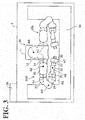
- FIG. 3 is a top view of the two-arm robot 10 schematically illustrating a configuration and an arrangement of the two-arm robot 10.
- the two-arm robot 10 is installed in a safety cabinet 5.
- a work table 5a is also disposed in the safety cabinet 5.
- the robot controller 50 is disposed outside the safety cabinet 5.
- the safety cabinet 5 defines an internal space that may be negatively pressurized. By negatively pressurizing the internal space, reagents used in fields such as the biomedical field are kept within the safety cabinet 5 even if the reagents are vaporized. It is also possible to provide in the safety cabinet 5 a misting mechanism to spray the two-arm robot 10 with a cleaning solution such as hydrogen peroxide solution so as to remove a reagent(s) off the two-arm robot 10.
- a cleaning solution such as hydrogen peroxide solution
- the work table 5a is for specimen-processing tools to rest on.
- the specimen-processing tools are used when the two-arm robot 10 performs specimen processing such as injection and agitation of reagents, and removal of cells.
- Examples of the specimen processing tools include, but are not limited to, the spatula 100, the culture vessel 200, test tubes, pipettes, droppers, spoons, and agitators.
- the specimen processing tools may be placed directly on the work table 5a or may be placed on a jig placed on the work table 5a (for example, spatula stand).
- the two-arm robot 10 includes a base 11, a body 12, a right arm 20R, and a left arm 20L.
- the base 11 is fixed to a surface such as the floor surface of the safety cabinet 5.
- the body 12 has a base end fixed to the base 11 and a distal end connected to the right arm 20R and the left arm 20L.
- the body 12 also includes swing axis A0, about which an upper portion of the body 12 swings laterally.
- each of the right arm 20R and the left arm 20L is a multi-articular robot with seven axes that include a redundant axis.
- the use of a multi-articular robot having a redundant axis ensures more accurate reproduction of details of work performed by an operator.
- the hands 30 are mounted on the distal ends of the right arm 20R and the left arm 20L.
- Each of the hands 30 has a holding mechanism implemented by a movable claw. It is noted that the holding mechanism will not be limited to gripping; any other manner of holding is possible such as adsorbing.
- the right arm 20R includes, in increasing order of distance from the base end, a first arm 21, a second arm 22, a third arm 23, a fourth arm 24, a fifth arm 25, a sixth arm 26, and a seventh arm 27.
- the left arm 20L has an approximately similar configuration to the configuration of the right arm 20R and therefore will not be elaborated here.
- the first arm 21 has its base end supported by the body 12 and is turnable about first axis A1.
- the second arm 22 has its base end supported by the distal end of the first arm 21 and is swingable about second axis A2.
- the third arm 23 has its base end supported by the distal end of the second arm 22 and is turnable about third axis A3.
- the fourth arm 24 has its base end supported by the distal end of the third arm 23 and is swingable about fourth axis A4.
- the fifth arm 25 has its base end supported by the distal end of the fourth arm 24 and is turnable about fifth axis A5.
- the sixth arm 26 has its base end supported by the distal end of the fifth arm 25 and is swingable about sixth axis A6.
- the seventh arm 27 has its base end supported by the distal end of the sixth arm 26 and is turnable about seventh axis A7.
- the hand 30 is supported by the distal end of the seventh arm 27.
- swing found in “swingable” in the above description refers to a movement that involves changes in the angle formed by adjoining arms.
- turn found in “turnable” refers to a relative movement that does not involve changes in the angle formed by adjoining arms.
- the two-arm robot 10 causes the right arm 20R and the left arm 20L to cooperate with each other to perform the removal operation illustrated in FIG. 1 with, for example, the hand 30 of the right arm 20R holding the spatula 100 and the hand 30 of the left arm 20L holding the culture vessel 200.
- This configuration makes the removal operation on the circumferential side 201a more reliable and more accurate.
- the two-arm robot 10 may hold one of the spatula 100 and the culture vessel 200, with the other one of the spatula 100 and the culture vessel 200 being fixed to the work table 5a or anywhere else to perform the removal operation.
- the robot controller 50 includes a controller 51 and a storage 52.
- the controller 51 includes a determiner 51 a, a switch 51b, and an operation controller 51c.
- the storage 52 stores classified information 52a and teaching information 52b.
- the robot controller 50 includes a computer and various circuits.
- the computer includes CPU (Central Processing Unit), ROM (Read Only Memory), RAM (Random Access Memory), HDD (Hard Disk Drive), and an input/output port.
- CPU Central Processing Unit
- ROM Read Only Memory
- RAM Random Access Memory
- HDD Hard Disk Drive
- the CPU of the computer reads programs stored in the ROM and executes the programs, and thus functions as the determiner 51a, the switch 51b, and the operation controller 51c of the controller 51.
- At least one or all of the determiner 51a, the switch 51 b, and the operation controller 51c may be made up of hardware such as ASIC (Application Specific Integrated Circuit) and FPGA (Field Programmable Gate Array).
- ASIC Application Specific Integrated Circuit
- FPGA Field Programmable Gate Array
- the storage 52 corresponds to the RAM and the HDD.
- the RAM and the HDD are capable of storing the classified information 52a and the teaching information 52b.
- the robot controller 50 may obtain the above-described programs and the various kinds of information from another computer connected to the robot controller 50 through a wired or wireless network or from a portable recording medium.
- the controller 51 controls the operation of the two-arm robot 10. Based on the classification of the cells that are on the culture vessel 200 and that are to undergo the removal operation, the determiner 51a determines whether to perform the removal operation in "outer-end leading posture" or “inner-end leading posture”.
- the determiner 51 a receives from the input device 60 an identifier or a similar indicator that indicates the classification of the cells. Then, the determiner 51a compares the received identifier with the classified information 52a stored in the storage 52.
- the classified information 52a is information that correlates the identifier with a posture (outer-end leading posture or inner-end leading posture).
- the determiner 51a searches the classified information 52a for the received identifier to find out which posture, outer-end leading posture or inner-end leading posture, the received identifier is correlated with. Then, the determiner 51 a informs the switch 51 b of the posture found as a result of the search.
- Examples of the input device 60 include, but are not limited to, a terminal such as a pendant of the robot controller 50, an input device such as a keyboard and a touch panel display, and a computer connected to the robot controller 50 through a wire or wirelessly.
- the input device 60 may be a bar code scanner to read a bar code that is attached to the culture vessel 200 and that indicates a cell classification.
- the input device 60 may be omitted.
- the determiner 51a may determine which posture, outer-end leading posture or inner-end leading posture, to use with respect to a plurality of culture vessels 200 according to a predetermined order. It will be readily appreciated that either outer-end leading posture or inner-end leading posture alone may be used with respect to the plurality of culture vessels 200.
- the switch 51b switches the order of "jobs" of the teaching information 52b.
- the teaching information 52b contains "jobs" that constitute a program defining a movement path for the two-arm robot 10.
- the program is prepared during teaching the two-arm robot 10 how to move.
- the switch 51 b switches the order of the jobs by putting the removal operation on the internal side after the removal operation on the circumferential side.
- the switch 51b switches the order of the jobs by putting the removal operation on the circumferential side after the removal operation on the internal side.
- the operation controller 51 c instructs the actuators (not illustrated) built in the joints of the two-arm robot 10 to implement a desired posture of the two-arm robot 10.
- the operation controller 51 c also improves the accuracy of the operation performed by the two-arm robot 10 by, for example, performing feedback control using encoder values obtained from the actuators.
- FIG. 4A schematically illustrates a removal operation on the circumferential side 201 a in outer-end leading posture.
- FIG. 4B schematically illustrates an removal operation on the internal side 201b in outer-end leading posture. It is noted that FIGs. 4A and 4B are top views of the culture vessel 200, as seen from the open side of the culture vessel 200, that is, from the Z-axis positive direction.
- the removal operation on the circumferential side 201 a of the culture surface 201 in outer-end leading posture is first performed on the circumferential side 201 a of the culture surface 201 as illustrated in FIG. 4A , and then performed on the internal side 201b of the culture surface 201 as illustrated in FIG. 4B .
- the second end of the blade 102 (the end nearer the center C) is displaced clockwise at an angle of ⁇ from the radial direction of the culture vessel 200 relative to the first end of the blade 102 (the end on the surrounding wall 202), so that the blade 102 is inclined clockwise at an angle of ⁇ .
- the spatula 100 makes one revolution from the start position S to the start position S while keeping the blade 102 inclined at an angle of ⁇ .
- posture 102a is illustrated in broken lines in FIG. 4A indicating a posture of the blade 102 moved clockwise by 90 degrees from the start position S.
- cells removed by the blade 102 are moved in cell movement direction 502.
- the cell movement direction 502 is toward the internal side 201 b of the culture surface 201.
- the removed cells move in the cell movement direction 502 along the blade 102 and end up being collected on the internal side 201 b of the culture surface 201. Even if the cells are fragile or difficult to remove, the above configuration enables the cells to be collected on the internal side 201 b with no or minimized damage to the cells.
- the removal operation on the circumferential side 201a of the culture surface 201 starts at the start position S illustrated in FIG. 4A and makes the spatula 100 make one revolution clockwise to return to the start position S. That is, the start position S is also an end position of the removal operation. Making one revolution in the removal operation in this manner makes the removal operation on the circumferential side 201a more reliable.
- the removal operation on the circumferential side 201a of the culture surface 201 makes the spatula 100 make one revolution (360 degrees) along the circumference of the culture surface 201, it is possible to make the spatula 100 make more than one revolution. Making more than one revolution makes the cell removal on the circumferential side 201a of the culture surface 201 even more reliable.
- the removal operation on the circumferential side 201a of the culture surface 201 in outer-end leading posture is followed by the removal operation on the internal side 201b of the culture surface 201 illustrated in FIG. 4B .
- the removal operation on the internal side 201b first makes the spatula 100 move approximately straight in forward direction 511, in which the spatula 100 moves, with the blade 102 perpendicular to the forward direction 511. This operation is performed a plurality of times with the start position of each operation being displaced in the X-axis negative direction. While in FIG. 4B the removal operation on the internal side 201b is performed three times, it is possible to optimize the number of removal operations based on the area of the culture surface 201 of the culture vessel 200 or the length of the blade 102 of the spatula 100.
- forward directions 511, 512, and 513 are toward the end point of each removal operation on the circumferential side 201 a, that is, toward start point S illustrated in FIG. 4B .
- Performing the removal operations on the internal side 201b in the forward directions 511, 512, and 513 makes cell collection more efficient. While in this embodiment each removal operation on the internal side 201b makes the spatula 100 move approximately straight in the forward directions 511, 512, and 513, the path of the removal operation on the internal side 201b will not be limited to the above-described linear path. Other possible examples of the path include, but are not limited to, a curved path and a combination of a linear path and a curve path.
- the end position, 102b, of the removal operation performed in the forward direction 511 is illustrated in FIG. 4B .
- the end position 102b is within the region covered by the removal operation on the circumferential side 201a of the culture surface 201.
- a second removal operation on the internal side 201b makes the spatula 100 move in the forward direction 512, similarly to the movement in the forward direction 511.
- the range covered by the removal operation performed by the blade 102 in the forward direction 512 overlaps the range covered by the removal operation performed by the blade 102 in the forward direction 511. This configuration makes the cells on the internal side 201 b more reliably removed.
- a third removal operation is performed on the internal side 201b in the forward direction 513.
- the end position, 102c, of the removal operation performed in the forward direction 513 is illustrated in FIG. 4B .
- the removal operation on the internal side 201b illustrated in FIG. 4B is performed. This configuration ensures that cells that are fragile or difficult to remove are collected to one position with no or minimized damage to the cells.
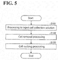
- FIG. 5 is a flowchart of a procedure for processings performed by the specimen processing system 1.
- the two-arm robot 10 injects a cell collection solution into the culture vessel 200 (step S101).
- the two-arm robot 10 holds a dropper in the hand 30 of one arm of the two-arm robot 10 and holds the culture vessel 200 in the hand 30 of the other arm of the two-arm robot 10. Then, the two-arm robot 10 makes the dropper suck the cell collection solution and inject the sucked cell collection solution into the culture vessel 200.
- the two-arm robot 10 performs cell removal processing (step S102).
- the two-arm robot 10 causes its arms to cooperate with each other to perform the cell removal processing with the one arm replacing the dropper with the spatula 100. Details of the processing at step S102 will be described later by referring to FIG. 6 .
- the two-arm robot 10 performs sucking processing with respect to the cells removed at step S102, and thus the processings end.
- the two-arm robot 10 replaces the spatula 100 with a dropper to suck the cells collected at one position on the culture vessel 200. Then, the two-arm robot 10 causes the dropper to discharge the sucked cells into a test tube.
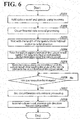
- FIG. 6 is a flowchart of a procedure for the cell removal processing.
- the two-arm robot 10 holds the culture vessel 200 and the spatula 100 respectively by the two arms (step S201).
- the two-arm robot 10 starts the removal processing on the circumferential side 201 a of the culture surface 201 illustrated in FIG. 4A (step S202).
- the two-arm robot 10 waits with the length of the blade 102 of the spatula 100 inclined relative to the radial direction of the culture vessel 200 (step S203). Specifically, the spatula 100 is kept in outer-end leading posture.
- the two-arm robot 10 presses the spatula 100 against the bottom of the culture vessel 200 (against the culture surface 201) (step S204). Then, the two-arm robot 10 moves the spatula 100 along the circumference of the culture vessel 200 while keeping the angle of the spatula 100 relative to the circumference of the culture vessel 200 (step S205).
- the specimen processing system 1 determines whether the spatula 100 has made one revolution along the circumference of the culture vessel 200 (step S206). When the specimen processing system 1 determines that the spatula 100 has not made one revolution (No at step S206 No), the specimen processing system 1 repeats the determination processing at step S206. When the specimen processing system I determines that the spatula 100 has made one revolution (Yes at step S206), the specimen processing system 1 ends the circumferential-side removal processing (step S207).
- the two-arm robot 10 performs, in the direction toward the start position S (see FIG. 4B ), the removal processing on the internal side 201 b of the culture surface 201, as illustrated in FIG. 4B (step S208), and the processings end.
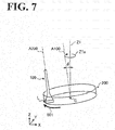
- FIG. 7 illustrates a cooperation between the two arms of the two-arm robot 10. It the following description, the two-arm robot 10 holds the spatula 100 in the hand 30 of one arm and holds the culture vessel 200 in the hand 30 of the other arm.
- the removal operation on the circumferential side described in FIG. 4A is performed while the culture vessel 200 is inclined in different directions.
- the arm of the two-arm robot 10 holding the culture vessel 200 changes the inclination of the culture vessel 200 to keep lowermost point L of the culture vessel 200 more frontward than the spatula 100 in the forward direction 501, in which the spatula 100 moves.
- the one arm holding the spatula 100 performs the operation illustrated in FIG. 1 , making the spatula 100 make orbital rotation about the center line A100 of the culture vessel 200 while rotating itself about the rotation axis A200. Simultaneously, the other arm changes the inclination of the culture vessel 200.
- the culture vessel 200 circumnutates in direction Z1a with the center line A100 of the culture vessel 200 inclined at an angle of ⁇ relative to line Z1, which is parallel to Z axis. This ensures that cells removed from the culture surface 201 or cells floating off the culture surface 201 are kept in front of the spatula 100 in the forward direction 501, resulting in improved cell collection effciency.
- Angle ⁇ may be any angle greater than zero degree.
- FIG. 8A schematically illustrates the removal operation on the internal side in inner-end leading posture.
- FIG. 8B schematically illustrates the removal operation on the circumferential side in inner-end leading posture.
- FIGs. 8A and 8B are top views of the culture vessel 200, as seen from the open side of the culture vessel 200, that is, from the Z-axis positive direction.
- the removal operation on the internal side 201b of the culture surface 201 is similar to the removal operation on the internal side 201 b illustrated in FIG. 4B .
- the internal side 201b is defined by a rectangle that corresponds to the region covered by the internal-side removal operation.
- the internal-side removal operation illustrated in FIG. 8A is similar to the internal-side removal operation illustrated FIG. 4B and will not be elaborated here.
- the removal operation on the internal side 201b of the culture surface 201 is followed by the removal operation on the circumferential side 201a of the culture surface 201, as illustrated in FIG. 8B .
- the second end of the blade 102 (the end nearer the center C) is displaced anti-clockwise at an angle of ⁇ from the radial direction of the culture vessel 200 relative to the first end of the blade 102 (the end on the surrounding wall 202), so that the blade 102 is inclined anti-clockwise at an angle of ⁇ .
- the spatula 100 makes one revolution from the start position S to the start position S while keeping the blade 102 inclined at an angle of ⁇ .
- the posture 102a is illustrated in broken lines in FIG. 8B indicating a posture of the blade 102 moved clockwise by 90 degrees from the start position S.
- cells removed by the blade 102 are moved in cell movement direction 502.
- the cell movement direction 502 is toward the circumferential side 201a of the culture surface 201. That is, the removed cells move in the cell movement direction 502 along the blade 102 and end up being collected on or near the surrounding wall 202 in front of the blade 102 in the forward direction 501. This configuration improves efficiency in collecting cells to one position.
- the removal operation on the circumferential side 201 a of the culture surface 201 starts at the start position S illustrated in FIG. 8B and makes the spatula 100 make one revolution clockwise to return to the start position S. That is, the start position S is also an end position of the removal operation.
- the removal operation on the circumferential side 201a of the culture surface 201 makes the spatula 100 make one revolution (360 degrees) along the circumference of the culture surface 201, it is possible to make the spatula 100 make more than one revolution. Making more than one revolution makes the cell removal on the circumferential side 201a of the culture surface 201 even more reliable.
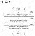
- FIG. 9 is a flowchart of a procedure for the cell removal processing in inner-end leading posture.
- the two-arm robot 10 holds the culture vessel 200 and the spatula 100 respectively by the two arms (step S301).
- the two-arm robot 10 performs the internal-side removal processing in the direction toward the start position S (see FIG. 8B ) of the circumferential-side removal processing (step S302). Then, with the spatula 100 taking inner-end leading posture, the two-arm robot 10 performs one revolution of the circumferential-side removal processing from the start position S (step S303), and the processings end. Details of the procedure at step S303 are similar to the procedure at step S202 through step S207 illustrated in FIG. 6 and will not be elaborated here.
- the specimen processing system 1 includes the culture vessel 200, the spatula 100, the robot 10, and the robot controller 50.
- the culture vessel 200 is open on the top surface of the culture vessel 200 and includes the culture surface 201, which has a circular shape and on which cells are culturable.
- the spatula 100 includes the blade 102, which removes the cells off the culture surface 201.
- the robot 10 includes the hands 30, which are capable of holding at least one of the culture vessel 200 and the spatula 100.
- the robot controller 50 controls the robot 10.
- the robot controller 50 includes the operation controller 51c.
- the operation controller 51c controls the robot 10 to perform a first operation. In the first operation, the robot 10 moves the spatula 100 relative to the culture vessel 200 with the first end of the blade 102 on the circumference of the culture surface 201 so as to remove cells on the circumferential side 201a of the culture surface 201. Then, the operation controller 51 c controls the robot 10 to perform a second operation. In the second operation, the robot 10 moves the spatula 100 relative to the culture vessel 200 so as to remove cells on the internal side 201 b of the culture surface 201.
- the specimen processing system 1 makes a gap difficult to occur between the blade 102 of the spatula 100 and the culture vessel 200, and thus improves cell collection efficiency. Also, the specimen processing system 1 performs the removal operation on the circumferential side 201a of the culture surface 201 using the spatula 100 in outer-end leading posture. This configuration improves efficiency in collecting cells with no or minimized damage to the cells even if the cells are fragile.
- spatula 100 moves clockwise relative to the culture vessel 200 in plan view of the culture vessel 200, the spatula 100 may move anti-clockwise.
Landscapes
- Engineering & Computer Science (AREA)
- Chemical & Material Sciences (AREA)
- Health & Medical Sciences (AREA)
- Life Sciences & Earth Sciences (AREA)
- Bioinformatics & Cheminformatics (AREA)
- Organic Chemistry (AREA)
- Wood Science & Technology (AREA)
- Zoology (AREA)
- Biotechnology (AREA)
- Biochemistry (AREA)
- General Health & Medical Sciences (AREA)
- Genetics & Genomics (AREA)
- Sustainable Development (AREA)
- Microbiology (AREA)
- Biomedical Technology (AREA)
- General Engineering & Computer Science (AREA)
- Analytical Chemistry (AREA)
- Robotics (AREA)
- Clinical Laboratory Science (AREA)
- Computer Hardware Design (AREA)
- Physics & Mathematics (AREA)
- General Physics & Mathematics (AREA)
- Immunology (AREA)
- Pathology (AREA)
- Molecular Biology (AREA)
- Mechanical Engineering (AREA)
- Apparatus Associated With Microorganisms And Enzymes (AREA)
- Measuring Or Testing Involving Enzymes Or Micro-Organisms (AREA)
Description
- The present invention relates to a specimen processing system and a method for processing a specimen.
- In biomedical fields, robots are used in specimen processing such as injection, agitation, and separation of reagents.
- Japanese Unexamined Patent Application Publication No.
2013-009618 - The contents of Japanese Unexamined Patent Application Publication No.
2013-009618 - Japanese Unexamined Patent Application Publication No.
2013-009618 - One aspect of an embodiment has been made in view of the above-described circumstances, and it is an object of the present disclosure to provide a specimen processing system and a method for processing a specimen that improve cell collection efficiency.
- According to one aspect of the present disclosure, a specimen processing system includes a culture vessel, a spatula, a robot, and a robot controller. The culture vessel is open on a top surface of the culture vessel and includes a culture surface which has a circular shape and on which cells are culturable. The spatula includes a blade to remove the cells off the culture surface. The robot includes a hand to hold at least one of the culture vessel and the spatula. The robot controller is configured to control the robot and includes an operation controller. The operation controller is configured to control the robot to perform: a first operation to move the spatula relative to the culture vessel with a first end of the blade on a circumference of the culture surface so as to remove first cells among the cells on the culture surface that are nearer the circumference of the culture surface; and a second operation to move the spatula relative to the culture vessel so as to remove second cells among the cells on the culture surface that are inner than the first cells on the culture surface.
- The one aspect of the embodiment provides a specimen processing system and a method for processing a specimen that improve cell collection efficiency.
- A more complete appreciation of the present disclosure and many of the attendant advantages thereof will be readily obtained as the same becomes better understood by reference to the following detailed description when considered in connection with the accompanying drawings, wherein:
-
FIG. 1 is a schematic illustrating a method for processing a specimen; -
FIG. 2 is a block diagram illustrating a configuration of a specimen processing system; -
FIG. 3 is a top view of a two-arm robot schematically illustrating a configuration and an arrangement of the two-arm robot; -
FIG. 4A schematically illustrates a removal operation on a circumferential side in outer-end leading posture; -
FIG. 4B schematically illustrates a removal operation on an internal side in outer-end leading posture; -
FIG. 5 is a flowchart of a procedure for processings performed by the specimen processing system; -
FIG. 6 is a flowchart of a procedure for cell removal processing; -
FIG. 7 illustrates a cooperation between two arms of a two-arm robot; -
FIG. 8A schematically illustrates a removal operation on the internal side in inner-end leading posture; -
FIG. 8B schematically illustrates a removal operation on the circumferential side in inner-end leading posture; and -
FIG. 9 is a flowchart of a procedure for cell removal processing in inner-end leading posture. - The embodiments will now be described with reference to the accompanying drawings, wherein like reference numerals designate corresponding or identical elements throughout the various drawings. In the following description, what is called a two-arm robot has its two arms cooperate with each other to perform specimen processing. A two-arm robot, however, is not intended in a limiting sense; it is also possible to use a single-arm robot. It is noted that the following embodiments are provided for exemplary purposes only and are not intended in a limiting sense.
- Also in the following description, the terms "parallel", "perpendicular", and "vertical" may occasionally be used to not only mean "parallel", "perpendicular", and "vertical", respectively, in a strict sense but also mean "parallel", "perpendicular", and "vertical", respectively, in an approximate sense. That is, the terms "parallel", "perpendicular", and "vertical" are used taking into consideration production-related, installation-related, processing-related, and detection-related tolerances and errors.
- First, a method according to this embodiment for processing a specimen will be described by referring to
FIG. 1. FIG. 1 is a schematic illustrating the method according to this embodiment for processing a specimen. For ease of description,FIG. 1 illustrates a three-dimensional orthogonal coordinate system including X axis, Y axis, and Z axis. Z axis has its positive direction oriented in a vertically upward direction from the center C of aculture surface 201 of aculture vessel 200. X axis and Y axis are parallel to theculture surface 201. This orthogonal coordinate system may also be illustrated in some other drawings referred to in the following description. - As illustrated in
FIG. 1 , aspatula 100 is a cell scraper, for example, and includes ahandle 101 and ablade 102. Theblade 102 is disposed at one end of thehandle 101. Thehandle 101 is holdable by hands 30 (described later by referring toFIG. 3 ). Theblade 102 is made of an elastic material. When theblade 102 is pressed into full contact with theculture surface 201 and moved in aforward direction 501, in which thespatula 100 moves, theblade 102 bends in the backward direction opposite to theforward direction 501 while keeping close contact with theculture surface 201. Theblade 102 may have any shape insofar as full contact with theculture surface 201 is established. Thehandle 101 and theblade 102 may be separate parts or an integral part. - The
culture vessel 200 is a dish, for example, and includes theculture surface 201 and a surroundingwall 202. Theculture surface 201 has a circular shape. On theculture surface 201, cells are cultured. The surroundingwall 202 has a hollow cylindrical shape standing on the circumference of theculture surface 201. The top surface of the culture vessel 200 (the surface in the Z-axis positive direction) is open. - As illustrating
FIG. 1 , reference letter S denotes the start position of the removal operation along the circumference of theculture surface 201, reference letter B denotes an imaginary line extended from theblade 102, reference letter R denotes an imaginary radial-direction line connecting between center C and start position S, and reference letter α denotes the angle formed by line B and line R. Start position S is the position at which a first end of theblade 102 contacts with the circumference of the culture surface 201 (the inner side of the surrounding wall 202). - By holding the
spatula 100 and theculture vessel 200 using the hands 30, described later, and moving thespatula 100 and theculture vessel 200 relative to each other, the above-described cell removal operation is performed. The method according to this embodiment for processing a specimen will be described in detail below. - As illustrated in
FIG. 1 , in the method according to this embodiment for processing a specimen, those cells that are nearer the circumference of theculture surface 201 of theculture vessel 200 are first to be removed with the length of theblade 102 of thespatula 100 inclined relative to line R. - In the embodiment of
FIG. 1 , in top view of theculture vessel 200, the length of the blade 102 (see line B) is inclined clockwise by angle α relative to line R, which is a radial line passing through the start position S. That is, in the embodiment ofFIG. 1 , the center C-side end of theblade 102 falls behind in the backward direction opposite to theforward direction 501. Thespatula 100 makes one revolution along the circumference of theculture surface 201 while keeping theblade 102 inclined at an angle of α. Angle α may be any angle greater than zero degree. - Specifically, as illustrated in
FIG. 1 , thespatula 100 makes orbital rotation about center line A100 of the culture vessel 200 (see direction Ala illustrated inFIG. 1 ) while rotating itself about rotation axis A200 (see direction A2a illustrated inFIG. 1 ). Here, thespatula 100 makes one rotation about itself per orbital rotation, and this enables the removal operation to be performed with theblade 102 inclined at an angle of α. - A conventional removal operation to remove cells nearer the circumference of the
culture surface 201 involves keeping angle α at 0 degree. That is, in the conventional removal operation, the length of theblade 102 is perpendicular to the circumference of theculture surface 201. This causes a portion of theblade 102 contacting the surroundingwall 202 to be deformed by frictional force, creating a gap between theblade 102 and the surroundingwall 202 and allowing removed cells to leak through the gap in the backward direction opposite to theforward direction 501. - In view of this situation, in the method according to this embodiment for processing a specimen, cells nearer the circumference of the
culture surface 201 are removed with the length of theblade 102 of thespatula 100 being inclined relative to theforward direction 501, as illustrated inFIG. 1 . This configuration eliminates or minimizes occurrence of a gap between theblade 102 and the surroundingwall 202, resulting in improved cell collection efficiency. - As illustrated in
FIG. 1 , a second end of the blade 102 (the end nearer the center C) is displaced from the radial direction of theculture vessel 200 relative to the first end of the blade 102 (the end on the surrounding wall 202) in the backward direction opposite to theforward direction 501. In the following description, this posture of thespatula 100 will be hereinafter referred to as "outer-end leading posture", and a removal operation performed in this posture will be hereinafter referred to as "removal operation in outer-end leading posture". The removal operation in outer-end leading posture will be detailed later by referring toFIG. 4A and other drawings. - It is noted that in the method according to this embodiment for processing a specimen, the removal operation may be performed with the
spatula 100 in such a posture that the second end of the blade 102 (the end nearer the center C) is displaced from the radial direction of theculture vessel 200 relative to the first end of the blade 102 (the end on the surrounding wall 202) in theforward direction 501. - In the following description, this posture of the
spatula 100 will be hereinafter referred to as "inner-end leading posture", and a removal operation performed in this posture will be hereinafter referred to as "removal operation in inner-end leading posture". The removal operation in inner-end leading posture will be detailed later by referring toFIG. 8A and other drawings. - By referring to
FIG. 2 , a configuration of aspecimen processing system 1 according to this embodiment will be described.FIG. 2 is a block diagram illustrating a configuration of thespecimen processing system 1. As illustrated inFIG. 2 , thespecimen processing system 1 includes a two-arm robot 10, arobot controller 50, and aninput device 60. The two-arm robot 10 and theinput device 60 are connected to therobot controller 50. As described later, theinput device 60 may be omitted. - The two-
arm robot 10 includes a right arm and a left arm that are independent of each other. In response to an instruction(s) from therobot controller 50, the two-arm robot 10 performs specimen processing. The two-arm robot 10 is installed in a workroom isolated from the environment to perform the specimen processing. - By referring to
FIG. 3 , an exemplary configuration and an exemplary arrangement of the two-arm robot 10 will be described.FIG. 3 is a top view of the two-arm robot 10 schematically illustrating a configuration and an arrangement of the two-arm robot 10. As illustrated inFIG. 3 , the two-arm robot 10 is installed in asafety cabinet 5. A work table 5a is also disposed in thesafety cabinet 5. Therobot controller 50 is disposed outside thesafety cabinet 5. - The
safety cabinet 5 defines an internal space that may be negatively pressurized. By negatively pressurizing the internal space, reagents used in fields such as the biomedical field are kept within thesafety cabinet 5 even if the reagents are vaporized. It is also possible to provide in thesafety cabinet 5 a misting mechanism to spray the two-arm robot 10 with a cleaning solution such as hydrogen peroxide solution so as to remove a reagent(s) off the two-arm robot 10. - The work table 5a is for specimen-processing tools to rest on. The specimen-processing tools are used when the two-
arm robot 10 performs specimen processing such as injection and agitation of reagents, and removal of cells. Examples of the specimen processing tools include, but are not limited to, thespatula 100, theculture vessel 200, test tubes, pipettes, droppers, spoons, and agitators. The specimen processing tools may be placed directly on the work table 5a or may be placed on a jig placed on the work table 5a (for example, spatula stand). - The two-
arm robot 10 includes abase 11, abody 12, aright arm 20R, and aleft arm 20L. Thebase 11 is fixed to a surface such as the floor surface of thesafety cabinet 5. Thebody 12 has a base end fixed to thebase 11 and a distal end connected to theright arm 20R and theleft arm 20L. Thebody 12 also includes swing axis A0, about which an upper portion of thebody 12 swings laterally. - As illustrated in
FIG. 3 , each of theright arm 20R and theleft arm 20L is a multi-articular robot with seven axes that include a redundant axis. The use of a multi-articular robot having a redundant axis ensures more accurate reproduction of details of work performed by an operator. On the distal ends of theright arm 20R and theleft arm 20L, the hands 30 are mounted. Each of the hands 30 has a holding mechanism implemented by a movable claw. It is noted that the holding mechanism will not be limited to gripping; any other manner of holding is possible such as adsorbing. - Also as illustrated in
FIG. 3 , theright arm 20R includes, in increasing order of distance from the base end, afirst arm 21, asecond arm 22, athird arm 23, afourth arm 24, a fifth arm 25, a sixth arm 26, and a seventh arm 27. Theleft arm 20L has an approximately similar configuration to the configuration of theright arm 20R and therefore will not be elaborated here. - The
first arm 21 has its base end supported by thebody 12 and is turnable about first axis A1. Thesecond arm 22 has its base end supported by the distal end of thefirst arm 21 and is swingable about second axis A2. Thethird arm 23 has its base end supported by the distal end of thesecond arm 22 and is turnable about third axis A3. Thefourth arm 24 has its base end supported by the distal end of thethird arm 23 and is swingable about fourth axis A4. - The fifth arm 25 has its base end supported by the distal end of the
fourth arm 24 and is turnable about fifth axis A5. The sixth arm 26 has its base end supported by the distal end of the fifth arm 25 and is swingable about sixth axis A6. The seventh arm 27 has its base end supported by the distal end of the sixth arm 26 and is turnable about seventh axis A7. The hand 30 is supported by the distal end of the seventh arm 27. - The term "swing" found in "swingable" in the above description refers to a movement that involves changes in the angle formed by adjoining arms. The term "turn" found in "turnable" refers to a relative movement that does not involve changes in the angle formed by adjoining arms.
- The two-
arm robot 10 causes theright arm 20R and theleft arm 20L to cooperate with each other to perform the removal operation illustrated inFIG. 1 with, for example, the hand 30 of theright arm 20R holding thespatula 100 and the hand 30 of theleft arm 20L holding theculture vessel 200. This configuration makes the removal operation on thecircumferential side 201a more reliable and more accurate. In another possible embodiment, the two-arm robot 10 may hold one of thespatula 100 and theculture vessel 200, with the other one of thespatula 100 and theculture vessel 200 being fixed to the work table 5a or anywhere else to perform the removal operation. - Referring again to
FIG. 2 , therobot controller 50 will be described. Therobot controller 50 includes acontroller 51 and astorage 52. Thecontroller 51 includes adeterminer 51 a, aswitch 51b, and anoperation controller 51c. Thestorage 52 stores classifiedinformation 52a andteaching information 52b. - The
robot controller 50 includes a computer and various circuits. The computer includes CPU (Central Processing Unit), ROM (Read Only Memory), RAM (Random Access Memory), HDD (Hard Disk Drive), and an input/output port. - The CPU of the computer reads programs stored in the ROM and executes the programs, and thus functions as the
determiner 51a, theswitch 51b, and theoperation controller 51c of thecontroller 51. - Alternatively, at least one or all of the
determiner 51a, theswitch 51 b, and theoperation controller 51c may be made up of hardware such as ASIC (Application Specific Integrated Circuit) and FPGA (Field Programmable Gate Array). - The
storage 52 corresponds to the RAM and the HDD. The RAM and the HDD are capable of storing theclassified information 52a and theteaching information 52b. In another possible embodiment, therobot controller 50 may obtain the above-described programs and the various kinds of information from another computer connected to therobot controller 50 through a wired or wireless network or from a portable recording medium. - The
controller 51 controls the operation of the two-arm robot 10. Based on the classification of the cells that are on theculture vessel 200 and that are to undergo the removal operation, thedeterminer 51a determines whether to perform the removal operation in "outer-end leading posture" or "inner-end leading posture". - Specifically, the
determiner 51 a receives from theinput device 60 an identifier or a similar indicator that indicates the classification of the cells. Then, thedeterminer 51a compares the received identifier with theclassified information 52a stored in thestorage 52. Theclassified information 52a is information that correlates the identifier with a posture (outer-end leading posture or inner-end leading posture). - The
determiner 51a searches theclassified information 52a for the received identifier to find out which posture, outer-end leading posture or inner-end leading posture, the received identifier is correlated with. Then, thedeterminer 51 a informs theswitch 51 b of the posture found as a result of the search. - Examples of the
input device 60 include, but are not limited to, a terminal such as a pendant of therobot controller 50, an input device such as a keyboard and a touch panel display, and a computer connected to therobot controller 50 through a wire or wirelessly. In another possible embodiment, theinput device 60 may be a bar code scanner to read a bar code that is attached to theculture vessel 200 and that indicates a cell classification. - In still another possible embodiment, the
input device 60 may be omitted. When theinput device 60 is omitted, thedeterminer 51a may determine which posture, outer-end leading posture or inner-end leading posture, to use with respect to a plurality ofculture vessels 200 according to a predetermined order. It will be readily appreciated that either outer-end leading posture or inner-end leading posture alone may be used with respect to the plurality ofculture vessels 200. - Based on the determination made by the
determiner 51a, theswitch 51b switches the order of "jobs" of theteaching information 52b. Theteaching information 52b contains "jobs" that constitute a program defining a movement path for the two-arm robot 10. The program is prepared during teaching the two-arm robot 10 how to move. - When the cells nearer the circumference of the
culture surface 201 are removed in outer-end leading posture, theswitch 51 b switches the order of the jobs by putting the removal operation on the internal side after the removal operation on the circumferential side. When the cells nearer the circumference of theculture surface 201 are removed in inner-end leading posture, theswitch 51b switches the order of the jobs by putting the removal operation on the circumferential side after the removal operation on the internal side. This configuration shortens the time necessary to generate the "jobs" and simplifies the work necessary to generate the "jobs". - Based on the
teaching information 52b having the order of jobs switched by theswitch 51 b, theoperation controller 51 c instructs the actuators (not illustrated) built in the joints of the two-arm robot 10 to implement a desired posture of the two-arm robot 10. Theoperation controller 51 c also improves the accuracy of the operation performed by the two-arm robot 10 by, for example, performing feedback control using encoder values obtained from the actuators. - By referring to
FIGs. 4A and 4B , the removal operation in outer-end leading posture performed by thespecimen processing system 1 will be described.FIG. 4A schematically illustrates a removal operation on thecircumferential side 201 a in outer-end leading posture.FIG. 4B schematically illustrates an removal operation on theinternal side 201b in outer-end leading posture. It is noted thatFIGs. 4A and 4B are top views of theculture vessel 200, as seen from the open side of theculture vessel 200, that is, from the Z-axis positive direction. - Also as illustrated in
FIGs. 4A and 4B , the removal operation on thecircumferential side 201 a of theculture surface 201 in outer-end leading posture is first performed on thecircumferential side 201 a of theculture surface 201 as illustrated inFIG. 4A , and then performed on theinternal side 201b of theculture surface 201 as illustrated inFIG. 4B . - As illustrated in
FIG. 4A , in the removal operation on thecircumferential side 201 a of theculture surface 201 in outer-end leading posture, which is performed in theforward direction 501, the second end of the blade 102 (the end nearer the center C) is displaced clockwise at an angle of α from the radial direction of theculture vessel 200 relative to the first end of the blade 102 (the end on the surrounding wall 202), so that theblade 102 is inclined clockwise at an angle of α. - Then, the
spatula 100 makes one revolution from the start position S to the start position S while keeping theblade 102 inclined at an angle of α. For reference purposes,posture 102a is illustrated in broken lines inFIG. 4A indicating a posture of theblade 102 moved clockwise by 90 degrees from the start position S. - In the removal operation with the
blade 102 taking outer-end leading posture, cells removed by theblade 102 are moved incell movement direction 502. In the embodiment ofFIG. 4A , thecell movement direction 502 is toward theinternal side 201 b of theculture surface 201. - That is, instead of remaining on the forward side of the
blade 102 in theforward direction 501, the removed cells move in thecell movement direction 502 along theblade 102 and end up being collected on theinternal side 201 b of theculture surface 201. Even if the cells are fragile or difficult to remove, the above configuration enables the cells to be collected on theinternal side 201 b with no or minimized damage to the cells. - The removal operation on the
circumferential side 201a of theculture surface 201 starts at the start position S illustrated inFIG. 4A and makes thespatula 100 make one revolution clockwise to return to the start position S. That is, the start position S is also an end position of the removal operation. Making one revolution in the removal operation in this manner makes the removal operation on thecircumferential side 201a more reliable. - While in this embodiment the removal operation on the
circumferential side 201a of theculture surface 201 makes thespatula 100 make one revolution (360 degrees) along the circumference of theculture surface 201, it is possible to make thespatula 100 make more than one revolution. Making more than one revolution makes the cell removal on thecircumferential side 201a of theculture surface 201 even more reliable. - The removal operation on the
circumferential side 201a of theculture surface 201 in outer-end leading posture is followed by the removal operation on theinternal side 201b of theculture surface 201 illustrated inFIG. 4B . - The removal operation on the
internal side 201b first makes thespatula 100 move approximately straight inforward direction 511, in which thespatula 100 moves, with theblade 102 perpendicular to theforward direction 511. This operation is performed a plurality of times with the start position of each operation being displaced in the X-axis negative direction. While inFIG. 4B the removal operation on theinternal side 201b is performed three times, it is possible to optimize the number of removal operations based on the area of theculture surface 201 of theculture vessel 200 or the length of theblade 102 of thespatula 100. - As illustrated in
FIG. 4B ,forward directions circumferential side 201 a, that is, toward start point S illustrated inFIG. 4B . Performing the removal operations on theinternal side 201b in theforward directions internal side 201b makes thespatula 100 move approximately straight in theforward directions internal side 201b will not be limited to the above-described linear path. Other possible examples of the path include, but are not limited to, a curved path and a combination of a linear path and a curve path. - The range of the removal operation on the
internal side 201 b performed by theblade 102 overlaps the region covered by the removal operation on thecircumferential side 201a. This causes those cells, if any, that have escaped the removal operation on thecircumferential side 201 a to be reliably collected in the removal operations on theinternal side 201b. For reference purposes, the end position, 102b, of the removal operation performed in theforward direction 511 is illustrated inFIG. 4B . Theend position 102b is within the region covered by the removal operation on thecircumferential side 201a of theculture surface 201. - A second removal operation on the
internal side 201b makes thespatula 100 move in theforward direction 512, similarly to the movement in theforward direction 511. The range covered by the removal operation performed by theblade 102 in theforward direction 512 overlaps the range covered by the removal operation performed by theblade 102 in theforward direction 511. This configuration makes the cells on theinternal side 201 b more reliably removed. - In a manner similar to the manner in which the second removal operation has been performed on the
internal side 201b, a third removal operation is performed on theinternal side 201b in theforward direction 513. For reference purposes, the end position, 102c, of the removal operation performed in theforward direction 513 is illustrated inFIG. 4B . Thus, after the removal operation on thecircumferential side 201a in outer-end leading posture illustrated inFIG. 4A , the removal operation on theinternal side 201b illustrated inFIG. 4B is performed. This configuration ensures that cells that are fragile or difficult to remove are collected to one position with no or minimized damage to the cells. - By referring to
FIG. 5 , a procedure for processings performed by thespecimen processing system 1 will be described.FIG. 5 is a flowchart of a procedure for processings performed by thespecimen processing system 1. First, in response to an instruction from therobot controller 50, the two-arm robot 10 injects a cell collection solution into the culture vessel 200 (step S101). - For example, the two-
arm robot 10 holds a dropper in the hand 30 of one arm of the two-arm robot 10 and holds theculture vessel 200 in the hand 30 of the other arm of the two-arm robot 10. Then, the two-arm robot 10 makes the dropper suck the cell collection solution and inject the sucked cell collection solution into theculture vessel 200. - Next, the two-
arm robot 10 performs cell removal processing (step S102). For example, the two-arm robot 10 causes its arms to cooperate with each other to perform the cell removal processing with the one arm replacing the dropper with thespatula 100. Details of the processing at step S102 will be described later by referring toFIG. 6 . - At step S103, the two-
arm robot 10 performs sucking processing with respect to the cells removed at step S102, and thus the processings end. For example, the two-arm robot 10 replaces thespatula 100 with a dropper to suck the cells collected at one position on theculture vessel 200. Then, the two-arm robot 10 causes the dropper to discharge the sucked cells into a test tube. - By referring to
FIG. 6 , description will be made with regard to details of the procedure for the cell removal processing at step S102 described inFIG. 5 .FIG. 6 is a flowchart of a procedure for the cell removal processing. The two-arm robot 10 holds theculture vessel 200 and thespatula 100 respectively by the two arms (step S201). - Next, the two-
arm robot 10 starts the removal processing on thecircumferential side 201 a of theculture surface 201 illustrated inFIG. 4A (step S202). First, the two-arm robot 10 waits with the length of theblade 102 of thespatula 100 inclined relative to the radial direction of the culture vessel 200 (step S203). Specifically, thespatula 100 is kept in outer-end leading posture. - Then, at the start position S (see
FIG. 4A ), which is on the circumference of theculture vessel 200, the two-arm robot 10 presses thespatula 100 against the bottom of the culture vessel 200 (against the culture surface 201) (step S204). Then, the two-arm robot 10 moves thespatula 100 along the circumference of theculture vessel 200 while keeping the angle of thespatula 100 relative to the circumference of the culture vessel 200 (step S205). - Next, the
specimen processing system 1 determines whether thespatula 100 has made one revolution along the circumference of the culture vessel 200 (step S206). When thespecimen processing system 1 determines that thespatula 100 has not made one revolution (No at step S206 No), thespecimen processing system 1 repeats the determination processing at step S206. When the specimen processing system I determines that thespatula 100 has made one revolution (Yes at step S206), thespecimen processing system 1 ends the circumferential-side removal processing (step S207). - Then, the two-
arm robot 10 performs, in the direction toward the start position S (seeFIG. 4B ), the removal processing on theinternal side 201 b of theculture surface 201, as illustrated inFIG. 4B (step S208), and the processings end. - By referring to
FIG. 7 , an exemplary cooperation between the two arms of the two-arm robot 10 will be described.FIG. 7 illustrates a cooperation between the two arms of the two-arm robot 10. It the following description, the two-arm robot 10 holds thespatula 100 in the hand 30 of one arm and holds theculture vessel 200 in the hand 30 of the other arm. - Also in
FIG. 7 , the removal operation on the circumferential side described inFIG. 4A is performed while theculture vessel 200 is inclined in different directions. As illustrated inFIG. 7 , the arm of the two-arm robot 10 holding theculture vessel 200 changes the inclination of theculture vessel 200 to keep lowermost point L of theculture vessel 200 more frontward than thespatula 100 in theforward direction 501, in which thespatula 100 moves. - Specifically, the one arm holding the
spatula 100 performs the operation illustrated inFIG. 1 , making thespatula 100 make orbital rotation about the center line A100 of theculture vessel 200 while rotating itself about the rotation axis A200. Simultaneously, the other arm changes the inclination of theculture vessel 200. - In the embodiment of
FIG. 7 , theculture vessel 200 circumnutates in direction Z1a with the center line A100 of theculture vessel 200 inclined at an angle of θ relative to line Z1, which is parallel to Z axis. This ensures that cells removed from theculture surface 201 or cells floating off theculture surface 201 are kept in front of thespatula 100 in theforward direction 501, resulting in improved cell collection effciency. Angle θ may be any angle greater than zero degree. - By referring to
FIGs. 8A and 8B , the removal operation in inner-end leading posture performed by thespecimen processing system 1 will be described.FIG. 8A schematically illustrates the removal operation on the internal side in inner-end leading posture.FIG. 8B schematically illustrates the removal operation on the circumferential side in inner-end leading posture.FIGs. 8A and 8B are top views of theculture vessel 200, as seen from the open side of theculture vessel 200, that is, from the Z-axis positive direction. - As illustrated in
FIGs. 8A and 8B , when thespatula 100 is in inner-end leading posture in the removal operation on thecircumferential side 201a of theculture surface 201, as illustrated inFIG. 8B , the removal operation on theinternal side 201b of theculture surface 201 illustrated inFIG. 8A is first to be performed, followed by the removal operation on thecircumferential side 201 a of theculture surface 201 in inner-end leading posture. - As illustrated in
FIG. 8A , the removal operation on theinternal side 201b of theculture surface 201 is similar to the removal operation on theinternal side 201 b illustrated inFIG. 4B . As illustrated inFIG. 8A , theinternal side 201b is defined by a rectangle that corresponds to the region covered by the internal-side removal operation. The internal-side removal operation illustrated inFIG. 8A is similar to the internal-side removal operation illustratedFIG. 4B and will not be elaborated here. - The removal operation on the
internal side 201b of theculture surface 201 is followed by the removal operation on thecircumferential side 201a of theculture surface 201, as illustrated inFIG. 8B . - As illustrated in
FIG. 8B , in the removal operation on thecircumferential side 201a of theculture surface 201 in inner-end leading posture, which is performed in theforward direction 501, the second end of the blade 102 (the end nearer the center C) is displaced anti-clockwise at an angle of β from the radial direction of theculture vessel 200 relative to the first end of the blade 102 (the end on the surrounding wall 202), so that theblade 102 is inclined anti-clockwise at an angle of β. - Then, the
spatula 100 makes one revolution from the start position S to the start position S while keeping theblade 102 inclined at an angle of β. For reference purposes, theposture 102a is illustrated in broken lines inFIG. 8B indicating a posture of theblade 102 moved clockwise by 90 degrees from the start position S. - In the removal operation with the
blade 102 taking inner-end leading posture, cells removed by theblade 102 are moved incell movement direction 502. In the embodiment ofFIG. 8B , thecell movement direction 502 is toward thecircumferential side 201a of theculture surface 201. That is, the removed cells move in thecell movement direction 502 along theblade 102 and end up being collected on or near the surroundingwall 202 in front of theblade 102 in theforward direction 501. This configuration improves efficiency in collecting cells to one position. - The removal operation on the
circumferential side 201 a of theculture surface 201 starts at the start position S illustrated inFIG. 8B and makes thespatula 100 make one revolution clockwise to return to the start position S. That is, the start position S is also an end position of the removal operation. - While in this embodiment the removal operation on the
circumferential side 201a of theculture surface 201 makes thespatula 100 make one revolution (360 degrees) along the circumference of theculture surface 201, it is possible to make thespatula 100 make more than one revolution. Making more than one revolution makes the cell removal on thecircumferential side 201a of theculture surface 201 even more reliable. - By referring to
FIG. 9 , description will be made with regard to details of the procedure for the cell removal processing at step S102 described inFIG. 5 in the case of theblade 102 taking inner-end leading posture.FIG. 9 is a flowchart of a procedure for the cell removal processing in inner-end leading posture. The two-arm robot 10 holds theculture vessel 200 and thespatula 100 respectively by the two arms (step S301). - Then, the two-
arm robot 10 performs the internal-side removal processing in the direction toward the start position S (seeFIG. 8B ) of the circumferential-side removal processing (step S302). Then, with thespatula 100 taking inner-end leading posture, the two-arm robot 10 performs one revolution of the circumferential-side removal processing from the start position S (step S303), and the processings end. Details of the procedure at step S303 are similar to the procedure at step S202 through step S207 illustrated inFIG. 6 and will not be elaborated here. - As has been described hereinbefore, the
specimen processing system 1 according to this embodiment includes theculture vessel 200, thespatula 100, therobot 10, and therobot controller 50. Theculture vessel 200 is open on the top surface of theculture vessel 200 and includes theculture surface 201, which has a circular shape and on which cells are culturable. Thespatula 100 includes theblade 102, which removes the cells off theculture surface 201. Therobot 10 includes the hands 30, which are capable of holding at least one of theculture vessel 200 and thespatula 100. Therobot controller 50 controls therobot 10. - The
robot controller 50 includes theoperation controller 51c. Theoperation controller 51c controls therobot 10 to perform a first operation. In the first operation, therobot 10 moves thespatula 100 relative to theculture vessel 200 with the first end of theblade 102 on the circumference of theculture surface 201 so as to remove cells on thecircumferential side 201a of theculture surface 201. Then, theoperation controller 51 c controls therobot 10 to perform a second operation. In the second operation, therobot 10 moves thespatula 100 relative to theculture vessel 200 so as to remove cells on theinternal side 201 b of theculture surface 201. - The
specimen processing system 1 according to this embodiment makes a gap difficult to occur between theblade 102 of thespatula 100 and theculture vessel 200, and thus improves cell collection efficiency. Also, thespecimen processing system 1 performs the removal operation on thecircumferential side 201a of theculture surface 201 using thespatula 100 in outer-end leading posture. This configuration improves efficiency in collecting cells with no or minimized damage to the cells even if the cells are fragile. - While in the above-described embodiments the
spatula 100 moves clockwise relative to theculture vessel 200 in plan view of theculture vessel 200, thespatula 100 may move anti-clockwise. - Obviously, numerous modifications and variations of the present disclosure are possible in light of the above teachings. It is therefore to be understood that within the scope of the appended claims, the present disclosure may be practiced otherwise than as specifically described herein.
- 1
- Specimen processing system
- 5
- Safety cabinet
- 5a
- Work table
- 10
- Two-arm robot (robot)
- 11
- Base
- 12
- Body
- 20R
- Right arm
- 20L
- Left arm
- 21
- First arm
- 22
- Second arm
- 23
- Third arm
- 24
- Fourth arm
- 25
- Fifth arm
- 26
- Sixth arm
- 27
- Seventh arm
- 30
- Hand
- 50
- Robot controller
- 51
- Controller
- 51a
- Determiner
- 51b
- Switch
- 51c
- Operation controller
- 52
- Storage
- 52a
- Classified information
- 52b
- Teaching information
- 60
- Input device
- 100
- Spatula
- 101
- Handle
- 102
- Blade
- 200
- Culture vessel
- 201
- Culture surface
- 202
- Surrounding wall
- A0
- Swing axis
- A1
- First axis
- A2
- Second axis
- A3
- Third axis
- A4
- Fourth axis
- A5
- Fifth axis
- A6
- Sixth axis
- A7
- Seventh axis
Claims (9)
- A specimen processing system (1), characterized by:a culture vessel (200) open on a top surface of the culture vessel (200) and comprising a culture surface (201) which comprises a circular shape and on which cells are culturable;a spatula (100) comprising a blade (102) to remove the cells off the culture surface (201);a robot (10) comprising a hand (30) to hold at least one of the culture vessel (200) and the spatula (100); anda robot controller (50) configured to control the robot (10) and comprising an operation controller (51c) configured to control the robot (10) to perform:a first operation to move the spatula (100) relative to the culture vessel (200) with a first end of the blade (102) on a circumference of the culture surface (201) so as to remove first cells among the cells on the culture surface (201) that are nearer the circumference of the culture surface (201); anda second operation to move the spatula (100) relative to the culture vessel (200) so as to remove second cells among the cells on the culture surface (201) that are inner than the first cells on the culture surface (201).
- The specimen processing system (1) according to claim 1, wherein in the first operation, the operation controller (51c) is configured to control the robot (10) to keep the blade (102) inclined relative to a radial direction of the culture vessel (200) with a second end of the blade (102) being displaced from the radial direction relative to the first end of the blade (102) in a backward direction opposite to a forward direction in which the spatula (100) moves.
- The specimen processing system (1) according to claim 1 or 2, wherein in the first operation, the operation controller (51c) is configured to control the robot (10) to cause the blade (102) to make at least one revolution along the circumference of the culture surface (201).
- The specimen processing system (1) according to any one of claims 1 to 3, wherein in the second operation, the operation controller (51c) is configured to control the robot (10) to make a direction in which the second cells are removed a direction toward a position at which the first operation has ended.
- The specimen processing system (1) according to any one of claims 1 to 4,
wherein the robot (10) comprises two arms each comprising the hand (30), and
wherein the operation controller (51c) is configured to control the robot (10) to cause the two arms to cooperate with each other to perform the first operation with the hand (30) of one arm among the two arms holding the spatula (100) and the hand (30) of another arm among the two arms holding the culture vessel (200). - A specimen processing system (1), characterized by:a culture vessel (200) open on a top surface of the culture vessel (200) and comprising a culture surface (201) which comprises a circular shape and on which cells are culturable;a spatula (100) comprising a blade (102) to remove the cells off the culture surface (201);a robot (10) comprising a hand (30) to hold at least one of the culture vessel (200) and the spatula (100); anda robot controller (50) configured to control the robot (10) and comprising an operation controller (51c) configured to control the robot (10) to move the spatula (100) relative to the culture vessel (200) while keeping the blade (102) inclined relative to a radial direction of the culture vessel (200) with a first end of the blade (102) on a circumference of the culture surface (201) and with a second end of the blade (102) displaced from the radial direction relative to the first end of the blade (102) so as to remove first cells among the cells on the culture surface (201) that are nearer the circumference of the culture surface (201}.
- The specimen processing system (1) according to claim 6, wherein the robot controller (50) is configured to control the robot (10) to:remove the first cells with the second end of the blade (102) being displaced from the radial direction relative to the first end of the blade (102) in a backward direction opposite to a forward direction in which the spatula (100) moves; andmove the spatula (100) relative to the culture vessel (200) so as to remove second cells among the cells on the culture surface (201) that are inner than the first cells on the culture surface (201).
- The specimen processing system (1) according to claim 6, wherein the robot controller (50) is configured to control the robot (10) to:move the spatula (100) relative to the culture vessel (200) so as to remove second cells among the cells on the culture surface (201) that are inner than the first cells on the culture surface (201); andremove the first cells with the second end of the blade (102) being displaced from the radial direction relative to the first end of the blade (102) in the forward direction in which the spatula (100) moves.
- A method for processing a specimen using:a culture vessel (200) open on a top surface of the culture vessel (200) and comprising a culture surface (201) which comprises a circular shape and on which cells are culturable;a spatula (100) comprising a blade (102) to remove the cells off the culture surface (201);a robot (10) comprising a hand (30) to hold at least one of the culture vessel (200) and the spatula (100); anda robot controller (50) configured to control the robot (10),the method characterized by:controlling the robot (10) to move the spatula (100) relative to the culture vessel (200) with a first end of the blade (102) on a circumference of the culture surface (201) so as to remove first cells among the cells on the culture surface (201) that are nearer the circumference of the culture surface (201); andcontrolling the robot (10) to move the spatula (100) relative to the culture vessel (200) so as to remove second cells among the cells on the culture surface (201) that are inner than the first cells on the culture surface (201).
Applications Claiming Priority (1)
| Application Number | Priority Date | Filing Date | Title |
|---|---|---|---|
| JP2015180196A JP6677469B2 (en) | 2015-09-11 | 2015-09-11 | Sample processing system and sample processing method |
Publications (2)
| Publication Number | Publication Date |
|---|---|
| EP3141593A1 true EP3141593A1 (en) | 2017-03-15 |
| EP3141593B1 EP3141593B1 (en) | 2018-03-21 |
Family
ID=56920539
Family Applications (1)
| Application Number | Title | Priority Date | Filing Date |
|---|---|---|---|
| EP16187942.4A Active EP3141593B1 (en) | 2015-09-11 | 2016-09-09 | Specimen processing system and method for processing specimen |
Country Status (3)
| Country | Link |
|---|---|
| US (1) | US10336979B2 (en) |
| EP (1) | EP3141593B1 (en) |
| JP (1) | JP6677469B2 (en) |
Families Citing this family (10)
| Publication number | Priority date | Publication date | Assignee | Title |
|---|---|---|---|---|
| US11299705B2 (en) | 2016-11-07 | 2022-04-12 | Deka Products Limited Partnership | System and method for creating tissue |
| US12297416B2 (en) | 2017-07-12 | 2025-05-13 | Deka Products Limited Partneship | System and method for transferring tissue |
| US10570362B2 (en) * | 2017-07-12 | 2020-02-25 | Deka Products Limited Partnership | System and method for transferring tissue |
| JP7074336B2 (en) * | 2018-07-06 | 2022-05-24 | 株式会社パウレック | Stirring and mixing granulator |
| FR3087703B1 (en) * | 2018-10-25 | 2020-12-04 | Poietis | ROBOTIZED BIO-PRINTING SYSTEM |
| JP7237355B2 (en) * | 2019-06-26 | 2023-03-13 | 株式会社パウレック | Discharging method of powder and granular material processed product from stirring and mixing granulator |
| JP7580930B2 (en) | 2020-03-30 | 2024-11-12 | 株式会社安川電機 | Processed material manufacturing device, processed material manufacturing method, program for processed material manufacturing device, and processed material manufacturing system |
| JP7564633B2 (en) | 2020-03-30 | 2024-10-09 | 株式会社安川電機 | CELL MANUFACTURING APPARATUS, CELL MANUFACTURING METHOD, PROGRAM FOR CELL MANUFACTURING APPARATUS, AND CELL MANUFACTURING SYSTEM |
| CN114134009A (en) * | 2020-09-03 | 2022-03-04 | 四川大学 | Method and device for mechanically scribing adherent cell layer |
| EP4624564A1 (en) * | 2024-03-28 | 2025-10-01 | mimiX Biotherapeutics SA | Device for generating a solidified tissue sample |
Citations (8)
| Publication number | Priority date | Publication date | Assignee | Title |
|---|---|---|---|---|
| EP1661980A1 (en) * | 2004-11-29 | 2006-05-31 | Kawasaki Jukogyo Kabushiki Kaisha | Automatic cell cultivation apparatus having a multijoint robot |
| WO2006093652A2 (en) * | 2005-02-25 | 2006-09-08 | Abb Research Ltd. | Method of and apparatus for automated path learning |
| US20070106422A1 (en) * | 2005-08-23 | 2007-05-10 | Motoman, Inc. | Apparatus and methods for a robotic beverage server |
| JP2013009618A (en) | 2011-06-28 | 2013-01-17 | Yaskawa Electric Corp | Liquid treatment system, and liquid treatment method |
| EP2687855A1 (en) * | 2012-07-19 | 2014-01-22 | Kabushiki Kaisha Yaskawa Denki | Robot system |
| EP2728363A1 (en) * | 2011-06-28 | 2014-05-07 | Kabushiki Kaisha Yaskawa Denki | Robot hand and robot |
| EP2745997A1 (en) * | 2012-12-20 | 2014-06-25 | Kabushiki Kaisha Yaskawa Denki | Automatic preparation system |
| EP2960739A2 (en) * | 2014-06-27 | 2015-12-30 | Kabushiki Kaisha Yaskawa Denki | Teaching system, robot system, and teaching method |
Family Cites Families (1)
| Publication number | Priority date | Publication date | Assignee | Title |
|---|---|---|---|---|
| JP6059521B2 (en) * | 2012-12-06 | 2017-01-11 | 川崎重工業株式会社 | Automatic cell peeling device and cell peeling system |
-
2015
- 2015-09-11 JP JP2015180196A patent/JP6677469B2/en active Active
-
2016
- 2016-09-02 US US15/255,797 patent/US10336979B2/en active Active
- 2016-09-09 EP EP16187942.4A patent/EP3141593B1/en active Active
Patent Citations (9)
| Publication number | Priority date | Publication date | Assignee | Title |
|---|---|---|---|---|
| EP1661980A1 (en) * | 2004-11-29 | 2006-05-31 | Kawasaki Jukogyo Kabushiki Kaisha | Automatic cell cultivation apparatus having a multijoint robot |
| WO2006093652A2 (en) * | 2005-02-25 | 2006-09-08 | Abb Research Ltd. | Method of and apparatus for automated path learning |
| US20070106422A1 (en) * | 2005-08-23 | 2007-05-10 | Motoman, Inc. | Apparatus and methods for a robotic beverage server |
| JP2013009618A (en) | 2011-06-28 | 2013-01-17 | Yaskawa Electric Corp | Liquid treatment system, and liquid treatment method |
| EP2728363A1 (en) * | 2011-06-28 | 2014-05-07 | Kabushiki Kaisha Yaskawa Denki | Robot hand and robot |
| EP2733196A1 (en) * | 2011-06-28 | 2014-05-21 | Kabushiki Kaisha Yaskawa Denki | Liquid treatment system and liquid treatment method |
| EP2687855A1 (en) * | 2012-07-19 | 2014-01-22 | Kabushiki Kaisha Yaskawa Denki | Robot system |
| EP2745997A1 (en) * | 2012-12-20 | 2014-06-25 | Kabushiki Kaisha Yaskawa Denki | Automatic preparation system |
| EP2960739A2 (en) * | 2014-06-27 | 2015-12-30 | Kabushiki Kaisha Yaskawa Denki | Teaching system, robot system, and teaching method |
Non-Patent Citations (1)
| Title |
|---|
| A. KNOLL ET AL: "Flexible Automation of Cell Culture and Tissue Engineering Tasks", BIOTECHNOLOGY PROGRESS, vol. 20, no. 6, 3 December 2004 (2004-12-03), pages 1825 - 1835, XP055166246, ISSN: 8756-7938, DOI: 10.1021/bp049759v * |
Also Published As
| Publication number | Publication date |
|---|---|
| US20170073631A1 (en) | 2017-03-16 |
| JP2017051169A (en) | 2017-03-16 |
| US10336979B2 (en) | 2019-07-02 |
| EP3141593B1 (en) | 2018-03-21 |
| JP6677469B2 (en) | 2020-04-08 |
Similar Documents
| Publication | Publication Date | Title |
|---|---|---|
| EP3141593B1 (en) | Specimen processing system and method for processing specimen | |
| US9446525B2 (en) | Robot hand and robot | |
| US9631223B2 (en) | Method of processing liquid biological material | |
| CN109641358B (en) | isolation system | |
| KR102493184B1 (en) | Substrate transfer device and its operation method | |
| KR20140023240A (en) | Apparatus for automated removal of workpieces arranged in a container | |
| JP7377955B2 (en) | Containment transport carrier | |
| US11124321B2 (en) | Lid closing device and lid closing method | |
| JP2014054715A (en) | Article retrieving apparatus that determines retaining position/posture of robot based on selecting conditions | |
| US10864643B2 (en) | Substrate conveying apparatus | |
| JP6757646B2 (en) | Board gripping hand and board transfer device equipped with it | |
| EP3842174A1 (en) | Double-action friction-stir joining system and method for operating same | |
| EP4617005A1 (en) | Robot system | |
| JP2018122367A (en) | Conveyance system and operation method for the same | |
| JP2011073100A (en) | Picking method and hand device | |
| JP7149267B2 (en) | gripping system | |
| EP4427879A1 (en) | Cutting machine | |
| JP2015085499A (en) | Robot, robot system, control apparatus and control method | |
| JP7621123B2 (en) | Processing system and processing method | |
| WO2024101437A1 (en) | Robot system | |
| CN113853280B (en) | Robot control device, robot, and robot control method | |
| JP5939714B2 (en) | Work chuck device | |
| CN210756665U (en) | Turnover manipulator device | |
| JP2001001291A (en) | Robot motion controller | |
| JP2011197307A (en) | Microscope system, control method of microscope system, and program for the control method |
Legal Events
| Date | Code | Title | Description |
|---|---|---|---|
| PUAI | Public reference made under article 153(3) epc to a published international application that has entered the european phase |
Free format text: ORIGINAL CODE: 0009012 |
|
| AK | Designated contracting states |
Kind code of ref document: A1 Designated state(s): AL AT BE BG CH CY CZ DE DK EE ES FI FR GB GR HR HU IE IS IT LI LT LU LV MC MK MT NL NO PL PT RO RS SE SI SK SM TR |
|
| AX | Request for extension of the european patent |
Extension state: BA ME |
|
| GRAJ | Information related to disapproval of communication of intention to grant by the applicant or resumption of examination proceedings by the epo deleted |
Free format text: ORIGINAL CODE: EPIDOSDIGR1 |
|
| GRAP | Despatch of communication of intention to grant a patent |
Free format text: ORIGINAL CODE: EPIDOSNIGR1 |
|
| 17P | Request for examination filed |
Effective date: 20170913 |
|
| RBV | Designated contracting states (corrected) |
Designated state(s): AL AT BE BG CH CY CZ DE DK EE ES FI FR GB GR HR HU IE IS IT LI LT LU LV MC MK MT NL NO PL PT RO RS SE SI SK SM TR |
|
| RIC1 | Information provided on ipc code assigned before grant |
Ipc: B25J 9/00 20060101ALI20171004BHEP Ipc: C12M 1/00 20060101AFI20171004BHEP Ipc: B25J 15/00 20060101ALI20171004BHEP Ipc: G01N 35/00 20060101ALI20171004BHEP Ipc: G01N 33/53 20060101ALI20171004BHEP Ipc: C12M 3/00 20060101ALI20171004BHEP |
|
| INTG | Intention to grant announced |
Effective date: 20171020 |
|
| RIN1 | Information on inventor provided before grant (corrected) |
Inventor name: MIYAUCHI, KOHEI |
|
| GRAS | Grant fee paid |
Free format text: ORIGINAL CODE: EPIDOSNIGR3 |
|
| GRAA | (expected) grant |
Free format text: ORIGINAL CODE: 0009210 |
|
| AK | Designated contracting states |
Kind code of ref document: B1 Designated state(s): AL AT BE BG CH CY CZ DE DK EE ES FI FR GB GR HR HU IE IS IT LI LT LU LV MC MK MT NL NO PL PT RO RS SE SI SK SM TR |
|
| REG | Reference to a national code |
Ref country code: GB Ref legal event code: FG4D |
|
| REG | Reference to a national code |
Ref country code: CH Ref legal event code: EP |
|
| REG | Reference to a national code |
Ref country code: AT Ref legal event code: REF Ref document number: 981099 Country of ref document: AT Kind code of ref document: T Effective date: 20180415 |
|
| REG | Reference to a national code |
Ref country code: IE Ref legal event code: FG4D |
|
| REG | Reference to a national code |
Ref country code: DE Ref legal event code: R096 Ref document number: 602016002128 Country of ref document: DE |
|
| REG | Reference to a national code |
Ref country code: NL Ref legal event code: MP Effective date: 20180321 |
|
| PG25 | Lapsed in a contracting state [announced via postgrant information from national office to epo] |
Ref country code: HR Free format text: LAPSE BECAUSE OF FAILURE TO SUBMIT A TRANSLATION OF THE DESCRIPTION OR TO PAY THE FEE WITHIN THE PRESCRIBED TIME-LIMIT Effective date: 20180321 Ref country code: NO Free format text: LAPSE BECAUSE OF FAILURE TO SUBMIT A TRANSLATION OF THE DESCRIPTION OR TO PAY THE FEE WITHIN THE PRESCRIBED TIME-LIMIT Effective date: 20180621 Ref country code: FI Free format text: LAPSE BECAUSE OF FAILURE TO SUBMIT A TRANSLATION OF THE DESCRIPTION OR TO PAY THE FEE WITHIN THE PRESCRIBED TIME-LIMIT Effective date: 20180321 Ref country code: LT Free format text: LAPSE BECAUSE OF FAILURE TO SUBMIT A TRANSLATION OF THE DESCRIPTION OR TO PAY THE FEE WITHIN THE PRESCRIBED TIME-LIMIT Effective date: 20180321 Ref country code: CY Free format text: LAPSE BECAUSE OF FAILURE TO SUBMIT A TRANSLATION OF THE DESCRIPTION OR TO PAY THE FEE WITHIN THE PRESCRIBED TIME-LIMIT Effective date: 20180321 |
|
| REG | Reference to a national code |
Ref country code: LT Ref legal event code: MG4D |
|
| REG | Reference to a national code |
Ref country code: AT Ref legal event code: MK05 Ref document number: 981099 Country of ref document: AT Kind code of ref document: T Effective date: 20180321 |
|
| PG25 | Lapsed in a contracting state [announced via postgrant information from national office to epo] |
Ref country code: RS Free format text: LAPSE BECAUSE OF FAILURE TO SUBMIT A TRANSLATION OF THE DESCRIPTION OR TO PAY THE FEE WITHIN THE PRESCRIBED TIME-LIMIT Effective date: 20180321 Ref country code: LV Free format text: LAPSE BECAUSE OF FAILURE TO SUBMIT A TRANSLATION OF THE DESCRIPTION OR TO PAY THE FEE WITHIN THE PRESCRIBED TIME-LIMIT Effective date: 20180321 Ref country code: SE Free format text: LAPSE BECAUSE OF FAILURE TO SUBMIT A TRANSLATION OF THE DESCRIPTION OR TO PAY THE FEE WITHIN THE PRESCRIBED TIME-LIMIT Effective date: 20180321 Ref country code: GR Free format text: LAPSE BECAUSE OF FAILURE TO SUBMIT A TRANSLATION OF THE DESCRIPTION OR TO PAY THE FEE WITHIN THE PRESCRIBED TIME-LIMIT Effective date: 20180622 Ref country code: BG Free format text: LAPSE BECAUSE OF FAILURE TO SUBMIT A TRANSLATION OF THE DESCRIPTION OR TO PAY THE FEE WITHIN THE PRESCRIBED TIME-LIMIT Effective date: 20180621 |
|
| PG25 | Lapsed in a contracting state [announced via postgrant information from national office to epo] |
Ref country code: AL Free format text: LAPSE BECAUSE OF FAILURE TO SUBMIT A TRANSLATION OF THE DESCRIPTION OR TO PAY THE FEE WITHIN THE PRESCRIBED TIME-LIMIT Effective date: 20180321 Ref country code: RO Free format text: LAPSE BECAUSE OF FAILURE TO SUBMIT A TRANSLATION OF THE DESCRIPTION OR TO PAY THE FEE WITHIN THE PRESCRIBED TIME-LIMIT Effective date: 20180321 Ref country code: EE Free format text: LAPSE BECAUSE OF FAILURE TO SUBMIT A TRANSLATION OF THE DESCRIPTION OR TO PAY THE FEE WITHIN THE PRESCRIBED TIME-LIMIT Effective date: 20180321 Ref country code: IT Free format text: LAPSE BECAUSE OF FAILURE TO SUBMIT A TRANSLATION OF THE DESCRIPTION OR TO PAY THE FEE WITHIN THE PRESCRIBED TIME-LIMIT Effective date: 20180321 Ref country code: NL Free format text: LAPSE BECAUSE OF FAILURE TO SUBMIT A TRANSLATION OF THE DESCRIPTION OR TO PAY THE FEE WITHIN THE PRESCRIBED TIME-LIMIT Effective date: 20180321 Ref country code: ES Free format text: LAPSE BECAUSE OF FAILURE TO SUBMIT A TRANSLATION OF THE DESCRIPTION OR TO PAY THE FEE WITHIN THE PRESCRIBED TIME-LIMIT Effective date: 20180321 Ref country code: PL Free format text: LAPSE BECAUSE OF FAILURE TO SUBMIT A TRANSLATION OF THE DESCRIPTION OR TO PAY THE FEE WITHIN THE PRESCRIBED TIME-LIMIT Effective date: 20180321 |
|
| PG25 | Lapsed in a contracting state [announced via postgrant information from national office to epo] |
Ref country code: SK Free format text: LAPSE BECAUSE OF FAILURE TO SUBMIT A TRANSLATION OF THE DESCRIPTION OR TO PAY THE FEE WITHIN THE PRESCRIBED TIME-LIMIT Effective date: 20180321 Ref country code: CZ Free format text: LAPSE BECAUSE OF FAILURE TO SUBMIT A TRANSLATION OF THE DESCRIPTION OR TO PAY THE FEE WITHIN THE PRESCRIBED TIME-LIMIT Effective date: 20180321 Ref country code: SM Free format text: LAPSE BECAUSE OF FAILURE TO SUBMIT A TRANSLATION OF THE DESCRIPTION OR TO PAY THE FEE WITHIN THE PRESCRIBED TIME-LIMIT Effective date: 20180321 Ref country code: AT Free format text: LAPSE BECAUSE OF FAILURE TO SUBMIT A TRANSLATION OF THE DESCRIPTION OR TO PAY THE FEE WITHIN THE PRESCRIBED TIME-LIMIT Effective date: 20180321 |
|
| PG25 | Lapsed in a contracting state [announced via postgrant information from national office to epo] |
Ref country code: PT Free format text: LAPSE BECAUSE OF FAILURE TO SUBMIT A TRANSLATION OF THE DESCRIPTION OR TO PAY THE FEE WITHIN THE PRESCRIBED TIME-LIMIT Effective date: 20180723 |
|
| REG | Reference to a national code |
Ref country code: DE Ref legal event code: R097 Ref document number: 602016002128 Country of ref document: DE |
|
| PLBE | No opposition filed within time limit |
Free format text: ORIGINAL CODE: 0009261 |
|
| STAA | Information on the status of an ep patent application or granted ep patent |
Free format text: STATUS: NO OPPOSITION FILED WITHIN TIME LIMIT |
|
| PG25 | Lapsed in a contracting state [announced via postgrant information from national office to epo] |
Ref country code: DK Free format text: LAPSE BECAUSE OF FAILURE TO SUBMIT A TRANSLATION OF THE DESCRIPTION OR TO PAY THE FEE WITHIN THE PRESCRIBED TIME-LIMIT Effective date: 20180321 |
|
| 26N | No opposition filed |
Effective date: 20190102 |
|
| PG25 | Lapsed in a contracting state [announced via postgrant information from national office to epo] |
Ref country code: MC Free format text: LAPSE BECAUSE OF FAILURE TO SUBMIT A TRANSLATION OF THE DESCRIPTION OR TO PAY THE FEE WITHIN THE PRESCRIBED TIME-LIMIT Effective date: 20180321 |
|
| PG25 | Lapsed in a contracting state [announced via postgrant information from national office to epo] |
Ref country code: SI Free format text: LAPSE BECAUSE OF FAILURE TO SUBMIT A TRANSLATION OF THE DESCRIPTION OR TO PAY THE FEE WITHIN THE PRESCRIBED TIME-LIMIT Effective date: 20180321 |
|
| REG | Reference to a national code |
Ref country code: BE Ref legal event code: MM Effective date: 20180930 |
|
| REG | Reference to a national code |
Ref country code: IE Ref legal event code: MM4A |
|
| PG25 | Lapsed in a contracting state [announced via postgrant information from national office to epo] |
Ref country code: LU Free format text: LAPSE BECAUSE OF NON-PAYMENT OF DUE FEES Effective date: 20180909 |
|
| PG25 | Lapsed in a contracting state [announced via postgrant information from national office to epo] |
Ref country code: IE Free format text: LAPSE BECAUSE OF NON-PAYMENT OF DUE FEES Effective date: 20180909 |
|
| PG25 | Lapsed in a contracting state [announced via postgrant information from national office to epo] |
Ref country code: FR Free format text: LAPSE BECAUSE OF NON-PAYMENT OF DUE FEES Effective date: 20180930 Ref country code: BE Free format text: LAPSE BECAUSE OF NON-PAYMENT OF DUE FEES Effective date: 20180930 |
|
| PG25 | Lapsed in a contracting state [announced via postgrant information from national office to epo] |
Ref country code: MT Free format text: LAPSE BECAUSE OF NON-PAYMENT OF DUE FEES Effective date: 20180909 |
|
| PG25 | Lapsed in a contracting state [announced via postgrant information from national office to epo] |
Ref country code: TR Free format text: LAPSE BECAUSE OF FAILURE TO SUBMIT A TRANSLATION OF THE DESCRIPTION OR TO PAY THE FEE WITHIN THE PRESCRIBED TIME-LIMIT Effective date: 20180321 |
|
| REG | Reference to a national code |
Ref country code: CH Ref legal event code: PL |
|
| PG25 | Lapsed in a contracting state [announced via postgrant information from national office to epo] |
Ref country code: MK Free format text: LAPSE BECAUSE OF NON-PAYMENT OF DUE FEES Effective date: 20180321 Ref country code: HU Free format text: LAPSE BECAUSE OF FAILURE TO SUBMIT A TRANSLATION OF THE DESCRIPTION OR TO PAY THE FEE WITHIN THE PRESCRIBED TIME-LIMIT; INVALID AB INITIO Effective date: 20160909 |
|
| PG25 | Lapsed in a contracting state [announced via postgrant information from national office to epo] |
Ref country code: LI Free format text: LAPSE BECAUSE OF NON-PAYMENT OF DUE FEES Effective date: 20190930 Ref country code: CH Free format text: LAPSE BECAUSE OF NON-PAYMENT OF DUE FEES Effective date: 20190930 Ref country code: IS Free format text: LAPSE BECAUSE OF FAILURE TO SUBMIT A TRANSLATION OF THE DESCRIPTION OR TO PAY THE FEE WITHIN THE PRESCRIBED TIME-LIMIT Effective date: 20180721 |
|
| GBPC | Gb: european patent ceased through non-payment of renewal fee |
Effective date: 20200909 |
|
| PG25 | Lapsed in a contracting state [announced via postgrant information from national office to epo] |
Ref country code: GB Free format text: LAPSE BECAUSE OF NON-PAYMENT OF DUE FEES Effective date: 20200909 |
|
| PGFP | Annual fee paid to national office [announced via postgrant information from national office to epo] |
Ref country code: DE Payment date: 20250730 Year of fee payment: 10 |