EP3141514A1 - In-service repair of elevator belt - Google Patents
In-service repair of elevator belt Download PDFInfo
- Publication number
- EP3141514A1 EP3141514A1 EP16188708.8A EP16188708A EP3141514A1 EP 3141514 A1 EP3141514 A1 EP 3141514A1 EP 16188708 A EP16188708 A EP 16188708A EP 3141514 A1 EP3141514 A1 EP 3141514A1
- Authority
- EP
- European Patent Office
- Prior art keywords
- belt
- servicing device
- restoring
- geometry
- restoring material
- Prior art date
- Legal status (The legal status is an assumption and is not a legal conclusion. Google has not performed a legal analysis and makes no representation as to the accuracy of the status listed.)
- Granted
Links
Images




Classifications
-
- B—PERFORMING OPERATIONS; TRANSPORTING
- B66—HOISTING; LIFTING; HAULING
- B66B—ELEVATORS; ESCALATORS OR MOVING WALKWAYS
- B66B7/00—Other common features of elevators
- B66B7/12—Checking, lubricating, or cleaning means for ropes, cables or guides
- B66B7/1207—Checking means
-
- B—PERFORMING OPERATIONS; TRANSPORTING
- B66—HOISTING; LIFTING; HAULING
- B66B—ELEVATORS; ESCALATORS OR MOVING WALKWAYS
- B66B19/00—Mining-hoist operation
- B66B19/007—Mining-hoist operation method for modernisation of elevators
-
- B—PERFORMING OPERATIONS; TRANSPORTING
- B29—WORKING OF PLASTICS; WORKING OF SUBSTANCES IN A PLASTIC STATE IN GENERAL
- B29C—SHAPING OR JOINING OF PLASTICS; SHAPING OF MATERIAL IN A PLASTIC STATE, NOT OTHERWISE PROVIDED FOR; AFTER-TREATMENT OF THE SHAPED PRODUCTS, e.g. REPAIRING
- B29C73/00—Repairing of articles made from plastics or substances in a plastic state, e.g. of articles shaped or produced by using techniques covered by this subclass or subclass B29D
- B29C73/02—Repairing of articles made from plastics or substances in a plastic state, e.g. of articles shaped or produced by using techniques covered by this subclass or subclass B29D using liquid or paste-like material
-
- B—PERFORMING OPERATIONS; TRANSPORTING
- B29—WORKING OF PLASTICS; WORKING OF SUBSTANCES IN A PLASTIC STATE IN GENERAL
- B29C—SHAPING OR JOINING OF PLASTICS; SHAPING OF MATERIAL IN A PLASTIC STATE, NOT OTHERWISE PROVIDED FOR; AFTER-TREATMENT OF THE SHAPED PRODUCTS, e.g. REPAIRING
- B29C73/00—Repairing of articles made from plastics or substances in a plastic state, e.g. of articles shaped or produced by using techniques covered by this subclass or subclass B29D
- B29C73/24—Apparatus or accessories not otherwise provided for
- B29C73/30—Apparatus or accessories not otherwise provided for for local pressing or local heating
- B29C73/34—Apparatus or accessories not otherwise provided for for local pressing or local heating for local heating
-
- B—PERFORMING OPERATIONS; TRANSPORTING
- B66—HOISTING; LIFTING; HAULING
- B66B—ELEVATORS; ESCALATORS OR MOVING WALKWAYS
- B66B7/00—Other common features of elevators
- B66B7/06—Arrangements of ropes or cables
- B66B7/062—Belts
-
- B—PERFORMING OPERATIONS; TRANSPORTING
- B66—HOISTING; LIFTING; HAULING
- B66B—ELEVATORS; ESCALATORS OR MOVING WALKWAYS
- B66B7/00—Other common features of elevators
- B66B7/12—Checking, lubricating, or cleaning means for ropes, cables or guides
-
- B—PERFORMING OPERATIONS; TRANSPORTING
- B66—HOISTING; LIFTING; HAULING
- B66B—ELEVATORS; ESCALATORS OR MOVING WALKWAYS
- B66B9/00—Kinds or types of lifts in, or associated with, buildings or other structures
-
- B—PERFORMING OPERATIONS; TRANSPORTING
- B29—WORKING OF PLASTICS; WORKING OF SUBSTANCES IN A PLASTIC STATE IN GENERAL
- B29K—INDEXING SCHEME ASSOCIATED WITH SUBCLASSES B29B, B29C OR B29D, RELATING TO MOULDING MATERIALS OR TO MATERIALS FOR MOULDS, REINFORCEMENTS, FILLERS OR PREFORMED PARTS, e.g. INSERTS
- B29K2075/00—Use of PU, i.e. polyureas or polyurethanes or derivatives thereof, as moulding material
-
- B—PERFORMING OPERATIONS; TRANSPORTING
- B29—WORKING OF PLASTICS; WORKING OF SUBSTANCES IN A PLASTIC STATE IN GENERAL
- B29L—INDEXING SCHEME ASSOCIATED WITH SUBCLASS B29C, RELATING TO PARTICULAR ARTICLES
- B29L2029/00—Belts or bands
Definitions
- the belt servicing device 40 disclosed herein allows field repair of a worn belt 16 to restore the original geometry and improve traction and other operational characteristics of the belt 16 and the elevator system 10.
- the device and method does not require unroping of the belt 16 from its installed position in the hoistway 14 for resurfacing and thus saves time and labor. Further, the device and method allows for service of a worn belt, thus avoiding premature replacement of the belt.
Landscapes
- Engineering & Computer Science (AREA)
- Mechanical Engineering (AREA)
- Automation & Control Theory (AREA)
- Structural Engineering (AREA)
- Lift-Guide Devices, And Elevator Ropes And Cables (AREA)
Abstract
Description
- The subject matter disclosed herein relates to elevator systems suspended by belts.
- Elevator systems utilize belts, for example, coated steel belts, operably connected to an elevator car, and driven by a motor to propel the elevator car along a hoistway. Coated steel belts in particular include a plurality of wires located at least partially within a jacket material, for example a thermoplastic elastomer (TPE) material. The plurality of wires is often arranged into one or more strands and the strands are then arranged into one or more cords. In an exemplary belt construction, a plurality of cords is typically arranged equally spaced within a jacket in a widthwise direction. The motor drives a sheave, in this case a traction sheave, over which the belt is routed. The belt gains traction at the traction sheave, such that rotation of the traction sheave consequently drives movement of the elevator car.
- Key characteristics of the jacket, which allow for smooth operation of the elevator system and a desired amount of traction over the traction sheave include surface roughness, surface chemistry, and frictional properties of the jacket material. Wear of the belt and jacket material over time alters the surface characteristics of the jacket, thereby altering traction, noise, and ride quality of the elevator system.
- According to an embodiment, a servicing device for a belt having an original geometry and configured for use in an elevator system is provided including a housing and a guide member coupled to the housing. At least one reservoir is disposed within the housing. The at least one reservoir contains one or more restoring materials. An applicator is configured to apply the one or more restoring materials to an adjacent surface of the belt.
- In addition to one or more of the features described above, or as an alternative, in further embodiments the servicing device is fixed at a hoistway of the elevator system and the belt is configured to move relative to the servicing device.
- In addition to one or more of the features described above, or as an alternative, in further embodiments the servicing device is connected to the belt and is configured to move relative to the belt.
- In addition to one or more of the features described above, or as an alternative, in further embodiments the one or more restoring materials includes a first restoring material and a second restoring material. The first restoring material is configured to promote adhesion between an existing material of the belt and the second restoring material.
- In addition to one or more of the features described above, or as an alternative, in further embodiments further comprising a curing attachment configured to cure the restoring material.
- In addition to one or more of the features described above, or as an alternative, in further embodiments the curing attachment is positioned generally downstream from the at least one reservoir with respect to a direction of movement of at least one of the belt and the servicing device.
- In addition to one or more of the features described above, or as an alternative, in further embodiments further comprising a pretreatment attachment configured to prepare a surface of the belt. The pretreatment attachment is mounted to the housing generally upstream from the reservoir with respect to a direction of movement of at least one of the belt and the servicing device.
- In addition to one or more of the features described above, or as an alternative, in further embodiments further comprising an attachment including at least one resurfacing roller configured to apply a selected pressure to the belt to modify a surface finish of an outer surface of the belt.
- In addition to one or more of the features described above, or as an alternative, in further embodiments further comprising a mechanism for measuring a thickness of the belt.
- In addition to one or more of the features described above, or as an alternative, in further embodiments the restoring material is a surface treatment configured to alter at least one of friction, noise, and traction of the belt.
- According to another embodiment, an elevator system is provided including an elevator car, a motor, and a traction sheave operably coupled to the motor to drive rotation of the traction sheave. At least one belt is operably connected to the elevator car and has an original geometry. The at least one belt is arranged in frictional contact with the traction sheave such that rotation of the traction sheave urges movement of the elevator car. A servicing device for the at least one belt includes a housing and a guide member coupled to the housing. At least one reservoir is disposed within the housing. The at least one reservoir contains one or more restoring materials. An applicator is configured to apply the one or more restoring materials to an adjacent surface of the belt. Application of the one or more restoring materials is configured to modify the geometry of the belt such that the modified geometry is substantially identical to the original geometry of the belt.
- In addition to one or more of the features described above, or as an alternative, in further embodiments the servicing device is fixed at a hoistway of the elevator system and the at least one belt is configured to move relative to the servicing device.
- In addition to one or more of the features described above, or as an alternative, in further embodiments the servicing device is configured to move relative to the at least one belt.
- In addition to one or more of the features described above, or as an alternative, in further embodiments the one or more restoring materials includes a first restoring material and a second restoring material. The first restoring material is configured to promote adhesion between an existing material of the at least one belt and the second restoring material.
- In addition to one or more of the features described above, or as an alternative, in further embodiments further comprising a curing attachment configured to cure the restoring material.
- In addition to one or more of the features described above, or as an alternative, in further embodiments the curing attachment is positioned generally downstream from the at least one reservoir with respect to a direction of movement of at least one of the belt and the servicing device.
- According to another embodiment, a method for altering a geometry of a belt of an elevator system is provided including positioning a servicing device adjacent an outer surface of the belt. At least one of the servicing device and the belt is then moved. A restoring material is applied to an existing material of the belt. The at least one restoring material is cured such that a geometry of the belt is substantially identical to an original geometry of the belt.
- In addition to one or more of the features described above, or as an alternative, in further embodiments further comprising pretreating a surface of the belt prior to applying the at least one restoring material.
- In addition to one or more of the features described above, or as an alternative, in further embodiments further comprising altering a surface roughness of the belt via application of a resurfacing roller to the belt at the selected pressure.
- In addition to one or more of the features described above, or as an alternative, in further embodiments further comprising measuring a thickness of the belt, determining a quantity of restoring material necessary to achieve the original geometry of the belt, and adjusting the position of the at least one applicator configured to apply the restoring material to the belt.
-
-
FIG. 1A is a schematic of an exemplary elevator system having a 1:1 roping arrangement; -
FIG. 1B is a schematic of another exemplary elevator system having a different roping arrangement; -
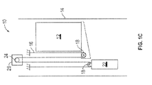
FIG. 1C is a schematic of another exemplary elevator system having a cantilevered arrangement; -
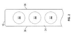
FIG. 2 is a cross-sectional view of an embodiment of an elevator belt; -
FIG. 3 is a cross-sectional view of an embodiment of a cord for an elevator belt; -
FIG. 4 is a cross-sectional view of an embodiment of a belt servicing apparatus for an elevator system; -
FIG. 5 is a cross-sectional view of another embodiment of a belt servicing apparatus for an elevator system; and -
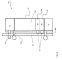
FIG. 6 is a cross-sectional view of another embodiment of a belt servicing apparatus. - The detailed description explains the invention, together with advantages and features, by way of examples with reference to the drawings.
- Shown in
FIGS. 1A ,1B and1C are schematics of exemplarytraction elevator systems 10. Features of theelevator system 10 that are not required for an understanding of the present invention (such as the guide rails, safeties, etc.) are not discussed herein. Theelevator system 10 includes anelevator car 12 operatively suspended or supported in ahoistway 14 with one ormore belts 16. The one ormore belts 16 interact with one ormore deflector sheaves 18 to be routed around various components of theelevator system 10. The one ormore belts 16 could also be connected to acounterweight 22, which is used to help balance theelevator system 10 and reduce the difference in belt tension on both sides of the traction sheave during operation. While the embodiments herein are described with reference to coated steel belts, it is to be appreciated that the disclosure herein may similarly be applied to other tension members, such as coated steel ropes for example. - The deflector sheaves 18 each have a
diameter 20, which may be the same or different than the diameters of theother deflector sheaves 18 in theelevator system 10. At least one of the sheaves could be atraction sheave 24. Thetraction sheave 24 is driven by amachine 26. Movement of thetraction sheave 24 by themachine 26 drives, moves and/or propels (through traction) the one ormore belts 16 that are routed around thetraction sheave 24. - In some embodiments, the
elevator system 10 could use two ormore belts 16 for suspending and/or driving theelevator car 12. In addition, theelevator system 10 could have various configurations such that either both sides of the one ormore belts 16 engage the one or more deflector sheaves 18 (such as shown in the exemplary elevator systems inFIGS. 1A ,1B or1C ) or only one side of the one ormore belts 16 engages the one or more sheaves 18. -
FIG 1A provides a 1:1 roping arrangement in which the one ormore belts 16 terminate at thecar 12 andcounterweight 22.FIGS. 1B and1C provide different roping arrangements. Specifically,FIGS. 1B and1C show that thecar 12 and/or thecounterweight 22 can have one or more deflector sheaves 18 thereon engaging the one ormore belts 16 and the one ormore belts 16 can terminate elsewhere, typically at a structure within the hoistway 14 (such as for a machineroomless elevator system) or within the machine room (for elevator systems utilizing a machine room). The number ofdeflector sheaves 18 used in the arrangement determines the specific roping ratio (e.g., the 2:1 roping ratio shown inFIGS. 1B and1C or a different ratio).FIG 1C also provides a cantilevered type elevator. The disclosure provided herein could be used on elevator systems other than the exemplary types shown inFIGS. 1A ,1B and1C . -
FIG. 2 provides a schematic of an example of a belt construction or design. Eachbelt 16 is constructed of a plurality of wires 28 (e.g. twisted into one ormore strands 30 and/orcords 32 as shown inFIG. 3 ) in ajacket 34. As seen inFIG. 2 , thebelt 16 has an aspect ratio greater than one (i.e. belt width is greater than belt thickness) such that thebelt 16 has a generally rectangular geometry. Thebelts 16 are constructed to have sufficient flexibility when passing over the one ormore deflector sheaves 18 to provide low bending stresses, meet belt life requirements, and have smooth operation, while being sufficiently strong to meet strength requirements for suspending and/or driving theelevator car 12 andcounterweight 22. Thewires 28 may be steel, or formed from other metals. Alternatively, the cords could be formed from fiber bundles and have various shapes and sizes. Thejacket 34 could be any suitable material, including a single material, multiple materials, two or more layers using the same or dissimilar materials, and/or a film. In one arrangement, thejacket 34 could be a polymer, such as a thermoplastic elastomer, applied to thecords 32 using, for example, an extrusion or a mold wheel process. - The
jacket 34 can substantially retain thecords 32 therein. The phrase substantially retain means that thejacket 34 has sufficient engagement with thecords 32 to transfer torque from themachine 26 through thejacket 34 to thecords 32 to drive movement of theelevator car 12. Thejacket 34 could completely envelop the cords 32 (such as shown inFIG. 2 ), substantially envelop thecords 24, or at least partially envelop thecords 32. - Over time, by operation of the
elevator system 10, thejacket 34 wears, altering a surface roughness of anouter surface 36 of thejacket 34. Altering of the geometry and surface properties affects performance of thebelt 16 and operational characteristics of theelevator system 10, such as noise, vibration and ride quality for example. To restore one or more functional characteristics of thebelt 16, such as the geometry thereof for example, abelt servicing apparatus 40, such as shown inFIGS. 4 and5 may be utilized. - The
belt servicing apparatus 40 includes at least oneguide member 41 and ahousing 42 in which one or more components of thebelt servicing apparatus 40 are positioned. Theguide members 41 are positioned on an opposing side of thebelt 16 from thehousing 42 and are configured to guide movement of at least onebelt 16 relative to thebelt servicing device 40. Disposed within a portion of thehousing 42 is one ormore reservoirs 44 containing at least one restoring material R to be applied over a worn portion of thebelt jacket 34. Embodiments where the restoring material is a liquid or a non-liquid, such as a tape for example, are both within the scope of the disclosure. The restoring material within thereservoir 44 may be selected from any flexible or ductile material capable of meeting the requirements defined by a specification of the belt, including but not limited to urethane, epoxy, and acrylic for example. In one embodiment, the restoring material may need to be cured to achieve the properties necessary for normal operation of the belt. - The restoring material may be a surface treatment configured to alter the surface chemistry or frictional characteristics to address specific noise quality issues. Examples of such surface treatments include, but are not limited to wax, surfactant or other lubricating or low surface energy materials to reduce friction and address belt noise issues for example. Alternatively, or in addition, the restoring material may be a surface treatment including adhesives, plasticizing agents or other high friction or high surface energy materials intended to address the low traction of the belts.
- In addition, in some embodiments, a plurality of restoring materials may be disposed within the at least one
reservoir 44. For example, in the non-limiting embodiment illustrated inFIG. 6 , the plurality of restoring materials include a first restoring material R1 comprising a primer and the second restoring material R2 configured to build up the thickness of a worn portion of thebelt 16. Application of the primer R1 is configured to promote adhesion between the second restoring material R2 and at least one of the existingjacket material 34 and/or thecords 32. It should be understood that the illustrated of the at least onereservoir 44 indicated in the FIGS. is intended as an example, and other locations of thereservoir 44 within thebelt servicing apparatus 40 are within the scope of the disclosure. - Mounted to the
housing 42 generally adjacent to the at least onereservoir 44 is anapplicator 46 for applying the material from thereservoir 44 to anadjacent surface 36 of thebelt 16. In some embodiments, the one ormore applicators 46 may include a blade (FIG. 4 ) or a roller (FIG. 5 ), configured to directly contact thebelt 16. Alternatively, theapplicator 46 may include a spray nozzle configured to spray a restoring material from the at least onereservoir 44 onto thebelt 16. - The
housing 42 of thebelt servicing device 40 may be configured to receive a plurality of attachments or sub-systems. For example, in embodiments where the restoring material R requires curing via application of heat or other energy, thedevice 40 may include a curingattachment 48, for example having an ultraviolet or infrared lamp. However, in other embodiments, the ultraviolet or infrared lamp may be positioned within thehousing 42. The curingattachment 48 is configured to transmit heat or other energy to a directly adjacent portion of thebelt 16. By positioning thecuring attachment 48 generally downstream from thereservoir 44 with respect to movement of thebelt 16 relative to thebelt servicing device 40, restoring material R may first be applied to a worn portion of thebelt 16 and then cured by the curingattachment 48. - Alternatively, or in addition, an
attachment 50 configured to automatically prepare the surface of thebelt 16, such as by removing debris therefrom or by application of one or more cleaning materials for example, may be connected to a portion of the housing 42 (seeFIG. 6 ). In such embodiments, thispretreatment attachment 50 is generally mounted to thehousing 42 upstream from the at least onereservoir 44 such that thebelt 16 is cleaned prior to application of the restoring material R. In embodiments of thebelt servicing device 40 that do not include thepretreatment attachment 50, cleaning or other treatment of thebelt 16 prior to application of the restoring material R may be performed manually or by another device. - With further reference to
FIG. 6 , yet anotherattachment 52 configured for use with thebelt servicing device 40 includes at least one resurfacingroller 54 rotatable about an axis. In one embodiment, theattachment 52 includes two resurfacingrollers 54 positioned on opposingsides belt 16, such that thebelt 16 is positioned there between. The resurfacingrollers 54 may be formed from a metal or other heat-conductive material, and have a non-stick rollerouter surface 48. The outer surface of therollers 54 may be configured with a surface roughness substantially identical to a selected surface roughness of thejacket 34 after refinishing. It is to be appreciated that while two resurfacing rollers are shown in the embodiment ofFIG. 6 , in other embodiments, thebelt 16 may be positioned between one resurfacingroller 42 and another surface, for example a low friction plate or other surface. Such embodiments may be utilized for resurfacing one side of thebelt 16 at a time, or in situations where resurfacing of only one side of thebelt 16 is desired. - To restore the rectangular geometry and surface properties of the
jacket 34, thebelt servicing device 40 is arranged at some position within thehoistway 14. When installed, one ormore belts 16 are positioned between theguide members 41 and thehousing 42. In one embodiment, thebelt servicing device 40 remains fixed at a location within thehoistway 14 and theelevator car 12 is driven between landings to move the at least onebelt 16 relative to thebelt servicing device 40. In another embodiment, however, thebelt servicing device 40 may be configured to move relative to asurface 36 of the one ormore belts 16. For example, the at least oneguide roller 41 may be used to drive thebelt servicing device 40 along a length of the at least onebelt 16. - The
belt restoring device 40 may be configured to restore the original geometry of thebelt 16 in a single pass. In another embodiment, however, multiple passes of thebelt restoring device 40 may be necessary to build up the restoring material to achieve the original geometry of thebelt 16. As thebelt 16 moves relative to thebelt servicing device 40, thebelt 16 passes by the at least onereservoir 44 and any of theother attachments housing 42 in a desired sequence. For example, as thebelt 16 moves relative to thebelt servicing device 40, theapplicators 46 apply a coating of restoring material to thesurface 36 of thebelt 16 to achieve a rectangular geometry substantially identical to the original geometry of thebelt 16. The restoring material R applied to thebelt 16 may then be cured, such as by the heat generated by a curingattachment 48 of thedevice 40. - In embodiments of the
belt servicing device 40 includingattachment 52 having at least one resurfacingroller 54, the resurfacingroller 54 may be heated to soften theouter surface 36 and imprint the surface roughness from the resurfacingroller 54 into theouter surface 36 of thejacket 34. In other embodiments, the heat or energy applied to thebelt 16 via the curingattachment 48 is configured to soften thebelt 16 such that the at least one resurfacingroller 54 need not be heated. In one embodiment,attachment 52 includes at least one tensioning spring such that the resurfacingroller 54 contacts thebelt 16 with a desired pressure. Once through the resurfacingroller 54, theouter surface 36 rehardens with the selected surface roughness matching that of the resurfacingroller 54. In another embodiment, the resurfacingroller 54 may be used to finalize or adjust the thickness of thebelt 16. In such instances, a fixed gap of a desired size is formed between the resurfacingrollers 54 such that thebelt 16 is sized to a desired thickness as it moves there through. - In addition, the
belt restoring device 40 may be configured to measure a thickness of thejacket 34 to determine an appropriate quantity of restoring material R to apply to a portion of thebelt 16 via the at least oneapplicator 46. Examples of devices configured to measure the thickness of thejacket 36 include a magnetic induction probe, a magnetic pin or brush, and an optical detector for example. In response to the feedback provided by the measuring device, a position of the at least oneapplicator 46 may be modified to vary the amount of restoring material applied to thebelt 16. - In some embodiments, the one or
more applicators 46 may include a printer or a fused deposition device. The restoring material may be added to thebelt 16 by printing or fused deposition. An example material to be applied by printing or fused deposition includes thermoplastic polyurethane (TPU). - The
belt servicing device 40 disclosed herein allows field repair of aworn belt 16 to restore the original geometry and improve traction and other operational characteristics of thebelt 16 and theelevator system 10. The device and method does not require unroping of thebelt 16 from its installed position in thehoistway 14 for resurfacing and thus saves time and labor. Further, the device and method allows for service of a worn belt, thus avoiding premature replacement of the belt. - While the invention has been described in detail in connection with only a limited number of embodiments, it should be readily understood that the invention is not limited to such disclosed embodiments. Rather, the invention can be modified to incorporate any number of variations, alterations, substitutions or equivalent arrangements not heretofore described, but which are commensurate with the scope of the invention. Additionally, while various embodiments of the invention have been described, it is to be understood that aspects of the invention may include only some of the described embodiments. Accordingly, the invention is not to be seen as limited by the foregoing description, but is only limited by the scope of the appended claims.
Claims (15)
- A servicing device (40) configured for use with a belt (16) of an elevator system having an original geometry, the servicing device comprising:a housing (42);a guide member (41) coupled to the housing (42);at least one reservoir (44) disposed within the housing (42), the at least one reservoir (44) containing one or more restoring materials (R); andan applicator (46) configured to apply the one or more restoring materials (R) to an adjacent surface of the belt (16), wherein application of the one or more restoring materials is configured to modify a geometry of the belt (16) such that the modified geometry is substantially identical to an original geometry of the belt (16).
- The servicing device of claim 1, wherein the servicing device (40) is fixed at a hoistway of the elevator system and the belt (16) is configured to move relative to the servicing device, (40) or wherein the servicing device (40) is connected to the belt (16) and is configured to move relative to the belt (16).
- The servicing device of claim 1 or 2, wherein the one or more restoring materials includes a first restoring material (R1) and a second restoring material (R2), the first restoring material (R1) being configured to promote adhesion between an existing material of the belt (16) and the second restoring material (R2).
- The servicing device of any preceding claim, further comprising a curing attachment (48) configured to cure the restoring material.
- The servicing device of claim 4, wherein the curing attachment (48) is positioned generally downstream from the at least one reservoir (44) with respect to a direction of movement of at least one of the belt (16) and the servicing device (40).
- The servicing device of any preceding claim, further comprising a pretreatment attachment (50) configured to prepare a surface of the belt (16), the pretreatment attachment (50) being mounted to the housing generally upstream from the reservoir (44) with respect to a direction of movement of at least one of the belt (16) and the servicing device (40).
- The servicing device of any preceding claim, further comprising an attachment (54) including at least one resurfacing roller configured to apply a selected pressure to the belt (16) to modify a surface finish of an outer surface of the belt.
- The servicing device of any preceding claim, further comprising a mechanism for measuring a thickness of the belt (16).
- The servicing device of any preceding claim, wherein the restoring material (R) is a surface treatment configured to alter at least one of friction, noise, and traction of the belt (16).
- The servicing device of any preceding claim, wherein the one or more restoring materials (R) is applied by printing or fused deposition.
- An elevator system comprising:an elevator car (12);a motor (26);a traction sheave (24) operably connected to the motor drive rotation of the traction sheave (24);at least one belt (16) operably connected to the elevator car, the at least one belt having an original geometry and being arranged in frictional contact with the traction sheave (24) such that rotation of the traction sheave urges movement of the elevator car (12); anda servicing device as claimed in any preceding claim for the at least one belt.
- A method for altering a geometry of a belt (16) of an elevator system comprising:positioning a servicing device (40) adjacent an outer surface of the belt (16);moving at least one of the servicing device (40) and the belt (16);applying at least one restoring material (R) to an existing material of the belt (16); andcuring the at least one restoring material (R) such that a geometry of the belt (16) is substantially identical to an original geometry of the belt (16).
- The method according to claim 12, further comprising pretreating a surface of the belt (16) prior to applying the at least one restoring material (R).
- The method according to claim 12 or 13, further comprising altering a surface roughness of the belt (16) via application of a resurfacing roller (54) to the belt (16) at a selected pressure.
- The method according to claim 12, 13 or 14, further comprising:measuring a thickness of the belt (16);determining a quantity of restoring material (R) necessary to achieve the original geometry of the belt (16); andadjusting a position of at least one applicator (46)configured to apply the restoring material (R) to the belt (16).
Applications Claiming Priority (1)
| Application Number | Priority Date | Filing Date | Title |
|---|---|---|---|
| US201562218191P | 2015-09-14 | 2015-09-14 |
Publications (2)
| Publication Number | Publication Date |
|---|---|
| EP3141514A1 true EP3141514A1 (en) | 2017-03-15 |
| EP3141514B1 EP3141514B1 (en) | 2019-07-03 |
Family
ID=56979367
Family Applications (1)
| Application Number | Title | Priority Date | Filing Date |
|---|---|---|---|
| EP16188708.8A Active EP3141514B1 (en) | 2015-09-14 | 2016-09-14 | In-service repair of elevator belt |
Country Status (4)
| Country | Link |
|---|---|
| US (1) | US10280044B2 (en) |
| EP (1) | EP3141514B1 (en) |
| CN (1) | CN106516937B (en) |
| ES (1) | ES2741353T3 (en) |
Families Citing this family (3)
| Publication number | Priority date | Publication date | Assignee | Title |
|---|---|---|---|---|
| WO2015076827A1 (en) * | 2013-11-22 | 2015-05-28 | Otis Elevator Company | Resurfacing of belt for elevator system |
| US10974929B2 (en) * | 2016-11-07 | 2021-04-13 | Otis Elevator Company | Load bearing member for an elevator system having an elastomer and phosphonate blended bonding agent |
| CN113071118B (en) * | 2021-04-30 | 2023-04-14 | 辽宁工程技术大学 | A Vibrating Plate Coordinated Conveyor Belt Wear Repair Device and Using Method |
Citations (3)
| Publication number | Priority date | Publication date | Assignee | Title |
|---|---|---|---|---|
| JPH08133650A (en) * | 1994-11-14 | 1996-05-28 | Hitachi Building Syst Eng & Service Co Ltd | Coating method for man conveyor handrail |
| CN201872353U (en) * | 2010-10-15 | 2011-06-22 | 山东晨光胶带有限公司 | Rubber belt repairing device |
| WO2015076827A1 (en) * | 2013-11-22 | 2015-05-28 | Otis Elevator Company | Resurfacing of belt for elevator system |
Family Cites Families (10)
| Publication number | Priority date | Publication date | Assignee | Title |
|---|---|---|---|---|
| US4224601A (en) * | 1978-03-27 | 1980-09-23 | Davidson Sam A | Electrodynamic printing system |
| US4211743A (en) * | 1978-05-24 | 1980-07-08 | Nauta Roll Corporation | Apparatus and method for embossing web material |
| DE19543316A1 (en) * | 1995-11-21 | 1997-05-22 | Bielomatik Leuze & Co | Processing tool for processing layer material or the like |
| DE102004030722A1 (en) * | 2004-06-25 | 2006-01-19 | Contitech Antriebssysteme Gmbh | Flat belts for elevator systems provided with reinforcements |
| US20070014886A1 (en) * | 2005-02-02 | 2007-01-18 | Michael Hennessey | Method and apparatus for forming microstructures on polymeric substrates |
| WO2006085881A1 (en) * | 2005-02-09 | 2006-08-17 | Otis Elevator Company | Elevator load bearing member having a jacket with at least one traction-enhancing exterior surface |
| ES2402930T5 (en) * | 2005-09-13 | 2016-12-05 | Otis Elevator Company | Method of manufacturing a load bearing element for an elevator system |
| WO2008110241A2 (en) * | 2007-03-12 | 2008-09-18 | Inventio Ag | Elevator system, carrying means for an elevator system, and method for the production of a carrying means |
| US8120205B2 (en) * | 2008-07-18 | 2012-02-21 | Zilker Labs, Inc. | Adding and dropping phases in current sharing |
| EP2323835A4 (en) * | 2008-08-18 | 2014-06-04 | Macro Engineering & Technology Inc | Heat treatment of thin polymer films |
-
2016
- 2016-09-14 EP EP16188708.8A patent/EP3141514B1/en active Active
- 2016-09-14 CN CN201610825930.XA patent/CN106516937B/en active Active
- 2016-09-14 ES ES16188708T patent/ES2741353T3/en active Active
- 2016-09-14 US US15/264,791 patent/US10280044B2/en active Active
Patent Citations (3)
| Publication number | Priority date | Publication date | Assignee | Title |
|---|---|---|---|---|
| JPH08133650A (en) * | 1994-11-14 | 1996-05-28 | Hitachi Building Syst Eng & Service Co Ltd | Coating method for man conveyor handrail |
| CN201872353U (en) * | 2010-10-15 | 2011-06-22 | 山东晨光胶带有限公司 | Rubber belt repairing device |
| WO2015076827A1 (en) * | 2013-11-22 | 2015-05-28 | Otis Elevator Company | Resurfacing of belt for elevator system |
Non-Patent Citations (1)
| Title |
|---|
| DATABASE WPI Week 201158, Derwent World Patents Index; AN 2011-J47111, XP002765842 * |
Also Published As
| Publication number | Publication date |
|---|---|
| US10280044B2 (en) | 2019-05-07 |
| EP3141514B1 (en) | 2019-07-03 |
| CN106516937A (en) | 2017-03-22 |
| CN106516937B (en) | 2020-05-19 |
| ES2741353T3 (en) | 2020-02-10 |
| US20170073195A1 (en) | 2017-03-16 |
Similar Documents
| Publication | Publication Date | Title |
|---|---|---|
| EP3141514B1 (en) | In-service repair of elevator belt | |
| KR102558412B1 (en) | Elevator belt with additive layer | |
| EP3071504B1 (en) | Idler or deflector sheave for elevator system | |
| RU2600423C2 (en) | Elevator braking system and method of elevator braking | |
| CN101495397B (en) | Drive machine of movable pedestrian, drive belt replacing method and support member | |
| JP5098958B2 (en) | Man conveyor moving handrail device, man conveyor handrail and manufacturing method thereof | |
| CN108217384B (en) | Elevator system suspension member termination with restraint | |
| CN1902358A (en) | flexible traction member | |
| AU2017268631A1 (en) | Overbraided non-metallic tension members | |
| US9994423B2 (en) | Resurfacing of belt for elevator system | |
| EP2969876B1 (en) | Traction sheave for elevator system | |
| JP2018062393A (en) | Elevator rope cleaning device | |
| KR102520029B1 (en) | Termination for elevator belt | |
| KR102468203B1 (en) | Belt sheave and method of imprinting | |
| US9701517B2 (en) | Methods and apparatuses for applying a substrate onto an elevator sheave | |
| JP2016145096A (en) | Slip agent coating device for escalator and escalator | |
| JP6235074B1 (en) | Passenger conveyor handrail belt and passenger conveyor using the same | |
| CN120055977A (en) | Aluminum profile surface treatment device and method | |
| HK1133631B (en) | A drive machinery of a travelator, method for replacing the drive belt and support element | |
| JP2016160016A (en) | Guide device, man conveyor, and repair method for man conveyor | |
| JP2016150827A (en) | Passenger conveyor oil supply device |
Legal Events
| Date | Code | Title | Description |
|---|---|---|---|
| PUAI | Public reference made under article 153(3) epc to a published international application that has entered the european phase |
Free format text: ORIGINAL CODE: 0009012 |
|
| STAA | Information on the status of an ep patent application or granted ep patent |
Free format text: STATUS: THE APPLICATION HAS BEEN PUBLISHED |
|
| AK | Designated contracting states |
Kind code of ref document: A1 Designated state(s): AL AT BE BG CH CY CZ DE DK EE ES FI FR GB GR HR HU IE IS IT LI LT LU LV MC MK MT NL NO PL PT RO RS SE SI SK SM TR |
|
| AX | Request for extension of the european patent |
Extension state: BA ME |
|
| RAP1 | Party data changed (applicant data changed or rights of an application transferred) |
Owner name: OTIS ELEVATOR COMPANY |
|
| STAA | Information on the status of an ep patent application or granted ep patent |
Free format text: STATUS: REQUEST FOR EXAMINATION WAS MADE |
|
| 17P | Request for examination filed |
Effective date: 20170915 |
|
| RBV | Designated contracting states (corrected) |
Designated state(s): AL AT BE BG CH CY CZ DE DK EE ES FI FR GB GR HR HU IE IS IT LI LT LU LV MC MK MT NL NO PL PT RO RS SE SI SK SM TR |
|
| GRAP | Despatch of communication of intention to grant a patent |
Free format text: ORIGINAL CODE: EPIDOSNIGR1 |
|
| STAA | Information on the status of an ep patent application or granted ep patent |
Free format text: STATUS: GRANT OF PATENT IS INTENDED |
|
| INTG | Intention to grant announced |
Effective date: 20180628 |
|
| GRAJ | Information related to disapproval of communication of intention to grant by the applicant or resumption of examination proceedings by the epo deleted |
Free format text: ORIGINAL CODE: EPIDOSDIGR1 |
|
| STAA | Information on the status of an ep patent application or granted ep patent |
Free format text: STATUS: REQUEST FOR EXAMINATION WAS MADE |
|
| INTC | Intention to grant announced (deleted) | ||
| GRAP | Despatch of communication of intention to grant a patent |
Free format text: ORIGINAL CODE: EPIDOSNIGR1 |
|
| STAA | Information on the status of an ep patent application or granted ep patent |
Free format text: STATUS: GRANT OF PATENT IS INTENDED |
|
| INTG | Intention to grant announced |
Effective date: 20190114 |
|
| GRAS | Grant fee paid |
Free format text: ORIGINAL CODE: EPIDOSNIGR3 |
|
| GRAA | (expected) grant |
Free format text: ORIGINAL CODE: 0009210 |
|
| STAA | Information on the status of an ep patent application or granted ep patent |
Free format text: STATUS: THE PATENT HAS BEEN GRANTED |
|
| AK | Designated contracting states |
Kind code of ref document: B1 Designated state(s): AL AT BE BG CH CY CZ DE DK EE ES FI FR GB GR HR HU IE IS IT LI LT LU LV MC MK MT NL NO PL PT RO RS SE SI SK SM TR |
|
| REG | Reference to a national code |
Ref country code: GB Ref legal event code: FG4D |
|
| REG | Reference to a national code |
Ref country code: CH Ref legal event code: EP Ref country code: AT Ref legal event code: REF Ref document number: 1150756 Country of ref document: AT Kind code of ref document: T Effective date: 20190715 |
|
| REG | Reference to a national code |
Ref country code: IE Ref legal event code: FG4D |
|
| REG | Reference to a national code |
Ref country code: DE Ref legal event code: R096 Ref document number: 602016016188 Country of ref document: DE |
|
| REG | Reference to a national code |
Ref country code: NL Ref legal event code: MP Effective date: 20190703 |
|
| REG | Reference to a national code |
Ref country code: LT Ref legal event code: MG4D |
|
| REG | Reference to a national code |
Ref country code: AT Ref legal event code: MK05 Ref document number: 1150756 Country of ref document: AT Kind code of ref document: T Effective date: 20190703 |
|
| PG25 | Lapsed in a contracting state [announced via postgrant information from national office to epo] |
Ref country code: FI Free format text: LAPSE BECAUSE OF FAILURE TO SUBMIT A TRANSLATION OF THE DESCRIPTION OR TO PAY THE FEE WITHIN THE PRESCRIBED TIME-LIMIT Effective date: 20190703 Ref country code: CZ Free format text: LAPSE BECAUSE OF FAILURE TO SUBMIT A TRANSLATION OF THE DESCRIPTION OR TO PAY THE FEE WITHIN THE PRESCRIBED TIME-LIMIT Effective date: 20190703 Ref country code: HR Free format text: LAPSE BECAUSE OF FAILURE TO SUBMIT A TRANSLATION OF THE DESCRIPTION OR TO PAY THE FEE WITHIN THE PRESCRIBED TIME-LIMIT Effective date: 20190703 Ref country code: NL Free format text: LAPSE BECAUSE OF FAILURE TO SUBMIT A TRANSLATION OF THE DESCRIPTION OR TO PAY THE FEE WITHIN THE PRESCRIBED TIME-LIMIT Effective date: 20190703 Ref country code: BG Free format text: LAPSE BECAUSE OF FAILURE TO SUBMIT A TRANSLATION OF THE DESCRIPTION OR TO PAY THE FEE WITHIN THE PRESCRIBED TIME-LIMIT Effective date: 20191003 Ref country code: SE Free format text: LAPSE BECAUSE OF FAILURE TO SUBMIT A TRANSLATION OF THE DESCRIPTION OR TO PAY THE FEE WITHIN THE PRESCRIBED TIME-LIMIT Effective date: 20190703 Ref country code: LT Free format text: LAPSE BECAUSE OF FAILURE TO SUBMIT A TRANSLATION OF THE DESCRIPTION OR TO PAY THE FEE WITHIN THE PRESCRIBED TIME-LIMIT Effective date: 20190703 Ref country code: PT Free format text: LAPSE BECAUSE OF FAILURE TO SUBMIT A TRANSLATION OF THE DESCRIPTION OR TO PAY THE FEE WITHIN THE PRESCRIBED TIME-LIMIT Effective date: 20191104 Ref country code: NO Free format text: LAPSE BECAUSE OF FAILURE TO SUBMIT A TRANSLATION OF THE DESCRIPTION OR TO PAY THE FEE WITHIN THE PRESCRIBED TIME-LIMIT Effective date: 20191003 Ref country code: AT Free format text: LAPSE BECAUSE OF FAILURE TO SUBMIT A TRANSLATION OF THE DESCRIPTION OR TO PAY THE FEE WITHIN THE PRESCRIBED TIME-LIMIT Effective date: 20190703 |
|
| REG | Reference to a national code |
Ref country code: ES Ref legal event code: FG2A Ref document number: 2741353 Country of ref document: ES Kind code of ref document: T3 Effective date: 20200210 |
|
| PG25 | Lapsed in a contracting state [announced via postgrant information from national office to epo] |
Ref country code: LV Free format text: LAPSE BECAUSE OF FAILURE TO SUBMIT A TRANSLATION OF THE DESCRIPTION OR TO PAY THE FEE WITHIN THE PRESCRIBED TIME-LIMIT Effective date: 20190703 Ref country code: IS Free format text: LAPSE BECAUSE OF FAILURE TO SUBMIT A TRANSLATION OF THE DESCRIPTION OR TO PAY THE FEE WITHIN THE PRESCRIBED TIME-LIMIT Effective date: 20191103 Ref country code: AL Free format text: LAPSE BECAUSE OF FAILURE TO SUBMIT A TRANSLATION OF THE DESCRIPTION OR TO PAY THE FEE WITHIN THE PRESCRIBED TIME-LIMIT Effective date: 20190703 Ref country code: RS Free format text: LAPSE BECAUSE OF FAILURE TO SUBMIT A TRANSLATION OF THE DESCRIPTION OR TO PAY THE FEE WITHIN THE PRESCRIBED TIME-LIMIT Effective date: 20190703 Ref country code: GR Free format text: LAPSE BECAUSE OF FAILURE TO SUBMIT A TRANSLATION OF THE DESCRIPTION OR TO PAY THE FEE WITHIN THE PRESCRIBED TIME-LIMIT Effective date: 20191004 |
|
| PG25 | Lapsed in a contracting state [announced via postgrant information from national office to epo] |
Ref country code: TR Free format text: LAPSE BECAUSE OF FAILURE TO SUBMIT A TRANSLATION OF THE DESCRIPTION OR TO PAY THE FEE WITHIN THE PRESCRIBED TIME-LIMIT Effective date: 20190703 |
|
| PG25 | Lapsed in a contracting state [announced via postgrant information from national office to epo] |
Ref country code: PL Free format text: LAPSE BECAUSE OF FAILURE TO SUBMIT A TRANSLATION OF THE DESCRIPTION OR TO PAY THE FEE WITHIN THE PRESCRIBED TIME-LIMIT Effective date: 20190703 Ref country code: IT Free format text: LAPSE BECAUSE OF FAILURE TO SUBMIT A TRANSLATION OF THE DESCRIPTION OR TO PAY THE FEE WITHIN THE PRESCRIBED TIME-LIMIT Effective date: 20190703 Ref country code: EE Free format text: LAPSE BECAUSE OF FAILURE TO SUBMIT A TRANSLATION OF THE DESCRIPTION OR TO PAY THE FEE WITHIN THE PRESCRIBED TIME-LIMIT Effective date: 20190703 Ref country code: RO Free format text: LAPSE BECAUSE OF FAILURE TO SUBMIT A TRANSLATION OF THE DESCRIPTION OR TO PAY THE FEE WITHIN THE PRESCRIBED TIME-LIMIT Effective date: 20190703 Ref country code: DK Free format text: LAPSE BECAUSE OF FAILURE TO SUBMIT A TRANSLATION OF THE DESCRIPTION OR TO PAY THE FEE WITHIN THE PRESCRIBED TIME-LIMIT Effective date: 20190703 |
|
| PG25 | Lapsed in a contracting state [announced via postgrant information from national office to epo] |
Ref country code: SK Free format text: LAPSE BECAUSE OF FAILURE TO SUBMIT A TRANSLATION OF THE DESCRIPTION OR TO PAY THE FEE WITHIN THE PRESCRIBED TIME-LIMIT Effective date: 20190703 Ref country code: IS Free format text: LAPSE BECAUSE OF FAILURE TO SUBMIT A TRANSLATION OF THE DESCRIPTION OR TO PAY THE FEE WITHIN THE PRESCRIBED TIME-LIMIT Effective date: 20200224 Ref country code: SM Free format text: LAPSE BECAUSE OF FAILURE TO SUBMIT A TRANSLATION OF THE DESCRIPTION OR TO PAY THE FEE WITHIN THE PRESCRIBED TIME-LIMIT Effective date: 20190703 Ref country code: MC Free format text: LAPSE BECAUSE OF FAILURE TO SUBMIT A TRANSLATION OF THE DESCRIPTION OR TO PAY THE FEE WITHIN THE PRESCRIBED TIME-LIMIT Effective date: 20190703 |
|
| REG | Reference to a national code |
Ref country code: CH Ref legal event code: PL |
|
| REG | Reference to a national code |
Ref country code: DE Ref legal event code: R097 Ref document number: 602016016188 Country of ref document: DE |
|
| PLBE | No opposition filed within time limit |
Free format text: ORIGINAL CODE: 0009261 |
|
| STAA | Information on the status of an ep patent application or granted ep patent |
Free format text: STATUS: NO OPPOSITION FILED WITHIN TIME LIMIT |
|
| PG2D | Information on lapse in contracting state deleted |
Ref country code: IS |
|
| PG25 | Lapsed in a contracting state [announced via postgrant information from national office to epo] |
Ref country code: IE Free format text: LAPSE BECAUSE OF NON-PAYMENT OF DUE FEES Effective date: 20190914 Ref country code: CH Free format text: LAPSE BECAUSE OF NON-PAYMENT OF DUE FEES Effective date: 20190930 Ref country code: LU Free format text: LAPSE BECAUSE OF NON-PAYMENT OF DUE FEES Effective date: 20190914 Ref country code: LI Free format text: LAPSE BECAUSE OF NON-PAYMENT OF DUE FEES Effective date: 20190930 |
|
| REG | Reference to a national code |
Ref country code: BE Ref legal event code: MM Effective date: 20190930 |
|
| 26N | No opposition filed |
Effective date: 20200603 |
|
| PG25 | Lapsed in a contracting state [announced via postgrant information from national office to epo] |
Ref country code: SI Free format text: LAPSE BECAUSE OF FAILURE TO SUBMIT A TRANSLATION OF THE DESCRIPTION OR TO PAY THE FEE WITHIN THE PRESCRIBED TIME-LIMIT Effective date: 20190703 Ref country code: BE Free format text: LAPSE BECAUSE OF NON-PAYMENT OF DUE FEES Effective date: 20190930 |
|
| GBPC | Gb: european patent ceased through non-payment of renewal fee |
Effective date: 20200914 |
|
| PG25 | Lapsed in a contracting state [announced via postgrant information from national office to epo] |
Ref country code: CY Free format text: LAPSE BECAUSE OF FAILURE TO SUBMIT A TRANSLATION OF THE DESCRIPTION OR TO PAY THE FEE WITHIN THE PRESCRIBED TIME-LIMIT Effective date: 20190703 |
|
| PG25 | Lapsed in a contracting state [announced via postgrant information from national office to epo] |
Ref country code: MT Free format text: LAPSE BECAUSE OF FAILURE TO SUBMIT A TRANSLATION OF THE DESCRIPTION OR TO PAY THE FEE WITHIN THE PRESCRIBED TIME-LIMIT Effective date: 20190703 Ref country code: HU Free format text: LAPSE BECAUSE OF FAILURE TO SUBMIT A TRANSLATION OF THE DESCRIPTION OR TO PAY THE FEE WITHIN THE PRESCRIBED TIME-LIMIT; INVALID AB INITIO Effective date: 20160914 |
|
| PG25 | Lapsed in a contracting state [announced via postgrant information from national office to epo] |
Ref country code: GB Free format text: LAPSE BECAUSE OF NON-PAYMENT OF DUE FEES Effective date: 20200914 |
|
| PG25 | Lapsed in a contracting state [announced via postgrant information from national office to epo] |
Ref country code: MK Free format text: LAPSE BECAUSE OF FAILURE TO SUBMIT A TRANSLATION OF THE DESCRIPTION OR TO PAY THE FEE WITHIN THE PRESCRIBED TIME-LIMIT Effective date: 20190703 |
|
| PGFP | Annual fee paid to national office [announced via postgrant information from national office to epo] |
Ref country code: DE Payment date: 20250820 Year of fee payment: 10 |
|
| PGFP | Annual fee paid to national office [announced via postgrant information from national office to epo] |
Ref country code: FR Payment date: 20250820 Year of fee payment: 10 |
|
| PGFP | Annual fee paid to national office [announced via postgrant information from national office to epo] |
Ref country code: ES Payment date: 20251001 Year of fee payment: 10 |