EP3141484A1 - Pipe installation - Google Patents
Pipe installation Download PDFInfo
- Publication number
- EP3141484A1 EP3141484A1 EP16185573.9A EP16185573A EP3141484A1 EP 3141484 A1 EP3141484 A1 EP 3141484A1 EP 16185573 A EP16185573 A EP 16185573A EP 3141484 A1 EP3141484 A1 EP 3141484A1
- Authority
- EP
- European Patent Office
- Prior art keywords
- fitting
- pipe
- fuel tank
- flange
- pipe installation
- Prior art date
- Legal status (The legal status is an assumption and is not a legal conclusion. Google has not performed a legal analysis and makes no representation as to the accuracy of the status listed.)
- Granted
Links
Images



Classifications
-
- B—PERFORMING OPERATIONS; TRANSPORTING
- B64—AIRCRAFT; AVIATION; COSMONAUTICS
- B64C—AEROPLANES; HELICOPTERS
- B64C3/00—Wings
- B64C3/34—Tanks constructed integrally with wings, e.g. for fuel or water
-
- B—PERFORMING OPERATIONS; TRANSPORTING
- B64—AIRCRAFT; AVIATION; COSMONAUTICS
- B64D—EQUIPMENT FOR FITTING IN OR TO AIRCRAFT; FLIGHT SUITS; PARACHUTES; ARRANGEMENT OR MOUNTING OF POWER PLANTS OR PROPULSION TRANSMISSIONS IN AIRCRAFT
- B64D37/00—Arrangements in connection with fuel supply for power plant
- B64D37/32—Safety measures not otherwise provided for, e.g. preventing explosive conditions
-
- B—PERFORMING OPERATIONS; TRANSPORTING
- B60—VEHICLES IN GENERAL
- B60K—ARRANGEMENT OR MOUNTING OF PROPULSION UNITS OR OF TRANSMISSIONS IN VEHICLES; ARRANGEMENT OR MOUNTING OF PLURAL DIVERSE PRIME-MOVERS IN VEHICLES; AUXILIARY DRIVES FOR VEHICLES; INSTRUMENTATION OR DASHBOARDS FOR VEHICLES; ARRANGEMENTS IN CONNECTION WITH COOLING, AIR INTAKE, GAS EXHAUST OR FUEL SUPPLY OF PROPULSION UNITS IN VEHICLES
- B60K15/00—Arrangement in connection with fuel supply of combustion engines or other fuel consuming energy converters, e.g. fuel cells; Mounting or construction of fuel tanks
- B60K15/03—Fuel tanks
-
- B—PERFORMING OPERATIONS; TRANSPORTING
- B64—AIRCRAFT; AVIATION; COSMONAUTICS
- B64D—EQUIPMENT FOR FITTING IN OR TO AIRCRAFT; FLIGHT SUITS; PARACHUTES; ARRANGEMENT OR MOUNTING OF POWER PLANTS OR PROPULSION TRANSMISSIONS IN AIRCRAFT
- B64D37/00—Arrangements in connection with fuel supply for power plant
- B64D37/005—Accessories not provided for in the groups B64D37/02 - B64D37/28
-
- B—PERFORMING OPERATIONS; TRANSPORTING
- B64—AIRCRAFT; AVIATION; COSMONAUTICS
- B64D—EQUIPMENT FOR FITTING IN OR TO AIRCRAFT; FLIGHT SUITS; PARACHUTES; ARRANGEMENT OR MOUNTING OF POWER PLANTS OR PROPULSION TRANSMISSIONS IN AIRCRAFT
- B64D37/00—Arrangements in connection with fuel supply for power plant
- B64D37/02—Tanks
- B64D37/04—Arrangement thereof in or on aircraft
-
- B—PERFORMING OPERATIONS; TRANSPORTING
- B64—AIRCRAFT; AVIATION; COSMONAUTICS
- B64D—EQUIPMENT FOR FITTING IN OR TO AIRCRAFT; FLIGHT SUITS; PARACHUTES; ARRANGEMENT OR MOUNTING OF POWER PLANTS OR PROPULSION TRANSMISSIONS IN AIRCRAFT
- B64D37/00—Arrangements in connection with fuel supply for power plant
- B64D37/02—Tanks
- B64D37/06—Constructional adaptations thereof
-
- B—PERFORMING OPERATIONS; TRANSPORTING
- B64—AIRCRAFT; AVIATION; COSMONAUTICS
- B64D—EQUIPMENT FOR FITTING IN OR TO AIRCRAFT; FLIGHT SUITS; PARACHUTES; ARRANGEMENT OR MOUNTING OF POWER PLANTS OR PROPULSION TRANSMISSIONS IN AIRCRAFT
- B64D45/00—Aircraft indicators or protectors not otherwise provided for
- B64D45/02—Lightning protectors; Static dischargers
-
- F—MECHANICAL ENGINEERING; LIGHTING; HEATING; WEAPONS; BLASTING
- F16—ENGINEERING ELEMENTS AND UNITS; GENERAL MEASURES FOR PRODUCING AND MAINTAINING EFFECTIVE FUNCTIONING OF MACHINES OR INSTALLATIONS; THERMAL INSULATION IN GENERAL
- F16L—PIPES; JOINTS OR FITTINGS FOR PIPES; SUPPORTS FOR PIPES, CABLES OR PROTECTIVE TUBING; MEANS FOR THERMAL INSULATION IN GENERAL
- F16L21/00—Joints with sleeve or socket
- F16L21/02—Joints with sleeve or socket with elastic sealing rings between pipe and sleeve or between pipe and socket, e.g. with rolling or other prefabricated profiled rings
-
- F—MECHANICAL ENGINEERING; LIGHTING; HEATING; WEAPONS; BLASTING
- F16—ENGINEERING ELEMENTS AND UNITS; GENERAL MEASURES FOR PRODUCING AND MAINTAINING EFFECTIVE FUNCTIONING OF MACHINES OR INSTALLATIONS; THERMAL INSULATION IN GENERAL
- F16L—PIPES; JOINTS OR FITTINGS FOR PIPES; SUPPORTS FOR PIPES, CABLES OR PROTECTIVE TUBING; MEANS FOR THERMAL INSULATION IN GENERAL
- F16L25/00—Construction or details of pipe joints not provided for in, or of interest apart from, groups F16L13/00 - F16L23/00
- F16L25/01—Construction or details of pipe joints not provided for in, or of interest apart from, groups F16L13/00 - F16L23/00 specially adapted for realising electrical conduction between the two pipe ends of the joint or between parts thereof
-
- F—MECHANICAL ENGINEERING; LIGHTING; HEATING; WEAPONS; BLASTING
- F16—ENGINEERING ELEMENTS AND UNITS; GENERAL MEASURES FOR PRODUCING AND MAINTAINING EFFECTIVE FUNCTIONING OF MACHINES OR INSTALLATIONS; THERMAL INSULATION IN GENERAL
- F16L—PIPES; JOINTS OR FITTINGS FOR PIPES; SUPPORTS FOR PIPES, CABLES OR PROTECTIVE TUBING; MEANS FOR THERMAL INSULATION IN GENERAL
- F16L25/00—Construction or details of pipe joints not provided for in, or of interest apart from, groups F16L13/00 - F16L23/00
- F16L25/02—Construction or details of pipe joints not provided for in, or of interest apart from, groups F16L13/00 - F16L23/00 specially adapted for electrically insulating the two pipe ends of the joint from each other
-
- B—PERFORMING OPERATIONS; TRANSPORTING
- B60—VEHICLES IN GENERAL
- B60K—ARRANGEMENT OR MOUNTING OF PROPULSION UNITS OR OF TRANSMISSIONS IN VEHICLES; ARRANGEMENT OR MOUNTING OF PLURAL DIVERSE PRIME-MOVERS IN VEHICLES; AUXILIARY DRIVES FOR VEHICLES; INSTRUMENTATION OR DASHBOARDS FOR VEHICLES; ARRANGEMENTS IN CONNECTION WITH COOLING, AIR INTAKE, GAS EXHAUST OR FUEL SUPPLY OF PROPULSION UNITS IN VEHICLES
- B60K15/00—Arrangement in connection with fuel supply of combustion engines or other fuel consuming energy converters, e.g. fuel cells; Mounting or construction of fuel tanks
- B60K15/03—Fuel tanks
- B60K2015/03328—Arrangements or special measures related to fuel tanks or fuel handling
- B60K2015/03401—Arrangements or special measures related to fuel tanks or fuel handling for preventing electrostatic charges
Definitions
- the present invention relates to a pipe installation, typically although not exclusively in an aircraft fuel tank.
- US2012/0012709 describes a known supporting structure between a fuel pipe and a rib within an aircraft fuel tank.
- the supporting structure is provided with an insulating section which electrically insulates the pipe and the rib. This prevents a spark discharge between the pipe and the rib.
- a first aspect of the present invention provides a pipe installation comprising: conductive first and second pipes installed in a fuel tank; and a fitting which connects the first and second pipes and enables fluid to flow through the pipes via a conduit in the fitting, wherein the fitting is attached to the first or second pipe by a flexible joint which permits relative movement between the fitting and the first or second pipe, the fitting is attached to a structure of the fuel tank, the fitting provides a path of least electrical resistance between the first or second pipe and the structure, and the path of least electrical resistance has a resistance between 50 ⁇ and 100M ⁇ .
- the fitting may be attached to the structure of the fuel tank to enable load to be transferred between the pipes and the structure via the fitting, or simply to maintain the fitting in a fixed position relative to the structure of the fuel tank.
- the minimum electrical resistance of the fitting (50 ⁇ ) limits the flow of undesirable currents such as those induced by lightning-strike or ground loops.
- the maximum electrical resistance of the fitting (100M ⁇ ) enables desirable currents to flow, for instance to dissipate electrostatic charge. This can be contrasted with US2012/0012709 in which the very high resistance of the insulating section prevents the flow of such desirable currents.
- the flexible joint enables relative movement between the fitting and the first or second pipe, enabling the installation to accommodate deformations of the fuel tank - for instance caused by thermal expansion or bending or twisting of the fuel tank.
- This can be contrasted with US2012/0012709 in which a single pipe passes through the rib, and the pipe is rigidly gripped by a clamp so that no relative movement is permitted.
- conductive pipes with low resistivity rather than pipes made from a high-resistivity material such as a polymer, enables the pipes to be manufactured easily and cheaply, for instance by extrusion.
- the fitting provides a first path of least electrical resistance between the first pipe and the structure and the first path of least electrical resistance has a resistance between 50 ⁇ and 100M ⁇ , and the fitting also provides a second path of least electrical resistance between the second pipe and the structure and the second path of least electrical resistance has a resistance between 50 ⁇ and 100M ⁇ .
- the fitting comprises a body containing the conduit, and a flange extending from the body, wherein the fitting is attached to the structure of the fuel tank by the flange.
- the flange extends radially from the body.
- the body and the flange are formed from a polymer (typically a thermoplastic polymer) mixed with conductive filler particles, and in another embodiment they are metallic.
- the body of the fitting passes through a hole in the structure of the fuel tank.
- an electrically insulating material is provided in the hole between the body of the fitting and the structure of the fuel tank.
- the electrically insulating material may be for example a coating on the fitting or the structure, or a gasket.
- the fitting further comprises a resistive element (for instance a pad such as an annular gasket) between the flange and the structure, a portion of the path of least electrical resistance passes between the flange and the structure through the resistive element, and the portion of the path of least electrical resistance has a resistance between 50 ⁇ and 100M ⁇ .
- a resistive element for instance a pad such as an annular gasket
- the body and the flange are preferably metallic.
- the resistive element may extend around only part of a circumference of the body, but more preferably it extends fully around a circumference of the body.
- the body and the flange are formed from a material with a tailored resistivity - such as a polymer mixed with conductive filler particles - and the flange is in direct contact with the structure. In this case the resistivity of the material forming the body and flange is tailored so that the path of least electrical resistance through the body and the flange has a resistance between 50 ⁇ and 100M ⁇ .
- the flange may be bonded to the structure with an adhesive with a tailored resistivity giving the desired resistance between 50 ⁇ and 100M ⁇ .
- the flange is attached to the structure by fasteners which pass through fastener holes in the flange.
- each fastener comprises a metallic body, and an electrically insulating barrier between the metallic body and the flange.
- the flange may extend around only part of a circumference of the body, but more preferably it extends fully around a circumference of the body.
- the flange is annular.
- the flange and the body may be different parts, but more preferably they are formed integrally from a single piece of material.
- the flange and body are formed integrally by injection moulding.
- the (or each) path of least electrical resistance may have a resistance less than 1k ⁇ , but more typically it has a resistance greater than 1k ⁇ , or greater than 10k ⁇ , and most preferably it has a resistance greater than 100k ⁇ .
- the (or each) path of least electrical resistance may have a resistance greater than 10M ⁇ , but more typically it has a resistance less than 10M ⁇ .
- the (or each) path of least electrical resistance has a resistance between 100k ⁇ and 10M ⁇ .
- the conduit in the fitting has an axis
- the (or each) flexible joint permits an axial relative movement between the fitting and the first or second pipe in an axial direction parallel with the axis.
- This axial relative movement typically has a permitted range which is greater than 1mm and most preferably greater than 10mm.
- the (or each) flexible joint permits a pivoting relative movement between the fitting and the first or second pipe in which an axis of the first or second pipe pivots relative to the fitting.
- This pivoting relative movement typically has a permitted range which is greater than 1° and most preferably greater than 2°.
- the fitting optionally has a first socket which receives the first pipe, and a second socket which receives the second pipe.
- the fitting may be received within the pipes.
- Each conductive pipe typically has a resistance below 1 ⁇ from end to end of the pipe, and preferably much lower.
- the conductive first and second pipes are metallic.
- they may be formed from a conductive metallic material, such as Aluminium. Such materials are cheap and convenient.
- the conductive first and second pipes may be metallic along only part of their length, but more preferably the conductive first and second pipes are metallic along their full length, i.e. from end to end.
- each pipe is connected to the fitting by one or more respective metallic bonding leads.
- Each metallic bonding lead typically has a resistance below 1 ⁇ , and preferably much lower.
- the fitting is attached to only one of the pipes by a flexible joint, the joint with the other pipe being rigid.
- the fitting is attached to the first pipe by a first flexible joint which permits relative movement between the fitting and the first pipe, and the fitting is attached to the second pipe by a second flexible joint which permits relative movement between the fitting and the second pipe.
- the fuel tank may be in a fixed structure, but more typically it is a fuel tank of a vehicle such as a ship, train or aircraft.
- the pipes may be for conveying hydraulic liquid or inert gas, but more preferably the first and second pipes are liquid fuel pipes, and the fitting enables liquid fuel (such as kerosene) to flow through the pipes via the conduit in the fitting.
- liquid fuel such as kerosene
- the pipes may have outer diameters which are less than 15mm. However in such cases the pipes themselves are typically able to flex, so a flexible joint with the fitting may not be required. Therefore more preferably the first and second pipes have outer diameters which are greater than 15mm, typically greater than 20mm, and most typically greater than 50mm.
- a further aspect of the invention provides a fuel tank assembly comprising a fuel tank; and a pipe installation according to the first aspect of the invention installed in the fuel tank.
- the fuel tank may be metallic, but more typically the fuel tank has at least one fuel tank wall formed from a composite material.
- the structure of the fuel tank to which the fitting is attached is metallic.
- the structure of the fuel tank to which the fitting is attached is a rib of an aircraft wing.
- the aircraft wing may comprise a primarily carbon fibre reinforced plastic construction - for instance with carbon fibre reinforced plastic skins and spars.
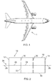
- An aircraft wing 1 shown in Figure 1 contains a number of fuel tank assemblies, one of which is shown schematically in Figure 2 .
- the fuel tank assembly 10 comprises a fuel tank with fore/aft boundary walls provided by front/rear spars (not shown), inboard/outboard boundary walls provided by inboard/outboard sealed ribs 12, 14, and upper/ lower boundary walls provided by upper/lower covers 16, 18.
- the wing also has baffle ribs 20 between the sealed ribs.
- the baffle ribs have holes 22 which permit fuel to flow through them.
- the spars and covers are formed from a composite material such as carbon-fibre reinforced epoxy resin.
- the ribs are formed from a metallic material such as Aluminium.
- a fuel pipe installation 24 is installed in the fuel tank.
- the pipe installation comprises a series of metallic pipes, including external pipes 29 outside the fuel tank, and internal pipes 26, 28 each extending across the width of a bay between ribs.
- Each pipe 26, 28 is metallic along its full length from end to end, and may be manufactured by extrusion.
- Figure 3 is a detailed schematic view of the pipe installation at one of the baffle ribs 20, showing first 26 and second 28 pipes on opposite sides of the rib.
- Each pipe 26, 28 is metallic along its full length from the end shown in Figure 3 , to the opposite end shown in Figure 2 where it is connected to another pipe.
- a fitting 30 passes through a hole in the baffle rib 20, connects the pipes 26, 28, and enables liquid fuel to flow through the pipes via a conduit 34 in the fitting.
- the fitting 30 comprises a body 32 containing the conduit 34, and a flange 36 extending radially from the body.
- the flange 36 is annular, extending around a full circumference of the body.
- the body has a central section 38 passing through the hole in the baffle rib 20 with a reduced inner and outer diameter, and end sections 40 containing sockets which receive the pipes.
- O-rings 42 in the sockets provide a fluid-tight seal and flexible joints which permits relative movement between the fitting and the pipes.
- the conduit 34 in the fitting has an axis which is co-linear with axes 26a, 28a of the pipes 26, 28.
- Each flexible joint permits a sliding axial relative movement between the fitting 30 and the first or second pipe 26, 28 in an axial direction parallel with the axes. This axial relative movement has a range of about 49mm, being the distance between a shoulder 39 at the base of the socket and the rim of the socket.
- Each flexible joint also permits a pivoting relative movement in which the axis 26a, 28a of the first or second pipe pivots relative to the axis of the fitting 30. This pivoting relative movement has a range of the order of 4°.
- the body of the fitting may have a "clam-shell" structure which enables the fitting to be opened up to admit the ends of the pipes, then clamped shut to couple the pipes together whilst permitting relative axial and pivoting movement between them.
- the pipes are straight and rigid with outer diameters between about 20mm and 100mm. This makes them incapable of bending or lengthening as the wing bends or twists during flight.
- the flexible joints with the fitting enable relative movement between the pipes, so that the pipe installation as a whole can accommodate such bending or twisting of the wing.
- the flange 36 is attached to the rib 20 by bolts 44. This rigid attachment between fitting and the rib 20 keeps the fitting centralised within the hole in the rib, and also enables loads to be transferred between the pipes 26, 28 and the rib 20 via the fitting.
- Each bolt has a metallic shaft 46, a metallic head 48 and a metallic nut 50.
- a gasket 52 is sandwiched between opposed faces of the flange 36 and the rib 20. Like the flange 36, the gasket 52 is annular and extends fully around a circumference of the body 32.
- a top-hat insulating bush 54 is inserted into holes in the rib 20, gasket 52 and flange 36 with a head 56 of the bush 54 bearing against the left-hand face of the rib.
- the shaft 46 of the bolt 44 is then inserted until the head 48 contacts the head 56 of the bush 54.
- the nut 50 is screwed on, with an insulating washer 58 sandwiched between the nut 50 and the right-hand face of the flange.
- the nut 50 is tightened so that the gasket 52 is compressed between the opposed faces of the flange 36 and the rib 20.
- the pipe installation 24 mitigates ignition risks as follows.
- One ignition risk is presented by lightning strike. If the upper 18 or lower 16 covers are made from composite material with a high electrical resistance, and the pipe installation 24 has a low electrical resistance, then large currents could flow along the pipes 26, 28 through the fuel tank 10 as a result of a lightning strike to the external surface of the wing and could pose a potential sparking hazard at the interface of the pipes 26, 28 and fitting 30.
- the pipe installation 24 is designed to present a path of least electrical resistance with a resistance higher than 50 ⁇ and typically higher than 100k ⁇ , so that such lightning-induced currents are kept to a safe level.
- the pipes 26, 28 are made of Aluminium so have a very low resistance - of the order of 50 ⁇ from end to end.
- the body 32 and flange 36 of the fitting 30 are formed from a single piece of Aluminium with a very low resistance of a similar magnitude.
- the pipes 26, 28 are connected to the fitting 30 by respective metallic bonding leads 60 (typically nickel-plated copper) to ensure a conductive connection between them (each metallic bonding lead having a very low resistance, of the order of less than 1m ⁇ ).
- the gasket 52 on the other hand is formed from a material with a relatively high electrical resistance - for instance PEEK polymer mixed with conductive filler particles such as carbon black.
- the insulating bush 54 and washer 58 are formed from an insulating material such as PEEK without any carbon black filler particles.
- the path of least electrical resistance between the pipes 26, 28 and the rib 20 has a first portion which passes though the body 32 and the flange 36 (this first portion having a very low resistance - of the order of less than 1m ⁇ ) and a second portion which passes through the gasket 52 between the opposed faces of the flange and the rib, and not through any of the metallic bolts 44 (due to the insulating bush 54, 56 and washer 58).
- the concentration of carbon black in the gasket 52 is tailored to be sufficiently low so that the second portion of the path of least electrical resistance (i.e. the portion across the gasket) has a resistance above 50 ⁇ and typically above 100k ⁇ to ensure that currents resulting from lightning strikes are kept at an acceptable level.
- Another ignition risk is electrostatic discharge.
- the surface of the fuel becomes charged, and this charge could accumulate on the fuel pipes, either by direct contact with the fuel or by inducing voltage in the pipes across an air gap.
- the baffle ribs 20 provide multiple redundant paths for such charge to dissipate.
- the concentration of carbon black in the gasket 52 is tailored to be sufficiently high so that the path of least electrical resistance has a resistance below 100M ⁇ and typically below 10M ⁇ to ensure that current can flow between the pipes 26, 28 and the ribs 20 to dissipate such electrostatic charges.
- each fitting 30 has a relatively high electrical resistance as described above.
- Figure 4 is a detailed schematic view of a pipe installation according to a second embodiment of the invention. Many of the features of the installation of Figure 4 are identical to Figure 3 , and such identical features are labelled with the same reference number.
- the fitting 30a in Figure 4 has no insulating gasket, and the bolts 44 have no insulating bush or washer.
- the body 32a and the flange 36a are formed by injection moulding as a single piece.
- the injection moulding material comprises a thermoplastic polymer mixed with short-strand glass fibres (to provide mechanical strength) and electrically conductive filler particles such as carbon black.
- the concentration of the carbon black is tailored so that the path of least electrical resistance through the body 32a and flange 36a of the fitting between the pipes 26, 28 and the rib 20 has a resistance at a desired value. Similar resistance values to those described above can be achieved across the fitting 30a - i.e. between 50 ⁇ and 10M ⁇ - to mitigate ignition risks.
- FIGS 5 and 6 represent the embodiments of Figures 3 and 4 respectively as electric circuits.
- each fitting 30 provides a path of least electrical resistance between the first or second pipe (26 or 28) and the structure (12, 20 or 14) and this path of least electrical resistance has a resistance R which is between 50 ⁇ and 100M ⁇ .
- the fittings 30 provide negligible electrical resistance between adjacent coupled pipes.
- the external pipes 29 outside the fuel tank at either end are formed from a highly resistive material, rather than metal, so as to provide a high resistance path to prevent hazardous currents flowing into the entire pipe run.
- the external pipes 29 may be metallic but incorporate a highly resistive element for the same purpose.
- each fitting 30a provides a path of least electrical resistance between the first or second pipe (26, 28 or 29) and the structure (12, 20 or 14), and this path of least electrical resistance has a resistance (R1+R3) or (R2+R3) which is between 50 ⁇ and 100M ⁇ .
- the body of each fitting 30a also provides a path of least electrical resistance between the first pipe and the second pipe, and this path of least electrical resistance has a resistance (R1+R2) which is also between 50 ⁇ and 100M ⁇ .
- the external pipes 29 outside the fuel tank can be metallic since the fitting 30a presents a high resistance path (R1+R2) into the fuel tank from the external pipe 29.
- a further source of ignition risk is arcing or surface tracking between the body of the fitting 30 and the baffle rib 20, due to the possible presence of foreign object debris. There are various ways in which this risk can be mitigated.
- the body of the fitting passes through a hole in the baffle rib 20.
- An electrically insulating material is provided in the hole between the body of the fitting and the circular edge of the baffle rib 20, and examples are shown in Figures 7-9 .
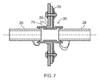
- Figure 7 shows the pipe installation of Figure 3 having a gasket 70 which is flanged and extended relative to the gasket 52 of Figure 3 .
- the gasket 52 of Figure 3 ends at the diameter of the hole through the baffle rib 20
- the gasket 70 of Figure 7 extends into the hole between the baffle rib 20 and the fitting 30.
- the gasket 70 contacts the outer diameter of the fitting 30 and the edge of the rib 20, and has a perpendicular flange or bush 71 located at the inner diameter of the gasket 70 and extending at least partially along the outer diameter of the fitting 30 to a point at or beyond the edge 21 of the rib 20.
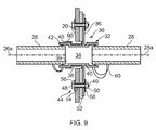
- an electrically insulating coating (typically a painted coating such as top coat paint) can be added to either the rib 20 or the outer diameter of the fitting 30, or potentially to both rib 20 and fitting 30.
- Figure 8 shows the pipe installation of Figure 3 with an electrically insulating coating 80 on the rib 20
- Figure 9 shows the pipe installation of Figure 3 with an electrically insulating coating 90 on the external surface of the fitting 30.
- an insulating coating 80 and/or 90 can be applied as shown in Figures 8 and 9 .
Landscapes
- Engineering & Computer Science (AREA)
- Aviation & Aerospace Engineering (AREA)
- General Engineering & Computer Science (AREA)
- Mechanical Engineering (AREA)
- Life Sciences & Earth Sciences (AREA)
- Sustainable Development (AREA)
- Sustainable Energy (AREA)
- Chemical & Material Sciences (AREA)
- Combustion & Propulsion (AREA)
- Transportation (AREA)
- Cooling, Air Intake And Gas Exhaust, And Fuel Tank Arrangements In Propulsion Units (AREA)
- Rigid Pipes And Flexible Pipes (AREA)
Abstract
Description
- The present invention relates to a pipe installation, typically although not exclusively in an aircraft fuel tank.
-
US2012/0012709 describes a known supporting structure between a fuel pipe and a rib within an aircraft fuel tank. The supporting structure is provided with an insulating section which electrically insulates the pipe and the rib. This prevents a spark discharge between the pipe and the rib. - A first aspect of the present invention provides a pipe installation comprising: conductive first and second pipes installed in a fuel tank; and a fitting which connects the first and second pipes and enables fluid to flow through the pipes via a conduit in the fitting, wherein the fitting is attached to the first or second pipe by a flexible joint which permits relative movement between the fitting and the first or second pipe, the fitting is attached to a structure of the fuel tank, the fitting provides a path of least electrical resistance between the first or second pipe and the structure, and the path of least electrical resistance has a resistance between 50Ω and 100MΩ.
- The fitting may be attached to the structure of the fuel tank to enable load to be transferred between the pipes and the structure via the fitting, or simply to maintain the fitting in a fixed position relative to the structure of the fuel tank. The minimum electrical resistance of the fitting (50Ω) limits the flow of undesirable currents such as those induced by lightning-strike or ground loops. The maximum electrical resistance of the fitting (100MΩ) enables desirable currents to flow, for instance to dissipate electrostatic charge. This can be contrasted with
US2012/0012709 in which the very high resistance of the insulating section prevents the flow of such desirable currents. The flexible joint enables relative movement between the fitting and the first or second pipe, enabling the installation to accommodate deformations of the fuel tank - for instance caused by thermal expansion or bending or twisting of the fuel tank. This can be contrasted withUS2012/0012709 in which a single pipe passes through the rib, and the pipe is rigidly gripped by a clamp so that no relative movement is permitted. The use of conductive pipes with low resistivity, rather than pipes made from a high-resistivity material such as a polymer, enables the pipes to be manufactured easily and cheaply, for instance by extrusion. - Typically the fitting provides a first path of least electrical resistance between the first pipe and the structure and the first path of least electrical resistance has a resistance between 50Ω and 100MΩ, and the fitting also provides a second path of least electrical resistance between the second pipe and the structure and the second path of least electrical resistance has a resistance between 50Ω and 100MΩ.
- Typically the fitting comprises a body containing the conduit, and a flange extending from the body, wherein the fitting is attached to the structure of the fuel tank by the flange. Typically the flange extends radially from the body. In one embodiment the body and the flange are formed from a polymer (typically a thermoplastic polymer) mixed with conductive filler particles, and in another embodiment they are metallic.
- Typically the body of the fitting passes through a hole in the structure of the fuel tank. Optionally an electrically insulating material is provided in the hole between the body of the fitting and the structure of the fuel tank. The electrically insulating material may be for example a coating on the fitting or the structure, or a gasket.
- In one embodiment the fitting further comprises a resistive element (for instance a pad such as an annular gasket) between the flange and the structure, a portion of the path of least electrical resistance passes between the flange and the structure through the resistive element, and the portion of the path of least electrical resistance has a resistance between 50Ω and 100MΩ. In this case the body and the flange are preferably metallic. The resistive element may extend around only part of a circumference of the body, but more preferably it extends fully around a circumference of the body. In another embodiment the body and the flange are formed from a material with a tailored resistivity - such as a polymer mixed with conductive filler particles - and the flange is in direct contact with the structure. In this case the resistivity of the material forming the body and flange is tailored so that the path of least electrical resistance through the body and the flange has a resistance between 50Ω and 100MΩ.
- The flange may be bonded to the structure with an adhesive with a tailored resistivity giving the desired resistance between 50Ω and 100MΩ. However more typically the flange is attached to the structure by fasteners which pass through fastener holes in the flange. Optionally each fastener comprises a metallic body, and an electrically insulating barrier between the metallic body and the flange.
- The flange may extend around only part of a circumference of the body, but more preferably it extends fully around a circumference of the body. Typically the flange is annular. The flange and the body may be different parts, but more preferably they are formed integrally from a single piece of material. Optionally the flange and body are formed integrally by injection moulding.
- The (or each) path of least electrical resistance may have a resistance less than 1kΩ, but more typically it has a resistance greater than 1kΩ, or greater than 10kΩ, and most preferably it has a resistance greater than 100kΩ.
- The (or each) path of least electrical resistance may have a resistance greater than 10MΩ, but more typically it has a resistance less than 10MΩ.
- In a preferred embodiment the (or each) path of least electrical resistance has a resistance between 100kΩ and 10MΩ.
- Optionally the conduit in the fitting has an axis, and the (or each) flexible joint permits an axial relative movement between the fitting and the first or second pipe in an axial direction parallel with the axis. This axial relative movement typically has a permitted range which is greater than 1mm and most preferably greater than 10mm.
- Optionally the (or each) flexible joint permits a pivoting relative movement between the fitting and the first or second pipe in which an axis of the first or second pipe pivots relative to the fitting. This pivoting relative movement typically has a permitted range which is greater than 1° and most preferably greater than 2°.
- The fitting optionally has a first socket which receives the first pipe, and a second socket which receives the second pipe. Alternatively the fitting may be received within the pipes.
- Each conductive pipe typically has a resistance below 1Ω from end to end of the pipe, and preferably much lower.
- Typically the conductive first and second pipes are metallic. For instance they may be formed from a conductive metallic material, such as Aluminium. Such materials are cheap and convenient. The conductive first and second pipes may be metallic along only part of their length, but more preferably the conductive first and second pipes are metallic along their full length, i.e. from end to end. Optionally each pipe is connected to the fitting by one or more respective metallic bonding leads. To provide redundancy in case one lead fails, two bonding leads may be provided at each pipe end. Each metallic bonding lead typically has a resistance below 1Ω, and preferably much lower.
- Optionally the fitting is attached to only one of the pipes by a flexible joint, the joint with the other pipe being rigid. However more preferably the fitting is attached to the first pipe by a first flexible joint which permits relative movement between the fitting and the first pipe, and the fitting is attached to the second pipe by a second flexible joint which permits relative movement between the fitting and the second pipe.
- The fuel tank may be in a fixed structure, but more typically it is a fuel tank of a vehicle such as a ship, train or aircraft.
- The pipes may be for conveying hydraulic liquid or inert gas, but more preferably the first and second pipes are liquid fuel pipes, and the fitting enables liquid fuel (such as kerosene) to flow through the pipes via the conduit in the fitting.
- In the case of hydraulic pipes, the pipes may have outer diameters which are less than 15mm. However in such cases the pipes themselves are typically able to flex, so a flexible joint with the fitting may not be required. Therefore more preferably the first and second pipes have outer diameters which are greater than 15mm, typically greater than 20mm, and most typically greater than 50mm.
- A further aspect of the invention provides a fuel tank assembly comprising a fuel tank; and a pipe installation according to the first aspect of the invention installed in the fuel tank. The fuel tank may be metallic, but more typically the fuel tank has at least one fuel tank wall formed from a composite material.
- Typically the structure of the fuel tank to which the fitting is attached is metallic.
- In a preferred embodiment the structure of the fuel tank to which the fitting is attached is a rib of an aircraft wing. The aircraft wing may comprise a primarily carbon fibre reinforced plastic construction - for instance with carbon fibre reinforced plastic skins and spars.
- Embodiments of the invention will now be described with reference to the accompanying drawings, in which:
-
Figure 1 is a plan view of an aircraft including an aircraft wing with a pipe installation according to an embodiment of the invention; -
Figure 2 is a schematic side view of a fuel tank assembly contained within the wing of the aircraft ofFigure 1 ; -
Figure 3 is a schematic view of a pipe installation according to a first embodiment at one of the baffle ribs ofFigure 2 ; -
Figure 4 is a schematic view of a pipe installation according to a second embodiment at one of the baffle ribs ofFigure 2 ; -
Figure 5 is an electrical circuit for the first embodiment, -
Figure 6 is an electrical circuit for the second embodiment, -
Figure 7 is a schematic view of the pipe installation ofFigure 3 showing an extended, flanged gasket, -
Figure 8 is a schematic view of the pipe installation ofFigure 3 having an insulating coating on the baffle rib; and -
Figure 9 is a schematic view of the pipe installation ofFigure 3 having an insulating coating on the external surface of the fitting. - An aircraft wing 1 shown in
Figure 1 contains a number of fuel tank assemblies, one of which is shown schematically inFigure 2 . Thefuel tank assembly 10 comprises a fuel tank with fore/aft boundary walls provided by front/rear spars (not shown), inboard/outboard boundary walls provided by inboard/outboard sealedribs lower covers baffle ribs 20 between the sealed ribs. The baffle ribs haveholes 22 which permit fuel to flow through them. The spars and covers are formed from a composite material such as carbon-fibre reinforced epoxy resin. The ribs are formed from a metallic material such as Aluminium. - A
fuel pipe installation 24 is installed in the fuel tank. The pipe installation comprises a series of metallic pipes, includingexternal pipes 29 outside the fuel tank, andinternal pipes pipe Figure 3 is a detailed schematic view of the pipe installation at one of thebaffle ribs 20, showing first 26 and second 28 pipes on opposite sides of the rib. Eachpipe Figure 3 , to the opposite end shown inFigure 2 where it is connected to another pipe. A fitting 30 passes through a hole in thebaffle rib 20, connects thepipes conduit 34 in the fitting. - The fitting 30 comprises a
body 32 containing theconduit 34, and aflange 36 extending radially from the body. Theflange 36 is annular, extending around a full circumference of the body. The body has acentral section 38 passing through the hole in thebaffle rib 20 with a reduced inner and outer diameter, and endsections 40 containing sockets which receive the pipes. O-rings 42 in the sockets provide a fluid-tight seal and flexible joints which permits relative movement between the fitting and the pipes. - The
conduit 34 in the fitting has an axis which is co-linear withaxes pipes second pipe shoulder 39 at the base of the socket and the rim of the socket. Each flexible joint also permits a pivoting relative movement in which theaxis - In an alternative embodiment (not shown) the body of the fitting may have a "clam-shell" structure which enables the fitting to be opened up to admit the ends of the pipes, then clamped shut to couple the pipes together whilst permitting relative axial and pivoting movement between them.
- The pipes are straight and rigid with outer diameters between about 20mm and 100mm. This makes them incapable of bending or lengthening as the wing bends or twists during flight. The flexible joints with the fitting enable relative movement between the pipes, so that the pipe installation as a whole can accommodate such bending or twisting of the wing.
- The
flange 36 is attached to therib 20 bybolts 44. This rigid attachment between fitting and therib 20 keeps the fitting centralised within the hole in the rib, and also enables loads to be transferred between thepipes rib 20 via the fitting. Each bolt has ametallic shaft 46, ametallic head 48 and ametallic nut 50. Agasket 52 is sandwiched between opposed faces of theflange 36 and therib 20. Like theflange 36, thegasket 52 is annular and extends fully around a circumference of thebody 32. - A top-
hat insulating bush 54 is inserted into holes in therib 20,gasket 52 andflange 36 with ahead 56 of thebush 54 bearing against the left-hand face of the rib. Theshaft 46 of thebolt 44 is then inserted until thehead 48 contacts thehead 56 of thebush 54. Then thenut 50 is screwed on, with an insulatingwasher 58 sandwiched between thenut 50 and the right-hand face of the flange. Thenut 50 is tightened so that thegasket 52 is compressed between the opposed faces of theflange 36 and therib 20. - The
pipe installation 24 mitigates ignition risks as follows. One ignition risk is presented by lightning strike. If the upper 18 or lower 16 covers are made from composite material with a high electrical resistance, and thepipe installation 24 has a low electrical resistance, then large currents could flow along thepipes fuel tank 10 as a result of a lightning strike to the external surface of the wing and could pose a potential sparking hazard at the interface of thepipes fitting 30. For this reason thepipe installation 24 is designed to present a path of least electrical resistance with a resistance higher than 50Ω and typically higher than 100kΩ, so that such lightning-induced currents are kept to a safe level. Thepipes body 32 andflange 36 of the fitting 30 are formed from a single piece of Aluminium with a very low resistance of a similar magnitude. Thepipes gasket 52 on the other hand is formed from a material with a relatively high electrical resistance - for instance PEEK polymer mixed with conductive filler particles such as carbon black. The insulatingbush 54 andwasher 58 are formed from an insulating material such as PEEK without any carbon black filler particles. Hence the path of least electrical resistance between thepipes rib 20 has a first portion which passes though thebody 32 and the flange 36 (this first portion having a very low resistance - of the order of less than 1mΩ) and a second portion which passes through thegasket 52 between the opposed faces of the flange and the rib, and not through any of the metallic bolts 44 (due to the insulatingbush gasket 52 is tailored to be sufficiently low so that the second portion of the path of least electrical resistance (i.e. the portion across the gasket) has a resistance above 50Ω and typically above 100kΩ to ensure that currents resulting from lightning strikes are kept at an acceptable level. - Another ignition risk is electrostatic discharge. As fuel is pumped into the tank, the surface of the fuel becomes charged, and this charge could accumulate on the fuel pipes, either by direct contact with the fuel or by inducing voltage in the pipes across an air gap. It is desirable that the
baffle ribs 20 provide multiple redundant paths for such charge to dissipate. For this reason the concentration of carbon black in thegasket 52 is tailored to be sufficiently high so that the path of least electrical resistance has a resistance below 100MΩ and typically below 10MΩ to ensure that current can flow between thepipes ribs 20 to dissipate such electrostatic charges. - Another ignition risk is ground loop currents. If a conductive object (such as a spanner) is left in the
fuel tank 10 in contact with one of thepipes -
Figure 4 is a detailed schematic view of a pipe installation according to a second embodiment of the invention. Many of the features of the installation ofFigure 4 are identical toFigure 3 , and such identical features are labelled with the same reference number. - The fitting 30a in
Figure 4 has no insulating gasket, and thebolts 44 have no insulating bush or washer. Thebody 32a and theflange 36a are formed by injection moulding as a single piece. The injection moulding material comprises a thermoplastic polymer mixed with short-strand glass fibres (to provide mechanical strength) and electrically conductive filler particles such as carbon black. The concentration of the carbon black is tailored so that the path of least electrical resistance through thebody 32a andflange 36a of the fitting between thepipes rib 20 has a resistance at a desired value. Similar resistance values to those described above can be achieved across the fitting 30a - i.e. between 50Ω and 10MΩ - to mitigate ignition risks. -
Figures 5 and 6 represent the embodiments ofFigures 3 and 4 respectively as electric circuits. In the embodiment ofFigure 3 each fitting 30 provides a path of least electrical resistance between the first or second pipe (26 or 28) and the structure (12, 20 or 14) and this path of least electrical resistance has a resistance R which is between 50Ω and 100MΩ. However thefittings 30 provide negligible electrical resistance between adjacent coupled pipes. For this reason, theexternal pipes 29 outside the fuel tank at either end are formed from a highly resistive material, rather than metal, so as to provide a high resistance path to prevent hazardous currents flowing into the entire pipe run. Alternatively theexternal pipes 29 may be metallic but incorporate a highly resistive element for the same purpose. - In the embodiment of
Figure 4 the body and flange of each fitting 30a provides a path of least electrical resistance between the first or second pipe (26, 28 or 29) and the structure (12, 20 or 14), and this path of least electrical resistance has a resistance (R1+R3) or (R2+R3) which is between 50Ω and 100MΩ. The body of each fitting 30a also provides a path of least electrical resistance between the first pipe and the second pipe, and this path of least electrical resistance has a resistance (R1+R2) which is also between 50Ω and 100MΩ. In this case, unlike in the example ofFigure 5 , theexternal pipes 29 outside the fuel tank can be metallic since the fitting 30a presents a high resistance path (R1+R2) into the fuel tank from theexternal pipe 29. - A further source of ignition risk is arcing or surface tracking between the body of the fitting 30 and the
baffle rib 20, due to the possible presence of foreign object debris. There are various ways in which this risk can be mitigated. - The body of the fitting passes through a hole in the
baffle rib 20. An electrically insulating material is provided in the hole between the body of the fitting and the circular edge of thebaffle rib 20, and examples are shown inFigures 7-9 . -
Figure 7 shows the pipe installation ofFigure 3 having agasket 70 which is flanged and extended relative to thegasket 52 ofFigure 3 . Whereas thegasket 52 ofFigure 3 ends at the diameter of the hole through thebaffle rib 20, thegasket 70 ofFigure 7 extends into the hole between thebaffle rib 20 and the fitting 30. Thegasket 70 contacts the outer diameter of the fitting 30 and the edge of therib 20, and has a perpendicular flange orbush 71 located at the inner diameter of thegasket 70 and extending at least partially along the outer diameter of the fitting 30 to a point at or beyond theedge 21 of therib 20. - Alternatively, as shown in
Figures 8 and9 , an electrically insulating coating (typically a painted coating such as top coat paint) can be added to either therib 20 or the outer diameter of the fitting 30, or potentially to bothrib 20 andfitting 30.Figure 8 shows the pipe installation ofFigure 3 with an electrically insulatingcoating 80 on therib 20, andFigure 9 shows the pipe installation ofFigure 3 with an electrically insulatingcoating 90 on the external surface of the fitting 30. In the embodiment shown inFigure 4 where the fitting provides the resistive functionality and nogasket coating 80 and/or 90 can be applied as shown inFigures 8 and9 . - Although the invention has been described above with reference to one or more preferred embodiments, it will be appreciated that various changes or modifications may be made without departing from the scope of the invention as defined in the appended claims.
Claims (15)
- A pipe installation comprising: conductive first and second pipes installed in a fuel tank; and a fitting which connects the first and second pipes and enables fluid to flow through the pipes via a conduit in the fitting, wherein the fitting is attached to the first or second pipe by a flexible joint which permits relative movement between the fitting and the first or second pipe, the fitting is attached to a structure of the fuel tank, the fitting provides a path of least electrical resistance between the first or second pipe and the structure, and the path of least electrical resistance has a resistance between 50Ω and 100MΩ.
- The pipe installation of claim 1 wherein the fitting comprises a body containing the conduit, and a flange extending from the body, wherein the fitting is attached to the structure of the fuel tank by the flange.
- The pipe installation of claim 2 wherein the body and the flange are formed from a polymer mixed with conductive filler particles.
- The pipe installation of claim 2 wherein the fitting further comprises a resistive element between the flange and the structure, a portion of the path of least electrical resistance passes between the flange and the structure through the resistive element, and the portion of the path of least electrical resistance has a resistance between 50Ω and 100MΩ.
- The pipe installation of any of claims 2 to 4 wherein the flange is attached to the structure by fasteners which pass through holes in the flange.
- The pipe installation of claim 4 and claim 5 wherein each fastener comprises a metallic body, and an electrically insulating barrier between the metallic body and the flange.
- The pipe installation of any preceding claim wherein the path of least electrical resistance has a resistance greater than 1kΩ, or greater than 10kΩ, or greater than 100kΩ.
- The pipe installation of any preceding claim wherein the path of least electrical resistance has a resistance less than 10MΩ.
- The pipe installation of any preceding claim wherein the conduit in the fitting has an axis, and the flexible joint permits an axial relative movement between the fitting and the first or second pipe in an axial direction parallel with the axis; or the flexible joint permits a pivoting relative movement between the fitting and the first or second pipe in which an axis of the first or second pipe pivots relative to the fitting.
- The pipe installation of claim 9 wherein the axial relative movement has a permitted range greater than 1mm or 10mm; or the pivoting relative movement has a permitted range greater than 1° or greater than 2°.
- The pipe installation of any preceding claim wherein the fitting is attached to the first pipe by a first flexible joint which permits relative movement between the fitting and the first pipe, and the fitting is attached to the second pipe by a second flexible joint which permits relative movement between the fitting and the second pipe.
- The pipe installation of any preceding claim wherein the fuel tank is an aircraft fuel tank.
- The pipe installation of any preceding claim wherein each conductive pipe has a resistance below 1Ω from end to end of the pipe.
- A fuel tank assembly comprising a fuel tank; and a pipe installation according to any preceding claim installed in the fuel tank, wherein the fuel tank has at least one fuel tank wall formed from a composite material.
- An aircraft wing comprising a fuel tank assembly according to claim 14.
Applications Claiming Priority (1)
| Application Number | Priority Date | Filing Date | Title |
|---|---|---|---|
| GB1515860.3A GB2542121A (en) | 2015-09-08 | 2015-09-08 | Pipe installation |
Publications (2)
| Publication Number | Publication Date |
|---|---|
| EP3141484A1 true EP3141484A1 (en) | 2017-03-15 |
| EP3141484B1 EP3141484B1 (en) | 2021-03-31 |
Family
ID=54345905
Family Applications (1)
| Application Number | Title | Priority Date | Filing Date |
|---|---|---|---|
| EP16185573.9A Active EP3141484B1 (en) | 2015-09-08 | 2016-08-24 | Pipe installation |
Country Status (4)
| Country | Link |
|---|---|
| US (1) | US10293952B2 (en) |
| EP (1) | EP3141484B1 (en) |
| CN (1) | CN106494607A (en) |
| GB (1) | GB2542121A (en) |
Cited By (2)
| Publication number | Priority date | Publication date | Assignee | Title |
|---|---|---|---|---|
| EP3611097A1 (en) * | 2018-08-15 | 2020-02-19 | Short Brothers Plc | Electrical isolator fitting |
| WO2020039076A1 (en) * | 2018-08-24 | 2020-02-27 | Plastic Omnium Advanced Innovation And Research | Assembly for a fluid tank comprising a baffle and a fluid transfer line passing through the baffle |
Families Citing this family (10)
| Publication number | Priority date | Publication date | Assignee | Title |
|---|---|---|---|---|
| JP6661369B2 (en) * | 2015-12-25 | 2020-03-11 | 三菱航空機株式会社 | Seat between high-temperature duct and structural member of aircraft, aircraft duct structure, and aircraft |
| JP2018123766A (en) * | 2017-02-01 | 2018-08-09 | トヨタ自動車株式会社 | Fuel pipeline support structure |
| GB2572553A (en) | 2018-03-29 | 2019-10-09 | Airbus Operations Ltd | Aircraft fuel tank isolator |
| GB2575977A (en) * | 2018-07-30 | 2020-02-05 | Airbus Operations Ltd | Support member |
| US11332258B2 (en) * | 2018-09-27 | 2022-05-17 | Textron Innovations Inc. | Method for enhanced fuel cell protection from adjacent damaged components |
| EP3719369B1 (en) * | 2019-04-02 | 2025-02-12 | Crompton Technology Group Limited | Electrical isolator and method of making thereof |
| TWI786596B (en) * | 2020-04-17 | 2022-12-11 | 美商恩特葛瑞斯股份有限公司 | Electrostatic discharge mitigation device and fluid circuit having the same |
| CN113184215B (en) * | 2021-03-31 | 2022-06-14 | 成都飞机工业(集团)有限责任公司 | Method for installing aircraft skin exhaust guide pipe |
| US20250361020A1 (en) * | 2022-06-14 | 2025-11-27 | Airbus Operations Limited | An aircraft assembly |
| GB2632619A (en) | 2022-11-25 | 2025-02-19 | Airbus Operations Ltd | Aircraft assembly |
Citations (4)
| Publication number | Priority date | Publication date | Assignee | Title |
|---|---|---|---|---|
| EP0269458A1 (en) * | 1986-11-28 | 1988-06-01 | British Aerospace Public Limited Company | Anti-lightning strike fasteners for composite material aircraft structures |
| US20100003840A1 (en) * | 2008-07-02 | 2010-01-07 | Eaton Corporation | Dielectric Isolators |
| US20100226063A1 (en) * | 2009-03-09 | 2010-09-09 | Airbus Operations Limited | Aircraft joint and bonding lead |
| US20120057267A1 (en) * | 2010-09-06 | 2012-03-08 | Airbus Operations Limited | Pipe connector |
Family Cites Families (8)
| Publication number | Priority date | Publication date | Assignee | Title |
|---|---|---|---|---|
| GB0523573D0 (en) * | 2005-11-18 | 2005-12-28 | Airbus Uk Ltd | Aircraft fuel pipe coupling |
| US8956556B2 (en) * | 2008-07-02 | 2015-02-17 | Eaton Corporation | Dielectric isolators |
| FR2938624B1 (en) * | 2008-11-20 | 2010-12-24 | Espa | DEVICE FOR CARRYING OUT A FLUID, IN PARTICULAR FOR FUEL |
| JP5210925B2 (en) | 2009-02-27 | 2013-06-12 | 三菱重工業株式会社 | Fuel tank ignition prevention structure |
| FR2948254B1 (en) * | 2009-07-16 | 2011-12-30 | Airbus Operations Sas | DEVICE FOR PROTECTING PIPES AGAINST LIGHTNING |
| US8783735B2 (en) * | 2011-10-24 | 2014-07-22 | The Boeing Company | Conductance on hydraulic fittings using a soft metal interlayer |
| US9739402B2 (en) * | 2013-03-04 | 2017-08-22 | Eaton Corporation | Electrically conductive seals for fluid conveyance systems |
| US10001235B2 (en) * | 2014-01-29 | 2018-06-19 | Garlock Pipeline Technologies, Inc. | Sealing system having interlocking inner diameter seal element to resist pressure changes |
-
2015
- 2015-09-08 GB GB1515860.3A patent/GB2542121A/en not_active Withdrawn
-
2016
- 2016-08-24 EP EP16185573.9A patent/EP3141484B1/en active Active
- 2016-09-08 US US15/259,901 patent/US10293952B2/en active Active
- 2016-09-08 CN CN201610810383.8A patent/CN106494607A/en active Pending
Patent Citations (4)
| Publication number | Priority date | Publication date | Assignee | Title |
|---|---|---|---|---|
| EP0269458A1 (en) * | 1986-11-28 | 1988-06-01 | British Aerospace Public Limited Company | Anti-lightning strike fasteners for composite material aircraft structures |
| US20100003840A1 (en) * | 2008-07-02 | 2010-01-07 | Eaton Corporation | Dielectric Isolators |
| US20100226063A1 (en) * | 2009-03-09 | 2010-09-09 | Airbus Operations Limited | Aircraft joint and bonding lead |
| US20120057267A1 (en) * | 2010-09-06 | 2012-03-08 | Airbus Operations Limited | Pipe connector |
Cited By (4)
| Publication number | Priority date | Publication date | Assignee | Title |
|---|---|---|---|---|
| EP3611097A1 (en) * | 2018-08-15 | 2020-02-19 | Short Brothers Plc | Electrical isolator fitting |
| US11352147B2 (en) | 2018-08-15 | 2022-06-07 | Short Brothers Plc | Electrical isolator fitting |
| WO2020039076A1 (en) * | 2018-08-24 | 2020-02-27 | Plastic Omnium Advanced Innovation And Research | Assembly for a fluid tank comprising a baffle and a fluid transfer line passing through the baffle |
| US11541745B2 (en) | 2018-08-24 | 2023-01-03 | Plastic Omnium Advanced Innovation And Research | Assembly for a fluid tank comprising a baffle and a fluid transfer line passing through the baffle |
Also Published As
| Publication number | Publication date |
|---|---|
| GB2542121A (en) | 2017-03-15 |
| US10293952B2 (en) | 2019-05-21 |
| GB201515860D0 (en) | 2015-10-21 |
| CN106494607A (en) | 2017-03-15 |
| US20170066542A1 (en) | 2017-03-09 |
| EP3141484B1 (en) | 2021-03-31 |
Similar Documents
| Publication | Publication Date | Title |
|---|---|---|
| EP3141484B1 (en) | Pipe installation | |
| EP2672157B1 (en) | Conductive coupling assembly | |
| US8654499B2 (en) | Pipe connector | |
| EP2900558B1 (en) | Method and apparatus for covering a fastener system | |
| EP2791565B1 (en) | Ferrule protected from electrostatic discharge | |
| AU2013205236B2 (en) | Fluid transport system for preventing electrical discharge |
Legal Events
| Date | Code | Title | Description |
|---|---|---|---|
| PUAI | Public reference made under article 153(3) epc to a published international application that has entered the european phase |
Free format text: ORIGINAL CODE: 0009012 |
|
| STAA | Information on the status of an ep patent application or granted ep patent |
Free format text: STATUS: THE APPLICATION HAS BEEN PUBLISHED |
|
| AK | Designated contracting states |
Kind code of ref document: A1 Designated state(s): AL AT BE BG CH CY CZ DE DK EE ES FI FR GB GR HR HU IE IS IT LI LT LU LV MC MK MT NL NO PL PT RO RS SE SI SK SM TR |
|
| AX | Request for extension of the european patent |
Extension state: BA ME |
|
| STAA | Information on the status of an ep patent application or granted ep patent |
Free format text: STATUS: REQUEST FOR EXAMINATION WAS MADE |
|
| 17P | Request for examination filed |
Effective date: 20170728 |
|
| RBV | Designated contracting states (corrected) |
Designated state(s): AL AT BE BG CH CY CZ DE DK EE ES FI FR GB GR HR HU IE IS IT LI LT LU LV MC MK MT NL NO PL PT RO RS SE SI SK SM TR |
|
| STAA | Information on the status of an ep patent application or granted ep patent |
Free format text: STATUS: EXAMINATION IS IN PROGRESS |
|
| 17Q | First examination report despatched |
Effective date: 20180406 |
|
| GRAP | Despatch of communication of intention to grant a patent |
Free format text: ORIGINAL CODE: EPIDOSNIGR1 |
|
| STAA | Information on the status of an ep patent application or granted ep patent |
Free format text: STATUS: GRANT OF PATENT IS INTENDED |
|
| INTG | Intention to grant announced |
Effective date: 20191218 |
|
| RIN1 | Information on inventor provided before grant (corrected) |
Inventor name: POUT, ALAN Inventor name: JAMES, DYLAN |
|
| GRAJ | Information related to disapproval of communication of intention to grant by the applicant or resumption of examination proceedings by the epo deleted |
Free format text: ORIGINAL CODE: EPIDOSDIGR1 |
|
| STAA | Information on the status of an ep patent application or granted ep patent |
Free format text: STATUS: EXAMINATION IS IN PROGRESS |
|
| INTC | Intention to grant announced (deleted) | ||
| GRAP | Despatch of communication of intention to grant a patent |
Free format text: ORIGINAL CODE: EPIDOSNIGR1 |
|
| STAA | Information on the status of an ep patent application or granted ep patent |
Free format text: STATUS: GRANT OF PATENT IS INTENDED |
|
| INTG | Intention to grant announced |
Effective date: 20200603 |
|
| GRAJ | Information related to disapproval of communication of intention to grant by the applicant or resumption of examination proceedings by the epo deleted |
Free format text: ORIGINAL CODE: EPIDOSDIGR1 |
|
| STAA | Information on the status of an ep patent application or granted ep patent |
Free format text: STATUS: EXAMINATION IS IN PROGRESS |
|
| GRAP | Despatch of communication of intention to grant a patent |
Free format text: ORIGINAL CODE: EPIDOSNIGR1 |
|
| STAA | Information on the status of an ep patent application or granted ep patent |
Free format text: STATUS: GRANT OF PATENT IS INTENDED |
|
| INTC | Intention to grant announced (deleted) | ||
| INTG | Intention to grant announced |
Effective date: 20201028 |
|
| GRAS | Grant fee paid |
Free format text: ORIGINAL CODE: EPIDOSNIGR3 |
|
| GRAA | (expected) grant |
Free format text: ORIGINAL CODE: 0009210 |
|
| STAA | Information on the status of an ep patent application or granted ep patent |
Free format text: STATUS: THE PATENT HAS BEEN GRANTED |
|
| AK | Designated contracting states |
Kind code of ref document: B1 Designated state(s): AL AT BE BG CH CY CZ DE DK EE ES FI FR GB GR HR HU IE IS IT LI LT LU LV MC MK MT NL NO PL PT RO RS SE SI SK SM TR |
|
| REG | Reference to a national code |
Ref country code: GB Ref legal event code: FG4D Ref country code: CH Ref legal event code: EP |
|
| REG | Reference to a national code |
Ref country code: AT Ref legal event code: REF Ref document number: 1376676 Country of ref document: AT Kind code of ref document: T Effective date: 20210415 |
|
| REG | Reference to a national code |
Ref country code: DE Ref legal event code: R096 Ref document number: 602016055131 Country of ref document: DE |
|
| REG | Reference to a national code |
Ref country code: IE Ref legal event code: FG4D |
|
| REG | Reference to a national code |
Ref country code: LT Ref legal event code: MG9D |
|
| PG25 | Lapsed in a contracting state [announced via postgrant information from national office to epo] |
Ref country code: BG Free format text: LAPSE BECAUSE OF FAILURE TO SUBMIT A TRANSLATION OF THE DESCRIPTION OR TO PAY THE FEE WITHIN THE PRESCRIBED TIME-LIMIT Effective date: 20210630 Ref country code: HR Free format text: LAPSE BECAUSE OF FAILURE TO SUBMIT A TRANSLATION OF THE DESCRIPTION OR TO PAY THE FEE WITHIN THE PRESCRIBED TIME-LIMIT Effective date: 20210331 Ref country code: FI Free format text: LAPSE BECAUSE OF FAILURE TO SUBMIT A TRANSLATION OF THE DESCRIPTION OR TO PAY THE FEE WITHIN THE PRESCRIBED TIME-LIMIT Effective date: 20210331 Ref country code: NO Free format text: LAPSE BECAUSE OF FAILURE TO SUBMIT A TRANSLATION OF THE DESCRIPTION OR TO PAY THE FEE WITHIN THE PRESCRIBED TIME-LIMIT Effective date: 20210630 |
|
| PG25 | Lapsed in a contracting state [announced via postgrant information from national office to epo] |
Ref country code: SE Free format text: LAPSE BECAUSE OF FAILURE TO SUBMIT A TRANSLATION OF THE DESCRIPTION OR TO PAY THE FEE WITHIN THE PRESCRIBED TIME-LIMIT Effective date: 20210331 Ref country code: RS Free format text: LAPSE BECAUSE OF FAILURE TO SUBMIT A TRANSLATION OF THE DESCRIPTION OR TO PAY THE FEE WITHIN THE PRESCRIBED TIME-LIMIT Effective date: 20210331 Ref country code: LV Free format text: LAPSE BECAUSE OF FAILURE TO SUBMIT A TRANSLATION OF THE DESCRIPTION OR TO PAY THE FEE WITHIN THE PRESCRIBED TIME-LIMIT Effective date: 20210331 |
|
| REG | Reference to a national code |
Ref country code: NL Ref legal event code: MP Effective date: 20210331 |
|
| REG | Reference to a national code |
Ref country code: AT Ref legal event code: MK05 Ref document number: 1376676 Country of ref document: AT Kind code of ref document: T Effective date: 20210331 |
|
| PG25 | Lapsed in a contracting state [announced via postgrant information from national office to epo] |
Ref country code: AT Free format text: LAPSE BECAUSE OF FAILURE TO SUBMIT A TRANSLATION OF THE DESCRIPTION OR TO PAY THE FEE WITHIN THE PRESCRIBED TIME-LIMIT Effective date: 20210331 Ref country code: SM Free format text: LAPSE BECAUSE OF FAILURE TO SUBMIT A TRANSLATION OF THE DESCRIPTION OR TO PAY THE FEE WITHIN THE PRESCRIBED TIME-LIMIT Effective date: 20210331 Ref country code: EE Free format text: LAPSE BECAUSE OF FAILURE TO SUBMIT A TRANSLATION OF THE DESCRIPTION OR TO PAY THE FEE WITHIN THE PRESCRIBED TIME-LIMIT Effective date: 20210331 Ref country code: CZ Free format text: LAPSE BECAUSE OF FAILURE TO SUBMIT A TRANSLATION OF THE DESCRIPTION OR TO PAY THE FEE WITHIN THE PRESCRIBED TIME-LIMIT Effective date: 20210331 Ref country code: NL Free format text: LAPSE BECAUSE OF FAILURE TO SUBMIT A TRANSLATION OF THE DESCRIPTION OR TO PAY THE FEE WITHIN THE PRESCRIBED TIME-LIMIT Effective date: 20210331 Ref country code: LT Free format text: LAPSE BECAUSE OF FAILURE TO SUBMIT A TRANSLATION OF THE DESCRIPTION OR TO PAY THE FEE WITHIN THE PRESCRIBED TIME-LIMIT Effective date: 20210331 |
|
| PG25 | Lapsed in a contracting state [announced via postgrant information from national office to epo] |
Ref country code: PL Free format text: LAPSE BECAUSE OF FAILURE TO SUBMIT A TRANSLATION OF THE DESCRIPTION OR TO PAY THE FEE WITHIN THE PRESCRIBED TIME-LIMIT Effective date: 20210331 Ref country code: PT Free format text: LAPSE BECAUSE OF FAILURE TO SUBMIT A TRANSLATION OF THE DESCRIPTION OR TO PAY THE FEE WITHIN THE PRESCRIBED TIME-LIMIT Effective date: 20210802 Ref country code: ES Free format text: LAPSE BECAUSE OF FAILURE TO SUBMIT A TRANSLATION OF THE DESCRIPTION OR TO PAY THE FEE WITHIN THE PRESCRIBED TIME-LIMIT Effective date: 20210331 Ref country code: SK Free format text: LAPSE BECAUSE OF FAILURE TO SUBMIT A TRANSLATION OF THE DESCRIPTION OR TO PAY THE FEE WITHIN THE PRESCRIBED TIME-LIMIT Effective date: 20210331 Ref country code: RO Free format text: LAPSE BECAUSE OF FAILURE TO SUBMIT A TRANSLATION OF THE DESCRIPTION OR TO PAY THE FEE WITHIN THE PRESCRIBED TIME-LIMIT Effective date: 20210331 Ref country code: IS Free format text: LAPSE BECAUSE OF FAILURE TO SUBMIT A TRANSLATION OF THE DESCRIPTION OR TO PAY THE FEE WITHIN THE PRESCRIBED TIME-LIMIT Effective date: 20210731 |
|
| REG | Reference to a national code |
Ref country code: DE Ref legal event code: R097 Ref document number: 602016055131 Country of ref document: DE |
|
| PG25 | Lapsed in a contracting state [announced via postgrant information from national office to epo] |
Ref country code: AL Free format text: LAPSE BECAUSE OF FAILURE TO SUBMIT A TRANSLATION OF THE DESCRIPTION OR TO PAY THE FEE WITHIN THE PRESCRIBED TIME-LIMIT Effective date: 20210331 Ref country code: DK Free format text: LAPSE BECAUSE OF FAILURE TO SUBMIT A TRANSLATION OF THE DESCRIPTION OR TO PAY THE FEE WITHIN THE PRESCRIBED TIME-LIMIT Effective date: 20210331 |
|
| PLBE | No opposition filed within time limit |
Free format text: ORIGINAL CODE: 0009261 |
|
| STAA | Information on the status of an ep patent application or granted ep patent |
Free format text: STATUS: NO OPPOSITION FILED WITHIN TIME LIMIT |
|
| 26N | No opposition filed |
Effective date: 20220104 |
|
| REG | Reference to a national code |
Ref country code: CH Ref legal event code: PL |
|
| PG25 | Lapsed in a contracting state [announced via postgrant information from national office to epo] |
Ref country code: MC Free format text: LAPSE BECAUSE OF FAILURE TO SUBMIT A TRANSLATION OF THE DESCRIPTION OR TO PAY THE FEE WITHIN THE PRESCRIBED TIME-LIMIT Effective date: 20210331 |
|
| REG | Reference to a national code |
Ref country code: BE Ref legal event code: MM Effective date: 20210831 |
|
| PG25 | Lapsed in a contracting state [announced via postgrant information from national office to epo] |
Ref country code: LI Free format text: LAPSE BECAUSE OF NON-PAYMENT OF DUE FEES Effective date: 20210831 Ref country code: CH Free format text: LAPSE BECAUSE OF NON-PAYMENT OF DUE FEES Effective date: 20210831 |
|
| PG25 | Lapsed in a contracting state [announced via postgrant information from national office to epo] |
Ref country code: IS Free format text: LAPSE BECAUSE OF FAILURE TO SUBMIT A TRANSLATION OF THE DESCRIPTION OR TO PAY THE FEE WITHIN THE PRESCRIBED TIME-LIMIT Effective date: 20210731 Ref country code: LU Free format text: LAPSE BECAUSE OF NON-PAYMENT OF DUE FEES Effective date: 20210824 |
|
| PG25 | Lapsed in a contracting state [announced via postgrant information from national office to epo] |
Ref country code: IT Free format text: LAPSE BECAUSE OF FAILURE TO SUBMIT A TRANSLATION OF THE DESCRIPTION OR TO PAY THE FEE WITHIN THE PRESCRIBED TIME-LIMIT Effective date: 20210331 Ref country code: IE Free format text: LAPSE BECAUSE OF NON-PAYMENT OF DUE FEES Effective date: 20210824 Ref country code: BE Free format text: LAPSE BECAUSE OF NON-PAYMENT OF DUE FEES Effective date: 20210831 |
|
| PG25 | Lapsed in a contracting state [announced via postgrant information from national office to epo] |
Ref country code: HU Free format text: LAPSE BECAUSE OF FAILURE TO SUBMIT A TRANSLATION OF THE DESCRIPTION OR TO PAY THE FEE WITHIN THE PRESCRIBED TIME-LIMIT; INVALID AB INITIO Effective date: 20160824 |
|
| PG25 | Lapsed in a contracting state [announced via postgrant information from national office to epo] |
Ref country code: CY Free format text: LAPSE BECAUSE OF FAILURE TO SUBMIT A TRANSLATION OF THE DESCRIPTION OR TO PAY THE FEE WITHIN THE PRESCRIBED TIME-LIMIT Effective date: 20210331 |
|
| PG25 | Lapsed in a contracting state [announced via postgrant information from national office to epo] |
Ref country code: GR Free format text: LAPSE BECAUSE OF FAILURE TO SUBMIT A TRANSLATION OF THE DESCRIPTION OR TO PAY THE FEE WITHIN THE PRESCRIBED TIME-LIMIT Effective date: 20210331 |
|
| PG25 | Lapsed in a contracting state [announced via postgrant information from national office to epo] |
Ref country code: MK Free format text: LAPSE BECAUSE OF FAILURE TO SUBMIT A TRANSLATION OF THE DESCRIPTION OR TO PAY THE FEE WITHIN THE PRESCRIBED TIME-LIMIT Effective date: 20210331 |
|
| PG25 | Lapsed in a contracting state [announced via postgrant information from national office to epo] |
Ref country code: TR Free format text: LAPSE BECAUSE OF FAILURE TO SUBMIT A TRANSLATION OF THE DESCRIPTION OR TO PAY THE FEE WITHIN THE PRESCRIBED TIME-LIMIT Effective date: 20210331 |
|
| PG25 | Lapsed in a contracting state [announced via postgrant information from national office to epo] |
Ref country code: MT Free format text: LAPSE BECAUSE OF FAILURE TO SUBMIT A TRANSLATION OF THE DESCRIPTION OR TO PAY THE FEE WITHIN THE PRESCRIBED TIME-LIMIT Effective date: 20210331 |
|
| PGFP | Annual fee paid to national office [announced via postgrant information from national office to epo] |
Ref country code: DE Payment date: 20250820 Year of fee payment: 10 |
|
| PGFP | Annual fee paid to national office [announced via postgrant information from national office to epo] |
Ref country code: GB Payment date: 20250820 Year of fee payment: 10 |
|
| PGFP | Annual fee paid to national office [announced via postgrant information from national office to epo] |
Ref country code: FR Payment date: 20250829 Year of fee payment: 10 |