EP3141390A1 - Liquid ejecting apparatus - Google Patents
Liquid ejecting apparatus Download PDFInfo
- Publication number
- EP3141390A1 EP3141390A1 EP16187617.2A EP16187617A EP3141390A1 EP 3141390 A1 EP3141390 A1 EP 3141390A1 EP 16187617 A EP16187617 A EP 16187617A EP 3141390 A1 EP3141390 A1 EP 3141390A1
- Authority
- EP
- European Patent Office
- Prior art keywords
- liquid
- protective member
- liquid ejecting
- ejecting section
- wiping
- Prior art date
- Legal status (The legal status is an assumption and is not a legal conclusion. Google has not performed a legal analysis and makes no representation as to the accuracy of the status listed.)
- Granted
Links
- 239000007788 liquid Substances 0.000 title claims abstract description 352
- 230000001681 protective effect Effects 0.000 claims abstract description 148
- 230000007246 mechanism Effects 0.000 claims description 32
- 238000004140 cleaning Methods 0.000 claims description 22
- 239000005871 repellent Substances 0.000 claims description 14
- 239000000463 material Substances 0.000 description 27
- 239000003595 mist Substances 0.000 description 23
- 238000001035 drying Methods 0.000 description 11
- 238000012423 maintenance Methods 0.000 description 6
- 230000003247 decreasing effect Effects 0.000 description 5
- 238000002156 mixing Methods 0.000 description 5
- 238000011144 upstream manufacturing Methods 0.000 description 4
- 230000008859 change Effects 0.000 description 3
- 239000000428 dust Substances 0.000 description 3
- 239000004744 fabric Substances 0.000 description 3
- 230000004044 response Effects 0.000 description 3
- 230000008901 benefit Effects 0.000 description 2
- 230000007423 decrease Effects 0.000 description 2
- 238000011010 flushing procedure Methods 0.000 description 2
- 239000011344 liquid material Substances 0.000 description 2
- 230000005499 meniscus Effects 0.000 description 2
- 239000000049 pigment Substances 0.000 description 2
- 239000000843 powder Substances 0.000 description 2
- 230000001105 regulatory effect Effects 0.000 description 2
- 239000011347 resin Substances 0.000 description 2
- 229920005989 resin Polymers 0.000 description 2
- 238000007789 sealing Methods 0.000 description 2
- 238000004062 sedimentation Methods 0.000 description 2
- 238000004040 coloring Methods 0.000 description 1
- 238000011109 contamination Methods 0.000 description 1
- 238000007599 discharging Methods 0.000 description 1
- 239000007772 electrode material Substances 0.000 description 1
- 239000004973 liquid crystal related substance Substances 0.000 description 1
- 238000004519 manufacturing process Methods 0.000 description 1
- 238000000034 method Methods 0.000 description 1
- 230000004048 modification Effects 0.000 description 1
- 238000012986 modification Methods 0.000 description 1
- 239000002245 particle Substances 0.000 description 1
- 230000000737 periodic effect Effects 0.000 description 1
- 239000002985 plastic film Substances 0.000 description 1
- 229920006255 plastic film Polymers 0.000 description 1
- 238000003825 pressing Methods 0.000 description 1
- 230000008569 process Effects 0.000 description 1
- 230000003252 repetitive effect Effects 0.000 description 1
- 230000000717 retained effect Effects 0.000 description 1
- 238000004381 surface treatment Methods 0.000 description 1
- 239000004753 textile Substances 0.000 description 1
Images




Classifications
-
- B—PERFORMING OPERATIONS; TRANSPORTING
- B41—PRINTING; LINING MACHINES; TYPEWRITERS; STAMPS
- B41J—TYPEWRITERS; SELECTIVE PRINTING MECHANISMS, i.e. MECHANISMS PRINTING OTHERWISE THAN FROM A FORME; CORRECTION OF TYPOGRAPHICAL ERRORS
- B41J2/00—Typewriters or selective printing mechanisms characterised by the printing or marking process for which they are designed
- B41J2/005—Typewriters or selective printing mechanisms characterised by the printing or marking process for which they are designed characterised by bringing liquid or particles selectively into contact with a printing material
- B41J2/01—Ink jet
- B41J2/135—Nozzles
- B41J2/165—Prevention or detection of nozzle clogging, e.g. cleaning, capping or moistening for nozzles
- B41J2/16517—Cleaning of print head nozzles
- B41J2/16535—Cleaning of print head nozzles using wiping constructions
-
- B—PERFORMING OPERATIONS; TRANSPORTING
- B41—PRINTING; LINING MACHINES; TYPEWRITERS; STAMPS
- B41J—TYPEWRITERS; SELECTIVE PRINTING MECHANISMS, i.e. MECHANISMS PRINTING OTHERWISE THAN FROM A FORME; CORRECTION OF TYPOGRAPHICAL ERRORS
- B41J2/00—Typewriters or selective printing mechanisms characterised by the printing or marking process for which they are designed
- B41J2/005—Typewriters or selective printing mechanisms characterised by the printing or marking process for which they are designed characterised by bringing liquid or particles selectively into contact with a printing material
- B41J2/01—Ink jet
- B41J2/015—Ink jet characterised by the jet generation process
- B41J2/04—Ink jet characterised by the jet generation process generating single droplets or particles on demand
-
- B—PERFORMING OPERATIONS; TRANSPORTING
- B41—PRINTING; LINING MACHINES; TYPEWRITERS; STAMPS
- B41J—TYPEWRITERS; SELECTIVE PRINTING MECHANISMS, i.e. MECHANISMS PRINTING OTHERWISE THAN FROM A FORME; CORRECTION OF TYPOGRAPHICAL ERRORS
- B41J2/00—Typewriters or selective printing mechanisms characterised by the printing or marking process for which they are designed
- B41J2/005—Typewriters or selective printing mechanisms characterised by the printing or marking process for which they are designed characterised by bringing liquid or particles selectively into contact with a printing material
- B41J2/01—Ink jet
- B41J2/135—Nozzles
- B41J2/14—Structure thereof only for on-demand ink jet heads
- B41J2/14201—Structure of print heads with piezoelectric elements
-
- B—PERFORMING OPERATIONS; TRANSPORTING
- B41—PRINTING; LINING MACHINES; TYPEWRITERS; STAMPS
- B41J—TYPEWRITERS; SELECTIVE PRINTING MECHANISMS, i.e. MECHANISMS PRINTING OTHERWISE THAN FROM A FORME; CORRECTION OF TYPOGRAPHICAL ERRORS
- B41J2/00—Typewriters or selective printing mechanisms characterised by the printing or marking process for which they are designed
- B41J2/005—Typewriters or selective printing mechanisms characterised by the printing or marking process for which they are designed characterised by bringing liquid or particles selectively into contact with a printing material
- B41J2/01—Ink jet
- B41J2/135—Nozzles
- B41J2/14—Structure thereof only for on-demand ink jet heads
- B41J2/1433—Structure of nozzle plates
-
- B—PERFORMING OPERATIONS; TRANSPORTING
- B41—PRINTING; LINING MACHINES; TYPEWRITERS; STAMPS
- B41J—TYPEWRITERS; SELECTIVE PRINTING MECHANISMS, i.e. MECHANISMS PRINTING OTHERWISE THAN FROM A FORME; CORRECTION OF TYPOGRAPHICAL ERRORS
- B41J2/00—Typewriters or selective printing mechanisms characterised by the printing or marking process for which they are designed
- B41J2/005—Typewriters or selective printing mechanisms characterised by the printing or marking process for which they are designed characterised by bringing liquid or particles selectively into contact with a printing material
- B41J2/01—Ink jet
- B41J2/135—Nozzles
- B41J2/145—Arrangement thereof
- B41J2/155—Arrangement thereof for line printing
-
- B—PERFORMING OPERATIONS; TRANSPORTING
- B41—PRINTING; LINING MACHINES; TYPEWRITERS; STAMPS
- B41J—TYPEWRITERS; SELECTIVE PRINTING MECHANISMS, i.e. MECHANISMS PRINTING OTHERWISE THAN FROM A FORME; CORRECTION OF TYPOGRAPHICAL ERRORS
- B41J2/00—Typewriters or selective printing mechanisms characterised by the printing or marking process for which they are designed
- B41J2/005—Typewriters or selective printing mechanisms characterised by the printing or marking process for which they are designed characterised by bringing liquid or particles selectively into contact with a printing material
- B41J2/01—Ink jet
- B41J2/135—Nozzles
- B41J2/165—Prevention or detection of nozzle clogging, e.g. cleaning, capping or moistening for nozzles
- B41J2/16517—Cleaning of print head nozzles
- B41J2/16535—Cleaning of print head nozzles using wiping constructions
- B41J2/16538—Cleaning of print head nozzles using wiping constructions with brushes or wiper blades perpendicular to the nozzle plate
-
- B—PERFORMING OPERATIONS; TRANSPORTING
- B41—PRINTING; LINING MACHINES; TYPEWRITERS; STAMPS
- B41J—TYPEWRITERS; SELECTIVE PRINTING MECHANISMS, i.e. MECHANISMS PRINTING OTHERWISE THAN FROM A FORME; CORRECTION OF TYPOGRAPHICAL ERRORS
- B41J2/00—Typewriters or selective printing mechanisms characterised by the printing or marking process for which they are designed
- B41J2/005—Typewriters or selective printing mechanisms characterised by the printing or marking process for which they are designed characterised by bringing liquid or particles selectively into contact with a printing material
- B41J2/01—Ink jet
- B41J2/135—Nozzles
- B41J2/165—Prevention or detection of nozzle clogging, e.g. cleaning, capping or moistening for nozzles
- B41J2/16585—Prevention or detection of nozzle clogging, e.g. cleaning, capping or moistening for nozzles for paper-width or non-reciprocating print heads
-
- B—PERFORMING OPERATIONS; TRANSPORTING
- B41—PRINTING; LINING MACHINES; TYPEWRITERS; STAMPS
- B41J—TYPEWRITERS; SELECTIVE PRINTING MECHANISMS, i.e. MECHANISMS PRINTING OTHERWISE THAN FROM A FORME; CORRECTION OF TYPOGRAPHICAL ERRORS
- B41J2202/00—Embodiments of or processes related to ink-jet or thermal heads
- B41J2202/01—Embodiments of or processes related to ink-jet heads
- B41J2202/21—Line printing
Definitions
- the present invention relates to a liquid ejecting apparatus such as a printer or the like.
- An example of a liquid ejecting apparatus is an ink jet printer (see, for example, JP-A-2007-276394 ) that has a nozzle plate on which nozzles of a liquid droplet ejecting head are formed.
- a shutter capable of sliding is mounted on the nozzle plate.
- the shutter has aperture portions that expose the nozzles. When ink droplets are not ejected from the nozzles, the shutter covers the nozzles in order to keep them from drying out.
- liquid droplets when liquid droplets are ejected from the liquid droplet ejecting head, minute liquid droplets occur as mist in response to ejection of target liquid droplets; the mist attaches to an aperture surface and increasingly forms gathered liquid.
- the gathered liquid may fall onto print paper, or ejected liquid droplets may come into contact with the gathered liquid and change their trajectory.
- dust such as paper powder attached to print paper may become attached to the aperture surface; these attachments may contaminate the print paper or come into contact with the ejected liquid droplets and change their trajectory.
- An advantage of some aspects of the invention is that it provides a liquid ejecting apparatus which is capable of suppressing attachment of foreign material to an aperture surface having ejection outlets for liquid droplets.
- a liquid ejecting apparatus includes a liquid ejecting section with an aperture surface having ejection outlets that eject liquid droplets; and a protective member having passage openings that enable the liquid droplets to pass.
- the protective member is disposed between a medium and the aperture surface when the liquid ejecting section ejects liquid droplets onto the medium.
- the protective member is disposed between the medium and the aperture surface when the liquid ejecting section ejects liquid droplets onto the medium.
- foreign material such as mist that occurs in association with ejection of liquid droplets becomes attached to the protective member before attaching to the aperture surface.
- This configuration can suppress attachment of the foreign material to the aperture surface having ejection outlets for liquid droplets.
- the above liquid ejecting apparatus further include a wiping member capable of wiping the protective member at a retracted position and the protective member be capable of moving relative to the liquid ejecting section between a protection position and the retracted position that is distant from the liquid ejecting section compared to the protection position.
- the protection position is a position that faces the aperture surface in such a manner that the ejection outlets and the passage openings align in a liquid droplet ejecting direction.
- mist and the like that occur in association with ejection of liquid droplets become attached to the protective member disposed between the liquid ejecting section and the medium.
- These foreign materials attached to the protective member can be removed by the wiping member, which wipes the protective member at the retracted position.
- the wiping member which wipes the protective member at the retracted position.
- the protective member may be disposed distant to the aperture surface and the protective member may be more liquid-repellent on a portion facing the medium than on a portion facing the liquid ejecting section.
- the protective member is configured so as to be more liquid-repellent on a portion facing the medium than on a portion facing the aperture surface.
- the liquid can be moved through the passage openings and the like to the portion of the protective member facing the aperture surface. This can prevent the medium from being contaminated with liquid attached to the portion of the protective member facing the medium.
- the above liquid ejecting apparatus further include a cleaning member that cleans a protection surface of the protective member and the protection surface of the protective member face the aperture surface at a distance to the aperture surface when the protective member is disposed between the medium and the aperture surface.
- the cleaning member cleans the protection surface of the protective member. This can prevent foreign material that is to be attached to the protection surface from attaching to the aperture surface.
- the protective member may be disposed at a closed position to cover the ejection outlets when the liquid ejecting section is not ejecting liquid droplets.
- the protective member when the liquid ejecting section is not ejecting liquid droplets, the protective member is disposed at the closed position to cover the ejection outlets. This can prevent drying of the ejection outlets.
- the above liquid ejecting apparatus further include a pressurizing mechanism that, when the protective member is disposed at the facing position, pressurizes liquid in the liquid path to force out a liquid surface from the ejection outlets;
- the liquid ejecting section include the liquid path that supplies liquid to the ejection outlets;
- the protective member have a protection surface that faces the aperture surface at a distance to the aperture surface when the protective member is disposed between the medium and the aperture surface; and the protection surface be disposed at a facing position that faces the ejection outlets when the liquid ejecting section is not ejecting liquid droplets.
- liquid is forced out from the ejection outlets when the protective member is disposed at the facing position; the forced out liquid attaches to the protection surface.
- a gap between the ejection outlets and the protection surface can be sealed with liquid to prevent drying of the ejection outlets.
- the protection surface of the protective member may include a liquid-repellent film.
- the protection surface of the protective member has a liquid-repellent film. Even when liquid attaches to the protection surface, this configuration can prevent that liquid from adhering to the protection surface.
- a liquid ejecting apparatus 11 includes a liquid ejecting section 13 in which a plurality of nozzles 12 that can eject liquid droplets are opened, a supply path 15 to supply liquid of a liquid supply source 14 to the liquid ejecting section 13, a pressure adjusting mechanism 16 that adjusts the pressure of liquid in the liquid ejecting section 13, and a wiping apparatus 41.
- the liquid ejecting apparatus 11 also includes a protective member 51 that is disposed between a medium S and the liquid ejecting section 13 when the liquid ejecting section 13 ejects liquid droplets onto the medium S in an ejecting direction Z, and a control section 100 that controls the liquid ejecting section 13 and the like.
- the liquid ejecting apparatus 11 is an ink jet printer that performs recording (printing) by ejecting liquid (one example is ink) from the liquid ejecting section 13 onto a medium S, such as paper, to be transported in a transport direction Y which intersects (in this embodiment, is orthogonal to) the ejecting direction Z.
- a recording position The position in a direction intersecting the ejecting direction Z at which the liquid ejecting section 13 ejects liquid droplets onto the medium S is referred to as a recording position.
- the liquid ejecting apparatus 11 has a line head 17 that includes, as a component, a plurality of liquid ejecting sections 13. These are arranged in a row to enable a print range in a width direction X, which intersects (in this embodiment, is orthogonal to) the transport direction Y and the ejecting direction Z, to span the entire width of the medium S.
- the line head 17 has a liquid path 18 to supply liquid to the liquid ejecting section 13.
- the pressure adjusting mechanism 16 is provided at a midpoint on the liquid path 18.
- At least one liquid supply source 14 is provided. However, a plurality of (in this embodiment, four) liquid supply sources can also be provided; each liquid type (for example, each ink color) corresponds to one liquid supply source.
- the supply path 15 branches into a plurality of paths at a downstream side; each branched downstream end, which corresponds to each liquid ejecting section 13, is connected to the liquid path 18 provided on the line head 17.
- the liquid path 18 and the pressure adjusting mechanism 16 are provided for each liquid type on each liquid ejecting section 13.
- the pressure adjusting mechanism 16 includes a pressure chamber 21 provided at a midpoint on the liquid path 18, a one-way valve 22 provided on an upstream side of the pressure chamber 21, an air chamber 24 partitioned by the pressure chamber 21 and a flexible film 23, a vent path 25 communicatively connected to the air chamber 24, a pump 26 provided at a midpoint on the vent path 25, and an on-off valve 27 provided on an end of the vent path 25.
- the one-way valve 22 allows flow of liquid from the liquid supply source 14 on the upstream side to the liquid ejecting section 13 on the downstream side, whereas the valve checks backflow of liquid from the downstream side to the upstream side.
- the on-off valve 27 is opened with the pump 26 not driven, the vent path 25 and the air chamber 24 are communicatively connected to the atmosphere.
- the pressure adjusting mechanism 16 When the flexible film 23 is displaced flexibly, as shown by the solid line in Fig. 1 , in a direction in which the air chamber 24 narrows, the pressure adjusting mechanism 16 displaces the flexible film 23 flexibly toward the pressure chamber 21, as shown by the dash-double-dot line in Fig. 1 , by driving the pump 26 to introduce gas into the air chamber 24. Then, liquid in the pressure chamber 21 flows toward the liquid ejecting section 13 on the downstream side, and liquid in each nozzle 12 is pressurized. In other words, the pressure adjusting mechanism 16 functions as a pressurizing mechanism that pressurizes liquid in the liquid path 18.
- the flexible film 23 may be displaced flexibly toward the pressure chamber 21 by pressing the flexible film 23 with a biasing member, such as a piston, a spring, or the like, which is disposed in the air chamber 24, instead of introducing gas with the pump 26 to displace the flexible film 23. That is to say, an arrangement that displaces the flexible film 23 may be optionally changed.
- a biasing member such as a piston, a spring, or the like
- the one-way valve 22 is opened when a pressure in the liquid path 18 at a downstream side below the pressure chamber 21 is less than a default value, which is less than atmospheric pressure, whereas the valve may be configured as a differential pressure regulating valve (a self-sealing valve) to remain closed when the pressure in the liquid path 18 at the downstream side below the pressure chamber 21 is greater than or equal to the default value.
- the pressure in the liquid path 18 at the downstream side below the pressure chamber 21 can be maintained at a negative pressure on the order of the default value by a pressure adjusting feature of the pressure adjusting mechanism 16.
- a uniform meniscus (a curved concave liquid surface) is formed in each nozzle 12.
- a biasing member for example, a spring, that biases the flexible film 23 toward the air chamber 24 is installed in the pressure chamber 21 to keep the pressure chamber 21 at a negative pressure.
- the on-off valve 27 is opened to expose the air chamber 24 to the atmosphere, and the differential pressure regulating valve may be opened depending on a difference between a pressure (atmospheric pressure) in the air chamber 24 and a pressure of liquid in the pressure chamber 21.
- the liquid ejecting section 13 includes a common liquid chamber 31 that temporarily stores liquid to be supplied through the liquid path 18 provided for each liquid type, a plurality of cavities 32 provided correspondingly for a plurality of the nozzles 12, and a plurality of actuators 33 provided correspondingly for the cavities 32.
- the actuators 33 are, for example, piezoelectric elements that contract and deform when energized. After the volume of each cavity 32 is increased by driving (energizing) each actuator 33, when energization is stopped, each cavity 32 is restored and deforms but decreases its volume by this restore-deform reaction. Then, liquid flows out into each nozzle 12 from each cavity 32 of which volume has been decreased, and the liquid is ejected from each nozzle 12 as a liquid droplet.
- the liquid ejecting section 13 has a plurality of nozzle groups N for ejecting a plurality of types of liquid from the liquid ejecting section 13.
- Each nozzle group corresponds to each liquid type and is composed of a plurality of nozzles 12 that eject one type of liquid.
- Each nozzle group N is a group of the nozzles 12 to which liquid is supplied from one common liquid chamber 31.
- Each nozzle group N can be, for example, one or more nozzle rows composed of the nozzles 12 arrayed in the width direction X.
- the wiping apparatus 41 includes a wiping member 42 that wipes the liquid ejecting section 13 and the protective member 51, a retaining member 43 that retains the wiping member 42, guidance shafts 44 that guide the retaining member 43 in the width direction X, a support mechanism 45 that supports the guidance shafts 44, and a movement apparatus 46 that moves the support mechanism 45 in the transport direction Y.
- the support mechanism 45 is configured so that the position of the wiping member 42 can be changed in the ejecting direction Z by moving the guidance shafts 44 in the ejecting direction Z.
- the wiping member 42 may be, for example, a plate member made of an elastically deformable resin or may be an absorbing member, such as a cloth, that can absorb liquid.
- liquid ejecting section 13 When the liquid ejecting section 13 ejects a liquid droplet of a designated size, a minute string like liquid droplet occurs between the liquid droplet of the target size and each nozzle 12. This minute liquid droplet floats around in the form of a mist, attaching to an aperture surface 19a or the like. When the amount of liquid attached to the aperture surface 19a increases, the liquid may fall onto the medium S, or a raised medium S may come into contact with the liquid, causing the medium S to be contaminated.
- the wiping apparatus 41 wipes the liquid ejecting section 13 (wiping is performed) as maintenance to remove foreign materials, such as liquid and the like, attached to the aperture surface 19a.
- the movement apparatus 46 moves the support mechanism 45 to the recording position corresponding to the liquid ejecting section 13 in the transport direction Y and moves the wiping member 42 together with the retaining member 43 along the guidance shafts 44 in the width direction X.
- Wiping can be performed by the wiping member 42 reciprocating in the width direction X once or multiple times, or can be performed by the wiping member 42 moving forward only or moving backward only.
- the movement apparatus 46 may move the wiping member 42 to the recording position as in this embodiment, or the line head 17 may be moved from the recording position to a movement area of the wiping member 42 (for example, an area upstream from the recording position in the transport direction Y).
- the liquid ejecting section 13 includes a nozzle plate 19 through which the nozzles 12 are formed and a fixed frame 20 that holds the nozzle plate 19.
- an opening for each nozzle 12 that ejects liquid droplets is an ejection outlet 12a; in the liquid ejecting section 13, an outer (bottom) surface of the nozzle plate 19 having the ejection outlet 12a open thereon is the aperture surface 19a.
- a liquid-repellent film is provided to appropriately form a meniscus (a liquid surface M, which is curved and concave in response to surface tension) on the ejection outlet 12a or to prevent contaminated attachments.
- the ejection outlets 12a in the nozzle row are arrayed in a row in the width direction of the medium S (in a row direction in which the liquid ejecting sections 13 are arrayed). Also, on the aperture surface 19a of the liquid ejecting section 13, a plurality of (for example, four) ejection outlets 12a (which eject a different kind of liquid), that is, the nozzle rows, are arrayed in a line in the transport direction Y.
- the fixed frame 20 is provided with a plurality of (in this embodiment, four) aperture portions 20a; each nozzle row or each nozzle group has an aperture portion in order to expose the aperture surface 19a.
- the fixed frame 20 and the aperture surface 19a are wiped. Repetitive wiping of the aperture surface 19a, however, may damage the liquid-repellent film. This may cause decreased accuracy of liquid droplet ejection or cause foreign materials to attach easily to the surface.
- the protective member 51 is disposed between the medium S and the aperture surface 19a when the liquid ejecting section 13 ejects liquid droplets.
- the protective member 51 has passage openings 52 which enable liquid droplets Dr that the liquid ejecting section 13 ejects from the ejection outlets 12a to pass, and the protective member is disposed between the medium S and the aperture surface 19a at least when the liquid ejecting section 13 ejects the liquid droplets Dr onto the medium S.
- the passage openings 52 of the protective member 51 are provided in correspondence with one or more of the ejection outlets 12a.
- each passage opening 52 is formed so as to correspond to a respective one of each nozzle row or each nozzle group in the width direction X, which is a longitudinal direction (see also Figs. 6 and 7 ).
- Each passage opening 52 may be a notch extending from an end of the protective member 51, instead of a through hole provided on the protective member 51, which is a plate-type. It is preferred, however, that the passage openings 52 have a small opening area so that exposure area of the aperture surface 19a is as small as possible, while securing the opening area that enables the liquid droplets Dr to pass.
- the opening area of each passage opening 52 is smaller than the opening area of each aperture portion 20a in the fixed frame 20, for example.
- the protective member 51 When the liquid ejecting section 13 ejects the liquid droplets Dr onto the medium S, the protective member 51 is disposed so that the ejection outlets 12a and the passage openings 52 align in the ejecting direction Z.
- the position of the protective member 51 in this case (the position shown in Fig. 2 ) is referred to as the protection position.
- a support member 55 to support the medium S is disposed at the recording position when the liquid ejecting section 13 ejects the liquid droplets Dr onto the medium S.
- the protective member 51 is disposed between the support member 55 and the aperture surface 19a when the liquid ejecting section 13 ejects the liquid droplets Dr onto the medium S.
- the support member 55 may be configured to be capable of retracting from the recording position to a different position during wiping.
- the protective member 51 is disposed at a position spaced from both the medium S and the aperture surface 19a in the ejecting direction Z and also at a position which is nearer to the aperture surface 19a than to the medium S when the liquid droplets Dr are ejected onto the medium S.
- the protective member 51 has a protection surface 53 that faces the aperture surface 19a at a distance to the aperture surface 19a when the protective member is disposed between the medium S and the aperture surface 19a, and an acceptance surface 54 opposite to the protection surface 53.
- the protection surface 53 and the acceptance surface 54 may not necessarily be flat surfaces; for example, they may have grooves and asperities to retain liquid.
- the protective member 51 when disposed spaced from the aperture surface 19a of the liquid ejecting section 13, be subject to surface treatment so that its acceptance surface 54, which is a portion of the protective member 51 facing the medium S, is more liquid-repellent than its protection surface 53, which is a portion facing the liquid ejecting section 13.
- its acceptance surface 54 which is a portion of the protective member 51 facing the medium S
- its protection surface 53 which is a portion facing the liquid ejecting section 13
- mist occurring during ejection of the liquid droplets Dr attaches to the protection surface 53 or the acceptance surface 54 of the protective member 51.
- the acceptance surface 54 has a higher liquid-repellency, however, liquid attached to the acceptance surface 54 moves easily to the protection surface 53 through the passage openings 52 and the like. As a result, it is less likely that liquid will gather on the acceptance surface 54 or that the liquid attached to the acceptance surface 54 will cause the medium S to be contaminated.
- the liquid ejecting apparatus 11 is provided with a movement mechanism 50 that moves the protective member 51.
- the protective member 51 may be moved by the movement mechanism 50 in the ejecting direction Z so that the distance to the aperture surface 19a can be changed.
- the protective member 51 may be moved by the movement mechanism 50 in the transport direction Y or the width direction X.
- Such configurations enable the protective member 51 to move in the ejecting direction Z depending on the thickness of the medium S and enable the protective member 51 to retract from the recording position.
- the relative position of the protective member 51 to the liquid ejecting section 13 may also be changed by moving the liquid ejecting section 13.
- the liquid ejecting section 13 is configured to be movable, it is possible to adjust the contact pressure during wiping by moving the liquid ejecting section 13 instead of moving the wiping member 42 in the ejecting direction Z.
- the protective member 51 and the liquid ejecting section 13 may move while in contact with each other.
- the protective member 51 and the liquid ejecting section 13 move while not in contact with each other, however.
- the liquid ejecting section 13 may be damaged by the protective member 51 sliding, or foreign material may become stuck between the protective member 51 and the liquid ejecting section 13. If the fixed frame 20 holding the nozzle plate 19 is thinner than a foreign material, when the protective member 51 slides, the foreign material attached to the protective member 51 or the liquid ejecting section 13 may be dragged in contact with the aperture surface 19a. This may damage the aperture surface 19a.
- the protective member 51 when the liquid ejecting section 13 is not ejecting liquid droplets, the protective member 51 may be moved to a closed position (the position shown in Fig. 3 ). At this position, the protection surface 53 at which the passage openings 52 of the protective member 51 are not formed faces the ejection outlets 12a and is in contact with the fixed frame 20 of the liquid ejecting section 13. Thus, the protective member 51 is disposed at the closed position which covers the ejection outlets 12a of the liquid ejecting section 13. Drying of the nozzles 12 can therefore be prevented when the liquid ejecting section 13 is not ejecting liquid droplets. This will avoid clogging of the nozzles 12 caused by drying of the nozzles 12 or poor ejection caused by, for example, increased viscosity of liquid in the nozzles 12.
- the protective member 51 when the liquid ejecting section 13 is not ejecting liquid droplets, the protective member 51 may be disposed at a facing position (the position shown in Fig. 4 ). At this position, the protection surface 53 at which the passage openings 52 of the protective member 51 are not formed faces the ejection outlets 12a and is near but not in contact with the fixed frame 20 of the liquid ejecting section 13.
- a pressurizing feature of the pressure adjusting mechanism 16 pressurizes liquid in the liquid path 18 that supplies liquid to the ejection outlets 12a, and forces out the liquid surface M, which is concave, from the ejection outlets 12a.
- the forced out liquid then attaches to the protection surface 53 and seals a gap between the ejection outlets 12a and the protection surface 53 with liquid, thereby preventing drying of the nozzles 12.
- the gap between the ejection outlets 12a and the protection surface 53 may be sealed with the liquid droplets that have been ejected by the liquid ejecting section 13 onto the protection surface 53 of the protective member 51 located at the facing position.
- the protective member 51 may have a liquid-repellent film on the protection surface 53. This prevents liquid from adhering to the protection surface 53 of the protective member 51.
- the protection surface 53 repels attached liquid. This can prevent mixing of different liquids on the protection surface 53 and mixing of a different type of liquid, instead of liquid to be ejected, into the nozzles 12.
- Protection against drying of the nozzles 12 by using the protective member 51 is especially effective in cases where liquid droplets are not ejected for an extended period of time, for example, when the liquid ejecting apparatus 11 is turned off. If the protective member 51 can be used to protect against drying of the nozzles 12, a cap or the like to cover each nozzle 12 does not need to be provided for this protection purpose.
- the protective member 51 is capable of moving relative to the liquid ejecting section 13 between the protection position (shown by the dash-double-dot line in Fig. 5 ) and a retracted position (shown by the solid line in Fig. 5 ) which is distant from the liquid ejecting section 13 compared to the protection position.
- the protection position is a position which faces the aperture surface 19a in such a manner that the ejection outlets 12a and the passage openings 52 align in the ejecting direction Z for liquid droplets.
- a position to which the protective member 51 is moved from the protection position in the transport direction Y is the retracted position.
- Wiping of the protective member 51 can be performed by the wiping member 42 moving in a reciprocating manner once or multiple times, or can be performed by the wiping member 42 moving forward or backward.
- the wiping apparatus 41 may also include a cleaning member 47 that cleans the protection surface 53 of the protective member 51.
- the cleaning member 47 may be a plate member made of an elastically deformable resin or may be an absorbing member, such as a cloth, a porous member, or the like, that can absorb liquid.
- the cleaning member 47 may wipe the protection surface 53 of the protective member 51 while moving at the retracted position in the width direction X.
- the cleaning member 47 may be disposed on a path (shown by the dash-dot line in Fig. 5 ) on which the protective member 51 moves from the protection position to the retracted position so that, in a process of the protective member 51 moving between the protection position and the retracted position, the cleaning member 47 performs cleaning (wiping) while in sliding contact with the protection surface 53.
- the liquid ejecting section 13 may be wiped by the wiping member 42 in cases such as when recording ends, when the number of copies or the number of times a liquid droplet is ejected, which is set for each ejecting mode with liquid droplets of a different size, exceeds a threshold value at the time of recording, and when periodic maintenance is performed.
- the count value of the counter may be reset each time wiping is made by the wiping member 42.
- the liquid ejecting section 13 may be wiped by moving the protective member 51 to the retracted position and moving the wiping member 42 to a position corresponding to the recording position.
- the contact pressure of the wiping member 42 can be set appropriately by the support mechanism 45, which adjusts the position of the wiping member 42 in the ejecting direction Z, for both wiping of the protective member 51 and wiping of the liquid ejecting section 13.
- the liquid ejecting apparatus 11 which includes the protective member 51, can prevent foreign material such as mist from attaching to the liquid ejecting section 13. This can reduce the frequency of wiping the liquid ejecting section 13. Thus, the load of wiping on the liquid-repellent film of the aperture surface 19a can be decreased.
- the wiping apparatus 41 can prevent foreign material attached to the protective member 51 from contaminating the medium S.
- the liquid ejecting section 13 is not ejecting liquid droplets, drying of the nozzles 12 can be prevented by bringing the protection surface 53 of the protective member 51 into contact with the liquid ejecting section 13 in order to cover the ejection outlets 12a of the liquid ejecting section 13 or by sealing the ejection outlets 12a with the protective member 51 and liquid.
- the protective member 51 can be moved to a different position depending on whether or not to eject liquid droplets or whether to wipe the liquid ejecting section 13 or the protective member 51.
- this may be a serial type apparatus that alternates between ejection of liquid, which is carried out while a carriage 56 that retains the liquid ejecting section 13 is moving along a guide shaft 57 in the width direction X, and transport of the medium S in the transport direction Y.
- a movement mechanism 50 may be provided that moves the protective member 51 in the width direction X, matched with movement of a carriage 56, during ejection of liquid, or a protective member 51 may be disposed that spans the entire width of the print range.
- the protective member 51 when wiping of the liquid ejecting section 13 is done, the protective member 51 may be retracted to a position distant from the liquid ejecting section 13.
- an opening for wiping may be provided that is large enough to expose the aperture surface 19a entirely.
Landscapes
- Ink Jet (AREA)
Abstract
Description
- The present invention relates to a liquid ejecting apparatus such as a printer or the like.
- An example of a liquid ejecting apparatus is an ink jet printer (see, for example,
JP-A-2007-276394 - Incidentally, when liquid droplets are ejected from the liquid droplet ejecting head, minute liquid droplets occur as mist in response to ejection of target liquid droplets; the mist attaches to an aperture surface and increasingly forms gathered liquid. The gathered liquid may fall onto print paper, or ejected liquid droplets may come into contact with the gathered liquid and change their trajectory. In addition to these problems, aside from the mist, dust such as paper powder attached to print paper may become attached to the aperture surface; these attachments may contaminate the print paper or come into contact with the ejected liquid droplets and change their trajectory.
- If the above shutter is provided, foreign materials such as mist and dust will not become attached to a portion of the aperture surface covered with the shutter. Thus, contamination of the aperture surface can be avoided. This shutter, however, is designed to block the nozzles, so when the aperture portions that expose the nozzles are large, for example, attachment of foreign materials may not be sufficiently suppressed.
- These problems are generally common to a printer equipped with a shutter that slides along the nozzle plate as well as to a liquid ejecting apparatus that ejects liquid droplets.
- An advantage of some aspects of the invention is that it provides a liquid ejecting apparatus which is capable of suppressing attachment of foreign material to an aperture surface having ejection outlets for liquid droplets.
- Next, a solution to the above problems and its operation will be described.
- A liquid ejecting apparatus according to an aspect of the invention includes a liquid ejecting section with an aperture surface having ejection outlets that eject liquid droplets; and a protective member having passage openings that enable the liquid droplets to pass. The protective member is disposed between a medium and the aperture surface when the liquid ejecting section ejects liquid droplets onto the medium.
- According to this configuration, the protective member is disposed between the medium and the aperture surface when the liquid ejecting section ejects liquid droplets onto the medium. Thus, foreign material such as mist that occurs in association with ejection of liquid droplets becomes attached to the protective member before attaching to the aperture surface. This configuration can suppress attachment of the foreign material to the aperture surface having ejection outlets for liquid droplets.
- It is preferable that the above liquid ejecting apparatus further include a wiping member capable of wiping the protective member at a retracted position and the protective member be capable of moving relative to the liquid ejecting section between a protection position and the retracted position that is distant from the liquid ejecting section compared to the protection position. The protection position is a position that faces the aperture surface in such a manner that the ejection outlets and the passage openings align in a liquid droplet ejecting direction.
- According to this configuration, mist and the like that occur in association with ejection of liquid droplets become attached to the protective member disposed between the liquid ejecting section and the medium. These foreign materials attached to the protective member can be removed by the wiping member, which wipes the protective member at the retracted position. By wiping the protective member, which accepts mist and the like instead of the aperture surface, the frequency with which the aperture surface is wiped can be reduced. The load of wiping on the aperture surface can therefore be decreased.
- In the above liquid ejecting apparatus, the protective member may be disposed distant to the aperture surface and the protective member may be more liquid-repellent on a portion facing the medium than on a portion facing the liquid ejecting section.
- According to this configuration, the protective member is configured so as to be more liquid-repellent on a portion facing the medium than on a portion facing the aperture surface. In this case, even when mist that occurs in association with ejection of liquid droplets becomes attached to the portion of the protective member facing the medium, the liquid can be moved through the passage openings and the like to the portion of the protective member facing the aperture surface. This can prevent the medium from being contaminated with liquid attached to the portion of the protective member facing the medium.
- It is preferable that the above liquid ejecting apparatus further include a cleaning member that cleans a protection surface of the protective member and the protection surface of the protective member face the aperture surface at a distance to the aperture surface when the protective member is disposed between the medium and the aperture surface.
- According to this configuration, the cleaning member cleans the protection surface of the protective member. This can prevent foreign material that is to be attached to the protection surface from attaching to the aperture surface.
- In the above liquid ejecting apparatus, the protective member may be disposed at a closed position to cover the ejection outlets when the liquid ejecting section is not ejecting liquid droplets.
- According to this configuration, when the liquid ejecting section is not ejecting liquid droplets, the protective member is disposed at the closed position to cover the ejection outlets. This can prevent drying of the ejection outlets.
- It is preferable that the above liquid ejecting apparatus further include a pressurizing mechanism that, when the protective member is disposed at the facing position, pressurizes liquid in the liquid path to force out a liquid surface from the ejection outlets; the liquid ejecting section include the liquid path that supplies liquid to the ejection outlets; the protective member have a protection surface that faces the aperture surface at a distance to the aperture surface when the protective member is disposed between the medium and the aperture surface; and the protection surface be disposed at a facing position that faces the ejection outlets when the liquid ejecting section is not ejecting liquid droplets.
- According to this configuration, liquid is forced out from the ejection outlets when the protective member is disposed at the facing position; the forced out liquid attaches to the protection surface. A gap between the ejection outlets and the protection surface can be sealed with liquid to prevent drying of the ejection outlets.
- In the above liquid ejecting apparatus, the protection surface of the protective member may include a liquid-repellent film.
- According to this configuration, the protection surface of the protective member has a liquid-repellent film. Even when liquid attaches to the protection surface, this configuration can prevent that liquid from adhering to the protection surface.
- Embodiments of the invention will now be described by way of example only with reference to the accompanying drawings, wherein like numbers reference like elements.
-
Fig. 1 is a schematic view showing a liquid ejecting apparatus according to an embodiment of the invention. -
Fig. 2 is a cross-sectional view of a liquid ejecting section and a protective member when liquid droplets are ejected. -
Fig. 3 is a cross-sectional view of a liquid ejecting section and a protective member when the protective member is located at a closed position. -
Fig. 4 is a cross-sectional view of a liquid ejecting section and a protective member when the protective member is located at a facing position. -
Fig. 5 is a cross-sectional view of a liquid ejecting section and a wiping apparatus when a protective member is wiped. -
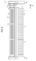
Fig. 6 is a top view of the liquid ejecting section and the wiping apparatus when the protective member is wiped. -
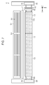
Fig. 7 is a top view of a protective member and a wiping apparatus when a liquid ejecting section is wiped. -
Fig. 8 is a schematic view showing a modified example of the liquid ejecting apparatus. -
Fig. 9 is a schematic view showing a modified example of the protective member and a movement mechanism. - Embodiments of a liquid ejecting apparatus will now be described by way of example only with reference to the accompanying drawings.
- As shown in
Fig. 1 , a liquid ejectingapparatus 11 includes a liquid ejectingsection 13 in which a plurality ofnozzles 12 that can eject liquid droplets are opened, asupply path 15 to supply liquid of aliquid supply source 14 to theliquid ejecting section 13, a pressure adjusting mechanism 16 that adjusts the pressure of liquid in theliquid ejecting section 13, and awiping apparatus 41. The liquid ejectingapparatus 11 also includes aprotective member 51 that is disposed between a medium S and the liquid ejectingsection 13 when the liquid ejectingsection 13 ejects liquid droplets onto the medium S in an ejecting direction Z, and acontrol section 100 that controls the liquid ejectingsection 13 and the like. - The liquid ejecting
apparatus 11 according to this embodiment is an ink jet printer that performs recording (printing) by ejecting liquid (one example is ink) from the liquid ejectingsection 13 onto a medium S, such as paper, to be transported in a transport direction Y which intersects (in this embodiment, is orthogonal to) the ejecting direction Z. The position in a direction intersecting the ejecting direction Z at which the liquid ejectingsection 13 ejects liquid droplets onto the medium S is referred to as a recording position. - The
liquid ejecting apparatus 11 has aline head 17 that includes, as a component, a plurality of liquid ejectingsections 13. These are arranged in a row to enable a print range in a width direction X, which intersects (in this embodiment, is orthogonal to) the transport direction Y and the ejecting direction Z, to span the entire width of the medium S. Theline head 17 has aliquid path 18 to supply liquid to theliquid ejecting section 13. The pressure adjusting mechanism 16 is provided at a midpoint on theliquid path 18. - At least one
liquid supply source 14 is provided. However, a plurality of (in this embodiment, four) liquid supply sources can also be provided; each liquid type (for example, each ink color) corresponds to one liquid supply source. When a plurality ofliquid ejecting sections 13 are provided, thesupply path 15 branches into a plurality of paths at a downstream side; each branched downstream end, which corresponds to eachliquid ejecting section 13, is connected to theliquid path 18 provided on theline head 17. Theliquid path 18 and the pressure adjusting mechanism 16 are provided for each liquid type on eachliquid ejecting section 13. - The pressure adjusting mechanism 16 includes a pressure chamber 21 provided at a midpoint on the
liquid path 18, a one-way valve 22 provided on an upstream side of the pressure chamber 21, anair chamber 24 partitioned by the pressure chamber 21 and aflexible film 23, a vent path 25 communicatively connected to theair chamber 24, a pump 26 provided at a midpoint on the vent path 25, and an on-offvalve 27 provided on an end of the vent path 25. The one-way valve 22 allows flow of liquid from theliquid supply source 14 on the upstream side to theliquid ejecting section 13 on the downstream side, whereas the valve checks backflow of liquid from the downstream side to the upstream side. When the on-offvalve 27 is opened with the pump 26 not driven, the vent path 25 and theair chamber 24 are communicatively connected to the atmosphere. - When the
flexible film 23 is displaced flexibly, as shown by the solid line inFig. 1 , in a direction in which theair chamber 24 narrows, the pressure adjusting mechanism 16 displaces theflexible film 23 flexibly toward the pressure chamber 21, as shown by the dash-double-dot line inFig. 1 , by driving the pump 26 to introduce gas into theair chamber 24. Then, liquid in the pressure chamber 21 flows toward theliquid ejecting section 13 on the downstream side, and liquid in eachnozzle 12 is pressurized. In other words, the pressure adjusting mechanism 16 functions as a pressurizing mechanism that pressurizes liquid in theliquid path 18. - In the pressure adjusting mechanism 16, the
flexible film 23 may be displaced flexibly toward the pressure chamber 21 by pressing theflexible film 23 with a biasing member, such as a piston, a spring, or the like, which is disposed in theair chamber 24, instead of introducing gas with the pump 26 to displace theflexible film 23. That is to say, an arrangement that displaces theflexible film 23 may be optionally changed. - The one-
way valve 22 is opened when a pressure in theliquid path 18 at a downstream side below the pressure chamber 21 is less than a default value, which is less than atmospheric pressure, whereas the valve may be configured as a differential pressure regulating valve (a self-sealing valve) to remain closed when the pressure in theliquid path 18 at the downstream side below the pressure chamber 21 is greater than or equal to the default value. According to this configuration, the pressure in theliquid path 18 at the downstream side below the pressure chamber 21 can be maintained at a negative pressure on the order of the default value by a pressure adjusting feature of the pressure adjusting mechanism 16. Thus, as a result of the negative pressure, a uniform meniscus (a curved concave liquid surface) is formed in eachnozzle 12. This can increase accuracy of liquid droplet ejection and can prevent liquid leakage from eachnozzle 12 due to vibration or the like. In this case, a biasing member, for example, a spring, that biases theflexible film 23 toward theair chamber 24 is installed in the pressure chamber 21 to keep the pressure chamber 21 at a negative pressure. In addition, the on-offvalve 27 is opened to expose theair chamber 24 to the atmosphere, and the differential pressure regulating valve may be opened depending on a difference between a pressure (atmospheric pressure) in theair chamber 24 and a pressure of liquid in the pressure chamber 21. - The
liquid ejecting section 13 includes acommon liquid chamber 31 that temporarily stores liquid to be supplied through theliquid path 18 provided for each liquid type, a plurality ofcavities 32 provided correspondingly for a plurality of thenozzles 12, and a plurality ofactuators 33 provided correspondingly for thecavities 32. Theactuators 33 are, for example, piezoelectric elements that contract and deform when energized. After the volume of eachcavity 32 is increased by driving (energizing) eachactuator 33, when energization is stopped, eachcavity 32 is restored and deforms but decreases its volume by this restore-deform reaction. Then, liquid flows out into eachnozzle 12 from eachcavity 32 of which volume has been decreased, and the liquid is ejected from eachnozzle 12 as a liquid droplet. - The
liquid ejecting section 13 has a plurality of nozzle groups N for ejecting a plurality of types of liquid from theliquid ejecting section 13. Each nozzle group corresponds to each liquid type and is composed of a plurality ofnozzles 12 that eject one type of liquid. Each nozzle group N is a group of thenozzles 12 to which liquid is supplied from onecommon liquid chamber 31. Each nozzle group N can be, for example, one or more nozzle rows composed of thenozzles 12 arrayed in the width direction X. - The wiping
apparatus 41 includes a wipingmember 42 that wipes theliquid ejecting section 13 and theprotective member 51, a retainingmember 43 that retains the wipingmember 42,guidance shafts 44 that guide the retainingmember 43 in the width direction X, asupport mechanism 45 that supports theguidance shafts 44, and amovement apparatus 46 that moves thesupport mechanism 45 in the transport direction Y. Preferably, thesupport mechanism 45 is configured so that the position of the wipingmember 42 can be changed in the ejecting direction Z by moving theguidance shafts 44 in the ejecting direction Z. The wipingmember 42 may be, for example, a plate member made of an elastically deformable resin or may be an absorbing member, such as a cloth, that can absorb liquid. - When the
liquid ejecting section 13 ejects a liquid droplet of a designated size, a minute string like liquid droplet occurs between the liquid droplet of the target size and eachnozzle 12. This minute liquid droplet floats around in the form of a mist, attaching to anaperture surface 19a or the like. When the amount of liquid attached to theaperture surface 19a increases, the liquid may fall onto the medium S, or a raised medium S may come into contact with the liquid, causing the medium S to be contaminated. - Furthermore, when liquid attached to the
aperture surface 19a gathers around eachnozzle 12, a liquid droplet which has been ejected from eachnozzle 12 may come into contact with that gathered liquid and change its trajectory. In addition, paper powder and dust dispersed in association with transport of a medium S made of paper may attach to theaperture surface 19a, become mixed with liquid and adhere thereto. - To address this issue, in the
liquid ejecting apparatus 11, after theliquid ejecting section 13 has ejected a designated amount of liquid (droplets), or after a designated number of copies have been printed, the wipingapparatus 41 wipes the liquid ejecting section 13 (wiping is performed) as maintenance to remove foreign materials, such as liquid and the like, attached to theaperture surface 19a. When wiping is performed, themovement apparatus 46 moves thesupport mechanism 45 to the recording position corresponding to theliquid ejecting section 13 in the transport direction Y and moves the wipingmember 42 together with the retainingmember 43 along theguidance shafts 44 in the width direction X. - Before wiping, by adjusting the position of the
guidance shafts 44 in the ejecting direction Z, thesupport mechanism 45 adjusts the contact pressure of the wipingmember 42 on theliquid ejecting section 13. Wiping can be performed by the wipingmember 42 reciprocating in the width direction X once or multiple times, or can be performed by the wipingmember 42 moving forward only or moving backward only. - In this wiping, the
movement apparatus 46 may move the wipingmember 42 to the recording position as in this embodiment, or theline head 17 may be moved from the recording position to a movement area of the wiping member 42 (for example, an area upstream from the recording position in the transport direction Y). - As shown in
Fig. 2 , theliquid ejecting section 13 includes anozzle plate 19 through which thenozzles 12 are formed and a fixedframe 20 that holds thenozzle plate 19. In this embodiment, an opening for eachnozzle 12 that ejects liquid droplets is anejection outlet 12a; in theliquid ejecting section 13, an outer (bottom) surface of thenozzle plate 19 having theejection outlet 12a open thereon is theaperture surface 19a. On theaperture surface 19a, a liquid-repellent film is provided to appropriately form a meniscus (a liquid surface M, which is curved and concave in response to surface tension) on theejection outlet 12a or to prevent contaminated attachments. - On the
aperture surface 19a of theliquid ejecting section 13, theejection outlets 12a in the nozzle row (which eject the same kind of liquid) are arrayed in a row in the width direction of the medium S (in a row direction in which theliquid ejecting sections 13 are arrayed). Also, on theaperture surface 19a of theliquid ejecting section 13, a plurality of (for example, four)ejection outlets 12a (which eject a different kind of liquid), that is, the nozzle rows, are arrayed in a line in the transport direction Y. The fixedframe 20 is provided with a plurality of (in this embodiment, four)aperture portions 20a; each nozzle row or each nozzle group has an aperture portion in order to expose theaperture surface 19a. - During wiping of the
liquid ejecting section 13, the fixedframe 20 and theaperture surface 19a are wiped. Repetitive wiping of theaperture surface 19a, however, may damage the liquid-repellent film. This may cause decreased accuracy of liquid droplet ejection or cause foreign materials to attach easily to the surface. In this embodiment, in order to prevent foreign material such as mist from attaching to theaperture surface 19a, theprotective member 51 is disposed between the medium S and theaperture surface 19a when theliquid ejecting section 13 ejects liquid droplets. - The
protective member 51 haspassage openings 52 which enable liquid droplets Dr that theliquid ejecting section 13 ejects from theejection outlets 12a to pass, and the protective member is disposed between the medium S and theaperture surface 19a at least when theliquid ejecting section 13 ejects the liquid droplets Dr onto the medium S. Thepassage openings 52 of theprotective member 51 are provided in correspondence with one or more of theejection outlets 12a. - On the
protective member 51 in this embodiment, each passage opening 52 is formed so as to correspond to a respective one of each nozzle row or each nozzle group in the width direction X, which is a longitudinal direction (see alsoFigs. 6 and7 ). Each passage opening 52 may be a notch extending from an end of theprotective member 51, instead of a through hole provided on theprotective member 51, which is a plate-type. It is preferred, however, that thepassage openings 52 have a small opening area so that exposure area of theaperture surface 19a is as small as possible, while securing the opening area that enables the liquid droplets Dr to pass. Preferably, the opening area of each passage opening 52 is smaller than the opening area of eachaperture portion 20a in the fixedframe 20, for example. - When the
liquid ejecting section 13 ejects the liquid droplets Dr onto the medium S, theprotective member 51 is disposed so that theejection outlets 12a and thepassage openings 52 align in the ejecting direction Z. The position of theprotective member 51 in this case (the position shown inFig. 2 ) is referred to as the protection position. - A
support member 55 to support the medium S is disposed at the recording position when theliquid ejecting section 13 ejects the liquid droplets Dr onto the medium S. Thus, may be said that theprotective member 51 is disposed between thesupport member 55 and theaperture surface 19a when theliquid ejecting section 13 ejects the liquid droplets Dr onto the medium S. In embodiments where wiping is performed at the recording position, thesupport member 55 may be configured to be capable of retracting from the recording position to a different position during wiping. - Preferably, the
protective member 51 is disposed at a position spaced from both the medium S and theaperture surface 19a in the ejecting direction Z and also at a position which is nearer to theaperture surface 19a than to the medium S when the liquid droplets Dr are ejected onto the medium S. - In this embodiment, the
protective member 51 has aprotection surface 53 that faces theaperture surface 19a at a distance to theaperture surface 19a when the protective member is disposed between the medium S and theaperture surface 19a, and anacceptance surface 54 opposite to theprotection surface 53. Theprotection surface 53 and theacceptance surface 54 may not necessarily be flat surfaces; for example, they may have grooves and asperities to retain liquid. - It is preferable that the
protective member 51, when disposed spaced from theaperture surface 19a of theliquid ejecting section 13, be subject to surface treatment so that itsacceptance surface 54, which is a portion of theprotective member 51 facing the medium S, is more liquid-repellent than itsprotection surface 53, which is a portion facing theliquid ejecting section 13. When there is a distance between theprotective member 51 and theaperture surface 19a or the medium S, mist occurring during ejection of the liquid droplets Dr attaches to theprotection surface 53 or theacceptance surface 54 of theprotective member 51. If theacceptance surface 54 has a higher liquid-repellency, however, liquid attached to theacceptance surface 54 moves easily to theprotection surface 53 through thepassage openings 52 and the like. As a result, it is less likely that liquid will gather on theacceptance surface 54 or that the liquid attached to theacceptance surface 54 will cause the medium S to be contaminated. - Preferably, the
liquid ejecting apparatus 11 is provided with amovement mechanism 50 that moves theprotective member 51. Theprotective member 51 may be moved by themovement mechanism 50 in the ejecting direction Z so that the distance to theaperture surface 19a can be changed. Alternatively and/or additionally, theprotective member 51 may be moved by themovement mechanism 50 in the transport direction Y or the width direction X. Such configurations enable theprotective member 51 to move in the ejecting direction Z depending on the thickness of the medium S and enable theprotective member 51 to retract from the recording position. - The relative position of the
protective member 51 to theliquid ejecting section 13 may also be changed by moving theliquid ejecting section 13. When theliquid ejecting section 13 is configured to be movable, it is possible to adjust the contact pressure during wiping by moving theliquid ejecting section 13 instead of moving the wipingmember 42 in the ejecting direction Z. - When the
protective member 51 and theliquid ejecting section 13 move relative to each other, theprotective member 51 and theliquid ejecting section 13 may move while in contact with each other. Preferably, theprotective member 51 and theliquid ejecting section 13 move while not in contact with each other, however. When theprotective member 51 moves in contact with theliquid ejecting section 13, theliquid ejecting section 13 may be damaged by theprotective member 51 sliding, or foreign material may become stuck between theprotective member 51 and theliquid ejecting section 13. If the fixedframe 20 holding thenozzle plate 19 is thinner than a foreign material, when theprotective member 51 slides, the foreign material attached to theprotective member 51 or theliquid ejecting section 13 may be dragged in contact with theaperture surface 19a. This may damage theaperture surface 19a. - As shown in
Fig. 3 , when theliquid ejecting section 13 is not ejecting liquid droplets, theprotective member 51 may be moved to a closed position (the position shown inFig. 3 ). At this position, theprotection surface 53 at which thepassage openings 52 of theprotective member 51 are not formed faces theejection outlets 12a and is in contact with the fixedframe 20 of theliquid ejecting section 13. Thus, theprotective member 51 is disposed at the closed position which covers theejection outlets 12a of theliquid ejecting section 13. Drying of thenozzles 12 can therefore be prevented when theliquid ejecting section 13 is not ejecting liquid droplets. This will avoid clogging of thenozzles 12 caused by drying of thenozzles 12 or poor ejection caused by, for example, increased viscosity of liquid in thenozzles 12. - Or, as shown in
Fig. 4 , when theliquid ejecting section 13 is not ejecting liquid droplets, theprotective member 51 may be disposed at a facing position (the position shown inFig. 4 ). At this position, theprotection surface 53 at which thepassage openings 52 of theprotective member 51 are not formed faces theejection outlets 12a and is near but not in contact with the fixedframe 20 of theliquid ejecting section 13. - When the
protective member 51 is disposed at the facing position, a pressurizing feature of the pressure adjusting mechanism 16 (seeFig. 1 ) pressurizes liquid in theliquid path 18 that supplies liquid to theejection outlets 12a, and forces out the liquid surface M, which is concave, from theejection outlets 12a. The forced out liquid then attaches to theprotection surface 53 and seals a gap between theejection outlets 12a and theprotection surface 53 with liquid, thereby preventing drying of thenozzles 12. - When the
liquid ejecting apparatus 11 is not provided with the pressure adjusting mechanism 16 (the pressurizing mechanism), the gap between theejection outlets 12a and theprotection surface 53 may be sealed with the liquid droplets that have been ejected by theliquid ejecting section 13 onto theprotection surface 53 of theprotective member 51 located at the facing position. However, it is preferable to force out the liquid surface from theejection outlets 12a and attach the forced out liquid to theprotection surface 53. This can prevent bubbles from mixing into thenozzles 12 when theejection outlets 12a are sealed with theprotection surface 53 and liquid. - In such cases where liquid is allowed to attach to the
protection surface 53, theprotective member 51 may have a liquid-repellent film on theprotection surface 53. This prevents liquid from adhering to theprotection surface 53 of theprotective member 51. When theliquid ejecting section 13 ejects a plurality of types of liquid, theprotection surface 53 repels attached liquid. This can prevent mixing of different liquids on theprotection surface 53 and mixing of a different type of liquid, instead of liquid to be ejected, into thenozzles 12. - Protection against drying of the
nozzles 12 by using theprotective member 51 is especially effective in cases where liquid droplets are not ejected for an extended period of time, for example, when theliquid ejecting apparatus 11 is turned off. If theprotective member 51 can be used to protect against drying of thenozzles 12, a cap or the like to cover eachnozzle 12 does not need to be provided for this protection purpose. - Preferably, as shown in
Fig. 5 , by use of themovement mechanism 50, theprotective member 51 is capable of moving relative to theliquid ejecting section 13 between the protection position (shown by the dash-double-dot line inFig. 5 ) and a retracted position (shown by the solid line inFig. 5 ) which is distant from theliquid ejecting section 13 compared to the protection position. The protection position is a position which faces theaperture surface 19a in such a manner that theejection outlets 12a and thepassage openings 52 align in the ejecting direction Z for liquid droplets. - Since the protection position is also the recording position, a position to which the
protective member 51 is moved from the protection position in the transport direction Y, for example, is the retracted position. By enabling themovement apparatus 46 to move the wipingmember 42 from the recording position in the transport direction Y, wiping of theprotective member 51 can be performed at the retracted position by the wipingmember 42. - That is, after the
movement apparatus 46 moves thesupport mechanism 45 to a position corresponding to theprotective member 51 located at the retracted position, foreign material such as liquid attached to theacceptance surface 54 is wiped by moving the wipingmember 42 together with the retainingmember 43 along theguidance shafts 44 in the width direction X. Wiping of theprotective member 51 can be performed by the wipingmember 42 moving in a reciprocating manner once or multiple times, or can be performed by the wipingmember 42 moving forward or backward. - In addition to the wiping
member 42 that can wipe theacceptance surface 54 of theprotective member 51 at the retracted position, the wipingapparatus 41 may also include a cleaningmember 47 that cleans theprotection surface 53 of theprotective member 51. As in the wipingmember 42, the cleaningmember 47 may be a plate member made of an elastically deformable resin or may be an absorbing member, such as a cloth, a porous member, or the like, that can absorb liquid. Again, as in the wipingmember 42, the cleaningmember 47 may wipe theprotection surface 53 of theprotective member 51 while moving at the retracted position in the width direction X. - Or, as shown in
Fig. 5 , the cleaningmember 47 may be disposed on a path (shown by the dash-dot line inFig. 5 ) on which theprotective member 51 moves from the protection position to the retracted position so that, in a process of theprotective member 51 moving between the protection position and the retracted position, the cleaningmember 47 performs cleaning (wiping) while in sliding contact with theprotection surface 53. - As shown in
Fig. 6 , by moving theprotective member 51 from the protection position (the recording position) to the retracted position at some midpoint during execution of recording onto the medium S by theliquid ejecting section 13, cleaning of theprotection surface 53 may be done by the cleaningmember 47 and wiping of theacceptance surface 54 may be done by the wipingmember 42. This enables maintenance to be performed during execution of recording even when large amounts of mist occur with continuous recording done by theliquid ejecting section 13. This maintenance involves allowing the mist to attach to theprotective member 51 and removing the mist by the cleaningmember 47 and the wipingmember 42. Therefore, in order to perform wiping of theliquid ejecting section 13, no interrupting of recording is needed. - Even when the
liquid ejecting section 13 is protected with theprotective member 51 to prevent mist from attaching thereto, if there is a gap between theprotective member 51 and theliquid ejecting section 13, mist and the like may attach to theliquid ejecting section 13. Thus, theliquid ejecting section 13 may be wiped by the wipingmember 42 in cases such as when recording ends, when the number of copies or the number of times a liquid droplet is ejected, which is set for each ejecting mode with liquid droplets of a different size, exceeds a threshold value at the time of recording, and when periodic maintenance is performed. When thecontrol section 100 has a counter that counts the number of copies or the number of times a liquid droplet is ejected and controls a count value for comparison with the threshold value, the count value of the counter may be reset each time wiping is made by the wipingmember 42. - During wiping of the
liquid ejecting section 13, as shown inFig. 7 , theliquid ejecting section 13 may be wiped by moving theprotective member 51 to the retracted position and moving the wipingmember 42 to a position corresponding to the recording position. The contact pressure of the wipingmember 42 can be set appropriately by thesupport mechanism 45, which adjusts the position of the wipingmember 42 in the ejecting direction Z, for both wiping of theprotective member 51 and wiping of theliquid ejecting section 13. - Next, operations of the
liquid ejecting apparatus 11 configured as shown above will be described. - In this embodiment, the
liquid ejecting apparatus 11, which includes theprotective member 51, can prevent foreign material such as mist from attaching to theliquid ejecting section 13. This can reduce the frequency of wiping theliquid ejecting section 13. Thus, the load of wiping on the liquid-repellent film of theaperture surface 19a can be decreased. - Also, by wiping (cleaning) the
protective member 51 which, instead of theliquid ejecting section 13, accepts mist and the like, the wipingapparatus 41 can prevent foreign material attached to theprotective member 51 from contaminating the medium S. When theliquid ejecting section 13 is not ejecting liquid droplets, drying of thenozzles 12 can be prevented by bringing theprotection surface 53 of theprotective member 51 into contact with theliquid ejecting section 13 in order to cover theejection outlets 12a of theliquid ejecting section 13 or by sealing theejection outlets 12a with theprotective member 51 and liquid. - In this way, depending on whether or not to eject liquid droplets or whether to wipe the
liquid ejecting section 13 or theprotective member 51, theprotective member 51 can be moved to a different position. By relatively moving the member apart from theliquid ejecting section 13, however, it is possible to decrease the load on the liquid-repellent film of theaperture surface 19a. - The embodiments described above have the following advantages.
- (1) Since the
protective member 51 is disposed between the medium S and theaperture surface 19a when theliquid ejecting section 13 ejects the liquid droplets Dr onto the medium S, foreign material such as mist occurring in association with ejection of the liquid droplets Dr becomes attached to theprotective member 51 before attaching to theaperture surface 19a. This can prevent the foreign material from attaching to theaperture surface 19a having theejection outlets 12a for the liquid droplets Dr open thereon. - (2) Mist and the like occurring in association with ejection of the liquid droplets Dr become attached to the
protective member 51 disposed between theliquid ejecting section 13 and the medium S. These foreign materials attached to theprotective member 51 can be removed by the wipingmember 42, which wipes theprotective member 51 at the retracted position. By wiping theprotective member 51, which accepts mist and the like instead of theaperture surface 19a, the frequency with which theaperture surface 19a is wiped can be reduced. The load of wiping on theaperture surface 19a can thus be decreased. - (3) The
protective member 51 is configured so as to be more liquid-repellent on the portion facing the medium S than on a portion facing theaperture surface 19a. In this case, even when mist occurring in association with ejection of the liquid droplets Dr becomes attached to the portion of theprotective member 51 facing the medium S, the liquid can be moved to the portion of theprotective member 51 facing theaperture surface 19a through thepassage openings 52 and the like. This can prevent the medium S from being contaminated with liquid attached to the portion of theprotective member 51 facing the medium S (the acceptance surface 54). - (4) The cleaning
member 47 cleans theprotection surface 53 of theprotective member 51. This can prevent foreign material attached to theprotection surface 53 from attaching to theaperture surface 19a. - (5) When the
liquid ejecting section 13 is not ejecting the liquid droplets Dr, theprotective member 51 is disposed at the closed position to cover theejection outlets 12a. This can prevent drying of theejection outlets 12a. - (6) Liquid is forced out from the
ejection outlets 12a when theprotective member 51 is disposed at the facing position; the forced out liquid attaches to theprotection surface 53. A gap between theejection outlets 12a and theprotection surface 53 can be sealed with liquid to prevent drying of theejection outlets 12a. - (7) When the
protection surface 53 of theprotective member 51 has a liquid-repellent film, even the liquid which is attached to theprotection surface 53 can be prevented from adhering to theprotection surface 53. When theliquid ejecting section 13 ejects a plurality of types of liquid, theprotection surface 53 repels attached liquid. This can prevent mixing of different liquids on theprotection surface 53 and mixing of a different type of liquid, instead of liquid to be ejected, into thenozzles 12. - The embodiments described above may for example and without limitation be modified as shown in the following examples. When practiced, the invention may for example be implemented with these modified examples combined with the embodiments.
- · Aside from the wiping apparatus that performs wiping of the
liquid ejecting section 13, a wiping apparatus that performs wiping or cleaning of theprotective member 51 may be provided. - · The
liquid ejecting apparatus 11 is not limited to a type having a line head of which the print range spans the entire width of the medium S. - For example, as shown in
Fig. 8 , this may be a serial type apparatus that alternates between ejection of liquid, which is carried out while acarriage 56 that retains theliquid ejecting section 13 is moving along aguide shaft 57 in the width direction X, and transport of the medium S in the transport direction Y. In this case, as shown by the dash-double-dot line inFig. 8 , amovement mechanism 50 may be provided that moves theprotective member 51 in the width direction X, matched with movement of acarriage 56, during ejection of liquid, or aprotective member 51 may be disposed that spans the entire width of the print range. - · As shown in
Fig. 8 , the cleaningmember 47 may be configured to be retained with a retainingmember 48 similar to the one in the wipingmember 42; the cleaningmember 47 and the wipingmember 42, which extend in a direction (the transport direction Y) intersecting a wipe direction (the width direction X), may be disposed facing each other and arrayed in the ejecting direction Z. In this case, by allowing theprotective member 51 to move in the width direction X and to pass between the cleaningmember 47 and the wipingmember 42, as shown by the solid line inFig. 8 , simultaneous wiping of theprotection surface 53 and theacceptance surface 54 is possible. - · As shown in
Fig. 9 , theprotective member 51 may be a sheet-type. In this case, themovement mechanism 50 that moves theprotective member 51 relative to theliquid ejecting section 13 can be configured with a roller 50F that feeds out at designated intervals the sheet-typeprotective member 51 on which thepassage openings 52 are arrayed, and a roller 50S that takes up theprotective member 51. This configuration needs no wiping apparatus that performs wiping or cleaning of theprotective member 51 since a contaminated portion only has to be taken up onto the roller 50S by rotating the rollers 50F, 50S when theprotective member 51 is contaminated due to mist or the like. - In this configuration, when wiping of the
liquid ejecting section 13 is done, theprotective member 51 may be retracted to a position distant from theliquid ejecting section 13. Alternatively, at a designated position of the sheet-typeprotective member 51, an opening for wiping may be provided that is large enough to expose theaperture surface 19a entirely. By rotating the rollers 50F, 50S, the opening for wiping is disposed to align with theaperture surface 19a in the ejecting direction Z, and after that, wiping of theliquid ejecting section 13 may be performed through the opening for wiping. - · The
liquid ejecting apparatus 11 may be provided with a circulating path that circulates liquid between thesupply path 15 and theliquid path 18, and a circulating pump that circulates liquid on the circulating path. This configuration is desirable because it can avoid sedimentation of components in response to circulation when liquid containing components having a sedimentation property is used, for example, in such a case where liquid ink is a pigment ink containing pigments. Even when liquid does not contain such components, it is preferable that a bubble trap be provided at a midpoint on the path to circulate liquid. This can collect bubbles with liquid circulation. When this circulating pump is provided, the circulating pump may function as a pressurizing mechanism to force out the liquid surface M from theejection outlets 12a. Namely, liquid in theliquid path 18 may be pressurized by driving the circulating pump to circulate liquid. - · When the
liquid ejecting apparatus 11 includes a pressurizing mechanism, wiping may be performed with the liquid surface M forced out from theejection outlets 12a by means of pressurization. In this case, the wipingmember 42 will not push foreign material, such as bubbles, into thenozzles 12 during wiping. Again, when theliquid ejecting apparatus 11 includes the pressurizing mechanism, pressurized cleaning may be performed at a designated timing. This pressurized cleaning involves discharging liquid from thenozzles 12 by pressurization. In this case, pressurized cleaning can discharge foreign material, such as bubbles, which are mixed into theliquid ejecting section 13. In this way, the pressurizing mechanism can be used for multiple purposes to do a wide range of maintenance operations while preventing an increase in the complexity of units. - · In contrast with print operations, as a maintenance operation to remove foreign material, such as bubbles, which are mixed into the
nozzles 12, flushing may be performed in which liquid droplets are flushed out from thenozzles 12. In this case, a separate flushing box may be provided to accept flushed out, or discharged, liquid droplets. Alternatively, theprotection surface 53 of theprotective member 51 may accept these flushed out liquid droplets. When the flushed out liquid droplets are accepted by theprotective member 51, it is preferable that the distance between theprotection surface 53 and theaperture surface 19a in the ejecting direction Z be longer than the distance during printing to prevent liquid accepted by theprotection surface 53 from attaching to theaperture surface 19a. - · Liquid that the liquid ejecting section ejects is not limited to ink, and may be, for example, a liquid material in which particles in a functional material are dispersed or mixed into a liquid. The invention may be configured to perform recording by ejecting a liquid material containing a dispersed or dissolved material, such as an electrode material or a coloring material (a pixel material), used to manufacture a liquid crystal display, an electroluminescent display, or a surface emitting display, for example.
- · The medium is not limited to paper, and may be a thin plate member, a plastic film or the like, or may be a fabric used for a textile printing unit or the like. Moreover, the medium is not limited to a sheet- or plate-type, and may be clothes, such as T-shirts, for example, or three-dimensional objects such as tableware and stationery.
- The entire disclosure of
Japanese Patent Application No. 2015-178235, filed September 10, 2015 - The foregoing description has been given by way of example only and it will be appreciated by a person skilled in the art that modifications can be made without departing from the scope of the present invention as defined by the claims.
Claims (7)
- A liquid ejecting apparatus (11) comprising:a liquid ejecting section (13) with an aperture surface (19a) having ejection outlets (12a) that eject liquid droplets; anda protective member (51) having passage openings (52) that enable the liquid droplets to pass, the protective member being disposed between a medium (S) and the aperture surface when the liquid ejecting section ejects liquid droplets onto the medium.
- The liquid ejecting apparatus according to claim 1, further comprising a wiping member (42) capable of wiping the protective member at a retracted position, wherein the protective member is capable of moving relative to the liquid ejecting section between a protection position and the retracted position that is distant from the liquid ejecting section compared to the protection position, the protection position being a position that faces the aperture surface in such a manner that the ejection outlets and the passage openings align in a liquid droplet ejecting direction.
- The liquid ejecting apparatus according to claim 1 or claim 2, wherein the protective member is disposed spaced from the aperture surface and the protective member is more liquid-repellent on a portion (54) facing the medium than on a portion (53) facing the liquid ejecting section.
- The liquid ejecting apparatus according to any one of the preceding claims, further comprising a cleaning member (47) arranged to clean a protection surface (53) of the protective member, wherein the protection surface faces the aperture surface at a distance to the aperture surface when the protective member is disposed between the medium and the aperture surface.
- The liquid ejecting apparatus according to any one of the preceding claims, wherein the protective member is disposed at a closed position to cover the ejection outlets when the liquid ejecting section is not ejecting liquid droplets.
- The liquid ejecting apparatus according to any one of the preceding claims, further comprising a pressurizing mechanism (16) that, when the protective member is disposed at a facing position, pressurizes liquid in a liquid path to force out a liquid surface from the ejection outlets, wherein the liquid ejecting section includes the liquid path that supplies liquid to the ejection outlets; the protective member has a protection surface (53) that faces the aperture surface at a distance to the aperture surface when the protective member is disposed between the medium and the aperture surface, the protection surface being disposed at a facing position that faces the ejection outlets when the liquid ejecting section is not ejecting liquid droplets.
- The liquid ejecting apparatus according to claim 6, wherein the protection surface of the protective member includes a liquid-repellent film.
Applications Claiming Priority (1)
| Application Number | Priority Date | Filing Date | Title |
|---|---|---|---|
| JP2015178235A JP6606934B2 (en) | 2015-09-10 | 2015-09-10 | Liquid ejector |
Publications (2)
| Publication Number | Publication Date |
|---|---|
| EP3141390A1 true EP3141390A1 (en) | 2017-03-15 |
| EP3141390B1 EP3141390B1 (en) | 2019-12-11 |
Family
ID=56883713
Family Applications (1)
| Application Number | Title | Priority Date | Filing Date |
|---|---|---|---|
| EP16187617.2A Active EP3141390B1 (en) | 2015-09-10 | 2016-09-07 | Liquid ejecting apparatus |
Country Status (3)
| Country | Link |
|---|---|
| US (1) | US10022970B2 (en) |
| EP (1) | EP3141390B1 (en) |
| JP (1) | JP6606934B2 (en) |
Families Citing this family (2)
| Publication number | Priority date | Publication date | Assignee | Title |
|---|---|---|---|---|
| CN107160679B (en) * | 2016-03-08 | 2020-04-07 | 三纬国际立体列印科技股份有限公司 | Three-dimensional printer |
| CN115920715B (en) * | 2022-12-01 | 2024-04-26 | 淄博金箭医疗器械有限公司 | Be used for scope bedside enzyme liquid auto configuration conveying system |
Citations (4)
| Publication number | Priority date | Publication date | Assignee | Title |
|---|---|---|---|---|
| JP2007276394A (en) | 2006-04-11 | 2007-10-25 | Fuji Xerox Co Ltd | Shutter apparatus and liquid droplet delivering apparatus equipped with this shutter apparatus |
| JP2011168032A (en) * | 2010-02-22 | 2011-09-01 | Seiko Epson Corp | Liquid ejection head, liquid ejection head unit, and liquid ejector |
| US20120120150A1 (en) * | 2010-11-11 | 2012-05-17 | Seiko Epson Corporation | Liquid ejection device |
| WO2014069497A1 (en) * | 2012-11-01 | 2014-05-08 | セーレン株式会社 | Inkjet printing device |
Family Cites Families (7)
| Publication number | Priority date | Publication date | Assignee | Title |
|---|---|---|---|---|
| JPS62169654A (en) * | 1986-01-22 | 1987-07-25 | Fuji Xerox Co Ltd | Nozzle protector for continuous jet type ink jet printer |
| JP2746703B2 (en) * | 1989-11-09 | 1998-05-06 | 松下電器産業株式会社 | Ink jet head device and method of manufacturing the same |
| JP3554099B2 (en) * | 1996-02-13 | 2004-08-11 | キヤノン株式会社 | Inkjet printing equipment |
| US6412905B1 (en) * | 2000-12-21 | 2002-07-02 | Acer Communications And Multimedia | Ink jet cap with vent |
| JP2007283692A (en) | 2006-04-19 | 2007-11-01 | Seiko Epson Corp | Drawing device |
| JP2008260133A (en) | 2007-04-10 | 2008-10-30 | Fuji Xerox Co Ltd | Liquid droplet ejector |
| KR101305768B1 (en) * | 2011-12-27 | 2013-09-06 | 성균관대학교산학협력단 | Electrostatic spray printing apparatus |
-
2015
- 2015-09-10 JP JP2015178235A patent/JP6606934B2/en active Active
-
2016
- 2016-08-29 US US15/250,095 patent/US10022970B2/en active Active
- 2016-09-07 EP EP16187617.2A patent/EP3141390B1/en active Active
Patent Citations (4)
| Publication number | Priority date | Publication date | Assignee | Title |
|---|---|---|---|---|
| JP2007276394A (en) | 2006-04-11 | 2007-10-25 | Fuji Xerox Co Ltd | Shutter apparatus and liquid droplet delivering apparatus equipped with this shutter apparatus |
| JP2011168032A (en) * | 2010-02-22 | 2011-09-01 | Seiko Epson Corp | Liquid ejection head, liquid ejection head unit, and liquid ejector |
| US20120120150A1 (en) * | 2010-11-11 | 2012-05-17 | Seiko Epson Corporation | Liquid ejection device |
| WO2014069497A1 (en) * | 2012-11-01 | 2014-05-08 | セーレン株式会社 | Inkjet printing device |
Also Published As
| Publication number | Publication date |
|---|---|
| US20170072694A1 (en) | 2017-03-16 |
| US10022970B2 (en) | 2018-07-17 |
| EP3141390B1 (en) | 2019-12-11 |
| JP6606934B2 (en) | 2019-11-20 |
| JP2017052192A (en) | 2017-03-16 |
Similar Documents
| Publication | Publication Date | Title |
|---|---|---|
| US12070950B2 (en) | Liquid ejecting apparatus and cleaning device | |
| JP6477829B2 (en) | Cleaning method for fluid ejection device | |
| US10449767B2 (en) | Liquid ejecting apparatus and cleaning device | |
| US9994024B2 (en) | Liquid ejecting apparatus with movable head unit | |
| US20080246804A1 (en) | Liquid ejection head | |
| US9296210B2 (en) | Liquid ejecting apparatus | |
| JP5871860B2 (en) | RECOVERY MECHANISM OF RECORDING HEAD, INKJET RECORDING DEVICE EQUIPPED WITH THE RECOVERY MECHANISM, AND RECOVERY METHOD OF RECORDING HEAD | |
| US8622513B2 (en) | Using low pressure assist (LPA) to enable printhead maintenance system simplification | |
| US9545794B2 (en) | Selective purging of ink jets to limit purge mass | |
| US20180194141A1 (en) | Recording head and ink-jet recording apparatus provided with the same | |
| EP3141390B1 (en) | Liquid ejecting apparatus | |
| JP5509873B2 (en) | Liquid ejecting apparatus and method of recovering nozzle in liquid ejecting apparatus | |
| KR102080474B1 (en) | Printhead having apertures for application of a surface treatment fluid | |
| JP2017013301A (en) | Liquid ejecting apparatus and maintenance method | |
| US10336078B2 (en) | Recording head and inkjet recording apparatus including same | |
| JP5640544B2 (en) | Liquid ejecting apparatus and wiping method in liquid ejecting apparatus | |
| JP6221946B2 (en) | RECOVERY SYSTEM OF PRINT HEAD, INKJET RECORDING DEVICE EQUIPPED WITH THE SAME, AND RECOVERY METHOD OF RECORD HEAD | |
| US20240416656A1 (en) | Method for maintenance of a print head of an inkjet printer | |
| JP6950729B2 (en) | Liquid injection device and cleaning device | |
| JP2015091638A (en) | Recording-head recovery system, inkjet recording apparatus including the same, and recording-head recovery method | |
| JP2018111271A (en) | Recording head and ink-jet recording device having the same |
Legal Events
| Date | Code | Title | Description |
|---|---|---|---|
| PUAI | Public reference made under article 153(3) epc to a published international application that has entered the european phase |
Free format text: ORIGINAL CODE: 0009012 |
|
| STAA | Information on the status of an ep patent application or granted ep patent |
Free format text: STATUS: THE APPLICATION HAS BEEN PUBLISHED |
|
| AK | Designated contracting states |
Kind code of ref document: A1 Designated state(s): AL AT BE BG CH CY CZ DE DK EE ES FI FR GB GR HR HU IE IS IT LI LT LU LV MC MK MT NL NO PL PT RO RS SE SI SK SM TR |
|
| AX | Request for extension of the european patent |
Extension state: BA ME |
|
| STAA | Information on the status of an ep patent application or granted ep patent |
Free format text: STATUS: REQUEST FOR EXAMINATION WAS MADE |
|
| 17P | Request for examination filed |
Effective date: 20170915 |
|
| RBV | Designated contracting states (corrected) |
Designated state(s): AL AT BE BG CH CY CZ DE DK EE ES FI FR GB GR HR HU IE IS IT LI LT LU LV MC MK MT NL NO PL PT RO RS SE SI SK SM TR |
|
| GRAP | Despatch of communication of intention to grant a patent |
Free format text: ORIGINAL CODE: EPIDOSNIGR1 |
|
| STAA | Information on the status of an ep patent application or granted ep patent |
Free format text: STATUS: GRANT OF PATENT IS INTENDED |
|
| INTG | Intention to grant announced |
Effective date: 20190902 |
|
| GRAS | Grant fee paid |
Free format text: ORIGINAL CODE: EPIDOSNIGR3 |
|
| GRAA | (expected) grant |
Free format text: ORIGINAL CODE: 0009210 |
|
| STAA | Information on the status of an ep patent application or granted ep patent |
Free format text: STATUS: THE PATENT HAS BEEN GRANTED |
|
| AK | Designated contracting states |
Kind code of ref document: B1 Designated state(s): AL AT BE BG CH CY CZ DE DK EE ES FI FR GB GR HR HU IE IS IT LI LT LU LV MC MK MT NL NO PL PT RO RS SE SI SK SM TR |
|
| REG | Reference to a national code |
Ref country code: GB Ref legal event code: FG4D |
|
| REG | Reference to a national code |
Ref country code: CH Ref legal event code: EP |
|
| REG | Reference to a national code |
Ref country code: AT Ref legal event code: REF Ref document number: 1211793 Country of ref document: AT Kind code of ref document: T Effective date: 20191215 |
|
| REG | Reference to a national code |
Ref country code: DE Ref legal event code: R096 Ref document number: 602016025900 Country of ref document: DE |
|
| REG | Reference to a national code |
Ref country code: IE Ref legal event code: FG4D |
|
| REG | Reference to a national code |
Ref country code: NL Ref legal event code: MP Effective date: 20191211 |
|
| REG | Reference to a national code |
Ref country code: LT Ref legal event code: MG4D |
|
| PG25 | Lapsed in a contracting state [announced via postgrant information from national office to epo] |
Ref country code: FI Free format text: LAPSE BECAUSE OF FAILURE TO SUBMIT A TRANSLATION OF THE DESCRIPTION OR TO PAY THE FEE WITHIN THE PRESCRIBED TIME-LIMIT Effective date: 20191211 Ref country code: BG Free format text: LAPSE BECAUSE OF FAILURE TO SUBMIT A TRANSLATION OF THE DESCRIPTION OR TO PAY THE FEE WITHIN THE PRESCRIBED TIME-LIMIT Effective date: 20200311 Ref country code: GR Free format text: LAPSE BECAUSE OF FAILURE TO SUBMIT A TRANSLATION OF THE DESCRIPTION OR TO PAY THE FEE WITHIN THE PRESCRIBED TIME-LIMIT Effective date: 20200312 Ref country code: LV Free format text: LAPSE BECAUSE OF FAILURE TO SUBMIT A TRANSLATION OF THE DESCRIPTION OR TO PAY THE FEE WITHIN THE PRESCRIBED TIME-LIMIT Effective date: 20191211 Ref country code: NO Free format text: LAPSE BECAUSE OF FAILURE TO SUBMIT A TRANSLATION OF THE DESCRIPTION OR TO PAY THE FEE WITHIN THE PRESCRIBED TIME-LIMIT Effective date: 20200311 Ref country code: SE Free format text: LAPSE BECAUSE OF FAILURE TO SUBMIT A TRANSLATION OF THE DESCRIPTION OR TO PAY THE FEE WITHIN THE PRESCRIBED TIME-LIMIT Effective date: 20191211 Ref country code: LT Free format text: LAPSE BECAUSE OF FAILURE TO SUBMIT A TRANSLATION OF THE DESCRIPTION OR TO PAY THE FEE WITHIN THE PRESCRIBED TIME-LIMIT Effective date: 20191211 |
|
| PG25 | Lapsed in a contracting state [announced via postgrant information from national office to epo] |
Ref country code: RS Free format text: LAPSE BECAUSE OF FAILURE TO SUBMIT A TRANSLATION OF THE DESCRIPTION OR TO PAY THE FEE WITHIN THE PRESCRIBED TIME-LIMIT Effective date: 20191211 Ref country code: HR Free format text: LAPSE BECAUSE OF FAILURE TO SUBMIT A TRANSLATION OF THE DESCRIPTION OR TO PAY THE FEE WITHIN THE PRESCRIBED TIME-LIMIT Effective date: 20191211 |
|
| PG25 | Lapsed in a contracting state [announced via postgrant information from national office to epo] |
Ref country code: AL Free format text: LAPSE BECAUSE OF FAILURE TO SUBMIT A TRANSLATION OF THE DESCRIPTION OR TO PAY THE FEE WITHIN THE PRESCRIBED TIME-LIMIT Effective date: 20191211 |
|
| PG25 | Lapsed in a contracting state [announced via postgrant information from national office to epo] |
Ref country code: EE Free format text: LAPSE BECAUSE OF FAILURE TO SUBMIT A TRANSLATION OF THE DESCRIPTION OR TO PAY THE FEE WITHIN THE PRESCRIBED TIME-LIMIT Effective date: 20191211 Ref country code: PT Free format text: LAPSE BECAUSE OF FAILURE TO SUBMIT A TRANSLATION OF THE DESCRIPTION OR TO PAY THE FEE WITHIN THE PRESCRIBED TIME-LIMIT Effective date: 20200506 Ref country code: NL Free format text: LAPSE BECAUSE OF FAILURE TO SUBMIT A TRANSLATION OF THE DESCRIPTION OR TO PAY THE FEE WITHIN THE PRESCRIBED TIME-LIMIT Effective date: 20191211 Ref country code: CZ Free format text: LAPSE BECAUSE OF FAILURE TO SUBMIT A TRANSLATION OF THE DESCRIPTION OR TO PAY THE FEE WITHIN THE PRESCRIBED TIME-LIMIT Effective date: 20191211 Ref country code: RO Free format text: LAPSE BECAUSE OF FAILURE TO SUBMIT A TRANSLATION OF THE DESCRIPTION OR TO PAY THE FEE WITHIN THE PRESCRIBED TIME-LIMIT Effective date: 20191211 Ref country code: ES Free format text: LAPSE BECAUSE OF FAILURE TO SUBMIT A TRANSLATION OF THE DESCRIPTION OR TO PAY THE FEE WITHIN THE PRESCRIBED TIME-LIMIT Effective date: 20191211 |
|
| PG25 | Lapsed in a contracting state [announced via postgrant information from national office to epo] |
Ref country code: SM Free format text: LAPSE BECAUSE OF FAILURE TO SUBMIT A TRANSLATION OF THE DESCRIPTION OR TO PAY THE FEE WITHIN THE PRESCRIBED TIME-LIMIT Effective date: 20191211 Ref country code: SK Free format text: LAPSE BECAUSE OF FAILURE TO SUBMIT A TRANSLATION OF THE DESCRIPTION OR TO PAY THE FEE WITHIN THE PRESCRIBED TIME-LIMIT Effective date: 20191211 Ref country code: IS Free format text: LAPSE BECAUSE OF FAILURE TO SUBMIT A TRANSLATION OF THE DESCRIPTION OR TO PAY THE FEE WITHIN THE PRESCRIBED TIME-LIMIT Effective date: 20200411 |
|
| REG | Reference to a national code |
Ref country code: DE Ref legal event code: R097 Ref document number: 602016025900 Country of ref document: DE |
|
| REG | Reference to a national code |
Ref country code: AT Ref legal event code: MK05 Ref document number: 1211793 Country of ref document: AT Kind code of ref document: T Effective date: 20191211 |
|
| PLBE | No opposition filed within time limit |
Free format text: ORIGINAL CODE: 0009261 |
|
| STAA | Information on the status of an ep patent application or granted ep patent |
Free format text: STATUS: NO OPPOSITION FILED WITHIN TIME LIMIT |
|
| PG25 | Lapsed in a contracting state [announced via postgrant information from national office to epo] |
Ref country code: DK Free format text: LAPSE BECAUSE OF FAILURE TO SUBMIT A TRANSLATION OF THE DESCRIPTION OR TO PAY THE FEE WITHIN THE PRESCRIBED TIME-LIMIT Effective date: 20191211 |
|
| 26N | No opposition filed |
Effective date: 20200914 |
|
| PG25 | Lapsed in a contracting state [announced via postgrant information from national office to epo] |
Ref country code: AT Free format text: LAPSE BECAUSE OF FAILURE TO SUBMIT A TRANSLATION OF THE DESCRIPTION OR TO PAY THE FEE WITHIN THE PRESCRIBED TIME-LIMIT Effective date: 20191211 Ref country code: SI Free format text: LAPSE BECAUSE OF FAILURE TO SUBMIT A TRANSLATION OF THE DESCRIPTION OR TO PAY THE FEE WITHIN THE PRESCRIBED TIME-LIMIT Effective date: 20191211 |
|
| PG25 | Lapsed in a contracting state [announced via postgrant information from national office to epo] |
Ref country code: IT Free format text: LAPSE BECAUSE OF FAILURE TO SUBMIT A TRANSLATION OF THE DESCRIPTION OR TO PAY THE FEE WITHIN THE PRESCRIBED TIME-LIMIT Effective date: 20191211 |
|
| PG25 | Lapsed in a contracting state [announced via postgrant information from national office to epo] |
Ref country code: PL Free format text: LAPSE BECAUSE OF FAILURE TO SUBMIT A TRANSLATION OF THE DESCRIPTION OR TO PAY THE FEE WITHIN THE PRESCRIBED TIME-LIMIT Effective date: 20191211 |
|
| PG25 | Lapsed in a contracting state [announced via postgrant information from national office to epo] |
Ref country code: MC Free format text: LAPSE BECAUSE OF FAILURE TO SUBMIT A TRANSLATION OF THE DESCRIPTION OR TO PAY THE FEE WITHIN THE PRESCRIBED TIME-LIMIT Effective date: 20191211 |
|
| REG | Reference to a national code |
Ref country code: CH Ref legal event code: PL |
|
| REG | Reference to a national code |
Ref country code: BE Ref legal event code: MM Effective date: 20200930 |
|
| PG25 | Lapsed in a contracting state [announced via postgrant information from national office to epo] |
Ref country code: LU Free format text: LAPSE BECAUSE OF NON-PAYMENT OF DUE FEES Effective date: 20200907 |
|
| PG25 | Lapsed in a contracting state [announced via postgrant information from national office to epo] |
Ref country code: BE Free format text: LAPSE BECAUSE OF NON-PAYMENT OF DUE FEES Effective date: 20200930 Ref country code: CH Free format text: LAPSE BECAUSE OF NON-PAYMENT OF DUE FEES Effective date: 20200930 Ref country code: LI Free format text: LAPSE BECAUSE OF NON-PAYMENT OF DUE FEES Effective date: 20200930 Ref country code: IE Free format text: LAPSE BECAUSE OF NON-PAYMENT OF DUE FEES Effective date: 20200907 |
|
| PGFP | Annual fee paid to national office [announced via postgrant information from national office to epo] |
Ref country code: FR Payment date: 20210812 Year of fee payment: 6 |
|
| PGFP | Annual fee paid to national office [announced via postgrant information from national office to epo] |
Ref country code: DE Payment date: 20210727 Year of fee payment: 6 Ref country code: GB Payment date: 20210728 Year of fee payment: 6 |
|
| PG25 | Lapsed in a contracting state [announced via postgrant information from national office to epo] |
Ref country code: TR Free format text: LAPSE BECAUSE OF FAILURE TO SUBMIT A TRANSLATION OF THE DESCRIPTION OR TO PAY THE FEE WITHIN THE PRESCRIBED TIME-LIMIT Effective date: 20191211 Ref country code: MT Free format text: LAPSE BECAUSE OF FAILURE TO SUBMIT A TRANSLATION OF THE DESCRIPTION OR TO PAY THE FEE WITHIN THE PRESCRIBED TIME-LIMIT Effective date: 20191211 Ref country code: CY Free format text: LAPSE BECAUSE OF FAILURE TO SUBMIT A TRANSLATION OF THE DESCRIPTION OR TO PAY THE FEE WITHIN THE PRESCRIBED TIME-LIMIT Effective date: 20191211 |
|
| PG25 | Lapsed in a contracting state [announced via postgrant information from national office to epo] |
Ref country code: MK Free format text: LAPSE BECAUSE OF FAILURE TO SUBMIT A TRANSLATION OF THE DESCRIPTION OR TO PAY THE FEE WITHIN THE PRESCRIBED TIME-LIMIT Effective date: 20191211 |
|
| REG | Reference to a national code |
Ref country code: DE Ref legal event code: R119 Ref document number: 602016025900 Country of ref document: DE |
|
| GBPC | Gb: european patent ceased through non-payment of renewal fee |
Effective date: 20220907 |
|
| PG25 | Lapsed in a contracting state [announced via postgrant information from national office to epo] |
Ref country code: FR Free format text: LAPSE BECAUSE OF NON-PAYMENT OF DUE FEES Effective date: 20220930 Ref country code: DE Free format text: LAPSE BECAUSE OF NON-PAYMENT OF DUE FEES Effective date: 20230401 |
|
| PG25 | Lapsed in a contracting state [announced via postgrant information from national office to epo] |
Ref country code: GB Free format text: LAPSE BECAUSE OF NON-PAYMENT OF DUE FEES Effective date: 20220907 |