EP3141297A1 - Exhaust gas treatement device for an exhaust system of an internal combustion engine - Google Patents
Exhaust gas treatement device for an exhaust system of an internal combustion engine Download PDFInfo
- Publication number
- EP3141297A1 EP3141297A1 EP16187972.1A EP16187972A EP3141297A1 EP 3141297 A1 EP3141297 A1 EP 3141297A1 EP 16187972 A EP16187972 A EP 16187972A EP 3141297 A1 EP3141297 A1 EP 3141297A1
- Authority
- EP
- European Patent Office
- Prior art keywords
- treatment device
- exhaust gas
- helical element
- holes
- central axis
- Prior art date
- Legal status (The legal status is an assumption and is not a legal conclusion. Google has not performed a legal analysis and makes no representation as to the accuracy of the status listed.)
- Granted
Links
Images


Classifications
-
- F—MECHANICAL ENGINEERING; LIGHTING; HEATING; WEAPONS; BLASTING
- F01—MACHINES OR ENGINES IN GENERAL; ENGINE PLANTS IN GENERAL; STEAM ENGINES
- F01N—GAS-FLOW SILENCERS OR EXHAUST APPARATUS FOR MACHINES OR ENGINES IN GENERAL; GAS-FLOW SILENCERS OR EXHAUST APPARATUS FOR INTERNAL-COMBUSTION ENGINES
- F01N3/00—Exhaust or silencing apparatus having means for purifying, rendering innocuous, or otherwise treating exhaust
- F01N3/08—Exhaust or silencing apparatus having means for purifying, rendering innocuous, or otherwise treating exhaust for rendering innocuous
- F01N3/10—Exhaust or silencing apparatus having means for purifying, rendering innocuous, or otherwise treating exhaust for rendering innocuous by thermal or catalytic conversion of noxious components of exhaust
- F01N3/18—Exhaust or silencing apparatus having means for purifying, rendering innocuous, or otherwise treating exhaust for rendering innocuous by thermal or catalytic conversion of noxious components of exhaust characterised by methods of operation; Control
- F01N3/20—Exhaust or silencing apparatus having means for purifying, rendering innocuous, or otherwise treating exhaust for rendering innocuous by thermal or catalytic conversion of noxious components of exhaust characterised by methods of operation; Control specially adapted for catalytic conversion
- F01N3/206—Adding periodically or continuously substances to exhaust gases for promoting purification, e.g. catalytic material in liquid form, NOx reducing agents
- F01N3/2066—Selective catalytic reduction [SCR]
-
- B—PERFORMING OPERATIONS; TRANSPORTING
- B01—PHYSICAL OR CHEMICAL PROCESSES OR APPARATUS IN GENERAL
- B01F—MIXING, e.g. DISSOLVING, EMULSIFYING OR DISPERSING
- B01F23/00—Mixing according to the phases to be mixed, e.g. dispersing or emulsifying
- B01F23/20—Mixing gases with liquids
- B01F23/21—Mixing gases with liquids by introducing liquids into gaseous media
- B01F23/213—Mixing gases with liquids by introducing liquids into gaseous media by spraying or atomising of the liquids
- B01F23/2132—Mixing gases with liquids by introducing liquids into gaseous media by spraying or atomising of the liquids using nozzles
-
- B—PERFORMING OPERATIONS; TRANSPORTING
- B01—PHYSICAL OR CHEMICAL PROCESSES OR APPARATUS IN GENERAL
- B01F—MIXING, e.g. DISSOLVING, EMULSIFYING OR DISPERSING
- B01F25/00—Flow mixers; Mixers for falling materials, e.g. solid particles
- B01F25/30—Injector mixers
- B01F25/31—Injector mixers in conduits or tubes through which the main component flows
- B01F25/314—Injector mixers in conduits or tubes through which the main component flows wherein additional components are introduced at the circumference of the conduit
- B01F25/3141—Injector mixers in conduits or tubes through which the main component flows wherein additional components are introduced at the circumference of the conduit with additional mixing means other than injector mixers
-
- B—PERFORMING OPERATIONS; TRANSPORTING
- B01—PHYSICAL OR CHEMICAL PROCESSES OR APPARATUS IN GENERAL
- B01F—MIXING, e.g. DISSOLVING, EMULSIFYING OR DISPERSING
- B01F25/00—Flow mixers; Mixers for falling materials, e.g. solid particles
- B01F25/40—Static mixers
- B01F25/42—Static mixers in which the mixing is affected by moving the components jointly in changing directions, e.g. in tubes provided with baffles or obstructions
- B01F25/43—Mixing tubes, e.g. wherein the material is moved in a radial or partly reversed direction
- B01F25/431—Straight mixing tubes with baffles or obstructions that do not cause substantial pressure drop; Baffles therefor
- B01F25/4314—Straight mixing tubes with baffles or obstructions that do not cause substantial pressure drop; Baffles therefor with helical baffles
-
- F—MECHANICAL ENGINEERING; LIGHTING; HEATING; WEAPONS; BLASTING
- F01—MACHINES OR ENGINES IN GENERAL; ENGINE PLANTS IN GENERAL; STEAM ENGINES
- F01N—GAS-FLOW SILENCERS OR EXHAUST APPARATUS FOR MACHINES OR ENGINES IN GENERAL; GAS-FLOW SILENCERS OR EXHAUST APPARATUS FOR INTERNAL-COMBUSTION ENGINES
- F01N2240/00—Combination or association of two or more different exhaust treating devices, or of at least one such device with an auxiliary device, not covered by indexing codes F01N2230/00 or F01N2250/00, one of the devices being
- F01N2240/20—Combination or association of two or more different exhaust treating devices, or of at least one such device with an auxiliary device, not covered by indexing codes F01N2230/00 or F01N2250/00, one of the devices being a flow director or deflector
-
- F—MECHANICAL ENGINEERING; LIGHTING; HEATING; WEAPONS; BLASTING
- F01—MACHINES OR ENGINES IN GENERAL; ENGINE PLANTS IN GENERAL; STEAM ENGINES
- F01N—GAS-FLOW SILENCERS OR EXHAUST APPARATUS FOR MACHINES OR ENGINES IN GENERAL; GAS-FLOW SILENCERS OR EXHAUST APPARATUS FOR INTERNAL-COMBUSTION ENGINES
- F01N2610/00—Adding substances to exhaust gases
- F01N2610/02—Adding substances to exhaust gases the substance being ammonia or urea
-
- F—MECHANICAL ENGINEERING; LIGHTING; HEATING; WEAPONS; BLASTING
- F01—MACHINES OR ENGINES IN GENERAL; ENGINE PLANTS IN GENERAL; STEAM ENGINES
- F01N—GAS-FLOW SILENCERS OR EXHAUST APPARATUS FOR MACHINES OR ENGINES IN GENERAL; GAS-FLOW SILENCERS OR EXHAUST APPARATUS FOR INTERNAL-COMBUSTION ENGINES
- F01N2610/00—Adding substances to exhaust gases
- F01N2610/14—Arrangements for the supply of substances, e.g. conduits
- F01N2610/1453—Sprayers or atomisers; Arrangement thereof in the exhaust apparatus
-
- F—MECHANICAL ENGINEERING; LIGHTING; HEATING; WEAPONS; BLASTING
- F01—MACHINES OR ENGINES IN GENERAL; ENGINE PLANTS IN GENERAL; STEAM ENGINES
- F01N—GAS-FLOW SILENCERS OR EXHAUST APPARATUS FOR MACHINES OR ENGINES IN GENERAL; GAS-FLOW SILENCERS OR EXHAUST APPARATUS FOR INTERNAL-COMBUSTION ENGINES
- F01N3/00—Exhaust or silencing apparatus having means for purifying, rendering innocuous, or otherwise treating exhaust
- F01N3/08—Exhaust or silencing apparatus having means for purifying, rendering innocuous, or otherwise treating exhaust for rendering innocuous
- F01N3/10—Exhaust or silencing apparatus having means for purifying, rendering innocuous, or otherwise treating exhaust for rendering innocuous by thermal or catalytic conversion of noxious components of exhaust
- F01N3/103—Oxidation catalysts for HC and CO only
-
- Y—GENERAL TAGGING OF NEW TECHNOLOGICAL DEVELOPMENTS; GENERAL TAGGING OF CROSS-SECTIONAL TECHNOLOGIES SPANNING OVER SEVERAL SECTIONS OF THE IPC; TECHNICAL SUBJECTS COVERED BY FORMER USPC CROSS-REFERENCE ART COLLECTIONS [XRACs] AND DIGESTS
- Y02—TECHNOLOGIES OR APPLICATIONS FOR MITIGATION OR ADAPTATION AGAINST CLIMATE CHANGE
- Y02T—CLIMATE CHANGE MITIGATION TECHNOLOGIES RELATED TO TRANSPORTATION
- Y02T10/00—Road transport of goods or passengers
- Y02T10/10—Internal combustion engine [ICE] based vehicles
- Y02T10/12—Improving ICE efficiencies
Definitions
- the present invention concerns an exhaust gas treatment device for an exhaust system of an internal combustion engine.
- a problem related to the injection of an aqueous urea solution into the exhaust system is due to the fact that the urea decomposition also results in the formation of isocyanic acid (HNCO), which could thicken and then polymerize and deposit on the inner walls of the exhaust system, thus forming solid encrustations. Furthermore, also the urea deposited on the inner walls of the exhaust system can form solid deposits, which in turn form hardly removable solid encrustations.
- HNCO isocyanic acid
- the EP1514591A1 patent application describes a mixer provided in an exhaust gas treatment device immediately upstream of a SCR catalytic converter, which receives the hot exhaust gas mixed with reductants.
- patent applications EP1022048A1 , DE10060808A1 , WO0107763A1 , WO9913972A1 , WO9905402A1 , WO9905401A1 , EP1748162A1 , DE10248294A1 , WO0009869A1 , WO2005073524A1 , WO0112301A1 , EP0526392A1 , and EP0894523A1 describe exhaust systems equipped with mixers close to reductant injectors.
- the patent application US2013216442A1 describes an exhaust gas treatment device for an exhaust system of an internal combustion engine.
- the treatment device comprises a tubular housing having a longitudinal central axis and a static mixer, which is arranged in the tubular housing and comprises a helical element, which is helically twisted about the longitudinal central axis and comprises three rows of mutually spaced through holes.
- the tubular housing is coupled to a urea injector that injects the urea in the central portion of the helical element.
- the EP2823880A1 patent application describes an exhaust gas treatment device for an exhaust system of an internal combustion engine.
- the treatment device comprises a tubular housing having a longitudinal central axis and a static mixer, which is arranged in the tubular housing and comprises a helical element, which is helically twisted about the longitudinal central axis and includes several through holes, unevenly arranged and mutually spaced.
- the known mixers of the aforesaid type have the drawback of not providing an optimal balance between the conflicting requirements relating to efficacy (i.e. ensuring an adequate mixing of the exhaust gas) and efficiency (i.e. limiting the load losses in the exhaust gas).
- the known mixers of the aforesaid type either have a low efficacy (i.e. they do not guarantee an adequate mixing of the exhaust gas) or a low efficiency (i.e. they cause high load losses in the exhaust gas).
- the object of the present invention is to provide an exhaust gas treatment device for an exhaust system of an internal combustion engine, said treatment device being free from the aforesaid drawbacks and, in particular, being easy and inexpensive to manufacture.
- an exhaust gas treatment device for an exhaust system of an internal combustion engine as claimed by the appended claims.
- number 1 indicates as a whole an exhaust gas treatment device for an exhaust system of an internal combustion engine, preferably operating according to the "Diesel" cycle (i.e. supplied with diesel fuel or the like).
- the exhaust gas treatment device 1 comprises a tubular housing 2, which is made of metal and has a longitudinal central shaft 3.
- the tubular housing 2 houses an oxidizing catalyst 4 arranged in the front position (namely the first to be crossed by the exhaust gas) and an SCR (Selective Catalytic Reduction) catalyst 5 for the post-treatment of the NO x molecules (NO and NO 2 ) arranged in the rear position (namely the last to be crossed by the exhaust gas).
- SCR Selective Catalytic Reduction
- An injector 6 is arranged between the oxidizing catalyst 4 and the SCR catalyst 5, said injector being adapted to inject in the tubular housing 2 a reductant, in particular an aqueous urea solution (i.e. a solution of urea and water); in use, due to the heat of the exhaust gas in the tubular housing 2, the urea spontaneously decomposes into isocyanic acid (HNCO) and ammonia (NH 3 ), which acts as a reducing agent within the SCR catalyst 5 to facilitate the decomposition reaction of the NO x molecules in nitrogen (N2) and water (H2O).
- a reductant in particular an aqueous urea solution (i.e. a solution of urea and water)
- HNCO isocyanic acid
- NH 3 ammonia
- the tubular housing 2 houses a static mixer 7 arranged between the injector 6 (namely downstream of the injector 6 with respect to the flow of exhaust gas) and the SCR catalyst 5 (namely upstream of the SCR catalyst 5 with respect to the flow of exhaust gas).
- the static mixer 7 generates turbulence in the exhaust gas in the tubular housing 2 so as to prevent the localized densification of the isocyanic acid formed during the urea decomposition and the polymerization of the isocyanic acid, and also to increase the efficiency of the SCR catalyst 5 making more homogeneous the ammonia dispersion in the exhaust gas.
- the SCR catalyst 5 also incorporates a particulate filter.
- the static mixer 7 comprises a tubular support body 8 coaxial with the tubular housing 2 (i.e. having the same longitudinal central axis 3 of the tubular housing 2) and fixed (typically welded or riveted) to a side wall of the tubular housing 2. Furthermore, the static mixer 7 comprises a helical element 9, which is helically twisted about the longitudinal central axis 3 forming a helical path, which must be followed by the exhaust gas passing through the static mixer 7.
- the helical element 9 is helically twisted about the longitudinal central axis 3 with a winding angle comprised between 540° and 720°; in other words, the helical element 9 is helically twisted about the longitudinal central axis 3 completing more than one and a half and less than two turns.
- the helical element 9 is helically twisted about the longitudinal central axis 3 with a winding angle smaller than 540° (but still larger than 360°) or with a winding angle larger than 720°.
- the static mixer 7 comprises two cup-shaped bodies 10, which are superposed and joined together (e.g. welded). Each cup-shaped body 10 may be manufactured by moulding a flat sheet and comprises a corresponding part of the helical element 9. In other words, the static mixer 7 is formed by the union of two cup-shaped bodies 10, each including a corresponding part of the helical element 9. When the helical element 9 is helically twisted about the longitudinal central axis 3 with a winding angle larger than 720°, then the static mixer 7 is formed by the union of three (or more) cup-shaped bodies 10.
- the helical element 9 comprises a plurality of through holes 11, which are arranged along three rows 12, which are mutually parallel and spaced apart, each of them being helically twisted about the longitudinal central axis 3 following the shape of the helical element 9.
- the through holes 11 are grouped in three rows 12 (mutually parallel and spaced apart), each of which is composed by an orderly succession of evenly distributed through holes 11 and follows (forms) a helical line which is helically twisted about the longitudinal central axis 3 following the shape of the helical element 9.
- the through holes 11 have a constant step (i.e. a mutual distance); alternatively, along each row 12 the through holes 11 have a variable step (i.e. a mutual distance) (e.g. the step may increase and decrease more or less irregularly along the row 12).
- the helical element 9 comprises three rows 12 of through holes 11; according to alternative embodiments not shown, the helical element 9 includes only two rows 12 of through holes 11 (generally having a larger diameter) or comprises four or five rows 12 of through holes 11 (generally having a smaller diameter).
- the through holes 11 are oriented longitudinally (namely, parallel to the longitudinal central axis 3); accordingly, each through hole 11 forms an angle which is not a right angle with the helical element 9. This latter, being helically wrapped about the longitudinal central axis 3, is never perpendicular to the longitudinal central axis 3. According to an alternative embodiment, the through holes 11 are oriented perpendicularly with respect to the helical element 9 and therefore are not parallel to the longitudinal central axis 3.
- all through holes 11 have the same diameter; according to alternative embodiments not shown, the through holes 11 may have different diameters (the diameters of the through holes 11 may be different in the same row 12 and/or in the rows 12). By way of example, the through holes 11 may have a diameter comprised between 2 and 5 mm.
- the helical element 9 comprises a through hole 13 which is oriented longitudinally (namely parallel to the longitudinal central axis 3), is centrally arranged (thus being also coaxial with the longitudinal central axis 3) and has a diameter larger than all the through holes 11.
- the through hole 13 may have a diameter comprised between 8 and 20 mm (therefore the through hole 13 has a diameter that is at least 4-6 times the diameter of the through holes 11).
- the through hole 13 is not present.
- the injector 6 is arranged upstream of the static mixer 7 with respect to the flow of exhaust gas, and then the reductant is injected in the exhaust gas before the exhaust gas contacts the static mixer 7 or contacts the helical element 9 of the static mixer 7.
- the exhaust gas can pass through the static mixer 7 in three different ways: by following the helical path imposed by the helical element 9, by passing through the through holes 11 or by passing through the through hole 13; each of these three paths imparts on the exhaust gas different whirling motions, which synergistically combine thus resulting in a good mixing of the exhaust gas.
- the whirling motions imparted by the three possible paths of the exhaust gas combine with each other thus increasing the total mixing effect well beyond the sum of the mixing effects obtained by using, with an equal counterpressure (namely with equal pressure losses), the three separate paths of the exhaust gas (i.e. in series, one after the other).
- the aforesaid static mixer 13 has numerous advantages, since it is simple and inexpensive to manufacture, is particularly tough (therefore having a long service life and a very low risk of fractures) and especially has an optimal balance between the conflicting requirements relating to efficacy (i.e. ensuring an adequate mixing of the exhaust gas) and efficiency (i.e. limiting the load losses in the exhaust gas).
- efficacy i.e. ensuring an adequate mixing of the exhaust gas
- efficiency i.e. limiting the load losses in the exhaust gas
- the aforesaid static mixer 13 has at the same time a high efficacy (i.e. it ensures an adequate mixing of the exhaust gas) and a high efficiency (i.e. it limits the load losses in the exhaust gas).
Landscapes
- Chemical & Material Sciences (AREA)
- Chemical Kinetics & Catalysis (AREA)
- Engineering & Computer Science (AREA)
- Health & Medical Sciences (AREA)
- Toxicology (AREA)
- Combustion & Propulsion (AREA)
- Mechanical Engineering (AREA)
- General Engineering & Computer Science (AREA)
- Dispersion Chemistry (AREA)
- Exhaust Gas After Treatment (AREA)
Abstract
Description
- The present invention concerns an exhaust gas treatment device for an exhaust system of an internal combustion engine.
- International regulations concerning the reduction of the emission of polluting gases from cars provide a very low limit for the NOx molecules that may be released into the atmosphere.
- Compliance with these limits is particularly critical, especially for Diesel engines; for this reason, it has been suggested to provide a Diesel engine exhaust system with a further SCR (Selective Catalytic Reduction) catalyst for NOx to convert the NOx (NO2 or NO) molecules into nitrogen (N2), which is an inert gas, and water (H2O). The reduction reaction of the NOx molecules in nitrogen (N2) is difficult without using a suitable reducing agent, which has been generally identified in ammonia (NH3). The reducing agent must be injected in the exhaust system and upstream of the SCR catalyst to mix with the exhaust gas before entering the SCR catalyst.
- However, storing ammonia inside a car is inadvisable for obvious safety reasons related to the fact that ammonia is toxic. Consequently, it has been proposed the storing and injecting of an aqueous urea solution, since urea decomposes into ammonia because of the heat of the exhaust gas and partly also because of a catalytic effect.
- A problem related to the injection of an aqueous urea solution into the exhaust system is due to the fact that the urea decomposition also results in the formation of isocyanic acid (HNCO), which could thicken and then polymerize and deposit on the inner walls of the exhaust system, thus forming solid encrustations. Furthermore, also the urea deposited on the inner walls of the exhaust system can form solid deposits, which in turn form hardly removable solid encrustations.
- In order to prevent the polymerization of the isocyanate produced by urea decomposition, it has been proposed to include a mixer in the exhaust system, close to the urea injection zone. By creating a certain turbulence in the exhaust gas, the mixer prevents the localized densification of isocyanic acid and therefore the polymerization of isocyanate. Obviously, the presence of a mixer creating a certain turbulence in the exhaust gas immediately before the inlet of the exhaust gas in the SCR catalyst also increases the efficiency of the SCR catalyst, as it makes more homogeneous the dispersion of the reductant (namely of the ammonia) in the exhaust gas.
- The
EP1514591A1 patent application describes a mixer provided in an exhaust gas treatment device immediately upstream of a SCR catalytic converter, which receives the hot exhaust gas mixed with reductants. Analogously, patent applicationsEP1022048A1 ,DE10060808A1 ,WO0107763A1 WO9913972A1 WO9905402A1 WO9905401A1 EP1748162A1 ,DE10248294A1 ,WO0009869A1 WO2005073524A1 ,WO0112301A1 EP0526392A1 , andEP0894523A1 describe exhaust systems equipped with mixers close to reductant injectors. - The patent application
US2013216442A1 describes an exhaust gas treatment device for an exhaust system of an internal combustion engine. The treatment device comprises a tubular housing having a longitudinal central axis and a static mixer, which is arranged in the tubular housing and comprises a helical element, which is helically twisted about the longitudinal central axis and comprises three rows of mutually spaced through holes. The tubular housing is coupled to a urea injector that injects the urea in the central portion of the helical element. - The
EP2823880A1 patent application describes an exhaust gas treatment device for an exhaust system of an internal combustion engine. The treatment device comprises a tubular housing having a longitudinal central axis and a static mixer, which is arranged in the tubular housing and comprises a helical element, which is helically twisted about the longitudinal central axis and includes several through holes, unevenly arranged and mutually spaced. However, the known mixers of the aforesaid type have the drawback of not providing an optimal balance between the conflicting requirements relating to efficacy (i.e. ensuring an adequate mixing of the exhaust gas) and efficiency (i.e. limiting the load losses in the exhaust gas). In other words, the known mixers of the aforesaid type either have a low efficacy (i.e. they do not guarantee an adequate mixing of the exhaust gas) or a low efficiency (i.e. they cause high load losses in the exhaust gas). - The object of the present invention is to provide an exhaust gas treatment device for an exhaust system of an internal combustion engine, said treatment device being free from the aforesaid drawbacks and, in particular, being easy and inexpensive to manufacture.
- According to the present invention, it is provided an exhaust gas treatment device for an exhaust system of an internal combustion engine as claimed by the appended claims.
- The present invention will now be described with reference to the accompanying drawings showing a non-limiting embodiment, in which:
-
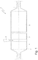
Figure 1 is a schematic view of an exhaust gas treatment device manufactured according to the present invention; -
Figure 2 is a perspective and schematic view of the treatment device ofFigure 1 ; -
Figure 3 is a perspective view of a static mixer of the treatment device ofFigure 1 ; -
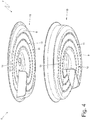
Figure 4 is an exploded view of the static mixer ofFigure 3 . - In
Figure 1 ,number 1 indicates as a whole an exhaust gas treatment device for an exhaust system of an internal combustion engine, preferably operating according to the "Diesel" cycle (i.e. supplied with diesel fuel or the like). - The exhaust
gas treatment device 1 comprises atubular housing 2, which is made of metal and has a longitudinal central shaft 3. Thetubular housing 2 houses an oxidizingcatalyst 4 arranged in the front position (namely the first to be crossed by the exhaust gas) and an SCR (Selective Catalytic Reduction)catalyst 5 for the post-treatment of the NOx molecules (NO and NO2) arranged in the rear position (namely the last to be crossed by the exhaust gas). - An
injector 6 is arranged between the oxidizingcatalyst 4 and theSCR catalyst 5, said injector being adapted to inject in the tubular housing 2 a reductant, in particular an aqueous urea solution (i.e. a solution of urea and water); in use, due to the heat of the exhaust gas in thetubular housing 2, the urea spontaneously decomposes into isocyanic acid (HNCO) and ammonia (NH3), which acts as a reducing agent within theSCR catalyst 5 to facilitate the decomposition reaction of the NOx molecules in nitrogen (N2) and water (H2O). - The
tubular housing 2 houses astatic mixer 7 arranged between the injector 6 (namely downstream of theinjector 6 with respect to the flow of exhaust gas) and the SCR catalyst 5 (namely upstream of theSCR catalyst 5 with respect to the flow of exhaust gas). Thestatic mixer 7 generates turbulence in the exhaust gas in thetubular housing 2 so as to prevent the localized densification of the isocyanic acid formed during the urea decomposition and the polymerization of the isocyanic acid, and also to increase the efficiency of theSCR catalyst 5 making more homogeneous the ammonia dispersion in the exhaust gas. According to a preferred (but not limiting) embodiment, theSCR catalyst 5 also incorporates a particulate filter. - As shown in
Figure 3 , thestatic mixer 7 comprises atubular support body 8 coaxial with the tubular housing 2 (i.e. having the same longitudinal central axis 3 of the tubular housing 2) and fixed (typically welded or riveted) to a side wall of thetubular housing 2. Furthermore, thestatic mixer 7 comprises ahelical element 9, which is helically twisted about the longitudinal central axis 3 forming a helical path, which must be followed by the exhaust gas passing through thestatic mixer 7. - Preferably, the
helical element 9 is helically twisted about the longitudinal central axis 3 with a winding angle comprised between 540° and 720°; in other words, thehelical element 9 is helically twisted about the longitudinal central axis 3 completing more than one and a half and less than two turns. According to an alternative embodiment not shown, thehelical element 9 is helically twisted about the longitudinal central axis 3 with a winding angle smaller than 540° (but still larger than 360°) or with a winding angle larger than 720°. - As shown in
Figure 4 , thestatic mixer 7 comprises two cup-shaped bodies 10, which are superposed and joined together (e.g. welded). Each cup-shaped body 10 may be manufactured by moulding a flat sheet and comprises a corresponding part of thehelical element 9. In other words, thestatic mixer 7 is formed by the union of two cup-shaped bodies 10, each including a corresponding part of thehelical element 9. When thehelical element 9 is helically twisted about the longitudinal central axis 3 with a winding angle larger than 720°, then thestatic mixer 7 is formed by the union of three (or more) cup-shaped bodies 10. - As shown in
Figures 3 and4 , thehelical element 9 comprises a plurality of throughholes 11, which are arranged along threerows 12, which are mutually parallel and spaced apart, each of them being helically twisted about the longitudinal central axis 3 following the shape of thehelical element 9. In other words, the throughholes 11 are grouped in three rows 12 (mutually parallel and spaced apart), each of which is composed by an orderly succession of evenly distributed throughholes 11 and follows (forms) a helical line which is helically twisted about the longitudinal central axis 3 following the shape of thehelical element 9. - According to a possible embodiment, along each
row 12 the throughholes 11 have a constant step (i.e. a mutual distance); alternatively, along eachrow 12 the throughholes 11 have a variable step (i.e. a mutual distance) (e.g. the step may increase and decrease more or less irregularly along the row 12). - In the preferred embodiment shown in the attached figures, the
helical element 9 comprises threerows 12 of throughholes 11; according to alternative embodiments not shown, thehelical element 9 includes only tworows 12 of through holes 11 (generally having a larger diameter) or comprises four or fiverows 12 of through holes 11 (generally having a smaller diameter). - In the preferred embodiment shown in the attached figures, the through
holes 11 are oriented longitudinally (namely, parallel to the longitudinal central axis 3); accordingly, each throughhole 11 forms an angle which is not a right angle with thehelical element 9. This latter, being helically wrapped about the longitudinal central axis 3, is never perpendicular to the longitudinal central axis 3. According to an alternative embodiment, the throughholes 11 are oriented perpendicularly with respect to thehelical element 9 and therefore are not parallel to the longitudinal central axis 3. - In the preferred embodiment shown in the attached figures, all through
holes 11 have the same diameter; according to alternative embodiments not shown, the throughholes 11 may have different diameters (the diameters of the throughholes 11 may be different in thesame row 12 and/or in the rows 12). By way of example, thethrough holes 11 may have a diameter comprised between 2 and 5 mm. - In the preferred embodiment shown in the attached figures, the
helical element 9 comprises a throughhole 13 which is oriented longitudinally (namely parallel to the longitudinal central axis 3), is centrally arranged (thus being also coaxial with the longitudinal central axis 3) and has a diameter larger than all the throughholes 11. By way of example, thethrough hole 13 may have a diameter comprised between 8 and 20 mm (therefore the throughhole 13 has a diameter that is at least 4-6 times the diameter of the through holes 11). According to a different embodiment not shown, thethrough hole 13 is not present. Theinjector 6 is arranged upstream of thestatic mixer 7 with respect to the flow of exhaust gas, and then the reductant is injected in the exhaust gas before the exhaust gas contacts thestatic mixer 7 or contacts thehelical element 9 of thestatic mixer 7. - In use, the exhaust gas can pass through the
static mixer 7 in three different ways: by following the helical path imposed by thehelical element 9, by passing through the throughholes 11 or by passing through the throughhole 13; each of these three paths imparts on the exhaust gas different whirling motions, which synergistically combine thus resulting in a good mixing of the exhaust gas. In other words, the whirling motions imparted by the three possible paths of the exhaust gas (helical element 9, throughholes 11, through hole 13) combine with each other thus increasing the total mixing effect well beyond the sum of the mixing effects obtained by using, with an equal counterpressure (namely with equal pressure losses), the three separate paths of the exhaust gas (i.e. in series, one after the other). - The aforesaid
static mixer 13 has numerous advantages, since it is simple and inexpensive to manufacture, is particularly tough (therefore having a long service life and a very low risk of fractures) and especially has an optimal balance between the conflicting requirements relating to efficacy (i.e. ensuring an adequate mixing of the exhaust gas) and efficiency (i.e. limiting the load losses in the exhaust gas). In other words, the aforesaidstatic mixer 13 has at the same time a high efficacy (i.e. it ensures an adequate mixing of the exhaust gas) and a high efficiency (i.e. it limits the load losses in the exhaust gas).
Claims (7)
- An exhaust gas treatment device (1) for an exhaust system of an internal combustion engine; the treatment device (1) comprises:a tubular housing (2), which has a longitudinal central axis (3); anda static mixer (7), which is arranged inside the tubular housing (2) and comprises a helical element (9), which is helically twisted about the longitudinal central axis (3) and comprises at least two rows (12) of first through holes (11), which are mutually spaced;wherein the two rows (12) of first through holes (11) are parallel and spaced apart, each of them being helically twisted about the longitudinal central axis (3) following the shape of the helical element (9); andwherein there are provided two separate cup-shaped bodies (10), which are superposed, each of them comprising a corresponding part of the helical element (9);the treatment device (1) is characterized in that the helical element (9) comprises a second through hole (13) which is longitudinally oriented, is centrally arranged and has a diameter larger than the first through holes (11).
- A treatment device (1) according to claim 1, wherein the helical element (9) comprises three rows (12) of first through holes (11).
- A treatment device (1) according to claim 1 or 2, wherein the first through holes (11) all have the same diameter.
- A treatment device (1) according to claim 1, 2 or 3, wherein the helical element (9) is helically twisted about the longitudinal central axis (3) with a winding angle ranging from 540° to 720°.
- A treatment device (1) according to any one of claims from 1 to 4, wherein the first through holes (11) are longitudinally oriented.
- An exhaust gas treatment device (1) according to any one of claims from 1 to 5 and comprising:a SCR catalytic converter (9), which is arranged in the tubular housing (2) downstream of the static mixer (7); andan injector (6), which injects an additive in the tubular housing and is arranged in the tubular housing upstream of the static mixer (7).
- A treatment device (1) according to claim 6, wherein the injector (6) injects the additive upstream of the helical element (9) of the static mixer (7).
Applications Claiming Priority (1)
| Application Number | Priority Date | Filing Date | Title |
|---|---|---|---|
| ITUB2015A003526A ITUB20153526A1 (en) | 2015-09-10 | 2015-09-10 | EXHAUST GAS TREATMENT DEVICE FOR AN INTERNAL COMBUSTION ENGINE EXHAUST SYSTEM |
Publications (2)
| Publication Number | Publication Date |
|---|---|
| EP3141297A1 true EP3141297A1 (en) | 2017-03-15 |
| EP3141297B1 EP3141297B1 (en) | 2018-09-05 |
Family
ID=54843980
Family Applications (1)
| Application Number | Title | Priority Date | Filing Date |
|---|---|---|---|
| EP16187972.1A Active EP3141297B1 (en) | 2015-09-10 | 2016-09-09 | Exhaust gas treatement device for an exhaust system of an internal combustion engine |
Country Status (3)
| Country | Link |
|---|---|
| EP (1) | EP3141297B1 (en) |
| ES (1) | ES2688109T3 (en) |
| IT (1) | ITUB20153526A1 (en) |
Cited By (1)
| Publication number | Priority date | Publication date | Assignee | Title |
|---|---|---|---|---|
| US20250237160A1 (en) * | 2024-01-18 | 2025-07-24 | Cummins Emission Solutions Inc. | Mixer for exhaust aftertreatment system |
Citations (2)
| Publication number | Priority date | Publication date | Assignee | Title |
|---|---|---|---|---|
| US20130216442A1 (en) * | 2010-10-18 | 2013-08-22 | Faurecia Systemes D'echappement | Motor Vehicle Exhaust Line |
| EP2823880A1 (en) * | 2013-07-08 | 2015-01-14 | Toyota Jidosha Kabushiki Kaisha | Exhaust gas purification appratus for an internal combustion engine |
Family Cites Families (1)
| Publication number | Priority date | Publication date | Assignee | Title |
|---|---|---|---|---|
| EP3198122B1 (en) * | 2014-09-23 | 2018-07-25 | Officine Metallurgiche G. Cornaglia S.p.A. | Exhaust gas reduction unit for internal combustion engine |
-
2015
- 2015-09-10 IT ITUB2015A003526A patent/ITUB20153526A1/en unknown
-
2016
- 2016-09-09 ES ES16187972.1T patent/ES2688109T3/en active Active
- 2016-09-09 EP EP16187972.1A patent/EP3141297B1/en active Active
Patent Citations (2)
| Publication number | Priority date | Publication date | Assignee | Title |
|---|---|---|---|---|
| US20130216442A1 (en) * | 2010-10-18 | 2013-08-22 | Faurecia Systemes D'echappement | Motor Vehicle Exhaust Line |
| EP2823880A1 (en) * | 2013-07-08 | 2015-01-14 | Toyota Jidosha Kabushiki Kaisha | Exhaust gas purification appratus for an internal combustion engine |
Cited By (1)
| Publication number | Priority date | Publication date | Assignee | Title |
|---|---|---|---|---|
| US20250237160A1 (en) * | 2024-01-18 | 2025-07-24 | Cummins Emission Solutions Inc. | Mixer for exhaust aftertreatment system |
Also Published As
| Publication number | Publication date |
|---|---|
| ITUB20153526A1 (en) | 2017-03-10 |
| EP3141297B1 (en) | 2018-09-05 |
| ES2688109T3 (en) | 2018-10-30 |
Similar Documents
| Publication | Publication Date | Title |
|---|---|---|
| US11193412B2 (en) | Automotive exhaust aftertreatment system | |
| US11268424B2 (en) | Exhaust gas purification device | |
| EP1982756A1 (en) | An exhaust system of an internal combustion engine | |
| US9482132B2 (en) | Gaseous reductant delivery devices and systems | |
| CN214273771U (en) | Aftertreatment exhaust gas mixer, exhaust line and vehicle | |
| EP3102802B1 (en) | Mixer assembly for a vehicle exhaust system | |
| EP2803833B1 (en) | Exhaust gas purification device | |
| KR101598946B1 (en) | Exhaust gas additive/treatment system and mixer for use therein | |
| CN105221223B (en) | Exhaust aftertreatment device for internal combustion engine and vehicle having the same | |
| US9057312B2 (en) | System and apparatus for reducing reductant deposit formation in exhaust aftertreatment systems | |
| US20140325967A1 (en) | Exhaust gas purification device | |
| US20110219745A1 (en) | Method and apparatus for gaseous mixing in a diesel exhaust system | |
| JP2008151088A (en) | Exhaust purification device | |
| US20140053538A1 (en) | Reductant injection and mixing system | |
| DE112010000852T5 (en) | Fastening device for an emission system with reducing agent admixture | |
| US20160194995A1 (en) | Flow mixing device for an exhaust after-treatment system | |
| US8443595B2 (en) | Additive-agent diffusion plate in exhaust passage, structure of additive-agent diffusion plate, and exhaust system including additive-agent diffusion plate | |
| US20160326937A1 (en) | Plenum chamber for exhaust system | |
| EP3438426A1 (en) | Exhaust purification system | |
| CN114526141A (en) | Aftertreatment system and method of treating exhaust gas | |
| US11691120B1 (en) | Exhaust gas aftertreatment systems | |
| US20160245142A1 (en) | Reductant injector mount | |
| JP2013002337A (en) | Exhaust gas postprocessing device | |
| EP3141297B1 (en) | Exhaust gas treatement device for an exhaust system of an internal combustion engine | |
| EP2180156A1 (en) | Injection system for injecting a reducing substance into an exhaust system of an internal combustion engine |
Legal Events
| Date | Code | Title | Description |
|---|---|---|---|
| PUAI | Public reference made under article 153(3) epc to a published international application that has entered the european phase |
Free format text: ORIGINAL CODE: 0009012 |
|
| AK | Designated contracting states |
Kind code of ref document: A1 Designated state(s): AL AT BE BG CH CY CZ DE DK EE ES FI FR GB GR HR HU IE IS IT LI LT LU LV MC MK MT NL NO PL PT RO RS SE SI SK SM TR |
|
| AX | Request for extension of the european patent |
Extension state: BA ME |
|
| 17P | Request for examination filed |
Effective date: 20170914 |
|
| GRAP | Despatch of communication of intention to grant a patent |
Free format text: ORIGINAL CODE: EPIDOSNIGR1 |
|
| RIC1 | Information provided on ipc code assigned before grant |
Ipc: B01F 3/04 20060101AFI20180216BHEP Ipc: F01N 3/20 20060101ALI20180216BHEP Ipc: B01F 5/04 20060101ALI20180216BHEP Ipc: B01F 5/06 20060101ALI20180216BHEP |
|
| INTG | Intention to grant announced |
Effective date: 20180323 |
|
| RAP1 | Party data changed (applicant data changed or rights of an application transferred) |
Owner name: MAGNETI MARELLI S.P.A. |
|
| GRAS | Grant fee paid |
Free format text: ORIGINAL CODE: EPIDOSNIGR3 |
|
| GRAA | (expected) grant |
Free format text: ORIGINAL CODE: 0009210 |
|
| AK | Designated contracting states |
Kind code of ref document: B1 Designated state(s): AL AT BE BG CH CY CZ DE DK EE ES FI FR GB GR HR HU IE IS IT LI LT LU LV MC MK MT NL NO PL PT RO RS SE SI SK SM TR |
|
| REG | Reference to a national code |
Ref country code: GB Ref legal event code: FG4D |
|
| REG | Reference to a national code |
Ref country code: CH Ref legal event code: EP |
|
| REG | Reference to a national code |
Ref country code: AT Ref legal event code: REF Ref document number: 1037191 Country of ref document: AT Kind code of ref document: T Effective date: 20180915 |
|
| REG | Reference to a national code |
Ref country code: IE Ref legal event code: FG4D |
|
| REG | Reference to a national code |
Ref country code: DE Ref legal event code: R096 Ref document number: 602016005310 Country of ref document: DE |
|
| REG | Reference to a national code |
Ref country code: FR Ref legal event code: PLFP Year of fee payment: 3 |
|
| REG | Reference to a national code |
Ref country code: ES Ref legal event code: FG2A Ref document number: 2688109 Country of ref document: ES Kind code of ref document: T3 Effective date: 20181030 |
|
| REG | Reference to a national code |
Ref country code: NL Ref legal event code: MP Effective date: 20180905 |
|
| REG | Reference to a national code |
Ref country code: LT Ref legal event code: MG4D |
|
| PG25 | Lapsed in a contracting state [announced via postgrant information from national office to epo] |
Ref country code: SE Free format text: LAPSE BECAUSE OF FAILURE TO SUBMIT A TRANSLATION OF THE DESCRIPTION OR TO PAY THE FEE WITHIN THE PRESCRIBED TIME-LIMIT Effective date: 20180905 Ref country code: BG Free format text: LAPSE BECAUSE OF FAILURE TO SUBMIT A TRANSLATION OF THE DESCRIPTION OR TO PAY THE FEE WITHIN THE PRESCRIBED TIME-LIMIT Effective date: 20181205 Ref country code: FI Free format text: LAPSE BECAUSE OF FAILURE TO SUBMIT A TRANSLATION OF THE DESCRIPTION OR TO PAY THE FEE WITHIN THE PRESCRIBED TIME-LIMIT Effective date: 20180905 Ref country code: RS Free format text: LAPSE BECAUSE OF FAILURE TO SUBMIT A TRANSLATION OF THE DESCRIPTION OR TO PAY THE FEE WITHIN THE PRESCRIBED TIME-LIMIT Effective date: 20180905 Ref country code: NO Free format text: LAPSE BECAUSE OF FAILURE TO SUBMIT A TRANSLATION OF THE DESCRIPTION OR TO PAY THE FEE WITHIN THE PRESCRIBED TIME-LIMIT Effective date: 20181205 Ref country code: GR Free format text: LAPSE BECAUSE OF FAILURE TO SUBMIT A TRANSLATION OF THE DESCRIPTION OR TO PAY THE FEE WITHIN THE PRESCRIBED TIME-LIMIT Effective date: 20181206 Ref country code: LT Free format text: LAPSE BECAUSE OF FAILURE TO SUBMIT A TRANSLATION OF THE DESCRIPTION OR TO PAY THE FEE WITHIN THE PRESCRIBED TIME-LIMIT Effective date: 20180905 |
|
| REG | Reference to a national code |
Ref country code: AT Ref legal event code: MK05 Ref document number: 1037191 Country of ref document: AT Kind code of ref document: T Effective date: 20180905 |
|
| PG25 | Lapsed in a contracting state [announced via postgrant information from national office to epo] |
Ref country code: LV Free format text: LAPSE BECAUSE OF FAILURE TO SUBMIT A TRANSLATION OF THE DESCRIPTION OR TO PAY THE FEE WITHIN THE PRESCRIBED TIME-LIMIT Effective date: 20180905 Ref country code: HR Free format text: LAPSE BECAUSE OF FAILURE TO SUBMIT A TRANSLATION OF THE DESCRIPTION OR TO PAY THE FEE WITHIN THE PRESCRIBED TIME-LIMIT Effective date: 20180905 Ref country code: AL Free format text: LAPSE BECAUSE OF FAILURE TO SUBMIT A TRANSLATION OF THE DESCRIPTION OR TO PAY THE FEE WITHIN THE PRESCRIBED TIME-LIMIT Effective date: 20180905 |
|
| PG25 | Lapsed in a contracting state [announced via postgrant information from national office to epo] |
Ref country code: RO Free format text: LAPSE BECAUSE OF FAILURE TO SUBMIT A TRANSLATION OF THE DESCRIPTION OR TO PAY THE FEE WITHIN THE PRESCRIBED TIME-LIMIT Effective date: 20180905 Ref country code: CZ Free format text: LAPSE BECAUSE OF FAILURE TO SUBMIT A TRANSLATION OF THE DESCRIPTION OR TO PAY THE FEE WITHIN THE PRESCRIBED TIME-LIMIT Effective date: 20180905 Ref country code: IS Free format text: LAPSE BECAUSE OF FAILURE TO SUBMIT A TRANSLATION OF THE DESCRIPTION OR TO PAY THE FEE WITHIN THE PRESCRIBED TIME-LIMIT Effective date: 20190105 Ref country code: PL Free format text: LAPSE BECAUSE OF FAILURE TO SUBMIT A TRANSLATION OF THE DESCRIPTION OR TO PAY THE FEE WITHIN THE PRESCRIBED TIME-LIMIT Effective date: 20180905 Ref country code: NL Free format text: LAPSE BECAUSE OF FAILURE TO SUBMIT A TRANSLATION OF THE DESCRIPTION OR TO PAY THE FEE WITHIN THE PRESCRIBED TIME-LIMIT Effective date: 20180905 Ref country code: AT Free format text: LAPSE BECAUSE OF FAILURE TO SUBMIT A TRANSLATION OF THE DESCRIPTION OR TO PAY THE FEE WITHIN THE PRESCRIBED TIME-LIMIT Effective date: 20180905 Ref country code: EE Free format text: LAPSE BECAUSE OF FAILURE TO SUBMIT A TRANSLATION OF THE DESCRIPTION OR TO PAY THE FEE WITHIN THE PRESCRIBED TIME-LIMIT Effective date: 20180905 Ref country code: IT Free format text: LAPSE BECAUSE OF FAILURE TO SUBMIT A TRANSLATION OF THE DESCRIPTION OR TO PAY THE FEE WITHIN THE PRESCRIBED TIME-LIMIT Effective date: 20180905 |
|
| PG25 | Lapsed in a contracting state [announced via postgrant information from national office to epo] |
Ref country code: SK Free format text: LAPSE BECAUSE OF FAILURE TO SUBMIT A TRANSLATION OF THE DESCRIPTION OR TO PAY THE FEE WITHIN THE PRESCRIBED TIME-LIMIT Effective date: 20180905 Ref country code: SM Free format text: LAPSE BECAUSE OF FAILURE TO SUBMIT A TRANSLATION OF THE DESCRIPTION OR TO PAY THE FEE WITHIN THE PRESCRIBED TIME-LIMIT Effective date: 20180905 Ref country code: PT Free format text: LAPSE BECAUSE OF FAILURE TO SUBMIT A TRANSLATION OF THE DESCRIPTION OR TO PAY THE FEE WITHIN THE PRESCRIBED TIME-LIMIT Effective date: 20190105 |
|
| REG | Reference to a national code |
Ref country code: DE Ref legal event code: R097 Ref document number: 602016005310 Country of ref document: DE |
|
| REG | Reference to a national code |
Ref country code: BE Ref legal event code: MM Effective date: 20180930 |
|
| REG | Reference to a national code |
Ref country code: IE Ref legal event code: MM4A |
|
| PG25 | Lapsed in a contracting state [announced via postgrant information from national office to epo] |
Ref country code: LU Free format text: LAPSE BECAUSE OF NON-PAYMENT OF DUE FEES Effective date: 20180909 |
|
| PLBE | No opposition filed within time limit |
Free format text: ORIGINAL CODE: 0009261 |
|
| STAA | Information on the status of an ep patent application or granted ep patent |
Free format text: STATUS: NO OPPOSITION FILED WITHIN TIME LIMIT |
|
| PG25 | Lapsed in a contracting state [announced via postgrant information from national office to epo] |
Ref country code: DK Free format text: LAPSE BECAUSE OF FAILURE TO SUBMIT A TRANSLATION OF THE DESCRIPTION OR TO PAY THE FEE WITHIN THE PRESCRIBED TIME-LIMIT Effective date: 20180905 Ref country code: MC Free format text: LAPSE BECAUSE OF FAILURE TO SUBMIT A TRANSLATION OF THE DESCRIPTION OR TO PAY THE FEE WITHIN THE PRESCRIBED TIME-LIMIT Effective date: 20180905 Ref country code: IE Free format text: LAPSE BECAUSE OF NON-PAYMENT OF DUE FEES Effective date: 20180909 |
|
| 26N | No opposition filed |
Effective date: 20190606 |
|
| PG25 | Lapsed in a contracting state [announced via postgrant information from national office to epo] |
Ref country code: BE Free format text: LAPSE BECAUSE OF NON-PAYMENT OF DUE FEES Effective date: 20180930 Ref country code: SI Free format text: LAPSE BECAUSE OF FAILURE TO SUBMIT A TRANSLATION OF THE DESCRIPTION OR TO PAY THE FEE WITHIN THE PRESCRIBED TIME-LIMIT Effective date: 20180905 |
|
| PG25 | Lapsed in a contracting state [announced via postgrant information from national office to epo] |
Ref country code: MT Free format text: LAPSE BECAUSE OF NON-PAYMENT OF DUE FEES Effective date: 20180909 |
|
| PG25 | Lapsed in a contracting state [announced via postgrant information from national office to epo] |
Ref country code: TR Free format text: LAPSE BECAUSE OF FAILURE TO SUBMIT A TRANSLATION OF THE DESCRIPTION OR TO PAY THE FEE WITHIN THE PRESCRIBED TIME-LIMIT Effective date: 20180905 |
|
| REG | Reference to a national code |
Ref country code: CH Ref legal event code: PL |
|
| PG25 | Lapsed in a contracting state [announced via postgrant information from national office to epo] |
Ref country code: MK Free format text: LAPSE BECAUSE OF NON-PAYMENT OF DUE FEES Effective date: 20180905 Ref country code: CY Free format text: LAPSE BECAUSE OF FAILURE TO SUBMIT A TRANSLATION OF THE DESCRIPTION OR TO PAY THE FEE WITHIN THE PRESCRIBED TIME-LIMIT Effective date: 20180905 Ref country code: HU Free format text: LAPSE BECAUSE OF FAILURE TO SUBMIT A TRANSLATION OF THE DESCRIPTION OR TO PAY THE FEE WITHIN THE PRESCRIBED TIME-LIMIT; INVALID AB INITIO Effective date: 20160909 |
|
| PG25 | Lapsed in a contracting state [announced via postgrant information from national office to epo] |
Ref country code: CH Free format text: LAPSE BECAUSE OF NON-PAYMENT OF DUE FEES Effective date: 20190930 Ref country code: LI Free format text: LAPSE BECAUSE OF NON-PAYMENT OF DUE FEES Effective date: 20190930 |
|
| REG | Reference to a national code |
Ref country code: DE Ref legal event code: R079 Ref document number: 602016005310 Country of ref document: DE Free format text: PREVIOUS MAIN CLASS: B01F0003040000 Ipc: B01F0023200000 |
|
| PGFP | Annual fee paid to national office [announced via postgrant information from national office to epo] |
Ref country code: DE Payment date: 20250820 Year of fee payment: 10 |
|
| PGFP | Annual fee paid to national office [announced via postgrant information from national office to epo] |
Ref country code: GB Payment date: 20250822 Year of fee payment: 10 |
|
| PGFP | Annual fee paid to national office [announced via postgrant information from national office to epo] |
Ref country code: FR Payment date: 20250820 Year of fee payment: 10 |
|
| PGFP | Annual fee paid to national office [announced via postgrant information from national office to epo] |
Ref country code: ES Payment date: 20251001 Year of fee payment: 10 |