EP3141095A1 - Agricultural machine - Google Patents
Agricultural machine Download PDFInfo
- Publication number
- EP3141095A1 EP3141095A1 EP16186791.6A EP16186791A EP3141095A1 EP 3141095 A1 EP3141095 A1 EP 3141095A1 EP 16186791 A EP16186791 A EP 16186791A EP 3141095 A1 EP3141095 A1 EP 3141095A1
- Authority
- EP
- European Patent Office
- Prior art keywords
- hinge
- pin
- section
- center section
- fastener
- Prior art date
- Legal status (The legal status is an assumption and is not a legal conclusion. Google has not performed a legal analysis and makes no representation as to the accuracy of the status listed.)
- Granted
Links
Images



Classifications
-
- A—HUMAN NECESSITIES
- A01—AGRICULTURE; FORESTRY; ANIMAL HUSBANDRY; HUNTING; TRAPPING; FISHING
- A01B—SOIL WORKING IN AGRICULTURE OR FORESTRY; PARTS, DETAILS, OR ACCESSORIES OF AGRICULTURAL MACHINES OR IMPLEMENTS, IN GENERAL
- A01B73/00—Means or arrangements to facilitate transportation of agricultural machines or implements, e.g. folding frames to reduce overall width
- A01B73/02—Folding frames
- A01B73/04—Folding frames foldable about a horizontal axis
- A01B73/044—Folding frames foldable about a horizontal axis the axis being oriented in a longitudinal direction
-
- A—HUMAN NECESSITIES
- A01—AGRICULTURE; FORESTRY; ANIMAL HUSBANDRY; HUNTING; TRAPPING; FISHING
- A01B—SOIL WORKING IN AGRICULTURE OR FORESTRY; PARTS, DETAILS, OR ACCESSORIES OF AGRICULTURAL MACHINES OR IMPLEMENTS, IN GENERAL
- A01B73/00—Means or arrangements to facilitate transportation of agricultural machines or implements, e.g. folding frames to reduce overall width
- A01B73/02—Folding frames
Definitions
- This disclosure relates generally to an agricultural machine and in particular to pivoting pins and hinges used in such.
- Agricultural implements and machines including various cultivators, plows, tillers, rippers, seeders, nutrient applicators, etc., are used to work the soil of crop fields. These two to five thousand pound implements and machines are often towed behind tractors. Tillage and other agricultural implements in particular perform a variety of tasks, such as breaking up tough ground, turning the soil, and eradicating weeds. Traveling at 10 to 15 mph, the impact of portions of these implements or machines with the ground generates large forces on certain components (e.g. hinges, flanges, shanks, disks, gangs, and electronics).
- components e.g. hinges, flanges, shanks, disks, gangs, and electronics.
- Embodiments include hinges or pivotal joints that are buttressed by bolts or bushings so that the hinge pin does not fall out.
- Other embodiments are disclosed in the detailed description, accompanying drawings and claims.
- Some embodiments include an agricultural machine having a center section, a wheel supporting the center section, a wing section coupled to the center section, and a hinge positioned between the center section and the wing section.
- the hinge permits the wing section to pivot about the center section.
- the hinge includes a first part having a first protrusion defining a first aperture, the first part is connected to the center section, a second part having a second protrusion, the second protrusion defining a second aperture, the second part is coupled to the wing section, and a pin having a first end and a second end. The pin extends through the first and second apertures to connect the first part and the second part such that the wing section can be pivoted with respect to the center section.
- a first fastener is positioned adjacent the first end of the pin.
- the first fastener is operable to couple the first part to the center section and to abut the first end of the pin to thereby retain the pin in the first and second apertures.
- a second fastener is positioned adjacent the second end of the pin. The second fastener operable to couple the first part to the center section and to abut the second end of the pin to thereby retain the pin in the first and second apertures.
- Some embodiments include a hinge for an agricultural machine having a center section, a wheel supporting the center section, a wing section connected to the center section, and a hinge positioned between the center section and the wing section.
- the hinge permits the wing section to pivot about the center section.
- the hinge includes a first part having a first protrusion and defining a first aperture, the first part is connected to the center section, a second part having a second protrusion and defining a second aperture, the second part is connected to the wing section, and a pin having a first end and a second end. The pin extends through the first and second apertures to connect the first part and the second part such that the wing section can pivot with respect to the center section.
- a first fastener is adjacent to the first end of the pin.
- the first fastener connects the second part to the wing section and abuts the first end of the pin to thereby retain the pin in the first and second apertures.
- a second fastener is adjacent to the second end of the pin. The second fastener connects the second part to the wing section and abuts the second end of the pin to thereby retain the pin in the first and second apertures.
- Some embodiments include an agricultural machine that has a center section having a first aperture, a wheel supporting the center section, a wing section connected to the center section and having a second aperture, and a hinge positioned between the center section and the wing section to permit the wing section to pivot about the center section.
- the hinge includes a pin having a first end and a second end. The pin extends through the first and second apertures to connect the wing section to the center section.
- a first fastener engages the center section or the wing section and is adjacent to the first end of the pin to thereby retain the pin in the first and second apertures.
- a second fastener engages the center section or the wing section and is adjacent to the second end of the pin to thereby retain the pin in the first and second apertures.
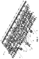
- FIG. 1 shows an example tillage implement in which hinges are incorporated.
- the hinged tillage implement is illustrated as a multi-section, articulated field cultivator 20 with wings.
- Arrow 21 indicates the direction of travel of the cultivator 20.
- the cultivator 20 includes five frame sections, which are pivotally-hinge joined in a foldable configuration. From left to right in Fig. 1 , the frame sections include: (i) a first outer wing section 23, (ii) a first inner wing section 24, (iii) a main frame section 25, (iv) a second inner wing section 26, and (v) a second outer wing section 27.
- the inner wing sections 24 and 26 are hinged together at opposing lateral sides of the main frame section 25 and can pivot about first and second inner hinge lines 30, respectively.
- the outer wing sections 23 and 27 are pivotally hinged together at the lateral outer sides of the inner wing sections 24 and 26, respectively, and can pivot about first and second outer hinge lines 32.
- the hinge lines 30 and 32 may alternatively be referred to as "fore-aft hinge axes.”
- the cultivator wing sections fold above and rotate over (pivot around) the hinge lines 30 and 32.
- Such a multi-section hinged design enables the cultivator 20 to transition from the unfolded operational state shown in Fig. 1 to a laterally compact, folded state to facilitate transport on roadways.
- the cultivator 20 is supported by a plurality of wheels 40.
- other agricultural machines include planters or sprayers that have articulated sections.
- sprayers have articulated air booms or fluid distribution booms.
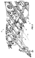
- FIG. 2 depicts a top perspective magnified view of the main frame section 25 and the second inner wing section 26 of the cultivator of Fig. 1 .
- a hinge system 50 is circled. Hinge systems 50 are located where the frame of the cultivator 20 rotates about hinge lines 30 or 32. The frame of cultivator 20 bends and folds so that a plane of the wing sections 23 and 24 can be positioned upright and perpendicular to the ground.
- the hinge system 50 can include jointed devices, pin joints, pivot hinges, barrel hinges, leaf hinges, butt hinges, and so on.
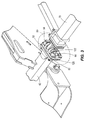
- Figure 3 depicts an example embodiment of the hinge system 50 that includes a first hinge part 52 and a second hinge part 54 that mate to each other.
- first hinge part 52 is termed a receiving or female part of a hinge and the second hinge part 54 is a tongue or male part of a hinge.
- the illustrated hinge parts 52 and 54 are joined together by a pivot connection via a hinge pin 82.
- the hinge parts 52 and 54 are mounted to frame members on adjacent sections of field cultivator 20 (e.g. Fig. 1 ).
- the first hinge part 52 is mounted to an end of a lateral frame member 62 in the main frame section 25 ( Fig. 1 ), while the second hinge part 54 is mounted to an end of a lateral frame member 70 included in the second inner wing section 26.
- Any combination of structural features, welding, mounting hardware, and/or joinder techniques can be utilized to attach the hinge parts 52 and 54 to their respective frame members 62 and 70.
- the illustrated first hinge part 52 includes a hinge plate 56 and two half circular rings or clevises 58.
- the clevises 58 are manufactured as a single piece (e.g. casting) with the hinge plate 56.
- the illustrated hinge plate 56 can extend out beyond an outer lateral width W 1 of the pair of clevises 58.
- the hinge illustrated hinge plate 56 extends out a distance W 2 on either side of the two clevises 58 of hinge part 52.
- the overall hinge plate width is W 3 .
- the hinge plate 56 is narrower than depicted in Fig. 5 .
- the width W 3 of hinge plate 56 can be only 5% to 10% wider than the outer lateral width W 1 of the pair of clevises 58.
- Hinge plate 56 is bolted to or mounted to a flange 60 that is attached to the rest of the frame section of the cultivator 20.
- the hinge parts 52 and 54 can include any number and type of mating features to form the pivotal or hinge coupling. Either or both of the hinge parts 52 and 54 can include one or more male connector features, female connector features, or combinations thereof.
- the hinge parts 52 and 54 include a number of knuckles and fingers, respectively, which mate in an interleaved or alternating configuration to form a hinge joint.
- the hinge part 52 includes a pair of clevises 58 that protrude out substantially perpendicular to the mounting flange 60. The two clevises 58 are substantially parallel to each other and separated by a groove 72.
- the second hinge part 54 includes a male connector feature in the form of a tongue 68, which is received within the groove 72 when the hinge system 50 is assembled. When received within the groove 72, the tongue 68 can rotate relative to the first hinge part 52 about a hinge line axis 51 (see FIG. 5 ), which is coaxial with the rightmost fore-aft hinge line 30 shown in FIGS. 1 and 2 .
- openings 74 are defined by the first hinge part 52 and an opening 76 is defined by the tongue 68 of second hinge part 54.
- the opening 76 aligns with corresponding openings 74 located in the clevises 58.
- a hinge pin 82 is inserted into aligning openings 74 and 76 to provide the hinge coupling.
- the hinge pin 82 has a smooth-surface cylindrical section for pivotally joining together the hinge parts 52 and 54.
- the hinge pin 82 can include an anchor, bolt, dowel pin or flag pin.
- Figs. 3 - 5 illustrate bolts 64, bushings 120, bolts 122, and nuts 124 (located behind flange 60, a nut, or nut and washer, or cap nut, and so on).
- the bushings 120 have a first length L 1 protruding from the hinge plate 56.
- the top of the hinge pin 82 is positioned a second length L 2 from the hinge plate 56.
- the first length L 1 is greater than L 2 so that the bushings 120 overlap at least a portion of the respective ends of the pin 82.
- the illustrated bushings 120 are substantially centered with the hinge pin 82. In the illustrated embodiment, the bushings 120 overlap a majority of the end of the hinge pin 82. In some embodiments, the bushings 120 can cover the entire ends of the hinge pin 82.
- the bushings 120 prevent the pin 82 from falling out of the openings 74 and 76.
- the bottom of bushing 120 either directly contacts the hinge plate 56 or there is an epoxy or some other adhesive between the bushing 120 and the hinge plate 56.
- the contact surface between the hinge plate 56 and the bottom of the bushing 120 is sanded or roughened so as to increase the friction to form a better contact.
- the nut 124 that is screwed onto the bolt 122 can also be adhesively contacted to the flange 60. In yet other embodiments, a combination of these techniques is used to form a tighter contact or bond between the bushing 120 and the hinge plate 56.
- the illustrated bushings 120 have a circular cross section with a substantially constant diameter.
- the bushings can have a hexagonal, an octagonal or a square cross section.
- the bushings can have a variable cross section.
- Figure 7 illustrates an alternative embodiment of a bushing 122' that is tapered in shape.
- the base of the bushing 120' is larger nearest the hinge plate 56.
- a larger base can increase the stability of the bushing 120', increasing its ability to remain stationary if the hinge pin 82 presses against the bushing 120'.
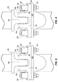
- Fig. 7A depicts another embodiment where a bushing 120" has a narrower surface area where the bushing 120" meets the hinge plate 56.
- a narrower surface area is useful in situations where the extended area of the hinge plate 56 is small and can only accommodate a thinner or more slender buttress. Also since the bushing 120" widens up near the hinge pin 82, the hinge pin 82 can be abutted by the bushing 120".
- the hinge plate can be recessed to receive at least a portion of the bushing.
- Figure 8 depicts an embodiment of a hinge plate 256 including a recess 257 into which a bushing 320 fits.
- the recess 257 is an opening that is large enough to accommodate the base diameter of the bushing 320.
- the depth of the recess 257 depends on the thickness of hinge plate 256. For example, the depth may nominally be 5 - 10% of the thickness of hinge plate 256. But if the hinge plate 256 is thick (e.g. 1 - 2 inches), the depth can be increased to 10 - 25%.
- the bushing 320 is more anchored and stable when placed in the recess 257 and less likely to move than if it were located only on the surface of hinge plate 256.
- the remaining elements of Figure 8 correspond to Figures 3-6 , but are numbered in the "200" series.
- Figure 9 depicts another embodiment of a hinge plate 256 including a recess 257 that receives a portion of a bushing 320'.
- the recess 257 is an opening that is large enough to accommodate at least the base diameter of the half-cone bushing 320'.
- the illustrated bushing 320' is conical, but in other embodiments, the bushing may be a half-pyramid or have a cross section that is hexagonal, octagonal or square.
- the depth of recess 257 again depends on the thickness of hinge plate 256.
- the recess 257 can extend about 5 - 10% of the thickness is suitable without compromising the structural integrity of the hinge plate 256.
- the remaining elements of Figure 9 correspond to Figures 3-6 , but are numbered in the "200" series.
- Figure 9A depicts yet another embodiment of a hinge plate 456 including a recess 457 that receives a portion of a bushing 520.
- the recess 457 is large enough to accommodate at least the top (narrower) diameter of the half-cone bushing 520. Since the area of the bushing 520 that contacts the hinge plate 456 is now smaller, the diameter or area of the recess 457 is now also correspondingly smaller.
- the remaining elements of Figure 9A correspond to Figures 3-6 , but are numbered in the "400" series.
- Figure 9B depicts yet another embodiment a hinge plate 656 that includes a recess 657 in which a bushing 720 fits.
- the recess 657 has an opening that is shaped so as to key-mated (interlocked) to the shape of the base diameter of the bushing 720.
- the opening of recess 657 extends to the top edge of the hinge plate 656.
- the hinge system 50 provides a pivot connection between the frame member 62 of the main frame section 25 and the frame member 70 of the second inner wing section 26.
- This hinged connection along with other hinged connections included within the winged field cultivator 20, allows the second inner wing section 26 to rotate upwardly with respect to the main frame section 25 when the winged field cultivator 20 transitions from its unfolded operational to the folded transport state.
- the bushings 120, 120', 120", 320, 320', 520 and 720 prevent the respective hinge pin 82, 282, 482 and 682 from falling out.
Landscapes
- Life Sciences & Earth Sciences (AREA)
- Engineering & Computer Science (AREA)
- Mechanical Engineering (AREA)
- Soil Sciences (AREA)
- Environmental Sciences (AREA)
- Agricultural Machines (AREA)
- Pivots And Pivotal Connections (AREA)
- Soil Working Implements (AREA)
Abstract
Description
- This disclosure relates generally to an agricultural machine and in particular to pivoting pins and hinges used in such.
- Agricultural implements and machines, including various cultivators, plows, tillers, rippers, seeders, nutrient applicators, etc., are used to work the soil of crop fields. These two to five thousand pound implements and machines are often towed behind tractors. Tillage and other agricultural implements in particular perform a variety of tasks, such as breaking up tough ground, turning the soil, and eradicating weeds. Traveling at 10 to 15 mph, the impact of portions of these implements or machines with the ground generates large forces on certain components (e.g. hinges, flanges, shanks, disks, gangs, and electronics).
- Various aspects of example embodiments are set out below and in the claims. Embodiments include hinges or pivotal joints that are buttressed by bolts or bushings so that the hinge pin does not fall out. Other embodiments are disclosed in the detailed description, accompanying drawings and claims.
- Some embodiments include an agricultural machine having a center section, a wheel supporting the center section, a wing section coupled to the center section, and a hinge positioned between the center section and the wing section. The hinge permits the wing section to pivot about the center section. The hinge includes a first part having a first protrusion defining a first aperture, the first part is connected to the center section, a second part having a second protrusion, the second protrusion defining a second aperture, the second part is coupled to the wing section, and a pin having a first end and a second end. The pin extends through the first and second apertures to connect the first part and the second part such that the wing section can be pivoted with respect to the center section. A first fastener is positioned adjacent the first end of the pin. The first fastener is operable to couple the first part to the center section and to abut the first end of the pin to thereby retain the pin in the first and second apertures. A second fastener is positioned adjacent the second end of the pin. The second fastener operable to couple the first part to the center section and to abut the second end of the pin to thereby retain the pin in the first and second apertures.
- Some embodiments include a hinge for an agricultural machine having a center section, a wheel supporting the center section, a wing section connected to the center section, and a hinge positioned between the center section and the wing section. The hinge permits the wing section to pivot about the center section. The hinge includes a first part having a first protrusion and defining a first aperture, the first part is connected to the center section, a second part having a second protrusion and defining a second aperture, the second part is connected to the wing section, and a pin having a first end and a second end. The pin extends through the first and second apertures to connect the first part and the second part such that the wing section can pivot with respect to the center section. A first fastener is adjacent to the first end of the pin. The first fastener connects the second part to the wing section and abuts the first end of the pin to thereby retain the pin in the first and second apertures. A second fastener is adjacent to the second end of the pin. The second fastener connects the second part to the wing section and abuts the second end of the pin to thereby retain the pin in the first and second apertures.
- Some embodiments include an agricultural machine that has a center section having a first aperture, a wheel supporting the center section, a wing section connected to the center section and having a second aperture, and a hinge positioned between the center section and the wing section to permit the wing section to pivot about the center section. The hinge includes a pin having a first end and a second end. The pin extends through the first and second apertures to connect the wing section to the center section. A first fastener engages the center section or the wing section and is adjacent to the first end of the pin to thereby retain the pin in the first and second apertures. A second fastener engages the center section or the wing section and is adjacent to the second end of the pin to thereby retain the pin in the first and second apertures.
- The Detailed Description refers to the following example figures:
-
Figure 1 is a perspective view of an example tillage implement, a cultivator containing many pivot points and hinges. -
Figure 2 is a top perspective magnified view of an example foldable section of the tillage implement ofFig. 1 . -
Figure 3 is a top perspective magnified view of the circled section ofFig. 2 . -
Figure 4 is a partial exploded view of an example hinge plate region ofFig. 3 . -
Figure 5 is a partial exploded view of an example buttressed hinge system ofFig. 3 . -
Figure 6 is a side view of part of buttressed hinge system ofFig. 5 . -
Figure 7 is a side view of another example buttress. -
Figure 7A is a side view of another example buttress. -
Figure 8 is a side view of an example sunken buttress. -
Figure 9 is a side view of another example sunken buttress. -
Figure 9A is a side view of another example sunken buttress. -
Figure 9B is a side view of another example sunken buttress that is interlocked to an example hinge plate. -
Figure 1 shows an example tillage implement in which hinges are incorporated. The hinged tillage implement is illustrated as a multi-section, articulatedfield cultivator 20 with wings. Arrow 21 indicates the direction of travel of thecultivator 20. Thecultivator 20 includes five frame sections, which are pivotally-hinge joined in a foldable configuration. From left to right inFig. 1 , the frame sections include: (i) a firstouter wing section 23, (ii) a firstinner wing section 24, (iii) amain frame section 25, (iv) a secondinner wing section 26, and (v) a secondouter wing section 27. Theinner wing sections main frame section 25 and can pivot about first and secondinner hinge lines 30, respectively. Theouter wing sections inner wing sections outer hinge lines 32. In embodiments where thehinge lines hinge lines hinge lines cultivator 20 to transition from the unfolded operational state shown inFig. 1 to a laterally compact, folded state to facilitate transport on roadways. Thecultivator 20 is supported by a plurality ofwheels 40. - Other than tillage machines, other agricultural machines include planters or sprayers that have articulated sections. For instance, sprayers have articulated air booms or fluid distribution booms. The pivoting hinge joints between the boom sections, especially the joint region between the boom and the center rack of the vehicle, encounter large shearing and rotational forces.
-
Figure 2 depicts a top perspective magnified view of themain frame section 25 and the secondinner wing section 26 of the cultivator ofFig. 1 . Ahinge system 50 is circled.Hinge systems 50 are located where the frame of thecultivator 20 rotates abouthinge lines cultivator 20 bends and folds so that a plane of thewing sections hinge system 50 can include jointed devices, pin joints, pivot hinges, barrel hinges, leaf hinges, butt hinges, and so on. -
Figure 3 depicts an example embodiment of thehinge system 50 that includes afirst hinge part 52 and asecond hinge part 54 that mate to each other. Sometimes thefirst hinge part 52 is termed a receiving or female part of a hinge and thesecond hinge part 54 is a tongue or male part of a hinge. The illustratedhinge parts hinge pin 82. Thehinge parts Fig. 1 ). For example, thefirst hinge part 52 is mounted to an end of alateral frame member 62 in the main frame section 25 (Fig. 1 ), while thesecond hinge part 54 is mounted to an end of alateral frame member 70 included in the secondinner wing section 26. Any combination of structural features, welding, mounting hardware, and/or joinder techniques can be utilized to attach thehinge parts respective frame members - With reference to
Figs. 5 and6 , the illustratedfirst hinge part 52 includes ahinge plate 56 and two half circular rings orclevises 58. In the illustrated embodiment, theclevises 58 are manufactured as a single piece (e.g. casting) with thehinge plate 56. The illustratedhinge plate 56 can extend out beyond an outer lateral width W1 of the pair ofclevises 58. The hinge illustratedhinge plate 56 extends out a distance W2 on either side of the twoclevises 58 ofhinge part 52. The overall hinge plate width is W3. In some embodiments, thehinge plate 56 is narrower than depicted inFig. 5 . For example, the width W3 ofhinge plate 56 can be only 5% to 10% wider than the outer lateral width W1 of the pair ofclevises 58.Hinge plate 56 is bolted to or mounted to aflange 60 that is attached to the rest of the frame section of thecultivator 20. - In some embodiments, the
hinge parts hinge parts hinge parts hinge part 52 includes a pair ofclevises 58 that protrude out substantially perpendicular to the mountingflange 60. The twoclevises 58 are substantially parallel to each other and separated by agroove 72. Thesecond hinge part 54 includes a male connector feature in the form of atongue 68, which is received within thegroove 72 when thehinge system 50 is assembled. When received within thegroove 72, thetongue 68 can rotate relative to thefirst hinge part 52 about a hinge line axis 51 (seeFIG. 5 ), which is coaxial with the rightmost fore-aft hinge line 30 shown inFIGS. 1 and2 . - In
Fig. 5 ,openings 74 are defined by thefirst hinge part 52 and anopening 76 is defined by thetongue 68 ofsecond hinge part 54. When thetongue 68 is received within thegroove 72, theopening 76 aligns withcorresponding openings 74 located in theclevises 58. Ahinge pin 82 is inserted into aligningopenings hinge pin 82 has a smooth-surface cylindrical section for pivotally joining together thehinge parts hinge pin 82 can include an anchor, bolt, dowel pin or flag pin. -
Figs. 3 - 5 illustratebolts 64,bushings 120,bolts 122, and nuts 124 (located behindflange 60, a nut, or nut and washer, or cap nut, and so on). As shown inFig. 6 , thebushings 120 have a first length L1 protruding from thehinge plate 56. The top of thehinge pin 82 is positioned a second length L2 from thehinge plate 56. The first length L1 is greater than L2 so that thebushings 120 overlap at least a portion of the respective ends of thepin 82. The illustratedbushings 120 are substantially centered with thehinge pin 82. In the illustrated embodiment, thebushings 120 overlap a majority of the end of thehinge pin 82. In some embodiments, thebushings 120 can cover the entire ends of thehinge pin 82. Thebushings 120 prevent thepin 82 from falling out of theopenings - In some embodiments, the bottom of
bushing 120 either directly contacts thehinge plate 56 or there is an epoxy or some other adhesive between thebushing 120 and thehinge plate 56. In some embodiments, the contact surface between thehinge plate 56 and the bottom of thebushing 120 is sanded or roughened so as to increase the friction to form a better contact. Thenut 124 that is screwed onto thebolt 122 can also be adhesively contacted to theflange 60. In yet other embodiments, a combination of these techniques is used to form a tighter contact or bond between thebushing 120 and thehinge plate 56. - The illustrated
bushings 120 have a circular cross section with a substantially constant diameter. In other embodiments, the bushings can have a hexagonal, an octagonal or a square cross section. In some embodiments, the bushings can have a variable cross section. -
Figure 7 illustrates an alternative embodiment of a bushing 122' that is tapered in shape. The base of the bushing 120' is larger nearest thehinge plate 56. A larger base can increase the stability of the bushing 120', increasing its ability to remain stationary if thehinge pin 82 presses against the bushing 120'. - Alternatively,
Fig. 7A depicts another embodiment where abushing 120" has a narrower surface area where thebushing 120" meets thehinge plate 56. A narrower surface area is useful in situations where the extended area of thehinge plate 56 is small and can only accommodate a thinner or more slender buttress. Also since thebushing 120" widens up near thehinge pin 82, thehinge pin 82 can be abutted by thebushing 120". - In some embodiments, the hinge plate can be recessed to receive at least a portion of the bushing.
Figure 8 depicts an embodiment of ahinge plate 256 including arecess 257 into which abushing 320 fits. Therecess 257 is an opening that is large enough to accommodate the base diameter of thebushing 320. The depth of therecess 257 depends on the thickness ofhinge plate 256. For example, the depth may nominally be 5 - 10% of the thickness ofhinge plate 256. But if thehinge plate 256 is thick (e.g. 1 - 2 inches), the depth can be increased to 10 - 25%. Thebushing 320 is more anchored and stable when placed in therecess 257 and less likely to move than if it were located only on the surface ofhinge plate 256. The remaining elements ofFigure 8 correspond toFigures 3-6 , but are numbered in the "200" series. -
Figure 9 depicts another embodiment of ahinge plate 256 including arecess 257 that receives a portion of a bushing 320'. Therecess 257 is an opening that is large enough to accommodate at least the base diameter of the half-cone bushing 320'. The illustrated bushing 320' is conical, but in other embodiments, the bushing may be a half-pyramid or have a cross section that is hexagonal, octagonal or square. The depth ofrecess 257 again depends on the thickness ofhinge plate 256. Therecess 257 can extend about 5 - 10% of the thickness is suitable without compromising the structural integrity of thehinge plate 256. The remaining elements ofFigure 9 correspond toFigures 3-6 , but are numbered in the "200" series. -
Figure 9A depicts yet another embodiment of ahinge plate 456 including arecess 457 that receives a portion of abushing 520. Therecess 457 is large enough to accommodate at least the top (narrower) diameter of the half-cone bushing 520. Since the area of thebushing 520 that contacts thehinge plate 456 is now smaller, the diameter or area of therecess 457 is now also correspondingly smaller. The remaining elements ofFigure 9A correspond toFigures 3-6 , but are numbered in the "400" series. -
Figure 9B depicts yet another embodiment ahinge plate 656 that includes arecess 657 in which abushing 720 fits. Therecess 657 has an opening that is shaped so as to key-mated (interlocked) to the shape of the base diameter of thebushing 720. The opening ofrecess 657 extends to the top edge of thehinge plate 656. During assembly, the larger end of thebushing 720 is first slid into therecess 657. Then thebolt 722 is inserted through thebushing 720 and thenut 724 is screwed onto thebolt 722. Since therecess 657 has anarrow collar opening 659 that is smaller in surface area than the surface area of the bottom end ofbushing 720, thebushing 720 is unlikely to fall out. The depth of therecess 657 is greater than 10% (e.g. 10 - 40%) to prevent thebushing 720 from falling out. In the embodiment ofFig. 9B , even if thebushing 720 were not bolted down bybolt 722 andnut 724, there is decreased chance for ahinge pin 682 to fall out because thebushing 720 alone is already retained in therecess 657. The remaining elements ofFigure 9B correspond toFigures 3-6 , but are numbered in the "600" series. - In operation, the
hinge system 50 provides a pivot connection between theframe member 62 of themain frame section 25 and theframe member 70 of the secondinner wing section 26. This hinged connection, along with other hinged connections included within thewinged field cultivator 20, allows the secondinner wing section 26 to rotate upwardly with respect to themain frame section 25 when thewinged field cultivator 20 transitions from its unfolded operational to the folded transport state. Thebushings respective hinge pin - Many of the orientations stated in this disclosure and claims are with reference to the direction of travel of the machine (e.g. rearward is opposite the direction of travel). But, the directions, e.g. "behind" are merely illustrative and do not orient the embodiments absolutely in space. That is, a structure manufactured on its "side" or "bottom" is merely an arbitrary orientation in space that has no absolute direction. Also, in actual usage, for example, the tillage machine or construction excavator equipment may be operated or positioned at an angle because the implements may move in many directions on a hill; and then, "top" is pointing to the "side." Thus, the stated directions in this application may be arbitrary designations.
- In the present disclosure, the descriptions and example embodiments should not be viewed as limiting. Rather, there are variations and modifications that may be made without departing from the scope of the appended claims. The hinge disclosed can also be utilized on other equipment, such as construction equipment or forestry equipment.
Claims (6)
- An agricultural machine (20) comprising: a center section (25); a wheel supporting the center section (25); a wing section (24, 26) coupled to the center section (25); and a hinge (50) positioned between the center section (25) and the wing section (24, 26) to permit the wing section (24, 26) to pivot about the center section (25), the hinge (50) comprising a first part (52) including a first protrusion defining a first aperture extending therethrough, the first part (52) coupled to or integrated in the center section (25), a second part (54) including a second protrusion, the second protrusion defining a second aperture extending therethrough, the second part (54) coupled to or integrated in the wing section (24, 26), a pin (82) having a first end and a second end, the pin (82) positioned to extend through the first and second apertures to couple the first part (52) and the second part (54) such that the wing section (24, 26) is pivotably coupled to the center section (25),
a first fastener positioned adjacent the first end of the pin (82), the first fastener operable to couple the first part (52) to the center section (25) and to abut the first end of the pin (82) to thereby retain the pin (82) in the first and second apertures, and a second fastener positioned adjacent the second end of the pin (82), the second fastener operable to couple the first part (52) to the center section (25) and to abut the second end of the pin (82) to thereby retain the pin (82) in the first and second apertures. - The agricultural machine (20) of claim 1, wherein the first or second fastener each comprises a bolt (122), a nut (124), and a bushing (120), the bushing (120) positioned adjacent to one of the first or second ends of the pin (82).
- The agricultural machine (20) of claim 1 or 2, wherein the first part (52) or the second part (54) further comprises a third protrusion and a third aperture, the pin (82) extending through the third aperture.
- The agricultural machine (20) of one of the claims 1 to 3, wherein the wing section (24, 26) is a first wing section (24, 26) and the hinge (50) is a first hinge, the agricultural machine (20) further comprising a second wing section (24, 26) coupled to the center section (25) and a second hinge (50) positioned between the center section (25) and the second wing section (24, 26) to permit the second wing section (24, 26) to pivot about the center section (25).
- The agricultural machine (20) of one of the claims 1 to 4, wherein both the first fastener and the second fastener engage the center section (25).
- The agricultural machine (20) of one of the claims 1 to 4, wherein both the first fastener and the second fastener engage the wing section.
Applications Claiming Priority (2)
| Application Number | Priority Date | Filing Date | Title |
|---|---|---|---|
| US201562214326P | 2015-09-04 | 2015-09-04 | |
| US15/239,339 US10004172B2 (en) | 2015-09-04 | 2016-08-17 | Hinge system |
Publications (2)
| Publication Number | Publication Date |
|---|---|
| EP3141095A1 true EP3141095A1 (en) | 2017-03-15 |
| EP3141095B1 EP3141095B1 (en) | 2019-07-17 |
Family
ID=56852179
Family Applications (1)
| Application Number | Title | Priority Date | Filing Date |
|---|---|---|---|
| EP16186791.6A Active EP3141095B1 (en) | 2015-09-04 | 2016-09-01 | Agricultural machine |
Country Status (3)
| Country | Link |
|---|---|
| US (2) | US10004172B2 (en) |
| EP (1) | EP3141095B1 (en) |
| CA (1) | CA2940901C (en) |
Families Citing this family (1)
| Publication number | Priority date | Publication date | Assignee | Title |
|---|---|---|---|---|
| US11224211B2 (en) | 2019-03-06 | 2022-01-18 | Cnh Industrial America Llc | Sprayer boom breakaway joint with a staged release and forced lift system |
Citations (2)
| Publication number | Priority date | Publication date | Assignee | Title |
|---|---|---|---|---|
| US20060065413A1 (en) * | 2004-09-30 | 2006-03-30 | Hoehn Kevin W | Jointed rockshaft with angularly adjustable segments |
| US20140034341A1 (en) * | 2012-07-31 | 2014-02-06 | Fast Distributing, Inc. | Side folding toolbar for chemical applicator |
Family Cites Families (13)
| Publication number | Priority date | Publication date | Assignee | Title |
|---|---|---|---|---|
| US1109074A (en) * | 1912-08-26 | 1914-09-01 | Mccord And Company | Journal-box lid. |
| US3314386A (en) * | 1966-10-27 | 1967-04-18 | Arnold F Kopaska | Minimum tillage implement |
| US3505704A (en) * | 1967-09-20 | 1970-04-14 | Michael C Hornung | Hinge for transverse relative movement for frame structures |
| US3972090A (en) * | 1975-06-19 | 1976-08-03 | Jaybee Manufacturing Corporation | Self-latching hinge |
| US4105077A (en) * | 1975-11-17 | 1978-08-08 | Seifert Jr Edwin A | Universally supported implement frame section |
| US4074766A (en) * | 1976-05-24 | 1978-02-21 | Orthman Manufacturing Inc. | Floating folding tool bar having a lock means |
| US4355689A (en) * | 1978-05-02 | 1982-10-26 | Friggstad Manufacturing Ltd. | Flexible wing implement with universal hinges and selective locking structure associated with wings thereof |
| US4619330A (en) * | 1984-03-21 | 1986-10-28 | Morris Rod-Weeder Co., Ltd. | Flexibility for wide swath agricultural implements |
| US4790047A (en) * | 1988-04-04 | 1988-12-13 | General Motors Corporation | Hinge bushing adjustment means for a hinge assembly |
| US5577858A (en) | 1995-04-27 | 1996-11-26 | Harnischfeger Corporation | Pin-retaining structure and method for retaining a pin |
| US6568649B1 (en) | 2001-11-30 | 2003-05-27 | Strato, Inc. | Trainline support bracket |
| US6758486B1 (en) | 2002-12-20 | 2004-07-06 | Deere & Company | Drawbar clevis assembly |
| US9686908B2 (en) | 2012-12-27 | 2017-06-27 | Agco-Amity Jv, Llc | Seed boot mounting |
-
2016
- 2016-08-17 US US15/239,339 patent/US10004172B2/en active Active
- 2016-09-01 EP EP16186791.6A patent/EP3141095B1/en active Active
- 2016-09-02 CA CA2940901A patent/CA2940901C/en active Active
-
2018
- 2018-05-24 US US15/988,072 patent/US10743457B2/en active Active
Patent Citations (2)
| Publication number | Priority date | Publication date | Assignee | Title |
|---|---|---|---|---|
| US20060065413A1 (en) * | 2004-09-30 | 2006-03-30 | Hoehn Kevin W | Jointed rockshaft with angularly adjustable segments |
| US20140034341A1 (en) * | 2012-07-31 | 2014-02-06 | Fast Distributing, Inc. | Side folding toolbar for chemical applicator |
Also Published As
| Publication number | Publication date |
|---|---|
| CA2940901A1 (en) | 2017-03-04 |
| US10004172B2 (en) | 2018-06-26 |
| US20170064899A1 (en) | 2017-03-09 |
| EP3141095B1 (en) | 2019-07-17 |
| US20180263168A1 (en) | 2018-09-20 |
| US10743457B2 (en) | 2020-08-18 |
| CA2940901C (en) | 2023-11-28 |
Similar Documents
| Publication | Publication Date | Title |
|---|---|---|
| US9795071B2 (en) | Rear folding toolbar implement | |
| US7654551B2 (en) | Skid steer attachment system | |
| CA2590382C (en) | Castering wheel assembly for rotary mowers | |
| US5971082A (en) | Hitch assembly with variable pivot point | |
| CA2665454C (en) | Agricultural implement having folding draft links | |
| US10813268B2 (en) | Wing flex apparatus for agricultural planter | |
| US4646851A (en) | Bi-fold toolbar | |
| US20160073572A1 (en) | Adjustable multiple row agricultural implement | |
| US10743457B2 (en) | Hinge system | |
| US4318444A (en) | Telescoping hinge member on rearwardly folding tool bar | |
| US9955621B2 (en) | Front fold implement frame with pivotal draft link connection | |
| US20250057063A1 (en) | Lawn grooming hitch | |
| EP0316898B1 (en) | Hitch adapter | |
| US7204318B2 (en) | Tracking hitch assembly utilizing tractor lift arms as stabilizers | |
| US10704225B2 (en) | Coupling for containment plows and pushers | |
| CA2490606C (en) | Offset hitch | |
| US6213221B1 (en) | Bearing assemblies for agricultural implements | |
| US6178728B1 (en) | Dual implement hitch | |
| KR102774049B1 (en) | Onion harvester with connecting link for tractor attachment | |
| KR102752390B1 (en) | PTO coupling device of tractor | |
| CN205510675U (en) | Little four -wheel tractor twin bottom plow | |
| US4591181A (en) | Hinge-wing drawbar mechanism | |
| KR102950804B1 (en) | Front loader joint and front loader including same | |
| US11174602B2 (en) | Broom attachment for vehicle | |
| CN2590330Y (en) | Small plough |
Legal Events
| Date | Code | Title | Description |
|---|---|---|---|
| PUAI | Public reference made under article 153(3) epc to a published international application that has entered the european phase |
Free format text: ORIGINAL CODE: 0009012 |
|
| STAA | Information on the status of an ep patent application or granted ep patent |
Free format text: STATUS: THE APPLICATION HAS BEEN PUBLISHED |
|
| AK | Designated contracting states |
Kind code of ref document: A1 Designated state(s): AL AT BE BG CH CY CZ DE DK EE ES FI FR GB GR HR HU IE IS IT LI LT LU LV MC MK MT NL NO PL PT RO RS SE SI SK SM TR |
|
| AX | Request for extension of the european patent |
Extension state: BA ME |
|
| STAA | Information on the status of an ep patent application or granted ep patent |
Free format text: STATUS: REQUEST FOR EXAMINATION WAS MADE |
|
| 17P | Request for examination filed |
Effective date: 20170915 |
|
| RBV | Designated contracting states (corrected) |
Designated state(s): AL AT BE BG CH CY CZ DE DK EE ES FI FR GB GR HR HU IE IS IT LI LT LU LV MC MK MT NL NO PL PT RO RS SE SI SK SM TR |
|
| GRAP | Despatch of communication of intention to grant a patent |
Free format text: ORIGINAL CODE: EPIDOSNIGR1 |
|
| STAA | Information on the status of an ep patent application or granted ep patent |
Free format text: STATUS: GRANT OF PATENT IS INTENDED |
|
| INTG | Intention to grant announced |
Effective date: 20190207 |
|
| GRAS | Grant fee paid |
Free format text: ORIGINAL CODE: EPIDOSNIGR3 |
|
| GRAA | (expected) grant |
Free format text: ORIGINAL CODE: 0009210 |
|
| STAA | Information on the status of an ep patent application or granted ep patent |
Free format text: STATUS: THE PATENT HAS BEEN GRANTED |
|
| AK | Designated contracting states |
Kind code of ref document: B1 Designated state(s): AL AT BE BG CH CY CZ DE DK EE ES FI FR GB GR HR HU IE IS IT LI LT LU LV MC MK MT NL NO PL PT RO RS SE SI SK SM TR |
|
| REG | Reference to a national code |
Ref country code: GB Ref legal event code: FG4D |
|
| REG | Reference to a national code |
Ref country code: CH Ref legal event code: EP |
|
| REG | Reference to a national code |
Ref country code: IE Ref legal event code: FG4D |
|
| REG | Reference to a national code |
Ref country code: DE Ref legal event code: R096 Ref document number: 602016016906 Country of ref document: DE |
|
| REG | Reference to a national code |
Ref country code: AT Ref legal event code: REF Ref document number: 1154963 Country of ref document: AT Kind code of ref document: T Effective date: 20190815 |
|
| REG | Reference to a national code |
Ref country code: NL Ref legal event code: MP Effective date: 20190717 |
|
| REG | Reference to a national code |
Ref country code: LT Ref legal event code: MG4D |
|
| REG | Reference to a national code |
Ref country code: AT Ref legal event code: MK05 Ref document number: 1154963 Country of ref document: AT Kind code of ref document: T Effective date: 20190717 |
|
| PG25 | Lapsed in a contracting state [announced via postgrant information from national office to epo] |
Ref country code: NO Free format text: LAPSE BECAUSE OF FAILURE TO SUBMIT A TRANSLATION OF THE DESCRIPTION OR TO PAY THE FEE WITHIN THE PRESCRIBED TIME-LIMIT Effective date: 20191017 Ref country code: HR Free format text: LAPSE BECAUSE OF FAILURE TO SUBMIT A TRANSLATION OF THE DESCRIPTION OR TO PAY THE FEE WITHIN THE PRESCRIBED TIME-LIMIT Effective date: 20190717 Ref country code: SE Free format text: LAPSE BECAUSE OF FAILURE TO SUBMIT A TRANSLATION OF THE DESCRIPTION OR TO PAY THE FEE WITHIN THE PRESCRIBED TIME-LIMIT Effective date: 20190717 Ref country code: FI Free format text: LAPSE BECAUSE OF FAILURE TO SUBMIT A TRANSLATION OF THE DESCRIPTION OR TO PAY THE FEE WITHIN THE PRESCRIBED TIME-LIMIT Effective date: 20190717 Ref country code: LT Free format text: LAPSE BECAUSE OF FAILURE TO SUBMIT A TRANSLATION OF THE DESCRIPTION OR TO PAY THE FEE WITHIN THE PRESCRIBED TIME-LIMIT Effective date: 20190717 Ref country code: PT Free format text: LAPSE BECAUSE OF FAILURE TO SUBMIT A TRANSLATION OF THE DESCRIPTION OR TO PAY THE FEE WITHIN THE PRESCRIBED TIME-LIMIT Effective date: 20191118 Ref country code: NL Free format text: LAPSE BECAUSE OF FAILURE TO SUBMIT A TRANSLATION OF THE DESCRIPTION OR TO PAY THE FEE WITHIN THE PRESCRIBED TIME-LIMIT Effective date: 20190717 Ref country code: AT Free format text: LAPSE BECAUSE OF FAILURE TO SUBMIT A TRANSLATION OF THE DESCRIPTION OR TO PAY THE FEE WITHIN THE PRESCRIBED TIME-LIMIT Effective date: 20190717 Ref country code: BG Free format text: LAPSE BECAUSE OF FAILURE TO SUBMIT A TRANSLATION OF THE DESCRIPTION OR TO PAY THE FEE WITHIN THE PRESCRIBED TIME-LIMIT Effective date: 20191017 |
|
| PG25 | Lapsed in a contracting state [announced via postgrant information from national office to epo] |
Ref country code: ES Free format text: LAPSE BECAUSE OF FAILURE TO SUBMIT A TRANSLATION OF THE DESCRIPTION OR TO PAY THE FEE WITHIN THE PRESCRIBED TIME-LIMIT Effective date: 20190717 Ref country code: LV Free format text: LAPSE BECAUSE OF FAILURE TO SUBMIT A TRANSLATION OF THE DESCRIPTION OR TO PAY THE FEE WITHIN THE PRESCRIBED TIME-LIMIT Effective date: 20190717 Ref country code: AL Free format text: LAPSE BECAUSE OF FAILURE TO SUBMIT A TRANSLATION OF THE DESCRIPTION OR TO PAY THE FEE WITHIN THE PRESCRIBED TIME-LIMIT Effective date: 20190717 Ref country code: RS Free format text: LAPSE BECAUSE OF FAILURE TO SUBMIT A TRANSLATION OF THE DESCRIPTION OR TO PAY THE FEE WITHIN THE PRESCRIBED TIME-LIMIT Effective date: 20190717 Ref country code: GR Free format text: LAPSE BECAUSE OF FAILURE TO SUBMIT A TRANSLATION OF THE DESCRIPTION OR TO PAY THE FEE WITHIN THE PRESCRIBED TIME-LIMIT Effective date: 20191018 Ref country code: IS Free format text: LAPSE BECAUSE OF FAILURE TO SUBMIT A TRANSLATION OF THE DESCRIPTION OR TO PAY THE FEE WITHIN THE PRESCRIBED TIME-LIMIT Effective date: 20191117 |
|
| PG25 | Lapsed in a contracting state [announced via postgrant information from national office to epo] |
Ref country code: TR Free format text: LAPSE BECAUSE OF FAILURE TO SUBMIT A TRANSLATION OF THE DESCRIPTION OR TO PAY THE FEE WITHIN THE PRESCRIBED TIME-LIMIT Effective date: 20190717 |
|
| PG25 | Lapsed in a contracting state [announced via postgrant information from national office to epo] |
Ref country code: RO Free format text: LAPSE BECAUSE OF FAILURE TO SUBMIT A TRANSLATION OF THE DESCRIPTION OR TO PAY THE FEE WITHIN THE PRESCRIBED TIME-LIMIT Effective date: 20190717 Ref country code: EE Free format text: LAPSE BECAUSE OF FAILURE TO SUBMIT A TRANSLATION OF THE DESCRIPTION OR TO PAY THE FEE WITHIN THE PRESCRIBED TIME-LIMIT Effective date: 20190717 Ref country code: PL Free format text: LAPSE BECAUSE OF FAILURE TO SUBMIT A TRANSLATION OF THE DESCRIPTION OR TO PAY THE FEE WITHIN THE PRESCRIBED TIME-LIMIT Effective date: 20190717 Ref country code: IT Free format text: LAPSE BECAUSE OF FAILURE TO SUBMIT A TRANSLATION OF THE DESCRIPTION OR TO PAY THE FEE WITHIN THE PRESCRIBED TIME-LIMIT Effective date: 20190717 Ref country code: DK Free format text: LAPSE BECAUSE OF FAILURE TO SUBMIT A TRANSLATION OF THE DESCRIPTION OR TO PAY THE FEE WITHIN THE PRESCRIBED TIME-LIMIT Effective date: 20190717 |
|
| PG25 | Lapsed in a contracting state [announced via postgrant information from national office to epo] |
Ref country code: MC Free format text: LAPSE BECAUSE OF FAILURE TO SUBMIT A TRANSLATION OF THE DESCRIPTION OR TO PAY THE FEE WITHIN THE PRESCRIBED TIME-LIMIT Effective date: 20190717 Ref country code: SM Free format text: LAPSE BECAUSE OF FAILURE TO SUBMIT A TRANSLATION OF THE DESCRIPTION OR TO PAY THE FEE WITHIN THE PRESCRIBED TIME-LIMIT Effective date: 20190717 Ref country code: IS Free format text: LAPSE BECAUSE OF FAILURE TO SUBMIT A TRANSLATION OF THE DESCRIPTION OR TO PAY THE FEE WITHIN THE PRESCRIBED TIME-LIMIT Effective date: 20200224 Ref country code: SK Free format text: LAPSE BECAUSE OF FAILURE TO SUBMIT A TRANSLATION OF THE DESCRIPTION OR TO PAY THE FEE WITHIN THE PRESCRIBED TIME-LIMIT Effective date: 20190717 Ref country code: CZ Free format text: LAPSE BECAUSE OF FAILURE TO SUBMIT A TRANSLATION OF THE DESCRIPTION OR TO PAY THE FEE WITHIN THE PRESCRIBED TIME-LIMIT Effective date: 20190717 |
|
| REG | Reference to a national code |
Ref country code: CH Ref legal event code: PL |
|
| REG | Reference to a national code |
Ref country code: DE Ref legal event code: R097 Ref document number: 602016016906 Country of ref document: DE |
|
| PLBE | No opposition filed within time limit |
Free format text: ORIGINAL CODE: 0009261 |
|
| STAA | Information on the status of an ep patent application or granted ep patent |
Free format text: STATUS: NO OPPOSITION FILED WITHIN TIME LIMIT |
|
| PG2D | Information on lapse in contracting state deleted |
Ref country code: IS |
|
| PG25 | Lapsed in a contracting state [announced via postgrant information from national office to epo] |
Ref country code: CH Free format text: LAPSE BECAUSE OF NON-PAYMENT OF DUE FEES Effective date: 20190930 Ref country code: IE Free format text: LAPSE BECAUSE OF NON-PAYMENT OF DUE FEES Effective date: 20190901 Ref country code: LU Free format text: LAPSE BECAUSE OF NON-PAYMENT OF DUE FEES Effective date: 20190901 Ref country code: LI Free format text: LAPSE BECAUSE OF NON-PAYMENT OF DUE FEES Effective date: 20190930 |
|
| 26N | No opposition filed |
Effective date: 20200603 |
|
| REG | Reference to a national code |
Ref country code: BE Ref legal event code: MM Effective date: 20190930 |
|
| PG25 | Lapsed in a contracting state [announced via postgrant information from national office to epo] |
Ref country code: SI Free format text: LAPSE BECAUSE OF FAILURE TO SUBMIT A TRANSLATION OF THE DESCRIPTION OR TO PAY THE FEE WITHIN THE PRESCRIBED TIME-LIMIT Effective date: 20190717 Ref country code: BE Free format text: LAPSE BECAUSE OF NON-PAYMENT OF DUE FEES Effective date: 20190930 |
|
| GBPC | Gb: european patent ceased through non-payment of renewal fee |
Effective date: 20200901 |
|
| PG25 | Lapsed in a contracting state [announced via postgrant information from national office to epo] |
Ref country code: CY Free format text: LAPSE BECAUSE OF FAILURE TO SUBMIT A TRANSLATION OF THE DESCRIPTION OR TO PAY THE FEE WITHIN THE PRESCRIBED TIME-LIMIT Effective date: 20190717 |
|
| PG25 | Lapsed in a contracting state [announced via postgrant information from national office to epo] |
Ref country code: MT Free format text: LAPSE BECAUSE OF FAILURE TO SUBMIT A TRANSLATION OF THE DESCRIPTION OR TO PAY THE FEE WITHIN THE PRESCRIBED TIME-LIMIT Effective date: 20190717 Ref country code: HU Free format text: LAPSE BECAUSE OF FAILURE TO SUBMIT A TRANSLATION OF THE DESCRIPTION OR TO PAY THE FEE WITHIN THE PRESCRIBED TIME-LIMIT; INVALID AB INITIO Effective date: 20160901 |
|
| PG25 | Lapsed in a contracting state [announced via postgrant information from national office to epo] |
Ref country code: GB Free format text: LAPSE BECAUSE OF NON-PAYMENT OF DUE FEES Effective date: 20200901 |
|
| PG25 | Lapsed in a contracting state [announced via postgrant information from national office to epo] |
Ref country code: MK Free format text: LAPSE BECAUSE OF FAILURE TO SUBMIT A TRANSLATION OF THE DESCRIPTION OR TO PAY THE FEE WITHIN THE PRESCRIBED TIME-LIMIT Effective date: 20190717 |
|
| PGFP | Annual fee paid to national office [announced via postgrant information from national office to epo] |
Ref country code: DE Payment date: 20250820 Year of fee payment: 10 |
|
| PGFP | Annual fee paid to national office [announced via postgrant information from national office to epo] |
Ref country code: FR Payment date: 20250925 Year of fee payment: 10 |