EP3140711B1 - Purge and pressurization system with feedback control - Google Patents
Purge and pressurization system with feedback control Download PDFInfo
- Publication number
- EP3140711B1 EP3140711B1 EP15726763.4A EP15726763A EP3140711B1 EP 3140711 B1 EP3140711 B1 EP 3140711B1 EP 15726763 A EP15726763 A EP 15726763A EP 3140711 B1 EP3140711 B1 EP 3140711B1
- Authority
- EP
- European Patent Office
- Prior art keywords
- container
- air
- pressure
- controller
- fan
- Prior art date
- Legal status (The legal status is an assumption and is not a legal conclusion. Google has not performed a legal analysis and makes no representation as to the accuracy of the status listed.)
- Active
Links
Images

Classifications
-
- A—HUMAN NECESSITIES
- A62—LIFE-SAVING; FIRE-FIGHTING
- A62C—FIRE-FIGHTING
- A62C2/00—Fire prevention or containment
- A62C2/04—Removing or cutting-off the supply of inflammable material
-
- G—PHYSICS
- G05—CONTROLLING; REGULATING
- G05D—SYSTEMS FOR CONTROLLING OR REGULATING NON-ELECTRIC VARIABLES
- G05D16/00—Control of fluid pressure
- G05D16/20—Control of fluid pressure characterised by the use of electric means
- G05D16/2006—Control of fluid pressure characterised by the use of electric means with direct action of electric energy on controlling means
- G05D16/2066—Control of fluid pressure characterised by the use of electric means with direct action of electric energy on controlling means using controlling means acting on the pressure source
-
- A—HUMAN NECESSITIES
- A62—LIFE-SAVING; FIRE-FIGHTING
- A62C—FIRE-FIGHTING
- A62C3/00—Fire prevention, containment or extinguishing specially adapted for particular objects or places
- A62C3/002—Fire prevention, containment or extinguishing specially adapted for particular objects or places for warehouses, storage areas or other installations for storing goods
-
- A—HUMAN NECESSITIES
- A62—LIFE-SAVING; FIRE-FIGHTING
- A62C—FIRE-FIGHTING
- A62C3/00—Fire prevention, containment or extinguishing specially adapted for particular objects or places
- A62C3/16—Fire prevention, containment or extinguishing specially adapted for particular objects or places in electrical installations, e.g. cableways
-
- B—PERFORMING OPERATIONS; TRANSPORTING
- B67—OPENING, CLOSING OR CLEANING BOTTLES, JARS OR SIMILAR CONTAINERS; LIQUID HANDLING
- B67D—DISPENSING, DELIVERING OR TRANSFERRING LIQUIDS, NOT OTHERWISE PROVIDED FOR
- B67D7/00—Apparatus or devices for transferring liquids from bulk storage containers or reservoirs into vehicles or into portable containers, e.g. for retail sale purposes
- B67D7/06—Details or accessories
- B67D7/32—Arrangements of safety or warning devices; Means for preventing unauthorised delivery of liquid
Definitions
- the present invention relates to air purge and pressurization systems used to allow operation of electronics in hazardous environments.
- Class I, Division 2 Areas where ignitable concentrations of flammable gases, flammable liquid-produced vapors, or combustible liquid-produced vapors are not normally present, but may exist due to an accidental rupture or breakdown, are classified as Class I, Division 2. This typically includes areas adjacent to Class I, Division 1 areas. The immediate area around a dispenser would be an example of such an area. Electronics used in this area are required to not be able to produce a spark capable of ignition under normal operating conditions.
- the type of fuel dispensed determines the classification of the hazardous zones in and around the dispenser. Fuels with vapors that are heavier than air differ from those with properties that are lighter than air and thus create different zones.
- a technique for permitting the use of insufficiently rated electronics is to provide a purge/pressurization system to create a safe environment within a portion of the hazardous environment.
- Purge systems operate by drawing air from a source outside the hazardous environment and forcing it into a container within the hazardous environment so as to create a positive pressure within the container. So long as the positive pressure is maintained, vapors from the hazardous environment will not be able to enter the container and power can be safely supplied to the electronics.
- US 2002/0196605 discloses a purge system for developing a positive pressure within an enclosure, with sufficient air flow to cool electrical components. Air is discharged into the enclosure by a blower in order to provide a positive pressure within the enclosure. The discharged air strikes a baffle for distributing the blowing air.
- the air drawn into the system from outside the hazardous environment can include dirt or moisture that can be harmful to the electronic components (e.g., printed circuit boards, displays, etc.) disposed within the purged environment.
- the temperature of the air introduced into the purged environment can be unregulated and can also negatively affect operation of certain components (e.g., displays, receipt printers, etc.).
- the flow rate of purge systems can be fixed and therefore not adaptable to varying ambient conditions such as relative humidity, temperature, wind speed, etc.
- prior art purge systems are commonly designed to operate at a single flow rate that is calculated to maintain the required pressure under a "worst-case scenario" where, e.g., leaks have developed in the purged container, extreme temperatures are experienced, etc.
- the flow rate is fixed and higher than normally required, the systems are regularly producing a greater volume of airflow than is necessary.
- the greater volume of airflow can produce a number of detrimental effects.
- continually running the purge system at the "worst-case scenario" flow rate wastes energy and inflicts undue wear and tear on the driving fan and other components of the system.
- the supplied air is carrying dirt or moisture, a greater amount of each of these contaminants is being introduced than is necessary.
- the temperature of the air being introduced can be detrimental to operation of the electronics within the purged environment, e.g., when frigid air is forced into a container during winter months when heating of the container would be desirable.
- the present invention addresses these needs by providing an air purge and pressurization system according to claim 1 and a method for powering electronic devices within an area classified as hazardous according to claim 10.
- a natural gas dispenser system can be provided that includes a hydraulic chassis configured to transfer natural gas into a portable container, and an electronic head coupled to the hydraulic chassis, where the electronic head defines an enclosed container housing at least one electronic component not rated for operation in a hazardous area surrounding the hydraulic chassis.
- the system can further include a pressure sensor disposed within the electronic head to detect a pressure therein, and a variable-speed fan located outside the hazardous area and configured to deliver air from outside the hazardous area into the container.
- the system can also include a controller rated for operation in the hazardous area that is coupled to the pressure sensor, the variable-speed fan, and the at least one electronic component disposed within the container. The controller can be configured to adjust a speed of the fan based on the detected pressure and selectively power the at least one electronic component if the detected pressure is above a minimum pressure.
- the present invention is generally directed to air purge and pressurization systems that can be used to create a safe, unclassified area within an environment classified as hazardous due to the presence of explosive gases. Such systems can be used, for example, to protect and allow for the use of electronic components that are otherwise not rated for use in the hazardous environment.
- Disclosed herein are novel purge and pressurization systems that utilize a feedback loop (provided using, e.g., a pressure sensor within the volume being protected) to control a variable speed fan that provides inert airflow for purging and/or pressurization.
- a feedback loop provided using, e.g., a pressure sensor within the volume being protected
- a variable speed fan that provides inert airflow for purging and/or pressurization.
- the flow rate of inert air can change over time depending on changes in ambient pressure, temperature, humidity, wind speed, etc., thereby allowing the system to run at an optimum level in any condition. This is in marked contrast to prior art systems that utilize fixed-speed fans and therefore must always operate at a speed that is sufficient to provide pressurization under the worst possible conditions.
- FIG. 1 illustrates one embodiment of a purge and pressurization system 100 (sometimes known in the art as an "X-type purge” or “X Purge” system) according to the teachings of the present invention.
- the system generally includes a container 102 that is to be protected from a surrounding hazardous environment 104.
- the container 102 can have at least one vent 103 that allows air to escape into the surrounding area at a known rate.
- the container 102 can also house any of a variety of electronic components 106 that can be general-purpose in nature, i.e., not rated for use in any type of classified environment, or insufficiently-rated for the type of hazardous environment 104 that is present (e.g., a Class I, Division II-rated payment terminal being disposed in a Class I, Division I environment).
- the electronics 106 can be coupled to an electrical power delivery line 108 that can be selectively energized to provide power to the electronics.
- the power line 108 can extend out of the container 102 through, for example, a potted (i.e., sealed) conduit 110 and into an explosion-proof box 112 where it can connect to a controller 114.
- the controller 114 can be coupled to incoming power lines 116, 118 that extend into the explosion-proof box 112 from an underground location through, for example, a potted conduit 120.
- the system 100 further includes a variable-speed fan 122 located outside the hazardous area 104 and air-coupled to the container 102 via a pipe 124.
- the fan 122 can be located any distance away from the container 102, but should be positioned as close as possible to the container outside the hazardous area 104. This can minimize the resistance experienced by the fan in forcing air into the container 102.
- the position of the fan 122 can be dictated by how far the classified hazardous area 104 extends from the container 102.
- the fan 122 can also be coupled to the controller 114 via control lines 126 that extend through a potted conduit 128 between the fan and the controller.
- the controller 114 can regulate the operating speed of the fan 122 via the control lines 126, as discussed in more detail below.
- Also disposed adjacent to the fan 122 outside of the hazardous area 104 can be a heating element 130 and a particulate air filter 132.
- the heating element 130 can be any of a variety of heating elements known in the art, and the controller 114 can manage activation of the heating element using the control lines 126, similar to the regulated operation of the fan 122.
- the particulate filter 132 can similarly be any of a variety of known air filters, and can be disposed adjacent to an air intake 134 so as to remove dirt and other debris from the air before it is exposed to the heating element 130, fan 122, or electronics 106. In other embodiments, it can be possible to place the filter 132 at a different location because the filter can be a passive (i.e., non-electrical) element that can operate within the hazardous area 104. Accordingly, in certain embodiments, the filter 132 can be positioned within the pipe 124, e.g., at the interface between the pipe and the container 102, etc.
- the purge and pressurization system 100 can also include one or more sensors disposed within the container 102 and configured to provide feedback to the controller 114 that can be used to adjust the operating speed of the fan 122.
- a pressure sensor 136 can be disposed within the container 102 and coupled to the controller 114. The pressure sensor 136 can detect ambient air pressure within the container and can be used to determine when a set minimum required pressure has been reached within the container 102.
- the pressure sensor 136 can be any of a variety of pressure sensors known in the art.
- the container 102 can also include a temperature sensor 138 that is coupled to the controller 114 and configured to detect an ambient temperature within the container 102. Such a sensor can be utilized, for example, to provide feedback to the controller 114 that can be used to selectively activate the heating element 130.
- the temperature sensor 138 can be any of a variety of temperature sensors known in the art.
- the air purge and pressurization system 100 can be used to create an unclassified environment within the container 102 that allows for operation of electronic components 106 that are insufficiently rated for use in the surrounding hazardous area 104.
- the pressure sensor 136 can be used to detect when ambient pressure within the container 102 reaches a predetermined minimum level, and to ensure that the pressure does not drop below the minimum required level at any time thereafter. So long as this remains true, power can be selectively applied to the electronics 106. If, however, the detected pressure should ever drop below the minimum required level, the controller 114 can cut power to the electronics 106 to ensure that no explosion occurs. Note that power can be continuously applied to the controller 114 because it is disposed in an explosion-proof box 112. Moreover, while the explosion-proof box 112 and controller 114 are shown outside of the container 102 in FIG. 1 , in certain embodiments these components can be disposed elsewhere, such as inside the container 102 or outside of the hazardous area 104 entirely.
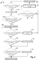
- FIG. 2 illustrates one embodiment of a control logic 200 that can be implemented in software stored on the controller 114 and used to operate the purge and pressurization system 100.
- the variable-speed fan 122 can be run at full speed (see 202) to begin pressurizing the container 102.
- Ambient pressure within the container 102 can be continuously or periodically detected using the pressure sensor 136 to determine if a minimum required pressure has been reached (see 204).
- reaching the required minimum pressure within the container 102 does not immediately result in the electronics 106 being powered. Rather, it can be desirable (or even required, depending on applicable regulations) to wait for a predetermined number of air exchanges to have occurred within the container 102 before powering the electronics 106.
- An air exchange is the process of pumping a volume of air through the container 102 that is equal to the volume of the container itself, such that all of the air within the container is replaced.
- the container 102 can include at least one vent 103 that can allow air to escape from the container 102 at a predetermined rate. Accordingly, a simple timer can determine the number of air exchanges that have taken place given the known volume of the container 102 and flow rate of the at least one vent 103.
- reaching the minimum required pressure within the container 102 can initiate an air exchange timer (see 206).
- the timer can be calibrated to allow for any number of predetermined air exchanges before power is selectively applied to the electronics 106 by the controller 114 (see 208, 210). In some embodiments, for example, the timer can be calibrated to allow for four complete air exchanges before power is applied. However, if the detected pressure falls below the minimum required pressure at any time during the air exchanges (see 212), power is not applied to the electronics 106, the air exchange timer is reset (see 214), and the fan 122 is again run at full speed until the minimum pressure is achieved.
- the air exchanges are completed successfully and the minimum pressure is maintained, there can be reasonable certainty that no explosive vapors are present within the container 102 and power can be applied to the electronics 106 (see 210). After this occurs, the pressure can continually or periodically be detected (see 216) using the pressure sensor 136 and, should the detected pressure fall below the minimum required pressure, the controller 114 can disconnect power to the electronics 106 (see 218).
- the temperature within the container 102 can be continuously or periodically detected and compared to a predetermined minimum temperature (see 220).
- the predetermined minimum temperature can be, for example, a minimum operating temperature for the electronics 106.
- severe cold temperatures can negatively affect the operation of certain components, such as displays and receipt printers, that are commonly used in fuel dispenser payment terminals. As a result, it can be desirable to keep these elements above a certain minimum temperature.
- the heating element 130 can be activated (see 222) to warm the air being introduced into the container 102 by the fan 122.
- the speed of the fan 122 can be continuously or periodically adjusted so as to maintain the detected pressure a certain level above the minimum required pressure.
- the speed of the fan 122 can be adjusted to maintain the detected pressure at a value between about 120% and about 150% of the minimum required pressure (see 224 and 226). Maintaining the pressure at this level can minimize the speed of the fan 122 and the volume of air forced into the container 102 while maintaining safe operation of the system 100.
- Minimizing the airflow through the container 102 in this manner can correspondingly minimize any negative side effects of introducing air that is possibly cold, damp, or dirty into the container 102.
- conditioning the air e.g., by heating it with the heating element 130 or filtering debris using the particulate air filter 132, can further reduce the risk of damaging or detrimentally affecting the operation of electronics 106 within the container 102. All of this can be accomplished while still accounting for changes in pressure outside the container 102 due to temperature, wind speed, etc.
- the fan 122 can be operated at an optimum (i.e., minimum) speed necessary to maintain the required minimum pressure within the container 102, regardless of environmental conditions outside the container. Operating the fan 122 in this manner can also save energy and reduce wear and tear on the mechanical components of the system.
- FIGS. 3-4 illustrate one embodiment of a purge and pressurization system implemented in connection with a fuel dispenser, such as a compressed natural gas (CNG) or liquefied natural gas (LNG) dispenser.
- a fuel dispenser such as a compressed natural gas (CNG) or liquefied natural gas (LNG) dispenser.
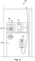
- FIG. 3 illustrates a front view of one embodiment of a dispenser 300 that includes a hydraulic chassis 302 containing fuel dispensing equipment to deliver fuel into a portable container (e.g., a vehicle's holding tank) through a nozzle 304.
- the dispenser 300 also includes an electronic head 306 disposed above the hydraulic chassis 302.
- the electronic head 306 houses any of a number of electronic components, such as a keypad 308, a display 310, and a receipt printer 312 that make up a payment terminal.
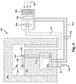
- FIG. 4 illustrates the dispenser 300 in cross-section with its hydraulic chassis 302 and electronic head 306 that includes at least one vent 401 (e.g., a dedicated vent or an opening used for another purpose, such as the receipt printer 312), as well as the surrounding classified hazardous area 402. Also shown in FIG. 4 is a variable-speed fan 404, a heating element 406, and a particulate air filter 408 located adjacent to one another outside the hazardous area 402. These components are similar to those described above in connection with FIG. 1 . As with the embodiment shown in FIG.
- the fan 404, heating element 406, and air filter 408 can be air-coupled to the electronic head 306 via a pipe 410, which in the illustrated embodiment extends below ground and through the hydraulic chassis 302 before entering the electronic head 306.
- Control lines 412 can extend through a potted conduit 414 to connect the fan 404 and the heating element 406 with a controller 416 that is disposed within an explosion-proof box 418 within the hydraulic chassis 302. Similar to the explosion-proof box described above, in certain embodiments the box 418 can be positioned within the electronic head 306, outside the dispenser 300, or even outside the hazardous area 402.
- the controller 416 can itself be an intrinsically safe component, and the explosion-proof box 418 can be omitted.
- the controller 416 can be coupled to incoming power lines 420 that extend through a potted conduit 421, and can selectively energize electronic components 403 (e.g., keypad 308, display 310, and receipt printer 312) via a transmission line 422 that extends through a potted conduit 423 from the controller 416 to the electronic head 306.
- electronic components 403 e.g., keypad 308, display 310, and receipt printer 312
- a pressure sensor 424 and a temperature sensor 426 can be positioned within the electronic head 306 and coupled to the controller 416 to provide feedback input for controlling any of the fan 404 and the heating element 406, as described above.
- the pressure sensor 424 and the temperature sensor 426 can be any of a variety of sensors known in the art.
- these sensors can be positioned at a variety of locations within the electronic head 306, but should be positioned so as to detect an ambient pressure or temperature within the electronic head 306, not the potted conduit 423. This is because the reduced volume of the conduit 423 can result in a higher pressure and/or temperature being detected than is actually present within the electronic head 306.
- variable speed fan 404, heating element 406, and particulate air filter 408 disposed near air intake 428 can be positioned any distance from the dispenser 300 outside of the hazardous area 402. However, in certain embodiments, it can be advantageous to position these components as close to the dispenser 300 as possible (while remaining outside the hazardous area 402) in order to reduce the resistance experienced by the fan 404 in forcing clean air into the electronic head 306.
Landscapes
- Engineering & Computer Science (AREA)
- Physics & Mathematics (AREA)
- Health & Medical Sciences (AREA)
- Public Health (AREA)
- Business, Economics & Management (AREA)
- Emergency Management (AREA)
- General Physics & Mathematics (AREA)
- Fluid Mechanics (AREA)
- Mechanical Engineering (AREA)
- Automation & Control Theory (AREA)
- Operations Research (AREA)
- Filling Or Discharging Of Gas Storage Vessels (AREA)
- Cooling Or The Like Of Electrical Apparatus (AREA)
Description
- The present invention relates to air purge and pressurization systems used to allow operation of electronics in hazardous environments.
- Environments classified as hazardous due to risk of explosion or fire are common at many commercial and industrial sites. Areas involving fuel-dispensing equipment, for example, are classified as hazardous due to the types of products handled by these dispensers. A well-defined classification system for such hazardous environments has been developed, and equipment can be rated to operate in various environment classes. Areas where ignitable concentrations of flammable gases, flammable liquid-produced vapors, or combustible liquid-produced vapors can exist under normal operating conditions and/or where hazard is caused by frequent maintenance or repair work or frequent equipment failure are classified as Class I, Division 1. The inside of the hydraulic cabinet of a gasoline dispenser would an example of such a classification. Electronics used are required to be "explosion proof' or "intrinsically safe," meaning that they cannot create a spark capable of ignition even in the case of a fault of electronics.
- Areas where ignitable concentrations of flammable gases, flammable liquid-produced vapors, or combustible liquid-produced vapors are not normally present, but may exist due to an accidental rupture or breakdown, are classified as Class I, Division 2. This typically includes areas adjacent to Class I, Division 1 areas. The immediate area around a dispenser would be an example of such an area. Electronics used in this area are required to not be able to produce a spark capable of ignition under normal operating conditions.
- The type of fuel dispensed determines the classification of the hazardous zones in and around the dispenser. Fuels with vapors that are heavier than air differ from those with properties that are lighter than air and thus create different zones.
- Electronics must be designed to meet the requirements of the zone in which they will reside. In some cases this can be expensive (e.g., the design of Intrinsically Safe Barriers or Explosion-proof boxes) and, in still other cases, it may be that the electronics cannot be designed or protected so as to perform the desired function while meeting the zone requirements (e.g., the design of a receipt printer to be used in a Class I, Division 1 area).
- In certain cases it can be desirable to use general-purpose electronics that are not rated for operation in any classified hazardous environment. In such cases, a technique for permitting the use of insufficiently rated electronics is to provide a purge/pressurization system to create a safe environment within a portion of the hazardous environment. Purge systems operate by drawing air from a source outside the hazardous environment and forcing it into a container within the hazardous environment so as to create a positive pressure within the container. So long as the positive pressure is maintained, vapors from the hazardous environment will not be able to enter the container and power can be safely supplied to the electronics.
US 2002/0196605 discloses a purge system for developing a positive pressure within an enclosure, with sufficient air flow to cool electrical components. Air is discharged into the enclosure by a blower in order to provide a positive pressure within the enclosure. The discharged air strikes a baffle for distributing the blowing air. - Purge systems are not without drawbacks, however. For example, the air drawn into the system from outside the hazardous environment can include dirt or moisture that can be harmful to the electronic components (e.g., printed circuit boards, displays, etc.) disposed within the purged environment. Furthermore, the temperature of the air introduced into the purged environment can be unregulated and can also negatively affect operation of certain components (e.g., displays, receipt printers, etc.).
- In addition, the flow rate of purge systems can be fixed and therefore not adaptable to varying ambient conditions such as relative humidity, temperature, wind speed, etc. Indeed, prior art purge systems are commonly designed to operate at a single flow rate that is calculated to maintain the required pressure under a "worst-case scenario" where, e.g., leaks have developed in the purged container, extreme temperatures are experienced, etc. As a result of the fact that the flow rate is fixed and higher than normally required, the systems are regularly producing a greater volume of airflow than is necessary.
- The greater volume of airflow can produce a number of detrimental effects. At the outset, continually running the purge system at the "worst-case scenario" flow rate wastes energy and inflicts undue wear and tear on the driving fan and other components of the system. In addition, if the supplied air is carrying dirt or moisture, a greater amount of each of these contaminants is being introduced than is necessary. Similarly, the temperature of the air being introduced can be detrimental to operation of the electronics within the purged environment, e.g., when frigid air is forced into a container during winter months when heating of the container would be desirable.
- Accordingly, there is a need in the art for improved purge and pressurization systems that allow for the use of electronic components in a hazardous environment. In particular, there is a need for such systems that can optimize the flow rate of air into the purged environment and thereby minimize any negative side effects of system operation.
- The present invention addresses these needs by providing an air purge and pressurization system according to claim 1 and a method for powering electronic devices within an area classified as hazardous according to claim 10.
- As mentioned above, the teachings of the present invention can have particular utility in fuel dispensing applications. In one aspect, for example, a natural gas dispenser system can be provided that includes a hydraulic chassis configured to transfer natural gas into a portable container, and an electronic head coupled to the hydraulic chassis, where the electronic head defines an enclosed container housing at least one electronic component not rated for operation in a hazardous area surrounding the hydraulic chassis. The system can further include a pressure sensor disposed within the electronic head to detect a pressure therein, and a variable-speed fan located outside the hazardous area and configured to deliver air from outside the hazardous area into the container. The system can also include a controller rated for operation in the hazardous area that is coupled to the pressure sensor, the variable-speed fan, and the at least one electronic component disposed within the container. The controller can be configured to adjust a speed of the fan based on the detected pressure and selectively power the at least one electronic component if the detected pressure is above a minimum pressure.
- The aspects and embodiments of the invention described above will be more fully understood from the following detailed description taken in conjunction with the accompanying drawings, in which:
-
FIG. 1 is an illustration of one embodiment of a purge system according to the teachings of the present invention; -
FIG. 2 is a flow chart illustrating one embodiment of a control logic for a purge system; -
FIG. 3 is a front view illustration of one embodiment of a fuel dispenser; and -
FIG. 4 is a cross-sectional view illustration of the natural gas dispenser ofFIG. 3 including a purge system. - The present invention is generally directed to air purge and pressurization systems that can be used to create a safe, unclassified area within an environment classified as hazardous due to the presence of explosive gases. Such systems can be used, for example, to protect and allow for the use of electronic components that are otherwise not rated for use in the hazardous environment. Disclosed herein are novel purge and pressurization systems that utilize a feedback loop (provided using, e.g., a pressure sensor within the volume being protected) to control a variable speed fan that provides inert airflow for purging and/or pressurization. By using detected pressure within the protected volume as a feedback control input, the systems described herein can effectively minimize the volume of air being forced into the protected volume. Further, the flow rate of inert air can change over time depending on changes in ambient pressure, temperature, humidity, wind speed, etc., thereby allowing the system to run at an optimum level in any condition. This is in marked contrast to prior art systems that utilize fixed-speed fans and therefore must always operate at a speed that is sufficient to provide pressurization under the worst possible conditions.
-
FIG. 1 illustrates one embodiment of a purge and pressurization system 100 (sometimes known in the art as an "X-type purge" or "X Purge" system) according to the teachings of the present invention. The system generally includes acontainer 102 that is to be protected from a surrounding hazardous environment 104. Thecontainer 102 can have at least one vent 103 that allows air to escape into the surrounding area at a known rate. Thecontainer 102 can also house any of a variety of electronic components 106 that can be general-purpose in nature, i.e., not rated for use in any type of classified environment, or insufficiently-rated for the type of hazardous environment 104 that is present (e.g., a Class I, Division II-rated payment terminal being disposed in a Class I, Division I environment). The electronics 106 can be coupled to an electrical power delivery line 108 that can be selectively energized to provide power to the electronics. The power line 108 can extend out of thecontainer 102 through, for example, a potted (i.e., sealed) conduit 110 and into an explosion-proof box 112 where it can connect to a controller 114. The controller 114 can be coupled to incoming power lines 116, 118 that extend into the explosion-proof box 112 from an underground location through, for example, apotted conduit 120. - The
system 100 further includes a variable-speed fan 122 located outside the hazardous area 104 and air-coupled to thecontainer 102 via a pipe 124. Thefan 122 can be located any distance away from thecontainer 102, but should be positioned as close as possible to the container outside the hazardous area 104. This can minimize the resistance experienced by the fan in forcing air into thecontainer 102. In some embodiments, the position of thefan 122 can be dictated by how far the classified hazardous area 104 extends from thecontainer 102. - The
fan 122 can also be coupled to the controller 114 via control lines 126 that extend through apotted conduit 128 between the fan and the controller. The controller 114 can regulate the operating speed of thefan 122 via the control lines 126, as discussed in more detail below. Also disposed adjacent to thefan 122 outside of the hazardous area 104 can be a heating element 130 and a particulate air filter 132. The heating element 130 can be any of a variety of heating elements known in the art, and the controller 114 can manage activation of the heating element using the control lines 126, similar to the regulated operation of thefan 122. The particulate filter 132 can similarly be any of a variety of known air filters, and can be disposed adjacent to an air intake 134 so as to remove dirt and other debris from the air before it is exposed to the heating element 130,fan 122, or electronics 106. In other embodiments, it can be possible to place the filter 132 at a different location because the filter can be a passive (i.e., non-electrical) element that can operate within the hazardous area 104. Accordingly, in certain embodiments, the filter 132 can be positioned within the pipe 124, e.g., at the interface between the pipe and thecontainer 102, etc. - The purge and
pressurization system 100 can also include one or more sensors disposed within thecontainer 102 and configured to provide feedback to the controller 114 that can be used to adjust the operating speed of thefan 122. In some embodiments, apressure sensor 136 can be disposed within thecontainer 102 and coupled to the controller 114. Thepressure sensor 136 can detect ambient air pressure within the container and can be used to determine when a set minimum required pressure has been reached within thecontainer 102. Thepressure sensor 136 can be any of a variety of pressure sensors known in the art. - In certain embodiments, the
container 102 can also include a temperature sensor 138 that is coupled to the controller 114 and configured to detect an ambient temperature within thecontainer 102. Such a sensor can be utilized, for example, to provide feedback to the controller 114 that can be used to selectively activate the heating element 130. The temperature sensor 138 can be any of a variety of temperature sensors known in the art. - As mentioned above, the air purge and
pressurization system 100 can be used to create an unclassified environment within thecontainer 102 that allows for operation of electronic components 106 that are insufficiently rated for use in the surrounding hazardous area 104. In general, thepressure sensor 136 can be used to detect when ambient pressure within thecontainer 102 reaches a predetermined minimum level, and to ensure that the pressure does not drop below the minimum required level at any time thereafter. So long as this remains true, power can be selectively applied to the electronics 106. If, however, the detected pressure should ever drop below the minimum required level, the controller 114 can cut power to the electronics 106 to ensure that no explosion occurs. Note that power can be continuously applied to the controller 114 because it is disposed in an explosion-proof box 112. Moreover, while the explosion-proof box 112 and controller 114 are shown outside of thecontainer 102 inFIG. 1 , in certain embodiments these components can be disposed elsewhere, such as inside thecontainer 102 or outside of the hazardous area 104 entirely. -
FIG. 2 illustrates one embodiment of acontrol logic 200 that can be implemented in software stored on the controller 114 and used to operate the purge andpressurization system 100. When thesystem 100 is first activated, the variable-speed fan 122 can be run at full speed (see 202) to begin pressurizing thecontainer 102. Ambient pressure within thecontainer 102 can be continuously or periodically detected using thepressure sensor 136 to determine if a minimum required pressure has been reached (see 204). - In certain embodiments, reaching the required minimum pressure within the
container 102 does not immediately result in the electronics 106 being powered. Rather, it can be desirable (or even required, depending on applicable regulations) to wait for a predetermined number of air exchanges to have occurred within thecontainer 102 before powering the electronics 106. An air exchange is the process of pumping a volume of air through thecontainer 102 that is equal to the volume of the container itself, such that all of the air within the container is replaced. As mentioned above, thecontainer 102 can include at least one vent 103 that can allow air to escape from thecontainer 102 at a predetermined rate. Accordingly, a simple timer can determine the number of air exchanges that have taken place given the known volume of thecontainer 102 and flow rate of the at least one vent 103. - In some embodiments, then, reaching the minimum required pressure within the
container 102 can initiate an air exchange timer (see 206). The timer can be calibrated to allow for any number of predetermined air exchanges before power is selectively applied to the electronics 106 by the controller 114 (see 208, 210). In some embodiments, for example, the timer can be calibrated to allow for four complete air exchanges before power is applied. However, if the detected pressure falls below the minimum required pressure at any time during the air exchanges (see 212), power is not applied to the electronics 106, the air exchange timer is reset (see 214), and thefan 122 is again run at full speed until the minimum pressure is achieved. - On the other hand, if the air exchanges are completed successfully and the minimum pressure is maintained, there can be reasonable certainty that no explosive vapors are present within the
container 102 and power can be applied to the electronics 106 (see 210). After this occurs, the pressure can continually or periodically be detected (see 216) using thepressure sensor 136 and, should the detected pressure fall below the minimum required pressure, the controller 114 can disconnect power to the electronics 106 (see 218). - In addition, in embodiments having a temperature sensor 138 and heating element 130, the temperature within the
container 102 can be continuously or periodically detected and compared to a predetermined minimum temperature (see 220). The predetermined minimum temperature can be, for example, a minimum operating temperature for the electronics 106. By way of further example, severe cold temperatures can negatively affect the operation of certain components, such as displays and receipt printers, that are commonly used in fuel dispenser payment terminals. As a result, it can be desirable to keep these elements above a certain minimum temperature. In such an embodiment, if the detected temperature is below the predetermined minimum temperature, the heating element 130 can be activated (see 222) to warm the air being introduced into thecontainer 102 by thefan 122. - Still further, once the minimum required pressure has been achieved in the
container 102 and the predetermined number of air exchanges have been completed, the speed of thefan 122 can be continuously or periodically adjusted so as to maintain the detected pressure a certain level above the minimum required pressure. For example, in some embodiments the speed of thefan 122 can be adjusted to maintain the detected pressure at a value between about 120% and about 150% of the minimum required pressure (see 224 and 226). Maintaining the pressure at this level can minimize the speed of thefan 122 and the volume of air forced into thecontainer 102 while maintaining safe operation of thesystem 100. - Minimizing the airflow through the
container 102 in this manner can correspondingly minimize any negative side effects of introducing air that is possibly cold, damp, or dirty into thecontainer 102. Moreover, conditioning the air, e.g., by heating it with the heating element 130 or filtering debris using the particulate air filter 132, can further reduce the risk of damaging or detrimentally affecting the operation of electronics 106 within thecontainer 102. All of this can be accomplished while still accounting for changes in pressure outside thecontainer 102 due to temperature, wind speed, etc. In other words, thefan 122 can be operated at an optimum (i.e., minimum) speed necessary to maintain the required minimum pressure within thecontainer 102, regardless of environmental conditions outside the container. Operating thefan 122 in this manner can also save energy and reduce wear and tear on the mechanical components of the system. - As mentioned above, the systems and methods described herein can have particular utility in fuel dispensing applications, though they are in no way limited to use in this field.
FIGS. 3-4 illustrate one embodiment of a purge and pressurization system implemented in connection with a fuel dispenser, such as a compressed natural gas (CNG) or liquefied natural gas (LNG) dispenser. In particular,FIG. 3 illustrates a front view of one embodiment of adispenser 300 that includes ahydraulic chassis 302 containing fuel dispensing equipment to deliver fuel into a portable container (e.g., a vehicle's holding tank) through anozzle 304. Thedispenser 300 also includes anelectronic head 306 disposed above thehydraulic chassis 302. Theelectronic head 306 houses any of a number of electronic components, such as akeypad 308, a display 310, and areceipt printer 312 that make up a payment terminal. -
FIG. 4 illustrates thedispenser 300 in cross-section with itshydraulic chassis 302 andelectronic head 306 that includes at least one vent 401 (e.g., a dedicated vent or an opening used for another purpose, such as the receipt printer 312), as well as the surrounding classifiedhazardous area 402. Also shown inFIG. 4 is a variable-speed fan 404, aheating element 406, and aparticulate air filter 408 located adjacent to one another outside thehazardous area 402. These components are similar to those described above in connection withFIG. 1 . As with the embodiment shown inFIG. 1 , thefan 404,heating element 406, andair filter 408 can be air-coupled to theelectronic head 306 via apipe 410, which in the illustrated embodiment extends below ground and through thehydraulic chassis 302 before entering theelectronic head 306.Control lines 412 can extend through apotted conduit 414 to connect thefan 404 and theheating element 406 with acontroller 416 that is disposed within an explosion-proof box 418 within thehydraulic chassis 302. Similar to the explosion-proof box described above, in certain embodiments thebox 418 can be positioned within theelectronic head 306, outside thedispenser 300, or even outside thehazardous area 402. Moreover, in some embodiments thecontroller 416 can itself be an intrinsically safe component, and the explosion-proof box 418 can be omitted. - The
controller 416 can be coupled toincoming power lines 420 that extend through apotted conduit 421, and can selectively energize electronic components 403 (e.g.,keypad 308, display 310, and receipt printer 312) via atransmission line 422 that extends through a potted conduit 423 from thecontroller 416 to theelectronic head 306. In addition, a pressure sensor 424 and atemperature sensor 426 can be positioned within theelectronic head 306 and coupled to thecontroller 416 to provide feedback input for controlling any of thefan 404 and theheating element 406, as described above. - Similar to the pressure and temperature sensors described in connection with
FIG. 1 , the pressure sensor 424 and thetemperature sensor 426 can be any of a variety of sensors known in the art. In addition, these sensors can be positioned at a variety of locations within theelectronic head 306, but should be positioned so as to detect an ambient pressure or temperature within theelectronic head 306, not the potted conduit 423. This is because the reduced volume of the conduit 423 can result in a higher pressure and/or temperature being detected than is actually present within theelectronic head 306. - Furthermore, the
variable speed fan 404,heating element 406, andparticulate air filter 408 disposed nearair intake 428 can be positioned any distance from thedispenser 300 outside of thehazardous area 402. However, in certain embodiments, it can be advantageous to position these components as close to thedispenser 300 as possible (while remaining outside the hazardous area 402) in order to reduce the resistance experienced by thefan 404 in forcing clean air into theelectronic head 306.
Claims (15)
- An air purge and pressurization system (100), comprising:an enclosed container (102) located in an area (104, 402) classified as hazardous;a controller (114, 416) rated for operation within the hazardous area (104, 402);a pressure sensor (136, 424) located within the container (102) and coupled to the controller (114, 416);at least one electrically powered component (106, 403) disposed within the container (102);characterized in thatthe system further comprises a variable-speed fan (122, 404) located outside the hazardous area (104, 402) and coupled to the controller (114, 416), the fan (122, 404) being configured to force air from outside the hazardous area (104, 402) into the container (102); andwherein the controller (114, 416) is configured to monitor an air pressure detected by the pressure sensor (136, 424) and variably control a speed of the fan (122, 404) to maintain the detected pressure above a minimum pressure and to selectively power the at least one electrically powered component (106, 403) if the detected pressure is above the minimum pressure.
- The system (100) of claim 1, wherein the at least one electrically powered component (106, 403) is not rated for operation in the hazardous area (104, 402).
- The system (100) of claim 1, wherein the controller (114, 416) is further configured to wait for a predetermined number of complete air exchanges to take place within the container (102) after the detected pressure surpasses the minimum pressure and before powering the at least one electrically powered component (106, 403).
- The system (100) of claim 1, wherein the container (102) includes at least one vent (103, 401) to allow air within the container (102) to escape.
- The system of claim 1, wherein the controller (114, 416) is disposed outside the container (102).
- The system of claim 1, wherein the controller (114, 416) is disposed within the container (102).
- The system (100) of claim 1, further comprising a temperature sensor (138, 426) located within the container (102) and coupled to the controller (114, 416), wherein the controller (114, 416) is further configured to vary the speed of the fan (122, 404) based on both the detected air pressure and a temperature detected by the temperature sensor (138, 426).
- The system (100) of claim 7, further comprising a heating element (130, 406) located outside the hazardous area (104, 402) adjacent to the fan (122, 404), wherein the controller (114, 416) is further configured to selectively activate the heating element (130, 406) to maintain the detected temperature above a minimum temperature.
- The system (100) of claim 1, further comprising a particulate filter (132, 408) air-coupled to the container (102) such that air forced into the container (100) is first passed through the particulate filter (132, 408).
- A method for powering electronic devices within an area (104, 402) classified as hazardous, comprising:detecting a pressure within an enclosed container (102) located in the hazardous area (104, 402) using a pressure sensor (136, 424);characterized byvariably controlling a speed of a fan (122, 404) located outside the hazardous area (104, 402) and air-coupled to the container (102) based on the detected pressure to achieve a minimum pressure within the container (102); andselectively applying power to an electronic device (106, 403) disposed within the container (102) if the detected pressure is above the minimum pressure.
- The method of claim 10, wherein the speed of the fan (122, 404) is controlled to maintain the detected pressure within a range of about 120% to about 150% of the minimum pressure.
- A natural gas dispenser system (300), comprising:a hydraulic chassis (302) configured to transfer natural gas into a portable container; andan air purge and pressurization system (100) according to any one of claims 1-9, wherein the enclosed container (102) is coupled to the hydraulic chassis (302).
- The system (300) according to claim 12, wherein the enclosed container (102) is an electronic head (306) defining the enclosed container (102) housing the at least one electrically powered component (106, 403), wherein the at least one electrically powered component (106, 403) is not rated for operation in a hazardous area (104, 402) surrounding the hydraulic chassis (302).
- The system (300) of claim 13, wherein the electronic head (306) includes at least one vent (401) to allow air to escape therefrom, and wherein the controller (114, 416) is further configured to wait for a predetermined number of complete air exchanges to take place within the electronic head (306) after the detected pressure surpasses the minimum pressure and before selectively powering the at least one electrically powered component (106, 403).
- The system (300) of claim 13, further comprising a particulate filter (408) air-coupled to the electronic head (306) such that air forced into the electronic head (306) is first passed through the particulate filter (408).
Applications Claiming Priority (2)
| Application Number | Priority Date | Filing Date | Title |
|---|---|---|---|
| US14/270,282 US10646734B2 (en) | 2014-05-05 | 2014-05-05 | Purge and pressurization system with feedback control |
| PCT/US2015/028782 WO2015171455A1 (en) | 2014-05-05 | 2015-05-01 | Purge and pressurization system with feedback control |
Publications (2)
| Publication Number | Publication Date |
|---|---|
| EP3140711A1 EP3140711A1 (en) | 2017-03-15 |
| EP3140711B1 true EP3140711B1 (en) | 2021-03-10 |
Family
ID=53277030
Family Applications (1)
| Application Number | Title | Priority Date | Filing Date |
|---|---|---|---|
| EP15726763.4A Active EP3140711B1 (en) | 2014-05-05 | 2015-05-01 | Purge and pressurization system with feedback control |
Country Status (6)
| Country | Link |
|---|---|
| US (1) | US10646734B2 (en) |
| EP (1) | EP3140711B1 (en) |
| CA (1) | CA2946316C (en) |
| ES (1) | ES2869373T3 (en) |
| PT (1) | PT3140711T (en) |
| WO (1) | WO2015171455A1 (en) |
Cited By (1)
| Publication number | Priority date | Publication date | Assignee | Title |
|---|---|---|---|---|
| WO2025201653A1 (en) * | 2024-03-28 | 2025-10-02 | Dover Fueling Solutions Uk Limited | A method for providing a climate zone in a fuel dispenser and a fuel dispenser |
Families Citing this family (6)
| Publication number | Priority date | Publication date | Assignee | Title |
|---|---|---|---|---|
| GB0816310D0 (en) | 2008-09-05 | 2008-10-15 | Mtt Technologies Ltd | Filter assembly |
| US10646734B2 (en) * | 2014-05-05 | 2020-05-12 | Wayne Fueling Systems Sweden Ab | Purge and pressurization system with feedback control |
| JP2017538038A (en) * | 2014-11-21 | 2017-12-21 | レニショウ パブリック リミテッド カンパニーRenishaw Public Limited Company | Additive manufacturing apparatus and method |
| US11105526B1 (en) | 2017-09-29 | 2021-08-31 | Integrated Global Services, Inc. | Safety shutdown systems and methods for LNG, crude oil refineries, petrochemical plants, and other facilities |
| EP3912688A1 (en) * | 2020-05-19 | 2021-11-24 | L'air Liquide, Société Anonyme Pour L'Étude Et L'exploitation Des Procédés Georges Claude | Secure inerting device |
| US20230119975A1 (en) * | 2021-10-19 | 2023-04-20 | Pony Ai Inc. | System and method for regulating a sensor enclosure |
Family Cites Families (76)
| Publication number | Priority date | Publication date | Assignee | Title |
|---|---|---|---|---|
| US2311374A (en) * | 1938-11-01 | 1943-02-16 | American District Telegraph Co | Automatic fire control system for ventilating or air conditioning systems |
| US4298955A (en) * | 1976-04-01 | 1981-11-03 | The Insurance Technical Bureau | Method of and apparatus for the detection and analysis of hazards |
| US4169225A (en) * | 1978-04-24 | 1979-09-25 | Templeton Coal Company | Electric heating apparatus with automatic purging system |
| US4211251A (en) * | 1978-04-24 | 1980-07-08 | Templeton Coal Co., Inc. | Automatic purging system |
| US4616694A (en) * | 1984-10-22 | 1986-10-14 | Hsieh Shih Yung | Fireproof cabinet system for electronic equipment |
| DE3532820A1 (en) * | 1985-09-13 | 1987-03-26 | Gas & Wasserleitungsgeschaeft | DEVICE FOR UNIFORM HEATING OF SPACES |
| US4802502A (en) * | 1987-02-20 | 1989-02-07 | Geolograph Pioneer, Inc. | Purge air control system |
| US4972866A (en) * | 1989-03-03 | 1990-11-27 | Lt Industries | Purge control module |
| US4986445A (en) * | 1989-12-04 | 1991-01-22 | Gilbarco Inc. | Gasoline dispenser with valve control through an air gap |
| US5101710A (en) | 1990-05-14 | 1992-04-07 | Bebco Industries, Inc. | Control apparatus or system for purged and pressurized enclosures for electrical equipment |
| US5189392A (en) * | 1991-06-24 | 1993-02-23 | Kass Carl E | Heating system shut-off system using detector and existing safety switch or fuel valve |
| US5720658A (en) * | 1992-02-11 | 1998-02-24 | Belusa; Manfred L. | Space pressurization control system for high containment laboratories |
| US5215499A (en) * | 1992-02-19 | 1993-06-01 | Hale Fire Pump Company | Positive pressure safety system |
| US5228306A (en) * | 1992-04-20 | 1993-07-20 | Norm Pacific Automation Corp. | Apparatus for controlling air-exchange and pressure and detecting airtight conditions in air-conditioned room |
| US5791983A (en) * | 1995-10-20 | 1998-08-11 | Healthy Buildings International | Demand ventilation system |
| US6101459A (en) * | 1997-08-15 | 2000-08-08 | Compaq Computer Corporation | System and associated method for cooling components within a computer system |
| US6119715A (en) * | 1997-09-30 | 2000-09-19 | Russell; Larry R. | Automated pneumatic purger |
| WO1999047864A1 (en) * | 1998-03-16 | 1999-09-23 | Asyst Technologies, Inc. | Intelligent minienvironment |
| US6218951B1 (en) * | 1999-01-29 | 2001-04-17 | Western Technology | Safety circuit |
| US6192922B1 (en) * | 1999-06-01 | 2001-02-27 | Synetics Solutions Inc. | Airflow control valve for a clean room |
| FR2805601B1 (en) * | 2000-02-29 | 2002-06-07 | Aldes Aeraulique | SELF-DRIVING VENTILATION GROUP WITH ELECTRONIC CONTROL |
| US6481635B2 (en) * | 2000-07-21 | 2002-11-19 | Gun Valley Temperature Controls Llc | Environmental control method |
| US6423118B1 (en) * | 2000-09-05 | 2002-07-23 | General Electric Company | Methods and systems for controlling air filtration systems |
| US6402613B1 (en) * | 2001-02-21 | 2002-06-11 | David B. Teagle | Portable environmental control system |
| US6590769B2 (en) | 2001-06-22 | 2003-07-08 | Hutchison-Hayes International, Inc. | Purge and cooling system for enclosure for hazardous environment |
| US6783054B1 (en) * | 2002-05-20 | 2004-08-31 | Clyde W. Pregeant, Jr. | System for controllably conducting welding operations adjacent flammable materials and method of welding adjacent flammable materials |
| US6725132B2 (en) * | 2002-06-20 | 2004-04-20 | Minebea Co., Ltd. | Intelligent cooling fan |
| NO317999B3 (en) * | 2002-06-28 | 2010-07-05 | Sts Gruppen As | Device for securing the operation of a habitat |
| US6643130B1 (en) * | 2002-07-08 | 2003-11-04 | Demarchis John A. | Wash down filtered fan apparatus |
| US6681814B1 (en) | 2002-07-22 | 2004-01-27 | Gilbarco Inc. | Hazardous area power interlock |
| US6945456B2 (en) * | 2002-11-25 | 2005-09-20 | Diebold Self-Service Systems A Division Of Diebold, Incorporated | Automated banking machine including temperature controlled housing |
| US7518484B2 (en) * | 2003-03-13 | 2009-04-14 | Alford Safety Services, Inc. | Enclosure system allowing for hot work within the vicinity of flammable and combustible material |
| US7091848B2 (en) * | 2003-03-13 | 2006-08-15 | Alford Safety Services, Inc. | Enclosure system for hot work within the vicinity of flammable or combustible material |
| US7481234B1 (en) * | 2003-03-27 | 2009-01-27 | Gustafson Martin K | Bio-hazard attack family survival dome |
| US7187529B2 (en) * | 2003-04-30 | 2007-03-06 | Eaton Corporation | Apparatus and method for detecting a gas associated with a glowing contact and interrupting a power circuit |
| US7066091B2 (en) * | 2003-06-16 | 2006-06-27 | R.R. Donnelley & Sons Company | Methods and apparatus for controlling impurity levels in an enclosed printing press environment |
| US7036559B2 (en) * | 2003-07-08 | 2006-05-02 | Daniel Stanimirovic | Fully articulated and comprehensive air and fluid distribution, metering, and control method and apparatus for primary movers, heat exchangers, and terminal flow devices |
| US20050108996A1 (en) * | 2003-11-26 | 2005-05-26 | Latham Steven R. | Filter system for an electronic equipment enclosure |
| CN1913948A (en) * | 2004-02-03 | 2007-02-14 | 日本电气株式会社 | Closed type device with heat radiating structure, casing used for the device, and composite sheet |
| JP2006321041A (en) * | 2005-04-20 | 2006-11-30 | Yaskawa Electric Corp | Internal pressure explosion-proof system |
| US7484668B1 (en) * | 2005-10-03 | 2009-02-03 | Building Protection Systems, Inc. | Building protection system and method |
| US7232347B1 (en) * | 2006-01-06 | 2007-06-19 | Moore Boyd B | Seal for confined electrical conductor cable |
| JP3947553B1 (en) * | 2006-03-31 | 2007-07-25 | 株式会社日立コミュニケーションテクノロジー | Electronic equipment |
| SG136834A1 (en) * | 2006-04-28 | 2007-11-29 | Kyodo Allied Ind Ltd | A method and apparatus for maintaining air characteristics in an air ventilated facility using fan filter units |
| CA2653808C (en) * | 2006-06-01 | 2014-10-14 | Exaflop Llc | Controlled warm air capture |
| US7726186B2 (en) * | 2006-07-19 | 2010-06-01 | Degree Controls, Inc. | Airflow sensor for filter blockage detection |
| JP2008032335A (en) * | 2006-07-31 | 2008-02-14 | Hitachi High-Technologies Corp | Mini-environment device, inspection device, manufacturing device, and space cleaning method |
| US7405358B2 (en) * | 2006-10-17 | 2008-07-29 | Quick Connectors, Inc | Splice for down hole electrical submersible pump cable |
| WO2008097947A2 (en) * | 2007-02-05 | 2008-08-14 | Quick Connectors Inc. | Down hole electrical connector for combating rapid decompression |
| JP4867727B2 (en) * | 2007-03-13 | 2012-02-01 | パナソニック株式会社 | Cooling system |
| US8408356B2 (en) * | 2007-04-17 | 2013-04-02 | Fujitsu Limited | Storage box for electronic apparatus |
| US20080311842A1 (en) * | 2007-06-15 | 2008-12-18 | Glacier Bay, Inc. | HVAC air distribution system |
| US20090020618A1 (en) * | 2007-07-16 | 2009-01-22 | Motorola, Inc. | System and method for environmental control of an enclosure |
| US20090045925A1 (en) * | 2007-08-17 | 2009-02-19 | Franklin Fueling Systems, Inc. | System, Apparatus, and Method for Communicating Sensor Information of a System Component that is Disposed in a Hazardous Location |
| EP2184140B1 (en) * | 2007-09-11 | 2012-04-18 | Kabushiki Kaisha Yaskawa Denki | Robot of internal pressure explosion-proof structure |
| US8668560B2 (en) * | 2007-09-27 | 2014-03-11 | Dresser, Inc. | Shielding electronic components from liquid |
| US9586807B2 (en) * | 2007-09-27 | 2017-03-07 | Wayne Fueling Systems Llc | Maintaining an operational temperature range |
| US20090134995A1 (en) * | 2007-11-26 | 2009-05-28 | Cinaruco International, S.A. | Workspace enclosure system with automatic shut-off |
| US8141374B2 (en) * | 2008-12-22 | 2012-03-27 | Amazon Technologies, Inc. | Multi-mode cooling system and method with evaporative cooling |
| TWI438340B (en) * | 2009-02-19 | 2014-05-21 | Delta Electronics Inc | Wind velocity measurement circuit capable of detecting the timing for replacing dustproof element |
| US8947249B1 (en) * | 2009-03-26 | 2015-02-03 | Safezone Safety Systems, LLC | Apparatus and method for conducting hot work |
| US8436277B2 (en) * | 2010-02-23 | 2013-05-07 | Louis J. Wardlaw | Automatic shutoff system and method for workspace enclosure environment |
| US8300410B2 (en) * | 2010-07-15 | 2012-10-30 | Io Data Centers, Llc | Apparatus and method for regulating various conditions affecting electronic equipment |
| TW201207597A (en) * | 2010-08-09 | 2012-02-16 | Hon Hai Prec Ind Co Ltd | Container data center and adjusting apparatus thereof |
| US8665591B2 (en) * | 2010-12-21 | 2014-03-04 | General Electric Company | Systems and methods to thermally manage electronic devices |
| TW201227242A (en) * | 2010-12-24 | 2012-07-01 | Hon Hai Prec Ind Co Ltd | Heat dissipation system and container using the same |
| JP5759808B2 (en) * | 2011-06-30 | 2015-08-05 | 株式会社東芝 | Air conditioning system and air conditioning control method for server room management |
| US8670870B1 (en) * | 2011-09-19 | 2014-03-11 | Englobal Corporation | Modular HVAC system for providing positive pressure to an interior of a positive pressure facility |
| US9326426B2 (en) * | 2011-10-05 | 2016-04-26 | Diversified Control, Inc. | Equipment enclosure with air diverter temperature control system |
| JP2015038904A (en) * | 2011-11-18 | 2015-02-26 | 株式会社東芝 | Information processing device and cooling fan control method |
| JP5932350B2 (en) * | 2012-01-18 | 2016-06-08 | 株式会社東芝 | Air conditioning apparatus and air conditioning control method |
| US9038441B2 (en) * | 2012-01-20 | 2015-05-26 | TLI Enterprises, Inc. | High speed helium leak detection system and method |
| US20130324027A1 (en) * | 2012-06-01 | 2013-12-05 | David Davis | Economizer hvac and control system |
| TW201515562A (en) * | 2013-10-04 | 2015-04-16 | Acer Inc | Temperature adjusting apparatus for server and method thereof |
| US9157670B2 (en) * | 2013-10-25 | 2015-10-13 | Kooltronic, Inc. | Hazardous location heat transfer unit |
| US10646734B2 (en) * | 2014-05-05 | 2020-05-12 | Wayne Fueling Systems Sweden Ab | Purge and pressurization system with feedback control |
-
2014
- 2014-05-05 US US14/270,282 patent/US10646734B2/en active Active
-
2015
- 2015-05-01 WO PCT/US2015/028782 patent/WO2015171455A1/en not_active Ceased
- 2015-05-01 EP EP15726763.4A patent/EP3140711B1/en active Active
- 2015-05-01 PT PT157267634T patent/PT3140711T/en unknown
- 2015-05-01 ES ES15726763T patent/ES2869373T3/en active Active
- 2015-05-01 CA CA2946316A patent/CA2946316C/en active Active
Non-Patent Citations (1)
| Title |
|---|
| None * |
Cited By (1)
| Publication number | Priority date | Publication date | Assignee | Title |
|---|---|---|---|---|
| WO2025201653A1 (en) * | 2024-03-28 | 2025-10-02 | Dover Fueling Solutions Uk Limited | A method for providing a climate zone in a fuel dispenser and a fuel dispenser |
Also Published As
| Publication number | Publication date |
|---|---|
| US10646734B2 (en) | 2020-05-12 |
| PT3140711T (en) | 2021-04-22 |
| US20150314152A1 (en) | 2015-11-05 |
| EP3140711A1 (en) | 2017-03-15 |
| CA2946316A1 (en) | 2015-11-12 |
| CA2946316C (en) | 2019-01-08 |
| WO2015171455A1 (en) | 2015-11-12 |
| ES2869373T3 (en) | 2021-10-25 |
Similar Documents
| Publication | Publication Date | Title |
|---|---|---|
| CA2946316C (en) | Purge and pressurization system with feedback control | |
| CN214957115U (en) | Safe explosion-proof container formula energy storage system | |
| US12390675B2 (en) | Flameless venting system | |
| US20080287050A1 (en) | Integrated Explosion Protection Apparatus For Supervision And Control Of Advanced Electrical Apparatuses | |
| CN205469912U (en) | Print powdered ink partial shipment dust exposion prevention protection system | |
| CN106841300A (en) | A kind of Combined industry dust explosion analog demenstration system | |
| US6526808B1 (en) | Smoke and clean air generating machine for detecting presence and location of leaks in a fluid system | |
| KR101992741B1 (en) | Purging controller for pressurized type anti-explosion | |
| CN202637777U (en) | Flame-insulation explosion-proof device and flame-insulation explosion-proof emergency system | |
| CN105659034A (en) | flow action check valve | |
| US12097537B2 (en) | Solvent containment and process interlocking system | |
| KR101440020B1 (en) | Leakage protection device | |
| US10601278B2 (en) | Protection system for an electrical machine | |
| CN103601164B (en) | Inert gas generating device | |
| KR20150046970A (en) | Gas turbine ventilation system and filter unit | |
| Module | Installation and Operating Manual | |
| Glickert et al. | Blow Down Air Knife System | |
| KR20200099296A (en) | Exhaust hood having wind speed sensing function | |
| EP3747560A1 (en) | Device and method for the pre-degassing of a fuel tank | |
| KR20170122093A (en) | Boiler | |
| Going et al. | Dust collector explosion prevention and control | |
| CN215195143U (en) | Monomer extinguishing device of charging cabinet | |
| US20250230905A1 (en) | Device for preventing accumulation of flammable fluid in manholes containing line valves | |
| US20260094514A1 (en) | Control panel and method for spark and explosion protection control | |
| CN212327897U (en) | Little amount of wind high concentration exhaust treatment system |
Legal Events
| Date | Code | Title | Description |
|---|---|---|---|
| STAA | Information on the status of an ep patent application or granted ep patent |
Free format text: STATUS: THE INTERNATIONAL PUBLICATION HAS BEEN MADE |
|
| PUAI | Public reference made under article 153(3) epc to a published international application that has entered the european phase |
Free format text: ORIGINAL CODE: 0009012 |
|
| STAA | Information on the status of an ep patent application or granted ep patent |
Free format text: STATUS: REQUEST FOR EXAMINATION WAS MADE |
|
| 17P | Request for examination filed |
Effective date: 20161118 |
|
| AK | Designated contracting states |
Kind code of ref document: A1 Designated state(s): AL AT BE BG CH CY CZ DE DK EE ES FI FR GB GR HR HU IE IS IT LI LT LU LV MC MK MT NL NO PL PT RO RS SE SI SK SM TR |
|
| AX | Request for extension of the european patent |
Extension state: BA ME |
|
| DAV | Request for validation of the european patent (deleted) | ||
| DAX | Request for extension of the european patent (deleted) | ||
| STAA | Information on the status of an ep patent application or granted ep patent |
Free format text: STATUS: EXAMINATION IS IN PROGRESS |
|
| 17Q | First examination report despatched |
Effective date: 20200103 |
|
| GRAP | Despatch of communication of intention to grant a patent |
Free format text: ORIGINAL CODE: EPIDOSNIGR1 |
|
| STAA | Information on the status of an ep patent application or granted ep patent |
Free format text: STATUS: GRANT OF PATENT IS INTENDED |
|
| RIC1 | Information provided on ipc code assigned before grant |
Ipc: B67D 7/32 20100101ALI20200923BHEP Ipc: G05D 16/20 20060101AFI20200923BHEP |
|
| INTG | Intention to grant announced |
Effective date: 20201008 |
|
| GRAS | Grant fee paid |
Free format text: ORIGINAL CODE: EPIDOSNIGR3 |
|
| GRAA | (expected) grant |
Free format text: ORIGINAL CODE: 0009210 |
|
| STAA | Information on the status of an ep patent application or granted ep patent |
Free format text: STATUS: THE PATENT HAS BEEN GRANTED |
|
| AK | Designated contracting states |
Kind code of ref document: B1 Designated state(s): AL AT BE BG CH CY CZ DE DK EE ES FI FR GB GR HR HU IE IS IT LI LT LU LV MC MK MT NL NO PL PT RO RS SE SI SK SM TR |
|
| REG | Reference to a national code |
Ref country code: GB Ref legal event code: FG4D |
|
| REG | Reference to a national code |
Ref country code: AT Ref legal event code: REF Ref document number: 1370538 Country of ref document: AT Kind code of ref document: T Effective date: 20210315 Ref country code: CH Ref legal event code: EP |
|
| REG | Reference to a national code |
Ref country code: DE Ref legal event code: R096 Ref document number: 602015066634 Country of ref document: DE |
|
| REG | Reference to a national code |
Ref country code: IE Ref legal event code: FG4D |
|
| REG | Reference to a national code |
Ref country code: PT Ref legal event code: SC4A Ref document number: 3140711 Country of ref document: PT Date of ref document: 20210422 Kind code of ref document: T Free format text: AVAILABILITY OF NATIONAL TRANSLATION Effective date: 20210415 |
|
| REG | Reference to a national code |
Ref country code: LT Ref legal event code: MG9D |
|
| PG25 | Lapsed in a contracting state [announced via postgrant information from national office to epo] |
Ref country code: BG Free format text: LAPSE BECAUSE OF FAILURE TO SUBMIT A TRANSLATION OF THE DESCRIPTION OR TO PAY THE FEE WITHIN THE PRESCRIBED TIME-LIMIT Effective date: 20210610 Ref country code: NO Free format text: LAPSE BECAUSE OF FAILURE TO SUBMIT A TRANSLATION OF THE DESCRIPTION OR TO PAY THE FEE WITHIN THE PRESCRIBED TIME-LIMIT Effective date: 20210610 Ref country code: FI Free format text: LAPSE BECAUSE OF FAILURE TO SUBMIT A TRANSLATION OF THE DESCRIPTION OR TO PAY THE FEE WITHIN THE PRESCRIBED TIME-LIMIT Effective date: 20210310 Ref country code: HR Free format text: LAPSE BECAUSE OF FAILURE TO SUBMIT A TRANSLATION OF THE DESCRIPTION OR TO PAY THE FEE WITHIN THE PRESCRIBED TIME-LIMIT Effective date: 20210310 Ref country code: GR Free format text: LAPSE BECAUSE OF FAILURE TO SUBMIT A TRANSLATION OF THE DESCRIPTION OR TO PAY THE FEE WITHIN THE PRESCRIBED TIME-LIMIT Effective date: 20210611 Ref country code: LT Free format text: LAPSE BECAUSE OF FAILURE TO SUBMIT A TRANSLATION OF THE DESCRIPTION OR TO PAY THE FEE WITHIN THE PRESCRIBED TIME-LIMIT Effective date: 20210310 |
|
| REG | Reference to a national code |
Ref country code: AT Ref legal event code: MK05 Ref document number: 1370538 Country of ref document: AT Kind code of ref document: T Effective date: 20210310 |
|
| REG | Reference to a national code |
Ref country code: NL Ref legal event code: MP Effective date: 20210310 |
|
| PG25 | Lapsed in a contracting state [announced via postgrant information from national office to epo] |
Ref country code: SE Free format text: LAPSE BECAUSE OF FAILURE TO SUBMIT A TRANSLATION OF THE DESCRIPTION OR TO PAY THE FEE WITHIN THE PRESCRIBED TIME-LIMIT Effective date: 20210310 Ref country code: LV Free format text: LAPSE BECAUSE OF FAILURE TO SUBMIT A TRANSLATION OF THE DESCRIPTION OR TO PAY THE FEE WITHIN THE PRESCRIBED TIME-LIMIT Effective date: 20210310 Ref country code: RS Free format text: LAPSE BECAUSE OF FAILURE TO SUBMIT A TRANSLATION OF THE DESCRIPTION OR TO PAY THE FEE WITHIN THE PRESCRIBED TIME-LIMIT Effective date: 20210310 |
|
| PG25 | Lapsed in a contracting state [announced via postgrant information from national office to epo] |
Ref country code: NL Free format text: LAPSE BECAUSE OF FAILURE TO SUBMIT A TRANSLATION OF THE DESCRIPTION OR TO PAY THE FEE WITHIN THE PRESCRIBED TIME-LIMIT Effective date: 20210310 |
|
| REG | Reference to a national code |
Ref country code: ES Ref legal event code: FG2A Ref document number: 2869373 Country of ref document: ES Kind code of ref document: T3 Effective date: 20211025 |
|
| PG25 | Lapsed in a contracting state [announced via postgrant information from national office to epo] |
Ref country code: SM Free format text: LAPSE BECAUSE OF FAILURE TO SUBMIT A TRANSLATION OF THE DESCRIPTION OR TO PAY THE FEE WITHIN THE PRESCRIBED TIME-LIMIT Effective date: 20210310 Ref country code: AT Free format text: LAPSE BECAUSE OF FAILURE TO SUBMIT A TRANSLATION OF THE DESCRIPTION OR TO PAY THE FEE WITHIN THE PRESCRIBED TIME-LIMIT Effective date: 20210310 Ref country code: EE Free format text: LAPSE BECAUSE OF FAILURE TO SUBMIT A TRANSLATION OF THE DESCRIPTION OR TO PAY THE FEE WITHIN THE PRESCRIBED TIME-LIMIT Effective date: 20210310 |
|
| PG25 | Lapsed in a contracting state [announced via postgrant information from national office to epo] |
Ref country code: IS Free format text: LAPSE BECAUSE OF FAILURE TO SUBMIT A TRANSLATION OF THE DESCRIPTION OR TO PAY THE FEE WITHIN THE PRESCRIBED TIME-LIMIT Effective date: 20210710 Ref country code: PL Free format text: LAPSE BECAUSE OF FAILURE TO SUBMIT A TRANSLATION OF THE DESCRIPTION OR TO PAY THE FEE WITHIN THE PRESCRIBED TIME-LIMIT Effective date: 20210310 Ref country code: SK Free format text: LAPSE BECAUSE OF FAILURE TO SUBMIT A TRANSLATION OF THE DESCRIPTION OR TO PAY THE FEE WITHIN THE PRESCRIBED TIME-LIMIT Effective date: 20210310 Ref country code: RO Free format text: LAPSE BECAUSE OF FAILURE TO SUBMIT A TRANSLATION OF THE DESCRIPTION OR TO PAY THE FEE WITHIN THE PRESCRIBED TIME-LIMIT Effective date: 20210310 |
|
| REG | Reference to a national code |
Ref country code: DE Ref legal event code: R097 Ref document number: 602015066634 Country of ref document: DE |
|
| REG | Reference to a national code |
Ref country code: CH Ref legal event code: PL |
|
| PLBE | No opposition filed within time limit |
Free format text: ORIGINAL CODE: 0009261 |
|
| STAA | Information on the status of an ep patent application or granted ep patent |
Free format text: STATUS: NO OPPOSITION FILED WITHIN TIME LIMIT |
|
| PG25 | Lapsed in a contracting state [announced via postgrant information from national office to epo] |
Ref country code: DK Free format text: LAPSE BECAUSE OF FAILURE TO SUBMIT A TRANSLATION OF THE DESCRIPTION OR TO PAY THE FEE WITHIN THE PRESCRIBED TIME-LIMIT Effective date: 20210310 Ref country code: CH Free format text: LAPSE BECAUSE OF NON-PAYMENT OF DUE FEES Effective date: 20210531 Ref country code: AL Free format text: LAPSE BECAUSE OF FAILURE TO SUBMIT A TRANSLATION OF THE DESCRIPTION OR TO PAY THE FEE WITHIN THE PRESCRIBED TIME-LIMIT Effective date: 20210310 Ref country code: LI Free format text: LAPSE BECAUSE OF NON-PAYMENT OF DUE FEES Effective date: 20210531 Ref country code: LU Free format text: LAPSE BECAUSE OF NON-PAYMENT OF DUE FEES Effective date: 20210501 Ref country code: MC Free format text: LAPSE BECAUSE OF FAILURE TO SUBMIT A TRANSLATION OF THE DESCRIPTION OR TO PAY THE FEE WITHIN THE PRESCRIBED TIME-LIMIT Effective date: 20210310 |
|
| 26N | No opposition filed |
Effective date: 20211213 |
|
| PG25 | Lapsed in a contracting state [announced via postgrant information from national office to epo] |
Ref country code: SI Free format text: LAPSE BECAUSE OF FAILURE TO SUBMIT A TRANSLATION OF THE DESCRIPTION OR TO PAY THE FEE WITHIN THE PRESCRIBED TIME-LIMIT Effective date: 20210310 |
|
| PG25 | Lapsed in a contracting state [announced via postgrant information from national office to epo] |
Ref country code: IT Free format text: LAPSE BECAUSE OF FAILURE TO SUBMIT A TRANSLATION OF THE DESCRIPTION OR TO PAY THE FEE WITHIN THE PRESCRIBED TIME-LIMIT Effective date: 20210310 Ref country code: IE Free format text: LAPSE BECAUSE OF NON-PAYMENT OF DUE FEES Effective date: 20210501 |
|
| PG25 | Lapsed in a contracting state [announced via postgrant information from national office to epo] |
Ref country code: IS Free format text: LAPSE BECAUSE OF FAILURE TO SUBMIT A TRANSLATION OF THE DESCRIPTION OR TO PAY THE FEE WITHIN THE PRESCRIBED TIME-LIMIT Effective date: 20210710 Ref country code: PT Free format text: LAPSE BECAUSE OF NON-PAYMENT OF DUE FEES Effective date: 20220202 |
|
| PG25 | Lapsed in a contracting state [announced via postgrant information from national office to epo] |
Ref country code: HU Free format text: LAPSE BECAUSE OF FAILURE TO SUBMIT A TRANSLATION OF THE DESCRIPTION OR TO PAY THE FEE WITHIN THE PRESCRIBED TIME-LIMIT; INVALID AB INITIO Effective date: 20150501 |
|
| PG25 | Lapsed in a contracting state [announced via postgrant information from national office to epo] |
Ref country code: CY Free format text: LAPSE BECAUSE OF FAILURE TO SUBMIT A TRANSLATION OF THE DESCRIPTION OR TO PAY THE FEE WITHIN THE PRESCRIBED TIME-LIMIT Effective date: 20210310 |
|
| P01 | Opt-out of the competence of the unified patent court (upc) registered |
Effective date: 20230529 |
|
| PGFP | Annual fee paid to national office [announced via postgrant information from national office to epo] |
Ref country code: TR Payment date: 20230417 Year of fee payment: 9 |
|
| PG25 | Lapsed in a contracting state [announced via postgrant information from national office to epo] |
Ref country code: MK Free format text: LAPSE BECAUSE OF FAILURE TO SUBMIT A TRANSLATION OF THE DESCRIPTION OR TO PAY THE FEE WITHIN THE PRESCRIBED TIME-LIMIT Effective date: 20210310 |
|
| PG25 | Lapsed in a contracting state [announced via postgrant information from national office to epo] |
Ref country code: MT Free format text: LAPSE BECAUSE OF FAILURE TO SUBMIT A TRANSLATION OF THE DESCRIPTION OR TO PAY THE FEE WITHIN THE PRESCRIBED TIME-LIMIT Effective date: 20210310 |
|
| PGFP | Annual fee paid to national office [announced via postgrant information from national office to epo] |
Ref country code: DE Payment date: 20250528 Year of fee payment: 11 |
|
| PGFP | Annual fee paid to national office [announced via postgrant information from national office to epo] |
Ref country code: GB Payment date: 20250520 Year of fee payment: 11 Ref country code: ES Payment date: 20250612 Year of fee payment: 11 |
|
| PGFP | Annual fee paid to national office [announced via postgrant information from national office to epo] |
Ref country code: BE Payment date: 20250526 Year of fee payment: 11 |
|
| PGFP | Annual fee paid to national office [announced via postgrant information from national office to epo] |
Ref country code: FR Payment date: 20250526 Year of fee payment: 11 |
|
| PGFP | Annual fee paid to national office [announced via postgrant information from national office to epo] |
Ref country code: CZ Payment date: 20250417 Year of fee payment: 11 |