EP3140637B1 - Method and apparatus for condition based maintenance of fiber networks on vehicles - Google Patents
Method and apparatus for condition based maintenance of fiber networks on vehicles Download PDFInfo
- Publication number
- EP3140637B1 EP3140637B1 EP15799044.1A EP15799044A EP3140637B1 EP 3140637 B1 EP3140637 B1 EP 3140637B1 EP 15799044 A EP15799044 A EP 15799044A EP 3140637 B1 EP3140637 B1 EP 3140637B1
- Authority
- EP
- European Patent Office
- Prior art keywords
- fiber
- processor
- prbs
- fiber network
- link
- Prior art date
- Legal status (The legal status is an assumption and is not a legal conclusion. Google has not performed a legal analysis and makes no representation as to the accuracy of the status listed.)
- Active
Links
Images



Classifications
-
- H—ELECTRICITY
- H04—ELECTRIC COMMUNICATION TECHNIQUE
- H04B—TRANSMISSION
- H04B10/00—Transmission systems employing electromagnetic waves other than radio-waves, e.g. infrared, visible or ultraviolet light, or employing corpuscular radiation, e.g. quantum communication
- H04B10/07—Arrangements for monitoring or testing transmission systems; Arrangements for fault measurement of transmission systems
- H04B10/075—Arrangements for monitoring or testing transmission systems; Arrangements for fault measurement of transmission systems using an in-service signal
- H04B10/077—Arrangements for monitoring or testing transmission systems; Arrangements for fault measurement of transmission systems using an in-service signal using a supervisory or additional signal
- H04B10/0771—Fault location on the transmission path
-
- H—ELECTRICITY
- H04—ELECTRIC COMMUNICATION TECHNIQUE
- H04B—TRANSMISSION
- H04B10/00—Transmission systems employing electromagnetic waves other than radio-waves, e.g. infrared, visible or ultraviolet light, or employing corpuscular radiation, e.g. quantum communication
- H04B10/07—Arrangements for monitoring or testing transmission systems; Arrangements for fault measurement of transmission systems
- H04B10/071—Arrangements for monitoring or testing transmission systems; Arrangements for fault measurement of transmission systems using a reflected signal, e.g. using optical time domain reflectometers [OTDR]
-
- H—ELECTRICITY
- H04—ELECTRIC COMMUNICATION TECHNIQUE
- H04B—TRANSMISSION
- H04B10/00—Transmission systems employing electromagnetic waves other than radio-waves, e.g. infrared, visible or ultraviolet light, or employing corpuscular radiation, e.g. quantum communication
- H04B10/07—Arrangements for monitoring or testing transmission systems; Arrangements for fault measurement of transmission systems
- H04B10/075—Arrangements for monitoring or testing transmission systems; Arrangements for fault measurement of transmission systems using an in-service signal
- H04B10/079—Arrangements for monitoring or testing transmission systems; Arrangements for fault measurement of transmission systems using an in-service signal using measurements of the data signal
- H04B10/0795—Performance monitoring; Measurement of transmission parameters
- H04B10/07953—Monitoring or measuring OSNR, BER or Q
-
- H—ELECTRICITY
- H04—ELECTRIC COMMUNICATION TECHNIQUE
- H04B—TRANSMISSION
- H04B10/00—Transmission systems employing electromagnetic waves other than radio-waves, e.g. infrared, visible or ultraviolet light, or employing corpuscular radiation, e.g. quantum communication
- H04B10/25—Arrangements specific to fibre transmission
- H04B10/2589—Bidirectional transmission
- H04B10/25891—Transmission components
Definitions
- the subject matter disclosed herein relates generally to the field of diagnosis and prognosis of networks and, more particularly, to a monitoring system for autonomously diagnosing and prognosticating adverse events or failures in a fiber network on machinery on aircraft.
- CBM Condition-based Maintenance
- BIT Built-in Test
- CIs condition indicators
- US 5 767 956 A discloses an improved backward Brillouin scattering optical time domain reflectometry (OTDR) device which is capable of detecting the deterioration of or anticipating the fracture in an optical cable or optical fiber and measuring the position of the failure part with high resolution.
- OTDR optical time domain reflectometry
- US 2009/257743 A1 discloses a method and an apparatus for the measurement of the distribution of the reflectivity along an optical transmission line implemented by using the signal processing based on the cross-correlation function between the data signal with which the optical transmitter is modulated and the back-reflected signal returned to the optical transmitter to provide the in-service monitoring of the fiber-optic transmission link.
- EP 1 881 623 A2 discloses an optical transmission line monitoring device, optical transmission line monitoring method and computer program.
- a exclusion data processing unit adds, to detection data stored in a detection data storage unit corresponding to the alarm data of the input selection command data, output removal data indicating that it is not a target for output.
- An alarm output unit displays the detection data that the output removal data was added to such that alarm data displayed on a screen that corresponds to the detection data can be distinguished from other alarm data.
- US 2004/165888 A1 discloses an optical network connection test apparatus and method, wherein a test signal is introduced onto a light path of interest in the system, and the test signal is monitored downstream for signal integrity. Lack of signal integrity is used to identify a fault in the lightpath. Alternatively, optical loopbacks may be used to localize and identify a fault in the lightpath.
- the lightpath includes a source optical node connected to a sink optical node via intermediate optical nodes.
- US 2013/286852 A1 discloses a method of estimating a physical location of a network fault is provided. Information is received concerning the physical topology of the network by data pulls of information concerning network components and terminal network elements and geographic locations thereof.
- the present invention relates to a method and a system for condition based maintenance of a fiber network in accordance with the appended claims.
- a system for condition based maintenance of a fiber network includes a processor; and memory having instructions stored thereon that, when executed by the processor, cause the system to: transmit an optical signal over a plurality of fiber links in the fiber network; receive a response signal in response to the transmitting of the optical signal; and determine one or more condition indicators in response to the receiving of the response signal.
- further embodiments could include transmitting a pseudo-random bit sequence (PRBS) in the optical signal via an optical time domain reflectometer (OTDR).
- PRBS pseudo-random bit sequence
- OTDR optical time domain reflectometer
- further embodiments could include determining a bit error ratio in the response signal.
- further embodiments could include determining a faulty fiber link of the plurality of fiber links in response to the determining of the bit error ratio.
- further embodiments could include routing the optical signal away from the faulty fiber link in response to the determining of the bit error ratio.
- further embodiments could include a response signal that comprises a reflected signal indicative of a discontinuity in the fiber network.
- further embodiments could include comparing the response signal with a stored fault pattern in response to the receiving of the response signal.
- further embodiments could include transmitting the one or more condition indicators to a reasoner engine for prioritizing and ranking the one or more condition indicators.
- further embodiments could include a condition indicator that is indicative of a faulty link in transmission over the fiber network.
- a method of condition based maintenance of a fiber network includes transmitting, with a processor, an optical signal over a plurality of fiber links in the fiber network; receiving, with the processor, a response signal in response to the transmitting of the optical signal; and determining, with the processor, one or more condition indicators in response to the receiving of the response signal.
- further embodiments could include transmitting a pseudo-random bit sequence (PRBS) in the optical signal.
- PRBS pseudo-random bit sequence
- further embodiments could include determining a bit error ratio in the response signal.
- further embodiments could include determining a faulty fiber link of the plurality of fiber links in response to the determining of the bit error ratio.
- further embodiments could include routing the optical signal away from the faulty fiber link in response to the determining of the bit error ratio.
- further embodiments could include a response signal that comprises a reflected signal indicative of a discontinuity in the fiber network.
- further embodiments could include a response signal that is indicative of a link loss in transmission over the fiber network.
- further embodiments could include comparing the response signal with a stored fault pattern in response to the receiving of the response signal.
- further embodiments could include transmitting the one or more condition indicators to a reasoner engine for prioritizing and ranking the condition indicator.
- FIG. 1 illustrates a general perspective view of an exemplary vehicle in the form of a rotorcraft or helicopter 100 that uses an integrated fault monitoring system 120 for autonomous CBM of a fiber network based on a quality of fiber link according to an embodiment of the invention.
- Helicopter 100 includes an aircraft computer 118 in data communication with a fault monitoring system 120 through a communication link 122.
- communication link 122 may be hard-wired or be wireless.
- additional fault monitoring systems substantially similar to fault monitoring system 120 may be provided which also communicate fault information to aircraft computer 118 in order to provide CBM information from subsystems on helicopter 100.
- aircraft computer 118 includes a vehicle reasoner engine 209 ( FIG. 2 ) that includes a system fault model to prioritize and rank fault data that is received from one or more fault monitoring systems 120, onboard helicopter 100, as will be described below in reference to FIG. 2 .
- vehicle reasoner engine 209 FIG. 2
- system fault model to prioritize and rank fault data that is received from one or more fault monitoring systems 120, onboard helicopter 100, as will be described below in reference to FIG. 2 .
- helicopter 100 includes a particular configuration for helicopter 100 is illustrated and described in the disclosed embodiments, other vehicles such as, for example, fixed wing aircraft, ground vehicles and sea-based vehicles, in addition to fixed, non-vehicular installations, will also benefit from embodiments of the invention.
- the invention is being discussed with reference to rotary-wing aircraft, where the size, weight, and power advantages of fiber over other technologies are exemplary, the concepts and ideas expressed herein can also benefit and be equally applicable to sea- and ground-based vehicles and to fixed installations. As such, embodiments of the disclosed invention are not restricted to
- FIG. 2 illustrates architecture 200 for an autonomous CBM of a fiber network of aircraft 100 ( FIG. 1 ) according to an embodiment of the invention.
- Architecture 200 includes a fault monitoring system 120, comprising a processor module 202 that is in data communication with processor module 204 over fiber network 206.
- the processing modules 202 and 204 may comprise single-processor or multi-processor systems of any of a wide array of possible architectures, including field programmable gate array (FPGA), central processing unit (CPU), application specific integrated circuits (ASIC), digital signal processor (DSP) or graphics processing unit (GPU) hardware arranged homogenously or heterogeneously.
- FPGA field programmable gate array
- CPU central processing unit
- ASIC application specific integrated circuits
- DSP digital signal processor
- GPU graphics processing unit
- processor module 202 is in data communication with processor module 204 over data bus 218; but, in an embodiment, processor module 202 may communicate wirelessly with processor module 204.
- fault monitoring system 120 may communicate equipment status or condition indicators to an integrated vehicle health management unit (IVHMU) 208 in order to rank probability of faults that are received by processor modules 202 and 204.
- the IVHMU 208 includes a vehicle reasoner engine 209 that can make inferences about the operation of the subsystems based on models including ranking the probability of faults that are passed on from processor modules 202 and 204. Vehicle reasoner engine 209 stores a count of faults detected by fault monitoring system 120 and prioritizes the faults for further action by maintenance crews.
- Vehicle reasoner engine 209 can compare the received data to a table to determine the quality of a fiber link and whether it exceeds an allowable threshold, ranks the condition indicators in terms of severity and provides information for maintenance actions.
- the IVHMU 208 increases forecasting confidence of faults in aircraft 100 ( FIG. 1 ) by drawing on knowledge from other subsystems that are connected through architecture 200.
- the fault monitoring system 120 can perform autonomous testing of the degradation of fiber network 206 through processor modules 202 and 204 without using bandwidth and computational resources of IVHMU 208 or processors 220, on aircraft computer 118, as is traditionally done in conventional architectures.
- the fiber network 206 may be coupled to subsystems such as avionics systems, weapons systems or the like and can include connectors at each end of processor modules 202 and 204, and lines and splices along the transmission path between processor modules 202 and 204;these are not shown for ease of understanding of architecture 200.
- processor modules 202 and 204 can include BIT-capable, integrated, optical time domain reflectometer (OTDR) transceivers 211 and 215 for interrogating fiber network 206 with signals in order to determine discontinuities (such as breaks) or link loss and bit error rates in transmission between processor module 202 and processor module 204.
- OTDR optical time domain reflectometer
- Processor modules 202 and 204 include algorithms for implementing autonomous CBM of fiber network 206 independently of the IVHMU 208.
- Processor modules 202 and 204 include integrated OTDR transceivers 211 and 215 for transmitting optical signals to fiber network 206 for interrogating the fiber network 206.
- Processor modules 202 and 204 include memory 212 and 216, which each store one or more fault detection algorithms as executable instructions that are executed by processors 210 and 214. Also, memories 212 and 216 store fault patterns that can be matched to resulting scatter patterns received over fiber network in order to correlate with condition indicators. In embodiments, the instructions may be stored or organized in any manner and at any level of abstraction, such as in connection with the execution of the fault detection algorithms.
- the processors 210 and 214 may be any type of processor or processors, including general purpose processors (CPUs), digital signal processors (DSPs), microcontrollers, application specific integrated circuits (ASICs), field programmable gate arrays (FPGAs) or the like.
- memories 212 and 216 may include random access memory (RAM), read only memory (ROM), or other electronic, optical, magnetic or any other computer readable medium onto which is stored the fault detection algorithms.
- RAM random access memory
- ROM read only memory
- Processors 210 and 214 need not be identical, nor is the system limited to only two processing modules 202 and 204.
- Processor module 204 is substantially similar to processor module 202 and includes an integrated optical time domain reflectometer (OTDR) transceiver 215 for transmitting optical signals over fiber network 206 for detecting faults and link loss in fiber network 206.
- processor module 202 can include algorithms for implementing autonomous CBM of fiber network 206 in addition to algorithms on processor module 202.
- Processor module 204 includes memory 216 which stores one or more fault detection algorithms as executable instructions that is executed by processor 214. Also, memory 216 can store fault patterns that can be matched to resulting scatter patterns received over fiber network 206 in order to correlate to condition indicators.
- the instructions may be stored or organized in any manner and at any level of abstraction, such as in connection with the execution of the fault detection algorithms.
- Processor 214 may be any type of processor (CPU), including a general purpose processor, a digital signal processor, a microcontroller, an application specific integrated circuit, a field programmable gate array or the like. Also, in embodiments, memory 216 may include random access memory (RAM), read only memory (ROM), or other electronic, optical, magnetic or any other computer readable medium onto which is stored the fault detection algorithms.
- processor CPU
- RAM random access memory
- ROM read only memory
- Processor module 202 can implement a fault detection algorithm in order to determine discontinuities or breaks in fiber network 206.
- the fault detection algorithms on processor module 202 provide instructions for fault isolation and detection of faults over fiber network 206.
- the fault detection algorithm commands OTDR transceiver 211 to transmit a very-short duration, high-power, laser pulse over one or more fiber cables that define fiber network 206 and, thereafter, observe the returned reflections from the pulse. By comparing the observed time domain reflections response to the time domain response that would be expected for a non-damaged or intact fiber cable, a discontinuity in a fiber cable can be detected.
- Architecture 200 provides location information of a fault in the fiber cable within the fiber network 206. This provides advantages over conventional methods of fault detection, where lack of detection of a fault at a specific fiber cable or at a specific location requires that an entire harness having multiple fiber cables be replaced. While the fault detection algorithm is described with reference to processor module 202, in embodiments, fault detection algorithm may be implemented on processor module 204 or any other processor module in lieu of or in addition to that implemented on processor module 202.
- Processor modules 202 and 204 and others and data bus 218 constitute a networked, distributed architecture.
- other sensors such as vibration sensors, thermocouples, barometers, or other types of sensors may be attached to the processing modules, while the processors are also applied to execute algorithms on the sensor data.
- the processing module memories 212 and 216 may store this algorithm code, configuration, and output.
- the processing modules may also serve as dynamic routers. Given a failure of some leg of the network, data may be dynamically routed via some other extent path to the desired endpoint.
- processor module 202 can implement a fault detection algorithm for determining link-loss between processor modules 202 and 204 including determining BIT error rates over fiber network 206.
- Processor module 202 can command OTDR transceiver 211 to transmit pulses (or bit blasts) over fiber network 206 and observe the received data at processor module 204.
- Processor module 202 can calculate link-loss as a CI.
- data stored in processor module 202 may be provided to IVHMU 208 for pre- or post-flight diagnostics such as, for example, to correlate received signal power with other devices and to correlate with fiber end face inspection.
- processor module 202 may communicate with processor module 204 by transmitting data over fiber network 206.
- processor module 202 may be commanded to determine degradation of fiber network 206 whereby OTDR transceiver 211 pulses fiber network 206 with pulses and observes the time-resulting scatter patterns in processor module 204. These scatter patterns can be matched to stored fault patterns stored in memory 212 which correlate to CIs. Each CI is evidence of a fault attribute for fiber network 206.
- IVHMU 208 may store a count of faults detected by fault monitoring system 120 and prioritize the faults for further action by maintenance crews.
- FIG. 3 illustrates exemplary application architecture 300 depicting one path of processor module 302 where data such as a pseudo-random bit sequence (PRBS) pattern may be utilized to test the quality of a fiber link 320 in fiber network 206 ( FIG. 2 ).
- Processor module 302 is substantially similar to processor modules 202 and 204 and architecture 300 can include fiber transmitter 308 and fiber receiver 310 in communication with OTDR transceiver 312 and a PRBS transceiver having a PRBS transmitter 304 and PRBS receiver 306 in order to interrogate fiber network 206 ( FIG. 2 ).
- a PRBS can be generated by PRBS transmitter 304 and transmitted through fiber transmitter 308 at one end of fiber link 320.
- the PRBS sequence is received by PRBS receiver 306 through fiber receiver 310 at another end of fiber link 320.
- the receiving end of fiber link 320 synchronizes to the PRBS pattern.
- Bit errors that are introduced by degradation in fiber link 320 can be detected and quantified at PRBS receiver 306.
- the bit error ratio 314 (BER) may be computed as the number of bit errors divided by the total number of bits that have been received.
- the BER 314 can be used to quantify the quality of fiber link 320, as well as measure the severity of degradation in fiber link 320.
- the BER 314 can be fed to processor module 302 and utilized to generate condition indicators defining a condition indication of fiber link 320.
- Vehicle reasoner engine 209 can store condition indicators for determination of further actions by maintenance crews based on the received condition indicators.
- the PRBS sequence can be transmitted and received at a same node (e.g., processor module 202) or alternatively, can be received at another processor module 204 that represents another node in fiber network 206.
- the BER or similar methods can be utilized at different points during operation of the system.
- the BER method may be employed at startup as part of a built-in test (BIT).
- the quality of a fiber link can be quantified prior to sending data over the link. Additionally, the BER method may be utilized at scheduled time intervals during operation. If the link is not currently in use, then the BER 314 may be measured.
- the fiber receiver 310 may provide a binary output indicating the link status 316 of the optical link.
- Information for link status 316 can be fed to processor module 302 and utilized to generate condition indicators.
- the processor module 302 may process information from an OTDR waveform 318 received from an OTDR module 312, link status 316 and BER 314 in order to compute condition indicators on the link. This information can be fed to the system in order to reduce the impact of degradation or failures in the system.
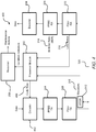
- FIG. 4 illustrates an embodiment of an exemplary architecture 400, where the system may utilize adaptive coding through encoder 402 and decoder 404 so as to improve the link quality and minimize the probability of error.
- Architecture 400 is substantially similar to architecture 300 shown and described in FIG. 3 ; however, architecture 400 utilizes a feedback loop through encoder 402 that assigns a parity bit on data transmitted through link 320 that can help to detect bit errors that were introduced in the link 320. If the link 320 is degraded, processor module 302 may compute a code rate 406 that can be utilized to improve the performance of fiber link 320.
- Code rate 406 is a coded signal that is composed of data and parity bits.
- the code rate 406 is a ratio of data bits to total bits, where total bits is the sum of data and parity bits.
- the probability of error can be reduced by increasing the quantity of parity bits. This reduces the data throughput of the link 320, while increasing the quality of the link 320.
- the system may adaptively alter the code rate 406 when link degradation is detected in order to ensure a high quality link 320.
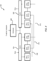
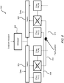
- FIGS. 5 and 6 illustrate an exemplary architecture 500, where a parallel fiber system is composed of multiple fiber links 508-512 for transmitting data through fiber network 206 ( FIG. 2 ).
- Each fiber link in the plurality of fiber links 508-512 is associated with a pair of fiber transceivers comprising a fiber transmitter and fiber receiver.
- Architecture 500 can be used to overcome network faults in one or more fiber links 508-512 through self-healing.
- fiber network 206 FIG. 2
- the architecture 500 utilizes a scheduler 502 in communication with processor module 302 ( FIGS. 3-4 ) and switches 505 and 506.
- scheduler 502 can select a particular fiber link to use for transmitting data. In cases where more data is available than what a fiber link can handle, the scheduler 502 schedules data transmission through other available fiber links 508-512 through time-division multiplexing (TDM).
- TDM time-division multiplexing
- processor module 302 may detect a degraded or faulty fiber link 510 through determination of link status 316 and BER 314 as discussed in FIGS 3-4 .
- Processor module 302 may autonomously notify scheduler 502 to remove fiber link 510 ( FIG. 6 ) from use, thus preventing data from being transmitted over a faulty link 510.
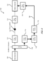
- FIGS. 7 and 8 illustrate an exemplary architecture 700 depicting a networked fiber system where multiple paths can be utilized to transfer data within fiber network 206 ( FIG. 2 ). Therefore, the system may utilize one path for normal operation, but be able to handle a failure by switching to an alternate data path as shown in FIG. 8 .
- Architecture 700 can be used to overcome network faults in a fiber network through self-healing. Under normal operation, data is transmitted from data generator 708 through fiber link 704 via fiber transmitter 710 and fiber receiver 712. A router 702 performs the function of routing data through one or more fiber links and transceivers from a data generator 708 to a data consumer 722 upon determination that a particular link is faulty such as, for example, fiber link 704 in FIG. 8 .
- processor module 302 may detect a degraded or faulty fiber link 704 ( FIG. 8 ) through determination of link status 316 and BER 314. Processor module 302 may provide this information to router 702, which can alter the flow of data from the faulty fiber link 704 to a healthy fiber link 706 via fiber transmitters 714 and 718 and fiber receivers 716 and 720. This ensures that any interruption in the data flow is limited and temporary.
Landscapes
- Physics & Mathematics (AREA)
- Electromagnetism (AREA)
- Engineering & Computer Science (AREA)
- Computer Networks & Wireless Communication (AREA)
- Signal Processing (AREA)
- Maintenance And Management Of Digital Transmission (AREA)
- Optical Communication System (AREA)
- Small-Scale Networks (AREA)
Description
- This invention was made with Government support with the United States Navy under Contract No. N68335-11-C-0192. The Government therefore has certain rights in this invention.
- The subject matter disclosed herein relates generally to the field of diagnosis and prognosis of networks and, more particularly, to a monitoring system for autonomously diagnosing and prognosticating adverse events or failures in a fiber network on machinery on aircraft.
- In comparison with copper networks, fiber optic networks in aircraft provide the benefits of smaller size, weight and power requirements, increased bandwidth, lower latency, and a smaller electromagnetic footprint; however, fault detection and mitigation in aircraft-deployed fiber networks are troublesome because a fault can be prevalent in-flight but not manifest on the ground. Condition-based Maintenance (CBM) has been used as the model for fault detection on fiber networks in these machines. CBM comprises a set of maintenance actions based on real-time or near real-time assessments of the condition of, e.g., avionics systems, that can be obtained from embedded sensors, and external tests and measurements, based on current condition indicators. But monitoring of fiber networks poses a challenge in bandwidth and computational resources for systems in aircraft and relies on the main computational resources of the aircraft.
- The monitoring of high-speed fiber networks may require significant sensor data volume and still not produce realistic fault coverage. Built-in Test (BIT) condition indicators (CIs) are incorporated into network equipment and transceivers for failure detection, but these typically do little to address the health of the entire network and subsystems. A method and architecture for autonomous CBM of fiber networks on aircraft and other machinery that addresses bandwidth and computational resources is desired.
-
US 5 767 956 A discloses an improved backward Brillouin scattering optical time domain reflectometry (OTDR) device which is capable of detecting the deterioration of or anticipating the fracture in an optical cable or optical fiber and measuring the position of the failure part with high resolution. -
US 2009/257743 A1 discloses a method and an apparatus for the measurement of the distribution of the reflectivity along an optical transmission line implemented by using the signal processing based on the cross-correlation function between the data signal with which the optical transmitter is modulated and the back-reflected signal returned to the optical transmitter to provide the in-service monitoring of the fiber-optic transmission link. -
EP 1 881 623 A2 -
US 2004/165888 A1 discloses an optical network connection test apparatus and method, wherein a test signal is introduced onto a light path of interest in the system, and the test signal is monitored downstream for signal integrity. Lack of signal integrity is used to identify a fault in the lightpath. Alternatively, optical loopbacks may be used to localize and identify a fault in the lightpath. The lightpath includes a source optical node connected to a sink optical node via intermediate optical nodes. -
US 2013/286852 A1 discloses a method of estimating a physical location of a network fault is provided. Information is received concerning the physical topology of the network by data pulls of information concerning network components and terminal network elements and geographic locations thereof. - The present invention relates to a method and a system for condition based maintenance of a fiber network in accordance with the appended claims.
- According to one aspect of the invention, a system for condition based maintenance of a fiber network includes a processor; and memory having instructions stored thereon that, when executed by the processor, cause the system to: transmit an optical signal over a plurality of fiber links in the fiber network; receive a response signal in response to the transmitting of the optical signal; and determine one or more condition indicators in response to the receiving of the response signal.
- In addition to one or more of the features described above, or as an alternative, further embodiments could include transmitting a pseudo-random bit sequence (PRBS) in the optical signal via an optical time domain reflectometer (OTDR).
- In addition to one or more of the features described above, or as an alternative, further embodiments could include transmitting parity bits in the PRBS.
- In addition to one or more of the features described above, or as an alternative, further embodiments could include determining a bit error ratio in the response signal.
- In addition to one or more of the features described above, or as an alternative, further embodiments could include determining a faulty fiber link of the plurality of fiber links in response to the determining of the bit error ratio.
- In addition to one or more of the features described above, or as an alternative, further embodiments could include routing the optical signal away from the faulty fiber link in response to the determining of the bit error ratio.
- In addition to one or more of the features described above, or as an alternative, further embodiments could include a response signal that comprises a reflected signal indicative of a discontinuity in the fiber network.
- In addition to one or more of the features described above, or as an alternative, further embodiments could include comparing the response signal with a stored fault pattern in response to the receiving of the response signal.
- In addition to one or more of the features described above, or as an alternative, further embodiments could include transmitting the one or more condition indicators to a reasoner engine for prioritizing and ranking the one or more condition indicators.
- In addition to one or more of the features described above, or as an alternative, further embodiments could include a condition indicator that is indicative of a faulty link in transmission over the fiber network.
- According to another aspect of the invention, a method of condition based maintenance of a fiber network includes transmitting, with a processor, an optical signal over a plurality of fiber links in the fiber network; receiving, with the processor, a response signal in response to the transmitting of the optical signal; and determining, with the processor, one or more condition indicators in response to the receiving of the response signal.
- In addition to one or more of the features described above, or as an alternative, further embodiments could include transmitting a pseudo-random bit sequence (PRBS) in the optical signal.
- In addition to one or more of the features described above, or as an alternative, further embodiments could include transmitting parity bits in the PRBS.
- In addition to one or more of the features described above, or as an alternative, further embodiments could include determining a bit error ratio in the response signal.
- In addition to one or more of the features described above, or as an alternative, further embodiments could include determining a faulty fiber link of the plurality of fiber links in response to the determining of the bit error ratio.
- In addition to one or more of the features described above, or as an alternative, further embodiments could include routing the optical signal away from the faulty fiber link in response to the determining of the bit error ratio.
- In addition to one or more of the features described above, or as an alternative, further embodiments could include a response signal that comprises a reflected signal indicative of a discontinuity in the fiber network.
- In addition to one or more of the features described above, or as an alternative, further embodiments could include a response signal that is indicative of a link loss in transmission over the fiber network.
- In addition to one or more of the features described above, or as an alternative, further embodiments could include comparing the response signal with a stored fault pattern in response to the receiving of the response signal.
- In addition to one or more of the features described above, or as an alternative, further embodiments could include transmitting the one or more condition indicators to a reasoner engine for prioritizing and ranking the condition indicator.
- Other aspects, features and techniques of the invention will become more apparent from the following description taken in conjunction with the drawings.
- The subject matter, which is regarded as the invention, is particularly pointed out and distinctly claimed in the claims at the conclusion of the specification. The foregoing and other features, and advantages of the invention are apparent from the following detailed description taken in conjunction with the accompanying drawings in which like elements are numbered alike in the several FIGURES:
-
FIG. 1 is a perspective view of an exemplary aircraft for use with embodiments of the invention; and -
FIG. 2 is a block diagram illustrating an exemplary architecture according to an embodiment of the invention; -
FIG. 3 is an architecture illustrating use of a bit sequence to test quality of a fiber link according to an embodiment of the invention; -
FIG. 4 is an architecture illustrating use of adaptive coding to test quality of a fiber link according to an embodiment of the invention; -
FIG. 5 is an architecture illustrating use of a parallel fiber system for data transfer according to an embodiment of the invention; -
FIG. 6 is an architecture illustrating use of fiber system ofFIG. 5 but shown with self-healing of a fiber system according to an embodiment of the invention; -
FIG. 7 is an architecture illustrating use of a parallel network for data transfer according to an embodiment of the invention; and -
FIG. 8 is an architecture illustrating use of network ofFIG. 7 but shown with self-healing of a fiber network according to an embodiment of the invention. - Referring now to the drawings,
FIG. 1 illustrates a general perspective view of an exemplary vehicle in the form of a rotorcraft orhelicopter 100 that uses an integratedfault monitoring system 120 for autonomous CBM of a fiber network based on a quality of fiber link according to an embodiment of the invention. Helicopter 100 includes anaircraft computer 118 in data communication with afault monitoring system 120 through acommunication link 122. Inembodiments communication link 122 may be hard-wired or be wireless. In embodiments, additional fault monitoring systems substantially similar tofault monitoring system 120 may be provided which also communicate fault information toaircraft computer 118 in order to provide CBM information from subsystems onhelicopter 100. - In an embodiment,
aircraft computer 118 includes a vehicle reasoner engine 209 (FIG. 2 ) that includes a system fault model to prioritize and rank fault data that is received from one or morefault monitoring systems 120, onboardhelicopter 100, as will be described below in reference toFIG. 2 . Although a particular configuration forhelicopter 100 is illustrated and described in the disclosed embodiments, other vehicles such as, for example, fixed wing aircraft, ground vehicles and sea-based vehicles, in addition to fixed, non-vehicular installations, will also benefit from embodiments of the invention. While the invention is being discussed with reference to rotary-wing aircraft, where the size, weight, and power advantages of fiber over other technologies are exemplary, the concepts and ideas expressed herein can also benefit and be equally applicable to sea- and ground-based vehicles and to fixed installations. As such, embodiments of the disclosed invention are not restricted to application in aircraft, but are applicable wherever reliable fiber networks are desired. -
FIG. 2 illustratesarchitecture 200 for an autonomous CBM of a fiber network of aircraft 100 (FIG. 1 ) according to an embodiment of the invention.Architecture 200 includes afault monitoring system 120, comprising aprocessor module 202 that is in data communication withprocessor module 204 overfiber network 206. Theprocessing modules processor module 202 is in data communication withprocessor module 204 overdata bus 218; but, in an embodiment,processor module 202 may communicate wirelessly withprocessor module 204. In embodiments,fault monitoring system 120 may communicate equipment status or condition indicators to an integrated vehicle health management unit (IVHMU) 208 in order to rank probability of faults that are received byprocessor modules IVHMU 208 includes avehicle reasoner engine 209 that can make inferences about the operation of the subsystems based on models including ranking the probability of faults that are passed on fromprocessor modules Vehicle reasoner engine 209 stores a count of faults detected byfault monitoring system 120 and prioritizes the faults for further action by maintenance crews.Vehicle reasoner engine 209 can compare the received data to a table to determine the quality of a fiber link and whether it exceeds an allowable threshold, ranks the condition indicators in terms of severity and provides information for maintenance actions. As such, theIVHMU 208 increases forecasting confidence of faults in aircraft 100 (FIG. 1 ) by drawing on knowledge from other subsystems that are connected througharchitecture 200. Thefault monitoring system 120 can perform autonomous testing of the degradation offiber network 206 throughprocessor modules IVHMU 208 orprocessors 220, onaircraft computer 118, as is traditionally done in conventional architectures. Thefiber network 206 may be coupled to subsystems such as avionics systems, weapons systems or the like and can include connectors at each end ofprocessor modules processor modules architecture 200. - Also shown in
FIG. 2 ,processor modules transceivers fiber network 206 with signals in order to determine discontinuities (such as breaks) or link loss and bit error rates in transmission betweenprocessor module 202 andprocessor module 204.Processor modules fiber network 206 independently of theIVHMU 208.Processor modules integrated OTDR transceivers fiber network 206 for interrogating thefiber network 206.Processor modules memory processors memories processors memories Processors processing modules -
Processor module 204 is substantially similar toprocessor module 202 and includes an integrated optical time domain reflectometer (OTDR)transceiver 215 for transmitting optical signals overfiber network 206 for detecting faults and link loss infiber network 206. In embodiments,processor module 202 can include algorithms for implementing autonomous CBM offiber network 206 in addition to algorithms onprocessor module 202.Processor module 204 includesmemory 216 which stores one or more fault detection algorithms as executable instructions that is executed byprocessor 214. Also,memory 216 can store fault patterns that can be matched to resulting scatter patterns received overfiber network 206 in order to correlate to condition indicators. In embodiments, the instructions may be stored or organized in any manner and at any level of abstraction, such as in connection with the execution of the fault detection algorithms.Processor 214 may be any type of processor (CPU), including a general purpose processor, a digital signal processor, a microcontroller, an application specific integrated circuit, a field programmable gate array or the like. Also, in embodiments,memory 216 may include random access memory (RAM), read only memory (ROM), or other electronic, optical, magnetic or any other computer readable medium onto which is stored the fault detection algorithms. -
Processor module 202 can implement a fault detection algorithm in order to determine discontinuities or breaks infiber network 206. In an embodiment, the fault detection algorithms onprocessor module 202 provide instructions for fault isolation and detection of faults overfiber network 206. The fault detection algorithm commandsOTDR transceiver 211 to transmit a very-short duration, high-power, laser pulse over one or more fiber cables that definefiber network 206 and, thereafter, observe the returned reflections from the pulse. By comparing the observed time domain reflections response to the time domain response that would be expected for a non-damaged or intact fiber cable, a discontinuity in a fiber cable can be detected. Additionally, the time delay between the emission of the laser pulse and the detection of its partial reflection back from the damaged portion of the cable can be used to determine how far such light traveled and, hence, localizes the fault in the fiber cable by determining the distance to the damaged portion.Architecture 200 provides location information of a fault in the fiber cable within thefiber network 206. This provides advantages over conventional methods of fault detection, where lack of detection of a fault at a specific fiber cable or at a specific location requires that an entire harness having multiple fiber cables be replaced. While the fault detection algorithm is described with reference toprocessor module 202, in embodiments, fault detection algorithm may be implemented onprocessor module 204 or any other processor module in lieu of or in addition to that implemented onprocessor module 202. -
Processor modules data bus 218 constitute a networked, distributed architecture. In an embodiment, other sensors, such as vibration sensors, thermocouples, barometers, or other types of sensors may be attached to the processing modules, while the processors are also applied to execute algorithms on the sensor data. Theprocessing module memories - In embodiments,
processor module 202 can implement a fault detection algorithm for determining link-loss betweenprocessor modules fiber network 206.Processor module 202 can commandOTDR transceiver 211 to transmit pulses (or bit blasts) overfiber network 206 and observe the received data atprocessor module 204.Processor module 202 can calculate link-loss as a CI. Also, data stored inprocessor module 202 may be provided to IVHMU 208 for pre- or post-flight diagnostics such as, for example, to correlate received signal power with other devices and to correlate with fiber end face inspection. During normal operations,processor module 202 may communicate withprocessor module 204 by transmitting data overfiber network 206. In a post-test mode, when no data is sensed on thefiber network 206,processor module 202 may be commanded to determine degradation offiber network 206 wherebyOTDR transceiver 211pulses fiber network 206 with pulses and observes the time-resulting scatter patterns inprocessor module 204. These scatter patterns can be matched to stored fault patterns stored inmemory 212 which correlate to CIs. Each CI is evidence of a fault attribute forfiber network 206. In embodiments,IVHMU 208 may store a count of faults detected byfault monitoring system 120 and prioritize the faults for further action by maintenance crews. -
FIG. 3 illustratesexemplary application architecture 300 depicting one path ofprocessor module 302 where data such as a pseudo-random bit sequence (PRBS) pattern may be utilized to test the quality of afiber link 320 in fiber network 206 (FIG. 2 ).Processor module 302 is substantially similar toprocessor modules architecture 300 can includefiber transmitter 308 andfiber receiver 310 in communication withOTDR transceiver 312 and a PRBS transceiver having aPRBS transmitter 304 andPRBS receiver 306 in order to interrogate fiber network 206 (FIG. 2 ). With this method, a PRBS can be generated byPRBS transmitter 304 and transmitted throughfiber transmitter 308 at one end offiber link 320. The PRBS sequence is received byPRBS receiver 306 throughfiber receiver 310 at another end offiber link 320. The receiving end offiber link 320 synchronizes to the PRBS pattern. Bit errors that are introduced by degradation infiber link 320 can be detected and quantified atPRBS receiver 306. The bit error ratio 314 (BER) may be computed as the number of bit errors divided by the total number of bits that have been received. TheBER 314 can be used to quantify the quality offiber link 320, as well as measure the severity of degradation infiber link 320. TheBER 314 can be fed toprocessor module 302 and utilized to generate condition indicators defining a condition indication offiber link 320.Vehicle reasoner engine 209 can store condition indicators for determination of further actions by maintenance crews based on the received condition indicators. In embodiments, the PRBS sequence can be transmitted and received at a same node (e.g., processor module 202) or alternatively, can be received at anotherprocessor module 204 that represents another node infiber network 206. - The BER or similar methods can be utilized at different points during operation of the system. The BER method may be employed at startup as part of a built-in test (BIT). The quality of a fiber link can be quantified prior to sending data over the link. Additionally, the BER method may be utilized at scheduled time intervals during operation. If the link is not currently in use, then the
BER 314 may be measured. Thefiber receiver 310 may provide a binary output indicating thelink status 316 of the optical link. Information forlink status 316 can be fed toprocessor module 302 and utilized to generate condition indicators. Theprocessor module 302 may process information from anOTDR waveform 318 received from anOTDR module 312,link status 316 andBER 314 in order to compute condition indicators on the link. This information can be fed to the system in order to reduce the impact of degradation or failures in the system. -
FIG. 4 illustrates an embodiment of anexemplary architecture 400, where the system may utilize adaptive coding throughencoder 402 anddecoder 404 so as to improve the link quality and minimize the probability of error.Architecture 400 is substantially similar toarchitecture 300 shown and described inFIG. 3 ; however,architecture 400 utilizes a feedback loop throughencoder 402 that assigns a parity bit on data transmitted throughlink 320 that can help to detect bit errors that were introduced in thelink 320. If thelink 320 is degraded,processor module 302 may compute acode rate 406 that can be utilized to improve the performance offiber link 320.Code rate 406 is a coded signal that is composed of data and parity bits. Thecode rate 406 is a ratio of data bits to total bits, where total bits is the sum of data and parity bits. The probability of error can be reduced by increasing the quantity of parity bits. This reduces the data throughput of thelink 320, while increasing the quality of thelink 320. The system may adaptively alter thecode rate 406 when link degradation is detected in order to ensure ahigh quality link 320. -
FIGS. 5 and6 illustrate anexemplary architecture 500, where a parallel fiber system is composed of multiple fiber links 508-512 for transmitting data through fiber network 206 (FIG. 2 ). Each fiber link in the plurality of fiber links 508-512 is associated with a pair of fiber transceivers comprising a fiber transmitter and fiber receiver.Architecture 500 can be used to overcome network faults in one or more fiber links 508-512 through self-healing. As illustrated, fiber network 206 (FIG. 2 ) includes fiber links 508-512, with data link 510 being used as an example of a faulty fiber link. Thearchitecture 500 utilizes ascheduler 502 in communication with processor module 302 (FIGS. 3-4 ) and switches 505 and 506. In an example,scheduler 502 can select a particular fiber link to use for transmitting data. In cases where more data is available than what a fiber link can handle, thescheduler 502 schedules data transmission through other available fiber links 508-512 through time-division multiplexing (TDM). Using the techniques discussed inFIGS. 3-4 ,processor module 302 may detect a degraded orfaulty fiber link 510 through determination oflink status 316 andBER 314 as discussed inFIGS 3-4 .Processor module 302 may autonomously notifyscheduler 502 to remove fiber link 510 (FIG. 6 ) from use, thus preventing data from being transmitted over afaulty link 510. -
FIGS. 7 and8 illustrate anexemplary architecture 700 depicting a networked fiber system where multiple paths can be utilized to transfer data within fiber network 206 (FIG. 2 ). Therefore, the system may utilize one path for normal operation, but be able to handle a failure by switching to an alternate data path as shown inFIG. 8 .Architecture 700 can be used to overcome network faults in a fiber network through self-healing. Under normal operation, data is transmitted fromdata generator 708 throughfiber link 704 viafiber transmitter 710 andfiber receiver 712. Arouter 702 performs the function of routing data through one or more fiber links and transceivers from adata generator 708 to adata consumer 722 upon determination that a particular link is faulty such as, for example,fiber link 704 inFIG. 8 . Using the techniques discussed inFIGS. 3-4 ,processor module 302 may detect a degraded or faulty fiber link 704 (FIG. 8 ) through determination oflink status 316 andBER 314.Processor module 302 may provide this information torouter 702, which can alter the flow of data from thefaulty fiber link 704 to ahealthy fiber link 706 viafiber transmitters fiber receivers - The terminology used herein is for the purpose of describing particular embodiments only and is not intended to be limiting of the invention. While the description of the present invention has been presented for purposes of illustration and description, it is not intended to be exhaustive or limited to the invention in the form disclosed. For instance, aspects of the invention are not limited to rotorcraft, and can be used in fiber networks in fixed structures and other mobile vehicles such as fixed wing vehicles, land vehicles and sea-based vehicles. Many modifications, variations, alterations, substitutions or equivalent arrangements not hereto described will be apparent to those of ordinary skill in the art without departing from the scope of the invention. Additionally, while the various embodiments of the invention have been described, it is to be understood that aspects of the invention may include only some of the described embodiments. Accordingly, the invention is not to be seen as limited by the foregoing description, but is only limited by the scope of the appended claims.
Claims (6)
- A method of condition based maintenance of a fiber network of an aircraft (100) having a fault monitoring system (120) and an aircraft computer (118) which is in communication with the fault monitoring system (120), comprising:transmitting, with a PRBS transmitter (304) coupled to a processor (302) of the fault monitoring system (120), a pseudo-random bit sequence (PRBS) over a plurality of fiber links in the fiber network;receiving, with the processor (302), a bit error ratio (BER) in response to the transmitting of the PRBS;determining, with the processor (302), one or more condition indicators in response to the receiving of the PRBS, wherein the condition indicators are indicative of a faulty link in transmission over the fiber network;transmitting, with the processor (302), the one or more condition indicators to a reasoner (209) of the aircraft computer (118); andprioritizing and ranking, with the reasoner (209), the one or more condition indicators for maintenance actions of the fiber network.
- The method of claim 1, wherein parity bits are included in the PRBS.
- The method of any preceding claim, wherein the BER is measured while the fiber links are not currently in use.
- A fault monitoring system (120) for condition based maintenance of a fiber network of an aircraft (100), said aircraft having an aircraft computer (118) which is in communication with the fault monitoring system (120), the fault monitoring system (120) comprising:a processor (302); andmemory (212, 216) having instructions stored thereon that, when executed by the processor (302), cause the processor (302) to:generate a pseudorandom bit sequence (PRBS);transmit the PRBS over a plurality of fiber links in the fiber network, wherein the PRBS is generated and transmitted by a PRBS transmitter (304) coupled to the processor (302);receive a bit error ratio (BER) in response to the transmitting of the PRBS from a PRBS receiver (306); andthe instructions further cause the processor (302) to determine one or more condition indicators in response to the receiving of the PRBS, wherein the condition indicators are indicative of a faulty link in transmission over the fiber network,the instructions further cause the processor (302) to transmit the one or more condition indicators to a reasoner (209) of the aircraft computer (118), the reasoner (209) prioritizing and ranking the one or more condition indicators for maintenance actions.
- The system of claim 4, wherein the processor (302) is configured to transmit parity bits in the PRBS.
- The system of claim 4 or 5, wherein the BER is measured while the fiber links are not currently in use.
Applications Claiming Priority (2)
| Application Number | Priority Date | Filing Date | Title |
|---|---|---|---|
| US201461990768P | 2014-05-09 | 2014-05-09 | |
| PCT/US2015/019188 WO2015183364A2 (en) | 2014-05-09 | 2015-03-06 | Method and apparatus for condition based maintenance of fiber networks on vehicles |
Publications (3)
| Publication Number | Publication Date |
|---|---|
| EP3140637A2 EP3140637A2 (en) | 2017-03-15 |
| EP3140637A4 EP3140637A4 (en) | 2017-12-06 |
| EP3140637B1 true EP3140637B1 (en) | 2019-12-18 |
Family
ID=54700023
Family Applications (1)
| Application Number | Title | Priority Date | Filing Date |
|---|---|---|---|
| EP15799044.1A Active EP3140637B1 (en) | 2014-05-09 | 2015-03-06 | Method and apparatus for condition based maintenance of fiber networks on vehicles |
Country Status (3)
| Country | Link |
|---|---|
| US (1) | US10305587B2 (en) |
| EP (1) | EP3140637B1 (en) |
| WO (1) | WO2015183364A2 (en) |
Cited By (1)
| Publication number | Priority date | Publication date | Assignee | Title |
|---|---|---|---|---|
| DE102024200981A1 (en) * | 2024-02-02 | 2025-08-07 | Volkswagen Aktiengesellschaft | Method for testing an optical transmission path in a sensor system based on an optical time domain reflectometry method, as well as sensor system and vehicle |
Families Citing this family (5)
| Publication number | Priority date | Publication date | Assignee | Title |
|---|---|---|---|---|
| CN106656320B (en) * | 2015-10-29 | 2019-04-12 | 阿里巴巴集团控股有限公司 | Fiber channel loss measurement system, method and device for optical quantum communication business |
| FR3052273B1 (en) * | 2016-06-02 | 2018-07-06 | Airbus | PREDICTION OF TROUBLES IN AN AIRCRAFT |
| US10337935B2 (en) * | 2016-12-12 | 2019-07-02 | Sikorsky Aircraft Corporation | Systems and methods for integrated, multi-functional, fault tolerant sensing and communication |
| CN116961742B (en) * | 2023-07-24 | 2024-04-16 | 无锡亚天光电科技有限公司 | Portable single light source inspection instrument |
| CN117353807B (en) * | 2023-12-04 | 2024-03-05 | 唐山市艾科特科技有限公司 | Optical cable remote monitoring system and method based on artificial intelligence |
Citations (3)
| Publication number | Priority date | Publication date | Assignee | Title |
|---|---|---|---|---|
| US5926263A (en) * | 1996-10-10 | 1999-07-20 | Tyco Submarine Systems Ltd. | Side-tone OTDR for in-service optical cable monitoring |
| WO2013134404A1 (en) * | 2012-03-06 | 2013-09-12 | Adtran, Inc. | Optical communication devices having optical time domain reflectometers |
| US20130286852A1 (en) * | 2012-04-27 | 2013-10-31 | General Instrument Corporation | Estimating Physical Locations of Network Faults |
Family Cites Families (18)
| Publication number | Priority date | Publication date | Assignee | Title |
|---|---|---|---|---|
| JP2570016B2 (en) * | 1991-08-29 | 1997-01-08 | 富士通株式会社 | Path switch switching method for optical transmission equipment |
| JP3354759B2 (en) * | 1995-07-24 | 2002-12-09 | 株式会社アドバンテスト | Back Brillouin scattered light OTDR device, measurement method therefor, and optical communication line system using this device |
| US7181138B1 (en) | 1998-12-14 | 2007-02-20 | Tellabs Operations, Inc. | Optical network connection test apparatus and methods |
| US7167443B1 (en) * | 1999-09-10 | 2007-01-23 | Alcatel | System and method for packet level restoration of IP traffic using overhead signaling in a fiber optic ring network |
| US7095493B2 (en) | 2003-11-24 | 2006-08-22 | The Boeing Company | Optical time domain reflectometer and method of using the same |
| US7341384B2 (en) | 2005-03-30 | 2008-03-11 | The Boeing Company | Fiber optic transceiver module having built-in test capability and associated method |
| US8255112B2 (en) | 2005-10-28 | 2012-08-28 | The Boeing Company | Remote aircraft maintenance in a networked environment |
| CN101110645B (en) | 2006-07-18 | 2013-01-02 | 株式会社藤仓 | Optical transmission line monitoring device, optical transmission line monitioring method and computer program |
| US7484899B2 (en) | 2006-11-01 | 2009-02-03 | The Boeing Company | Small-form-factor fiber optic transceiver module having built-in test capability and method |
| US8509613B2 (en) | 2008-04-14 | 2013-08-13 | Korea Advanced Institute Of Science And Technology | Monitoring of optical transmission systems based on cross-correlation operation |
| US8306421B1 (en) | 2008-05-05 | 2012-11-06 | Rockwell Collins, Inc. | Passive optical avionics network including optical repeater |
| US8116940B2 (en) | 2008-06-18 | 2012-02-14 | The Boeing Company | Systems and method for collecting data in a vehicle |
| DK2332276T3 (en) | 2008-09-04 | 2012-02-27 | Ericsson Telefon Ab L M | Passive optical networks |
| DE102009022365B3 (en) | 2009-05-22 | 2010-12-09 | Adva Ag Optical Networking | Method and device for 1 + 1 protection of an optical transmission path |
| US8285438B2 (en) | 2009-11-16 | 2012-10-09 | Honeywell International Inc. | Methods systems and apparatus for analyzing complex systems via prognostic reasoning |
| US8417113B1 (en) | 2010-05-07 | 2013-04-09 | The Boeing Company | Auxiliary network for fiber optic system health management |
| US9680567B2 (en) | 2011-03-03 | 2017-06-13 | Acacia Communications, Inc. | Fault localization and fiber security in optical transponders |
| US20130089204A1 (en) * | 2011-10-11 | 2013-04-11 | Nucrypt Llc | Quantum encrypted data transmission in optically-amplified wdm communications |
-
2015
- 2015-03-06 WO PCT/US2015/019188 patent/WO2015183364A2/en not_active Ceased
- 2015-03-06 EP EP15799044.1A patent/EP3140637B1/en active Active
- 2015-03-06 US US15/310,036 patent/US10305587B2/en active Active
Patent Citations (3)
| Publication number | Priority date | Publication date | Assignee | Title |
|---|---|---|---|---|
| US5926263A (en) * | 1996-10-10 | 1999-07-20 | Tyco Submarine Systems Ltd. | Side-tone OTDR for in-service optical cable monitoring |
| WO2013134404A1 (en) * | 2012-03-06 | 2013-09-12 | Adtran, Inc. | Optical communication devices having optical time domain reflectometers |
| US20130286852A1 (en) * | 2012-04-27 | 2013-10-31 | General Instrument Corporation | Estimating Physical Locations of Network Faults |
Cited By (1)
| Publication number | Priority date | Publication date | Assignee | Title |
|---|---|---|---|---|
| DE102024200981A1 (en) * | 2024-02-02 | 2025-08-07 | Volkswagen Aktiengesellschaft | Method for testing an optical transmission path in a sensor system based on an optical time domain reflectometry method, as well as sensor system and vehicle |
Also Published As
| Publication number | Publication date |
|---|---|
| US20170264362A1 (en) | 2017-09-14 |
| US10305587B2 (en) | 2019-05-28 |
| EP3140637A4 (en) | 2017-12-06 |
| WO2015183364A3 (en) | 2016-03-10 |
| EP3140637A2 (en) | 2017-03-15 |
| WO2015183364A2 (en) | 2015-12-03 |
Similar Documents
| Publication | Publication Date | Title |
|---|---|---|
| US10305587B2 (en) | Method and apparatus for condition based maintenance of fiber networks on vehicles | |
| EP3968000A1 (en) | Fiber optic link intermittent fault detection and localization | |
| EP2726836B1 (en) | Otdr trace analysis in pon systems | |
| CN102104421B (en) | Branched optical fiber failure detection method and device for optical network, and optical network | |
| KR102621601B1 (en) | Appartus and method monitoring insulator strings | |
| KR20120109325A (en) | Testing and monitoring an electrical system | |
| CN103427898B (en) | Method and system for determining branch fault point of passive optical network | |
| CA2435678C (en) | Processing of optical performance data in an optical wavelength division multiplexed communication system | |
| US6614968B1 (en) | Spare fiber monitoring arrangement | |
| US8417113B1 (en) | Auxiliary network for fiber optic system health management | |
| JP7686986B2 (en) | Optical receiver and method for determining optical reception level | |
| US7916073B2 (en) | Method and apparatus for improving integrity communication in a satellite navigation system | |
| EP3138239B1 (en) | Method and unit for handling deteriorating hardware | |
| KR20160001521A (en) | Apparatus and method for monitoring optical communication line | |
| JP7243518B2 (en) | Optical fiber sensor system and obstacle avoidance method | |
| WO2021249639A1 (en) | Fault location in an optical ring network | |
| CN112491465A (en) | Optical fiber line detection control method, device, device and readable storage medium | |
| KR100692669B1 (en) | Real time optical cable monitoring system | |
| KR101770121B1 (en) | System for monitoring wire network fault based on reflectometry and method therefor | |
| CN108692746A (en) | Sensor monitoring terminal, sensing and monitoring system and sensor monitoring method | |
| US11438804B2 (en) | Method and apparatus for operating a wireless communication network | |
| JPWO2023136091A5 (en) | ||
| JP2016092709A (en) | Antenna system abnormality detection method, system of distributed antenna, and repeating device using the same | |
| US20080144535A1 (en) | Ring-type network and fairness execution program for ring-type network | |
| US10819423B2 (en) | Network node, an optical transceiving unit and methods therein for determining information associated with an optical fiber |
Legal Events
| Date | Code | Title | Description |
|---|---|---|---|
| STAA | Information on the status of an ep patent application or granted ep patent |
Free format text: STATUS: THE INTERNATIONAL PUBLICATION HAS BEEN MADE |
|
| PUAI | Public reference made under article 153(3) epc to a published international application that has entered the european phase |
Free format text: ORIGINAL CODE: 0009012 |
|
| STAA | Information on the status of an ep patent application or granted ep patent |
Free format text: STATUS: REQUEST FOR EXAMINATION WAS MADE |
|
| 17P | Request for examination filed |
Effective date: 20161125 |
|
| AK | Designated contracting states |
Kind code of ref document: A2 Designated state(s): AL AT BE BG CH CY CZ DE DK EE ES FI FR GB GR HR HU IE IS IT LI LT LU LV MC MK MT NL NO PL PT RO RS SE SI SK SM TR |
|
| AX | Request for extension of the european patent |
Extension state: BA ME |
|
| DAV | Request for validation of the european patent (deleted) | ||
| DAX | Request for extension of the european patent (deleted) | ||
| A4 | Supplementary search report drawn up and despatched |
Effective date: 20171106 |
|
| RIC1 | Information provided on ipc code assigned before grant |
Ipc: G01N 21/84 20060101AFI20171027BHEP |
|
| STAA | Information on the status of an ep patent application or granted ep patent |
Free format text: STATUS: EXAMINATION IS IN PROGRESS |
|
| 17Q | First examination report despatched |
Effective date: 20180914 |
|
| REG | Reference to a national code |
Ref country code: DE Ref legal event code: R079 Ref document number: 602015043978 Country of ref document: DE Free format text: PREVIOUS MAIN CLASS: G01N0021840000 Ipc: H04B0010071000 |
|
| RIC1 | Information provided on ipc code assigned before grant |
Ipc: H04B 10/25 20130101ALI20190412BHEP Ipc: H04B 10/071 20130101AFI20190412BHEP Ipc: H04B 10/077 20130101ALI20190412BHEP Ipc: H04B 10/079 20130101ALI20190412BHEP |
|
| GRAP | Despatch of communication of intention to grant a patent |
Free format text: ORIGINAL CODE: EPIDOSNIGR1 |
|
| STAA | Information on the status of an ep patent application or granted ep patent |
Free format text: STATUS: GRANT OF PATENT IS INTENDED |
|
| INTG | Intention to grant announced |
Effective date: 20190621 |
|
| GRAS | Grant fee paid |
Free format text: ORIGINAL CODE: EPIDOSNIGR3 |
|
| GRAA | (expected) grant |
Free format text: ORIGINAL CODE: 0009210 |
|
| STAA | Information on the status of an ep patent application or granted ep patent |
Free format text: STATUS: THE PATENT HAS BEEN GRANTED |
|
| AK | Designated contracting states |
Kind code of ref document: B1 Designated state(s): AL AT BE BG CH CY CZ DE DK EE ES FI FR GB GR HR HU IE IS IT LI LT LU LV MC MK MT NL NO PL PT RO RS SE SI SK SM TR |
|
| REG | Reference to a national code |
Ref country code: CH Ref legal event code: EP |
|
| REG | Reference to a national code |
Ref country code: IE Ref legal event code: FG4D |
|
| REG | Reference to a national code |
Ref country code: DE Ref legal event code: R096 Ref document number: 602015043978 Country of ref document: DE |
|
| REG | Reference to a national code |
Ref country code: AT Ref legal event code: REF Ref document number: 1215718 Country of ref document: AT Kind code of ref document: T Effective date: 20200115 |
|
| REG | Reference to a national code |
Ref country code: NL Ref legal event code: MP Effective date: 20191218 |
|
| PG25 | Lapsed in a contracting state [announced via postgrant information from national office to epo] |
Ref country code: SE Free format text: LAPSE BECAUSE OF FAILURE TO SUBMIT A TRANSLATION OF THE DESCRIPTION OR TO PAY THE FEE WITHIN THE PRESCRIBED TIME-LIMIT Effective date: 20191218 Ref country code: LV Free format text: LAPSE BECAUSE OF FAILURE TO SUBMIT A TRANSLATION OF THE DESCRIPTION OR TO PAY THE FEE WITHIN THE PRESCRIBED TIME-LIMIT Effective date: 20191218 Ref country code: LT Free format text: LAPSE BECAUSE OF FAILURE TO SUBMIT A TRANSLATION OF THE DESCRIPTION OR TO PAY THE FEE WITHIN THE PRESCRIBED TIME-LIMIT Effective date: 20191218 Ref country code: BG Free format text: LAPSE BECAUSE OF FAILURE TO SUBMIT A TRANSLATION OF THE DESCRIPTION OR TO PAY THE FEE WITHIN THE PRESCRIBED TIME-LIMIT Effective date: 20200318 Ref country code: FI Free format text: LAPSE BECAUSE OF FAILURE TO SUBMIT A TRANSLATION OF THE DESCRIPTION OR TO PAY THE FEE WITHIN THE PRESCRIBED TIME-LIMIT Effective date: 20191218 Ref country code: GR Free format text: LAPSE BECAUSE OF FAILURE TO SUBMIT A TRANSLATION OF THE DESCRIPTION OR TO PAY THE FEE WITHIN THE PRESCRIBED TIME-LIMIT Effective date: 20200319 Ref country code: NO Free format text: LAPSE BECAUSE OF FAILURE TO SUBMIT A TRANSLATION OF THE DESCRIPTION OR TO PAY THE FEE WITHIN THE PRESCRIBED TIME-LIMIT Effective date: 20200318 |
|
| REG | Reference to a national code |
Ref country code: LT Ref legal event code: MG4D |
|
| PG25 | Lapsed in a contracting state [announced via postgrant information from national office to epo] |
Ref country code: HR Free format text: LAPSE BECAUSE OF FAILURE TO SUBMIT A TRANSLATION OF THE DESCRIPTION OR TO PAY THE FEE WITHIN THE PRESCRIBED TIME-LIMIT Effective date: 20191218 Ref country code: RS Free format text: LAPSE BECAUSE OF FAILURE TO SUBMIT A TRANSLATION OF THE DESCRIPTION OR TO PAY THE FEE WITHIN THE PRESCRIBED TIME-LIMIT Effective date: 20191218 |
|
| PG25 | Lapsed in a contracting state [announced via postgrant information from national office to epo] |
Ref country code: AL Free format text: LAPSE BECAUSE OF FAILURE TO SUBMIT A TRANSLATION OF THE DESCRIPTION OR TO PAY THE FEE WITHIN THE PRESCRIBED TIME-LIMIT Effective date: 20191218 |
|
| PG25 | Lapsed in a contracting state [announced via postgrant information from national office to epo] |
Ref country code: PT Free format text: LAPSE BECAUSE OF FAILURE TO SUBMIT A TRANSLATION OF THE DESCRIPTION OR TO PAY THE FEE WITHIN THE PRESCRIBED TIME-LIMIT Effective date: 20200513 Ref country code: CZ Free format text: LAPSE BECAUSE OF FAILURE TO SUBMIT A TRANSLATION OF THE DESCRIPTION OR TO PAY THE FEE WITHIN THE PRESCRIBED TIME-LIMIT Effective date: 20191218 Ref country code: RO Free format text: LAPSE BECAUSE OF FAILURE TO SUBMIT A TRANSLATION OF THE DESCRIPTION OR TO PAY THE FEE WITHIN THE PRESCRIBED TIME-LIMIT Effective date: 20191218 Ref country code: EE Free format text: LAPSE BECAUSE OF FAILURE TO SUBMIT A TRANSLATION OF THE DESCRIPTION OR TO PAY THE FEE WITHIN THE PRESCRIBED TIME-LIMIT Effective date: 20191218 Ref country code: NL Free format text: LAPSE BECAUSE OF FAILURE TO SUBMIT A TRANSLATION OF THE DESCRIPTION OR TO PAY THE FEE WITHIN THE PRESCRIBED TIME-LIMIT Effective date: 20191218 |
|
| PG25 | Lapsed in a contracting state [announced via postgrant information from national office to epo] |
Ref country code: IS Free format text: LAPSE BECAUSE OF FAILURE TO SUBMIT A TRANSLATION OF THE DESCRIPTION OR TO PAY THE FEE WITHIN THE PRESCRIBED TIME-LIMIT Effective date: 20200418 Ref country code: SK Free format text: LAPSE BECAUSE OF FAILURE TO SUBMIT A TRANSLATION OF THE DESCRIPTION OR TO PAY THE FEE WITHIN THE PRESCRIBED TIME-LIMIT Effective date: 20191218 Ref country code: SM Free format text: LAPSE BECAUSE OF FAILURE TO SUBMIT A TRANSLATION OF THE DESCRIPTION OR TO PAY THE FEE WITHIN THE PRESCRIBED TIME-LIMIT Effective date: 20191218 |
|
| REG | Reference to a national code |
Ref country code: DE Ref legal event code: R097 Ref document number: 602015043978 Country of ref document: DE |
|
| REG | Reference to a national code |
Ref country code: AT Ref legal event code: MK05 Ref document number: 1215718 Country of ref document: AT Kind code of ref document: T Effective date: 20191218 |
|
| PLBE | No opposition filed within time limit |
Free format text: ORIGINAL CODE: 0009261 |
|
| STAA | Information on the status of an ep patent application or granted ep patent |
Free format text: STATUS: NO OPPOSITION FILED WITHIN TIME LIMIT |
|
| PG25 | Lapsed in a contracting state [announced via postgrant information from national office to epo] |
Ref country code: DK Free format text: LAPSE BECAUSE OF FAILURE TO SUBMIT A TRANSLATION OF THE DESCRIPTION OR TO PAY THE FEE WITHIN THE PRESCRIBED TIME-LIMIT Effective date: 20191218 Ref country code: ES Free format text: LAPSE BECAUSE OF FAILURE TO SUBMIT A TRANSLATION OF THE DESCRIPTION OR TO PAY THE FEE WITHIN THE PRESCRIBED TIME-LIMIT Effective date: 20191218 Ref country code: MC Free format text: LAPSE BECAUSE OF FAILURE TO SUBMIT A TRANSLATION OF THE DESCRIPTION OR TO PAY THE FEE WITHIN THE PRESCRIBED TIME-LIMIT Effective date: 20191218 |
|
| REG | Reference to a national code |
Ref country code: CH Ref legal event code: PL |
|
| 26N | No opposition filed |
Effective date: 20200921 |
|
| PG25 | Lapsed in a contracting state [announced via postgrant information from national office to epo] |
Ref country code: AT Free format text: LAPSE BECAUSE OF FAILURE TO SUBMIT A TRANSLATION OF THE DESCRIPTION OR TO PAY THE FEE WITHIN THE PRESCRIBED TIME-LIMIT Effective date: 20191218 Ref country code: SI Free format text: LAPSE BECAUSE OF FAILURE TO SUBMIT A TRANSLATION OF THE DESCRIPTION OR TO PAY THE FEE WITHIN THE PRESCRIBED TIME-LIMIT Effective date: 20191218 |
|
| REG | Reference to a national code |
Ref country code: BE Ref legal event code: MM Effective date: 20200331 |
|
| PG25 | Lapsed in a contracting state [announced via postgrant information from national office to epo] |
Ref country code: LU Free format text: LAPSE BECAUSE OF NON-PAYMENT OF DUE FEES Effective date: 20200306 |
|
| PG25 | Lapsed in a contracting state [announced via postgrant information from national office to epo] |
Ref country code: IT Free format text: LAPSE BECAUSE OF FAILURE TO SUBMIT A TRANSLATION OF THE DESCRIPTION OR TO PAY THE FEE WITHIN THE PRESCRIBED TIME-LIMIT Effective date: 20191218 Ref country code: IE Free format text: LAPSE BECAUSE OF NON-PAYMENT OF DUE FEES Effective date: 20200306 Ref country code: LI Free format text: LAPSE BECAUSE OF NON-PAYMENT OF DUE FEES Effective date: 20200331 Ref country code: CH Free format text: LAPSE BECAUSE OF NON-PAYMENT OF DUE FEES Effective date: 20200331 |
|
| PG25 | Lapsed in a contracting state [announced via postgrant information from national office to epo] |
Ref country code: BE Free format text: LAPSE BECAUSE OF NON-PAYMENT OF DUE FEES Effective date: 20200331 Ref country code: PL Free format text: LAPSE BECAUSE OF FAILURE TO SUBMIT A TRANSLATION OF THE DESCRIPTION OR TO PAY THE FEE WITHIN THE PRESCRIBED TIME-LIMIT Effective date: 20191218 |
|
| PG25 | Lapsed in a contracting state [announced via postgrant information from national office to epo] |
Ref country code: TR Free format text: LAPSE BECAUSE OF FAILURE TO SUBMIT A TRANSLATION OF THE DESCRIPTION OR TO PAY THE FEE WITHIN THE PRESCRIBED TIME-LIMIT Effective date: 20191218 Ref country code: MT Free format text: LAPSE BECAUSE OF FAILURE TO SUBMIT A TRANSLATION OF THE DESCRIPTION OR TO PAY THE FEE WITHIN THE PRESCRIBED TIME-LIMIT Effective date: 20191218 Ref country code: CY Free format text: LAPSE BECAUSE OF FAILURE TO SUBMIT A TRANSLATION OF THE DESCRIPTION OR TO PAY THE FEE WITHIN THE PRESCRIBED TIME-LIMIT Effective date: 20191218 |
|
| PG25 | Lapsed in a contracting state [announced via postgrant information from national office to epo] |
Ref country code: MK Free format text: LAPSE BECAUSE OF FAILURE TO SUBMIT A TRANSLATION OF THE DESCRIPTION OR TO PAY THE FEE WITHIN THE PRESCRIBED TIME-LIMIT Effective date: 20191218 |
|
| PGFP | Annual fee paid to national office [announced via postgrant information from national office to epo] |
Ref country code: GB Payment date: 20260327 Year of fee payment: 12 |
|
| PGFP | Annual fee paid to national office [announced via postgrant information from national office to epo] |
Ref country code: DE Payment date: 20260327 Year of fee payment: 12 |
|
| PGFP | Annual fee paid to national office [announced via postgrant information from national office to epo] |
Ref country code: FR Payment date: 20260325 Year of fee payment: 12 |