EP3140100B1 - Machine and method for packaging infusion products - Google Patents
Machine and method for packaging infusion products Download PDFInfo
- Publication number
- EP3140100B1 EP3140100B1 EP15719969.6A EP15719969A EP3140100B1 EP 3140100 B1 EP3140100 B1 EP 3140100B1 EP 15719969 A EP15719969 A EP 15719969A EP 3140100 B1 EP3140100 B1 EP 3140100B1
- Authority
- EP
- European Patent Office
- Prior art keywords
- continuous
- articles
- continuous web
- band
- along
- Prior art date
- Legal status (The legal status is an assumption and is not a legal conclusion. Google has not performed a legal analysis and makes no representation as to the accuracy of the status listed.)
- Active
Links
Images


Classifications
-
- B—PERFORMING OPERATIONS; TRANSPORTING
- B65—CONVEYING; PACKING; STORING; HANDLING THIN OR FILAMENTARY MATERIAL
- B65B—MACHINES, APPARATUS OR DEVICES FOR, OR METHODS OF, PACKAGING ARTICLES OR MATERIALS; UNPACKING
- B65B9/00—Enclosing successive articles, or quantities of material, e.g. liquids or semiliquids, in flat, folded, or tubular webs of flexible sheet material; Subdividing filled flexible tubes to form packages
- B65B9/02—Enclosing successive articles, or quantities of material between opposed webs
-
- B—PERFORMING OPERATIONS; TRANSPORTING
- B65—CONVEYING; PACKING; STORING; HANDLING THIN OR FILAMENTARY MATERIAL
- B65B—MACHINES, APPARATUS OR DEVICES FOR, OR METHODS OF, PACKAGING ARTICLES OR MATERIALS; UNPACKING
- B65B29/00—Packaging of materials presenting special problems
- B65B29/02—Packaging of substances, e.g. tea, which are intended to be infused in the package
- B65B29/028—Packaging of substances, e.g. tea, which are intended to be infused in the package packaging infusion material into filter bags
-
- B—PERFORMING OPERATIONS; TRANSPORTING
- B65—CONVEYING; PACKING; STORING; HANDLING THIN OR FILAMENTARY MATERIAL
- B65B—MACHINES, APPARATUS OR DEVICES FOR, OR METHODS OF, PACKAGING ARTICLES OR MATERIALS; UNPACKING
- B65B35/00—Supplying, feeding, arranging or orientating articles to be packaged
- B65B35/30—Arranging and feeding articles in groups
- B65B35/40—Arranging and feeding articles in groups by reciprocating or oscillatory pushers
-
- B—PERFORMING OPERATIONS; TRANSPORTING
- B65—CONVEYING; PACKING; STORING; HANDLING THIN OR FILAMENTARY MATERIAL
- B65B—MACHINES, APPARATUS OR DEVICES FOR, OR METHODS OF, PACKAGING ARTICLES OR MATERIALS; UNPACKING
- B65B35/00—Supplying, feeding, arranging or orientating articles to be packaged
- B65B35/30—Arranging and feeding articles in groups
- B65B35/46—Arranging and feeding articles in groups by rotary conveyors
-
- B—PERFORMING OPERATIONS; TRANSPORTING
- B65—CONVEYING; PACKING; STORING; HANDLING THIN OR FILAMENTARY MATERIAL
- B65B—MACHINES, APPARATUS OR DEVICES FOR, OR METHODS OF, PACKAGING ARTICLES OR MATERIALS; UNPACKING
- B65B51/00—Devices for, or methods of, sealing or securing package folds or closures; Devices for gathering or twisting wrappers, or necks of bags
- B65B51/10—Applying or generating heat or pressure or combinations thereof
- B65B51/26—Devices specially adapted for producing transverse or longitudinal seams in webs or tubes
- B65B51/30—Devices, e.g. jaws, for applying pressure and heat, e.g. for subdividing filled tubes
- B65B51/306—Counter-rotating devices
-
- B—PERFORMING OPERATIONS; TRANSPORTING
- B65—CONVEYING; PACKING; STORING; HANDLING THIN OR FILAMENTARY MATERIAL
- B65B—MACHINES, APPARATUS OR DEVICES FOR, OR METHODS OF, PACKAGING ARTICLES OR MATERIALS; UNPACKING
- B65B61/00—Auxiliary devices, not otherwise provided for, for operating on sheets, blanks, webs, binding material, containers or packages
- B65B61/04—Auxiliary devices, not otherwise provided for, for operating on sheets, blanks, webs, binding material, containers or packages for severing webs, or for separating joined packages
- B65B61/06—Auxiliary devices, not otherwise provided for, for operating on sheets, blanks, webs, binding material, containers or packages for severing webs, or for separating joined packages by cutting
- B65B61/08—Auxiliary devices, not otherwise provided for, for operating on sheets, blanks, webs, binding material, containers or packages for severing webs, or for separating joined packages by cutting using rotary cutters
Definitions
- the present invention relates to a machine and method for the production of infusion products.
- the individual sealed envelopes are then generally ordered into pre-established groups and packaged in respective boxes or hard cardboard packages for sale.
- Packaging machines of bags or capsules comprising a feeding hopper of the envelopes to which a vertical tube of wrapping material is connected, in which groups of bags are inserted by gravity.
- the tube is obtained by welding the end edges of a continuous strip/web of wrapping material, thus defining a longitudinal fin-shaped junction.
- Welding means are positioned downstream of the hopper for forming a plurality of sealed containment envelopes of the bags, suitable for welding the vertical tube of wrapping material along respective transversal junctions forming a continuous succession of sealed envelopes.
- a cutting device positioned downstream of the welding means separates each sealed envelope from the envelope connected to it.
- a further drawback is the cost component of the wrapping material used for individually packaging the bags.
- This component in fact, is relatively high as the vertical tube of wrapping material used in the packaging machines of the known type has a much greater diameter with respect to the encumbrance of each single envelope or capsule.
- the longitudinal fin-shaped junction of the tube requires the use of a web of wrapping material having considerable transversal dimensions.
- packaging machines with a vertical tube of wrapping material are machines having a relatively limited hourly production due to the maximum production rates that can be reached.
- the advance path P has at least one section which develops along a horizontal lying plane along which closing means of the continuous web are positioned, around at least part of a respective group of articles.
- the section of path which develops according to a horizontal lying plane advantageously allows the production rate of the packaging machine to be increased with respect to the known art.
- the reference number 1 indicates a machine for the production of infusion products.
- the machine 1 comprises a device 2 for producing individual articles 3, each of which comprises a dose 4 of infusion material.
- Individual articles 3 preferably refers to bags or capsules of filter material containing infusion products such as, for example, tea, aromatic herbs, dried fruit, coffee, barley, etc.
- a continuous succession 5 of individual articles 3 is fed, at the outlet of the forming device 2, to respective cutting means 6 suitable for separating an individual article 3 from the subsequent article, as illustrated in figure 3 .
- the machine 1 comprises a packaging device 7 of groups 8 of individual articles 3 in a respective containment envelope 9.
- the machine 1 comprises formation means 10 of the groups 8 of articles 3.
- the formation means 10 of the groups 8 are positioned downstream of the cutting means 6 of the continuous succession 5 of individual articles 3.
- the formation means 10 comprise a withholding element 13 of the articles 3 positioned in correspondence with the formation station 12 of the groups 8.
- the withholding element 13 is suitable for withholding the individual articles 3 during the formation 12 of the groups 8.
- the withholding element 13 cooperates with the feeding device 11 for the formation of each group 8 of articles 3.
- the feeding device 11 of the individual articles 3 moves along a vertical direction, in particular downwards, and viceversa.
- An articulated system 14 moves the feeding device 11 during the formation of each group 8.
- the withholding element 13 is equipped with a rotational movement, in particular oscillating, around a respective rotation axis 13a.
- the rotation axis 13a is a vertical rotation axis.
- the withholding element 13 comprises a supporting surface 15 of the articles 3 and an arm 16, hinged to the rotation axis 13a, for moving the supporting surface 15.
- the withholding element 13 When in use, the withholding element 13 maintains a rest position in correspondence with the formation station 12 during the formation of the group 8.
- the withholding element 13 rotates around its rotation axis 13a for disengaging the group 8 formed.
- an abutment element 17 is engaged with at least part of the articles 3 of the group 8 for withdrawing the articles 3 from the withholding element 13, in particular from the supporting surface 15.
- the machine 1 comprises transfer means 18 of the group 8 of articles 3 to the packaging device 7.
- the transfer means 18 are positioned downstream of the formation station 12 of the groups 8.
- the formation means 10 of the groups 8 feed each group 8 to the transfer means 18, as illustrated in figure 4 .
- the feeding device 10 moves the group 8 forward towards the transfer means 18, once it has become engaged with the last article 3 of the group 8, whereas, contemporaneously, the withholding element 13 becomes disengaged with the remaining part of the groups 8 withheld during its formation.
- the transfer means 18 comprise a conveyor 19 rotating around its rotation axis 19a.
- the closing means 28 join the two continuous webs 27, i.e. the first and second continuous web 31, 32, around at least part of a respective group 8 of articles 3 so that the groups 8 of articles 3 are interposed with respect to each other.
- the closing means 28 join the two continuous webs 27, i.e. the first and second continuous web 31, 32, along two transversal joining bands 29 and two longitudinal joining bands 30, with respect to the advance direction of the continuous web 27, defining the closed envelope 9 containing a respective group 8 of articles 3.
- the closing means 28 comprise a first welding element 33 suitable for producing the longitudinal joining bands 30 and a second welding element 34 suitable for producing the transversal joining bands 29.
- the first welding element 33 forms the two longitudinal joining bands 30 arranged with opposing bands with respect to the centre line of the continuous bands 27.
- the first welding element 33 is preferably positioned upstream of the second welding element 34, with respect to the advance direction of the continuous webs 27.
- the first welding element 33 comprises two pairs of welding rolls 35 rotating around respective rotation axes 35a.
- Each pair of rolls 35 is arranged with opposing bands with respect to the centre line of the continuous webs 27.
- the pairs of rolls 35 advantageously move the continuous webs 27 and interposed groups 8 along the advance path P, in particular along the horizontal section T.
- the packaging device 7 comprises at least one cutting device 36 of the continuous webs 27 of wrapping material.
- the cutting device 36 and the second welding element 34 are produced in a single welding and cutting element.
- the cutting device 36 comprises at least one blade 37 cooperating with a respective anvil 38 along the portions of continuous web 27 positioned between one transversal joining band 29 and a consecutive transversal band 29.
- the blade 37 and anvil 38 are coordinated for forming continuous successions of envelopes 9 connected to each other.
- the anvil 38 comprises a first portion 39 suitable for forming a plurality of scored lines 41 between one transversal joining band 29 and the consecutive transversal band 29 and a second portion 40 adjacent to the first portion 39 suitable for severing the continuous web 27 between one transversal joining band 29 and the consecutive band 29 for separating one envelope 9 from the consecutive envelope.
- the blade 37 is coordinated with the anvil 38 to cooperate with the first portion 39, forming the scored lines 41, or to cooperate with the second portion 40, for severing the continuous web 27.
- the blade 37 and the anvil 38 are mutually phased so that the blade 37 abuts against the first portion 39 forming the scored lines 41 so as to keep the envelopes 9 connected to each other.
- the first portion 39 has an abutment surface provided with a plurality of cavities or grooves 42, which reproduce the scored lines 41 in negative.
- the second portion 40 has a continuous and flat abutment surface for allowing the blade 37 to completely shear the one or more continuous webs 27.
- the present invention of a method for producing infusion products comprises a phase for forming individual articles 3, each of which comprises a dose 4 of infusion material, a packaging phase of groups 8 of individual articles 3 in a respective containment envelope 9.
- the packaging phase comprises a feeding phase of at least one continuous web 27 of wrapped material destined for individually wrapping each group 8 of individual articles 3 along a common advance path P of the groups 8 of articles 3 and continuous web 27.
- the method advantageously comprises a closing phase of the continuous web 27 around at least part of a respective group 8 of articles 3 along at least a section T of the advance path P developing according to a horizontal lying plane.
- the continuous web 27 is joined at least along a transversal joining band 29 with respect to the advance direction of the continuous web 27.
- the continuous web 27 is joined at least along a longitudinal joining band 30 with respect to the advance direction of the continuous web 27.
- the method comprises: a phase for feeding two continuous webs 27, in particular a first and a second continuous web 31, 32 of wrapping material, destined for individually wrapping each group 8 of individual articles 3; a phase for positioning the groups 8 of articles 3 on the continuous web 27, in particular the first continuous web 31 of wrapping material, along the above-mentioned horizontal section T, forming a continuous succession of groups 8 of articles 3; a phase for joining the first and second continuous web 31, 32 around at least part of a respective group 8 of articles 3 so that the groups 8 of individual articles 3 are interposed between the first and second continuous web 31, 32; a phase for joining the first and second continuous web 31, 32 along two transversal joining bands 29 and along two longitudinal joining bands 30, with respect to the advance direction of the first and second continuous band 31, 32, defining the envelope 9; a phase for severing one or more of the continuous webs 27 of wrapping material along respective portions of continuous web 27 arranged between one transversal joining band 29 and the consecutive band 29 for forming continuous successions of envelopes 9.
- the phase for severing one or more of the continuous webs 27 comprises a phase for forming a plurality of scored lines 41 between one transversal joining band 29 and the consecutive band 29 or a phase for severing the one or more continuous webs between one transversal joining band 29 and the consecutive band 29.
Landscapes
- Engineering & Computer Science (AREA)
- Mechanical Engineering (AREA)
- Containers And Plastic Fillers For Packaging (AREA)
- Auxiliary Devices For And Details Of Packaging Control (AREA)
Description
- The present invention relates to a machine and method for the production of infusion products.
- In particular, infusion products refer to bags or capsules of filter material containing infusion products such as, for example, tea, aromatic herbs, dried fruit, coffee, barley, etc...
- In order to maintain the aroma of infusion products with time, the individual packaging of one or more bags or capsules in a respective sealed envelope, is known.
- The individual sealed envelopes are then generally ordered into pre-established groups and packaged in respective boxes or hard cardboard packages for sale.
- Packaging machines of bags or capsules are known, comprising a feeding hopper of the envelopes to which a vertical tube of wrapping material is connected, in which groups of bags are inserted by gravity.
- In particular, the tube is obtained by welding the end edges of a continuous strip/web of wrapping material, thus defining a longitudinal fin-shaped junction.
- Welding means are positioned downstream of the hopper for forming a plurality of sealed containment envelopes of the bags, suitable for welding the vertical tube of wrapping material along respective transversal junctions forming a continuous succession of sealed envelopes.
- A cutting device positioned downstream of the welding means separates each sealed envelope from the envelope connected to it.
- These machines, however, have various drawbacks.
- As the groups of bags are inserted inside the vertical tube by gravity, they are arranged randomly and disorderly inside the respective sealed envelope.
- A further drawback is the cost component of the wrapping material used for individually packaging the bags.
- This component, in fact, is relatively high as the vertical tube of wrapping material used in the packaging machines of the known type has a much greater diameter with respect to the encumbrance of each single envelope or capsule.
- Furthermore, the longitudinal fin-shaped junction of the tube requires the use of a web of wrapping material having considerable transversal dimensions.
- It has also been found that packaging machines with a vertical tube of wrapping material are machines having a relatively limited hourly production due to the maximum production rates that can be reached.
-
GB 2228912 - There is therefore the necessity of providing a machine and method for the production of infusion products which can limit the costs of the groups of bags of filter material or capsules packaged individually with respect to the known art.
- In this respect, an aspect of the present invention is to provide a machine for the production of infusion products which comprises a device for producing individual articles, each of which comprises a dose of infusion material, and a packaging device of groups of individual articles in a respective containment envelope. The packaging device comprises feeding means of at least one continuous web of wrapping material destined for individually wrapping each group of individual articles, and a common advance path P of the groups of articles and continuous web.
- In particular, the advance path P has at least one section which develops along a horizontal lying plane along which closing means of the continuous web are positioned, around at least part of a respective group of articles.
- The section of path which develops according to a horizontal lying plane advantageously allows the production rate of the packaging machine to be increased with respect to the known art.
- A further advantage lies in the fact that the horizontal section of the advance path P avoids the use of the vertical tube of wrapping material for packaging the groups of individual articles.
- Further characteristics and advantages of the present invention will appear evident from the following description which is indicative, and therefore non-limiting, of a preferred embodiment of a machine for the production of infusion products as illustrated in the enclosed drawings, in which:
-
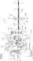
figure 1 illustrates a schematic front view of a machine for the production of infusion products according to the present invention; -
figure 2 illustrates a schematic plan view of the machine offigure 1 ; -
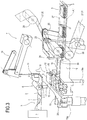
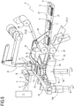
figures 3 to 6 illustrate a schematic perspective view of various functioning phases of the machine offigure 1 without some parts to illustrate others more clearly; -
Figure 7 illustrates a schematic perspective view in an enlarged scale of a detail of the machine offigure 1 . - The reference number 1 indicates a machine for the production of infusion products.
- The machine 1 comprises a
device 2 for producingindividual articles 3, each of which comprises adose 4 of infusion material. -
Individual articles 3 preferably refers to bags or capsules of filter material containing infusion products such as, for example, tea, aromatic herbs, dried fruit, coffee, barley, etc... - A
continuous succession 5 ofindividual articles 3 is fed, at the outlet of the formingdevice 2, to respective cutting means 6 suitable for separating anindividual article 3 from the subsequent article, as illustrated infigure 3 . - The machine 1 comprises a
packaging device 7 ofgroups 8 ofindividual articles 3 in arespective containment envelope 9. - The machine 1 comprises formation means 10 of the
groups 8 ofarticles 3. - The formation means 10 of the
groups 8 are positioned downstream of the cutting means 6 of thecontinuous succession 5 ofindividual articles 3. - The formation means 10 comprise a
feeding device 11 of theindividual articles 3 suitable for conveying at least oneindividual article 3 to aformation station 12 of thegroups 8. - The formation means 10 comprise a
withholding element 13 of thearticles 3 positioned in correspondence with theformation station 12 of thegroups 8. - The
withholding element 13 is suitable for withholding theindividual articles 3 during theformation 12 of thegroups 8. - The
withholding element 13 cooperates with thefeeding device 11 for the formation of eachgroup 8 ofarticles 3. - In the preferred embodiment, the
feeding device 11 of theindividual articles 3 moves along a vertical direction, in particular downwards, and viceversa. - An articulated
system 14 moves thefeeding device 11 during the formation of eachgroup 8. - The
withholding element 13 is equipped with a rotational movement, in particular oscillating, around arespective rotation axis 13a. - The
rotation axis 13a is a vertical rotation axis. - The
withholding element 13 comprises a supportingsurface 15 of thearticles 3 and anarm 16, hinged to therotation axis 13a, for moving the supportingsurface 15. - When in use, the
withholding element 13 maintains a rest position in correspondence with theformation station 12 during the formation of thegroup 8. - When the formation of the
group 8 is complete, thewithholding element 13 rotates around itsrotation axis 13a for disengaging thegroup 8 formed. - During the movement of the
withholding element 13, anabutment element 17 is engaged with at least part of thearticles 3 of thegroup 8 for withdrawing thearticles 3 from thewithholding element 13, in particular from the supportingsurface 15. - The machine 1 comprises transfer means 18 of the
group 8 ofarticles 3 to thepackaging device 7. - The transfer means 18 are positioned downstream of the
formation station 12 of thegroups 8. - In particular, the formation means 10 of the
groups 8 feed eachgroup 8 to the transfer means 18, as illustrated infigure 4 . - In particular, the
feeding device 10 moves thegroup 8 forward towards the transfer means 18, once it has become engaged with thelast article 3 of thegroup 8, whereas, contemporaneously, thewithholding element 13 becomes disengaged with the remaining part of thegroups 8 withheld during its formation. - The transfer means 18 comprise a
conveyor 19 rotating around itsrotation axis 19a. - The
rotation axis 19a of the conveyor is a vertical rotation axis. - The rotation axes of the
withholding element 13 and theconveyor 19 are parallel to each other. - The
conveyor 19 has a plurality ofhousing pockets 20 of arespective group 8 ofarticles 3. - The
pockets 20 are preferably angularly equidistant with respect to each other. - The transfer means 18 can be moved from a
collection station 21 to a releasingstation 22 of thegroups 8. - The
conveyor 19 transfers the groups of thecollection station 21 to the releasingstation 22 rotating around itsown axis 19a, in particular effecting a rotation of 90°, as illustrated infigure 5 . - The machine 1 comprises feeding means 23 of the
groups 8 ofarticles 3 to thepackaging device 7. - The feeding means 23 remove the
groups 8 from the transfer means 18 and release saidgroups 8 at thepackaging device 7. - The feeding means 23 translate the
groups 8 according to a horizontal advance direction. - The feeding means 23 comprise a
pusher 24 that causes arespective group 8 ofarticles 3 to advance. - The
pusher 24 is engaged with arespective group 8 ofarticles 3 housed in thepocket 20 of theconveyor 19 and moves thegroup 8 ofarticles 3 forward towards thepackaging device 7, as illustrated infigure 6 . - The feeding means 23 comprise an articulated
movement system 25 of thepusher 24. - The
packaging device 7 comprises feeding means 26 of at least acontinuous web 27 of wrapping material destined for individually wrapping eachgroup 8 ofindividual articles 3, and a common advance path P of thegroups 8 ofarticles 3 andcontinuous web 27. - According to the present invention, the advance path P has at least one section T which develops along a horizontal lying plane along which closing means 28 of the
continuous web 27 are positioned, around at least part of arespective group 8 ofarticles 3. - The closing means 28 join the
continuous web 27 at least along a joiningband 29 transversal with respect to the advance direction of thecontinuous web 27. - In other words, the joining
band 29 is transversal to the horizontal lying plane of the section T. - The closing means 28 join the
continuous web 27 at least along a joiningband 30 longitudinal with respect to the advance direction of thecontinuous web 27. - In other words, the longitudinal joining
band 30 is parallel to the horizontal lying plane of the section T. - In the preferred embodiment, the
packaging device 7 comprising feeding means 26 of twocontinuous webs 27, in particular a first and a second continuous web 31, 32 of wrapping material, destined for individually wrapping eachgroup 8 ofindividual articles 3. - The feeding means 23 of the
groups 8 ofarticles 3 position thegroups 8 on thecontinuous web 27, in particular the first continuous web 31 of wrapping material along the above-mentioned horizontal section T, forming a continuous succession ofgroups 8 ofarticles 3. - The closing means 28 join the two
continuous webs 27, i.e. the first and second continuous web 31, 32, around at least part of arespective group 8 ofarticles 3 so that thegroups 8 ofarticles 3 are interposed with respect to each other. - With reference to each
group 8, the closing means 28 join the twocontinuous webs 27, i.e. the first and second continuous web 31, 32, along two transversal joiningbands 29 and two longitudinal joiningbands 30, with respect to the advance direction of thecontinuous web 27, defining theclosed envelope 9 containing arespective group 8 ofarticles 3. - According to a preferred embodiment, the closing means 28 comprise a first welding element 33 suitable for producing the longitudinal joining
bands 30 and asecond welding element 34 suitable for producing the transversal joiningbands 29. - The first welding element 33 forms the two longitudinal joining
bands 30 arranged with opposing bands with respect to the centre line of thecontinuous bands 27. - The first welding element 33 is preferably positioned upstream of the
second welding element 34, with respect to the advance direction of thecontinuous webs 27. - The first welding element 33 comprises two pairs of welding rolls 35 rotating around
respective rotation axes 35a. - Each pair of
rolls 35 is arranged with opposing bands with respect to the centre line of thecontinuous webs 27. - The pairs of
rolls 35 advantageously move thecontinuous webs 27 and interposedgroups 8 along the advance path P, in particular along the horizontal section T. - The
packaging device 7 comprises at least onecutting device 36 of thecontinuous webs 27 of wrapping material. - The cutting
device 36 is preferably positioned along the horizontal section T of the advance path P. - In this embodiment, the cutting
device 36 and thesecond welding element 34 are produced in a single welding and cutting element. - The cutting
device 36 comprises at least oneblade 37 cooperating with arespective anvil 38 along the portions ofcontinuous web 27 positioned between one transversal joiningband 29 and a consecutivetransversal band 29. - The
blade 37 andanvil 38 are coordinated for forming continuous successions ofenvelopes 9 connected to each other. - In particular, the
anvil 38 comprises afirst portion 39 suitable for forming a plurality of scoredlines 41 between one transversal joiningband 29 and the consecutivetransversal band 29 and asecond portion 40 adjacent to thefirst portion 39 suitable for severing thecontinuous web 27 between one transversal joiningband 29 and theconsecutive band 29 for separating oneenvelope 9 from the consecutive envelope. - The
blade 37 is coordinated with theanvil 38 to cooperate with thefirst portion 39, forming the scoredlines 41, or to cooperate with thesecond portion 40, for severing thecontinuous web 27. - The
blade 37 and theanvil 38 rotate aroundrespective rotation axes - The
blade 37 and theanvil 38 are mutually phased so that theblade 37 abuts against thefirst portion 39 forming the scoredlines 41 so as to keep theenvelopes 9 connected to each other. - In order to produce
continuous successions 42 ofenvelopes 9, theblade 37 and theanvil 38 are mutually phased so that theblade 37 abuts against thesecond portion 40 to separate the first andlast envelope 9 of the respectivecontinuous succession 42. - As illustrated in
figure 7 , thefirst portion 39 has an abutment surface provided with a plurality of cavities orgrooves 42, which reproduce the scoredlines 41 in negative. - The
second portion 40 has a continuous and flat abutment surface for allowing theblade 37 to completely shear the one or morecontinuous webs 27. - The present invention of a method for producing infusion products comprises a phase for forming
individual articles 3, each of which comprises adose 4 of infusion material, a packaging phase ofgroups 8 ofindividual articles 3 in arespective containment envelope 9. - The packaging phase comprises a feeding phase of at least one
continuous web 27 of wrapped material destined for individually wrapping eachgroup 8 ofindividual articles 3 along a common advance path P of thegroups 8 ofarticles 3 andcontinuous web 27. - The method advantageously comprises a closing phase of the
continuous web 27 around at least part of arespective group 8 ofarticles 3 along at least a section T of the advance path P developing according to a horizontal lying plane. - During the closing phase, the
continuous web 27 is joined at least along a transversal joiningband 29 with respect to the advance direction of thecontinuous web 27. - During the closing phase, the
continuous web 27 is joined at least along a longitudinal joiningband 30 with respect to the advance direction of thecontinuous web 27. - The method comprises: a phase for feeding two
continuous webs 27, in particular a first and a second continuous web 31, 32 of wrapping material, destined for individually wrapping eachgroup 8 ofindividual articles 3;
a phase for positioning thegroups 8 ofarticles 3 on thecontinuous web 27, in particular the first continuous web 31 of wrapping material, along the above-mentioned horizontal section T, forming a continuous succession ofgroups 8 ofarticles 3;
a phase for joining the first and second continuous web 31, 32 around at least part of arespective group 8 ofarticles 3 so that thegroups 8 ofindividual articles 3 are interposed between the first and second continuous web 31, 32;
a phase for joining the first and second continuous web 31, 32 along two transversal joiningbands 29 and along two longitudinal joiningbands 30, with respect to the advance direction of the first and second continuous band 31, 32, defining theenvelope 9;
a phase for severing one or more of thecontinuous webs 27 of wrapping material along respective portions ofcontinuous web 27 arranged between one transversal joiningband 29 and theconsecutive band 29 for forming continuous successions ofenvelopes 9. - The phase for severing one or more of the
continuous webs 27 comprises a phase for forming a plurality of scoredlines 41 between one transversal joiningband 29 and theconsecutive band 29 or a phase for severing the one or more continuous webs between one transversal joiningband 29 and theconsecutive band 29. - The present invention allows the production rate of the packaging machine 1 to be increased, considerably reducing the costs for the packaging material into
envelopes 9 by the use of closing means 28 positioned along a horizontal section T of the advance path P of thecontinuous web 27.
Claims (14)
- A machine for making products for infusion comprising a device (2) for making individual articles (3), each comprising a dose (4) of material for infusion, and a device (7) for packaging groups (8) of individual articles (3) in a respective containment envelope (9); the packaging device (7) comprising feed means (26) for feeding at least one continuous web (27) of wrapping material intended to individually surround in an envelope each group (8) of individual articles (3), and a feed path (P) shared by the groups (8) of articles (3) and the continuous web (27);
where in the device the feed path (P) comprises at least one stretch (T) extending according to a horizontal lying plane along which closing means (28) are positioned for closing the continuous web (27) around at least part of a respective group (8) of articles (3), in which the packaging device (7) comprises at least one cutting unit (36) for cutting the one or more continuous webs (27) of wrapping material; characterized in that the cutting unit (36) comprising at least one blade (37) operating in conjunction with a respective anvil (38) along respective portions of the continuous web (27) positioned between one transversal joining band (29) and the consecutive band (29); the blade (37) and the anvil (38) being coordinated to produce continuous series of envelopes (9), in which the anvil (38) comprises a first portion (39) designed to make a plurality of scored lines (41) between one transversal joining band (29) and the consecutive band (29), and a second portion (40) adjacent to the first portion (39) designed to cut the one or more continuous webs (27) between one transversal joining band (29) and the consecutive band (29); the blade (37) being coordinated with the anvil (38) to make the scored lines (41) or to sever the one or more continuous webs (27), being the blade (37) and the anvil (38) are mutually phased so that the blade (37) abuts against the first portion (39) forming the scored lines (41) so as to keep the envelopes (9) connected to each other and being the blade (37) and the anvil (38) mutually phased so that the blade (37) abuts against the second portion (40) to separate the first and last envelope (9) of the respective continuous succession (42). - The machine according to claim 1, characterized in that the closing means (28) join the continuous web (27) at least along a joining band (29) which is transversal relative to the line of feed of the continuous web (27).
- The machine according to claim 1 or 2, characterized in that the closing means (28) join the continuous web (27) at least along a joining band (30) which is longitudinal relative to the line of feed of the continuous web (27).
- The machine according to any one of claims 1 to 3, characterized in that it comprises feed means (26) for feeding two continuous webs (27), in particular a first and a second continuous web (31, 32) of wrapping material, intended to individually surround in an envelope each group (8) of individual articles (3).
- The machine according to any one of claims 1 to 4, characterized in that it comprises feed means (23) for feeding the groups (8) of articles (3) to the packaging device (7); the feed means (23) positioning the groups (8) of articles (3) on the continuous web (27) of wrapping material along the horizontal stretch (T), creating a continuous series of groups (8) of articles (3).
- The machine according to any one of claims 1 to 5, characterized in that the closing means (28) join the one or more continuous webs (27) around at least part of a respective group (8) of articles (3) in such a way that the groups (8) of individual articles (3) are interposed between portions of the same continuous web (27) or between two different continuous webs (27), in particular a first and a second continuous web (31, 32) of wrapping material.
- The machine according to any one of claims 1 to 6, characterized in that, with reference to each group (8), the closing means (28) join the one or more continuous webs (27) along two joining bands (29) which are transversal and two joining bands (30) which are longitudinal relative to the line of feed of the continuous web (27), forming the closed envelope (9) containing a respective group (8) of articles (3).
- A method for making products for infusion comprising a step of making individual articles (3), each of which comprises a dose (4) of material for infusion, a step of packaging groups (8) of individual articles (3) in a respective containment envelope (9);
the packaging step comprising a step of feeding at least one continuous web (27) of wrapping material intended to individually surround in an envelope each group (8) of individual articles (3) along a feed path (P) shared by the groups (8) of articles (3) of the continuous web (27);
the method moreover comprises a step of closing the continuous web (27) around at least part of a respective group (8) of articles (3) along at least one stretch (T) of the feed path (P) extending according to a horizontal lying plane, a step of cutting at least one or more continuous webs (27) of wrapping material along respective portions of the continuous web (27) positioned between one transversal joining band (29) and the consecutive band (29) to produce continuous series of envelopes (9) in which the step of cutting the one or more continuous webs (27) comprises a step of making a plurality of scored lines (41) between one transversal joining band (29) and the consecutive band (29), or a step of severing the one or more continuous webs (27) between one transversal joining band (29) and the consecutive band (29) characterized in that the step of cutting is make with a cutting unit (36) comprising at least one blade (37) operating in conjunction with a respective anvil (38) along respective portions of the continuous web (27), being, in said step of cutting, the blade (37) and the anvil (38) coordinated to produce continuous series of envelopes (9), the anvil (38), in said step of cutting, comprising a first portion (39) designed to make a plurality of scored lines (41) between one transversal joining band (29) and the consecutive band (29), and a second portion (40) adjacent to the first portion (39) designed to cut the one or more continuous webs (27) between one transversal joining band (29) and the consecutive band (29); the blade (37) being coordinated with the anvil (38) to make the scored lines (41) or to sever the one or more continuous webs (27), being the blade (37) and the anvil (38) are mutually phased so that the blade (37) abuts against the first portion (39) forming the scored lines (41) so as to keep the envelopes (9) connected to each other and being the blade (37) and the anvil (38) mutually phased so that the blade (37) abuts against the second portion (40) to separate the first and last envelope (9) of the respective continuous succession (42). - The method according to claim 8, characterized in that during the closing step, the at least one or more continuous webs (27) is joined at least along a joining band (29) which is transversal relative to the line of feed of the continuous web (27).
- The method according to claim 9, characterised in that during the closing step the one or more continuous webs (27) is joined at least along a joining band (30) which is longitudinal relative to the line of feed of the continuous web (27).
- The method according to claim 8, characterised in that it comprises a step of feeding two continuous webs (27), in particular a first and a second continuous web (31, 32) of wrapping material, which are intended to individually surround in an envelope each group (8) of individual articles (3).
- The method according to any one of claims 8 to 11, characterised in that it comprises a step of positioning the groups (8) of articles (3) on the continuous web (27) of wrapping material along the horizontal stretch (T), producing a continuous series of groups (8) of articles (8).
- The method according to any one of claims 8 to 12, characterised in that it comprises a step of joining the at least one or more continuous webs (27) around at least part of a respective group (8) of articles (3) in such a way that the groups (8) of individual articles (3) are interposed between portions of the same continuous web (27) or between two different continuous webs (27), in particular a first and a second continuous web (31, 32) of wrapping material.
- The method according to any one of claims 8 to 13, characterised in that it comprises a step of joining the at least one or more continuous webs (27) along two joining bands (29) which are transversal and along two joining bands (30) which are longitudinal relative to the line of feed of the continuous web (27), forming the closed envelope (9) containing a respective group (8) of articles (3).
Priority Applications (1)
| Application Number | Priority Date | Filing Date | Title |
|---|---|---|---|
| PL15719969T PL3140100T3 (en) | 2014-05-08 | 2015-04-29 | Machine and method for packaging infusion products |
Applications Claiming Priority (2)
| Application Number | Priority Date | Filing Date | Title |
|---|---|---|---|
| ITBO20140274 | 2014-05-08 | ||
| PCT/EP2015/000910 WO2015169434A1 (en) | 2014-05-08 | 2015-04-29 | Machine and method for packaging infusion products |
Publications (2)
| Publication Number | Publication Date |
|---|---|
| EP3140100A1 EP3140100A1 (en) | 2017-03-15 |
| EP3140100B1 true EP3140100B1 (en) | 2018-01-24 |
Family
ID=51494338
Family Applications (1)
| Application Number | Title | Priority Date | Filing Date |
|---|---|---|---|
| EP15719969.6A Active EP3140100B1 (en) | 2014-05-08 | 2015-04-29 | Machine and method for packaging infusion products |
Country Status (3)
| Country | Link |
|---|---|
| EP (1) | EP3140100B1 (en) |
| PL (1) | PL3140100T3 (en) |
| WO (1) | WO2015169434A1 (en) |
Cited By (1)
| Publication number | Priority date | Publication date | Assignee | Title |
|---|---|---|---|---|
| EP4046923A1 (en) | 2021-02-18 | 2022-08-24 | Teepack Spezialmaschinen GmbH & Co. KG | Device for manufacturing bags filled with infusible material |
Families Citing this family (1)
| Publication number | Priority date | Publication date | Assignee | Title |
|---|---|---|---|---|
| IT201700002424A1 (en) * | 2017-01-11 | 2018-07-11 | Easysnap Tech S R L | ENGRAVING UNIT FOR REALIZING A SINGLE DOSE PACKAGE WITH BREAKING OPENING |
Family Cites Families (5)
| Publication number | Priority date | Publication date | Assignee | Title |
|---|---|---|---|---|
| US3943686A (en) * | 1974-09-05 | 1976-03-16 | Fmc Corporation | Wrapping machine with severing blade in crimping head |
| GB8905363D0 (en) * | 1989-03-09 | 1989-04-19 | Premier Brands Uk | Improvements relating to the packaging and marketing of tea bags |
| GB9112920D0 (en) * | 1991-06-14 | 1991-08-07 | Premier Brands Uk | Improvements relating to infusion packages |
| IT1299941B1 (en) * | 1998-03-27 | 2000-04-04 | Tecnomeccanica Srl | EQUIPMENT FOR THE FORMING OF A WELDABLE PAPER WRAP FOR THE PACKAGING OF A PRODUCT. |
| US6318894B1 (en) * | 1999-10-06 | 2001-11-20 | Kraft Foods Holdings, Inc. | Resealable flexible packages having hook design tear line |
-
2015
- 2015-04-29 EP EP15719969.6A patent/EP3140100B1/en active Active
- 2015-04-29 WO PCT/EP2015/000910 patent/WO2015169434A1/en not_active Ceased
- 2015-04-29 PL PL15719969T patent/PL3140100T3/en unknown
Cited By (2)
| Publication number | Priority date | Publication date | Assignee | Title |
|---|---|---|---|---|
| EP4046923A1 (en) | 2021-02-18 | 2022-08-24 | Teepack Spezialmaschinen GmbH & Co. KG | Device for manufacturing bags filled with infusible material |
| US11801955B2 (en) | 2021-02-18 | 2023-10-31 | Teepack Spezialmaschinen Gmbh & Co. Kg | Device for the production of bags filled with infusible material |
Also Published As
| Publication number | Publication date |
|---|---|
| EP3140100A1 (en) | 2017-03-15 |
| WO2015169434A1 (en) | 2015-11-12 |
| PL3140100T3 (en) | 2018-05-30 |
Similar Documents
| Publication | Publication Date | Title |
|---|---|---|
| EP2483163B1 (en) | Method and machine for packing infusion products into capsules | |
| US9527663B2 (en) | Machine for making filter bags for infusion products | |
| EP2483160B1 (en) | Machine for packing infusion products into capsules and featuring sealing unit | |
| CN104703883B (en) | Machine and method for packaging capsules in multi-capsule packaging | |
| EP2681119B1 (en) | Machine for producing filter bags with products for infusion and with an outer wrapper envelope | |
| US10793347B2 (en) | Machine for forming filter bags for infusion products | |
| EP3325348B1 (en) | Apparatus for making a food product for making a drink by infusion in a respective liquid | |
| CN103189025B (en) | For the method for packaging product and the packaging facilities for implementing the method | |
| EP3186153B1 (en) | Apparatus for producing packages of infusion products | |
| WO2011039707A1 (en) | Machine for packing infusion products into capsules | |
| EP3140100B1 (en) | Machine and method for packaging infusion products | |
| EP3126119B1 (en) | Tight seal system for the packaging of products | |
| EP4037977B1 (en) | Packaging machine for making filter bags with infusion products | |
| US20080047232A1 (en) | Infeed assembly for a continuous motion wrapping assembly | |
| CN110914162B (en) | Method and device for applying packaging aids | |
| EP3426561B1 (en) | Machine for making filter bags with infusion products | |
| EP3393914B1 (en) | Machine for forming filter-bags for infusion products with folding stations | |
| WO2025202840A1 (en) | Packaging machine for making filter bags with infusion products | |
| CN102795355A (en) | Method for packaging bagged materials | |
| JP2013154919A (en) | System and method for producing multi-chamber packaging bag |
Legal Events
| Date | Code | Title | Description |
|---|---|---|---|
| PUAI | Public reference made under article 153(3) epc to a published international application that has entered the european phase |
Free format text: ORIGINAL CODE: 0009012 |
|
| 17P | Request for examination filed |
Effective date: 20161028 |
|
| AK | Designated contracting states |
Kind code of ref document: A1 Designated state(s): AL AT BE BG CH CY CZ DE DK EE ES FI FR GB GR HR HU IE IS IT LI LT LU LV MC MK MT NL NO PL PT RO RS SE SI SK SM TR |
|
| AX | Request for extension of the european patent |
Extension state: BA ME |
|
| 17Q | First examination report despatched |
Effective date: 20170502 |
|
| REG | Reference to a national code |
Ref country code: DE Ref legal event code: R079 Ref document number: 602015007607 Country of ref document: DE Free format text: PREVIOUS MAIN CLASS: B29C0065740000 Ipc: B65B0035400000 |
|
| RIN1 | Information on inventor provided before grant (corrected) |
Inventor name: LIBRIO, LUCIO Inventor name: RUGGERI, RICCARDO Inventor name: VITALI, ANTONIO |
|
| RIC1 | Information provided on ipc code assigned before grant |
Ipc: B65B 9/02 20060101ALI20170613BHEP Ipc: B65B 29/02 20060101ALI20170613BHEP Ipc: B65B 61/08 20060101ALI20170613BHEP Ipc: B65B 35/46 20060101ALI20170613BHEP Ipc: B65B 51/30 20060101ALI20170613BHEP Ipc: B65B 35/40 20060101AFI20170613BHEP |
|
| DAV | Request for validation of the european patent (deleted) | ||
| DAX | Request for extension of the european patent (deleted) | ||
| RIN1 | Information on inventor provided before grant (corrected) |
Inventor name: VITALI, ANTONIO Inventor name: LIBRIO, LUCIO Inventor name: RUGGERI, RICCARDO |
|
| GRAP | Despatch of communication of intention to grant a patent |
Free format text: ORIGINAL CODE: EPIDOSNIGR1 |
|
| INTG | Intention to grant announced |
Effective date: 20170907 |
|
| RAP1 | Party data changed (applicant data changed or rights of an application transferred) |
Owner name: AZIONARIA COSTRUZIONI MACCHINE AUTOMATICHE A.C.M.A |
|
| GRAS | Grant fee paid |
Free format text: ORIGINAL CODE: EPIDOSNIGR3 |
|
| GRAA | (expected) grant |
Free format text: ORIGINAL CODE: 0009210 |
|
| AK | Designated contracting states |
Kind code of ref document: B1 Designated state(s): AL AT BE BG CH CY CZ DE DK EE ES FI FR GB GR HR HU IE IS IT LI LT LU LV MC MK MT NL NO PL PT RO RS SE SI SK SM TR |
|
| REG | Reference to a national code |
Ref country code: GB Ref legal event code: FG4D |
|
| REG | Reference to a national code |
Ref country code: CH Ref legal event code: EP |
|
| REG | Reference to a national code |
Ref country code: AT Ref legal event code: REF Ref document number: 965627 Country of ref document: AT Kind code of ref document: T Effective date: 20180215 |
|
| REG | Reference to a national code |
Ref country code: IE Ref legal event code: FG4D |
|
| REG | Reference to a national code |
Ref country code: DE Ref legal event code: R096 Ref document number: 602015007607 Country of ref document: DE |
|
| REG | Reference to a national code |
Ref country code: FR Ref legal event code: PLFP Year of fee payment: 4 |
|
| REG | Reference to a national code |
Ref country code: NL Ref legal event code: MP Effective date: 20180124 |
|
| REG | Reference to a national code |
Ref country code: LT Ref legal event code: MG4D |
|
| REG | Reference to a national code |
Ref country code: AT Ref legal event code: MK05 Ref document number: 965627 Country of ref document: AT Kind code of ref document: T Effective date: 20180124 |
|
| PG25 | Lapsed in a contracting state [announced via postgrant information from national office to epo] |
Ref country code: NL Free format text: LAPSE BECAUSE OF FAILURE TO SUBMIT A TRANSLATION OF THE DESCRIPTION OR TO PAY THE FEE WITHIN THE PRESCRIBED TIME-LIMIT Effective date: 20180124 |
|
| PG25 | Lapsed in a contracting state [announced via postgrant information from national office to epo] |
Ref country code: FI Free format text: LAPSE BECAUSE OF FAILURE TO SUBMIT A TRANSLATION OF THE DESCRIPTION OR TO PAY THE FEE WITHIN THE PRESCRIBED TIME-LIMIT Effective date: 20180124 Ref country code: CY Free format text: LAPSE BECAUSE OF FAILURE TO SUBMIT A TRANSLATION OF THE DESCRIPTION OR TO PAY THE FEE WITHIN THE PRESCRIBED TIME-LIMIT Effective date: 20180124 Ref country code: NO Free format text: LAPSE BECAUSE OF FAILURE TO SUBMIT A TRANSLATION OF THE DESCRIPTION OR TO PAY THE FEE WITHIN THE PRESCRIBED TIME-LIMIT Effective date: 20180424 Ref country code: HR Free format text: LAPSE BECAUSE OF FAILURE TO SUBMIT A TRANSLATION OF THE DESCRIPTION OR TO PAY THE FEE WITHIN THE PRESCRIBED TIME-LIMIT Effective date: 20180124 Ref country code: LT Free format text: LAPSE BECAUSE OF FAILURE TO SUBMIT A TRANSLATION OF THE DESCRIPTION OR TO PAY THE FEE WITHIN THE PRESCRIBED TIME-LIMIT Effective date: 20180124 Ref country code: ES Free format text: LAPSE BECAUSE OF FAILURE TO SUBMIT A TRANSLATION OF THE DESCRIPTION OR TO PAY THE FEE WITHIN THE PRESCRIBED TIME-LIMIT Effective date: 20180124 |
|
| PG25 | Lapsed in a contracting state [announced via postgrant information from national office to epo] |
Ref country code: GR Free format text: LAPSE BECAUSE OF FAILURE TO SUBMIT A TRANSLATION OF THE DESCRIPTION OR TO PAY THE FEE WITHIN THE PRESCRIBED TIME-LIMIT Effective date: 20180425 Ref country code: IS Free format text: LAPSE BECAUSE OF FAILURE TO SUBMIT A TRANSLATION OF THE DESCRIPTION OR TO PAY THE FEE WITHIN THE PRESCRIBED TIME-LIMIT Effective date: 20180524 Ref country code: LV Free format text: LAPSE BECAUSE OF FAILURE TO SUBMIT A TRANSLATION OF THE DESCRIPTION OR TO PAY THE FEE WITHIN THE PRESCRIBED TIME-LIMIT Effective date: 20180124 Ref country code: SE Free format text: LAPSE BECAUSE OF FAILURE TO SUBMIT A TRANSLATION OF THE DESCRIPTION OR TO PAY THE FEE WITHIN THE PRESCRIBED TIME-LIMIT Effective date: 20180124 Ref country code: AT Free format text: LAPSE BECAUSE OF FAILURE TO SUBMIT A TRANSLATION OF THE DESCRIPTION OR TO PAY THE FEE WITHIN THE PRESCRIBED TIME-LIMIT Effective date: 20180124 Ref country code: RS Free format text: LAPSE BECAUSE OF FAILURE TO SUBMIT A TRANSLATION OF THE DESCRIPTION OR TO PAY THE FEE WITHIN THE PRESCRIBED TIME-LIMIT Effective date: 20180124 Ref country code: BG Free format text: LAPSE BECAUSE OF FAILURE TO SUBMIT A TRANSLATION OF THE DESCRIPTION OR TO PAY THE FEE WITHIN THE PRESCRIBED TIME-LIMIT Effective date: 20180424 |
|
| REG | Reference to a national code |
Ref country code: DE Ref legal event code: R097 Ref document number: 602015007607 Country of ref document: DE |
|
| PG25 | Lapsed in a contracting state [announced via postgrant information from national office to epo] |
Ref country code: AL Free format text: LAPSE BECAUSE OF FAILURE TO SUBMIT A TRANSLATION OF THE DESCRIPTION OR TO PAY THE FEE WITHIN THE PRESCRIBED TIME-LIMIT Effective date: 20180124 Ref country code: RO Free format text: LAPSE BECAUSE OF FAILURE TO SUBMIT A TRANSLATION OF THE DESCRIPTION OR TO PAY THE FEE WITHIN THE PRESCRIBED TIME-LIMIT Effective date: 20180124 Ref country code: EE Free format text: LAPSE BECAUSE OF FAILURE TO SUBMIT A TRANSLATION OF THE DESCRIPTION OR TO PAY THE FEE WITHIN THE PRESCRIBED TIME-LIMIT Effective date: 20180124 |
|
| PG25 | Lapsed in a contracting state [announced via postgrant information from national office to epo] |
Ref country code: CZ Free format text: LAPSE BECAUSE OF FAILURE TO SUBMIT A TRANSLATION OF THE DESCRIPTION OR TO PAY THE FEE WITHIN THE PRESCRIBED TIME-LIMIT Effective date: 20180124 Ref country code: DK Free format text: LAPSE BECAUSE OF FAILURE TO SUBMIT A TRANSLATION OF THE DESCRIPTION OR TO PAY THE FEE WITHIN THE PRESCRIBED TIME-LIMIT Effective date: 20180124 Ref country code: SM Free format text: LAPSE BECAUSE OF FAILURE TO SUBMIT A TRANSLATION OF THE DESCRIPTION OR TO PAY THE FEE WITHIN THE PRESCRIBED TIME-LIMIT Effective date: 20180124 Ref country code: MC Free format text: LAPSE BECAUSE OF FAILURE TO SUBMIT A TRANSLATION OF THE DESCRIPTION OR TO PAY THE FEE WITHIN THE PRESCRIBED TIME-LIMIT Effective date: 20180124 Ref country code: SK Free format text: LAPSE BECAUSE OF FAILURE TO SUBMIT A TRANSLATION OF THE DESCRIPTION OR TO PAY THE FEE WITHIN THE PRESCRIBED TIME-LIMIT Effective date: 20180124 |
|
| PLBE | No opposition filed within time limit |
Free format text: ORIGINAL CODE: 0009261 |
|
| REG | Reference to a national code |
Ref country code: CH Ref legal event code: PL |
|
| STAA | Information on the status of an ep patent application or granted ep patent |
Free format text: STATUS: NO OPPOSITION FILED WITHIN TIME LIMIT |
|
| REG | Reference to a national code |
Ref country code: BE Ref legal event code: MM Effective date: 20180430 |
|
| 26N | No opposition filed |
Effective date: 20181025 |
|
| REG | Reference to a national code |
Ref country code: IE Ref legal event code: MM4A |
|
| PG25 | Lapsed in a contracting state [announced via postgrant information from national office to epo] |
Ref country code: LU Free format text: LAPSE BECAUSE OF NON-PAYMENT OF DUE FEES Effective date: 20180429 |
|
| PG25 | Lapsed in a contracting state [announced via postgrant information from national office to epo] |
Ref country code: BE Free format text: LAPSE BECAUSE OF NON-PAYMENT OF DUE FEES Effective date: 20180430 Ref country code: CH Free format text: LAPSE BECAUSE OF NON-PAYMENT OF DUE FEES Effective date: 20180430 Ref country code: LI Free format text: LAPSE BECAUSE OF NON-PAYMENT OF DUE FEES Effective date: 20180430 Ref country code: SI Free format text: LAPSE BECAUSE OF FAILURE TO SUBMIT A TRANSLATION OF THE DESCRIPTION OR TO PAY THE FEE WITHIN THE PRESCRIBED TIME-LIMIT Effective date: 20180124 |
|
| PG25 | Lapsed in a contracting state [announced via postgrant information from national office to epo] |
Ref country code: IE Free format text: LAPSE BECAUSE OF NON-PAYMENT OF DUE FEES Effective date: 20180429 |
|
| GBPC | Gb: european patent ceased through non-payment of renewal fee |
Effective date: 20190429 |
|
| PG25 | Lapsed in a contracting state [announced via postgrant information from national office to epo] |
Ref country code: GB Free format text: LAPSE BECAUSE OF NON-PAYMENT OF DUE FEES Effective date: 20190429 Ref country code: MT Free format text: LAPSE BECAUSE OF NON-PAYMENT OF DUE FEES Effective date: 20180429 |
|
| PG25 | Lapsed in a contracting state [announced via postgrant information from national office to epo] |
Ref country code: TR Free format text: LAPSE BECAUSE OF FAILURE TO SUBMIT A TRANSLATION OF THE DESCRIPTION OR TO PAY THE FEE WITHIN THE PRESCRIBED TIME-LIMIT Effective date: 20180124 |
|
| PG25 | Lapsed in a contracting state [announced via postgrant information from national office to epo] |
Ref country code: PT Free format text: LAPSE BECAUSE OF FAILURE TO SUBMIT A TRANSLATION OF THE DESCRIPTION OR TO PAY THE FEE WITHIN THE PRESCRIBED TIME-LIMIT Effective date: 20180124 |
|
| PG25 | Lapsed in a contracting state [announced via postgrant information from national office to epo] |
Ref country code: HU Free format text: LAPSE BECAUSE OF FAILURE TO SUBMIT A TRANSLATION OF THE DESCRIPTION OR TO PAY THE FEE WITHIN THE PRESCRIBED TIME-LIMIT; INVALID AB INITIO Effective date: 20150429 Ref country code: MK Free format text: LAPSE BECAUSE OF NON-PAYMENT OF DUE FEES Effective date: 20180124 |
|
| PGFP | Annual fee paid to national office [announced via postgrant information from national office to epo] |
Ref country code: FR Payment date: 20220425 Year of fee payment: 8 |
|
| PGFP | Annual fee paid to national office [announced via postgrant information from national office to epo] |
Ref country code: PL Payment date: 20220404 Year of fee payment: 8 |
|
| P01 | Opt-out of the competence of the unified patent court (upc) registered |
Effective date: 20230610 |
|
| PG25 | Lapsed in a contracting state [announced via postgrant information from national office to epo] |
Ref country code: FR Free format text: LAPSE BECAUSE OF NON-PAYMENT OF DUE FEES Effective date: 20230430 |
|
| PGFP | Annual fee paid to national office [announced via postgrant information from national office to epo] |
Ref country code: DE Payment date: 20240429 Year of fee payment: 10 |
|
| PGFP | Annual fee paid to national office [announced via postgrant information from national office to epo] |
Ref country code: IT Payment date: 20240422 Year of fee payment: 10 |
|
| PG25 | Lapsed in a contracting state [announced via postgrant information from national office to epo] |
Ref country code: PL Free format text: LAPSE BECAUSE OF NON-PAYMENT OF DUE FEES Effective date: 20230429 |
|
| PG25 | Lapsed in a contracting state [announced via postgrant information from national office to epo] |
Ref country code: PL Free format text: LAPSE BECAUSE OF NON-PAYMENT OF DUE FEES Effective date: 20230429 |
|
| REG | Reference to a national code |
Ref country code: DE Ref legal event code: R119 Ref document number: 602015007607 Country of ref document: DE |