EP3139471A1 - Interior permanent magnet rotor and method for manufacturing the same - Google Patents
Interior permanent magnet rotor and method for manufacturing the same Download PDFInfo
- Publication number
- EP3139471A1 EP3139471A1 EP16186836.9A EP16186836A EP3139471A1 EP 3139471 A1 EP3139471 A1 EP 3139471A1 EP 16186836 A EP16186836 A EP 16186836A EP 3139471 A1 EP3139471 A1 EP 3139471A1
- Authority
- EP
- European Patent Office
- Prior art keywords
- core
- permanent magnet
- radial direction
- portions
- magnetic pole
- Prior art date
- Legal status (The legal status is an assumption and is not a legal conclusion. Google has not performed a legal analysis and makes no representation as to the accuracy of the status listed.)
- Withdrawn
Links
- 238000004519 manufacturing process Methods 0.000 title claims description 7
- 238000000034 method Methods 0.000 title claims description 6
- 239000000463 material Substances 0.000 claims description 53
- 238000003780 insertion Methods 0.000 claims description 25
- 230000037431 insertion Effects 0.000 claims description 25
- 239000000696 magnetic material Substances 0.000 claims description 3
- 230000005347 demagnetization Effects 0.000 abstract description 8
- 238000005304 joining Methods 0.000 abstract description 2
- 230000004907 flux Effects 0.000 description 33
- 230000005415 magnetization Effects 0.000 description 17
- 230000007423 decrease Effects 0.000 description 8
- 238000009826 distribution Methods 0.000 description 5
- 229910000976 Electrical steel Inorganic materials 0.000 description 4
- 230000000052 comparative effect Effects 0.000 description 4
- 230000000694 effects Effects 0.000 description 4
- 230000002093 peripheral effect Effects 0.000 description 4
- 238000010586 diagram Methods 0.000 description 3
- 230000006870 function Effects 0.000 description 3
- 238000001746 injection moulding Methods 0.000 description 3
- 239000006249 magnetic particle Substances 0.000 description 3
- XEEYBQQBJWHFJM-UHFFFAOYSA-N Iron Chemical compound [Fe] XEEYBQQBJWHFJM-UHFFFAOYSA-N 0.000 description 2
- 230000035699 permeability Effects 0.000 description 2
- 239000011347 resin Substances 0.000 description 2
- 229920005989 resin Polymers 0.000 description 2
- 229910001141 Ductile iron Inorganic materials 0.000 description 1
- 230000004888 barrier function Effects 0.000 description 1
- 230000008901 benefit Effects 0.000 description 1
- 230000008859 change Effects 0.000 description 1
- 238000000748 compression moulding Methods 0.000 description 1
- 229910052742 iron Inorganic materials 0.000 description 1
- 230000005381 magnetic domain Effects 0.000 description 1
- 239000000203 mixture Substances 0.000 description 1
- 230000004048 modification Effects 0.000 description 1
- 238000012986 modification Methods 0.000 description 1
- 230000009467 reduction Effects 0.000 description 1
- 230000001360 synchronised effect Effects 0.000 description 1
- 230000007704 transition Effects 0.000 description 1
Images




Classifications
-
- H—ELECTRICITY
- H02—GENERATION; CONVERSION OR DISTRIBUTION OF ELECTRIC POWER
- H02K—DYNAMO-ELECTRIC MACHINES
- H02K1/00—Details of the magnetic circuit
- H02K1/06—Details of the magnetic circuit characterised by the shape, form or construction
- H02K1/22—Rotating parts of the magnetic circuit
- H02K1/27—Rotor cores with permanent magnets
- H02K1/2706—Inner rotors
- H02K1/2713—Inner rotors the magnetisation axis of the magnets being axial, e.g. claw-pole type
-
- H—ELECTRICITY
- H02—GENERATION; CONVERSION OR DISTRIBUTION OF ELECTRIC POWER
- H02K—DYNAMO-ELECTRIC MACHINES
- H02K1/00—Details of the magnetic circuit
- H02K1/06—Details of the magnetic circuit characterised by the shape, form or construction
- H02K1/22—Rotating parts of the magnetic circuit
- H02K1/27—Rotor cores with permanent magnets
-
- H—ELECTRICITY
- H02—GENERATION; CONVERSION OR DISTRIBUTION OF ELECTRIC POWER
- H02K—DYNAMO-ELECTRIC MACHINES
- H02K1/00—Details of the magnetic circuit
- H02K1/06—Details of the magnetic circuit characterised by the shape, form or construction
- H02K1/22—Rotating parts of the magnetic circuit
- H02K1/27—Rotor cores with permanent magnets
- H02K1/2706—Inner rotors
- H02K1/272—Inner rotors the magnetisation axis of the magnets being perpendicular to the rotor axis
- H02K1/274—Inner rotors the magnetisation axis of the magnets being perpendicular to the rotor axis the rotor consisting of two or more circumferentially positioned magnets
- H02K1/2753—Inner rotors the magnetisation axis of the magnets being perpendicular to the rotor axis the rotor consisting of two or more circumferentially positioned magnets the rotor consisting of magnets or groups of magnets arranged with alternating polarity
- H02K1/276—Magnets embedded in the magnetic core, e.g. interior permanent magnets [IPM]
- H02K1/2766—Magnets embedded in the magnetic core, e.g. interior permanent magnets [IPM] having a flux concentration effect
-
- H—ELECTRICITY
- H02—GENERATION; CONVERSION OR DISTRIBUTION OF ELECTRIC POWER
- H02K—DYNAMO-ELECTRIC MACHINES
- H02K15/00—Processes or apparatus specially adapted for manufacturing, assembling, maintaining or repairing of dynamo-electric machines
- H02K15/02—Processes or apparatus specially adapted for manufacturing, assembling, maintaining or repairing of dynamo-electric machines of stator or rotor bodies
- H02K15/03—Processes or apparatus specially adapted for manufacturing, assembling, maintaining or repairing of dynamo-electric machines of stator or rotor bodies having permanent magnets
-
- H—ELECTRICITY
- H02—GENERATION; CONVERSION OR DISTRIBUTION OF ELECTRIC POWER
- H02K—DYNAMO-ELECTRIC MACHINES
- H02K2201/00—Specific aspects not provided for in the other groups of this subclass relating to the magnetic circuits
- H02K2201/03—Machines characterised by aspects of the air-gap between rotor and stator
-
- H—ELECTRICITY
- H02—GENERATION; CONVERSION OR DISTRIBUTION OF ELECTRIC POWER
- H02K—DYNAMO-ELECTRIC MACHINES
- H02K29/00—Motors or generators having non-mechanical commutating devices, e.g. discharge tubes or semiconductor devices
- H02K29/03—Motors or generators having non-mechanical commutating devices, e.g. discharge tubes or semiconductor devices with a magnetic circuit specially adapted for avoiding torque ripples or self-starting problems
Definitions
- the present invention relates to interior permanent magnet rotors having permanent magnets embedded in a core and methods for manufacturing the same.
- United States Patent Application Publication No. 2015/0137629 describes a rotor including permanent magnets extending from the outer side toward the inner side in the radial direction of a core.
- insertion holes are formed in the core, and a magnetic field is applied from the outside of the core in the radial direction to a material of the permanent magnets (magnet material) filling the insertion holes.
- a magnetic path in the magnet material may decrease in the outer ends of the magnet material in the radial direction of the core. If the magnetic path in the magnet material decreases in the outer ends of the magnet material in the radial direction of the core, the permanent magnets have a shorter length in the orientation direction in their outer ends in the radial direction of the core.
- the outer parts of the permanent magnets in the radial direction of the core tend to be subjected to a reverse magnetic field opposite to that of the magnetic flux of the permanent magnets.
- the permanent magnets When subjected to the reverse magnetic field, the permanent magnets are more likely to be demagnetized as their length in the orientation direction is shorter. Accordingly, in the case where the permanent magnets have a shorter length in the orientation direction in their ends in the radial direction of the core as described above, the permanent magnets tend to be demagnetized while the rotor is in use.
- an interior permanent magnet rotor includes: a core made of a soft magnetic material; and a permanent magnet embedded in the core.
- the permanent magnet includes a first portion and a second portion each extending from an outer side toward an inner side in a radial direction of the core.
- the first portion and the second portion adjoin each other.
- the first portion and the second portion form a single magnetic pole.
- An orientation direction in outer ends of the first and second portions of the single magnetic pole in the radial direction of the core is such a direction that goes further away from a center of the core toward a middle of the single magnetic pole in a circumferential direction of the core.
- Outermost end faces of the first and second portions in the radial direction of the core extend in the orientation direction of the permanent magnet as viewed in section perpendicular to an axial direction of the core.
- the length of the permanent magnet in the orientation direction decreases near the end faces of the first and second portions. Demagnetization tends to occur if the length in the orientation direction is short.
- the length of the permanent magnet in the orientation direction does not excessively decrease even near the end faces of the first and second portions as compared to the parts of the permanent magnet which are located slightly away from the end faces of the first and second portions.
- the outer end faces of the permanent magnet in the radial direction of the core extend in the orientation direction of the permanent magnet as viewed in section perpendicular to the axial direction of the core. This can restrain demagnetization of the permanent magnet embedded in the core.
- an outside diameter of the core may gradually increase from portions of the core which face the outermost end faces of the first and second portions in the radial direction of the core toward the middle of the single magnetic pole in the circumferential direction of the core.
- the orientation direction in the outer ends of the first and second portions of the single magnetic pole in the radial direction of the core is such a direction that goes further away from the center of the core toward the middle of the single magnetic pole in the circumferential direction of the core.
- the outer end faces of the first and second portions in the radial direction of the core therefore extend further away from the center of the core toward the middle of the single magnetic pole in the circumferential direction of the core, as viewed in section perpendicular to the axial direction of the core.
- the distance between each of the outer end faces of the first and second portions in the radial direction of the core and the outer periphery of the core increases as further away from the middle of the single magnetic pole in the circumferential direction of the core.
- a pair of opposite surfaces in the circumferential direction of the core have different polarities from each other.
- the portions of the core which face the outermost end faces of the first and second portions form short circuit paths connecting one of the pair of surfaces which forms the magnetic pole, namely the surface located near the middle of the magnetic pole in the circumferential direction of the core, to the other surface without passing through a stator.
- the amount of magnetic flux in the short circuit paths increases as the distance between each of the outer end faces of the first and second portions in the radial direction of the core and the outer periphery of the core increases, namely as the width of a path serving as a magnetic path for leakage flux increases.
- the outside diameter of the core gradually increases from the portions of the core which face the outermost end faces of the first and second portions in the radial direction of the core toward the middle of the single magnetic pole in the circumferential direction of the core. This can suppress the distance between each of the outer ends of the first and second portions in the radial direction of the core and the outer periphery of the core from increasing partially, and can reduce the amount of magnetic flux in the short circuit paths.
- the outside diameter of the core may gradually increase from boundaries between the single magnetic pole and magnetic poles adjoining the single magnetic pole on both sides toward the middle of the single magnetic pole in the circumferential direction of the core.
- the outside diameter of the core gradually increases from the boundaries between the single magnetic pole and the magnetic poles adjoining the single magnetic pole on both sides toward the middle of the single magnetic pole in the circumferential direction of the core. This makes it easy to collect magnetic flux leaving the first portion and the second portion and magnetic flux entering the first portion and the second portion in the middle part of the single magnetic pole in the core. It is therefore easy to produce magnetic flux with a fundamental waveform having a maximum value of magnetic flux density in the middle part of the magnetic pole, and space harmonics of the magnetic flux can be reduced.
- a length of the permanent magnet in the orientation direction may be shorter on the inner side in the radial direction of the core than on the outer side in the radial direction of the core.
- the permanent magnet is produced by applying a magnetic field to a magnet material after filling the core with the magnet material
- a magnetic path passing through the magnet material on the inner side in the radial direction of the core tends to have higher magnetic resistance than a magnetic path passing through the magnet material on the outer side in the radial direction of the core, if the permanent magnet has a constant length in the orientation direction.
- the amount of magnetic flux passing through the magnet material on the inner side in the radial direction of the core tends to be small.
- the length of the permanent magnet in the orientation direction is shorter on the inner side in the radial direction of the core than on the outer side in the radial direction of the core. This can reduce the magnetic resistance in the magnetic path passing through the magnet material on the inner side in the radial direction of the core, and can therefore restrain a decrease in magnetic flux passing through the magnet material on the inner side in the radial direction of the core.
- a method for manufacturing the interior permanent magnet rotor of the above aspect includes: filling an insertion hole of the core with a magnet material that is a material of the permanent magnet; and orienting/magnetizing by applying a magnetic field to the magnet material in the insertion hole in the radial direction of the core.
- the magnetic field is applied in the radial direction of the core to the magnet material filling the insertion hole of the core. Accordingly, the orientation direction in the outer ends of the first and second portions of the single magnetic pole in the radial direction of the core tends to be such a direction that goes further away from the center of the core toward the middle of the single magnetic pole in the circumferential direction of the core. That is, the orientation direction in the outer ends of the first and second portions of the single magnetic pole in the radial direction of the core tends to be the orientation direction of the permanent magnet in the inner permanent magnet rotor of the above aspect.
- the inner permanent magnet rotor of the above aspect can restrain a decrease in magnetic flux passing through the magnet material on the inner side in the radial direction of the core by the orienting/magnetizing. Accordingly, an orientation rate and a magnetization rate can be improved, and efficiency of utilization of the permanent magnet can be improved.
- a rotor 10 shown in FIG. 1 is contained in an interior permanent magnet synchronous motor (IPMSM).
- the IPMSM forms an electric power steering system (EPS).
- the rotor 10 includes a core 12 and permanent magnets 16.
- the core 12 is made of a soft magnetic material.
- the core 12 is formed by stacking a plurality of electrical steel sheets that are silicon steel sheets, and has a function as a magnetic circuit and a function to hold the permanent magnets 16 and to generate and transmit rotational torque.
- the core 12 has 10 insertion holes 14. The insertion holes 14 extend through the core 12 in the axial direction Da of the core 12.
- Each insertion hole 14 has a substantially U-shape in section perpendicular to the axial direction Da.
- the insertion holes 14 are disposed evenly in the circumferential direction Dc of the core 12.
- the core 12 has the permanent magnets 16 embedded in the insertion holes 14.
- a mixture of magnetic particles and resin is used as a magnet material for the permanent magnets 16.
- the permanent magnets 16 are produced by magnetizing the magnet material.
- the outer periphery of the rotor 10 has such a sectional shape as shown in FIG. 1 at any position in the axial direction Da.
- the permanent magnets 16 are produced by filling the insertion holes 14 with the magnet material by injection molding using the core 12 as a mold, and applying a magnetic field to the magnet material in the insertion holes 14.
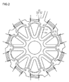
- FIG. 2 illustrates the step of filling the insertion holes 14 with the magnet material and the step of orienting and magnetizing the magnet material according to the present embodiment.
- a magnetic field is applied in the radial direction of the core 12 by a magnetizing device 20 while the insertion holes 14 are being filled with a magnet material 16c.
- the filling step and the orienting/magnetizing step overlap each other on the time axis.
- a magnetic field is therefore sequentially applied to the magnet material 16c having been introduced into the insertion holes 14.
- the magnetizing device 20 includes the same number of teeth 22 as the number of magnetic poles, and each tooth 22 has a coil 24 wound therearound. A current is applied to the coil 24 to use the teeth 22 as electromagnets.
- FIG. 3 shows a sectional configuration of a part of the rotor 10 produced by the steps illustrated in FIG. 2 .
- FIG. 3 shows a magnetic path Lmf formed by the orienting/magnetizing step using the magnetizing device 20 in FIG. 2 and passing through the core 12 etc.
- the permanent magnet 16 forming a single magnetic pole is formed by joining a first portion 16a and a second portion 16b at a connection CS.
- the first and second portions 16a, 16b extend from the outer side toward the inner side in the radial direction of the core 12, and the connection CS is located on the inner side in the radial direction of the core 12.
- magnetic flux passes through the magnetic path Lmf shown in FIG. 3 in the orienting/magnetizing step illustrated in FIG. 2 , whereby the magnet material is oriented and magnetized in accordance with the magnetic path Lmf.
- orientation direction MO is schematically shown by arrows in the first and second portions 16a, 16b.
- orientation means orienting the easy magnetization directions of the magnetic particles of the permanent magnet 16 in the same direction
- orientation direction refers to the direction parallel to the magnetic moment of the permanent magnet 16 after magnetization.
- the outermost end faces ES of the first and second portions 16a, 16b in the radial direction of the core 12 are shaped to extend in the orientation direction MO in section perpendicular to the axial direction Da.
- the lengths of the first and second portions 16a, 16b in the orientation direction MO are therefore substantially constant even near the end faces ES.
- the outside diameter of the core 12 gradually increases from the boundaries BL between a single magnetic pole (N pole in FIG. 3 ) formed by the first and second portions 16a, 16b and a pair of magnetic poles (S poles in FIG. 3 ) adjoining the single magnetic pole toward the middle of the single magnetic pole in the circumferential direction of the core 12.
- the distance between each of the end faces ES of the first and second portions 16a, 16b and the outer periphery of the core 12 is substantially constant.
- a long dashed double-short dashed line represents a part of a circle having a predetermined radius from the center of the core 12.
- the rotor 10 has the shape of a flower having the same number of petals as the number of magnetic poles (in this example, 10) as viewed in plan.
- the insertion holes 14 of the core 12 are formed in advance to define the end faces ES of the permanent magnets 16 shown in FIG. 3 .
- the insertion holes 14 are filled with the magnet material 16c and a magnetic field is applied to the magnet material 16c in the insertion holes 14 to produce the permanent magnets 16.
- the magnetic field is applied to the magnet material 16c along the magnetic path Lmf shown in FIG. 3 .
- the orientation directions MO near the end faces ES of the first and second portions 16a, 16b are therefore the directions along the end faces ES in section perpendicular to the axial direction Da.
- the present embodiment has the following effects.
- FIG. 4 shows magnetic flux density distribution according to the present embodiment.
- FIG. 6 shows magnetic flux density distribution of a comparative example shown in FIG. 5 .
- the outside diameter of a core 112 gradually increases from the portions facing the outer ends of an inner peripheral surface 116d of a permanent magnet 116 in the radial direction of the core 112 toward the middle of the core 112 in the circumferential direction.
- the outer periphery of the core 112 has the shape of an arc of a circle with constant curvature in the portions facing the outer ends of the permanent magnet 116 in the radial direction of the core 112.
- each of the outermost end faces of the permanent magnet 116 in the radial direction of the core 112 and the arc is substantially constant as viewed in section perpendicular to the axial direction Da.
- the outermost end faces of the permanent magnet 116 in the radial direction of the core 112 do not extend in the orientation direction as viewed in section perpendicular to the axial direction Da. In this case, the magnetic flux density distribution is significantly shifted from the fundamental waveform.
- FIG. 7 shows a sectional shape of the permanent magnet 16 according to the present embodiment.
- the length of the permanent magnet 16 in the orientation direction (the thickness of the permanent magnet 16) of the present embodiment gradually decreases toward the inner side in the radial direction of the core 12 except for a round portion UR near the connection CS.
- the shape of the permanent magnet 16 of the first embodiment is shown by a dashed line in FIG. 7 .
- the shape of the permanent magnet having a substantially constant length in the orientation direction except for the round portion UR is shown by the dashed line in FIG. 7 .
- the permanent magnets 16 according to the present embodiment are shaped to improve the orientation rate and the magnetization rate thereof.
- orientation rate refers to the degree to which the easy magnetization directions are oriented in the direction parallel to the magnetic moment required for the permanent magnet 16. If the orientation rate is low, the magnetic flux flowing from the N pole to the S pole as a result of magnetization has lower density.
- magnetization rate refers to the degree to which the magnetic moment (magnetization direction) in a local area (magnetic domain) in the permanent magnet 16 is oriented in one direction.
- the present embodiment aims to increase the speed electromotive force coefficient of the IPMSM by increasing not only the magnetization rate but also the orientation rate and thus to increase torque that is generated by the IPMSM when a current of a predetermined magnitude is applied thereto.
- the insertion holes 14 of the core 12 are filled with the magnet material 16c by injection molding, and a magnetic field is applied to the magnet material 16c in the insertion holes 14 by the magnetizing device 20 shown in FIG. 2 .
- the magnetic flux is less likely to enter the inner part of the magnet material 16c in the radial direction of the core 12 as compared to the outer part of the magnet material 16c in the radial direction of the core 12.
- the magnetic resistance of a magnetic path going from the magnetizing device 20 and returning to the magnetizing device 20 through the inner part of the magnet material 16c in the radial direction of the core 12 is higher than that of a magnetic path going from the magnetizing device 20 and returning to the magnetizing device 20 through the outer part of the magnet material 16c in the radial direction of the core 12.
- torque that is generated is small for the amount of magnet material 16c used. Namely, the efficiency of utilization of the magnet material 16c is reduced.
- each permanent magnet 16 is reduced in thickness toward the inner side in the radial direction of the core 12 in order to compensate for the fact that the magnetic resistance of the magnetic path going from the magnetizing device 20 and returning to the magnetizing device 20 through the inner part of the magnet material 16c in the radial direction of the core 12 is higher than that of the magnetic path going from the magnetizing device 20 and returning to the magnetizing device 20 through the outer part of the magnet material 16c in the radial direction of the core 12 due to the former magnetic path being longer than the latter magnetic path.
- This can be implemented because the magnet material 16c has lower magnetic permeability than the core 12.
- the present embodiment has the following effects in addition to the above effects (1) to (3) of the first embodiment.
- each permanent magnet 16 Since the thickness of each permanent magnet 16 is smaller on the inner side in the radial direction of the core 12 than on the outer side in the radial direction of the core 12, the surface area of the permanent magnet 16 can be increased as compared to the case where the permanent magnet 16 has a constant thickness. The magnetic flux of each permanent magnet 16 can therefore be easily increased.
- each permanent magnet 16 on the inner side in the radial direction of the core 12 can reduce the amount of magnet material 16c that is used for a single rotor 10. Reduction in cost can therefore be achieved.
- Increasing the thickness of each permanent magnet 16 on the outer side in the radial direction of the core 12, namely on the side that tends to be subjected to a reverse magnetic field when the IPMSM is being driven, can restrain demagnetization.
- the first portion 16a and the second portion 16b need not necessarily be connected together on the inner side in the radial direction of the core 12.
- the first portion 16a and the second portion 16b may be separated from each other.
- the shape of the permanent magnet having the first and second portions 16a, 16b separated from each other is not limited to a bisected U-shape.
- such a permanent magnet may have a bisected V-shape or a bisected angular U-shape.
- the permanent magnets are not limited to those produced by magnetizing a magnet material after filling the core 12 with the magnet material.
- sintered magnets that have been magnetized in advance may be placed in the core 12.
- demagnetization can be restrained as long as the outer end faces ES of the first and second portions 16a, 16b of a single magnetic pole in the radial direction of the core 12 extend in the orientation direction as viewed in section perpendicular to the axial direction Da.
- the core is not limited to the one shaped such that the outside diameter of the core gradually increases from the boundaries BL between adjoining ones of the magnetic poles toward the middle of each magnetic pole in the circumferential direction of the core as shown in FIG. 3 .
- the core may be shaped such that, only in the portions facing the end faces ES of the first and second portions 16a, 16b, the outside diameter of the core gradually increases toward the middle of each magnetic pole in the circumferential direction of the core, and the outside diameter of the core is constant in the portion located between the portions facing the end faces ES of the first and second portions 16a, 16b.
- the core may have a columnar shape, and clearance serving as a flux barrier may be provided between the core and each of the end faces ES of the first and second portions 16a, 16b so that the core does not contact the end faces ES of the first and second portions 16a, 16b.
- the core is not limited to the one formed by electrical steel sheets such as silicon steel sheets.
- the core may be made of spheroidal graphite cast iron (FCD), soft iron, etc.
- the permanent magnets 16 are not limited to those formed by injection molding.
- the permanent magnets 16 may be formed by compression molding. This can be implemented by introducing resin-coated magnetic particles used as a magnet material into the insertion holes 14 and compressing the magnet material in the insertion holes 14 to fill the insertion holes 14 with the magnet material, and applying a magnetic field in the radial direction of the core 12.
- a magnetic field is applied in the radial direction of the core 12
- demagnetization tends to occur if the permanent magnets 16 have a shorter length in the orientation direction in their ends in the radial direction of the core 12. It is therefore effective to form the permanent magnets 16 such that the end faces ES of the first and second portions 16a, 16b extend in the orientation direction as viewed in section perpendicular to the axial direction Da.
- FIG. 8 shows an example in which a core 212 has a columnar shape and each permanent magnet 216 is shaped such that its outer end faces in the radial direction of the core 212 extend along the outer periphery of the core 212 as in conventional examples.
- the magnetization rate and the orientation rate are improved particularly by adjusting the length of each permanent magnet 216 in the orientation direction.
- the magnet thickness t namely the length of the permanent magnet 216 in the orientation direction at the length x along the outer periphery of the permanent magnet 216 as measured from the connection CS between first and second portions 216a, 216b, is given by the following expression (c1) using the length L along the outer periphery of the permanent magnet 216 from the connection CS and the minimum length in the "orientation direction (minimum thickness c) of the permanent magnet 216.
- t c + b / 1 + exp ⁇ a ⁇ x + h ⁇ L / 2 Coefficient a and constants b, c are used in the expression (c1).
- Constant b is set to about the maximum length in the orientation direction (maximum thickness) minus the minimum thickness c.
- FIG. 9 shows the relationship between the length x along the outer periphery of the permanent magnet 216 and the magnet thickness t as defined by the expression (c1).
- the magnet thickness t transitions from the maximum thickness of about "c + b" to the minimum thickness c.
- the length x along the outer periphery of the permanent magnet 216 at which the magnet thickness t becomes equal to an intermediate thickness between the maximum thickness and the minimum thickness can be adjusted by constant h.
- constant h has been adjusted so that the magnet thickness t becomes equal to the intermediate thickness between the maximum thickness and the minimum thickness when the length x along the outer periphery of the permanent magnet 216 is about L/2.
- constant h is adjusted so that the magnet thickness t becomes equal to the intermediate thickness between the maximum thickness and the minimum thickness at a position near the outer periphery of the core 212.
- the magnet thickness t converges to "c + b" when the length x is large, and converges to the minimum thickness c when the length x is small.
- coefficient a is increased, the absolute value of the rate of change from one of a value close to "c” and a value close to "c + b" to the other increases.
- each permanent magnet may be shaped like a permanent magnet 316 in a core 312 as shown in FIG. 10.
- FIG. 11 shows the relationship between the length x along the outer periphery of the permanent magnet 316 and the magnet thickness t.
- Setting of the magnet thickness t shown in FIGS. 8 and 10 may be applied to the configuration in which the end faces of each permanent magnet extend in the orientation direction as viewed in section perpendicular to the axial direction Da as in the above embodiments.
- the core may be shaped as described in the above embodiments or their modifications.
- the magnetizing device 20 is not limited to the one using electromagnets.
- the magnetizing device 20 may use permanent magnets.
- the IPMSM is not limited to the one contained in an EPS.
- the IPMSM may be contained in a variable gear ratio steering system.
- the IPMSM is not limited to the one contained in an actuator for steering steered wheels.
Landscapes
- Engineering & Computer Science (AREA)
- Power Engineering (AREA)
- Manufacturing & Machinery (AREA)
- Permanent Field Magnets Of Synchronous Machinery (AREA)
- Iron Core Of Rotating Electric Machines (AREA)
- Manufacture Of Motors, Generators (AREA)
- Permanent Magnet Type Synchronous Machine (AREA)
Abstract
Description
- The present invention relates to interior permanent magnet rotors having permanent magnets embedded in a core and methods for manufacturing the same.
- For example, United States Patent Application Publication No.
2015/0137629 describes a rotor including permanent magnets extending from the outer side toward the inner side in the radial direction of a core. - In one possible manufacturing process of this rotor, insertion holes are formed in the core, and a magnetic field is applied from the outside of the core in the radial direction to a material of the permanent magnets (magnet material) filling the insertion holes. In this case, a magnetic path in the magnet material may decrease in the outer ends of the magnet material in the radial direction of the core. If the magnetic path in the magnet material decreases in the outer ends of the magnet material in the radial direction of the core, the permanent magnets have a shorter length in the orientation direction in their outer ends in the radial direction of the core. When an electric motor is driven, the outer parts of the permanent magnets in the radial direction of the core tend to be subjected to a reverse magnetic field opposite to that of the magnetic flux of the permanent magnets. When subjected to the reverse magnetic field, the permanent magnets are more likely to be demagnetized as their length in the orientation direction is shorter. Accordingly, in the case where the permanent magnets have a shorter length in the orientation direction in their ends in the radial direction of the core as described above, the permanent magnets tend to be demagnetized while the rotor is in use.
- It is one object of the present invention to provide an interior permanent magnet rotor that can restrain demagnetization of permanent magnets embedded in a core, and a method for manufacturing the same.
- According to one aspect of the present invention, an interior permanent magnet rotor includes: a core made of a soft magnetic material; and a permanent magnet embedded in the core. The permanent magnet includes a first portion and a second portion each extending from an outer side toward an inner side in a radial direction of the core. The first portion and the second portion adjoin each other. The first portion and the second portion form a single magnetic pole. An orientation direction in outer ends of the first and second portions of the single magnetic pole in the radial direction of the core is such a direction that goes further away from a center of the core toward a middle of the single magnetic pole in a circumferential direction of the core. Outermost end faces of the first and second portions in the radial direction of the core extend in the orientation direction of the permanent magnet as viewed in section perpendicular to an axial direction of the core.
- If the permanent magnet is shaped such that the end faces of the first and second portions are not parallel to the orientation direction as viewed in section perpendicular to the axial direction of the core, the length of the permanent magnet in the orientation direction decreases near the end faces of the first and second portions. Demagnetization tends to occur if the length in the orientation direction is short. However, if the permanent magnet is shaped such that the end faces of the first and second portions are close to parallel to the orientation direction as viewed in section perpendicular to the axial direction of the core, the length of the permanent magnet in the orientation direction does not excessively decrease even near the end faces of the first and second portions as compared to the parts of the permanent magnet which are located slightly away from the end faces of the first and second portions. In the above configuration, the outer end faces of the permanent magnet in the radial direction of the core extend in the orientation direction of the permanent magnet as viewed in section perpendicular to the axial direction of the core. This can restrain demagnetization of the permanent magnet embedded in the core.
- In the interior permanent magnet rotor of the above aspect, an outside diameter of the core may gradually increase from portions of the core which face the outermost end faces of the first and second portions in the radial direction of the core toward the middle of the single magnetic pole in the circumferential direction of the core.
- In the above configuration, the orientation direction in the outer ends of the first and second portions of the single magnetic pole in the radial direction of the core is such a direction that goes further away from the center of the core toward the middle of the single magnetic pole in the circumferential direction of the core. The outer end faces of the first and second portions in the radial direction of the core therefore extend further away from the center of the core toward the middle of the single magnetic pole in the circumferential direction of the core, as viewed in section perpendicular to the axial direction of the core. If the outer diameter of the core is constant, the distance between each of the outer end faces of the first and second portions in the radial direction of the core and the outer periphery of the core increases as further away from the middle of the single magnetic pole in the circumferential direction of the core. In each of the first and second portions, a pair of opposite surfaces in the circumferential direction of the core have different polarities from each other. The portions of the core which face the outermost end faces of the first and second portions form short circuit paths connecting one of the pair of surfaces which forms the magnetic pole, namely the surface located near the middle of the magnetic pole in the circumferential direction of the core, to the other surface without passing through a stator. The amount of magnetic flux in the short circuit paths increases as the distance between each of the outer end faces of the first and second portions in the radial direction of the core and the outer periphery of the core increases, namely as the width of a path serving as a magnetic path for leakage flux increases.
- In the above configuration, the outside diameter of the core gradually increases from the portions of the core which face the outermost end faces of the first and second portions in the radial direction of the core toward the middle of the single magnetic pole in the circumferential direction of the core. This can suppress the distance between each of the outer ends of the first and second portions in the radial direction of the core and the outer periphery of the core from increasing partially, and can reduce the amount of magnetic flux in the short circuit paths.
- In the interior permanent magnet rotor of the above aspect, the outside diameter of the core may gradually increase from boundaries between the single magnetic pole and magnetic poles adjoining the single magnetic pole on both sides toward the middle of the single magnetic pole in the circumferential direction of the core.
- In the above configuration, the outside diameter of the core gradually increases from the boundaries between the single magnetic pole and the magnetic poles adjoining the single magnetic pole on both sides toward the middle of the single magnetic pole in the circumferential direction of the core. This makes it easy to collect magnetic flux leaving the first portion and the second portion and magnetic flux entering the first portion and the second portion in the middle part of the single magnetic pole in the core. It is therefore easy to produce magnetic flux with a fundamental waveform having a maximum value of magnetic flux density in the middle part of the magnetic pole, and space harmonics of the magnetic flux can be reduced.
- In the interior permanent magnet rotor of the above aspect, a length of the permanent magnet in the orientation direction may be shorter on the inner side in the radial direction of the core than on the outer side in the radial direction of the core. In the above configuration, since the length of the permanent magnet in the orientation direction is shorter on the inner side in the radial direction of the core than on the outer side in the radial direction of the core, the surface area of the permanent magnet can be increased, and the magnetic flux of the permanent magnet can be easily increased. In the case where the permanent magnet is produced by applying a magnetic field to a magnet material after filling the core with the magnet material, a magnetic path passing through the magnet material on the inner side in the radial direction of the core tends to have higher magnetic resistance than a magnetic path passing through the magnet material on the outer side in the radial direction of the core, if the permanent magnet has a constant length in the orientation direction. In this case, the amount of magnetic flux passing through the magnet material on the inner side in the radial direction of the core tends to be small. In the above configuration, however, the length of the permanent magnet in the orientation direction is shorter on the inner side in the radial direction of the core than on the outer side in the radial direction of the core. This can reduce the magnetic resistance in the magnetic path passing through the magnet material on the inner side in the radial direction of the core, and can therefore restrain a decrease in magnetic flux passing through the magnet material on the inner side in the radial direction of the core.
- According to another aspect of the invention, a method for manufacturing the interior permanent magnet rotor of the above aspect includes: filling an insertion hole of the core with a magnet material that is a material of the permanent magnet; and orienting/magnetizing by applying a magnetic field to the magnet material in the insertion hole in the radial direction of the core.
- In the above configuration, the magnetic field is applied in the radial direction of the core to the magnet material filling the insertion hole of the core. Accordingly, the orientation direction in the outer ends of the first and second portions of the single magnetic pole in the radial direction of the core tends to be such a direction that goes further away from the center of the core toward the middle of the single magnetic pole in the circumferential direction of the core. That is, the orientation direction in the outer ends of the first and second portions of the single magnetic pole in the radial direction of the core tends to be the orientation direction of the permanent magnet in the inner permanent magnet rotor of the above aspect. The inner permanent magnet rotor of the above aspect can restrain a decrease in magnetic flux passing through the magnet material on the inner side in the radial direction of the core by the orienting/magnetizing. Accordingly, an orientation rate and a magnetization rate can be improved, and efficiency of utilization of the permanent magnet can be improved.
- The foregoing and further features and advantages of the invention will become apparent from the following description of example embodiments with reference to the accompanying drawings, wherein like numerals are used to represent like elements and wherein:
-
FIG. 1 is a plan view of an interior permanent magnet rotor according to a first embodiment; -
FIG. 2 is a plan view illustrating a filling step and an orienting/magnetizing step according to the embodiment; -
FIG. 3 is a partial sectional view of the rotor according to the embodiment; -
FIG. 4 is a graph showing magnetic flux density distribution according to the embodiment; -
FIG. 5 is a diagram showing the shape of a part of a rotor of a comparative example; -
FIG. 6 is a graph showing magnetic flux density distribution of the comparative example; -
FIG. 7 is a partial enlarged view of a rotor according to a second embodiment; -
FIG. 8 is a diagram showing an example of the shape of a permanent magnet that can improve the magnetization rate and the orientation rate; -
FIG. 9 is a graph showing the thickness of the permanent magnet; -
FIG. 10 is a diagram showing another example of the shape of a permanent magnet that can improve the magnetization rate and the orientation rate; and -
FIG. 11 is a graph showing the thickness of the permanent magnet. - A first embodiment of an interior permanent magnet rotor will be described with reference to the accompanying drawings. A
rotor 10 shown inFIG. 1 is contained in an interior permanent magnet synchronous motor (IPMSM). The IPMSM forms an electric power steering system (EPS). Therotor 10 includes acore 12 andpermanent magnets 16. Thecore 12 is made of a soft magnetic material. Thecore 12 is formed by stacking a plurality of electrical steel sheets that are silicon steel sheets, and has a function as a magnetic circuit and a function to hold thepermanent magnets 16 and to generate and transmit rotational torque. Thecore 12 has 10 insertion holes 14. The insertion holes 14 extend through the core 12 in the axial direction Da of thecore 12. Eachinsertion hole 14 has a substantially U-shape in section perpendicular to the axial direction Da. The insertion holes 14 are disposed evenly in the circumferential direction Dc of thecore 12. Thecore 12 has thepermanent magnets 16 embedded in the insertion holes 14. A mixture of magnetic particles and resin is used as a magnet material for thepermanent magnets 16. Thepermanent magnets 16 are produced by magnetizing the magnet material. The outer periphery of therotor 10 has such a sectional shape as shown inFIG. 1 at any position in the axial direction Da. - In the present embodiment, the
permanent magnets 16 are produced by filling the insertion holes 14 with the magnet material by injection molding using thecore 12 as a mold, and applying a magnetic field to the magnet material in the insertion holes 14. -
FIG. 2 illustrates the step of filling the insertion holes 14 with the magnet material and the step of orienting and magnetizing the magnet material according to the present embodiment. In the present embodiment, a magnetic field is applied in the radial direction of the core 12 by a magnetizingdevice 20 while the insertion holes 14 are being filled with amagnet material 16c. Namely, in the present embodiment, the filling step and the orienting/magnetizing step overlap each other on the time axis. A magnetic field is therefore sequentially applied to themagnet material 16c having been introduced into the insertion holes 14. The magnetizingdevice 20 includes the same number ofteeth 22 as the number of magnetic poles, and eachtooth 22 has acoil 24 wound therearound. A current is applied to thecoil 24 to use theteeth 22 as electromagnets. -
FIG. 3 shows a sectional configuration of a part of therotor 10 produced by the steps illustrated inFIG. 2 .FIG. 3 shows a magnetic path Lmf formed by the orienting/magnetizing step using the magnetizingdevice 20 inFIG. 2 and passing through the core 12 etc. - As shown in
FIG. 3 , thepermanent magnet 16 forming a single magnetic pole is formed by joining afirst portion 16a and asecond portion 16b at a connection CS. The first andsecond portions core 12. In the first andsecond portions FIG. 3 in the orienting/magnetizing step illustrated inFIG. 2 , whereby the magnet material is oriented and magnetized in accordance with the magnetic path Lmf. InFIG. 3 , the orientation direction MO is schematically shown by arrows in the first andsecond portions permanent magnet 16 in the same direction, and the term "orientation direction" refers to the direction parallel to the magnetic moment of thepermanent magnet 16 after magnetization. - In the present embodiment, the outermost end faces ES of the first and
second portions second portions - The outside diameter of the core 12 gradually increases from the boundaries BL between a single magnetic pole (N pole in
FIG. 3 ) formed by the first andsecond portions FIG. 3 ) adjoining the single magnetic pole toward the middle of the single magnetic pole in the circumferential direction of thecore 12. In particular, the distance between each of the end faces ES of the first andsecond portions core 12 is substantially constant. InFIG. 3 , a long dashed double-short dashed line represents a part of a circle having a predetermined radius from the center of thecore 12. As shown inFIG. 1 , therotor 10 has the shape of a flower having the same number of petals as the number of magnetic poles (in this example, 10) as viewed in plan. - Functions of the present embodiment will be described. The insertion holes 14 of the core 12 are formed in advance to define the end faces ES of the
permanent magnets 16 shown inFIG. 3 . As shown inFIG. 2 , the insertion holes 14 are filled with themagnet material 16c and a magnetic field is applied to themagnet material 16c in the insertion holes 14 to produce thepermanent magnets 16. At this time, the magnetic field is applied to themagnet material 16c along the magnetic path Lmf shown inFIG. 3 . The orientation directions MO near the end faces ES of the first andsecond portions - The present embodiment has the following effects.
- (1) The outermost end faces ES of the first and
second portions permanent magnet 16 in section perpendicular to the axial direction Da. The length of eachpermanent magnet 16 in the orientation direction MO therefore does not excessively decrease near the end faces ES as compared to the parts of thepermanent magnet 16 which are located slightly away from the end faces ES. Accordingly, demagnetization of thepermanent magnets 16 embedded in the core 12 can be restrained. - (2) The
core 12 is shaped such that the outside diameter of the core 12 gradually increases from the end portions of each magnetic pole in the circumferential direction of the core 12 toward the middle of the magnetic pole in the circumferential direction of thecore 12. Accordingly, as opposed to the case where the outer peripheral portions of the core 12 which face the first andsecond portions second portions core 12 and the outer periphery of thecore 12 does not increase toward the outer side each magnetic pole in the circumferential direction. In the case where the distance between each of the radially outer end faces ES of the first andsecond portions peripheral surface 16d and an outerperipheral surface 16e of eachpermanent magnet 16 inFIG. 3 without passing through a stator coil. - (3) The outside diameter of the core 12 gradually increases from the boundaries BL between a single magnetic pole and magnetic poles adjoining the single magnetic pole on both sides toward the middle of the single magnetic pole in the circumferential direction of the
core 12. This makes it easy to collect the magnetic flux leaving thefirst portion 16a and thesecond portion 16b and the magnetic flux entering thefirst portion 16a and thesecond portion 16b in the middle part of the single magnetic pole in thecore 12. It is therefore easy to produce the magnetic flux with a fundamental waveform having a maximum value of the magnetic flux density in the middle part of the magnetic pole, and space harmonics of the magnetic flux can be reduced. -
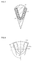
FIG. 4 shows magnetic flux density distribution according to the present embodiment.FIG. 6 shows magnetic flux density distribution of a comparative example shown inFIG. 5 . In the comparative example shown inFIG. 5 , the outside diameter of a core 112 gradually increases from the portions facing the outer ends of an innerperipheral surface 116d of apermanent magnet 116 in the radial direction of the core 112 toward the middle of the core 112 in the circumferential direction. However, the outer periphery of thecore 112 has the shape of an arc of a circle with constant curvature in the portions facing the outer ends of thepermanent magnet 116 in the radial direction of thecore 112. The distance between each of the outermost end faces of thepermanent magnet 116 in the radial direction of thecore 112 and the arc is substantially constant as viewed in section perpendicular to the axial direction Da. Namely, the outermost end faces of thepermanent magnet 116 in the radial direction of the core 112 do not extend in the orientation direction as viewed in section perpendicular to the axial direction Da. In this case, the magnetic flux density distribution is significantly shifted from the fundamental waveform. - A second embodiment will be described with reference to the drawings. The differences from the first embodiment will be mainly described below.
-
FIG. 7 shows a sectional shape of thepermanent magnet 16 according to the present embodiment. - As shown in
FIG. 7 , the length of thepermanent magnet 16 in the orientation direction (the thickness of the permanent magnet 16) of the present embodiment gradually decreases toward the inner side in the radial direction of the core 12 except for a round portion UR near the connection CS. For comparison, the shape of thepermanent magnet 16 of the first embodiment is shown by a dashed line inFIG. 7 . In other words, the shape of the permanent magnet having a substantially constant length in the orientation direction except for the round portion UR is shown by the dashed line inFIG. 7 . - The
permanent magnets 16 according to the present embodiment are shaped to improve the orientation rate and the magnetization rate thereof. As used herein, the term "orientation rate" refers to the degree to which the easy magnetization directions are oriented in the direction parallel to the magnetic moment required for thepermanent magnet 16. If the orientation rate is low, the magnetic flux flowing from the N pole to the S pole as a result of magnetization has lower density. The term "magnetization rate" refers to the degree to which the magnetic moment (magnetization direction) in a local area (magnetic domain) in thepermanent magnet 16 is oriented in one direction. Even if the orientation rate is high, the magnetic flux flowing from the N pole to the S pole of thepermanent magnet 16 has lower density if the degree to which the magnetization direction is oriented in one of the pair of easy magnetization direction is low. The present embodiment aims to increase the speed electromotive force coefficient of the IPMSM by increasing not only the magnetization rate but also the orientation rate and thus to increase torque that is generated by the IPMSM when a current of a predetermined magnitude is applied thereto. - In the present embodiment, as in the first embodiment, the insertion holes 14 of the core 12 are filled with the
magnet material 16c by injection molding, and a magnetic field is applied to themagnet material 16c in the insertion holes 14 by the magnetizingdevice 20 shown inFIG. 2 . In this case, the magnetic flux is less likely to enter the inner part of themagnet material 16c in the radial direction of the core 12 as compared to the outer part of themagnet material 16c in the radial direction of thecore 12. One reason for this is that the magnetic resistance of a magnetic path going from the magnetizingdevice 20 and returning to the magnetizingdevice 20 through the inner part of themagnet material 16c in the radial direction of thecore 12 is higher than that of a magnetic path going from the magnetizingdevice 20 and returning to the magnetizingdevice 20 through the outer part of themagnet material 16c in the radial direction of thecore 12. In the case where thepermanent magnet 16 has a low orientation rate and a low magnetization rate on the inner side in the radial direction of the core 12, torque that is generated is small for the amount ofmagnet material 16c used. Namely, the efficiency of utilization of themagnet material 16c is reduced. - In the present embodiment, each
permanent magnet 16 is reduced in thickness toward the inner side in the radial direction of the core 12 in order to compensate for the fact that the magnetic resistance of the magnetic path going from the magnetizingdevice 20 and returning to the magnetizingdevice 20 through the inner part of themagnet material 16c in the radial direction of thecore 12 is higher than that of the magnetic path going from the magnetizingdevice 20 and returning to the magnetizingdevice 20 through the outer part of themagnet material 16c in the radial direction of thecore 12 due to the former magnetic path being longer than the latter magnetic path. This can be implemented because themagnet material 16c has lower magnetic permeability than thecore 12. - The present embodiment has the following effects in addition to the above effects (1) to (3) of the first embodiment.
- (4) The thickness of each permanent magnet 16 (length in the orientation direction) is smaller on the inner side in the radial direction of the core 12 than on the outer side in the radial direction of the
core 12. This configuration can reduce the magnetic resistance of the magnetic path going from the magnetizingdevice 20 and returning to the magnetizingdevice 20 through the inner part of themagnet material 16c in the radial direction of thecore 12 and can thus increase the magnetic flux passing through the inner part of themagnet material 16c in the radial direction of thecore 12. The orientation rate and the magnetization rate in the inner part of eachpermanent magnet 16 in the radial direction of the core 12 can therefore be improved. - Since the thickness of each
permanent magnet 16 is smaller on the inner side in the radial direction of the core 12 than on the outer side in the radial direction of the core 12, the surface area of thepermanent magnet 16 can be increased as compared to the case where thepermanent magnet 16 has a constant thickness. The magnetic flux of eachpermanent magnet 16 can therefore be easily increased. - Reducing the thickness of each
permanent magnet 16 on the inner side in the radial direction of the core 12 can reduce the amount ofmagnet material 16c that is used for asingle rotor 10. Reduction in cost can therefore be achieved. Increasing the thickness of eachpermanent magnet 16 on the outer side in the radial direction of the core 12, namely on the side that tends to be subjected to a reverse magnetic field when the IPMSM is being driven, can restrain demagnetization. - At least one of the matters of the above embodiments may be modified as follows.
- Regarding the shape of the permanent magnets, the
first portion 16a and thesecond portion 16b need not necessarily be connected together on the inner side in the radial direction of thecore 12. Thefirst portion 16a and thesecond portion 16b may be separated from each other. In this case, it is desirable to place a member with low magnetic permeability in contact with the inner ends of the first andsecond portions second portions core 12. The shape of the permanent magnet having the first andsecond portions - The permanent magnets are not limited to those produced by magnetizing a magnet material after filling the core 12 with the magnet material. For example, sintered magnets that have been magnetized in advance may be placed in the
core 12. In this case as well, demagnetization can be restrained as long as the outer end faces ES of the first andsecond portions - Regarding the shape of the core, the core is not limited to the one shaped such that the outside diameter of the core gradually increases from the boundaries BL between adjoining ones of the magnetic poles toward the middle of each magnetic pole in the circumferential direction of the core as shown in
FIG. 3 . For example, the core may be shaped such that, only in the portions facing the end faces ES of the first andsecond portions second portions - For example, the core may have a columnar shape, and clearance serving as a flux barrier may be provided between the core and each of the end faces ES of the first and
second portions second portions - Regarding the material of the core, the core is not limited to the one formed by electrical steel sheets such as silicon steel sheets. For example, the core may be made of spheroidal graphite cast iron (FCD), soft iron, etc.
- Regarding the manufacturing method, the
permanent magnets 16 are not limited to those formed by injection molding. For example, thepermanent magnets 16 may be formed by compression molding. This can be implemented by introducing resin-coated magnetic particles used as a magnet material into the insertion holes 14 and compressing the magnet material in the insertion holes 14 to fill the insertion holes 14 with the magnet material, and applying a magnetic field in the radial direction of thecore 12. In this case as well, since a magnetic field is applied in the radial direction of the core 12, demagnetization tends to occur if thepermanent magnets 16 have a shorter length in the orientation direction in their ends in the radial direction of thecore 12. It is therefore effective to form thepermanent magnets 16 such that the end faces ES of the first andsecond portions - Regarding the length of the permanent magnets in the orientation direction, the configuration in which the length of each
permanent magnet 16 in the orientation direction is smaller on the inner side in the radial direction of the core 12 than on the outer side in the radial direction of thecore 12 is not limited to the configuration of the second embodiment (FIG. 7). FIG. 8 shows an example in which acore 212 has a columnar shape and eachpermanent magnet 216 is shaped such that its outer end faces in the radial direction of thecore 212 extend along the outer periphery of the core 212 as in conventional examples. In this example, the magnetization rate and the orientation rate are improved particularly by adjusting the length of eachpermanent magnet 216 in the orientation direction. InFIG. 8 , the magnet thickness t, namely the length of thepermanent magnet 216 in the orientation direction at the length x along the outer periphery of thepermanent magnet 216 as measured from the connection CS between first andsecond portions permanent magnet 216 from the connection CS and the minimum length in the "orientation direction (minimum thickness c) of thepermanent magnet 216.

-
FIG. 9 shows the relationship between the length x along the outer periphery of thepermanent magnet 216 and the magnet thickness t as defined by the expression (c1). As shown inFIG. 9 , the magnet thickness t transitions from the maximum thickness of about "c + b" to the minimum thickness c. In this case, the length x along the outer periphery of thepermanent magnet 216 at which the magnet thickness t becomes equal to an intermediate thickness between the maximum thickness and the minimum thickness can be adjusted by constant h. InFIG. 9 , constant h has been adjusted so that the magnet thickness t becomes equal to the intermediate thickness between the maximum thickness and the minimum thickness when the length x along the outer periphery of thepermanent magnet 216 is about L/2. If it is desired to increase the magnet thickness t only near the outer periphery of thecore 212, constant h is adjusted so that the magnet thickness t becomes equal to the intermediate thickness between the maximum thickness and the minimum thickness at a position near the outer periphery of thecore 212. - In the expression (c1), the magnet thickness t converges to "c + b" when the length x is large, and converges to the minimum thickness c when the length x is small. However, if coefficient a is increased, the absolute value of the rate of change from one of a value close to "c" and a value close to "c + b" to the other increases.
- The method for improving the magnetization rate and the orientation rate by adjusting the length in the orientation direction of the
permanent magnet 216 is not limited to the one using the expression (c1). For example, each permanent magnet may be shaped like apermanent magnet 316 in acore 312 as shown inFIG. 10. FIG. 11 shows the relationship between the length x along the outer periphery of thepermanent magnet 316 and the magnet thickness t. - Setting of the magnet thickness t shown in
FIGS. 8 and10 may be applied to the configuration in which the end faces of each permanent magnet extend in the orientation direction as viewed in section perpendicular to the axial direction Da as in the above embodiments. In this case, the core may be shaped as described in the above embodiments or their modifications. - The magnetizing
device 20 is not limited to the one using electromagnets. For example, the magnetizingdevice 20 may use permanent magnets. - The IPMSM is not limited to the one contained in an EPS. For example, the IPMSM may be contained in a variable gear ratio steering system. The IPMSM is not limited to the one contained in an actuator for steering steered wheels.
Claims (5)
- An interior permanent magnet rotor, comprising:a core made of a soft magnetic material; anda permanent magnet embedded in the core, wherein,the permanent magnet includes a first portion and a second portion each extending from an outer side toward an inner side in a radial direction of the core,the first portion and the second portion adjoin each other,the first portion and the second portion form a single magnetic pole,an orientation direction in outer end portions of the first and second portions of the single magnetic pole in the radial direction of the core is such a direction that goes further away from a center of the core toward a middle of the single magnetic pole in a circumferential direction of the core, andoutermost end faces of the first and second portions in the radial direction of the core extend in the orientation direction of the permanent magnet as viewed in section perpendicular to an axial direction of the core.
- The interior permanent magnet rotor according to claim 1, wherein,
an outside diameter of the core gradually increases from portions of the core which face the outermost end faces of the first and second portions in the radial direction of the core toward the middle of the single magnetic pole in the circumferential direction of the core. - The interior permanent magnet rotor according to claim 2, wherein,
the outside diameter of the core gradually increases from boundaries between the single magnetic pole and magnetic poles adjoining the single magnetic pole on both sides toward the middle of the single magnetic pole in the circumferential direction of the core. - The interior permanent magnet rotor according to any one of claims 1 to 3, wherein,
a length of the permanent magnet in the orientation direction is shorter on the inner side in the radial direction of the core than on the outer side in the radial direction of the core. - A method for manufacturing the interior permanent magnet rotor according to any one of claims 1 to 4, comprising:filling an insertion hole of the core with a magnet material that is a material of the permanent magnet; andorienting/magnetizing by applying a magnetic field to the magnet material in the insertion hole in the radial direction of the core.
Applications Claiming Priority (1)
| Application Number | Priority Date | Filing Date | Title |
|---|---|---|---|
| JP2015175970A JP2017055493A (en) | 2015-09-07 | 2015-09-07 | Embedded magnet type rotor and manufacturing method of embedded magnet type rotor |
Publications (1)
| Publication Number | Publication Date |
|---|---|
| EP3139471A1 true EP3139471A1 (en) | 2017-03-08 |
Family
ID=56852194
Family Applications (1)
| Application Number | Title | Priority Date | Filing Date |
|---|---|---|---|
| EP16186836.9A Withdrawn EP3139471A1 (en) | 2015-09-07 | 2016-09-01 | Interior permanent magnet rotor and method for manufacturing the same |
Country Status (4)
| Country | Link |
|---|---|
| US (1) | US20170070111A1 (en) |
| EP (1) | EP3139471A1 (en) |
| JP (1) | JP2017055493A (en) |
| CN (1) | CN106505761A (en) |
Families Citing this family (8)
| Publication number | Priority date | Publication date | Assignee | Title |
|---|---|---|---|---|
| TWM576750U (en) | 2017-07-25 | 2019-04-11 | 美商米沃奇電子工具公司 | Electrical composition, electric device system, battery pack, electric motor, motor assembly and electric motor assembly |
| JP6992368B2 (en) * | 2017-09-27 | 2022-01-13 | 富士電機株式会社 | Variable magnetic flux type permanent magnet type rotary electric machine |
| GB201717871D0 (en) | 2017-10-30 | 2017-12-13 | Romax Tech Limited | Motor |
| CN108134491B (en) * | 2017-12-22 | 2019-11-12 | 上海电机系统节能工程技术研究中心有限公司 | A Design Method for Rotor Core of Permanent Magnet Synchronous Motor |
| US11780061B2 (en) | 2019-02-18 | 2023-10-10 | Milwaukee Electric Tool Corporation | Impact tool |
| JP7476679B2 (en) * | 2020-06-09 | 2024-05-01 | 株式会社デンソー | Rotor manufacturing apparatus, rotor manufacturing method and rotor |
| JP7543963B2 (en) * | 2021-03-26 | 2024-09-03 | 株式会社デンソー | Bonded magnet and its manufacturing method |
| JP7615847B2 (en) * | 2021-04-05 | 2025-01-17 | 株式会社デンソー | Rotor and rotating electric machine |
Citations (7)
| Publication number | Priority date | Publication date | Assignee | Title |
|---|---|---|---|---|
| US20020047434A1 (en) * | 2000-08-29 | 2002-04-25 | Haruo Koharagi | Permanent magnet rotating electric machine |
| JP2009005445A (en) * | 2007-06-20 | 2009-01-08 | Kura Gijutsu Kenkyusho:Kk | Field-controlled electromagnetic rotation system |
| US20130119811A1 (en) * | 2011-11-16 | 2013-05-16 | Shin-Etsu Chemical Co., Ltd. | Rotor and permanent magnetic rotating machine |
| WO2013103118A1 (en) * | 2012-01-06 | 2013-07-11 | 愛知製鋼株式会社 | Internal magnet-type synchronous machine and rotor therefor |
| US20130313936A1 (en) * | 2012-05-25 | 2013-11-28 | Jtekt Corporation | Rotor and motor including rotor |
| US20150137629A1 (en) | 2013-11-18 | 2015-05-21 | Steering Solutions Ip Holding Corporation | Low cost permanent magnet motor for an electric power steering system |
| JP2015133839A (en) * | 2014-01-14 | 2015-07-23 | 株式会社ジェイテクト | Magnet-embedded rotor |
Family Cites Families (5)
| Publication number | Priority date | Publication date | Assignee | Title |
|---|---|---|---|---|
| DE10318624A1 (en) * | 2003-04-24 | 2004-11-25 | Minebea Co., Ltd. | Rotor body for an electric motor |
| WO2008113082A1 (en) * | 2007-03-15 | 2008-09-18 | A.O. Smith Corporation | Interior permanent magnet motor including rotor with flux barriers |
| WO2012105656A1 (en) * | 2011-02-04 | 2012-08-09 | 三菱電機株式会社 | Embedded permanent magnet type rotating electrical machine for vehicle |
| JP6033424B2 (en) * | 2012-06-26 | 2016-11-30 | 日産自動車株式会社 | Variable magnetomotive force type rotating electrical machine and control device for variable magnetomotive force type rotating electrical machine |
| JP2014155415A (en) * | 2013-02-13 | 2014-08-25 | Jtekt Corp | Embedded magnet rotor and method of manufacturing embedded magnet rotor |
-
2015
- 2015-09-07 JP JP2015175970A patent/JP2017055493A/en active Pending
-
2016
- 2016-08-25 US US15/247,327 patent/US20170070111A1/en not_active Abandoned
- 2016-08-30 CN CN201610766360.1A patent/CN106505761A/en active Pending
- 2016-09-01 EP EP16186836.9A patent/EP3139471A1/en not_active Withdrawn
Patent Citations (7)
| Publication number | Priority date | Publication date | Assignee | Title |
|---|---|---|---|---|
| US20020047434A1 (en) * | 2000-08-29 | 2002-04-25 | Haruo Koharagi | Permanent magnet rotating electric machine |
| JP2009005445A (en) * | 2007-06-20 | 2009-01-08 | Kura Gijutsu Kenkyusho:Kk | Field-controlled electromagnetic rotation system |
| US20130119811A1 (en) * | 2011-11-16 | 2013-05-16 | Shin-Etsu Chemical Co., Ltd. | Rotor and permanent magnetic rotating machine |
| WO2013103118A1 (en) * | 2012-01-06 | 2013-07-11 | 愛知製鋼株式会社 | Internal magnet-type synchronous machine and rotor therefor |
| US20130313936A1 (en) * | 2012-05-25 | 2013-11-28 | Jtekt Corporation | Rotor and motor including rotor |
| US20150137629A1 (en) | 2013-11-18 | 2015-05-21 | Steering Solutions Ip Holding Corporation | Low cost permanent magnet motor for an electric power steering system |
| JP2015133839A (en) * | 2014-01-14 | 2015-07-23 | 株式会社ジェイテクト | Magnet-embedded rotor |
Also Published As
| Publication number | Publication date |
|---|---|
| CN106505761A (en) | 2017-03-15 |
| US20170070111A1 (en) | 2017-03-09 |
| JP2017055493A (en) | 2017-03-16 |
Similar Documents
| Publication | Publication Date | Title |
|---|---|---|
| US20170070111A1 (en) | Interior Permanent Magnet Rotor and Method for Manufacturing the Same | |
| JP5961344B2 (en) | Magnetic flux concentrating type synchronous rotating electrical machine with permanent magnet | |
| US7902707B2 (en) | Anisotropic permanent magnet motor | |
| EP1164683B1 (en) | Permanent magnet rotor and method of making the same | |
| JP6215041B2 (en) | motor | |
| US20150288233A1 (en) | Rotor and motor using the same | |
| CN103959607B (en) | electric motor | |
| US10566859B2 (en) | Rotor | |
| CN102257702A (en) | Permanent magnet type rotary electric machine | |
| CN110086274A (en) | Permanent magnetic baried type motor and its manufacturing method | |
| KR20140094516A (en) | Rotor for a rotating electric machine, and rotating electric machine comprising such a rotor | |
| JPH1051984A (en) | Permanent magnet synchronous motor | |
| JP2014155415A (en) | Embedded magnet rotor and method of manufacturing embedded magnet rotor | |
| CN103959608A (en) | Rotor for a rotary electric machine and rotary electric machine comprising such a rotor | |
| EP3012947A2 (en) | Method for manufacturing an interior permanent magnet rotor unit and magnetizing device | |
| US12323005B2 (en) | Rotor and method for manufacturing rotor | |
| CN112491178A (en) | Adhesive mixture including hard magnetic material for motor rotors | |
| EP1739811A1 (en) | Anisotropic bond magnet for four-magnetic-pole motor, motor using the same, device for orientation processing of anisotropic bond magnet for four-magnetic-pole motor | |
| JP3772819B2 (en) | Coaxial motor rotor structure | |
| JP4080273B2 (en) | Permanent magnet embedded motor | |
| EP3139477A1 (en) | Method for manufacturing an interior permanent magnet rotor unit and apparatus for manufacturing an interior permanent magnet rotor | |
| JP6428458B2 (en) | Embedded magnet type motor | |
| CN106063085B (en) | Rotor | |
| JP6870708B2 (en) | Rotor | |
| WO2023007968A1 (en) | Rotor and motor |
Legal Events
| Date | Code | Title | Description |
|---|---|---|---|
| PUAI | Public reference made under article 153(3) epc to a published international application that has entered the european phase |
Free format text: ORIGINAL CODE: 0009012 |
|
| AK | Designated contracting states |
Kind code of ref document: A1 Designated state(s): AL AT BE BG CH CY CZ DE DK EE ES FI FR GB GR HR HU IE IS IT LI LT LU LV MC MK MT NL NO PL PT RO RS SE SI SK SM TR |
|
| AX | Request for extension of the european patent |
Extension state: BA ME |
|
| 17P | Request for examination filed |
Effective date: 20170825 |
|
| RBV | Designated contracting states (corrected) |
Designated state(s): AL AT BE BG CH CY CZ DE DK EE ES FI FR GB GR HR HU IE IS IT LI LT LU LV MC MK MT NL NO PL PT RO RS SE SI SK SM TR |
|
| 17Q | First examination report despatched |
Effective date: 20171018 |
|
| GRAP | Despatch of communication of intention to grant a patent |
Free format text: ORIGINAL CODE: EPIDOSNIGR1 |
|
| RIC1 | Information provided on ipc code assigned before grant |
Ipc: H02K 29/03 20060101ALN20180207BHEP Ipc: H02K 15/03 20060101ALN20180207BHEP Ipc: H02K 1/27 20060101AFI20180207BHEP |
|
| INTG | Intention to grant announced |
Effective date: 20180302 |
|
| STAA | Information on the status of an ep patent application or granted ep patent |
Free format text: STATUS: THE APPLICATION IS DEEMED TO BE WITHDRAWN |
|
| 18D | Application deemed to be withdrawn |
Effective date: 20180713 |