EP3139466A1 - Power conversion module for inductive charging for vehicles and method for operating a power conversion module - Google Patents
Power conversion module for inductive charging for vehicles and method for operating a power conversion module Download PDFInfo
- Publication number
- EP3139466A1 EP3139466A1 EP15465536.9A EP15465536A EP3139466A1 EP 3139466 A1 EP3139466 A1 EP 3139466A1 EP 15465536 A EP15465536 A EP 15465536A EP 3139466 A1 EP3139466 A1 EP 3139466A1
- Authority
- EP
- European Patent Office
- Prior art keywords
- conversion module
- primary coil
- power conversion
- power
- switch
- Prior art date
- Legal status (The legal status is an assumption and is not a legal conclusion. Google has not performed a legal analysis and makes no representation as to the accuracy of the status listed.)
- Withdrawn
Links
Images


Classifications
-
- H—ELECTRICITY
- H02—GENERATION; CONVERSION OR DISTRIBUTION OF ELECTRIC POWER
- H02J—ELECTRIC POWER NETWORKS; CIRCUIT ARRANGEMENTS OR SYSTEMS FOR SUPPLYING OR DISTRIBUTING ELECTRIC POWER; SYSTEMS FOR STORING ELECTRIC ENERGY
- H02J50/00—Circuit arrangements or systems for wireless supply or distribution of electric power
- H02J50/10—Circuit arrangements or systems for wireless supply or distribution of electric power using inductive coupling
- H02J50/12—Circuit arrangements or systems for wireless supply or distribution of electric power using inductive coupling of the resonant type
-
- B—PERFORMING OPERATIONS; TRANSPORTING
- B60—VEHICLES IN GENERAL
- B60L—PROPULSION OF ELECTRICALLY-PROPELLED VEHICLES; SUPPLYING ELECTRIC POWER FOR AUXILIARY EQUIPMENT OF ELECTRICALLY-PROPELLED VEHICLES; ELECTRODYNAMIC BRAKE SYSTEMS FOR VEHICLES IN GENERAL; MAGNETIC SUSPENSION OR LEVITATION FOR VEHICLES; MONITORING OPERATING VARIABLES OF ELECTRICALLY-PROPELLED VEHICLES; ELECTRIC SAFETY DEVICES FOR ELECTRICALLY-PROPELLED VEHICLES
- B60L53/00—Methods of charging batteries, specially adapted for electric vehicles; Charging stations or on-board charging equipment therefor; Exchange of energy storage elements in electric vehicles
- B60L53/10—Methods of charging batteries, specially adapted for electric vehicles; Charging stations or on-board charging equipment therefor; Exchange of energy storage elements in electric vehicles characterised by the energy transfer between the charging station and the vehicle
- B60L53/12—Inductive energy transfer
- B60L53/122—Circuits or methods for driving the primary coil, e.g. supplying electric power to the coil
-
- B—PERFORMING OPERATIONS; TRANSPORTING
- B60—VEHICLES IN GENERAL
- B60L—PROPULSION OF ELECTRICALLY-PROPELLED VEHICLES; SUPPLYING ELECTRIC POWER FOR AUXILIARY EQUIPMENT OF ELECTRICALLY-PROPELLED VEHICLES; ELECTRODYNAMIC BRAKE SYSTEMS FOR VEHICLES IN GENERAL; MAGNETIC SUSPENSION OR LEVITATION FOR VEHICLES; MONITORING OPERATING VARIABLES OF ELECTRICALLY-PROPELLED VEHICLES; ELECTRIC SAFETY DEVICES FOR ELECTRICALLY-PROPELLED VEHICLES
- B60L53/00—Methods of charging batteries, specially adapted for electric vehicles; Charging stations or on-board charging equipment therefor; Exchange of energy storage elements in electric vehicles
- B60L53/10—Methods of charging batteries, specially adapted for electric vehicles; Charging stations or on-board charging equipment therefor; Exchange of energy storage elements in electric vehicles characterised by the energy transfer between the charging station and the vehicle
- B60L53/12—Inductive energy transfer
- B60L53/124—Detection or removal of foreign bodies
-
- B—PERFORMING OPERATIONS; TRANSPORTING
- B60—VEHICLES IN GENERAL
- B60L—PROPULSION OF ELECTRICALLY-PROPELLED VEHICLES; SUPPLYING ELECTRIC POWER FOR AUXILIARY EQUIPMENT OF ELECTRICALLY-PROPELLED VEHICLES; ELECTRODYNAMIC BRAKE SYSTEMS FOR VEHICLES IN GENERAL; MAGNETIC SUSPENSION OR LEVITATION FOR VEHICLES; MONITORING OPERATING VARIABLES OF ELECTRICALLY-PROPELLED VEHICLES; ELECTRIC SAFETY DEVICES FOR ELECTRICALLY-PROPELLED VEHICLES
- B60L53/00—Methods of charging batteries, specially adapted for electric vehicles; Charging stations or on-board charging equipment therefor; Exchange of energy storage elements in electric vehicles
- B60L53/20—Methods of charging batteries, specially adapted for electric vehicles; Charging stations or on-board charging equipment therefor; Exchange of energy storage elements in electric vehicles characterised by converters located in the vehicle
- B60L53/22—Constructional details or arrangements of charging converters specially adapted for charging electric vehicles
-
- Y—GENERAL TAGGING OF NEW TECHNOLOGICAL DEVELOPMENTS; GENERAL TAGGING OF CROSS-SECTIONAL TECHNOLOGIES SPANNING OVER SEVERAL SECTIONS OF THE IPC; TECHNICAL SUBJECTS COVERED BY FORMER USPC CROSS-REFERENCE ART COLLECTIONS [XRACs] AND DIGESTS
- Y02—TECHNOLOGIES OR APPLICATIONS FOR MITIGATION OR ADAPTATION AGAINST CLIMATE CHANGE
- Y02T—CLIMATE CHANGE MITIGATION TECHNOLOGIES RELATED TO TRANSPORTATION
- Y02T10/00—Road transport of goods or passengers
- Y02T10/60—Other road transportation technologies with climate change mitigation effect
- Y02T10/70—Energy storage systems for electromobility, e.g. batteries
-
- Y—GENERAL TAGGING OF NEW TECHNOLOGICAL DEVELOPMENTS; GENERAL TAGGING OF CROSS-SECTIONAL TECHNOLOGIES SPANNING OVER SEVERAL SECTIONS OF THE IPC; TECHNICAL SUBJECTS COVERED BY FORMER USPC CROSS-REFERENCE ART COLLECTIONS [XRACs] AND DIGESTS
- Y02—TECHNOLOGIES OR APPLICATIONS FOR MITIGATION OR ADAPTATION AGAINST CLIMATE CHANGE
- Y02T—CLIMATE CHANGE MITIGATION TECHNOLOGIES RELATED TO TRANSPORTATION
- Y02T10/00—Road transport of goods or passengers
- Y02T10/60—Other road transportation technologies with climate change mitigation effect
- Y02T10/7072—Electromobility specific charging systems or methods for batteries, ultracapacitors, supercapacitors or double-layer capacitors
-
- Y—GENERAL TAGGING OF NEW TECHNOLOGICAL DEVELOPMENTS; GENERAL TAGGING OF CROSS-SECTIONAL TECHNOLOGIES SPANNING OVER SEVERAL SECTIONS OF THE IPC; TECHNICAL SUBJECTS COVERED BY FORMER USPC CROSS-REFERENCE ART COLLECTIONS [XRACs] AND DIGESTS
- Y02—TECHNOLOGIES OR APPLICATIONS FOR MITIGATION OR ADAPTATION AGAINST CLIMATE CHANGE
- Y02T—CLIMATE CHANGE MITIGATION TECHNOLOGIES RELATED TO TRANSPORTATION
- Y02T90/00—Enabling technologies or technologies with a potential or indirect contribution to GHG emissions mitigation
- Y02T90/10—Technologies relating to charging of electric vehicles
- Y02T90/14—Plug-in electric vehicles
Definitions
- the present invention relates to the field of inductive charging or wireless charging.
- the present invention relates to a power conversion module for inductive charging for vehicles, a wireless power charger, and a method for operating a power conversion module.
- Multi-coil solutions for wireless power charger or wireless power transmitter comprise a power conversion unit and a control and communication.
- the power conversion unit may comprise a set of primary coils, a multiplexer for the primary coils, a power inverter, and a current sense circuit.
- Conventional multiplexers comprise an electronic switch connected in series with each primary coil coupled to the multiplexer.
- only one primary coil which may comprise the best coupling factor with the secondary coil or receiving coil, is energized by the power converter.
- the other remaining primary coils will remain disconnected from the circuit.
- An aspect of the present invention relates to a power conversion module for inductive charging for vehicles, the power conversion module comprising: a primary coil, which is configured to convert electrical energy into magnetic energy; and a power switch, which is coupled to the primary coil in parallel and which is configured to activate the primary coil by an open switch state and to deactivate the primary coil by a closed switch state.
- the present invention advantageously provides to replace the series circuit configuration of the (power) switches regarding the primary coils with a parallel circuit configuration of the (power) switches and the primary coils.
- each primary coil will have a parallel connection to one power switch assigned to the primary coil and used for de-activating and activating the primary coil.
- the power switch will be in short circuit for each primary coil which shall not be energized by the power inverter. Only the power switch corresponding to a primary coil which has to be energized will be left open and the other primary coils will be short circuit by the assigned or corresponding power switches.
- the present invention advantageously provides a better quality factor of the resonance circuit since no power switch or other elements with a specific conduction resistance are placed in series with the primary coil.
- the present invention further improves the efficiency of the energy transfer.
- the present invention further advantageously provides an improved foreign object detection mechanism, as the quality factor of the coupling of primary and secondary coils is improved, thereby allowing an improved detection and/or localization of the secondary coil of the device to be charged.
- the present invention can be advantageously applied to all wireless power chargers that use primary coils and a multiplexer circuit.
- a wireless power charger comprising a voltage source which is configured to provide an input voltage, a control module, and a power conversion module according to the first aspect of the present invention or according to any implementation form of the first aspect of the present invention.
- a method for operating a power conversion module comprising the steps of activating a primary coil by an open switch state of a power switch, which is coupled to the primary coil in parallel; and deactivating the primary coil by a closed switch state of the power switch.
- the power conversion module comprises at least one further primary coil, which is configured to convert electrical energy into magnetic energy and at least one further power switch, which is coupled to the further primary coil in parallel and which is configured to activate the further primary coil by an open switch state and to deactivate the further primary coil by a closed switch state.
- the power conversion module comprises a multiplexer which is configured to control the power switch and to control the at least one further power switch and which is configured to serve as a selection circuit for selecting the primary coil and/or the at least one further primary coil for wireless energy transmission.
- a multiplexer which is configured to control the power switch and to control the at least one further power switch and which is configured to serve as a selection circuit for selecting the primary coil and/or the at least one further primary coil for wireless energy transmission.
- the power conversion module comprises an array of primary coils, the array comprising the primary coil and the at least one further primary coil.
- the array may be a 2x1 array comprising two or more primary coils.
- the array may be formed to cover an area with primary coils. This advantageously allows covering an increased area for inductive charging, using the magnetic or electromagnetic field of the primary coil to transfer energy to a secondary coil of a device to be charged.
- the power conversion module comprises an EMC-filter circuit comprising a filter capacitor and at least one inductor.
- EMC is the abbreviation for electromagnetic compatibility.
- the EMC-filter may be configured to reduce electromagnetic interference.
- the EMC-filter may improve the correct operation of the device or of the wireless power charger.
- the power conversion module comprises a filter capacitor, which is coupled in series to the primary coil or in series to the at least one further primary coil and which is assigned to the power switch or to the least one further power switch and which is coupled in parallel to the capacitor of the EMC-filter circuit if the power switch assigned to the filter capacitor is in closed switch state.
- the power conversion module comprises a power inverter circuit, which is configured to convert a DC input voltage into an AC supply voltage.
- the power switch and/or the least one further power switch is a metal-oxide-semiconductor field-effect transistor.
- the metal-oxide-semiconductor field-effect transistor is a depletion-mode metal-oxide-semiconductor field-effect transistor.
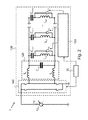
- Fig. 1 shows a schematic diagram of a power charger according to an exemplary embodiment of the present invention.
- a wireless power charger 1 may comprise a voltage source 10, a control module 20, and a power conversion module 100.
- the voltage source 10 is configured to provide an input voltage U IN .
- the power conversion module 100 may comprise a primary coil L p1 , L p2 , ..., L pN and a power switch S w1 , S w2 , ..., S wN .
- the primary coil L p1 , L p2 , ..., L pN is configured to convert electrical energy into magnetic energy.
- the control module 20 may be configured to control the multiplexer 160 and/or the power inverter circuit 140.
- the provided magnetic energy can then reconverted by a secondary coil of an energy harvesting device, not shown in Fig. 1 .
- the power switch S w1 , S w2 , ..., S wN is coupled to the primary coil L p1 , L p2 , ..., L pN in parallel and is configured to activate the primary coil L p1 , L p2 , ..., L pN by an open switch state and to deactivate the primary coil L p1 , L p2 , ..., L pN by a closed switch state.
- the power conversion module 100 comprises a multiplexer 160 which is configured to control the power switches S w1 , S w2 , ..., S wN and which is configured to serve as a selection circuit for selecting a primary coil L p1 , L p2 , ..., L pN for wireless energy transmission.
- the power conversion module 100 comprises an array of primary coils L p1 , L p2 , ..., L pN , the array comprising the primary coil L p1 , L p2 , ..., L pN and the at least one further primary coil L p1 , L p2 , ..., L pN .
- Fig. 1 three primary coils L p1 , L p2 , L p3 are shown.
- the power conversion module 100 comprises an EMC-filter circuit 120 comprising a capacitor C par and at least one inductor L 1 , L 2 .
- the EMC-filter circuit 120 comprises two inductors L 1 , L 2
- the power conversion module 100 comprises a filter capacitor C ser1 , C ser2 , ..., C serN which is coupled in series to the primary coil L p1 , L p2 , ..., L pN or in series to the at least one further primary coil L p1 , L p2 , ..., , L pN and which is assigned to the power switch S w1 , S w2 , ..., S wN or to the least one further power switch S w2 , ..., S wN and which is coupled in parallel to the capacitor C par of the EMC-filter circuit 120 if the power switch S w1 , S w2 , ..., S wN assigned to the filter capacitor C ser1 , C ser2 , ..., C serN is in closed switch state.
- the power conversion module 100 comprises a power inverter circuit 140, which is configured to convert an input voltage U IN into a supply voltage D OUT .
- the inductors L 1 , L 2 of the EMC-filter circuit 120 may for instance have an inductance between 0,1 and 500 pH or preferably between 0,5 and 3 ⁇ H, or most preferably for instance 1 ⁇ H.
- the primary coils L p1 , L p2 , L p3 may for instance have an inductance between 0,5 and 1500 ⁇ H, preferably between 1 and 50 ⁇ H, or most preferably for instance 24 ⁇ H.
- the filter capacitors C ser1 , C ser2 , C ser3 may for instance have a capacitance between 2 and 2500 nF, or preferably between 50 and 500 nF, or most preferably for instance 100 nF.
- the capacitor C par of the EMC-filter circuit 120 may for instance have a capacitance between 5 nF and 2500 nF, preferably between 50 nF and 500 nF, or most preferably for instance 200 nF.
- the required capacitance for the EMC filter is 400 nF, i.e. 2*100 nF from the bypassed filter capacitors C ser2 , C ser3 and 200 nF from the capacitor C par of the EMC-filter circuit 120.
- Typical values for the input voltage U IN may range from 1 to 10 V DC depending of the required transmitted power.
- Fig. 2 shows a schematic diagram of a wireless power charger according to an exemplary embodiment of the present invention.
- the power conversion module 100 comprises N primary coils L p1 , L p2 , ..., L pN , and N power switches S w1 , S w2 , ..., S wN in contrast to the setup with three primary coils and with three power switches as shown in Fig. 1 .
- Fig. 3 shows a schematic diagram of a wireless power charger for explaining the present invention.
- the wireless power charger as shown in Fig. 3 comprises a multiplexer with electronic power switches connected in series with each primary coil.
- Fig. 4 shows a schematic diagram of a flow-chart diagram of a method for operating a power conversion module according to an exemplary embodiment of the present invention.
- the method for operating a power conversion module 100 comprises the following steps of:
- activating S1 a primary coil L p1 , L p2 , ..., L pN by an open switch state of a power switch S w1 , S w2 , ..., S wN which is coupled to the primary coil L p1 , L p2 , ..., L pN in parallel may be performed.
- deactivating S2 the primary coil L p1 , L p2 , ..., L pN by a closed switch state of the power switch S w1 , S w2 , ..., S wN may be performed.
- the present disclosure also supports a computer program product including computer executable code or computer executable instructions that, when executed, causes at least one computer to execute the performing and computing steps described herein.
- a computer program may be stored or distributed on a suitable medium, such as an optical storage medium or a solid-state medium supplied together with or as part of other hardware, but may also be distributed in other forms, such as via the Internet or other wired or wireless telecommunication systems.
- a suitable medium such as an optical storage medium or a solid-state medium supplied together with or as part of other hardware, but may also be distributed in other forms, such as via the Internet or other wired or wireless telecommunication systems.
Landscapes
- Engineering & Computer Science (AREA)
- Power Engineering (AREA)
- Transportation (AREA)
- Mechanical Engineering (AREA)
- Computer Networks & Wireless Communication (AREA)
- Charge And Discharge Circuits For Batteries Or The Like (AREA)
Abstract
Description
- The present invention relates to the field of inductive charging or wireless charging. In particular, the present invention relates to a power conversion module for inductive charging for vehicles, a wireless power charger, and a method for operating a power conversion module.
- Multi-coil solutions for wireless power charger or wireless power transmitter comprise a power conversion unit and a control and communication. The power conversion unit may comprise a set of primary coils, a multiplexer for the primary coils, a power inverter, and a current sense circuit.
- Conventional multiplexers comprise an electronic switch connected in series with each primary coil coupled to the multiplexer.
- By activating a specific switch assigned to the primary coil it can be chosen which primary coil will be energized by the power inverter.
- For automotive versions of a wireless power charger, only one primary coil, which may comprise the best coupling factor with the secondary coil or receiving coil, is energized by the power converter. The other remaining primary coils will remain disconnected from the circuit.
- There may a need to improve inductive charging or wireless charging devices. These needs are met by the subject-matter of the independent claims. Further exemplary embodiments are evident from the dependent claims and the following description.
- An aspect of the present invention relates to a power conversion module for inductive charging for vehicles, the power conversion module comprising: a primary coil, which is configured to convert electrical energy into magnetic energy; and a power switch, which is coupled to the primary coil in parallel and which is configured to activate the primary coil by an open switch state and to deactivate the primary coil by a closed switch state.
- In other words, the present invention advantageously provides to replace the series circuit configuration of the (power) switches regarding the primary coils with a parallel circuit configuration of the (power) switches and the primary coils.
- In other words, the power switches are connected in parallel to the primary coils. In this configuration, each primary coil will have a parallel connection to one power switch assigned to the primary coil and used for de-activating and activating the primary coil.
- In particular, the power switch will be in short circuit for each primary coil which shall not be energized by the power inverter. Only the power switch corresponding to a primary coil which has to be energized will be left open and the other primary coils will be short circuit by the assigned or corresponding power switches.
- The present invention advantageously provides a better quality factor of the resonance circuit since no power switch or other elements with a specific conduction resistance are placed in series with the primary coil.
- The present invention further improves the efficiency of the energy transfer. The present invention further advantageously provides an improved foreign object detection mechanism, as the quality factor of the coupling of primary and secondary coils is improved, thereby allowing an improved detection and/or localization of the secondary coil of the device to be charged.
- The present invention can be advantageously applied to all wireless power chargers that use primary coils and a multiplexer circuit.
- According to a further, second aspect of the present invention, a wireless power charger is provided, the wireless power charger comprising a voltage source which is configured to provide an input voltage, a control module, and a power conversion module according to the first aspect of the present invention or according to any implementation form of the first aspect of the present invention.
- According to a further, third aspect of the present invention, a method for operating a power conversion module is provided, the method comprising the steps of activating a primary coil by an open switch state of a power switch, which is coupled to the primary coil in parallel; and deactivating the primary coil by a closed switch state of the power switch.
- According to an exemplary embodiment of the present invention, the power conversion module comprises at least one further primary coil, which is configured to convert electrical energy into magnetic energy and at least one further power switch, which is coupled to the further primary coil in parallel and which is configured to activate the further primary coil by an open switch state and to deactivate the further primary coil by a closed switch state. This advantageously provides a reliable selection of the primary coil to be used to transfer energy to a secondary coil, choosing a primary coil which has the best coupling factor with the secondary coil.
- According to an exemplary embodiment of the present invention, the power conversion module comprises a multiplexer which is configured to control the power switch and to control the at least one further power switch and which is configured to serve as a selection circuit for selecting the primary coil and/or the at least one further primary coil for wireless energy transmission. This advantageously allows improving the efficiency of the inductive coupling of an electrical device to the power conversion module for energy transfer. In other words, the primary coils are used for inductive charging or wireless charging.
- According to an exemplary embodiment of the present invention, the power conversion module comprises an array of primary coils, the array comprising the primary coil and the at least one further primary coil. The array may be a 2x1 array comprising two or more primary coils.
- The array may be formed to cover an area with primary coils. This advantageously allows covering an increased area for inductive charging, using the magnetic or electromagnetic field of the primary coil to transfer energy to a secondary coil of a device to be charged.
- According to an exemplary embodiment of the present invention, the power conversion module comprises an EMC-filter circuit comprising a filter capacitor and at least one inductor. EMC is the abbreviation for electromagnetic compatibility. The EMC-filter may be configured to reduce electromagnetic interference. The EMC-filter may improve the correct operation of the device or of the wireless power charger.
- Thereby, unwanted electromagnetic emission of the device or of the wireless power charger may be reduced. Further electromagnetic disturbances may be reduced.
- According to an exemplary embodiment of the present invention, the power conversion module comprises a filter capacitor, which is coupled in series to the primary coil or in series to the at least one further primary coil and which is assigned to the power switch or to the least one further power switch and which is coupled in parallel to the capacitor of the EMC-filter circuit if the power switch assigned to the filter capacitor is in closed switch state.
- This advantageously allows reducing the needed or necessary capacitance values of the capacitors of the power conversion module, as deactivated or non-operating primary coils are bypassed and by this bypassing, the assigned filter capacitors are connected in parallel to the capacitor of the EMC-filter circuit thereby reducing the necessary capacitance values of the capacitors.
- This advantageously allows providing a cost reduction of the power conversion module.
- According to an exemplary embodiment of the present invention, the power conversion module comprises a power inverter circuit, which is configured to convert a DC input voltage into an AC supply voltage.
- According to an exemplary embodiment of the present invention, the power switch and/or the least one further power switch is a metal-oxide-semiconductor field-effect transistor.
- According to an exemplary embodiment of the present invention, the metal-oxide-semiconductor field-effect transistor is a depletion-mode metal-oxide-semiconductor field-effect transistor.
- These and other aspects of the present invention will become apparent from and will be elucidated with reference to the embodiments described hereinafter.
- Exemplary embodiments of the present invention will be described in the following with reference to the following drawings: A more complete appreciation of the present invention and the intended advantages thereof will be more clearly understood by reference to the following schematic drawings, which are not to scale, wherein:
- Fig. 1
- shows a schematic diagram of a wireless power charger according to an exemplary embodiment of the present invention;
- Fig. 2
- shows a schematic diagram of a wireless power charger according to an exemplary embodiment of the present invention;
- Fig. 3
- shows a schematic diagram of a wireless power charger for explaining the present invention; and
- Fig. 4
- shows a schematic diagram of a flow-chart diagram of a method for operating a power conversion module according to an exemplary embodiment of the present invention.
- The illustration in the drawings is purely schematic and does not intend to provide scaling relations or size information. In different drawings or figures, similar or identical elements are provided with the same reference numerals.
- Generally, identical parts, units, entities or steps are provided with the same reference symbols in the description.
-
Fig. 1 shows a schematic diagram of a power charger according to an exemplary embodiment of the present invention. - A wireless power charger 1 may comprise a
voltage source 10, acontrol module 20, and apower conversion module 100. Thevoltage source 10 is configured to provide an input voltage UIN. Thepower conversion module 100 may comprise a primary coil Lp1, Lp2, ..., LpN and a power switch Sw1, Sw2, ..., SwN. The primary coil Lp1, Lp2, ..., LpN is configured to convert electrical energy into magnetic energy. - The
control module 20 may be configured to control themultiplexer 160 and/or thepower inverter circuit 140. - The provided magnetic energy can then reconverted by a secondary coil of an energy harvesting device, not shown in
Fig. 1 . - According to an exemplary embodiment of the present invention, the power switch Sw1, Sw2, ..., SwN is coupled to the primary coil Lp1, Lp2, ..., LpN in parallel and is configured to activate the primary coil Lp1, Lp2, ..., LpN by an open switch state and to deactivate the primary coil Lp1, Lp2, ..., LpN by a closed switch state.
- According to an exemplary embodiment of the present invention, the
power conversion module 100 comprises amultiplexer 160 which is configured to control the power switches Sw1, Sw2, ..., SwN and which is configured to serve as a selection circuit for selecting a primary coil Lp1, Lp2, ..., LpN for wireless energy transmission. - According to an exemplary embodiment of the present invention, the
power conversion module 100 comprises an array of primary coils Lp1, Lp2, ..., LpN, the array comprising the primary coil Lp1, Lp2, ..., LpN and the at least one further primary coil Lp1, Lp2, ..., LpN. InFig. 1 , three primary coils Lp1, Lp2, Lp3 are shown. - According to an exemplary embodiment of the present invention, the
power conversion module 100 comprises an EMC-filter circuit 120 comprising a capacitor Cpar and at least one inductor L1, L2. InFig. 1 , the EMC-filter circuit 120 comprises two inductors L1, L2 - According to an exemplary embodiment of the present invention, the
power conversion module 100 comprises a filter capacitor Cser1, Cser2, ..., CserN which is coupled in series to the primary coil Lp1, Lp2, ..., LpN or in series to the at least one further primary coil Lp1, Lp2, ..., , LpN and which is assigned to the power switch Sw1, Sw2, ..., SwN or to the least one further power switch Sw2, ..., SwN and which is coupled in parallel to the capacitor Cpar of the EMC-filter circuit 120 if the power switch Sw1, Sw2, ..., SwN assigned to the filter capacitor Cser1, Cser2, ..., CserN is in closed switch state. - According to an exemplary embodiment of the present invention, the
power conversion module 100 comprises apower inverter circuit 140, which is configured to convert an input voltage UIN into a supply voltage DOUT. - The inductors L1, L2 of the EMC-
filter circuit 120 may for instance have an inductance between 0,1 and 500 pH or preferably between 0,5 and 3 µH, or most preferably for instance 1 µH. - The primary coils Lp1, Lp2, Lp3 may for instance have an inductance between 0,5 and 1500 µH, preferably between 1 and 50 µH, or most preferably for instance 24 µH.
- The filter capacitors Cser1, Cser2, Cser3 may for instance have a capacitance between 2 and 2500 nF, or preferably between 50 and 500 nF, or most preferably for
instance 100 nF. - The capacitor Cpar of the EMC-
filter circuit 120 may for instance have a capacitance between 5 nF and 2500 nF, preferably between 50 nF and 500 nF, or most preferably for instance 200 nF. - In this example, the required capacitance for the EMC filter is 400 nF, i.e. 2*100 nF from the bypassed filter capacitors Cser2, Cser3 and 200 nF from the capacitor Cpar of the EMC-
filter circuit 120. - Typical values for the input voltage UIN may range from 1 to 10 V DC depending of the required transmitted power.
-
Fig. 2 shows a schematic diagram of a wireless power charger according to an exemplary embodiment of the present invention. - In
Fig. 2 , thepower conversion module 100 comprises N primary coils Lp1, Lp2, ..., LpN, and N power switches Sw1, Sw2, ..., SwN in contrast to the setup with three primary coils and with three power switches as shown inFig. 1 . - The further reference signs as shown in
Fig. 2 are already described in the description ofFig. 1 and are therefore not discussed any further. -
Fig. 3 shows a schematic diagram of a wireless power charger for explaining the present invention. - The wireless power charger as shown in
Fig. 3 comprises a multiplexer with electronic power switches connected in series with each primary coil. -
Fig. 4 shows a schematic diagram of a flow-chart diagram of a method for operating a power conversion module according to an exemplary embodiment of the present invention. - The method for operating a
power conversion module 100 comprises the following steps of: - As a first step of the method, activating S1 a primary coil Lp1, Lp2, ..., LpN by an open switch state of a power switch Sw1, Sw2, ..., SwN which is coupled to the primary coil Lp1, Lp2, ..., LpN in parallel may be performed.
- As a second step of the method, deactivating S2 the primary coil Lp1, Lp2, ..., LpN by a closed switch state of the power switch Sw1, Sw2, ..., SwN may be performed.
- From the foregoing, it will be apparent to those skilled in the art that a variety of methods, systems, computer programs on recording media, and the like, are provided.
- The present disclosure also supports a computer program product including computer executable code or computer executable instructions that, when executed, causes at least one computer to execute the performing and computing steps described herein.
- Many alternatives, modifications, and variations will be apparent to those skilled in the art in light of the above teachings. Of course, those skilled in the art readily recognize that there are numerous applications of the invention beyond those described herein.
- While the present invention has been described with reference to one or more particular embodiments, those skilled in the art recognize that many changes may be made thereto without departing from the scope of the present invention.
- It is therefore to be understood that within the scope of the appended claims and their equivalents, the inventions may be practiced otherwise than as specifically described herein.
- In the claims, the word "comprising" does not exclude other elements or steps, and the indefinite article "a" or "an" does not exclude a plurality. A single processor or other unit may fulfill the functions of several items recited in the claims.
- The mere fact that certain measures are recited in mutually different dependent claims does not indicate that a combination of these measured cannot be used to advantage.
- A computer program may be stored or distributed on a suitable medium, such as an optical storage medium or a solid-state medium supplied together with or as part of other hardware, but may also be distributed in other forms, such as via the Internet or other wired or wireless telecommunication systems.
Claims (12)
- A power conversion module (100) for inductive charging for vehicles, the power conversion module (100) comprising:- a primary coil (Lp1; Lp2; ...; LpN), which is configured to convert electrical energy into magnetic energy; and- a power switch (Sw1; Sw2; ...; SwN), which is coupled to the primary coil (Lp1; Lp2; ...; LpN) in parallel and which is configured to activate the primary coil (Lp1; Lp2; ...; LpN) by an open switch state and to deactivate the primary coil (Lp1; Lp2; ...; LpN) by a closed switch state.
- Power conversion module (100) according to claim 1, wherein the power conversion module (100) comprises:- at least one further primary coil (Lp2, ..., LpN), which is configured to convert electrical energy into magnetic energy; and- at least one further power switch (Sw2, ..., SwN), which is coupled to the at least one further primary coil (Lp2, ..., , LpN) in parallel and which is configured to activate the at least one further primary coil (Lp2, ..., , LpN) by an open switch state and to deactivate the at least one further primary coil (Lp2, ..., LpN) by a closed switch state.
- Power conversion module (100) according to claim 2, wherein the power conversion module (100) comprises a multiplexer (160) which is configured to control the power switch (Sw1; Sw2; ...; SwN) and/or to control the at least one further power switch (Sw2, ..., SwN) and which is configured to serve as a selection circuit for selecting the primary coil (Lp1; Lp2; ...; LpN) and/or the at least one further primary coil (Lp2, ..., LpN) for wireless energy transmission.
- Power conversion module (100) according to claim 2 or claim 3,
wherein the power conversion module (100) comprises an array of primary coils (Lp1, Lp2, ..., LpN), the array comprising the primary coil (Lp1; Lp2; ...; LpN) and the at least one further primary coil (Lp2, ..., LpN). - Power conversion module (100) according to one of the preceding claims,
wherein the power conversion module (100) comprises a EMC-filter circuit (120) comprising a capacitor (Cpar) and at least one inductor (L1, L2). - Power conversion module (100) according to claim 5, wherein the power conversion module (100) comprises a filter capacitor (Cser1; Cser2; ...; CserN) which is coupled in series to the primary coil (Lp1; Lp2; ...; LpN) or in series to the at least one further primary coil (Lp2, ..., , LpN) and which is assigned to the power switch (Sw1; Sw2; ...; SwN) or to the least one further power switch (Sw2, ..., SwN) and which is coupled in parallel to the capacitor (Cpar) of the EMC-filter circuit (120) if the power switch (Sw1; Sw2; ...; SwN) or the least one further power switch (Sw2, ..., SwN) assigned to the filter capacitor (Cser1, Cser2, ..., CserN) is in closed switch state.
- Power conversion module (100) according to one of the preceding claims,
wherein the power conversion module (100) comprises a power inverter circuit (140), which is configured to convert an input voltage (UIN) into a supply voltage (UOUT). - Power conversion module (100) according to one of the preceding claims,
wherein the power switch (Sw1, Sw2, .... SwN) or the least one further power switch (Sw2, ..., SwN) is a metal-oxide-semiconductor field-effect transistor. - Power conversion module (100) according to claim 8, wherein the metal-oxide-semiconductor field-effect transistor is a depletion-mode metal-oxide-semiconductor field-effect transistor.
- A wireless power charger (1) comprising a voltage source (10) which is configured to provide an input voltage (UIN), a control module (20) and a power conversion module (100) according to one of the preceding claims.
- Method for operating a power conversion module (100), the method comprising the steps of:- Activating (S1) a primary coil (Lp1, Lp2, ..., LpN) by an open switch state of a power switch (Sw1, Sw2, ..., SwN), which is coupled to the primary coil (Lp1, Lp2, ..., LpN) in parallel; and- Deactivating (S2) the primary coil (Lp1, Lp2, ..., LpN) by a closed switch state of the power switch (Sw1, Sw2, ..., SwN).
- A computer program configured to operate a method according to the preceding claim 11 when executed on a computer.
Priority Applications (1)
| Application Number | Priority Date | Filing Date | Title |
|---|---|---|---|
| EP15465536.9A EP3139466A1 (en) | 2015-09-07 | 2015-09-07 | Power conversion module for inductive charging for vehicles and method for operating a power conversion module |
Applications Claiming Priority (1)
| Application Number | Priority Date | Filing Date | Title |
|---|---|---|---|
| EP15465536.9A EP3139466A1 (en) | 2015-09-07 | 2015-09-07 | Power conversion module for inductive charging for vehicles and method for operating a power conversion module |
Publications (1)
| Publication Number | Publication Date |
|---|---|
| EP3139466A1 true EP3139466A1 (en) | 2017-03-08 |
Family
ID=54288742
Family Applications (1)
| Application Number | Title | Priority Date | Filing Date |
|---|---|---|---|
| EP15465536.9A Withdrawn EP3139466A1 (en) | 2015-09-07 | 2015-09-07 | Power conversion module for inductive charging for vehicles and method for operating a power conversion module |
Country Status (1)
| Country | Link |
|---|---|
| EP (1) | EP3139466A1 (en) |
Cited By (4)
| Publication number | Priority date | Publication date | Assignee | Title |
|---|---|---|---|---|
| WO2021232838A1 (en) * | 2020-05-19 | 2021-11-25 | 华为技术有限公司 | Terminal device and control method therefor |
| CN115091978A (en) * | 2022-08-01 | 2022-09-23 | 哈尔滨理工大学 | High-power wireless transmission device and method for electric automobile |
| CN119489704A (en) * | 2025-01-20 | 2025-02-21 | 福州大学 | An integrated system of electric vehicle wireless charging system, AC wired charging system and DC wired charging system |
| EP4404420A4 (en) * | 2022-01-20 | 2025-07-23 | Honor Device Co Ltd | TRANSMISSION END FOR WIRELESS CHARGING, CHARGING BASE AND SYSTEM |
Citations (4)
| Publication number | Priority date | Publication date | Assignee | Title |
|---|---|---|---|---|
| US20100259217A1 (en) * | 2009-04-08 | 2010-10-14 | Access Business Group International Llc | Selectable coil array |
| US20120139358A1 (en) * | 2010-12-01 | 2012-06-07 | Triune Ip Llc | Multiple Coil Data Transmission System |
| US20130154384A1 (en) * | 2011-12-15 | 2013-06-20 | Koji Nakamura | Contactless power receiving device, vehicle, contactless power transmitting device, and contactless power supply system |
| EP2747245A1 (en) * | 2011-09-21 | 2014-06-25 | Toyota Jidosha Kabushiki Kaisha | Contactless power transmission device, contactless power receiving device and contactless power transceiver system |
-
2015
- 2015-09-07 EP EP15465536.9A patent/EP3139466A1/en not_active Withdrawn
Patent Citations (4)
| Publication number | Priority date | Publication date | Assignee | Title |
|---|---|---|---|---|
| US20100259217A1 (en) * | 2009-04-08 | 2010-10-14 | Access Business Group International Llc | Selectable coil array |
| US20120139358A1 (en) * | 2010-12-01 | 2012-06-07 | Triune Ip Llc | Multiple Coil Data Transmission System |
| EP2747245A1 (en) * | 2011-09-21 | 2014-06-25 | Toyota Jidosha Kabushiki Kaisha | Contactless power transmission device, contactless power receiving device and contactless power transceiver system |
| US20130154384A1 (en) * | 2011-12-15 | 2013-06-20 | Koji Nakamura | Contactless power receiving device, vehicle, contactless power transmitting device, and contactless power supply system |
Cited By (4)
| Publication number | Priority date | Publication date | Assignee | Title |
|---|---|---|---|---|
| WO2021232838A1 (en) * | 2020-05-19 | 2021-11-25 | 华为技术有限公司 | Terminal device and control method therefor |
| EP4404420A4 (en) * | 2022-01-20 | 2025-07-23 | Honor Device Co Ltd | TRANSMISSION END FOR WIRELESS CHARGING, CHARGING BASE AND SYSTEM |
| CN115091978A (en) * | 2022-08-01 | 2022-09-23 | 哈尔滨理工大学 | High-power wireless transmission device and method for electric automobile |
| CN119489704A (en) * | 2025-01-20 | 2025-02-21 | 福州大学 | An integrated system of electric vehicle wireless charging system, AC wired charging system and DC wired charging system |
Similar Documents
| Publication | Publication Date | Title |
|---|---|---|
| CN106663966B (en) | Multi-mode wireless power transmitter | |
| US10790675B2 (en) | Apparatus for transmitting power wirelessly | |
| US10714979B2 (en) | Wireless power receiving terminal and wireless charging system | |
| US9762084B2 (en) | Wireless charging system and method for controlling the same | |
| EP3139466A1 (en) | Power conversion module for inductive charging for vehicles and method for operating a power conversion module | |
| US10608471B2 (en) | Multimode wireless power receiver circuit | |
| CN104600767B (en) | Electronic device | |
| CN108370240B (en) | Class E2 amplifier | |
| US20140132077A1 (en) | Wireless power transmitter having low noise and high efficiency, and related methods | |
| CA2960419C (en) | Charging circuit and mobile terminal | |
| US11735957B2 (en) | Wireless power transfer | |
| EP3086440B1 (en) | Array coil system | |
| US20160100461A1 (en) | Induction heat cooking apparatus | |
| US10187930B2 (en) | Induction heat cooking apparatus | |
| CN108233507A (en) | A kind of wireless charging circuit, system, method and electronic equipment | |
| US10667332B2 (en) | Induction heat cooking apparatus | |
| US10862340B2 (en) | Wireless power transmission apparatus and wireless power transmission method thereof | |
| CN105191102B (en) | Switched mode driving circuitry | |
| JP6237506B2 (en) | Power converter | |
| KR20160086342A (en) | Rectifying circuit for high-frequency power supply | |
| Wang et al. | A pulse energy injection inverter for the switch-mode inductive power transfer system | |
| US10491028B2 (en) | Wireless power transfer with generalized harmonic current | |
| US12614991B2 (en) | Bridge inverters for wireless charging | |
| CN222169635U (en) | Trigger circuit and inverter parallel system | |
| US12308660B2 (en) | Wireless power receiver, and method performed by wireless power receiver |
Legal Events
| Date | Code | Title | Description |
|---|---|---|---|
| PUAI | Public reference made under article 153(3) epc to a published international application that has entered the european phase |
Free format text: ORIGINAL CODE: 0009012 |
|
| STAA | Information on the status of an ep patent application or granted ep patent |
Free format text: STATUS: THE APPLICATION HAS BEEN PUBLISHED |
|
| AK | Designated contracting states |
Kind code of ref document: A1 Designated state(s): AL AT BE BG CH CY CZ DE DK EE ES FI FR GB GR HR HU IE IS IT LI LT LU LV MC MK MT NL NO PL PT RO RS SE SI SK SM TR |
|
| AX | Request for extension of the european patent |
Extension state: BA ME |
|
| STAA | Information on the status of an ep patent application or granted ep patent |
Free format text: STATUS: REQUEST FOR EXAMINATION WAS MADE |
|
| 17P | Request for examination filed |
Effective date: 20170908 |
|
| RBV | Designated contracting states (corrected) |
Designated state(s): AL AT BE BG CH CY CZ DE DK EE ES FI FR GB GR HR HU IE IS IT LI LT LU LV MC MK MT NL NO PL PT RO RS SE SI SK SM TR |
|
| STAA | Information on the status of an ep patent application or granted ep patent |
Free format text: STATUS: EXAMINATION IS IN PROGRESS |
|
| 17Q | First examination report despatched |
Effective date: 20190806 |
|
| RAP1 | Party data changed (applicant data changed or rights of an application transferred) |
Owner name: CONTINENTAL AUTOMOTIVE GMBH |
|
| STAA | Information on the status of an ep patent application or granted ep patent |
Free format text: STATUS: THE APPLICATION IS DEEMED TO BE WITHDRAWN |
|
| 18D | Application deemed to be withdrawn |
Effective date: 20210401 |