EP3139306A1 - Biometric authentication device, biometric authentication method and biometric authentication program - Google Patents
Biometric authentication device, biometric authentication method and biometric authentication program Download PDFInfo
- Publication number
- EP3139306A1 EP3139306A1 EP16186293.3A EP16186293A EP3139306A1 EP 3139306 A1 EP3139306 A1 EP 3139306A1 EP 16186293 A EP16186293 A EP 16186293A EP 3139306 A1 EP3139306 A1 EP 3139306A1
- Authority
- EP
- European Patent Office
- Prior art keywords
- biometric
- image
- model
- storage
- similarities
- Prior art date
- Legal status (The legal status is an assumption and is not a legal conclusion. Google has not performed a legal analysis and makes no representation as to the accuracy of the status listed.)
- Granted
Links
Images



Classifications
-
- G—PHYSICS
- G06—COMPUTING OR CALCULATING; COUNTING
- G06V—IMAGE OR VIDEO RECOGNITION OR UNDERSTANDING
- G06V40/00—Recognition of biometric, human-related or animal-related patterns in image or video data
- G06V40/10—Human or animal bodies, e.g. vehicle occupants or pedestrians; Body parts, e.g. hands
- G06V40/12—Fingerprints or palmprints
- G06V40/1347—Preprocessing; Feature extraction
-
- G—PHYSICS
- G06—COMPUTING OR CALCULATING; COUNTING
- G06F—ELECTRIC DIGITAL DATA PROCESSING
- G06F18/00—Pattern recognition
- G06F18/20—Analysing
- G06F18/22—Matching criteria, e.g. proximity measures
-
- G—PHYSICS
- G06—COMPUTING OR CALCULATING; COUNTING
- G06T—IMAGE DATA PROCESSING OR GENERATION, IN GENERAL
- G06T7/00—Image analysis
- G06T7/70—Determining position or orientation of objects or cameras
- G06T7/73—Determining position or orientation of objects or cameras using feature-based methods
- G06T7/74—Determining position or orientation of objects or cameras using feature-based methods involving reference images or patches
-
- G—PHYSICS
- G06—COMPUTING OR CALCULATING; COUNTING
- G06V—IMAGE OR VIDEO RECOGNITION OR UNDERSTANDING
- G06V40/00—Recognition of biometric, human-related or animal-related patterns in image or video data
- G06V40/10—Human or animal bodies, e.g. vehicle occupants or pedestrians; Body parts, e.g. hands
- G06V40/107—Static hand or arm
- G06V40/11—Hand-related biometrics; Hand pose recognition
-
- G—PHYSICS
- G06—COMPUTING OR CALCULATING; COUNTING
- G06V—IMAGE OR VIDEO RECOGNITION OR UNDERSTANDING
- G06V40/00—Recognition of biometric, human-related or animal-related patterns in image or video data
- G06V40/10—Human or animal bodies, e.g. vehicle occupants or pedestrians; Body parts, e.g. hands
- G06V40/107—Static hand or arm
- G06V40/113—Recognition of static hand signs
-
- G—PHYSICS
- G06—COMPUTING OR CALCULATING; COUNTING
- G06V—IMAGE OR VIDEO RECOGNITION OR UNDERSTANDING
- G06V40/00—Recognition of biometric, human-related or animal-related patterns in image or video data
- G06V40/10—Human or animal bodies, e.g. vehicle occupants or pedestrians; Body parts, e.g. hands
- G06V40/12—Fingerprints or palmprints
- G06V40/1365—Matching; Classification
-
- G—PHYSICS
- G06—COMPUTING OR CALCULATING; COUNTING
- G06F—ELECTRIC DIGITAL DATA PROCESSING
- G06F21/00—Security arrangements for protecting computers, components thereof, programs or data against unauthorised activity
- G06F21/30—Authentication, i.e. establishing the identity or authorisation of security principals
- G06F21/31—User authentication
- G06F21/32—User authentication using biometric data, e.g. fingerprints, iris scans or voiceprints
-
- G—PHYSICS
- G06—COMPUTING OR CALCULATING; COUNTING
- G06T—IMAGE DATA PROCESSING OR GENERATION, IN GENERAL
- G06T9/00—Image coding
- G06T9/001—Model-based coding, e.g. wire frame
-
- G—PHYSICS
- G06—COMPUTING OR CALCULATING; COUNTING
- G06V—IMAGE OR VIDEO RECOGNITION OR UNDERSTANDING
- G06V40/00—Recognition of biometric, human-related or animal-related patterns in image or video data
- G06V40/10—Human or animal bodies, e.g. vehicle occupants or pedestrians; Body parts, e.g. hands
- G06V40/14—Vascular patterns
Definitions
- a certain aspect of embodiments described herein relates to a biometric authentication device, a biometric authentication method and a biometric authentication program.
- a biometric authentication technology performing an individual authentication with use of a biometric feature such as a fingerprint image, a vein image or a face image is widely spread, as a method of identifying a person with high accuracy
- the biometric authentication technology can perform individual authentication with high accuracy.
- the present invention has been made in view of those circumstances, and an object thereof is to provide a biometric authentication device, a biometric authentication method and a biometric authentication program that are capable of performing authentication with high accuracy.
- a biometric authentication device performing an authentication based on a similarity between a biometric image that is an object of comparing and an enrolled biometric image, including: a storage configured to store a plurality of model images generated by changing a bending angle of a joint of a biometric model and correction information of each of the plurality of model images; a biometric sensor configured to capture a biometric image that is an object of comparing; a comparator configured to determine similarities between the biometric image captured by the biometric sensor and the plurality of model images; a selector configured to select a model image based on the similarities; a reader configured to read correction information corresponding to the model image that is selected, from the storage; and a corrector configured to correct one of the biometric image captured by the biometric sensor or the enrolled biometric image based on the correction information.
- a biometric feature obtained at the time is compared with a biometric feature that is enrolled in advance.
- the biometric feature changes according to the bending angle. Therefore, the shape during the enrolling process may be different from the shape during the authentication process. In this case, the comparing may be wrongly performed.
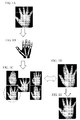
- FIG. 1A to FIG. 1E schematically illustrate processes performed by a biometric authentication device in accordance with a first embodiment.
- a palm is used as an example of a biometric instance.
- a standard biometric shape is generated by capturing images of palms of many people and averaging the images of the palms.
- FIG. 1B a three-dimensional model data is generated in advance for the purpose of simulating a shape of a palm, with use of the biometric shape of FIG. 1A .
- FIG. 1C two-dimensional simulation images are generated from the three-dimensional model data by variously changing angles of joints of fingers for deforming the three-dimensional model data.
- FIG. 1D illustrates a palm image of a user captured by a biometric sensor.
- a position of each two-dimensional simulation image of FIG. 1C is roughly adjusted to the palm image of FIG. 1D .
- positions, angles, sizes and average brightness values are roughly adjusted.
- contrasting densities of the images are compared, and similarities of the contrasting densities are calculated.
- a two-dimensional simulation image of which contrasting density similarity is the highest is selected. In the example of FIG. 1C , a left lower two-dimensional simulation image is selected.
- joint angles of fingers used for the generation of the selected two-dimensional simulation image are obtained.
- the angles of the joints of the fingers are applied to the palm image of FIG. 1D .
- FIG. 1E it is possible to correct the captured image so that the joint angles of the fingers of the palm image are consistent with joint angles of the fingers during making an enrolled data.
- the processes it is possible to adjust joint angles of fingers of a palm image obtained during an authentication process to joint angles of the fingers obtained during making an enrolled data. Therefore, the authentication accuracy can be improved.
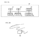
- FIG. 2A illustrates a block diagram for describing a hardware structure of a biometric authentication device 100 in accordance with the first embodiment.
- FIG. 2B illustrates a schematic view of a biometric sensor 105 described later.
- the biometric authentication device 100 has a CPU 101, a RAM (Random Access Memory) 102, a memory device 103, a display device 104, the biometric sensor 105, an attribute information obtainer 106 and so on. These components are coupled to each other with a bus or the like.
- RAM Random Access Memory
- the CPU 101 is a central processing unit.
- the CPU 101 includes one or more core.
- the RAM102 is a volatile memory temporally storing a program executed by the CPU 101, a data processed by the CPU 101, and so on.
- the memory device 103 is a nonvolatile memory device.
- the memory device 103 may be a SSD (Solid State Drive) such as a ROM (Read Only Memory) or a flash memory, or a hard disk driven by a hard disk drive.
- the memory device 103 stores a biometric authentication program.
- the display device 104 is a liquid crystal display, an electro luminescence panel or the like and displays a result of a process of the biometric authentication device 100.
- the biometric sensor 105 is a sensor to obtain a biometric image of a user.
- the biometric sensor 105 may be a non-contact type sensor that obtains a biometric image without contacting.
- the biometric sensor 105 is a sensor to obtain a palm image without contacting and is, for example, a CMOS (Complementary Metal Oxide Semiconductor) camera or the like.
- the biometric sensor 105 captures a palm image including a vein pattern with use of a near-infrared light.
- the attribute information obtainer 106 is an inputting component such as a keyboard, a mouse and so on.
- the attribute information obtainer 106 is a device for inputting an ID or the like for identifying a user.
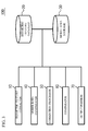
- FIG. 3 illustrates a functional block of the biometric authentication device 100.
- the biometric authentication device 100 acts as a biometric feature extractor 10, a biometric feature database 20, a model data storage 30, a model data comparator 40, a correction processor 50, a comparator 60 and an output portion 70.
- FIG. 4 illustrates a flowchart of an example of an enrollment process.
- the attribute information obtainer 106 obtains attribute information of a user.
- the biometric feature extractor 10 obtains a palm image of the user from the biometric sensor 105 as an enrollment biometric image (Step S1).
- a joint angle of each finger of the palm of the user becomes a predetermined value.
- the joint angle of each finger in this case is hereinafter referred to as a reference joint angle.
- the biometric feature extractor 10 extracts a vein pattern from the enrolled biometric image as a biometric feature (Step S2).
- the biometric feature database 20 relates the attribute information obtained by the attribute information obtainer 106 with a biometric feature extracted by the biometric feature extractor 10 and stores the attribute information and the biometric feature (Step S3). With the processes, an enrolled biometric image of each user can be enrolled.
- FIG. 5 illustrates each function of the model data storage 30.
- the model data storage 30 acts as a storage 31 to store changeable angle information of joint and a storage 32 to store three dimensional model data.
- the storage 31 to store changeable angle information of joint stores changeable angle information of joint.
- the changeable angle information of joint is information expressing movement of each joint of a biometric instance that is a comparing object.
- the changeable angle information of joint is 0 degree to 90 degrees or the like.
- the storage 32 to store three dimensional model data stores a three dimensional model data.
- the three dimensional model data is a model data in which a biometric instance is expressed by three dimensions.
- the changeable angle information of joint and the three dimensional model data can be extracted as a value data from abstract shape models of a biometric instance of a standard human that is extracted from many humans in advance.
- the storage 32 to store three dimensional model data stores a three dimensional model data for simulating a shape of a palm.
- This operation corresponds to an operation that is generally called "modeling" in the art of three dimensional CG technology.
- the operation is an operation in which a user for generating a data refers to a standard biometric shape model, digitalizes information such as arrangements of joints forming a biometric instance, an aspect of a skin, deformation of the skin according to bending of the joints or the like, and generates a single three-dimensional model data of the biometric shape.
- a tool for the operation is called a three-dimensional modeler. There are various tools.
- any method can be used as a method of making the shape of the biometric instance utilizable as a three-dimensional model data.
- any method can be used.
- FIG. 6 illustrates details of each function of the biometric authentication device 100.
- the model data comparator 40 acts as a joint angle generator 41, a rendering portion 42, a two-dimensional image storage 43, a comparator 44 and a captured image storage 45.
- the correction processer 50 acts as an inverse reference portion 51, a joint angle storage 52, a corrector 53, a reference joint angle storage 54 and a corrected image storage 55.
- the joint angle generator 41 gets changeable angle information of joint from the storage 31 to store changeable angle information of joint and generates combination information of joint angles in which each joint angle is slightly changed based on a step angle determined in advance. For example, all joint angles in a case where each joint angle is slightly changed are generated as a combination of a first to N-th.
- FIG. 7 illustrates a table of each generated combination information.
- an identical value may be used for all joints as a step angle.
- the step angle may be changed with respect to at least two joints, because movements of joints are slightly different from each other and deformations of skins of a biometric instance during movement of each joint are different from each other.
- a skin of a palm is greatly pulled and greatly moves in accordance with the movement of the thumb.
- an influence of other fingers other than the thumb is smaller than the influence of the thumb. For example, when the thumb moves by five degrees, a large area of the skin of the palm greatly moves.
- the step angle is small and the angle changing can be finely set, because the importance of the thumb is large. It is possible to achieve efficiency by reducing the number of combinations of joint angles when the step angle is large and the angle is changed roughly.
- the rendering portion 42 generates a two-dimensional simulation image of a biometric instance with use of a three-dimensional CG technology based on the three-dimensional model data stored in the storage 32 to store three-dimensional model data.
- the rendering portion 42 generates a two simulation images under a condition that a skin of the three-dimensional model data is deformed, with respect to each combination of joint angles generated by the joint angle generator 41.
- the operation for generating two-dimensional simulation images based on deformations of a three-dimensional model data and joints of the model data is called a three-dimensional image rendering.
- the two-dimensional image storage 43 stores the two-dimensional simulation images generated by the rendering portion 42 together with a combination of joint angles used during the generation of each two-dimensional simulation image.
- FIG. 8A illustrates an example of a three-dimensional model data.
- FIG. 8B illustrates an example of two-dimensional simulation images of combinations of joint angles, that are generated by the rendering portion 42.
- the comparator 44 compares the two-dimensional simulation images stored by the two-dimensional image storage 43 with a palm image captured by the biometric sensor 105 during the authentication process.
- the palm image can be obtained by the captured image storage 45 that temporarily stores the palm image captured by the biometric sensor 105.
- FIG. 8C illustrates an example of the palm image.
- An object with which the comparator 44 compares is not a biometric feature data that is used for an individual authentication and identifying a person but information for comparing a difference between shape of biometric instances.
- contrasting density information can be used.
- Outline information shape of palm
- a comparing can be performed with a simple process.
- the contrasting density information is used as an example.
- the comparator 44 roughly adjusts a position of the palm image to a position of a biometric instance captured in the two-dimensional simulation images by a parallel movement, a rotation movement, an enlargement or reduction. After that, the comparator 44 calculates a similarity between parts of the biometric instances captured in the images based on the contrasting density, and digitalizes the similarity as a score. The comparator 44 repeats comparing between all two-dimensional simulation images generated with respect to each combination of joint angle and the palm image and selects one of the two-dimensional simulation images of which similarity of contrasting density is the highest.
- the inverse reference portion 51 obtains a combination of joint angles used during the generation of the two-dimensional simulation image selected by the comparator 44 from the two-dimensional image storage 43.
- the joint angle storage 52 stores the combination of joint angles obtained by the inverse reference portion 51.
- the corrector 53 obtains the palm image from the captured image storage 45, and corrects the palm image based on the combination of joint angles stored by the joint angle storage 52.
- the corrector 53 identifies the position of each joint of the pal image as well as the case where the position of the two-dimensional simulation image is adjusted.
- the corrector 53 obtains the reference joint angle from the reference joint angle storage 54.
- the corrector 53 corrects the palm image so that the joint angles obtained based on the position of each identified joint angle are consistent with the reference joint angles.
- the corrected palm image (hereinafter referred to as a corrected image) is stored by the corrected image storage 55.
- FIG. 8D illustrates an example of a corrected image.
- the biometric feature extractor 10 extracts a vein pattern from the corrected image as a biometric feature.
- the extracted biometric feature is stored by a biometric feature storage 11.
- FIG. 8E illustrates an extracted vein pattern.
- the comparator 60 compares the vein pattern stored in the biometric feature storage 11 with a biometric feature of each enrolled biometric image enrolled in the biometric feature database 20.
- FIG. 8F illustrates an example of an enrolled biometric feature.
- the comparator 60 calculates a similarity between the biometric feature stored by the biometric feature storage 11 and the biometric feature of the enrolled biometric image enrolled in the biometric feature database 20, and determines whether the similarity is equal to or more than a threshold. When the similarity is equal to or more than the threshold, the output portion 70 outputs information of success of the comparing.
- the similarities are ranked and the similarities may be subjected to the following processes in order of high similarities. For example, based on the two-dimensional simulation image of which similarity is the highest, when the comparing of the comparator 60 is failed, the processes may be performed based on the two-dimensional simulation image of which similarity is the second highest. In this manner, the process may be repeated in order of the similarities until the comparing of the biometric features is succeeded.
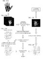
- FIG. 9 illustrates a flowchart of the above-mentioned processes.
- the joint angle generator 41 assigns 1 into a parameter i (Step S1).
- the joint angle generator 41 generates all joint angles of i-th combination (Step S2).
- the rendering portion 42 generates two-dimensional simulations images based on the all joint angles generated in Step S1 and stores the two-dimensional simulation images in the two-dimensional image storage 43 (Step S3).
- the comparator 44 calculates a similarity between the two-dimensional simulation images stored in the two-dimensional image storage 43 and a palm image captured by the biometric sensor 105 during the authentication process by the contrasting density comparing (Step S4).
- Step S5 the joint angle generator 41 adds 1 to the parameter i (Step S5).
- Step S6 the joint angle generator 41 determines whether the parameter i exceeds the number N of the combinations. When it is not determined that the parameter i exceeds N, Step S2 is executed again.
- the comparator 44 selects a two-dimensional simulation image of which similarity of contrasting density comparing is the highest.
- the inverse reference portion 51 inversely obtains a combination of joint angles used for the generation of the two-dimensional simulation image selected by the comparator 44 from the joint angle generator 41 and stores the combination of the joint angles in the joint angle storage 52 (Step S7).
- the corrector 53 obtains the palm image from the captured image storage 45 and corrects the palm image based on the combination of joint angles stored by the joint angle storage 52 (Step S8).
- the corrected image storage 55 stores the corrected image.
- the biometric feature extractor 10 extracts a vein pattern as a biometric feature from the corrected image (Step S9).
- the biometric feature storage 11 stores the extracted biometric feature.
- the comparator 60 compares the biometric feature stored by the biometric feature storage 11 with a biometric feature of an enrolled biometric image enrolled in the biometric feature database 20. When a similarity of the comparing is equal to or more than a threshold, the output portion 70 outputs information of success of the comparing (Step S10).
- the joint angles of the fingers of the palm image obtained during the authentication process can be adjusted to the joint angles of the fingers during obtaining the enrolled biometric feature image.
- the structure is not limited. For example, when the joint angles of the fingers of the palm image obtained during the authentication process get closer to the joint angles of the fingers during obtaining the enrolled biometric image, the authentication accuracy can be improved.
- the standard biometric shape model is used.
- joint information or three-dimensional information may be extracted from biometric shape of a user himself or herself and the information may be used as the three-dimensional model data.
- a description will be given of an example in which joint information or three-dimensional shape information extracted from a biometric shape of a user when enrolling an enrolled biometric image is used as a three-dimensional model data.
- FIG. 10 illustrates a block diagram for describing each function in a case where the reference joint angle storage 54, the storage 32 to store three dimensional model data and the storage 31 to store changeable angle information of joint store information.
- the storage 31 to store changeable angle information of joint stores a value data of the changeable angle information of joint extracted from the abstract shape model of a biometric body of a standard human obtained by sampling many humans in advance.
- a three-dimensional shape model extractor 81 extracts a three-dimensional model data for simulating a palm shape from a palm image captured by the biometric sensor 105 by a method such as the above-mentioned modeling. In this case, when a guide or the like is used, a joint angle of each finger of a palm of a user becomes a predetermined value.
- a storage 82 to store three-dimensional shape model makes the reference joint angle storage 54 store a joint angle of each finger. And, the storage 82 to store three-dimensional shape model makes the storage 32 to store three dimensional data store the three-dimensional model data.
- the changeable angle information of joint may also be extracted from a palm shape. Alternately, a user may input changeable joint angles as values. Storage place of the changeable angle information of joint, reference joint angles and the three-dimensional model is not limited when the changeable angle information, the reference joint angles and the three-dimensional model data are linked to the user.
- the changeable angle information, the reference joint angles and the three-dimensional model data may be separately stored from the biometric feature of the enrolled biometric image or stored in the biometric feature database 20.
- the comparing process is the same except for changing the three-dimensional model data that is used by the user. After the user is identified by inputting a user ID, it is possible to perform the comparing process with use of the three-dimensional model data of the user.
- the palm image is corrected so that joint angles of fingers of the palm image captured by the biometric sensor 105 during the authentication process are consistent to the reference joint angles.
- joint angles of fingers of the enrolled biometric image may be corrected.
- a description will be given of an example in which the joint angles of fingers of the enrolled biometric image are corrected.
- FIG. 11 illustrates details of each function of the biometric authentication device 100 in the embodiment. The same processes as the first embodiment are performed until the joint angle storage 52 stores the combinations of joint angles obtained by the inverse reference portion 51.
- FIG. 12A illustrates a three-dimensional model data.
- FIG. 12B illustrates a two-dimensional simulation image of every combination of the joint angles generated by the rendering portion 42.
- FIG 12C illustrates a palm image.
- the corrector 53 obtains a biometric feature of the enrolled biometric image from the biometric feature database 20. And the corrector 53 corrects the biometric feature based on the combinations of the joint angles stored by the joint angle storage 52.
- the biometric feature of the enrolled biometric image of comparing object can be identified.
- FIG. 12D illustrates the biometric feature of the identified enrolled biometric feature.
- the corrector 53 obtains the reference joint angles from the reference joint angle storage 54. Next, the corrector 53 corrects the biometric feature of the enrolled biometric image so that a difference between the reference joint angles and the joint angles stored by the joint angle storage 52 becomes zero.
- the corrected biometric feature is stored by the corrected image storage 55.
- FIG. 12E illustrates the corrected biometric feature.
- the biometric feature extractor 10 extracts a vein pattern as a biometric feature from the palm image stored by the captured image storage 45.
- FIG. 12F illustrates an example of an extracted biometric feature.
- the biometric feature storage 11 stores the extracted biometric feature.
- the comparator 60 compares the vein pattern stored by the biometric feature storage 11 with the corrected biometric feature. In concrete, the comparator 60 calculates a similarity between the biometric feature stored by the biometric feature storage 11 and the corrected biometric feature and determines whether the similarity is equal to or more than a threshold. When the similarity is equal to or more than the threshold, the output portion 70 outputs information of success of comparing.
- FIG. 13 illustrates a flowchart of the above-mentioned processes.
- Step S11 to Step S 17 are the same as Step S1 to Step S7 of FIG. 9 .
- the corrector 53 obtains the biometric feature of the enrolled biometric image from the biometric feature database 20 and corrects the biometric feature based on the combination of the joint angles stored by the joint angle storage 52 (Step S18).
- the corrected image storage 55 stores the corrected biometric feature.
- the biometric feature extractor 10 extracts a vein pattern as a biometric feature from the palm image stored by the captured image storage 45 (Step S 19).
- the biometric feature storage 11 stores the extracted biometric feature.
- the comparator 60 compares the biometric feature stored by the biometric feature storage 11 with the corrected biometric feature.
- the output portion 70 outputs information of success of comparing (Step S20).
- the joint angles of the fingers during obtaining the enrolled biometric image can be adjusted to the joint angles of the fingers of the palm image captured during the authentication process.
- the structure is not limited. For example, when the joint angles of the fingers during obtaining the enrolled biometric image get closer to the joint angles of the fingers of the palm image obtained during the authentication process, the authentication accuracy can be improved.
- the palm is used as the biometric instance.
- the biometric instance is not limited to a palm.
- a biometric instance in which a shape is changed according to a bending angle of a joint can be used as an object of the above-mentioned embodiments.
- a finger is used as a biometric instance, and a fingerprint or a finger vein can be used as a biometric instance.
- an enrolled biometric image that is an object of comparing is identified by inputting an ID or the like.
- the structure is not limited.
- a biometric feature extracted from a corrected image may be compared with a biometric feature of enrolled biometric images of all users.
- biometric features of enrolled biometric images of all users may be corrected, and each biometric feature may be compares with a biometric feature extracted from a palm image.
- the highest similarity is equal to or more than a threshold
- a user who is an object of comparing is consistent with a user of the enrolled biometric image.
- the comparing is succeeded.
- the storage 32 to store three-dimensional model data acts as a storage configured to store a plurality of model images generated by changing a bending angle of a joint of a biometric model and correction information of each of the plurality of model images.
- the combinations of joint angles related to each model image corresponds to an example of correction information of each model image.
- the biometric sensor 105 acts as a biometric sensor configured to capture a biometric image that is an object of comparing.
- the comparator 44 acts as a comparator configured to determine similarities between the biometric image captured by the biometric sensor and the plurality of model images.
- the comparator 44 also acts as a selector configured to select a model image based on the similarities.
- the inverse reference portion 51 acts as a reader configured to read correction information corresponding to the model image that is selected, from the storage.
- the corrector 53 acts as a corrector configured to correct one of the biometric image captured by the biometric sensor or the enrolled biometric image.
Landscapes
- Engineering & Computer Science (AREA)
- Theoretical Computer Science (AREA)
- Physics & Mathematics (AREA)
- General Physics & Mathematics (AREA)
- Human Computer Interaction (AREA)
- Multimedia (AREA)
- Computer Vision & Pattern Recognition (AREA)
- Data Mining & Analysis (AREA)
- Life Sciences & Earth Sciences (AREA)
- Artificial Intelligence (AREA)
- Bioinformatics & Cheminformatics (AREA)
- Bioinformatics & Computational Biology (AREA)
- Evolutionary Biology (AREA)
- Evolutionary Computation (AREA)
- General Engineering & Computer Science (AREA)
- Collating Specific Patterns (AREA)
- Measurement Of The Respiration, Hearing Ability, Form, And Blood Characteristics Of Living Organisms (AREA)
Abstract
Description
- A certain aspect of embodiments described herein relates to a biometric authentication device, a biometric authentication method and a biometric authentication program.
- A biometric authentication technology performing an individual authentication with use of a biometric feature such as a fingerprint image, a vein image or a face image is widely spread, as a method of identifying a person with high accuracy The biometric authentication technology can perform individual authentication with high accuracy.
- The present invention has been made in view of those circumstances, and an object thereof is to provide a biometric authentication device, a biometric authentication method and a biometric authentication program that are capable of performing authentication with high accuracy.
- According to an aspect of the present invention, there is provided a biometric authentication device performing an authentication based on a similarity between a biometric image that is an object of comparing and an enrolled biometric image, including: a storage configured to store a plurality of model images generated by changing a bending angle of a joint of a biometric model and correction information of each of the plurality of model images; a biometric sensor configured to capture a biometric image that is an object of comparing; a comparator configured to determine similarities between the biometric image captured by the biometric sensor and the plurality of model images; a selector configured to select a model image based on the similarities; a reader configured to read correction information corresponding to the model image that is selected, from the storage; and a corrector configured to correct one of the biometric image captured by the biometric sensor or the enrolled biometric image based on the correction information.
- The object and advantages of the invention will be realized and attained by means of the elements and combinations particularly pointed out in the claims. It is to be understood that both the foregoing general description and the following detailed description are exemplary and explanatory and are not restrictive of the invention, as claimed.
-
-
FIG. 1A to FIG. 1E schematically illustrate processes performed by a biometric authentication device in accordance with a first embodiment; -
FIG. 2A illustrates a block diagram for describing a hardware structure of a biometric authentication device in accordance with a first embodiment; -
FIG. 2B illustrates a schematic view of a biometric sensor; -
FIG. 3 illustrates a functional block of a biometric authentication device; -
FIG 4 illustrates a flowchart of an example of an enrollment process; -
FIG. 5 illustrates each function of a model data storage; -
FIG. 6 illustrates details of each function of a biometric authentication device; -
FIG. 7 illustrates a table of each generated combination information; -
FIG. 8A illustrates an example of a three-dimensional model data; -
FIG. 8B illustrates an example of two-dimensional simulation images of combinations of joint angles; -
FIG. 8C illustrates an example of a palm image; -
FIG. 8D illustrates an example of a corrected image; -
FIG. 8E illustrates an extracted vein pattern; -
FIG. 8F illustrates an example of an enrolled biometric feature; -
FIG 9 illustrates a flowchart of a first embodiment; -
FIG. 10 illustrates a block diagram of each function of a second embodiment; -
FIG. 11 illustrates details of each function of a biometric authentication device in a second embodiment; -
FIG 12A illustrates an example of a three-dimensional model data; -
FIG 12B illustrates an example of two-dimensional simulation images of combinations of joint angles; -
FIG. 12C illustrates an example of a palm image; -
FIG. 12D illustrates a biometric feature of an identified enrolled biometric feature; -
FIG. 12E illustrates a corrected biometric feature; -
FIG. 12F illustrates an example of an extracted biometric feature; -
FIG. 13 illustrates a flowchart of a second embodiment. - In an individual authentication with use of a biometric feature, in a case where the individual authentication is actually performed, a biometric feature obtained at the time is compared with a biometric feature that is enrolled in advance. When a shape of a biometric instance deforms in accordance with a bending angle of a joint, the biometric feature changes according to the bending angle. Therefore, the shape during the enrolling process may be different from the shape during the authentication process. In this case, the comparing may be wrongly performed.
-
FIG. 1A to FIG. 1E schematically illustrate processes performed by a biometric authentication device in accordance with a first embodiment. A palm is used as an example of a biometric instance. As illustrated inFIG. 1A , a standard biometric shape is generated by capturing images of palms of many people and averaging the images of the palms. Next, as illustrated inFIG. 1B , a three-dimensional model data is generated in advance for the purpose of simulating a shape of a palm, with use of the biometric shape ofFIG. 1A . Next, as illustrated inFIG. 1C , two-dimensional simulation images are generated from the three-dimensional model data by variously changing angles of joints of fingers for deforming the three-dimensional model data. -
FIG. 1D illustrates a palm image of a user captured by a biometric sensor. Next, a position of each two-dimensional simulation image ofFIG. 1C is roughly adjusted to the palm image ofFIG. 1D . Thus, positions, angles, sizes and average brightness values are roughly adjusted. After that, contrasting densities of the images are compared, and similarities of the contrasting densities are calculated. And, a two-dimensional simulation image of which contrasting density similarity is the highest is selected. In the example ofFIG. 1C , a left lower two-dimensional simulation image is selected. - Next, joint angles of fingers used for the generation of the selected two-dimensional simulation image are obtained. Next, the angles of the joints of the fingers are applied to the palm image of
FIG. 1D . Thus, as illustrated inFIG. 1E , it is possible to correct the captured image so that the joint angles of the fingers of the palm image are consistent with joint angles of the fingers during making an enrolled data. With the processes, it is possible to adjust joint angles of fingers of a palm image obtained during an authentication process to joint angles of the fingers obtained during making an enrolled data. Therefore, the authentication accuracy can be improved. - A description will be given of a concrete structure of a biometric authentication device in accordance with a first embodiment.
FIG. 2A illustrates a block diagram for describing a hardware structure of abiometric authentication device 100 in accordance with the first embodiment.FIG. 2B illustrates a schematic view of abiometric sensor 105 described later. As illustrated inFIG. 2A , thebiometric authentication device 100 has aCPU 101, a RAM (Random Access Memory) 102, amemory device 103, adisplay device 104, thebiometric sensor 105, anattribute information obtainer 106 and so on. These components are coupled to each other with a bus or the like. - The
CPU 101 is a central processing unit. TheCPU 101 includes one or more core. The RAM102 is a volatile memory temporally storing a program executed by theCPU 101, a data processed by theCPU 101, and so on. - The
memory device 103 is a nonvolatile memory device. Thememory device 103 may be a SSD (Solid State Drive) such as a ROM (Read Only Memory) or a flash memory, or a hard disk driven by a hard disk drive. Thememory device 103 stores a biometric authentication program. Thedisplay device 104 is a liquid crystal display, an electro luminescence panel or the like and displays a result of a process of thebiometric authentication device 100. - The
biometric sensor 105 is a sensor to obtain a biometric image of a user. Thebiometric sensor 105 may be a non-contact type sensor that obtains a biometric image without contacting. In the embodiment, thebiometric sensor 105 is a sensor to obtain a palm image without contacting and is, for example, a CMOS (Complementary Metal Oxide Semiconductor) camera or the like. For example, thebiometric sensor 105 captures a palm image including a vein pattern with use of a near-infrared light. Theattribute information obtainer 106 is an inputting component such as a keyboard, a mouse and so on. For example, theattribute information obtainer 106 is a device for inputting an ID or the like for identifying a user. - A biometric authentication program stored in the
memory device 103 is developed to theRAM 102. TheCPU 101 executes the biometric authentication program developed to theRAM 102. Thus, each part ofFIG. 3 is achieved.FIG. 3 illustrates a functional block of thebiometric authentication device 100. As illustrated inFIG. 3 , thebiometric authentication device 100 acts as abiometric feature extractor 10, abiometric feature database 20, amodel data storage 30, amodel data comparator 40, acorrection processor 50, acomparator 60 and anoutput portion 70. - A description will be given of an enrollment process and a comparing process performed by the
biometric authentication device 100. -
FIG. 4 illustrates a flowchart of an example of an enrollment process. As illustrated inFIG. 4 , theattribute information obtainer 106 obtains attribute information of a user. And, thebiometric feature extractor 10 obtains a palm image of the user from thebiometric sensor 105 as an enrollment biometric image (Step S1). In this case, when a guide or the like is used, a joint angle of each finger of the palm of the user becomes a predetermined value. The joint angle of each finger in this case is hereinafter referred to as a reference joint angle. - Next, the
biometric feature extractor 10 extracts a vein pattern from the enrolled biometric image as a biometric feature (Step S2). Next, thebiometric feature database 20 relates the attribute information obtained by theattribute information obtainer 106 with a biometric feature extracted by thebiometric feature extractor 10 and stores the attribute information and the biometric feature (Step S3). With the processes, an enrolled biometric image of each user can be enrolled. - Next, a description will be given of a comparing process.
FIG. 5 illustrates each function of themodel data storage 30. As illustrated inFIG. 5 , themodel data storage 30 acts as astorage 31 to store changeable angle information of joint and astorage 32 to store three dimensional model data. Thestorage 31 to store changeable angle information of joint stores changeable angle information of joint. The changeable angle information of joint is information expressing movement of each joint of a biometric instance that is a comparing object. The changeable angle information of joint is 0 degree to 90 degrees or the like. - The
storage 32 to store three dimensional model data stores a three dimensional model data. The three dimensional model data is a model data in which a biometric instance is expressed by three dimensions. The changeable angle information of joint and the three dimensional model data can be extracted as a value data from abstract shape models of a biometric instance of a standard human that is extracted from many humans in advance. In the embodiment, thestorage 32 to store three dimensional model data stores a three dimensional model data for simulating a shape of a palm. - This operation corresponds to an operation that is generally called "modeling" in the art of three dimensional CG technology. The operation is an operation in which a user for generating a data refers to a standard biometric shape model, digitalizes information such as arrangements of joints forming a biometric instance, an aspect of a skin, deformation of the skin according to bending of the joints or the like, and generates a single three-dimensional model data of the biometric shape. A tool for the operation is called a three-dimensional modeler. There are various tools.
- The operation performed by manpower is normal at the present in a field of three-dimensional computer graphics (CG). However, it is possible to semi-automatically generate the three-dimensional model data by using a special imaging device that obtains convex-concavo information of imaging object during imaging and combining captured images. In the embodiment, any method can be used as a method of making the shape of the biometric instance utilizable as a three-dimensional model data. When two-dimensional simulation images of a biometric instance can be generated with use of joint angle information and a three-dimensional model data, any method can be used.
- It is not necessary to simulate bones of an actual biometric instance without change in order to generate the three-dimensional model data. The number of joints may be reduced to a number needed for simulating movement of a skin in order to simplify latter processes. In this case, the processes become efficient.
-
FIG. 6 illustrates details of each function of thebiometric authentication device 100. As illustrated inFIG. 6 , themodel data comparator 40 acts as ajoint angle generator 41, arendering portion 42, a two-dimensional image storage 43, acomparator 44 and a capturedimage storage 45. Thecorrection processer 50 acts as aninverse reference portion 51, ajoint angle storage 52, acorrector 53, a referencejoint angle storage 54 and a correctedimage storage 55. - The
joint angle generator 41 gets changeable angle information of joint from thestorage 31 to store changeable angle information of joint and generates combination information of joint angles in which each joint angle is slightly changed based on a step angle determined in advance. For example, all joint angles in a case where each joint angle is slightly changed are generated as a combination of a first to N-th.FIG. 7 illustrates a table of each generated combination information. - An identical value may be used for all joints as a step angle. Alternately, the step angle may be changed with respect to at least two joints, because movements of joints are slightly different from each other and deformations of skins of a biometric instance during movement of each joint are different from each other. For example, in a case of a palm, even if an angle of a thumb is slightly changed, a skin of a palm is greatly pulled and greatly moves in accordance with the movement of the thumb. However, an influence of other fingers other than the thumb (from a forefinger to a little finger) on the skin is smaller than the influence of the thumb. For example, when the thumb moves by five degrees, a large area of the skin of the palm greatly moves. However, even if the fingers other than the thumb moves by five degrees, the skin of the palm does not greatly moves compared to the case of the thumb. And so, it is preferable that the step angle is small and the angle changing can be finely set, because the importance of the thumb is large. It is possible to achieve efficiency by reducing the number of combinations of joint angles when the step angle is large and the angle is changed roughly.
- As illustrated in
FIG. 6 , therendering portion 42 generates a two-dimensional simulation image of a biometric instance with use of a three-dimensional CG technology based on the three-dimensional model data stored in thestorage 32 to store three-dimensional model data. In concrete, therendering portion 42 generates a two simulation images under a condition that a skin of the three-dimensional model data is deformed, with respect to each combination of joint angles generated by thejoint angle generator 41. In this manner, the operation for generating two-dimensional simulation images based on deformations of a three-dimensional model data and joints of the model data is called a three-dimensional image rendering. The two-dimensional image storage 43 stores the two-dimensional simulation images generated by therendering portion 42 together with a combination of joint angles used during the generation of each two-dimensional simulation image.FIG. 8A illustrates an example of a three-dimensional model data.FIG. 8B illustrates an example of two-dimensional simulation images of combinations of joint angles, that are generated by therendering portion 42. - The
comparator 44 compares the two-dimensional simulation images stored by the two-dimensional image storage 43 with a palm image captured by thebiometric sensor 105 during the authentication process. The palm image can be obtained by the capturedimage storage 45 that temporarily stores the palm image captured by thebiometric sensor 105.FIG. 8C illustrates an example of the palm image. An object with which thecomparator 44 compares is not a biometric feature data that is used for an individual authentication and identifying a person but information for comparing a difference between shape of biometric instances. For example, contrasting density information can be used. Outline information (shape of palm) may be used. When the contrasting density information or the outline information is used, a comparing can be performed with a simple process. In the embodiment, the contrasting density information is used as an example. - The
comparator 44 roughly adjusts a position of the palm image to a position of a biometric instance captured in the two-dimensional simulation images by a parallel movement, a rotation movement, an enlargement or reduction. After that, thecomparator 44 calculates a similarity between parts of the biometric instances captured in the images based on the contrasting density, and digitalizes the similarity as a score. Thecomparator 44 repeats comparing between all two-dimensional simulation images generated with respect to each combination of joint angle and the palm image and selects one of the two-dimensional simulation images of which similarity of contrasting density is the highest. - The
inverse reference portion 51 obtains a combination of joint angles used during the generation of the two-dimensional simulation image selected by thecomparator 44 from the two-dimensional image storage 43. Thejoint angle storage 52 stores the combination of joint angles obtained by theinverse reference portion 51. Next, thecorrector 53 obtains the palm image from the capturedimage storage 45, and corrects the palm image based on the combination of joint angles stored by thejoint angle storage 52. In concrete, thecorrector 53 identifies the position of each joint of the pal image as well as the case where the position of the two-dimensional simulation image is adjusted. Next, thecorrector 53 obtains the reference joint angle from the referencejoint angle storage 54. Next, thecorrector 53 corrects the palm image so that the joint angles obtained based on the position of each identified joint angle are consistent with the reference joint angles. The corrected palm image (hereinafter referred to as a corrected image) is stored by the correctedimage storage 55.FIG. 8D illustrates an example of a corrected image. - Next, the
biometric feature extractor 10 extracts a vein pattern from the corrected image as a biometric feature. The extracted biometric feature is stored by abiometric feature storage 11.FIG. 8E illustrates an extracted vein pattern. Next, thecomparator 60 compares the vein pattern stored in thebiometric feature storage 11 with a biometric feature of each enrolled biometric image enrolled in thebiometric feature database 20. Here, when a user inputs an ID or the like into theattribute information obtainer 106, it is possible to identify the biometric feature of the enrolled biometric image that is an object of authentication.FIG. 8F illustrates an example of an enrolled biometric feature. In concrete, thecomparator 60 calculates a similarity between the biometric feature stored by thebiometric feature storage 11 and the biometric feature of the enrolled biometric image enrolled in thebiometric feature database 20, and determines whether the similarity is equal to or more than a threshold. When the similarity is equal to or more than the threshold, theoutput portion 70 outputs information of success of the comparing. - Only one of the two-dimensional simulation image of which similarity of contrasting density comparing is the highest is not selected, but the similarities are ranked and the similarities may be subjected to the following processes in order of high similarities. For example, based on the two-dimensional simulation image of which similarity is the highest, when the comparing of the
comparator 60 is failed, the processes may be performed based on the two-dimensional simulation image of which similarity is the second highest. In this manner, the process may be repeated in order of the similarities until the comparing of the biometric features is succeeded. -
FIG. 9 illustrates a flowchart of the above-mentioned processes. As illustrated inFIG. 9 , thejoint angle generator 41 assigns 1 into a parameter i (Step S1). Next, thejoint angle generator 41 generates all joint angles of i-th combination (Step S2). Next, therendering portion 42 generates two-dimensional simulations images based on the all joint angles generated in Step S1 and stores the two-dimensional simulation images in the two-dimensional image storage 43 (Step S3). Next, thecomparator 44 calculates a similarity between the two-dimensional simulation images stored in the two-dimensional image storage 43 and a palm image captured by thebiometric sensor 105 during the authentication process by the contrasting density comparing (Step S4). - Next, the
joint angle generator 41 adds 1 to the parameter i (Step S5). Next, thejoint angle generator 41 determines whether the parameter i exceeds the number N of the combinations (Step S6). When it is not determined that the parameter i exceeds N, Step S2 is executed again. - When it is determined that the parameter i exceeds N in Step S6, the
comparator 44 selects a two-dimensional simulation image of which similarity of contrasting density comparing is the highest. Theinverse reference portion 51 inversely obtains a combination of joint angles used for the generation of the two-dimensional simulation image selected by thecomparator 44 from thejoint angle generator 41 and stores the combination of the joint angles in the joint angle storage 52 (Step S7). - Next, the
corrector 53 obtains the palm image from the capturedimage storage 45 and corrects the palm image based on the combination of joint angles stored by the joint angle storage 52 (Step S8). The correctedimage storage 55 stores the corrected image. Next, thebiometric feature extractor 10 extracts a vein pattern as a biometric feature from the corrected image (Step S9). Thebiometric feature storage 11 stores the extracted biometric feature. Next, thecomparator 60 compares the biometric feature stored by thebiometric feature storage 11 with a biometric feature of an enrolled biometric image enrolled in thebiometric feature database 20. When a similarity of the comparing is equal to or more than a threshold, theoutput portion 70 outputs information of success of the comparing (Step S10). - In the embodiment, it is possible to adjust the joint angles of the fingers of the palm image obtained during the authentication process to the joint angles of the fingers during obtaining the enrolled biometric image. Thus, it is possible to make correspondence between the shape of the palm during the enrollment process and the shape of the palm during the authentication process. Therefore, the authentication can be performed with high accuracy. In the embodiment, the joint angles of the fingers of the palm image captured during the authentication process can be adjusted to the joint angles of the fingers during obtaining the enrolled biometric feature image. However, the structure is not limited. For example, when the joint angles of the fingers of the palm image obtained during the authentication process get closer to the joint angles of the fingers during obtaining the enrolled biometric image, the authentication accuracy can be improved.
- In the first embodiment, the standard biometric shape model is used. However, joint information or three-dimensional information may be extracted from biometric shape of a user himself or herself and the information may be used as the three-dimensional model data. In a second embodiment, a description will be given of an example in which joint information or three-dimensional shape information extracted from a biometric shape of a user when enrolling an enrolled biometric image is used as a three-dimensional model data.
-
FIG. 10 illustrates a block diagram for describing each function in a case where the referencejoint angle storage 54, thestorage 32 to store three dimensional model data and thestorage 31 to store changeable angle information of joint store information. As well as the first embodiment, thestorage 31 to store changeable angle information of joint stores a value data of the changeable angle information of joint extracted from the abstract shape model of a biometric body of a standard human obtained by sampling many humans in advance. - A three-dimensional
shape model extractor 81 extracts a three-dimensional model data for simulating a palm shape from a palm image captured by thebiometric sensor 105 by a method such as the above-mentioned modeling. In this case, when a guide or the like is used, a joint angle of each finger of a palm of a user becomes a predetermined value. Astorage 82 to store three-dimensional shape model makes the referencejoint angle storage 54 store a joint angle of each finger. And, thestorage 82 to store three-dimensional shape model makes thestorage 32 to store three dimensional data store the three-dimensional model data. - The changeable angle information of joint may also be extracted from a palm shape. Alternately, a user may input changeable joint angles as values. Storage place of the changeable angle information of joint, reference joint angles and the three-dimensional model is not limited when the changeable angle information, the reference joint angles and the three-dimensional model data are linked to the user. The changeable angle information, the reference joint angles and the three-dimensional model data may be separately stored from the biometric feature of the enrolled biometric image or stored in the
biometric feature database 20. The comparing process is the same except for changing the three-dimensional model data that is used by the user. After the user is identified by inputting a user ID, it is possible to perform the comparing process with use of the three-dimensional model data of the user. - In the embodiment, it is not necessary to use the standard biometric shape model. Therefore, the process can be simplified. And, storage capacity can be reduced.
- In the first embodiment, the palm image is corrected so that joint angles of fingers of the palm image captured by the
biometric sensor 105 during the authentication process are consistent to the reference joint angles. However, joint angles of fingers of the enrolled biometric image may be corrected. In a third embodiment, a description will be given of an example in which the joint angles of fingers of the enrolled biometric image are corrected. -
FIG. 11 illustrates details of each function of thebiometric authentication device 100 in the embodiment. The same processes as the first embodiment are performed until thejoint angle storage 52 stores the combinations of joint angles obtained by theinverse reference portion 51.FIG. 12A illustrates a three-dimensional model data.FIG. 12B illustrates a two-dimensional simulation image of every combination of the joint angles generated by therendering portion 42.FIG 12C illustrates a palm image. - Next, the
corrector 53 obtains a biometric feature of the enrolled biometric image from thebiometric feature database 20. And thecorrector 53 corrects the biometric feature based on the combinations of the joint angles stored by thejoint angle storage 52. When an ID is input to theattribute information obtainer 106 by a user, the biometric feature of the enrolled biometric image of comparing object can be identified.FIG. 12D illustrates the biometric feature of the identified enrolled biometric feature. - The
corrector 53 obtains the reference joint angles from the referencejoint angle storage 54. Next, thecorrector 53 corrects the biometric feature of the enrolled biometric image so that a difference between the reference joint angles and the joint angles stored by thejoint angle storage 52 becomes zero. The corrected biometric feature is stored by the correctedimage storage 55.FIG. 12E illustrates the corrected biometric feature. - Next, the
biometric feature extractor 10 extracts a vein pattern as a biometric feature from the palm image stored by the capturedimage storage 45.FIG. 12F illustrates an example of an extracted biometric feature. Thebiometric feature storage 11 stores the extracted biometric feature. Next, thecomparator 60 compares the vein pattern stored by thebiometric feature storage 11 with the corrected biometric feature. In concrete, thecomparator 60 calculates a similarity between the biometric feature stored by thebiometric feature storage 11 and the corrected biometric feature and determines whether the similarity is equal to or more than a threshold. When the similarity is equal to or more than the threshold, theoutput portion 70 outputs information of success of comparing. -
FIG. 13 illustrates a flowchart of the above-mentioned processes. Step S11 to Step S 17 are the same as Step S1 to Step S7 ofFIG. 9 . After execution of Step S 17, thecorrector 53 obtains the biometric feature of the enrolled biometric image from thebiometric feature database 20 and corrects the biometric feature based on the combination of the joint angles stored by the joint angle storage 52 (Step S18). The correctedimage storage 55 stores the corrected biometric feature. Next, thebiometric feature extractor 10 extracts a vein pattern as a biometric feature from the palm image stored by the captured image storage 45 (Step S 19). Thebiometric feature storage 11 stores the extracted biometric feature. Next, thecomparator 60 compares the biometric feature stored by thebiometric feature storage 11 with the corrected biometric feature. When a similarity of the comparing is equal to or more than a threshold, theoutput portion 70 outputs information of success of comparing (Step S20). - In the embodiment, it is possible to adjust the joint angles of the fingers during obtaining the enrolled biometric image to the joint angles of the fingers of the palm image obtained during the authentication process. Thus, it is possible to make correspondence between the shape of the palm during the enrolling process and the shape of the palm during the authentication process. Therefore, the authentication can be performed with high accuracy. In the embodiment, the joint angles of the fingers during obtaining the enrolled biometric feature image can be adjusted to the joint angles of the fingers of the palm image captured during the authentication process. However, the structure is not limited. For example, when the joint angles of the fingers during obtaining the enrolled biometric image get closer to the joint angles of the fingers of the palm image obtained during the authentication process, the authentication accuracy can be improved.
- In the above-mentioned embodiments, the palm is used as the biometric instance. However, the biometric instance is not limited to a palm. A biometric instance in which a shape is changed according to a bending angle of a joint can be used as an object of the above-mentioned embodiments. For example, a finger is used as a biometric instance, and a fingerprint or a finger vein can be used as a biometric instance.
- In the above-mentioned embodiments, an enrolled biometric image that is an object of comparing is identified by inputting an ID or the like. However, the structure is not limited. For example, in the first embodiment, a biometric feature extracted from a corrected image may be compared with a biometric feature of enrolled biometric images of all users. In the third embodiment, biometric features of enrolled biometric images of all users may be corrected, and each biometric feature may be compares with a biometric feature extracted from a palm image. In these cases, when the highest similarity is equal to or more than a threshold, a user who is an object of comparing is consistent with a user of the enrolled biometric image. Thus, the comparing is succeeded.
- In the above-mentioned embodiment, the
storage 32 to store three-dimensional model data acts as a storage configured to store a plurality of model images generated by changing a bending angle of a joint of a biometric model and correction information of each of the plurality of model images. The combinations of joint angles related to each model image corresponds to an example of correction information of each model image. Thebiometric sensor 105 acts as a biometric sensor configured to capture a biometric image that is an object of comparing. Thecomparator 44 acts as a comparator configured to determine similarities between the biometric image captured by the biometric sensor and the plurality of model images. Thecomparator 44 also acts as a selector configured to select a model image based on the similarities. Theinverse reference portion 51 acts as a reader configured to read correction information corresponding to the model image that is selected, from the storage. Thecorrector 53 acts as a corrector configured to correct one of the biometric image captured by the biometric sensor or the enrolled biometric image. - All examples and conditional language recited herein are intended for pedagogical purposes to aid the reader in understanding the invention and the concepts contributed by the inventor to furthering the art, and are to be construed as being without limitation to such specifically recited examples and conditions, nor does the organization of such examples in the specification relate to a showing of the superiority and inferiority of the invention. Although the embodiments of the present invention have been described in detail, it should be understood that the various change, substitutions, and alterations could be made hereto without departing from the spirit and scope of the invention.
Claims (15)
- A biometric authentication device performing an authentication based on a similarity between a biometric image that is an object of comparing and an enrolled biometric image, comprising:a storage configured to store a plurality of model images generated by changing a bending angle of a joint of a biometric model and correction information of each of the plurality of model images;a biometric sensor configured to capture a biometric image that is an object of comparing;a comparator configured to determine similarities between the biometric image captured by the biometric sensor and the plurality of model images;a selector configured to select a model image based on the similarities;a reader configured to read correction information corresponding to the model image that is selected, from the storage; anda corrector configured to correct one of the biometric image captured by the biometric sensor or the enrolled biometric image based on the correction information.
- The biometric authentication device as claimed in claim 1, wherein a biometric instance used for the comparing is a palm of a human.
- The biometric authentication device as claimed in claim 1 or 2, wherein the comparator determines the similarities based on the biometric image captured by the biometric sensor and a contrasting density of the plurality of model images.
- The biometric authentication device as claimed in any of claims 1 to 3, wherein the comparator determines the similarities based on a shape of a palm and a shape of a model.
- The biometric authentication device as claimed in any of claims 1 to 4, wherein the biometric model is a biometric instance from which the enrolled biometric image is obtained.
- The biometric authentication device as claimed in any of claims 1 to 5, wherein:the plurality of model images are generated by changing the bending angle of joints of the biometric model with a predetermined step value; andthe step values of at least two of the joints are different from each other.
- A biometric authentication method performing an authentication based on a similarity between a biometric image that is an object of comparing and an enrolled biometric image, comprising:storing a plurality of model images generated by changing a bending angle of a joint of a biometric model and correction information of each of the plurality of model images in a storage;capturing a biometric image that is an object of comparing with a biometric sensor;determining similarities between the biometric image captured by the biometric sensor and the plurality of model images;selecting a model image based on the similarities;reading correction information corresponding to the model image that is selected, from the storage; andcorrecting one of the biometric image captured by the biometric sensor or the enrolled biometric image based on the correction information.
- The biometric authentication method as claimed in claim 7, wherein a biometric instance used for the comparing is a palm of a human.
- The biometric authentication method as claimed in claim 7 or 8, wherein, in the determining, the similarities are determined based on the biometric image captured by the biometric sensor and a contrasting density of the plurality of model images.
- The biometric authentication method as claimed in any of claims 7 to 9, wherein, in the determining, the similarities are determined based on a shape of a palm and a shape of a model.
- The biometric authentication method as claimed in any of claims 7 to 10, wherein the biometric model is a biometric instance from which the enrolled biometric image is obtained.
- The biometric authentication method as claimed in any of claims 7 to 11, wherein:the plurality of model images are generated by changing the bending angle of joints of the biometric model with a predetermined step value; andthe step values of at least two of the joints are different from each other.
- A biometric authentication program causing a computer to execute a process, the process comprising:storing a plurality of model images generated by changing a bending angle of a joint of a biometric model and correction information of each of the plurality of model images in a storage;capturing a biometric image that is an object of comparing with a biometric sensor;determining similarities between the biometric image captured by the biometric sensor and the plurality of model images;selecting a model image based on the similarities;reading correction information corresponding to the model image that is selected, from the storage; andcorrecting one of the biometric image captured by the biometric sensor or an enrolled biometric image based on the correction information.
- The biometric authentication program as claimed in claim 13, wherein a biometric instance used for the comparing is a palm of a human.
- The biometric authentication program as claimed in claim 13 or 14, wherein, in the determining, the similarities are determined based on the biometric image captured by the biometric sensor and a contrasting density of the plurality of model images.
Applications Claiming Priority (1)
| Application Number | Priority Date | Filing Date | Title |
|---|---|---|---|
| JP2015175113A JP6439634B2 (en) | 2015-09-04 | 2015-09-04 | Biometric authentication device, biometric authentication method, and biometric authentication program |
Publications (2)
| Publication Number | Publication Date |
|---|---|
| EP3139306A1 true EP3139306A1 (en) | 2017-03-08 |
| EP3139306B1 EP3139306B1 (en) | 2019-01-09 |
Family
ID=56851455
Family Applications (1)
| Application Number | Title | Priority Date | Filing Date |
|---|---|---|---|
| EP16186293.3A Not-in-force EP3139306B1 (en) | 2015-09-04 | 2016-08-30 | Biometric authentication device, biometric authentication method and biometric authentication program |
Country Status (3)
| Country | Link |
|---|---|
| US (1) | US9953207B2 (en) |
| EP (1) | EP3139306B1 (en) |
| JP (1) | JP6439634B2 (en) |
Families Citing this family (6)
| Publication number | Priority date | Publication date | Assignee | Title |
|---|---|---|---|---|
| JP6439634B2 (en) * | 2015-09-04 | 2018-12-19 | 富士通株式会社 | Biometric authentication device, biometric authentication method, and biometric authentication program |
| WO2020218656A1 (en) * | 2019-04-26 | 2020-10-29 | 엘지전자 주식회사 | Electronic apparatus and control method therefor |
| US11514146B2 (en) * | 2020-07-24 | 2022-11-29 | Nautilus Hyosung America, Inc. | Risk-based biometric identification and authentication with trusted source for security access |
| US12216749B2 (en) | 2021-08-04 | 2025-02-04 | Q (Cue) Ltd. | Using facial skin micromovements to identify a user |
| US11908478B2 (en) | 2021-08-04 | 2024-02-20 | Q (Cue) Ltd. | Determining speech from facial skin movements using a housing supported by ear or associated with an earphone |
| KR20250137111A (en) | 2022-07-20 | 2025-09-17 | 큐(큐) 리미티드 | Detection and utilization of facial micro-movements |
Citations (4)
| Publication number | Priority date | Publication date | Assignee | Title |
|---|---|---|---|---|
| US20100165090A1 (en) * | 2008-07-25 | 2010-07-01 | Sweeney Latanya A | Frontal Hand Capture of Fingerprints, Palm Prints and Hand Geometry Using Contactless Photography |
| EP2660773A1 (en) * | 2010-12-28 | 2013-11-06 | Fujitsu Limited | Biometric authentication device, biometric authentication method, and biometric authentication program |
| WO2014079897A1 (en) * | 2012-11-20 | 2014-05-30 | Morpho | Method for generating a three-dimensional facial model |
| US20150010215A1 (en) * | 2012-03-30 | 2015-01-08 | Fujitsu Limited | Biometric authentication apparatus, biometric authentication method, and computer program for biometric authentication |
Family Cites Families (19)
| Publication number | Priority date | Publication date | Assignee | Title |
|---|---|---|---|---|
| US20050232471A1 (en) * | 2004-04-20 | 2005-10-20 | Richard Baer | Biometric data card and authentication method |
| WO2012029150A1 (en) * | 2010-09-01 | 2012-03-08 | 富士通株式会社 | Biometric authentication system, biometric authentication method and program |
| JP5831018B2 (en) * | 2011-07-29 | 2015-12-09 | 富士通株式会社 | Biometric authentication device and method for adjusting user's hand position in biometric authentication device |
| WO2013051681A1 (en) * | 2011-10-07 | 2013-04-11 | 国立大学法人筑波大学 | Finger shape estimation device, finger shape estimation method, and finger shape estimation program |
| US9195900B2 (en) * | 2011-11-21 | 2015-11-24 | Pixart Imaging Inc. | System and method based on hybrid biometric detection |
| JP2013218535A (en) | 2012-04-09 | 2013-10-24 | Crescent Inc | Method and device for displaying finger integrated into cg image in three-dimensionally modeled cg image and wide viewing angle head mount display device for displaying three-dimensionally modeled cg image |
| US20140196131A1 (en) * | 2013-01-07 | 2014-07-10 | Salutron, Inc. | User authentication based on a wrist vein pattern |
| US9251396B2 (en) * | 2013-01-29 | 2016-02-02 | Diamond Fortress Technologies, Inc. | Touchless fingerprinting acquisition and processing application for mobile devices |
| JP2014182662A (en) * | 2013-03-19 | 2014-09-29 | Stanley Electric Co Ltd | Operation apparatus and operation method |
| US9289160B2 (en) * | 2013-04-11 | 2016-03-22 | Yaroslav Ryabov | Portable biometric identification device using a dorsal hand vein pattern |
| JP2015028702A (en) * | 2013-07-30 | 2015-02-12 | キヤノン株式会社 | Information processor, information processing method, and program |
| JP2015094968A (en) * | 2013-11-08 | 2015-05-18 | 富士通株式会社 | Biological information extracting device, biological information extraction method, and biological information extraction program |
| US9223955B2 (en) * | 2014-01-30 | 2015-12-29 | Microsoft Corporation | User-authentication gestures |
| CN111628870B (en) * | 2014-05-13 | 2022-03-18 | 埃利蒙特公司 | System and method for electronic key provisioning, user authentication and access management |
| US9646147B2 (en) * | 2014-09-26 | 2017-05-09 | The United States Of America As Represented By The Secretary Of The Navy | Method and apparatus of three-type or form authentication with ergonomic positioning |
| JP6353927B2 (en) * | 2014-11-28 | 2018-07-04 | 株式会社日立製作所 | Blood vessel imaging device and personal authentication system |
| TWI592854B (en) * | 2014-12-18 | 2017-07-21 | 指紋卡公司 | Fingerprint authentication using touch sensor data |
| JP6589309B2 (en) * | 2015-03-16 | 2019-10-16 | 富士通株式会社 | Terminal device, biometric authentication program, and biometric authentication method |
| JP6439634B2 (en) * | 2015-09-04 | 2018-12-19 | 富士通株式会社 | Biometric authentication device, biometric authentication method, and biometric authentication program |
-
2015
- 2015-09-04 JP JP2015175113A patent/JP6439634B2/en not_active Expired - Fee Related
-
2016
- 2016-08-30 EP EP16186293.3A patent/EP3139306B1/en not_active Not-in-force
- 2016-09-01 US US15/254,808 patent/US9953207B2/en active Active
Patent Citations (5)
| Publication number | Priority date | Publication date | Assignee | Title |
|---|---|---|---|---|
| US20100165090A1 (en) * | 2008-07-25 | 2010-07-01 | Sweeney Latanya A | Frontal Hand Capture of Fingerprints, Palm Prints and Hand Geometry Using Contactless Photography |
| EP2660773A1 (en) * | 2010-12-28 | 2013-11-06 | Fujitsu Limited | Biometric authentication device, biometric authentication method, and biometric authentication program |
| US20150010215A1 (en) * | 2012-03-30 | 2015-01-08 | Fujitsu Limited | Biometric authentication apparatus, biometric authentication method, and computer program for biometric authentication |
| WO2014079897A1 (en) * | 2012-11-20 | 2014-05-30 | Morpho | Method for generating a three-dimensional facial model |
| US20150310673A1 (en) * | 2012-11-20 | 2015-10-29 | Morpho | Method for generating a three-dimensional facial model |
Also Published As
| Publication number | Publication date |
|---|---|
| JP6439634B2 (en) | 2018-12-19 |
| EP3139306B1 (en) | 2019-01-09 |
| JP2017049955A (en) | 2017-03-09 |
| US9953207B2 (en) | 2018-04-24 |
| US20170068839A1 (en) | 2017-03-09 |
Similar Documents
| Publication | Publication Date | Title |
|---|---|---|
| US9953207B2 (en) | Biometric authentication device, biometric authentication method and computer-readable non-transitory medium | |
| CN108230383B (en) | Hand 3D data determination method, device and electronic device | |
| Park et al. | Age-invariant face recognition | |
| JP4483334B2 (en) | Image processing device | |
| JP5403699B2 (en) | Finger shape estimation device, finger shape estimation method and program | |
| US9747493B2 (en) | Face pose rectification method and apparatus | |
| JP6318162B2 (en) | Method for generating a 3D face model | |
| US9298996B2 (en) | Biometric authentication device and method | |
| JP4372051B2 (en) | Hand shape recognition apparatus and method | |
| JP4951498B2 (en) | Face image recognition device, face image recognition method, face image recognition program, and recording medium recording the program | |
| CN112651389B (en) | Correction model training, correction and recognition method and device for non-emmetropic iris image | |
| US20130314437A1 (en) | Image processing apparatus, image processing method, and computer program | |
| CN104919492A (en) | Feature point position detection device, feature point position detection method and feature point position detection program | |
| CN107832736B (en) | Real-time human motion recognition method and real-time human motion recognition device | |
| CN107368181B (en) | Gesture recognition method and device | |
| EP3198522A1 (en) | A face pose rectification method and apparatus | |
| EP3249576A1 (en) | Biometric information processing device, biometric information processing method and biometric information processing program | |
| Tzimiropoulos et al. | Active orientation models for face alignment in-the-wild | |
| CN111316283A (en) | Gesture recognition method and device | |
| EP2535835A2 (en) | Real-time user identification by hand motion signatures | |
| JPWO2020008576A1 (en) | Judgment method, judgment program and information processing device | |
| CN108268863A (en) | A kind of image processing method, device and computer storage media | |
| CN102117116B (en) | Moving object recognition method and instruction input method based on moving object recognition | |
| KR101734212B1 (en) | Facial expression training system | |
| CN111290577B (en) | Non-contact input method and device |
Legal Events
| Date | Code | Title | Description |
|---|---|---|---|
| PUAI | Public reference made under article 153(3) epc to a published international application that has entered the european phase |
Free format text: ORIGINAL CODE: 0009012 |
|
| STAA | Information on the status of an ep patent application or granted ep patent |
Free format text: STATUS: THE APPLICATION HAS BEEN PUBLISHED |
|
| AK | Designated contracting states |
Kind code of ref document: A1 Designated state(s): AL AT BE BG CH CY CZ DE DK EE ES FI FR GB GR HR HU IE IS IT LI LT LU LV MC MK MT NL NO PL PT RO RS SE SI SK SM TR |
|
| AX | Request for extension of the european patent |
Extension state: BA ME |
|
| STAA | Information on the status of an ep patent application or granted ep patent |
Free format text: STATUS: REQUEST FOR EXAMINATION WAS MADE |
|
| 17P | Request for examination filed |
Effective date: 20170829 |
|
| RBV | Designated contracting states (corrected) |
Designated state(s): AL AT BE BG CH CY CZ DE DK EE ES FI FR GB GR HR HU IE IS IT LI LT LU LV MC MK MT NL NO PL PT RO RS SE SI SK SM TR |
|
| STAA | Information on the status of an ep patent application or granted ep patent |
Free format text: STATUS: EXAMINATION IS IN PROGRESS |
|
| 17Q | First examination report despatched |
Effective date: 20180316 |
|
| GRAJ | Information related to disapproval of communication of intention to grant by the applicant or resumption of examination proceedings by the epo deleted |
Free format text: ORIGINAL CODE: EPIDOSDIGR1 |
|
| GRAP | Despatch of communication of intention to grant a patent |
Free format text: ORIGINAL CODE: EPIDOSNIGR1 |
|
| RIC1 | Information provided on ipc code assigned before grant |
Ipc: G06F 21/32 20130101ALN20180719BHEP Ipc: G06T 19/20 20110101ALI20180719BHEP Ipc: G06K 9/00 20060101AFI20180719BHEP Ipc: G06T 7/73 20170101ALI20180719BHEP Ipc: G06T 9/00 20060101ALI20180719BHEP |
|
| GRAP | Despatch of communication of intention to grant a patent |
Free format text: ORIGINAL CODE: EPIDOSNIGR1 |
|
| STAA | Information on the status of an ep patent application or granted ep patent |
Free format text: STATUS: GRANT OF PATENT IS INTENDED |
|
| INTG | Intention to grant announced |
Effective date: 20180904 |
|
| RIC1 | Information provided on ipc code assigned before grant |
Ipc: G06T 7/73 20170101ALI20180824BHEP Ipc: G06T 19/20 20110101ALI20180824BHEP Ipc: G06T 9/00 20060101ALI20180824BHEP Ipc: G06F 21/32 20130101ALN20180824BHEP Ipc: G06K 9/00 20060101AFI20180824BHEP |
|
| RIN1 | Information on inventor provided before grant (corrected) |
Inventor name: FUKUDA, MITSUAKI |
|
| GRAS | Grant fee paid |
Free format text: ORIGINAL CODE: EPIDOSNIGR3 |
|
| GRAA | (expected) grant |
Free format text: ORIGINAL CODE: 0009210 |
|
| STAA | Information on the status of an ep patent application or granted ep patent |
Free format text: STATUS: THE PATENT HAS BEEN GRANTED |
|
| AK | Designated contracting states |
Kind code of ref document: B1 Designated state(s): AL AT BE BG CH CY CZ DE DK EE ES FI FR GB GR HR HU IE IS IT LI LT LU LV MC MK MT NL NO PL PT RO RS SE SI SK SM TR |
|
| REG | Reference to a national code |
Ref country code: GB Ref legal event code: FG4D |
|
| REG | Reference to a national code |
Ref country code: CH Ref legal event code: EP Ref country code: AT Ref legal event code: REF Ref document number: 1088202 Country of ref document: AT Kind code of ref document: T Effective date: 20190115 |
|
| REG | Reference to a national code |
Ref country code: IE Ref legal event code: FG4D |
|
| REG | Reference to a national code |
Ref country code: DE Ref legal event code: R096 Ref document number: 602016009142 Country of ref document: DE |
|
| REG | Reference to a national code |
Ref country code: NL Ref legal event code: MP Effective date: 20190109 |
|
| REG | Reference to a national code |
Ref country code: LT Ref legal event code: MG4D |
|
| PG25 | Lapsed in a contracting state [announced via postgrant information from national office to epo] |
Ref country code: NL Free format text: LAPSE BECAUSE OF FAILURE TO SUBMIT A TRANSLATION OF THE DESCRIPTION OR TO PAY THE FEE WITHIN THE PRESCRIBED TIME-LIMIT Effective date: 20190109 |
|
| REG | Reference to a national code |
Ref country code: AT Ref legal event code: MK05 Ref document number: 1088202 Country of ref document: AT Kind code of ref document: T Effective date: 20190109 |
|
| PG25 | Lapsed in a contracting state [announced via postgrant information from national office to epo] |
Ref country code: SE Free format text: LAPSE BECAUSE OF FAILURE TO SUBMIT A TRANSLATION OF THE DESCRIPTION OR TO PAY THE FEE WITHIN THE PRESCRIBED TIME-LIMIT Effective date: 20190109 Ref country code: PT Free format text: LAPSE BECAUSE OF FAILURE TO SUBMIT A TRANSLATION OF THE DESCRIPTION OR TO PAY THE FEE WITHIN THE PRESCRIBED TIME-LIMIT Effective date: 20190509 Ref country code: NO Free format text: LAPSE BECAUSE OF FAILURE TO SUBMIT A TRANSLATION OF THE DESCRIPTION OR TO PAY THE FEE WITHIN THE PRESCRIBED TIME-LIMIT Effective date: 20190409 Ref country code: FI Free format text: LAPSE BECAUSE OF FAILURE TO SUBMIT A TRANSLATION OF THE DESCRIPTION OR TO PAY THE FEE WITHIN THE PRESCRIBED TIME-LIMIT Effective date: 20190109 Ref country code: LT Free format text: LAPSE BECAUSE OF FAILURE TO SUBMIT A TRANSLATION OF THE DESCRIPTION OR TO PAY THE FEE WITHIN THE PRESCRIBED TIME-LIMIT Effective date: 20190109 Ref country code: PL Free format text: LAPSE BECAUSE OF FAILURE TO SUBMIT A TRANSLATION OF THE DESCRIPTION OR TO PAY THE FEE WITHIN THE PRESCRIBED TIME-LIMIT Effective date: 20190109 Ref country code: ES Free format text: LAPSE BECAUSE OF FAILURE TO SUBMIT A TRANSLATION OF THE DESCRIPTION OR TO PAY THE FEE WITHIN THE PRESCRIBED TIME-LIMIT Effective date: 20190109 |
|
| PG25 | Lapsed in a contracting state [announced via postgrant information from national office to epo] |
Ref country code: HR Free format text: LAPSE BECAUSE OF FAILURE TO SUBMIT A TRANSLATION OF THE DESCRIPTION OR TO PAY THE FEE WITHIN THE PRESCRIBED TIME-LIMIT Effective date: 20190109 Ref country code: GR Free format text: LAPSE BECAUSE OF FAILURE TO SUBMIT A TRANSLATION OF THE DESCRIPTION OR TO PAY THE FEE WITHIN THE PRESCRIBED TIME-LIMIT Effective date: 20190410 Ref country code: IS Free format text: LAPSE BECAUSE OF FAILURE TO SUBMIT A TRANSLATION OF THE DESCRIPTION OR TO PAY THE FEE WITHIN THE PRESCRIBED TIME-LIMIT Effective date: 20190509 Ref country code: LV Free format text: LAPSE BECAUSE OF FAILURE TO SUBMIT A TRANSLATION OF THE DESCRIPTION OR TO PAY THE FEE WITHIN THE PRESCRIBED TIME-LIMIT Effective date: 20190109 Ref country code: BG Free format text: LAPSE BECAUSE OF FAILURE TO SUBMIT A TRANSLATION OF THE DESCRIPTION OR TO PAY THE FEE WITHIN THE PRESCRIBED TIME-LIMIT Effective date: 20190409 Ref country code: RS Free format text: LAPSE BECAUSE OF FAILURE TO SUBMIT A TRANSLATION OF THE DESCRIPTION OR TO PAY THE FEE WITHIN THE PRESCRIBED TIME-LIMIT Effective date: 20190109 |
|
| REG | Reference to a national code |
Ref country code: DE Ref legal event code: R097 Ref document number: 602016009142 Country of ref document: DE |
|
| PG25 | Lapsed in a contracting state [announced via postgrant information from national office to epo] |
Ref country code: SK Free format text: LAPSE BECAUSE OF FAILURE TO SUBMIT A TRANSLATION OF THE DESCRIPTION OR TO PAY THE FEE WITHIN THE PRESCRIBED TIME-LIMIT Effective date: 20190109 Ref country code: RO Free format text: LAPSE BECAUSE OF FAILURE TO SUBMIT A TRANSLATION OF THE DESCRIPTION OR TO PAY THE FEE WITHIN THE PRESCRIBED TIME-LIMIT Effective date: 20190109 Ref country code: CZ Free format text: LAPSE BECAUSE OF FAILURE TO SUBMIT A TRANSLATION OF THE DESCRIPTION OR TO PAY THE FEE WITHIN THE PRESCRIBED TIME-LIMIT Effective date: 20190109 Ref country code: DK Free format text: LAPSE BECAUSE OF FAILURE TO SUBMIT A TRANSLATION OF THE DESCRIPTION OR TO PAY THE FEE WITHIN THE PRESCRIBED TIME-LIMIT Effective date: 20190109 Ref country code: IT Free format text: LAPSE BECAUSE OF FAILURE TO SUBMIT A TRANSLATION OF THE DESCRIPTION OR TO PAY THE FEE WITHIN THE PRESCRIBED TIME-LIMIT Effective date: 20190109 Ref country code: EE Free format text: LAPSE BECAUSE OF FAILURE TO SUBMIT A TRANSLATION OF THE DESCRIPTION OR TO PAY THE FEE WITHIN THE PRESCRIBED TIME-LIMIT Effective date: 20190109 Ref country code: AT Free format text: LAPSE BECAUSE OF FAILURE TO SUBMIT A TRANSLATION OF THE DESCRIPTION OR TO PAY THE FEE WITHIN THE PRESCRIBED TIME-LIMIT Effective date: 20190109 Ref country code: AL Free format text: LAPSE BECAUSE OF FAILURE TO SUBMIT A TRANSLATION OF THE DESCRIPTION OR TO PAY THE FEE WITHIN THE PRESCRIBED TIME-LIMIT Effective date: 20190109 |
|
| PLBE | No opposition filed within time limit |
Free format text: ORIGINAL CODE: 0009261 |
|
| STAA | Information on the status of an ep patent application or granted ep patent |
Free format text: STATUS: NO OPPOSITION FILED WITHIN TIME LIMIT |
|
| 26N | No opposition filed |
Effective date: 20191010 |
|
| PG25 | Lapsed in a contracting state [announced via postgrant information from national office to epo] |
Ref country code: SI Free format text: LAPSE BECAUSE OF FAILURE TO SUBMIT A TRANSLATION OF THE DESCRIPTION OR TO PAY THE FEE WITHIN THE PRESCRIBED TIME-LIMIT Effective date: 20190109 |
|
| PG25 | Lapsed in a contracting state [announced via postgrant information from national office to epo] |
Ref country code: TR Free format text: LAPSE BECAUSE OF FAILURE TO SUBMIT A TRANSLATION OF THE DESCRIPTION OR TO PAY THE FEE WITHIN THE PRESCRIBED TIME-LIMIT Effective date: 20190109 |
|
| PG25 | Lapsed in a contracting state [announced via postgrant information from national office to epo] |
Ref country code: LI Free format text: LAPSE BECAUSE OF NON-PAYMENT OF DUE FEES Effective date: 20190831 Ref country code: CH Free format text: LAPSE BECAUSE OF NON-PAYMENT OF DUE FEES Effective date: 20190831 Ref country code: MC Free format text: LAPSE BECAUSE OF FAILURE TO SUBMIT A TRANSLATION OF THE DESCRIPTION OR TO PAY THE FEE WITHIN THE PRESCRIBED TIME-LIMIT Effective date: 20190109 Ref country code: LU Free format text: LAPSE BECAUSE OF NON-PAYMENT OF DUE FEES Effective date: 20190830 |
|
| REG | Reference to a national code |
Ref country code: BE Ref legal event code: MM Effective date: 20190831 |
|
| PG25 | Lapsed in a contracting state [announced via postgrant information from national office to epo] |
Ref country code: IE Free format text: LAPSE BECAUSE OF NON-PAYMENT OF DUE FEES Effective date: 20190830 |
|
| PG25 | Lapsed in a contracting state [announced via postgrant information from national office to epo] |
Ref country code: BE Free format text: LAPSE BECAUSE OF NON-PAYMENT OF DUE FEES Effective date: 20190831 |
|
| PG25 | Lapsed in a contracting state [announced via postgrant information from national office to epo] |
Ref country code: CY Free format text: LAPSE BECAUSE OF FAILURE TO SUBMIT A TRANSLATION OF THE DESCRIPTION OR TO PAY THE FEE WITHIN THE PRESCRIBED TIME-LIMIT Effective date: 20190109 |
|
| PG25 | Lapsed in a contracting state [announced via postgrant information from national office to epo] |
Ref country code: SM Free format text: LAPSE BECAUSE OF FAILURE TO SUBMIT A TRANSLATION OF THE DESCRIPTION OR TO PAY THE FEE WITHIN THE PRESCRIBED TIME-LIMIT Effective date: 20190109 |
|
| PG25 | Lapsed in a contracting state [announced via postgrant information from national office to epo] |
Ref country code: HU Free format text: LAPSE BECAUSE OF FAILURE TO SUBMIT A TRANSLATION OF THE DESCRIPTION OR TO PAY THE FEE WITHIN THE PRESCRIBED TIME-LIMIT; INVALID AB INITIO Effective date: 20160830 Ref country code: MT Free format text: LAPSE BECAUSE OF FAILURE TO SUBMIT A TRANSLATION OF THE DESCRIPTION OR TO PAY THE FEE WITHIN THE PRESCRIBED TIME-LIMIT Effective date: 20190109 |
|
| REG | Reference to a national code |
Ref country code: DE Ref legal event code: R079 Ref document number: 602016009142 Country of ref document: DE Free format text: PREVIOUS MAIN CLASS: G06K0009000000 Ipc: G06V0010000000 |
|
| PG25 | Lapsed in a contracting state [announced via postgrant information from national office to epo] |
Ref country code: MK Free format text: LAPSE BECAUSE OF FAILURE TO SUBMIT A TRANSLATION OF THE DESCRIPTION OR TO PAY THE FEE WITHIN THE PRESCRIBED TIME-LIMIT Effective date: 20190109 |
|
| PGFP | Annual fee paid to national office [announced via postgrant information from national office to epo] |
Ref country code: GB Payment date: 20220707 Year of fee payment: 7 Ref country code: DE Payment date: 20220712 Year of fee payment: 7 |
|
| PGFP | Annual fee paid to national office [announced via postgrant information from national office to epo] |
Ref country code: FR Payment date: 20220709 Year of fee payment: 7 |
|
| REG | Reference to a national code |
Ref country code: DE Ref legal event code: R119 Ref document number: 602016009142 Country of ref document: DE |
|
| GBPC | Gb: european patent ceased through non-payment of renewal fee |
Effective date: 20230830 |
|
| PG25 | Lapsed in a contracting state [announced via postgrant information from national office to epo] |
Ref country code: GB Free format text: LAPSE BECAUSE OF NON-PAYMENT OF DUE FEES Effective date: 20230830 |
|
| PG25 | Lapsed in a contracting state [announced via postgrant information from national office to epo] |
Ref country code: GB Free format text: LAPSE BECAUSE OF NON-PAYMENT OF DUE FEES Effective date: 20230830 Ref country code: FR Free format text: LAPSE BECAUSE OF NON-PAYMENT OF DUE FEES Effective date: 20230831 Ref country code: DE Free format text: LAPSE BECAUSE OF NON-PAYMENT OF DUE FEES Effective date: 20240301 |