EP3139144A1 - Falling indicator and packaging box provided with same - Google Patents
Falling indicator and packaging box provided with same Download PDFInfo
- Publication number
- EP3139144A1 EP3139144A1 EP15786629.4A EP15786629A EP3139144A1 EP 3139144 A1 EP3139144 A1 EP 3139144A1 EP 15786629 A EP15786629 A EP 15786629A EP 3139144 A1 EP3139144 A1 EP 3139144A1
- Authority
- EP
- European Patent Office
- Prior art keywords
- ink
- storage chamber
- tipping
- bag
- folding position
- Prior art date
- Legal status (The legal status is an assumption and is not a legal conclusion. Google has not performed a legal analysis and makes no representation as to the accuracy of the status listed.)
- Granted
Links
- 238000004806 packaging method and process Methods 0.000 title 1
- 238000012856 packing Methods 0.000 claims abstract description 125
- 239000006096 absorbing agent Substances 0.000 claims abstract description 103
- 238000012790 confirmation Methods 0.000 claims abstract description 21
- 230000000007 visual effect Effects 0.000 claims abstract description 19
- 238000007789 sealing Methods 0.000 claims description 116
- 238000003860 storage Methods 0.000 claims description 109
- 239000004745 nonwoven fabric Substances 0.000 claims description 5
- 238000004519 manufacturing process Methods 0.000 description 12
- 239000000463 material Substances 0.000 description 9
- 239000002390 adhesive tape Substances 0.000 description 5
- 230000012447 hatching Effects 0.000 description 4
- 238000003780 insertion Methods 0.000 description 4
- 230000037431 insertion Effects 0.000 description 4
- -1 polyethylene Polymers 0.000 description 4
- 229920000139 polyethylene terephthalate Polymers 0.000 description 4
- 239000005020 polyethylene terephthalate Substances 0.000 description 4
- 229920005992 thermoplastic resin Polymers 0.000 description 4
- 238000000034 method Methods 0.000 description 3
- 239000002904 solvent Substances 0.000 description 3
- 239000004698 Polyethylene Substances 0.000 description 2
- 230000015572 biosynthetic process Effects 0.000 description 2
- 238000011109 contamination Methods 0.000 description 2
- 238000001514 detection method Methods 0.000 description 2
- 229920000573 polyethylene Polymers 0.000 description 2
- 238000003825 pressing Methods 0.000 description 2
- 238000009826 distribution Methods 0.000 description 1
- 230000000694 effects Effects 0.000 description 1
- 238000010438 heat treatment Methods 0.000 description 1
- 239000011105 molded pulp Substances 0.000 description 1
- 239000010893 paper waste Substances 0.000 description 1
Images







Classifications
-
- G—PHYSICS
- G01—MEASURING; TESTING
- G01D—MEASURING NOT SPECIALLY ADAPTED FOR A SPECIFIC VARIABLE; ARRANGEMENTS FOR MEASURING TWO OR MORE VARIABLES NOT COVERED IN A SINGLE OTHER SUBCLASS; TARIFF METERING APPARATUS; MEASURING OR TESTING NOT OTHERWISE PROVIDED FOR
- G01D7/00—Indicating measured values
- G01D7/005—Indication of measured value by colour change
-
- B—PERFORMING OPERATIONS; TRANSPORTING
- B65—CONVEYING; PACKING; STORING; HANDLING THIN OR FILAMENTARY MATERIAL
- B65D—CONTAINERS FOR STORAGE OR TRANSPORT OF ARTICLES OR MATERIALS, e.g. BAGS, BARRELS, BOTTLES, BOXES, CANS, CARTONS, CRATES, DRUMS, JARS, TANKS, HOPPERS, FORWARDING CONTAINERS; ACCESSORIES, CLOSURES, OR FITTINGS THEREFOR; PACKAGING ELEMENTS; PACKAGES
- B65D79/00—Kinds or details of packages, not otherwise provided for
- B65D79/02—Arrangements or devices for indicating incorrect storage or transport
-
- G—PHYSICS
- G01—MEASURING; TESTING
- G01P—MEASURING LINEAR OR ANGULAR SPEED, ACCELERATION, DECELERATION, OR SHOCK; INDICATING PRESENCE, ABSENCE, OR DIRECTION, OF MOVEMENT
- G01P15/00—Measuring acceleration; Measuring deceleration; Measuring shock, i.e. sudden change of acceleration
- G01P15/02—Measuring acceleration; Measuring deceleration; Measuring shock, i.e. sudden change of acceleration by making use of inertia forces using solid seismic masses
- G01P15/04—Measuring acceleration; Measuring deceleration; Measuring shock, i.e. sudden change of acceleration by making use of inertia forces using solid seismic masses for indicating maximum value
- G01P15/06—Measuring acceleration; Measuring deceleration; Measuring shock, i.e. sudden change of acceleration by making use of inertia forces using solid seismic masses for indicating maximum value using members subjected to a permanent deformation
Definitions
- a solvent is adjusted to a specific temperature through heating, a solute is added to the solvent, and the solvent and solute are stirred. Subsequent filling of the solution into a protrusion part of the first packing material and sealing through adhesion of the second packing material is required. Therefore, complication of the manufacturing process and increased manufacturing costs are also problematic.
- An objective of the present invention is to provide a tipping indicator that can detect tipping, etc., of a packing box through a simple configuration and a packing box including the tipping indicator.
- the palette 6 includes a plurality of struts 6a, a top plate (not illustrated), and a bottom plate 6b.
- the struts 6a are for example formed from folded corrugated cardboard.
- the top plate is fixed to an upper surface of each of the struts 6a and the bottom plate 6b is fixed to a lower surface of each of the struts 6a.
- Arm insertion holes 9 through which an arm of a forklift truck or a hand lift (cart for palette conveyance) can be inserted are formed between the struts 6a.
- the outer bag 13 is for example formed from a transparent or semi-transparent film in which a thermoplastic resin layer is laminated onto the surface of a base material formed from PET (polyethylene terephthalate).
- the outer bag 13 has a substantially rectangular shape that is elongated in the specific direction (left-right direction in FIG. 3 ).
- the outer bag 13 has a storage chamber 13a in which the ink bag 11 and the ink absorber 12 are enclosed.
- a lower edge of the storage chamber 13a (one edge extending in the longitudinal direction) is formed by folding back of the film.
- Upper, left, and right edges of the storage chamber 13a are formed by a sealing part 13b at which the film is sealed by heat sealing. In the manner described above, the storage chamber 13a is sealed with the ink bag 11 and the ink absorber 12 stored therein.
- the outer bag 13 has the region R1 that had been subjected to printing and that is adjacent to the regions R3 in which the ink absorber 12 is visible.
- at least a part of the region R1 that borders the regions R3 has substantially the same color as the ink absorber 12 (the entirety of the region R1 in the present embodiment). Consequently, in a state in which the ink absorber 12 has not changed color (i.e., a state in which tipping, etc., of the packing box 1 has not occurred), boundaries between the region R1 and the regions R3 are difficult to recognize, and the region R1 and the regions R3 appear to be a single region.
- the pair of tipping indicators 10 is fixed to opposite corners of the packing box 1 such that the tipping indicators 10 respectively span across the opposite ridge lines L1 and L2 of the packing box 1. Therefore, the tipping indicators 10 are fixed to all four side surfaces of the packing box 1. Consequently, one of the tipping indicators 10 is ruptured whichever of the side surfaces of the packing box 1 is underneath when the packing box 1 tips, and a trace that an impact has occurred is reliably left in one of the tipping indicators 10 irrespective of which direction the packing box 1 tips in.
- each of the ink absorbers 22 is located on a front surface side of the corresponding ink bag 21 (near side in FIG. 12 , upper side in FIG. 13 ).
- the ink absorber 22 is at least as large as the ink bag 21.
- the ink absorber 22 is formed from a material that can absorb the ink G (for example, a non-woven fabric).
- the ink absorber 22 has a different color from the ink G.
- the ink absorber 22 is for example a color such as white that enables easy confirmation of a change of color when the ink absorber 22 absorbs the ink G.
- the ink absorber 12 being a color such as white, the color of the ink G in the ink bag 21 is barely recognizable when viewed from a side corresponding to the ink absorber 22 as illustrated in FIG. 16 .
- a lower edge of the outer bag 23 (one edge extending in the longitudinal direction (left-right direction in FIG. 17 )) is formed by folding back of the film.
- Upper, left, and right edges of the outer bag 23, and a boundary between the first storage chamber 23a and the second storage chamber 23b are formed by sealing parts 23c at which the film is sealed by heat sealing.
- the first storage chamber 23a and the second storage chamber 23b are each sealed with the corresponding ink bag 21 and the corresponding ink absorber 22 stored therein.
- the boundary between the first storage chamber 23a and the second storage chamber 23b is oblique to the folding position M.
- a front surface of the outer bag 23 is subjected to specific printing as illustrated in FIG. 17 .
- a region that is subjected to printing is indicated by hatching in FIG. 17 .
- a region R11 printed region
- Regions R12 and regions R13 are provided on the front surface of the outer bag 23 on both sides in the longitudinal direction (left-right direction).
- the regions R12 are printed on with a different color from the region R11.
- the regions R13 are not subjected to printing.
- the regions R12 have, for example, a company name or logo printed therein.
- the regions R13 are regions in which the ink absorbers 22 are visible.
- the regions R13 are equivalent to an example of the "visual confirmation region".
- the tipping indicator 20 includes the ink bags 21, the ink absorbers 22, and the outer bag 23 as described above.
- Each of the ink bags 21 is internally filled with the ink G.
- Each of the ink absorbers 22 is ink absorptive and has a different color from the ink G.
- the outer bag 23 is formed from a film within which the ink bags 21 and the ink absorbers 22 are enclosed.
- the outer bag 23 has the regions R13 in which the ink absorbers 22 are visible. Therefore, an ink bag 21 ruptures and the ink G leaks from the ink bag 21 in a situation in which the packing box 1 tips during transportation or storage of the packing box 1, or in which the packing box 1 is transported in a sideways state.
- the tipping indicator 20 can be configured by the ink bags 21, the ink absorbers 22, and the outer bag 23. Therefore, compared to the impact sensor-equipped cushioning disclosed in PTL 1, a simple configuration can be implemented through a simplified production process and with reduced production costs. In addition, a reduction in weight can be achieved because it is not necessary to provide a solution throughout cushioning
- the ink chamber 21a of the ink bag 21 is only located on the one side of the folding position M, whereas in the second storage chamber 23b, the ink chamber 21a of the ink bag 21 is only located on the other side of the folding position M. Therefore, only the ink bag 21 in the first storage chamber 23a or only the ink bag 21 in the second storage chamber 23b ruptures when tipping, etc., of the packing box 1 occurs and, as a result, only the regions R13 in the first storage chamber 23a or only the regions R13 in the second storage chamber 23b change color. Therefore, it is possible to determine which direction the packing box 1 has tipped in.
- the tipping indicator 20 enables recognition of which direction the packing box 1 has tipped in through a single glance from either of the two adjacent side surfaces of the packing box 1.
- the sealing strength of the sealing parts 21c can be made approximately the same or weaker than the sealing strength of the sealing part 21b by using an ink G having higher viscosity.
- the present invention is not limited to such an example.
- the periphery of each of the ink chambers 11a may be sealed by a zipper (also referred to as a zip or a fastener) or the like.
- the sealing strength of a sealing part can also be easily weakened in such a situation.
- the present invention is not limited to such an example.
- the front surface of the outer bag 23 may alternatively not have been subjected to printing.
- the entire surface of the outer bag 23 may be transparent or semi-transparent.
- the above second embodiment is explained for an example in which each of the ink absorbers 22 spans across the folding position M, ink absorbers 22 located separately on both sides of the folding position M may alternatively be provided.
- the outer bag 23, the ink absorbers 22, etc. are preferably formed such that the ink absorbers 22 do not move in the left-right direction within the first storage chamber 23a or the second storage chamber 23b.
- a boundary between a first storage chamber 23a and a second storage chamber 23b may have a stepped-shape such as in a tipping indicator 20 according to a second variation of the present invention illustrated in FIGS. 21 and 22 .
- the first storage chamber 23a and the second storage chamber 23b each have a part on one side and a part on another side that differ in terms of width in the up-down direction and, as a result, an ink bag 21 is easily restricted from moving in the left-right direction.
- the region R13 (visual confirmation region) on the side on which the ink chamber 21a is located has a larger area so that it is possible to intuitively recognize the direction in which tipping, etc., of the packing box 1 has occurred.
- the present invention is not limited to such an example.
- the regions R13 on the left and right sides may alternatively be the same size.
- the outer bag 23 may be subjected to printing that indicates a tipping direction (for example, the characters "Left side surface impact detection window") in the regions R13 or in proximity thereto.
Landscapes
- Physics & Mathematics (AREA)
- General Physics & Mathematics (AREA)
- Engineering & Computer Science (AREA)
- Mechanical Engineering (AREA)
- Packages (AREA)
- Force Measurement Appropriate To Specific Purposes (AREA)
- Bag Frames (AREA)
Abstract
Description
- The present invention relates to a tipping indicator that detects tipping of a manufactured article, such as an electronic device, during transportation or storage of the manufactured article, and also relates to a packing box including the tipping indicator.
- Conventionally, in a situation in which a manufactured article, such as an electronic device, is packaged using a packing box, such as a corrugated cardboard case, a typically used method involves providing cushioning between the packing box and the manufactured article (packed article) in order to absorb external impact and vibrations during transportation. The cushioning can be, for example, folded corrugated cardboard or molded pulp cushioning that is recyclable and that is made using waste paper as a material.
- Although packing may weaken the impact in a situation in which a packing box tips during transportation or storage of a manufactured article packed therein, or in which the packing box is transported in a sideways state, some of the impact is still transmitted internally. Therefore, the manufactured article inside the packing box may be damaged even if the packing box itself is not damaged. In such a situation, damage to the manufactured article is not confirmed until the packing box is opened. Therefore, it is difficult to determine whether the damage occurred during manufacture of the manufactured article, or whether the damage occurred during transportation or storage of the manufactured article.
-
PTL 1 discloses impact sensor-equipped cushioning that includes a solution in a supersaturated state, and first and second packing materials that contain the solution. In the aforementioned impact sensor-equipped cushioning, the solution visibly changes state upon receiving external force from an impact, vibrations, etc., enabling visual confirmation that the external force has been received. - [PTL 1]
Japanese Patent Application Laid-Open Publication No.2010-085132 - However, the impact sensor-equipped cushioning disclosed in
PTL 1 suffers from a problem of increased cushioning weight because the solution needs to be provided throughout all regions of the cushioning. - Furthermore, in order to prepare the supersaturated solution during manufacturing, a solvent is adjusted to a specific temperature through heating, a solute is added to the solvent, and the solvent and solute are stirred. Subsequent filling of the solution into a protrusion part of the first packing material and sealing through adhesion of the second packing material is required. Therefore, complication of the manufacturing process and increased manufacturing costs are also problematic.
- The present invention was conceived in order to solve the problems described above. An objective of the present invention is to provide a tipping indicator that can detect tipping, etc., of a packing box through a simple configuration and a packing box including the tipping indicator.
- In order to achieve the above objective, a tipping indicator according to the present invention is for fixing to a side surface of a packing box and includes an ink bag, an ink absorber, and an outer bag. The ink bag includes an ink chamber internally filled with an ink. The ink absorber is ink absorptive and has a different color from the ink. The outer bag is formed by a film within which the ink bag and the ink absorber are enclosed. At least part of the outer bag has a visual confirmation region in which the ink absorber is visible.
- According to the present invention, the ink bag ruptures and the ink leaks out of the ink bag when the packing box tips during transportation or storage of the packing box, or when the packing box is transported in a sideways state. The ink absorber changes color upon absorbing the ink. Therefore, it is possible to determine that tipping, etc., of the packing box has occurred, even if the packing box is subsequently returned to an original state. In addition, in a situation in which a manufactured article (packed article) inside the packing box is damaged, it is easy to determine that the damage has occurred during distribution or storage.
- Furthermore, a simpler configuration can be implemented than that of the impact sensor-equipped cushioning disclosed in
PTL 1. -
- [
FIG. 1 ]
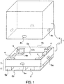
FIG. 1 is an exploded perspective view illustrating an example of a packing box to which a tipping indicator according to the present invention is fixed. - [
FIG. 2 ]
FIG. 2 is a perspective view illustrating a state in which a manufactured article (packed article) is packed in the packing box shown inFIG. 1 and a tipping indicator according to a first embodiment of the present invention is fixed to the packing box. - [
FIG. 3 ]
FIG. 3 is a front view illustrating structure of the tipping indicator according to the first embodiment shown inFIG. 2 . - [
FIG. 4 ]
FIG. 4 is a cross-sectional view illustrating structure of the tipping indicator according to the first embodiment shown inFIG. 2 . - [
FIG. 5 ]
FIG. 5 is a rear view illustrating structure of the tipping indicator according to the first embodiment shown inFIG. 2 . - [
FIG. 6 ]
FIG. 6 is a front view illustrating structure of an ink bag of the tipping indicator according to the first embodiment shown inFIG. 2 . - [
FIG. 7 ]
FIG. 7 is a front view illustrating a state in which an ink absorber is located on a front surface side of the ink bag of the tipping indicator according to the first embodiment shown inFIG. 2 . - [
FIG. 8 ]
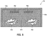
FIG. 8 is a front view illustrating structure of an outer bag of the tipping indicator according to the first embodiment shown inFIG. 2 . - [
FIG. 9 ]
FIG. 9 is a front view illustrating a state in which ink leaks from the ink bag of the tipping indicator according to the first embodiment shown inFIG. 2 and in which regions R3 of the outer bag change color. - [
FIG. 10 ]
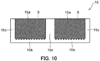
FIG. 10 is a front view illustrating structure of a variation of the ink bag according to the first embodiment shown inFIG. 2 . - [
FIG. 11 ]
FIG. 11 is a perspective view illustrating a state in which a manufactured article (packed article) is packed in the packing box shown inFIG. 1 and a tipping indicator according to a second embodiment of the present invention is fixed to the packing box. - [
FIG. 12 ]
FIG. 12 is a front view illustrating structure of the tipping indicator according to the second embodiment shown inFIG. 11 . - [
FIG. 13 ]
FIG. 13 is a cross-sectional view illustrating structure of the tipping indicator according to the second embodiment shown inFIG. 11 . - [
FIG. 14 ]
FIG. 14 is a rear view illustrating structure of the tipping indicator according to the second embodiment shown inFIG. 11 . - [
FIG. 15 ]
FIG. 15 is a front view illustrating structure of an ink bag of the tipping indicator according to the second embodiment shown inFIG. 11 . - [
FIG. 16 ]
FIG. 16 is a front view illustrating a state in which ink absorbers are located on a front surface side of ink bags of the tipping indicator according to the second embodiment shown inFIG. 11 . - [
FIG. 17 ]
FIG. 17 is a front view illustrating structure of an outer bag of the tipping indicator according to the second embodiment shown inFIG. 11 . - [
FIG. 18 ]
FIG. 18 is a front view illustrating a state in which ink only leaks from an ink bag in a first storage chamber of the tipping indicator according to the second embodiment shown inFIG. 11 and in which only regions R13 in the first storage chamber change color. - [
FIG. 19 ]
FIG. 19 is a front view illustrating a state in which ink only leaks from an ink bag in a second storage chamber of the tipping indicator according to the second embodiment shown inFIG. 11 and in which only regions R13 in the second storage chamber change color - [
FIG. 20 ]
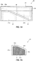
FIG. 20 is a front view illustrating structure of a first variation of the ink bag according to the second embodiment shown inFIG. 11 . - [
FIG. 21 ]
FIG. 21 is a front view illustrating structure of a second variation of the tipping indicator according to the second embodiment shown inFIG. 11 . - [
FIG. 22 ]
FIG. 22 is a rear view illustrating structure of the second variation of the tipping indicator according to the second embodiment shown inFIG. 11 . - The following explains embodiments of the present invention with reference to the drawings.
- First, a
packing box 1 to which a tipping indicator 10 (20) according to the present invention is attached, is explained with reference toFIG. 1 . - The
packing box 1 includes a tray-equippedpalette 2, anupper box 3, andcushioning 4. Theupper box 3 is a box that has an open bottom surface and also side and top surfaces that cover a packed article (manufactured article). Thecushioning 4 is located on thepalette 2 and is corrugated cardboard material that protects the packed article from external impact. Thecushioning 4 has a manufacturedarticle loading surface 4a that matches a shape of the packed article. - The tray-equipped
palette 2 includes atray 5 and apalette 6. Thetray 5 has abottom surface 5a on which the packed article (not illustrated) is loaded and aside wall 5b that stands upright along a periphery of thebottom surface 5a. Thepalette 6 is fixed to a lower surface of thetray 5. Thecushioning 4 is located at four corners of thebottom surface 5a, separated from theside wall 5b by a specific gap. Throughholes 8b are formed in a lower part of theupper box 3 at positions overlapping with throughholes 8a in theside wall 5b. The tray-equippedpalette 2 is connected to theupper box 3 by inserting a fastener with the throughholes - Raised parts (not illustrated) that are provided on the
bottom surface 5a are inserted into a lower surface of thecushioning 4. The raised parts fix each piece of thecushioning 4 in position so that thecushioning 4 does not become shifted in a horizontal direction. Note that thecushioning 4 may be fixed to thebottom surface 5a by a different method such as through adhesion. - The
palette 6 includes a plurality ofstruts 6a, a top plate (not illustrated), and abottom plate 6b. Thestruts 6a are for example formed from folded corrugated cardboard. The top plate is fixed to an upper surface of each of thestruts 6a and thebottom plate 6b is fixed to a lower surface of each of thestruts 6a. Arm insertion holes 9 through which an arm of a forklift truck or a hand lift (cart for palette conveyance) can be inserted are formed between thestruts 6a. - The following explains a procedure for packing a manufactured article using the
packing box 1 illustrated inFIG. 1 . First, the manufactured article (not illustrated) is placed on the manufacturedarticle loading surface 4a of thecushioning 4 located on thebottom surface 5a of the tray-equippedpalette 2. Next, after further cushioning has been placed on the side and top surfaces of the manufactured article as necessary, the manufactured article is covered by theupper box 3. - Finally, the tray-equipped
palette 2 is connected to theupper box 3 through insertion of fasteners 7 (refer toFIGS. 2 and11 ) in a state in which the throughholes 8a of theside wall 5b and the throughholes 8b of theupper box 3 are overlapping. Use of thepacking box 1 facilitates packing and transport-particularly of large manufactured articles and the like-because it is not necessary to load thepacking box 1 onto a palette after packing of the manufactured article. - Next, an explanation of the tipping
indicator 10 according to the first embodiment that is fixed to thepacking box 1 is provided with reference toFIGS. 2-9 . As illustrated inFIGS. 3-5 , the tippingindicator 10 includes anink bag 11, anink absorber 12, and anouter bag 13. Theink bag 11 includesink chambers 11a that are internally filled with an ink G. Theink absorber 12 is ink absorptive. Theouter bag 13 internally encloses theink bag 11 and theink absorber 12. Theink bag 11, theink absorber 12, and theouter bag 13 are flexible and are foldable into an L-shape. - With reference to
FIG. 6 , theink bag 11 is for example formed by a film made from a thermoplastic resin such as polyethylene, and has a substantially rectangular shape that is elongated in a specific direction (left-right direction inFIG. 6 ). Theink bag 11 is for example transparent. The ink G is for example red. Consequently, the ink G is visible from outside of theink bag 11. Note that theink bag 11 does not have to be transparent and may be semi-transparent or opaque, and may be subjected to printing on a surface thereof. The ink G (ink chambers 11a) is indicated by hatching inFIG. 6 . - The
ink chambers 11a internally filled with the ink G are provided separately on both sides-that is, one on each side-of a folding position M (central part in a longitudinal direction (left-right direction)) in the longitudinal direction. An upper edge of each of theink chambers 11a (one edge extending in the longitudinal direction) is formed by folding back of the film. A lower edge of each of theink chambers 11a (other edge extending in the longitudinal direction) is formed by a sealingpart 11b at which the film is sealed by heat sealing. Left and right edges of each of theink chambers 11a (edges extending in a lateral direction) are formed by sealingparts 11c at which the film is sealed by heat sealing. - The sealing
parts 11b are weak sealing sections that have a weaker sealing strength than the sealingparts 11c. More specifically, the sealingparts 11b are heat sealed at a lower temperature than the sealingparts 11c. For example, the sealingparts 11b are heat sealed at approximately 120°C and the sealingparts 11c are heat sealed at approximately 140°C. Therefore, theink bag 11 ruptures at the sealingparts 11b in response to application of external pressure on theink bag 11. - The
ink bag 11 has a weaker rupture strength than theouter bag 13. More specifically, at least the sealingparts 11b of theink bag 11 have a weaker sealing strength than a sealingpart 13b (refer toFIG. 8 ) of theouter bag 13 explained further below. In other words, theink bag 11 and theouter bag 13 are formed such that, in a situation in which tipping, etc., of thepacking box 1 occurs, theink bag 11 ruptures and the ink G leaks out, but theouter bag 13 does not rupture. Therefore, the ink G can be prevented from leaking out of theouter bag 13. Consequently, contamination of thepacking box 1 by the ink G can be prevented. - A manufacturing method of the
ink bag 11 involves folding back a film extending in the specific direction (longitudinal direction) at a central part thereof in the lateral direction (part that becomes the upper edges of theink chambers 11a) and subsequently heat sealing a part that becomes the lower edges ofink chambers 11a in order to form the sealingparts 11b. A tube-shaped film is formed as a result. Next, the sealingparts 11c and theink chambers 11a are formed by filling an inner part of the film with the ink G while performing heat sealing at specific intervals in the longitudinal direction. Subsequently, the sealingparts 11c are cut for each set of two intervals to manufacture theink bag 11 including the twoink chambers 11a. - As illustrated in
FIGS. 3 and4 , theink absorber 12 is located on a front surface side of the ink bag 11 (near side inFIG. 3 and upper side inFIG. 4 ). Theink absorber 12 is the same size or larger than theink bag 11 and is located on both sides in the left-right direction such as to span across the folding position M. Theink absorber 12 is formed from a material that can absorb the ink G (for example, a non-woven fabric). Theink absorber 12 has a different color from the ink G. In other words, theink absorber 12 is for example a color such as white that enables easy confirmation of a change of color when theink absorber 12 absorbs the ink G. As a result of theink absorber 12 being a color such as white, the color of the ink G in theink bag 11 is barely recognizable when viewed from a side corresponding to theink absorber 12 as illustrated inFIG. 7 . - The
outer bag 13 is for example formed from a transparent or semi-transparent film in which a thermoplastic resin layer is laminated onto the surface of a base material formed from PET (polyethylene terephthalate). Theouter bag 13 has a substantially rectangular shape that is elongated in the specific direction (left-right direction inFIG. 3 ). As illustrated inFIG. 4 , theouter bag 13 has astorage chamber 13a in which theink bag 11 and theink absorber 12 are enclosed. As illustrated inFIG. 8 , a lower edge of thestorage chamber 13a (one edge extending in the longitudinal direction) is formed by folding back of the film. Upper, left, and right edges of thestorage chamber 13a are formed by a sealingpart 13b at which the film is sealed by heat sealing. In the manner described above, thestorage chamber 13a is sealed with theink bag 11 and theink absorber 12 stored therein. - A front surface of the
outer bag 13 is subjected to specific printing as illustrated inFIG. 8 . Note that a region that is subjected to printing is indicated by hatching inFIG. 8 . More specifically, a region R1 (printed region) that occupies the majority of the front surface of theouter bag 13 is printed on with substantially the same color as the ink absorber 12 (herein, white). Regions R2 and regions R3 are provided on the front surface of theouter bag 13 on both sides in the longitudinal direction (left-right direction). The regions R2 are printed on with a different color from the region R1. The regions R3 are not subjected to printing. The regions R2 have, for example, a company name or logo printed therein. The regions R3 are regions in which theink absorber 12 is visible. The regions R3 are equivalent to an example of the "visual confirmation region". Each of the regions R3 includes a part therein that has been subjected to printing of substantially the same color as theink absorber 12. For example, characters or symbols that attract attention (herein, the characters "CRASH!") are printed. - Double-sided
adhesive tape 14 is attached to a rear surface of theouter bag 13 as illustrated inFIG. 5 . The double-sidedadhesive tape 14 adhesively fixes the tippingindicator 10 to a side surface of the packing box 1 (refer toFIG. 2 ). - As illustrated in
FIG. 2 , a pair of thetipping indicators 10 is fixed to opposite corners of thepacking box 1. Thetipping indicators 10 are each folded into an L-shape such that thetipping indicators 10 respectively span across opposite ridge lines L1 and L2 of the packing box 1 (upper box 3). When thepacking box 1 is to be transported, an arm of a forklift truck or a hand lift is inserted into the arm insertion holes 9 in the tray-equippedpalette 2, and thepacking box 1 is then lifted up and transported. - In a situation in which, during transportation, the
packing box 1 for some reason falls from the forklift truck or the hand lifter and tips, pressure is applied on one of thetipping indicators 10, theink bag 11 ruptures, and the ink G leaks out of theink bag 11. When the above occurs, the ink G that leaks out of theink bag 11 is absorbed by theink absorber 12, causing theink absorber 12 to change color, for example from white to red. As illustrated inFIG. 9 , because the regions R3 of theouter bag 13 change color, for example from white to red, the characters printed in the regions R3 (for example, the characters "CRASH!") become clearly visible. - In the first embodiment, the tipping
indicator 10 includes theink bag 11, theink absorber 12, and theouter bag 13 as explained above. Theink bag 11 is internally filled with the ink G. Theink absorber 12 is ink absorptive and has a different color from the ink G. Theouter bag 13 is formed from a film within which theink bag 11 and theink absorber 12 are enclosed. Theouter bag 13 has the regions R3 in which theink absorber 12 is visible. Therefore, theink bag 11 ruptures and the ink G leaks from theink bag 11 in a situation in which thepacking box 1 tips during transportation or storage, or in which thepacking box 1 is transported in a sideways state. Theink absorber 12 then absorbs the ink G and changes color. Consequently, it is possible to determine that tipping, etc., of thepacking box 1 has occurred, even if thepacking box 1 is subsequently lifted and returned to an original state. Therefore, in a situation in which the manufactured article (packed article) inside thepacking box 1 is damaged, it is easy to determine that the damage to the manufactured article (packed article) has occurred during transportation or storage. - Furthermore, the tipping
indicator 10 can be configured by theink bag 11, theink absorber 12, and theouter bag 13. Therefore, compared to the impact sensor-equipped cushioning disclosed inPTL 1, a simple configuration can be implemented through a simplified production process and with reduced production costs. In addition, a reduction in weight can be achieved because it is not necessary to provide a solution throughout cushioning. - As a result of the tipping
indicator 10 being fixed to the side surface of thepacking box 1, a person transporting thepacking box 1 can recognize that the tippingindicator 10 is present. Therefore, it is expected that an accident is less likely to occur during transportation because the person transporting thepacking box 1 will handle thepacking box 1 more carefully. - As explained above, the
ink bag 11 includes the sealingparts ink chamber 11a. The sealingparts 11b are weak sealing sections that have a weaker sealing strength than the sealingparts 11c. Therefore, theink bag 11 reliably ruptures at the sealingparts 11b when tipping, etc., of thepacking box 1 occurs. - As explained above, the
outer bag 13 has the region R1 that had been subjected to printing and that is adjacent to the regions R3 in which theink absorber 12 is visible. In addition, at least a part of the region R1 that borders the regions R3 has substantially the same color as the ink absorber 12 (the entirety of the region R1 in the present embodiment). Consequently, in a state in which theink absorber 12 has not changed color (i.e., a state in which tipping, etc., of thepacking box 1 has not occurred), boundaries between the region R1 and the regions R3 are difficult to recognize, and the region R1 and the regions R3 appear to be a single region. Furthermore, in a state in which theink absorber 12 has changed color (i.e., a state in which tipping, etc., of thepacking box 1 has occurred), the regions R3 change color to a different color from the region R1 such that the regions R3 are visually emphasized. Therefore, reliable visual confirmation that tipping, etc., of thepacking box 1 has occurred is possible. - As explained above, each of the regions R3 includes a part therein that has been subjected to printing of substantially the same color as the
ink absorber 12. Therefore, in a state in which theink absorber 12 has changed color (i.e., a state in which tipping, etc., of thepacking box 1 has occurred), printing of a different color to the regions R3 (for example, characters or symbols that attract attention) becomes clearly visible in the regions R3. Therefore, reliable visual confirmation that tipping, etc., of thepacking box 1 has occurred is possible. - As explained above, the
ink absorber 12 is made from a non-woven fabric. Therefore, theink absorber 12 is light and can be made cheaply. - As explained above, the
ink bag 11, theink absorber 12, and theouter bag 13 are foldable into an L-shape. Therefore, asingle tipping indicator 10 can be fixed to two adjacent side surfaces of thepacking box 1. Consequently, thesingle tipping indicator 10 can detect tipping, etc., in two different directions. - In the present embodiment, the pair of
tipping indicators 10 is fixed to opposite corners of thepacking box 1 such that thetipping indicators 10 respectively span across the opposite ridge lines L1 and L2 of thepacking box 1. Therefore, thetipping indicators 10 are fixed to all four side surfaces of thepacking box 1. Consequently, one of thetipping indicators 10 is ruptured whichever of the side surfaces of thepacking box 1 is underneath when thepacking box 1 tips, and a trace that an impact has occurred is reliably left in one of thetipping indicators 10 irrespective of which direction thepacking box 1 tips in. - As explained above, the
ink chambers 11a are located separately on both sides of the folding position M. Therefore, it is possible to prevent load being applied on theink chambers 11a and rupturing of theink chambers 11a during folding of theink bag 11, and thus a false detection of tipping, etc., of thepacking box 1 can be prevented. As theink chambers 11a are located separately on both sides of the folding position M, it is possible to determine which direction thepacking box 1 has tipped in by checking which of theink chambers 11a has ruptured. - As explained above, the
ink absorber 12 spans across the folding position M. Therefore, it is possible to confirm that tipping, etc., of thepacking box 1 has occurred from either of two adjacent side surfaces of thepacking box 1 because theink absorber 12 changes color across the two adjacent side surfaces of thepacking box 1. - Note that the presently disclosed first embodiment is merely an example in all aspects and should not be construed to be limiting. The scope of the present invention is indicated by the claims, rather than by the above-described first embodiment, and includes all variations that are equivalent in meaning and scope to the claims.
- Although the above first embodiment is explained for an example in which only one edge of each of the
ink chambers 11a has a weak sealing strength, the present invention is not limited to such an example. Two, three, or four edges of each of theink chambers 11a may alternatively have a weak sealing strength. - Although the above embodiment is explained for an example in which the sealing strength of the sealing
part 11b is weakened through heat sealing at a low temperature, the present invention is not limited to such an example. The sealing strength of a sealing part can alternatively be weakened through the type of film or the shape of the sealing part. For example, in anink bag 15 according to a variation of the present invention illustrated inFIG. 10 , sealingparts 15b have a weaker sealing strength because the sealingparts 15b are wave-shaped. Therefore, rupturing can occur more reliably at the sealingparts 15b when tipping, etc., of thepacking box 1 occurs. The sealing strength of a sealing part can also be weakened through viscosity of the ink G. More specifically, during formation of sealingparts 15c, heat sealing is performed while pressing films together such that ink G present between the films is pushed out. The ink G is less readily pushed out from between the films in a situation in which the ink G has higher viscosity. Therefore, the sealing strength of the sealingparts 15c can be made approximately the same as or weaker than the sealing strength of the sealingparts 15b by using an ink G having higher viscosity. - Although the above first embodiment is explained for an example in which the periphery of each of the
ink chambers 11a is sealed by heat sealing, the present invention is not limited to such an example. For example, the periphery of each of theink chambers 11a may be sealed by a zipper (also referred to as a zip or a fastener) or the like. The sealing strength of a sealing part can also be easily weakened in such a situation. - Although the above embodiment is explained for an example in which one type of
ink bag 11 is used, the present invention is not limited to such an example. For example, in a situation in which a plurality of different types ofink bags 11 having different rupture strengths are used and in which a different color ink G is used for each of the rupture strengths, the strength of impact can be determined based on which color theink absorber 12 changes to. - Although the above first embodiment is explained for an example in which the front surface of the
outer bag 13 has been subjected to printing, the present invention is not limited to such an example. The front surface of theouter bag 13 may alternatively not have been subjected to printing. In other words, the entire surface of theouter bag 13 may be transparent or semi-transparent. - Although the above first embodiment is explained for an example in which the
ink chambers 11a are located separately on both sides of the folding position M, anink chamber 11a that spans across the folding position M may alternatively be provided. - Although the above first embodiment is explained for an example in which the
ink absorber 12 spans across the folding position M,ink absorbers 12 located separately on both sides of the folding position M may alternatively be provided. - A configuration obtained through appropriate combination of configurations of the first embodiment described above and the variation illustrated in
FIG. 10 is also included in the technical scope of the present invention. - Next, an explanation is provided for a
tipping indicator 20 according to a second embodiment of the present invention that is fixed to apacking box 1. As illustrated inFIG. 11 , thepacking box 1 to which thetipping indicator 20 is fixed is the same as thepacking box 1 illustrated inFIG. 2 . As illustrated inFIGS. 12-14 , the tippingindicator 20 includesink bags 21, twoink absorber 22, and anouter bag 23. Theink bags 21 each include anink chamber 21a internally filled with ink G. The ink absorbers 22 are ink absorptive. Theouter bag 23 encloses theink bags 21 and theink absorbers 22 therein. Theink absorbers 22 and theouter bag 23 are flexible and can be folded into an L-shape. - Each of the
ink bags 21 is for example formed from a film made from a thermoplastic resin such as polyethylene. Theink bag 21 is for example transparent. The ink G is for example red. Therefore, the ink G is visible from outside of theink bag 21 as illustrated inFIG. 15 . Theink bag 21 does not have to be transparent and may be semi-transparent or opaque, or may be subjected to printing on a surface thereof. The ink G (ink chamber 21a) is indicated by hatching inFIG. 15 . - A lower edge of the
ink chamber 21a (one edge extending in a longitudinal direction) is formed by folding back of the film. An upper edge of theink chamber 21a is formed by a sealingpart 21b at which the film is sealed by heat sealing. Right and left edges of theink chamber 21a (edges extending in a lateral direction) are formed by sealingparts 21c at which the film is sealed by heat sealing. - The sealing
part 21b is a weak sealing section that has a weaker sealing strength than the sealingparts 21c. More specifically, the sealingpart 21b is heat sealed at a lower temperature than the sealingparts 21c. For example, the sealingpart 21b is heat sealed at approximately 120°C and the sealingparts 21c are heat sealed at approximately 140°C. Therefore, theink bag 21 ruptures at the sealingpart 21b in response to application of external pressure on theink bag 21. - The
ink bag 21 has a weaker rupture strength than theouter bag 23. In other words, at least the sealingpart 21b of theink bag 21 has a weaker sealing strength than a sealingpart 23c of theouter bag 23 explained further below. Theink bag 21 is formed such that when tipping, etc., of thepacking box 1 occurs, theink bag 21 ruptures and the ink G leaks out. In contrast, theouter bag 23 is formed such that theouter bag 23 does not rupture when tipping, etc., of thepacking box 1 occurs. Therefore, the ink G can be prevented from leaking out of theouter bag 23. Consequently, contamination of thepacking box 1 by the ink G can be prevented. - A manufacturing method of the
ink bag 21 involves folding back a film extending in the specific direction (longitudinal direction) at a central part thereof in the lateral direction (part that becomes the lower edge of theink chamber 21a) and subsequently heat sealing a part that becomes the upper edge of theink chamber 21a in order to form the sealingpart 21b. A tube-shaped film is formed as a result. Next, the sealingparts 21c and theink chamber 21a are formed by filling an inner part of the film with the ink G while performing heat sealing at specific intervals in the longitudinal direction. Subsequently, the sealingparts 21c are cut at each interval and an unnecessary part outside of (above) the sealingpart 21b is cut to manufacture theink bag 21 including theink chamber 21a. - As illustrated in
FIGS. 12 and 13 , each of theink absorbers 22 is located on a front surface side of the corresponding ink bag 21 (near side inFIG. 12 , upper side inFIG. 13 ). Theink absorber 22 is at least as large as theink bag 21. Theink absorber 22 is formed from a material that can absorb the ink G (for example, a non-woven fabric). Theink absorber 22 has a different color from the ink G. In other words, theink absorber 22 is for example a color such as white that enables easy confirmation of a change of color when theink absorber 22 absorbs the ink G. As a result of theink absorber 12 being a color such as white, the color of the ink G in theink bag 21 is barely recognizable when viewed from a side corresponding to theink absorber 22 as illustrated inFIG. 16 . - The
outer bag 23 is for example formed from a transparent or semi-transparent film in which a thermoplastic resin layer is laminated onto the surface of a base material formed from PET (polyethylene terephthalate). Theouter bag 23 has a substantially rectangular shape that is elongated in the specific direction (left-right direction inFIG. 12 ). As illustrated inFIGS. 12 and 13 , theouter bag 23 has afirst storage chamber 23a and asecond storage chamber 23b that each enclose anink bag 21 and anink absorber 22 therein. - As illustrated in
FIG. 12 , thefirst storage chamber 23a and thesecond storage chamber 23b each have a substantially triangular shape, for example, and each span across the folding position M such as to be located on both sides in the left-right direction. An area of a part of thefirst storage chamber 23a located on one side (left side) of the folding position M is larger than an area of a part of thefirst storage chamber 23a located on another side (right side) of the folding position M. An area of a part of thesecond storage chamber 23b located on the other side (right side) of the folding position M is larger than an area of a part of thesecond storage chamber 23b located on the one side (left side) of the folding position M. - As illustrated in
FIG. 14 , in thefirst storage chamber 23a, theink chamber 21a of theink bag 21 is located on only the one side (right side inFIG. 14 ) of the folding position M. In thesecond storage chamber 23b, theink chamber 21a of theink bag 21 is located on only the other side (left side inFIG. 14 ) of the folding position M. As illustrated inFIG. 12 , in each of thefirst storage chamber 23a and thesecond storage chamber 23b, theink absorber 22 spans across the folding position M such as to be located on both the left and right sides. - As illustrated in
FIG. 17 , a lower edge of the outer bag 23 (one edge extending in the longitudinal direction (left-right direction inFIG. 17 )) is formed by folding back of the film. Upper, left, and right edges of theouter bag 23, and a boundary between thefirst storage chamber 23a and thesecond storage chamber 23b are formed by sealingparts 23c at which the film is sealed by heat sealing. Through the above, thefirst storage chamber 23a and thesecond storage chamber 23b are each sealed with the correspondingink bag 21 and thecorresponding ink absorber 22 stored therein. The boundary between thefirst storage chamber 23a and thesecond storage chamber 23b is oblique to the folding position M. Therefore, thefirst storage chamber 23a and thesecond storage chamber 23b each have a width in an up-down direction that differs for the part on the left side (one side) compared to the part on the right side (other side), which easily restricts movement of thecorresponding ink bag 21 in the left-right direction. - A front surface of the
outer bag 23 is subjected to specific printing as illustrated inFIG. 17 . Note that a region that is subjected to printing is indicated by hatching inFIG. 17 . More specifically, a region R11 (printed region) that occupies the majority of the front surface of theouter bag 23 is printed on with substantially the same color as the ink absorbers 22 (herein, white). Regions R12 and regions R13 are provided on the front surface of theouter bag 23 on both sides in the longitudinal direction (left-right direction). The regions R12 are printed on with a different color from the region R11. The regions R13 are not subjected to printing. The regions R12 have, for example, a company name or logo printed therein. The regions R13 are regions in which theink absorbers 22 are visible. The regions R13 are equivalent to an example of the "visual confirmation region". - In each of the
first storage chamber 23a and thesecond storage chamber 23b, the regions R13 are located on both the left and right sides of the folding position M. In thefirst storage chamber 23a, an area of the region R13 on the left side (one side) of the folding position M is larger than an area of the region R13 on the right side (other side) of the folding position M. In thesecond storage chamber 23b, an area of the region R13 on the right side (other side) of the folding position M is larger than an area of the region R13 on the left side (one side) of the folding position M. The larger of the regions R13 includes a part therein that has been subjected to printing of substantially the same color as the correspondingink absorber 22. For example, characters or symbols that attract attention are printed (herein, the characters "CRASH!"). - Double-sided
adhesive tape 24 is attached to a rear surface of theouter bag 23 as illustrated inFIG. 14 . The double-sidedadhesive tape 24 adhesively fixes the tippingindicator 20 to a side surface of the packing box 1 (refer toFIG. 11 ). - As illustrated in
FIG. 11 , a pair of thetipping indicators 20 is fixed to opposite corners of thepacking box 1. Thetipping indicators 20 are each folded into an L-shape such that thetipping indicators 20 respectively span across opposite ridge lines L1 and L2 of the packing box 1 (upper box 3). When thepacking box 1 is to be transported, an arm of a forklift truck or a hand lift is inserted into the arm insertion holes 9 in the tray-equippedpalette 2, and thepacking box 1 is then lifted up and transported. - In a situation in which, during transportation, the
packing box 1 for some reason falls from the forklift truck or the hand lifter and tips, pressure is applied on one of thetipping indicators 20, one of theink bags 21 ruptures, and the ink G leaks out of theink bag 21. When the above occurs, the ink G that leaks out of theink bag 21 is absorbed by the correspondingink absorber 22, causing theink absorber 22 to change color, for example from white to red. As illustrated inFIGS. 18 and 19 , the corresponding regions R13 of theouter bag 23 change color, for example from white to red, and thus the characters printed in the regions R13 (for example, the characters "CRASH!") become clearly visible. - Note that in a situation in which the
packing box 1 tips in a direction of a side surface to which the one side (left side) of the tippingindicator 20 is attached, only theink bag 21 in thefirst storage chamber 23a ruptures and only the regions R13 in thefirst storage chamber 23a change color as illustrated inFIG. 18 . On the other hand, in a situation in which thepacking box 1 tips in a direction of a side surface to which the other side (right side) of the tippingindicator 20 is attached, only theink bag 21 in thesecond storage chamber 23b is ruptured and only the regions R13 in thesecond storage chamber 23b change color as illustrated inFIG. 19 . - In the second embodiment, the tipping
indicator 20 includes theink bags 21, theink absorbers 22, and theouter bag 23 as described above. Each of theink bags 21 is internally filled with the ink G. Each of theink absorbers 22 is ink absorptive and has a different color from the ink G. Theouter bag 23 is formed from a film within which theink bags 21 and theink absorbers 22 are enclosed. Theouter bag 23 has the regions R13 in which theink absorbers 22 are visible. Therefore, anink bag 21 ruptures and the ink G leaks from theink bag 21 in a situation in which thepacking box 1 tips during transportation or storage of thepacking box 1, or in which thepacking box 1 is transported in a sideways state. The correspondingink absorber 22 absorbs the ink G and changes color. Consequently, it is possible to determine that tipping, etc., of thepacking box 1 has occurred, even if thepacking box 1 is subsequently lifted and returned to an original state. Therefore, in a situation in which the manufactured article (packed article) inside thepacking box 1 is damaged, it is easy to determine that the damage to the manufactured article (packed article) has occurred during transportation or storage. - Furthermore, the tipping
indicator 20 can be configured by theink bags 21, theink absorbers 22, and theouter bag 23. Therefore, compared to the impact sensor-equipped cushioning disclosed inPTL 1, a simple configuration can be implemented through a simplified production process and with reduced production costs. In addition, a reduction in weight can be achieved because it is not necessary to provide a solution throughout cushioning - As a result of the tipping
indicator 20 being fixed to the side surface of thepacking box 1, a person transporting thepacking box 1 can recognize that the tippingindicator 20 is present. Therefore, it is expected that an accident is less likely to occur during transportation because the person transporting thepacking box 1 will handle thepacking box 1 more carefully. - The
ink absorbers 22 and theouter bag 23 are foldable into an L-shape. Therefore, asingle tipping indicator 20 can be fixed to two adjacent side surfaces of thepacking box 1. Consequently, thesingle tipping indicator 20 can detect tipping, etc., in two directions. - In the second embodiment, the pair of
tipping indicators 20 is fixed to opposite corners of thepacking box 1 such that thetipping indicators 20 respectively span across opposite ridge lines L1 and L2 of thepacking box 1. Therefore, thetipping indicators 20 are fixed to all four side surfaces of thepacking box 1. Consequently, one of thetipping indicators 20 is ruptured whichever of the side surfaces of thepacking box 1 is underneath when thepacking box 1 tips. Therefore, a trace that an impact has occurred is reliably left irrespective of which direction thepacking box 1 tips in. - In the
first storage chamber 23a, theink chamber 21a of theink bag 21 is only located on the one side of the folding position M, whereas in thesecond storage chamber 23b, theink chamber 21a of theink bag 21 is only located on the other side of the folding position M. Therefore, only theink bag 21 in thefirst storage chamber 23a or only theink bag 21 in thesecond storage chamber 23b ruptures when tipping, etc., of thepacking box 1 occurs and, as a result, only the regions R13 in thefirst storage chamber 23a or only the regions R13 in thesecond storage chamber 23b change color. Therefore, it is possible to determine which direction thepacking box 1 has tipped in. - In each of the
first storage chamber 23a and thesecond storage chamber 23b, theink absorber 22 is located on both sides of the folding position M. Also, in each of thefirst storage chamber 23a and thesecond storage chamber 23b, the regions R13 are located on both sides of the folding position M. Consequently, irrespective of which of the side surfaces having the tippingindicators 20 attached thereto thepacking box 1 tips toward, a correspondingink absorber 22 changes color over two adjacent sides of thepacking box 1. Therefore, it is possible to visually confirm that tipping, etc., of thepacking box 1 has occurred from either of the two adjacent side surfaces of thepacking box 1. - As explained above, in the
first storage chamber 23a, the area of the region R13 on the one side is larger than the area of the region R13 on the other side, whereas in thesecond storage chamber 23b, the area of the region R13 on the other side is larger than the area of the region R13 on the one side. Consequently, a color change occurs over a larger area on a side to which tipping has occurred than on a side to which tipping has not occurred. Therefore, an inspector, etc., can intuitively recognize which direction thepacking box 1 has tipped in. In the above manner, the tippingindicator 20 enables recognition of which direction thepacking box 1 has tipped in through a single glance from either of the two adjacent side surfaces of thepacking box 1. - As explained above, the area of the part of the
first storage chamber 23a on the one side is larger than the area of the part of thefirst storage chamber 23a on the other side, whereas the area of the part of thesecond storage chamber 23b on the other side is larger than the area of the part of thesecond storage chamber 23b on the one side. Therefore, thefirst storage chamber 23a and thesecond storage chamber 23b can each store alarger ink bag 21. Furthermore, the area of the region R13 on the one side of thefirst storage chamber 23a can easily be made larger than the area of the region R13 on the other side of thefirst storage chamber 23a, and the area of the region R13 on the other side of thesecond storage chamber 23b can easily be made larger than the area of the region R13 on the one side of thesecond storage chamber 23b. - As explained above, the boundary between the
first storage chamber 23a and thesecond storage chamber 23b is oblique to the folding position M. Therefore, theink bags 21 in thefirst storage chamber 23a and thesecond storage chamber 23b can be easily restricted from moving in the left-right direction. - As explained above, each of the
ink bags 21 includes the sealingparts ink chamber 21a, and the sealingpart 21b is a weak sealing section that has a weaker sealing strength than the sealingparts 21c. Therefore, theink bag 21 reliably ruptures at the sealingpart 21b when tipping, etc., of thepacking box 1 occurs. - As explained above, the
outer bag 23 has the region R11 that has been subjected to printing and that is adjacent to the regions R13 in which theink absorbers 12 are visible. At least parts of the region R11 that border the regions R13 have substantially the same color as the ink absorbers 22 (the entirety of the region R11 in the second embodiment). Consequently, in a state in which theink absorbers 22 have not changed color (i.e., a state in which tipping, etc., of thepacking box 1 has not occurred), boundaries between the region R11 and the regions R13 are difficult to recognize, and the region R11 and the regions R13 appear to be a single region. Furthermore, in a state in which one of theink absorbers 22 has changed color (i.e., a state in which tipping, etc., of thepacking box 1 has occurred), the corresponding regions R13 change color to a different color from the region R11 such that the regions R13 are visually emphasized. Therefore, reliable visual confirmation that tipping, etc., of thepacking box 1 has occurred is possible. - As explained above, part of the regions R13 is subjected to printing of substantially the same color as the
ink absorbers 22. Therefore, in a state in which thecorresponding ink absorber 22 has changed color (i.e., a state in which tipping, etc., of thepacking box 1 has occurred), printing of a different color from the regions R13 (for example, characters or symbols that attract attention) becomes clearly visible in the regions R13. Therefore, reliable visual confirmation that tipping, etc., of thepacking box 1 has occurred is possible. - As explained above, the
ink absorbers 22 are made from a non-woven fabric. Therefore, theink absorbers 22 are light and can be made cheaply. - Note that the presently disclosed second embodiment is merely an example in all aspects and should not be construed to be limiting. The scope of the present invention is indicated by the claims, rather than by the above-described second embodiment, and includes all variations that are equivalent in meaning and scope to the claims.
- Although the above second embodiment is explained for an example in which only the upper edge of the
ink chamber 21a has a weak sealing strength, the present invention is not limited to such an example. The left and right edges or all of the edges of theink chamber 21a may alternatively have a weaker sealing strength. - Although the above second embodiment is explained for an example in which the sealing strength of the sealing
part 21b is weakened through heat sealing at a low temperature, the present invention is not limited to such an example. The sealing strength of a sealing part can alternatively be weakened through the type of film or the shape of the sealing part. For example, in anink bag 21 according to a first variation of the present invention illustrated inFIG. 20 , a sealingpart 21b has a weaker sealing strength because the sealingpart 21b is wave-shaped. Therefore, rupturing can occur more reliably at the sealingpart 21b when tipping, etc., of thepacking box 1 occurs. The sealing strength of a sealing part can also be weakened through viscosity of the ink G. More specifically, during formation of the sealingparts 21c, heat sealing is performed while pressing films together such that ink G present between the films is pushed out. The ink G is less readily pushed out from between the films in a situation in which an ink G has higher viscosity. Therefore, the sealing strength of the sealingparts 21c can be made approximately the same or weaker than the sealing strength of the sealingpart 21b by using an ink G having higher viscosity. - Although the above second embodiment is explained for an example in which the periphery of each of the
ink chambers 21a is sealed by heat sealing, the present invention is not limited to such an example. For example, the periphery of each of theink chambers 11a may be sealed by a zipper (also referred to as a zip or a fastener) or the like. The sealing strength of a sealing part can also be easily weakened in such a situation. - Although the above second embodiment is explained for an example in which one type of
ink bag 21 is used, the present invention is not limited to such an example. For example, in a situation in which a plurality of different types ofink bags 21 having different rupture strengths are used and in which a different color ink G is used for each of the rupture strengths, the strength of impact can be determined based on which color anink absorber 22 changes to. - Although the above second embodiment is explained for an example in which the front surface of the
outer bag 23 has been subjected to printing, the present invention is not limited to such an example. The front surface of theouter bag 23 may alternatively not have been subjected to printing. In other words, the entire surface of theouter bag 23 may be transparent or semi-transparent. - Although the above second embodiment is explained for an example in which each of the
ink absorbers 22 spans across the folding position M,ink absorbers 22 located separately on both sides of the folding position M may alternatively be provided. In such a situation, theouter bag 23, theink absorbers 22, etc., are preferably formed such that theink absorbers 22 do not move in the left-right direction within thefirst storage chamber 23a or thesecond storage chamber 23b. - Although the above second embodiment is explained for an example in which the boundary between the
first storage chamber 23a and thesecond storage chamber 23b is oblique to the folding position M, the present invention is not limited to such an example. For example, a boundary between afirst storage chamber 23a and asecond storage chamber 23b may have a stepped-shape such as in atipping indicator 20 according to a second variation of the present invention illustrated inFIGS. 21 and22 . In such a situation, thefirst storage chamber 23a and thesecond storage chamber 23b each have a part on one side and a part on another side that differ in terms of width in the up-down direction and, as a result, anink bag 21 is easily restricted from moving in the left-right direction. Note that the double-sidedadhesive tape 24 is omitted inFIG. 22 . A boundary between afirst storage chamber 23a and asecond storage chamber 23b may alternatively be parallel to upper and lower edges of thefirst storage chamber 23a and thesecond storage chamber 23b. In other words, thefirst storage chamber 23a and thesecond storage chamber 23b may each have a thin substantially rectangular shape and may be arranged in the up-down direction. - The above second embodiment is explained for an example in which, in each of the
first storage chamber 23a and thesecond storage chamber 23b, the region R13 (visual confirmation region) on the side on which theink chamber 21a is located has a larger area so that it is possible to intuitively recognize the direction in which tipping, etc., of thepacking box 1 has occurred. However, the present invention is not limited to such an example. The regions R13 on the left and right sides may alternatively be the same size. In such a situation, theouter bag 23 may be subjected to printing that indicates a tipping direction (for example, the characters "Left side surface impact detection window") in the regions R13 or in proximity thereto. Through such a configuration, an inspector, etc., can easily recognize in which direction tipping, etc., of thepacking box 1 has occurred, even if thefirst storage chamber 23a, thesecond storage chamber 23b, and the regions R13 are the same size on both the left and right sides. Note that printing indicating the tipping direction may be performed even in a situation in which thefirst storage chamber 23a, thesecond storage chamber 23b, and the regions R13 are different sizes on the left and right sides as in the above embodiment. - A configuration obtained through appropriate combination of configurations of the above-described second embodiment, first variation, and second variation is also included in the technical scope of the present invention.
- In the above first and second embodiments, as explained using
FIG. 1 , theside wall 5b of thetray 5 has a flap-shape that is foldable relative to thebottom surface 5a, and theside wall 5b is stood up after covering with theupper box 3 and is connected to theupper box 3 with fasteners. Alternatively, theside wall 5b may be partly or entirely omitted and the tray-equippedpalette 2 may be fixed to theupper box 3 by a tie-band or the like. In the above first and second embodiments, as explained usingFIG. 1 , an example is given in which thepacking box 1 includes the tray-equippedpalette 2 formed by thetray 5 and thepalette 6. However, the present invention can of course also be applied in the same way to apacking box 1 formed by anupper box 3 and atray 5, without apalette 6.
Claims (15)
- A tipping indicator for fixing to a side surface of a packing box, the tipping indicator comprising:an ink bag including an ink chamber internally filled with an ink;an ink absorber that is ink absorptive and that has a different color from the ink; andan outer bag formed from a film within which the ink bag and the ink absorber are enclosed, whereinat least part of the outer bag has a visual confirmation region in which the ink absorber is visible.
- The tipping indicator according to claim 1, wherein
the ink bag includes a sealing part that seals a periphery of the ink chamber, and
the sealing part includes a weak sealing section that has a weaker sealing strength than another section of the sealing part. - The tipping indicator according to claim 1, wherein
the outer bag has a printed region that has been subjected to printing and that is adjacent to the visual confirmation region, and
at least a part of the printed region that borders the visual confirmation region has substantially the same color as the ink absorber. - The tipping indicator according to claim 3, wherein
the visual confirmation region includes a part therein that has been subjected to printing of substantially the same color as the ink absorber. - The tipping indicator according to claim 1, wherein
the ink absorber is made from a non-woven fabric. - The tipping indicator according to claim 1, wherein
the ink bag, the ink absorber, and the outer bag are foldable into an L-shape. - The tipping indicator according to claim 6, wherein
the ink chamber is provided as a plurality of ink chambers that are located separately on both sides of a folding position. - The tipping indicator according to claim 6, wherein
the ink absorber spans across a folding position. - The tipping indicator according to claim 1, wherein
the outer bag includes a first storage chamber and a second storage chamber that enclose the ink absorber therein,
the ink absorber and the outer bag are foldable into an L-shape,
the first storage chamber and the second storage chamber each span across a folding position,
in the first storage chamber, the ink chamber of the ink bag is located on only one side of the folding position,
in the second storage chamber, the ink chamber of the ink bag is located on only another side of the folding position,
in the first storage chamber and the second storage chamber, the ink absorber is located on both the one side and the other side of the folding position, and
in the first storage chamber and the second storage chamber, the visual confirmation region is located on both the one side and the other side of the folding position. - The tipping indicator according to claim 9, wherein
in the first storage chamber, an area of the visual confirmation region on the one side of the folding position is larger than an area of the visual confirmation region on the other side of the folding position, and
in the second storage chamber, an area of the visual confirmation region on the other side of the folding position is larger than an area of the visual confirmation region on the one side of the folding position. - The tipping indicator according to claim 9, wherein
an area of a part of the first storage chamber located on the one side of the folding position is larger than an area of a part of the first storage chamber located on the other side of the folding position, and
an area of a part of the second storage chamber located on the other side of the folding position is larger than an area of a part of the second storage chamber located on the one side of the folding position. - The tipping indicator according to claim 9, wherein
a boundary between the first storage chamber and the second storage chamber is oblique to the folding position or has a stepped-shape. - The tipping indicator according to claim 9, wherein
the ink bag includes a sealing part that seals a periphery of the ink chamber, and
the sealing part includes a weak sealing section that has a weaker sealing strength than another section of the sealing part. - The tipping indicator according to claim 9, wherein
the outer bag has been subjected to printing that indicates a tipping direction. - A packing box having the tipping indicator according to claim 1 fixed thereto.
Applications Claiming Priority (3)
| Application Number | Priority Date | Filing Date | Title |
|---|---|---|---|
| JP2014092411 | 2014-04-28 | ||
| JP2014108797 | 2014-05-27 | ||
| PCT/JP2015/061241 WO2015166786A1 (en) | 2014-04-28 | 2015-04-10 | Falling indicator and packaging box provided with same |
Publications (3)
| Publication Number | Publication Date |
|---|---|
| EP3139144A1 true EP3139144A1 (en) | 2017-03-08 |
| EP3139144A4 EP3139144A4 (en) | 2018-01-03 |
| EP3139144B1 EP3139144B1 (en) | 2019-02-13 |
Family
ID=54358521
Family Applications (1)
| Application Number | Title | Priority Date | Filing Date |
|---|---|---|---|
| EP15786629.4A Not-in-force EP3139144B1 (en) | 2014-04-28 | 2015-04-10 | Falling indicator and packaging box provided with same |
Country Status (5)
| Country | Link |
|---|---|
| US (1) | US9952069B2 (en) |
| EP (1) | EP3139144B1 (en) |
| JP (1) | JP6059850B2 (en) |
| CN (1) | CN105452828B (en) |
| WO (1) | WO2015166786A1 (en) |
Families Citing this family (6)
| Publication number | Priority date | Publication date | Assignee | Title |
|---|---|---|---|---|
| JP6392713B2 (en) * | 2015-07-29 | 2018-09-19 | ファナック株式会社 | Motor drive device capable of reporting cutting fluid adhesion |
| DE102016100573A1 (en) | 2016-01-14 | 2017-07-20 | Schreiner Group Gmbh & Co. Kg | Shock sensor for detecting a shock or other acceleration |
| US10189626B2 (en) | 2017-05-23 | 2019-01-29 | Reuben Bahar | Package handling system |
| DE102017211179A1 (en) * | 2017-06-30 | 2019-01-03 | Robert Bosch Gmbh | Measuring device and measuring method |
| CN109649797B (en) * | 2018-11-06 | 2021-01-01 | 惠州市华星光电技术有限公司 | Box inclination detection device and packing box |
| JP2024057172A (en) * | 2022-10-12 | 2024-04-24 | 株式会社竹中土木 | Pressure Measuring Device |
Family Cites Families (12)
| Publication number | Priority date | Publication date | Assignee | Title |
|---|---|---|---|---|
| US3243303A (en) * | 1962-06-27 | 1966-03-29 | Leighton C Johnson | Temperature monitor employing a flowable aqueous composition containing dispersed polyvinyl acetate as a flow retardant |
| US3207122A (en) * | 1964-02-05 | 1965-09-21 | Paul M Smith | Means and techniques for indicating condition of shipped articles |
| US4340008A (en) * | 1980-09-22 | 1982-07-20 | Mendelson Ralph R | Tilt indicator for shipping containers |
| US6367408B1 (en) * | 2000-04-27 | 2002-04-09 | Jing Lu Gu | En route rage sensing apparatus |
| CN1668927A (en) * | 2002-06-14 | 2005-09-14 | 3M创新有限公司 | Shock indicator |
| US20080099479A1 (en) * | 2006-10-31 | 2008-05-01 | Liu Calvin Y | Damage indication systems and methods |
| CN201132638Y (en) * | 2007-12-28 | 2008-10-15 | 潮州市佳业食品有限公司 | sealed box |
| JP5042185B2 (en) | 2008-09-30 | 2012-10-03 | トッパン・フォームズ株式会社 | Shock absorber with shock sensor |
| CN201355249Y (en) * | 2009-02-17 | 2009-12-02 | 严少敏 | Object tilting monitor |
| CN201721697U (en) * | 2010-05-10 | 2011-01-26 | 深圳市力多威电池有限公司 | Packing box |
| JP2014043245A (en) * | 2012-08-24 | 2014-03-13 | Kyocera Document Solutions Inc | Impact indicator and packing box including the same |
| JP5781117B2 (en) * | 2013-03-29 | 2015-09-16 | 京セラドキュメントソリューションズ株式会社 | Impact detection device |
-
2015
- 2015-04-10 EP EP15786629.4A patent/EP3139144B1/en not_active Not-in-force
- 2015-04-10 US US14/906,049 patent/US9952069B2/en not_active Expired - Fee Related
- 2015-04-10 CN CN201580001413.4A patent/CN105452828B/en not_active Expired - Fee Related
- 2015-04-10 WO PCT/JP2015/061241 patent/WO2015166786A1/en not_active Ceased
- 2015-04-10 JP JP2016515918A patent/JP6059850B2/en not_active Expired - Fee Related
Also Published As
| Publication number | Publication date |
|---|---|
| CN105452828B (en) | 2018-01-05 |
| US9952069B2 (en) | 2018-04-24 |
| EP3139144A4 (en) | 2018-01-03 |
| CN105452828A (en) | 2016-03-30 |
| US20160161297A1 (en) | 2016-06-09 |
| JPWO2015166786A1 (en) | 2017-04-20 |
| EP3139144B1 (en) | 2019-02-13 |
| JP6059850B2 (en) | 2017-01-11 |
| WO2015166786A1 (en) | 2015-11-05 |
Similar Documents
| Publication | Publication Date | Title |
|---|---|---|
| EP3139144B1 (en) | Falling indicator and packaging box provided with same | |
| ES2907680T3 (en) | Reinforced container, cardboard box, combination of a cardboard box preform and a bag, and method of forming a reinforced container | |
| US8167489B2 (en) | Packaging bag for secondary packaging configured to transport infectious substances | |
| CA2746906A1 (en) | Takeout food bag | |
| US8820532B2 (en) | Leak-proof packaging for wet batteries | |
| US10807783B2 (en) | Package handling system | |
| TR201811679T4 (en) | Enclosure with means for improved closing. | |
| US20120180434A1 (en) | Tamper-evident bag for protecting luggage, allowing inspection and reclosure, and methods | |
| JP5209423B2 (en) | Pellicle packing structure | |
| JP5327995B1 (en) | Manufacturing method of horizontal gusset bag with hanging header | |
| CA2869307C (en) | Leak-proof packaging for wet batteries | |
| KR101753084B1 (en) | Air package by duplex structure | |
| CN105480572B (en) | A kind of packaging bed course of automatic Leakage Detection | |
| JP2006069621A (en) | Packaging member | |
| US20060272288A1 (en) | Small box shipper with internal inflatable bag | |
| JP2012020764A (en) | Storage bag and packing structure of storage bag | |
| JP6047879B2 (en) | Package | |
| CN221758237U (en) | Multi-groove reagent packaging bag | |
| JP6180835B2 (en) | Product packaging bags and bags | |
| CN206590237U (en) | A kind of packing box | |
| JP3036760U (en) | Fruit and vegetable packaging and packaging material for fruits and vegetables | |
| JP6566617B2 (en) | Combination container package, inner container package and inner container | |
| JP5104433B2 (en) | Package | |
| JP2014043245A (en) | Impact indicator and packing box including the same | |
| JP2010111409A (en) | Packaging bubble sheet body and packaging bubble board body |
Legal Events
| Date | Code | Title | Description |
|---|---|---|---|
| STAA | Information on the status of an ep patent application or granted ep patent |
Free format text: STATUS: THE INTERNATIONAL PUBLICATION HAS BEEN MADE |
|
| PUAI | Public reference made under article 153(3) epc to a published international application that has entered the european phase |
Free format text: ORIGINAL CODE: 0009012 |
|
| STAA | Information on the status of an ep patent application or granted ep patent |
Free format text: STATUS: REQUEST FOR EXAMINATION WAS MADE |
|
| 17P | Request for examination filed |
Effective date: 20160120 |
|
| AK | Designated contracting states |
Kind code of ref document: A1 Designated state(s): AL AT BE BG CH CY CZ DE DK EE ES FI FR GB GR HR HU IE IS IT LI LT LU LV MC MK MT NL NO PL PT RO RS SE SI SK SM TR |
|
| AX | Request for extension of the european patent |
Extension state: BA ME |
|
| DAV | Request for validation of the european patent (deleted) | ||
| DAX | Request for extension of the european patent (deleted) | ||
| A4 | Supplementary search report drawn up and despatched |
Effective date: 20171201 |
|
| RIC1 | Information provided on ipc code assigned before grant |
Ipc: G01P 15/00 20060101ALI20171127BHEP Ipc: B65D 25/20 20060101ALI20171127BHEP Ipc: G01L 1/00 20060101AFI20171127BHEP Ipc: G01L 5/00 20060101ALI20171127BHEP |
|
| GRAP | Despatch of communication of intention to grant a patent |
Free format text: ORIGINAL CODE: EPIDOSNIGR1 |
|
| STAA | Information on the status of an ep patent application or granted ep patent |
Free format text: STATUS: GRANT OF PATENT IS INTENDED |
|
| INTG | Intention to grant announced |
Effective date: 20180827 |
|
| GRAS | Grant fee paid |
Free format text: ORIGINAL CODE: EPIDOSNIGR3 |
|
| GRAA | (expected) grant |
Free format text: ORIGINAL CODE: 0009210 |
|
| STAA | Information on the status of an ep patent application or granted ep patent |
Free format text: STATUS: THE PATENT HAS BEEN GRANTED |
|
| AK | Designated contracting states |
Kind code of ref document: B1 Designated state(s): AL AT BE BG CH CY CZ DE DK EE ES FI FR GB GR HR HU IE IS IT LI LT LU LV MC MK MT NL NO PL PT RO RS SE SI SK SM TR |
|
| REG | Reference to a national code |
Ref country code: GB Ref legal event code: FG4D |
|
| REG | Reference to a national code |
Ref country code: CH Ref legal event code: EP Ref country code: AT Ref legal event code: REF Ref document number: 1096490 Country of ref document: AT Kind code of ref document: T Effective date: 20190215 |
|
| REG | Reference to a national code |
Ref country code: IE Ref legal event code: FG4D |
|
| REG | Reference to a national code |
Ref country code: DE Ref legal event code: R096 Ref document number: 602015024644 Country of ref document: DE |
|
| REG | Reference to a national code |
Ref country code: LT Ref legal event code: MG4D |
|
| REG | Reference to a national code |
Ref country code: NL Ref legal event code: MP Effective date: 20190213 |
|
| PG25 | Lapsed in a contracting state [announced via postgrant information from national office to epo] |
Ref country code: PT Free format text: LAPSE BECAUSE OF FAILURE TO SUBMIT A TRANSLATION OF THE DESCRIPTION OR TO PAY THE FEE WITHIN THE PRESCRIBED TIME-LIMIT Effective date: 20190613 Ref country code: SE Free format text: LAPSE BECAUSE OF FAILURE TO SUBMIT A TRANSLATION OF THE DESCRIPTION OR TO PAY THE FEE WITHIN THE PRESCRIBED TIME-LIMIT Effective date: 20190213 Ref country code: NL Free format text: LAPSE BECAUSE OF FAILURE TO SUBMIT A TRANSLATION OF THE DESCRIPTION OR TO PAY THE FEE WITHIN THE PRESCRIBED TIME-LIMIT Effective date: 20190213 Ref country code: LT Free format text: LAPSE BECAUSE OF FAILURE TO SUBMIT A TRANSLATION OF THE DESCRIPTION OR TO PAY THE FEE WITHIN THE PRESCRIBED TIME-LIMIT Effective date: 20190213 Ref country code: NO Free format text: LAPSE BECAUSE OF FAILURE TO SUBMIT A TRANSLATION OF THE DESCRIPTION OR TO PAY THE FEE WITHIN THE PRESCRIBED TIME-LIMIT Effective date: 20190513 Ref country code: FI Free format text: LAPSE BECAUSE OF FAILURE TO SUBMIT A TRANSLATION OF THE DESCRIPTION OR TO PAY THE FEE WITHIN THE PRESCRIBED TIME-LIMIT Effective date: 20190213 |
|
| PG25 | Lapsed in a contracting state [announced via postgrant information from national office to epo] |
Ref country code: IS Free format text: LAPSE BECAUSE OF FAILURE TO SUBMIT A TRANSLATION OF THE DESCRIPTION OR TO PAY THE FEE WITHIN THE PRESCRIBED TIME-LIMIT Effective date: 20190613 Ref country code: BG Free format text: LAPSE BECAUSE OF FAILURE TO SUBMIT A TRANSLATION OF THE DESCRIPTION OR TO PAY THE FEE WITHIN THE PRESCRIBED TIME-LIMIT Effective date: 20190513 Ref country code: LV Free format text: LAPSE BECAUSE OF FAILURE TO SUBMIT A TRANSLATION OF THE DESCRIPTION OR TO PAY THE FEE WITHIN THE PRESCRIBED TIME-LIMIT Effective date: 20190213 Ref country code: RS Free format text: LAPSE BECAUSE OF FAILURE TO SUBMIT A TRANSLATION OF THE DESCRIPTION OR TO PAY THE FEE WITHIN THE PRESCRIBED TIME-LIMIT Effective date: 20190213 Ref country code: GR Free format text: LAPSE BECAUSE OF FAILURE TO SUBMIT A TRANSLATION OF THE DESCRIPTION OR TO PAY THE FEE WITHIN THE PRESCRIBED TIME-LIMIT Effective date: 20190514 Ref country code: HR Free format text: LAPSE BECAUSE OF FAILURE TO SUBMIT A TRANSLATION OF THE DESCRIPTION OR TO PAY THE FEE WITHIN THE PRESCRIBED TIME-LIMIT Effective date: 20190213 |
|
| REG | Reference to a national code |
Ref country code: AT Ref legal event code: MK05 Ref document number: 1096490 Country of ref document: AT Kind code of ref document: T Effective date: 20190213 |
|
| PG25 | Lapsed in a contracting state [announced via postgrant information from national office to epo] |
Ref country code: CZ Free format text: LAPSE BECAUSE OF FAILURE TO SUBMIT A TRANSLATION OF THE DESCRIPTION OR TO PAY THE FEE WITHIN THE PRESCRIBED TIME-LIMIT Effective date: 20190213 Ref country code: IT Free format text: LAPSE BECAUSE OF FAILURE TO SUBMIT A TRANSLATION OF THE DESCRIPTION OR TO PAY THE FEE WITHIN THE PRESCRIBED TIME-LIMIT Effective date: 20190213 Ref country code: RO Free format text: LAPSE BECAUSE OF FAILURE TO SUBMIT A TRANSLATION OF THE DESCRIPTION OR TO PAY THE FEE WITHIN THE PRESCRIBED TIME-LIMIT Effective date: 20190213 Ref country code: SK Free format text: LAPSE BECAUSE OF FAILURE TO SUBMIT A TRANSLATION OF THE DESCRIPTION OR TO PAY THE FEE WITHIN THE PRESCRIBED TIME-LIMIT Effective date: 20190213 Ref country code: AL Free format text: LAPSE BECAUSE OF FAILURE TO SUBMIT A TRANSLATION OF THE DESCRIPTION OR TO PAY THE FEE WITHIN THE PRESCRIBED TIME-LIMIT Effective date: 20190213 Ref country code: DK Free format text: LAPSE BECAUSE OF FAILURE TO SUBMIT A TRANSLATION OF THE DESCRIPTION OR TO PAY THE FEE WITHIN THE PRESCRIBED TIME-LIMIT Effective date: 20190213 Ref country code: EE Free format text: LAPSE BECAUSE OF FAILURE TO SUBMIT A TRANSLATION OF THE DESCRIPTION OR TO PAY THE FEE WITHIN THE PRESCRIBED TIME-LIMIT Effective date: 20190213 Ref country code: ES Free format text: LAPSE BECAUSE OF FAILURE TO SUBMIT A TRANSLATION OF THE DESCRIPTION OR TO PAY THE FEE WITHIN THE PRESCRIBED TIME-LIMIT Effective date: 20190213 |
|
| REG | Reference to a national code |
Ref country code: DE Ref legal event code: R097 Ref document number: 602015024644 Country of ref document: DE |
|
| PG25 | Lapsed in a contracting state [announced via postgrant information from national office to epo] |
Ref country code: SM Free format text: LAPSE BECAUSE OF FAILURE TO SUBMIT A TRANSLATION OF THE DESCRIPTION OR TO PAY THE FEE WITHIN THE PRESCRIBED TIME-LIMIT Effective date: 20190213 Ref country code: PL Free format text: LAPSE BECAUSE OF FAILURE TO SUBMIT A TRANSLATION OF THE DESCRIPTION OR TO PAY THE FEE WITHIN THE PRESCRIBED TIME-LIMIT Effective date: 20190213 |
|
| REG | Reference to a national code |
Ref country code: CH Ref legal event code: PL |
|
| REG | Reference to a national code |
Ref country code: BE Ref legal event code: MM Effective date: 20190430 |
|
| PLBE | No opposition filed within time limit |
Free format text: ORIGINAL CODE: 0009261 |
|
| STAA | Information on the status of an ep patent application or granted ep patent |
Free format text: STATUS: NO OPPOSITION FILED WITHIN TIME LIMIT |
|
| PG25 | Lapsed in a contracting state [announced via postgrant information from national office to epo] |
Ref country code: LU Free format text: LAPSE BECAUSE OF NON-PAYMENT OF DUE FEES Effective date: 20190410 Ref country code: MC Free format text: LAPSE BECAUSE OF FAILURE TO SUBMIT A TRANSLATION OF THE DESCRIPTION OR TO PAY THE FEE WITHIN THE PRESCRIBED TIME-LIMIT Effective date: 20190213 Ref country code: AT Free format text: LAPSE BECAUSE OF FAILURE TO SUBMIT A TRANSLATION OF THE DESCRIPTION OR TO PAY THE FEE WITHIN THE PRESCRIBED TIME-LIMIT Effective date: 20190213 |
|
| 26N | No opposition filed |
Effective date: 20191114 |
|
| PG25 | Lapsed in a contracting state [announced via postgrant information from national office to epo] |
Ref country code: LI Free format text: LAPSE BECAUSE OF NON-PAYMENT OF DUE FEES Effective date: 20190430 Ref country code: CH Free format text: LAPSE BECAUSE OF NON-PAYMENT OF DUE FEES Effective date: 20190430 |
|
| PG25 | Lapsed in a contracting state [announced via postgrant information from national office to epo] |
Ref country code: SI Free format text: LAPSE BECAUSE OF FAILURE TO SUBMIT A TRANSLATION OF THE DESCRIPTION OR TO PAY THE FEE WITHIN THE PRESCRIBED TIME-LIMIT Effective date: 20190213 Ref country code: BE Free format text: LAPSE BECAUSE OF NON-PAYMENT OF DUE FEES Effective date: 20190430 |
|
| PG25 | Lapsed in a contracting state [announced via postgrant information from national office to epo] |
Ref country code: TR Free format text: LAPSE BECAUSE OF FAILURE TO SUBMIT A TRANSLATION OF THE DESCRIPTION OR TO PAY THE FEE WITHIN THE PRESCRIBED TIME-LIMIT Effective date: 20190213 |
|
| PG25 | Lapsed in a contracting state [announced via postgrant information from national office to epo] |
Ref country code: IE Free format text: LAPSE BECAUSE OF NON-PAYMENT OF DUE FEES Effective date: 20190410 |
|
| PG25 | Lapsed in a contracting state [announced via postgrant information from national office to epo] |
Ref country code: CY Free format text: LAPSE BECAUSE OF FAILURE TO SUBMIT A TRANSLATION OF THE DESCRIPTION OR TO PAY THE FEE WITHIN THE PRESCRIBED TIME-LIMIT Effective date: 20190213 |
|
| PG25 | Lapsed in a contracting state [announced via postgrant information from national office to epo] |
Ref country code: HU Free format text: LAPSE BECAUSE OF FAILURE TO SUBMIT A TRANSLATION OF THE DESCRIPTION OR TO PAY THE FEE WITHIN THE PRESCRIBED TIME-LIMIT; INVALID AB INITIO Effective date: 20150410 Ref country code: MT Free format text: LAPSE BECAUSE OF FAILURE TO SUBMIT A TRANSLATION OF THE DESCRIPTION OR TO PAY THE FEE WITHIN THE PRESCRIBED TIME-LIMIT Effective date: 20190213 |
|
| PG25 | Lapsed in a contracting state [announced via postgrant information from national office to epo] |
Ref country code: MK Free format text: LAPSE BECAUSE OF FAILURE TO SUBMIT A TRANSLATION OF THE DESCRIPTION OR TO PAY THE FEE WITHIN THE PRESCRIBED TIME-LIMIT Effective date: 20190213 |
|
| PGFP | Annual fee paid to national office [announced via postgrant information from national office to epo] |
Ref country code: FR Payment date: 20230321 Year of fee payment: 9 |
|
| PGFP | Annual fee paid to national office [announced via postgrant information from national office to epo] |
Ref country code: GB Payment date: 20230321 Year of fee payment: 9 |
|
| P01 | Opt-out of the competence of the unified patent court (upc) registered |
Effective date: 20230420 |
|
| PGFP | Annual fee paid to national office [announced via postgrant information from national office to epo] |
Ref country code: DE Payment date: 20230321 Year of fee payment: 9 |
|
| REG | Reference to a national code |
Ref country code: DE Ref legal event code: R119 Ref document number: 602015024644 Country of ref document: DE |
|
| GBPC | Gb: european patent ceased through non-payment of renewal fee |
Effective date: 20240410 |
|
| PG25 | Lapsed in a contracting state [announced via postgrant information from national office to epo] |
Ref country code: DE Free format text: LAPSE BECAUSE OF NON-PAYMENT OF DUE FEES Effective date: 20241105 |
|
| PG25 | Lapsed in a contracting state [announced via postgrant information from national office to epo] |
Ref country code: GB Free format text: LAPSE BECAUSE OF NON-PAYMENT OF DUE FEES Effective date: 20240410 |
|
| PG25 | Lapsed in a contracting state [announced via postgrant information from national office to epo] |
Ref country code: FR Free format text: LAPSE BECAUSE OF NON-PAYMENT OF DUE FEES Effective date: 20240430 |
|
| PG25 | Lapsed in a contracting state [announced via postgrant information from national office to epo] |
Ref country code: GB Free format text: LAPSE BECAUSE OF NON-PAYMENT OF DUE FEES Effective date: 20240410 Ref country code: FR Free format text: LAPSE BECAUSE OF NON-PAYMENT OF DUE FEES Effective date: 20240430 Ref country code: DE Free format text: LAPSE BECAUSE OF NON-PAYMENT OF DUE FEES Effective date: 20241105 |