EP3139128A1 - A calibration method for magnetic field sensing devices, corresponding system, apparatus and computer program product - Google Patents
A calibration method for magnetic field sensing devices, corresponding system, apparatus and computer program product Download PDFInfo
- Publication number
- EP3139128A1 EP3139128A1 EP16161413.6A EP16161413A EP3139128A1 EP 3139128 A1 EP3139128 A1 EP 3139128A1 EP 16161413 A EP16161413 A EP 16161413A EP 3139128 A1 EP3139128 A1 EP 3139128A1
- Authority
- EP
- European Patent Office
- Prior art keywords
- signal components
- graph
- magnetic field
- ellipsoidal
- unc
- Prior art date
- Legal status (The legal status is an assumption and is not a legal conclusion. Google has not performed a legal analysis and makes no representation as to the accuracy of the status listed.)
- Granted
Links
Images
Classifications
-
- G—PHYSICS
- G01—MEASURING; TESTING
- G01R—MEASURING ELECTRIC VARIABLES; MEASURING MAGNETIC VARIABLES
- G01R33/00—Arrangements or instruments for measuring magnetic variables
- G01R33/0023—Electronic aspects, e.g. circuits for stimulation, evaluation, control; Treating the measured signals; calibration
- G01R33/0035—Calibration of single magnetic sensors, e.g. integrated calibration
-
- G—PHYSICS
- G01—MEASURING; TESTING
- G01C—MEASURING DISTANCES, LEVELS OR BEARINGS; SURVEYING; NAVIGATION; GYROSCOPIC INSTRUMENTS; PHOTOGRAMMETRY OR VIDEOGRAMMETRY
- G01C17/00—Compasses; Devices for ascertaining true or magnetic north for navigation or surveying purposes
- G01C17/38—Testing, calibrating, or compensating of compasses
-
- G—PHYSICS
- G01—MEASURING; TESTING
- G01R—MEASURING ELECTRIC VARIABLES; MEASURING MAGNETIC VARIABLES
- G01R33/00—Arrangements or instruments for measuring magnetic variables
- G01R33/02—Measuring direction or magnitude of magnetic fields or magnetic flux
-
- G—PHYSICS
- G01—MEASURING; TESTING
- G01R—MEASURING ELECTRIC VARIABLES; MEASURING MAGNETIC VARIABLES
- G01R35/00—Testing or calibrating of apparatus covered by the other groups of this subclass
Definitions
- the description relates to magnetic field sensing devices.
- One or more embodiments may apply to calibration of field sensing devices such as e.g. magnetometers, compasses, sensor HUBs.
- a magnetic field sensing device such as e.g. a magnetometer may sense the magnetic field of the earth (around 0.5 Gauss) with no additional contributions.
- local disturbances may exist in an ambient magnetic field due e.g. to nearby magnetic fields generated by electrical currents and nearby magnetic objects, such as ferrous or high permeability materials.
- An object of one or more embodiments is to permit both these kinds of distortions to be compensated over a wide operational range.
- One or more embodiments achieve that object thanks to an (auto)calibration method having the characteristics recited in the claims that follow.
- One or more embodiments may relate to a corresponding system and apparatus (e.g. magnetometer-based apparatus) including such a system as well as a computer program product loadable the memory of at least one processing device (e.g. a DSP) and including software code portions for executing the steps of the method when the product is run on at least one computer.
- a computer program product is understood as being equivalent to reference to a computer-readable means containing instructions for controlling the processing system in order to co-ordinate implementation of the method according to one or more embodiments.
- Reference to "at least one processor device” is intended to highlight the possibility for one or more embodiments to be implemented in modular and/or distributed form.
- One or more embodiments may involve tuning of a Kalman filter coupled e.g. to a magnetometer with the ability of coping with a large range of soft iron distortions with good performance in term of fitting speed.
- Kalman filter parameter auto-scaling according to amplitude of the incoming signal may be applied to a wide variety of magnetic-field sensing applications where a Kalman filter is used.
- one or more embodiments may provide cost-effective solutions adapted for use in a wide range of devices.
- references to "an embodiment” or “one embodiment” in the framework of the present description is intended to indicate that a particular configuration, structure, or characteristic described in relation to the embodiment is comprised in at least one embodiment.
- phrases such as “in an embodiment” or “in one embodiment” that may be present in one or more points of the present description do not necessarily refer to one and the same embodiment.
- particular conformations, structures, or characteristics may be combined in any adequate way in one or more embodiments.
- a magnetic field e.g. the magnetic field of the earth
- the three components of the measurement signal correspond to a vector representative of the local magnetic field having a radius equal to the radius of a sphere S centered at the origin O of the reference coordinate system.
- hard-iron (HI) offset effects will result in shifting the center of the 3D graph away from the origin O towards an offset center CE, without per se distorting the spherical shape of the graph.
- An (auto)calibration process of such a magnetic field sensing device aims at recovering - from such an ellipsoidal graph E offset from the origin O - a non-offset, non-distorted signal components corresponding to a sphere S centered at the origin O as depicted in Figure 1 .
- Figure 2 is a schematic representation of a block diagram of a system 100 according to embodiments as coupled to a magnetic field sensing device such as e.g. a magnetometer M.
- a magnetic field sensing device such as e.g. a magnetometer M.
- the device M will be assumed to produce three (generally un-calibrated) signal components X unc , Y unc, Z unc with the system 100 having the purpose of derive therefrom corresponding (auto) calibrated signal components X cal , Y ca / , Z cal .
- system 100 may be implemented either in hardware form or in software form or as a combination of hardware and software modules.
- Each blocks shown in Figure 2 may thus be exemplary of hardware processing or software processing or mixed hardware/software processing.
- partitioning of processing among the various blocks in Figure 2 is merely for ease of explanation insofar as one or more embodiments may adopt different arrangements e.g. by consolidating or splitting any of the blocks as shown in the Figure.
- data processing including a Kalman filtering as better detailed in the following
- a movement detection that is after the sensing device (magnetometer) M is subject to movement.
- a movement detector block 101 may include a filter such as a derivative filter to apply filtering (e.g. of a finite impulse response - FIR type) to each component X , Y , Z possibly followed by an exponential smoothed average of the absolute value.
- a filter such as a derivative filter to apply filtering (e.g. of a finite impulse response - FIR type) to each component X , Y , Z possibly followed by an exponential smoothed average of the absolute value.
- the movement detector block 101 may include a double threshold comparator.
- the signal components X , Y , Z may be checked against upper (e.g. absolute value) thresholds, so that these upper absolute value thresholds being reached will be indicative of movement being started.
- upper e.g. absolute value
- all the three average signal derivatives abs may be checked to be above a start threshold.
- the signal components X , Y , Z may be checked against lower (e.g. absolute value) thresholds, so that these lower absolute value thresholds being reached will be indicative of movement being discontinued (e.g. stopped).
- a movement may be asserted to be completed and the sensing device (magnetometer M) held to be still (stationary) when the three signals in question are below a stop threshold.
- start (upper) and stop (lower) thresholds may be computed by multiplying programmed values by individual factors indicative of a distance (which may be possibly different for each component mdmag XYZ ) as possibly computed in a MIN-MAX distance block 103 to be described in the following.
- the movement detector block 101 may thus act like a sort of auto-scaling function of the thresholds according to the incoming data range thus allowing to deal automatically with e.g. large soft-iron distortion.
- the signal components X unc , Y unc , Z unc may also be fed to an offset removal block 102.
- Signal components as possibly produced by a magnetometer M may be affected by offsets of tens of Gauss units, e.g. 50-60 times larger than the useful signal due to hard-iron distortion.
- the values of the signal components (samples) at the beginning of movement may be stored and subtracted to the subsequently incoming samples to be eventually restored at the end of calibration, e.g. by being added to the computed center.
- the MIN-MAX distance block 103 already mentioned in the foregoing may take into account the fact that the signal components X, Y, Z as produced by the device M may be effected by a wide range of soft-iron distortion, with the incoming signal range being generally unknown a priori.
- the gain of the incoming signal may be estimated in the block 103.
- the input signal components may be fed to a Kalman filter block 104 along with an enable signal KF_GO.
- the purpose of such a filter is to yield a set of e.g. nine parameters that fit an ellipsoid shape (e.g. E in Figure 1 ).
- B a b c b d e c e f
- the diagonal matrix Q and the scalar R are respectively the process and output noise covariance.
- a magnetic anomaly detector block 105 may be provided.
- operation of such a block 105 may assume that the Kalman filter 104 has a fit, meaning that the data provided by the magnetic field sensing device (e.g. magnetometer M) belong to an ellipsoid.
- the magnetic field sensing device e.g. magnetometer M
- the block 105 may receive from the block 104 the Kalman residual zres , that is the difference between the predicted system output and the real samples assumes an abnormal value.
- operation of the block 105 may involve checking if the difference between the output signal as predicted by Kalman filter processing and the current magnetometer output signal reaches an anomaly threshold.
- Kalman filter processing in the block 104 may be discontinued to be resumed e.g. at a subsequent movement of the device (magnetometer M), optionally from a reset condition.
- managing the zres behavior may involve computing a smoothed (e.g. exponential) mean or average, peak-detector like: when no anomaly is detected, the average value may assume the value of
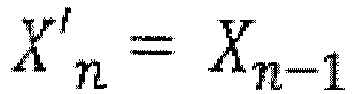
- ; when anomaly is detected, than it may become: mzres n ⁇ mzres n ⁇ 1 + 1 ⁇ ⁇ zres n , where n and n-1 denote two subsequent processing steps.
- a smoothed e.g. exponential
- ; when anomaly is detected, than it may become: mzres n ⁇ mzres n ⁇ 1 + 1 ⁇ ⁇ zres n , where n and n-1 denote two subsequent processing steps.
- the MA_DETECT flag when the residual mean mzres starts to grow and exceeds of certain threshold (possibly scaled by the squared distance X ) than the MA_DETECT flag may be issued towards the Kalman filter block 104 so that Kalman filtering may be stopped to be restarted, e.g. from a reset condition at a next movement.
- the magnetic anomaly MA_DETECT flag may be cleared once the residual mean mzres is below a captioned threshold, meaning that the anomaly has disappeared.
- the block 106 in Figure 2 is exemplary of the evaluation of certain calibration flags, such as e.g.:
- flags such as those exemplified in the foregoing may be generated in a status and control block 106a and a timeout block 106b with the time out block sending e.g. MINTIME and MAXTIME signals to the status and control block 106a.
- certain status flags are collected in 106a, such as Kalman filter fitting status, magnetic anomaly detection, steady/movement status, timeout status etc., to be read-back by a host processor.
- a calibration event may occur:
- the related processing may be executed starting from the output X (8:0) from the Kalman filter block 104.
- processing in the block 107 may involve four phases: translation, rotation, scaling and back-rotation.
- Translation processing aims at translating the center of the ellipsoid E towards the origin O of the three-dimensional coordinate system of Figure 1 .
- the purpose of rotation processing is rotating the ellipsoid E to align the ellipsoid axes with the axes of the sensing device (e.g. magnetometer M).
- the ellipsoid axes are the eigenvectors of the matrix B introduced in the foregoing.
- Scaling processing aims at scaling the ellipsoid E to a sphere S.
- Back-rotation aims at back-rotating the sphere resulting from scaling to the orientation of the ellipsoid before the rotation considered in the foregoing.
- processing as performed in the block 107 may result in the generation of a vector O and a matrix M for hard-iron offset correction and soft-iron distortion correction of the signal components.
Landscapes
- Physics & Mathematics (AREA)
- General Physics & Mathematics (AREA)
- Condensed Matter Physics & Semiconductors (AREA)
- Engineering & Computer Science (AREA)
- Radar, Positioning & Navigation (AREA)
- Remote Sensing (AREA)
- Measuring Magnetic Variables (AREA)
- Geophysics And Detection Of Objects (AREA)
Abstract
- a) translating the center (CE) of the ellipsoidal graph (E) towards the origin (O) of the three-dimensional coordinate system (X, Y, Z),
- b) rotating the ellipsoidal graph (E) to align the axes thereof with the sensing device (M) axes,
- c) scaling the ellipsoidal graph (E) to a sphere (S), and
- d) back-rotating the sphere (S) resulting from scaling to the orientation of the ellipsoidal graph (E) before rotation.
Description
- The description relates to magnetic field sensing devices.
- One or more embodiments may apply to calibration of field sensing devices such as e.g. magnetometers, compasses, sensor HUBs.
- When adequately calibrated, a magnetic field sensing device such as e.g. a magnetometer may sense the magnetic field of the earth (around 0.5 Gauss) with no additional contributions. However, local disturbances may exist in an ambient magnetic field due e.g. to nearby magnetic fields generated by electrical currents and nearby magnetic objects, such as ferrous or high permeability materials.
- These local disturbances may produce two types of distortions, known as hard-iron offsets and soft-iron distortions.
- An object of one or more embodiments is to permit both these kinds of distortions to be compensated over a wide operational range.
- One or more embodiments achieve that object thanks to an (auto)calibration method having the characteristics recited in the claims that follow.
- One or more embodiments may relate to a corresponding system and apparatus (e.g. magnetometer-based apparatus) including such a system as well as a computer program product loadable the memory of at least one processing device (e.g. a DSP) and including software code portions for executing the steps of the method when the product is run on at least one computer. As used herein, reference to such a computer program product is understood as being equivalent to reference to a computer-readable means containing instructions for controlling the processing system in order to co-ordinate implementation of the method according to one or more embodiments. Reference to "at least one processor device" is intended to highlight the possibility for one or more embodiments to be implemented in modular and/or distributed form.
- The claims are an integral part of the disclosure of one or more exemplary embodiments as provided herein.
- One or more embodiments may involve tuning of a Kalman filter coupled e.g. to a magnetometer with the ability of coping with a large range of soft iron distortions with good performance in term of fitting speed.
- Advantages offered by one or more embodiments may include:
- a wide range of hard-iron offsets and soft-iron distortions may be dealt with;
- the sample gain range can be calculated dynamically, allowing e.g. auto-scaling of parameters, which results in improved Kalman filter convergence;
- Kalman filter processing may be started and stopped according to movement detection;
- magnetic anomalies can be detected and managed.
- In one or more embodiments, Kalman filter parameter auto-scaling according to amplitude of the incoming signal may be applied to a wide variety of magnetic-field sensing applications where a Kalman filter is used.
- By relying on a geometric approach with a Kalman filter and eigenvectors, one or more embodiments may provide cost-effective solutions adapted for use in a wide range of devices.
- One or more embodiments will now be described, by way of example only, with reference to the enclosed figures, wherein:
-
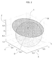
Figure 1 is generally exemplary of the effects of hard-iron offsets and soft-iron distortions in a magnetic field sensing device, and -
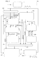
Figure 2 is a block diagram of a system according to embodiments. - In the ensuing description, one or more specific details are illustrated, aimed at providing an in-depth understanding of examples of embodiments. The embodiments may be obtained without one or more of the specific details, or with other methods, components, materials, etc. In other cases, known structures, materials, or operations are not illustrated or described in detail so that certain aspects of embodiments will not be obscured.
- Reference to "an embodiment" or "one embodiment" in the framework of the present description is intended to indicate that a particular configuration, structure, or characteristic described in relation to the embodiment is comprised in at least one embodiment. Hence, phrases such as "in an embodiment" or "in one embodiment" that may be present in one or more points of the present description do not necessarily refer to one and the same embodiment. Moreover, particular conformations, structures, or characteristics may be combined in any adequate way in one or more embodiments.
- The references used herein are provided merely for convenience and hence do not define the scope of protection or the scope of the embodiments.
- A magnetic field (e.g. the magnetic field of the earth) and its possible distortions as sensed by magnetic field sensing devices such as magnetometers may be represented by plotting the output components X , Y, Z of the sensing signal as a graph in a three-dimensional (3D) coordinate space having an origin ○ (X=0, Y= 0, Z= 0).
- Such a conventional representation is exemplified in
Figure 1 . - In the absence of local disturbance, the three components of the measurement signal correspond to a vector representative of the local magnetic field having a radius equal to the radius of a sphere S centered at the origin O of the reference coordinate system.
- As exemplified in
Figure 1 hard-iron (HI) offset effects will result in shifting the center of the 3D graph away from the origin O towards an offset center CE, without per se distorting the spherical shape of the graph. - Soft-iron distortion effects, on the other hand, will result in the spherical shape of the graph to be changed into an ellipsoidal shape E.
- An (auto)calibration process of such a magnetic field sensing device (a magnetometer will be referred to in the following for the sake of simplicity) aims at recovering - from such an ellipsoidal graph E offset from the origin O - a non-offset, non-distorted signal components corresponding to a sphere S centered at the origin O as depicted in
Figure 1 . - The foregoing may be represented as a matrix transformation as reproduced in the following:

- Xunc, Yunc, Zunc represent the un-calibrated (offset and distorted) signal components,
- Xcal, Y ca/ , Zcal represent the calibrated (non-offset and undistorted) signal components,
- O1, O2, O3 are three components representative of the offset of the center CE with respect to the origin O, and
- M11,..., M33 is a matrix representative of the geometric transformation of the ellipsoid E into a sphere S.
-
Figure 2 is a schematic representation of a block diagram of asystem 100 according to embodiments as coupled to a magnetic field sensing device such as e.g. a magnetometer M. - In the following the device M will be assumed to produce three (generally un-calibrated) signal components Xunc, Yunc, Zunc with the
system 100 having the purpose of derive therefrom corresponding (auto) calibrated signal components Xcal, Y ca/ , Zcal . - In one or more embodiments, the
system 100 may be implemented either in hardware form or in software form or as a combination of hardware and software modules. Each blocks shown inFigure 2 may thus be exemplary of hardware processing or software processing or mixed hardware/software processing. - Also, partitioning of processing among the various blocks in
Figure 2 is merely for ease of explanation insofar as one or more embodiments may adopt different arrangements e.g. by consolidating or splitting any of the blocks as shown in the Figure. - In one or more embodiments as exemplified herein, data processing (including a Kalman filtering as better detailed in the following) of the signal components X , Y, Z (unless specified otherwise, in the following the suffixes " unc " and " cal " distinguishing un-calibrated and calibrated components will be dropped for brevity) may be performed after a movement detection, that is after the sensing device (magnetometer) M is subject to movement.
- In one or more embodiments, a
movement detector block 101 may include a filter such as a derivative filter to apply filtering (e.g. of a finite impulse response - FIR type) to each component X, Y, Z possibly followed by an exponential smoothed average of the absolute value. - In one or more embodiments, the
movement detector block 101 may include a double threshold comparator. - In one or more embodiments, the signal components X, Y, Z may be checked against upper (e.g. absolute value) thresholds, so that these upper absolute value thresholds being reached will be indicative of movement being started.
- For instance, in order to assert that movement is starting, all the three average signal derivatives abs (mdmagXYZ) may be checked to be above a start threshold.
- Likewise, in one or more embodiments, the signal components X, Y, Z may be checked against lower (e.g. absolute value) thresholds, so that these lower absolute value thresholds being reached will be indicative of movement being discontinued (e.g. stopped).
- In that way, a movement may be asserted to be completed and the sensing device (magnetometer M) held to be still (stationary) when the three signals in question are below a stop threshold.
- In one or more embodiments, such start (upper) and stop (lower) thresholds may be computed by multiplying programmed values by individual factors indicative of a distance (which may be possibly different for each component mdmagXYZ ) as possibly computed in a MIN-
MAX distance block 103 to be described in the following. - In one or more embodiments, the
movement detector block 101 may thus act like a sort of auto-scaling function of the thresholds according to the incoming data range thus allowing to deal automatically with e.g. large soft-iron distortion. - In one or more embodiments as exemplified in
Figure 2 , the signal components Xunc , Yunc , Zunc may also be fed to anoffset removal block 102. - Signal components as possibly produced by a magnetometer M may be affected by offsets of tens of Gauss units, e.g. 50-60 times larger than the useful signal due to hard-iron distortion.
- In one or more embodiments, the values of the signal components (samples) at the beginning of movement (as detected e.g. in the block 101) may be stored and subtracted to the subsequently incoming samples to be eventually restored at the end of calibration, e.g. by being added to the computed center.
- In one or more embodiments, processing as performed in various blocks considered in the following may be performed on offset-scaled signal components (samples) mg'XYZ scaled e.g. by a scaling value scale_offXYZ as stored upon movement of the sensing device M being detected, e.g. mag'XYZ = magXYZ- scale_offXYZ, where magXYZ denotes, in compact form, input samples Xunc, Yunc, Zunc affected by offset.
- In one or more embodiments, the MIN-MAX
distance block 103 already mentioned in the foregoing may take into account the fact that the signal components X, Y, Z as produced by the device M may be effected by a wide range of soft-iron distortion, with the incoming signal range being generally unknown a priori. - In one or more embodiments, e.g. in order to better tune the Kalman
filtering block 104 to be discussed in the following, the gain of the incoming signal may be estimated in theblock 103. - In one or more embodiments, the maximum and minimum values of the signal components (samples) maxXYZ and minXYZ, respectively may be stored e.g. upon their arrival, individually for each of the three components X, Y, Z, by possibly defining the distance for each component X, Y, Z e.g. as:

- In one or more embodiments, possibly after offset removal in
block 102 and MIN-MAX distance evaluation inblock 103, the input signal components (samples) may be fed to aKalman filter block 104 along with an enable signal KF_GO. - In one or more embodiments, the purpose of such a filter is to yield a set of e.g. nine parameters that fit an ellipsoid shape (e.g. E in
Figure 1 ). - The quadratic form of an ellipsoid is:


- By denoting as m1, m2, m3 the X, Y, Z sample values:


- predicting values


- correcting values


- The diagonal matrix Q and the scalar R are respectively the process and output noise covariance.
- Adequate filter performance in terms of fitting speed may be reached by scaling the output noise covariance according to the computed distanceXYZ , such as R = Ro * median ( distanceXYZ ) ^4.
- The e.g. nine ellipsoid parameters thus computed may be denoted X (8:0).
- In one or more embodiments, a magnetic
anomaly detector block 105 may be provided. - In one or more embodiments, operation of such a
block 105 may assume that theKalman filter 104 has a fit, meaning that the data provided by the magnetic field sensing device (e.g. magnetometer M) belong to an ellipsoid. - In one or more embodiments, the
block 105 may receive from theblock 104 the Kalman residual zres, that is the difference between the predicted system output and the real samples assumes an abnormal value. - In one or more embodiments, operation of the
block 105 may involve checking if the difference between the output signal as predicted by Kalman filter processing and the current magnetometer output signal reaches an anomaly threshold. - If the difference in question reaches the anomaly threshold (see e.g. the flag MA DETECT in
Figure 2 ) Kalman filter processing in theblock 104 may be discontinued to be resumed e.g. at a subsequent movement of the device (magnetometer M), optionally from a reset condition. - In one or more embodiments, managing the zres behavior may involve computing a smoothed (e.g. exponential) mean or average, peak-detector like: when no anomaly is detected, the average value may assume the value of | zres |; when anomaly is detected, than it may become:

- In one or more embodiments, when the residual mean mzres starts to grow and exceeds of certain threshold (possibly scaled by the squared distanceX ) than the MA_DETECT flag may be issued towards the
Kalman filter block 104 so that Kalman filtering may be stopped to be restarted, e.g. from a reset condition at a next movement. - In one or more embodiments the magnetic anomaly MA_DETECT flag may be cleared once the residual mean mzres is below a captioned threshold, meaning that the anomaly has disappeared.
- The
block 106 inFigure 2 is exemplary of the evaluation of certain calibration flags, such as e.g.: - the
Kalman filter 104 has to fit the ellipsoid shape E, - three delay counters have reached a programmed value, meaning that each component distance distanceXYZ has exceeded a programmable lowest distance for a given number of samples,
- a minimum time has elapsed between two subsequent calibration procedures,
- the system is in a steady condition, meaning that a movement has been completed.
- In one or more embodiments, flags such as those exemplified in the foregoing may be generated in a status and
control block 106a and atimeout block 106b with the time out block sending e.g. MINTIME and MAXTIME signals to the status andcontrol block 106a. - In one or more embodiments, certain status flags are collected in 106a, such as Kalman filter fitting status, magnetic anomaly detection, steady/movement status, timeout status etc., to be read-back by a host processor. In one or more embodiments, a calibration event may occur:
- not before a MINTIME number of samples from a previous calibration event, and
- not after a MAXTIME number of samples from a previous calibration event or from the procedure start.
- If a MAXTIME number of samples are exceeded without a calibration event, then the Kalman filter is reset and the overall process is restarted.
- When the conditions expressed by the flags above are checked to be verified in the
block 106, operation of ablock 107 for a matrix and center calculation may be enabled. - In one or more embodiments, the related processing may be executed starting from the output X (8:0) from the
Kalman filter block 104. - In one or more embodiments, processing in the
block 107 may involve four phases: translation, rotation, scaling and back-rotation. - Translation processing aims at translating the center of the ellipsoid E towards the origin O of the three-dimensional coordinate system of
Figure 1 . - In one or more embodiments, this may involve solving a system of linear equations in order to obtain the center coordinates:

- In one or more embodiments, translation to the center may involve a variable substitution such as:

- In one or more embodiments, the purpose of rotation processing is rotating the ellipsoid E to align the ellipsoid axes with the axes of the sensing device (e.g. magnetometer M).
- The ellipsoid axes are the eigenvectors of the matrix B introduced in the foregoing.
- Rotation may be based on a matrix V including the resulting eigenvectors to perform the rotation:

- The foregoing results in having an ellipsoid which is both centered at the origin O and with its axes aligned with the axes of the sensing device.
- Its quadratic form will be:


- Scaling processing aims at scaling the ellipsoid E to a sphere S.
- The ellipsoid semi-axes may be represented as


- To sum up:

- Back-rotation aims at back-rotating the sphere resulting from scaling to the orientation of the ellipsoid before the rotation considered in the foregoing.
- In one or more embodiments, back-rotation may be involve multiplication for the matrix V:


- The foregoing results in a centered sphere S having a radius LMF without any additional rotation.
- In one or more embodiments, processing as performed in the
block 107 may result in the generation of a vector O and a matrix M for hard-iron offset correction and soft-iron distortion correction of the signal components. - In one or more embodiments this may take the form of an offset vector [x0 y0 z0] and a gain matrix M = V * scale* V T .
- In a
sample calibration block 108 the offset stored at the beginning of processing (as a result of processing performed in block 102) may be restored and added to the ellipsoid center to yield a final hard-iron offset correction in the form
- Finally, in one or more embodiments, the calibrated samples at the output of the
block 108 may be obtained as:
- Without prejudice to the underlying principles, the details and embodiments may vary, even significantly, with respect to what has been described by way of example only without departing from the extent of protection.
- The extent of protection is defined by the annexed claims.
Claims (10)
- A method of calibrating a magnetic field sensing device (M), wherein calibrated sensing signal components ( Xcal, Ycal, Zcal ) represented in a three-dimensional coordinate system (X, Y, Z) by a spherical graph (S) centered at the origin (O) of said three-dimensional coordinate system (X, Y, Z) are generated from uncalibrated signal components ( Xunc, Yunc, Zunc ) from said magnetic field sensing device (M) represented in said three-dimensional coordinate system (X, Y, Z) by an ellipsoidal graph (E) having a center (CE) offset with respect to the origin (O) of said three-dimensional coordinate system (X, Y, Z),
wherein the method includes applying to said sensing signal components Kalman filter processing (104) yielding a set of parameters (X(8:0)) fitting said ellipsoidal graph (E) by prediction and correction based on said prediction. - The method of claim 1, including processing (107) said set of parameters (X(8:0)) fitting said ellipsoidal graph (E) obtained from Kalman filter processing (104) by:- a) translating the center (CE) of said ellipsoidal graph (E) towards the origin (O) of said three-dimensional coordinate system (X, Y, Z),- b) rotating said ellipsoidal graph (E) to align the axes thereof with the sensing device (M) axes,- c) scaling the ellipsoidal graph (E) to a sphere (S), and- d) back-rotating the sphere (S) resulting from scaling to the orientation of said ellipsoidal graph (E) before said rotation under b).
- The method of claim 1 or claim 2, wherein, with said ellipsoidal graph (E) expressed in quadratic form as:


 - predicting values

 - correcting values


- The method of any of claims 1 to 3, including (101) :- applying to said sensing signal components at least one of filtering, preferably derivative filtering of the FIR type, and averaging, preferably exponential smoothed averaging, and/or- checking said sensing signal components against upper value thresholds, said upper value thresholds being reached being indicative of movement of the magnetic field sensing device (M) being started, and/or- checking said sensing signal components against lower value thresholds, said absolute value thresholds being reached being indicative of movement of the magnetic field sensing device (M) being stopped, and/or- performing said Kalman filter processing (104) conditional to detecting movement of the magnetic field sensing device (M).
- The method of any of the previous claims, including (102):- detecting movement of the magnetic field sensing device (M),- storing the values of said sensing signal components from the magnetic field sensing device (M) upon detecting movement of the magnetic field sensing device (M), and- subtracting the values stored from said sensing signal components forwarded to said Kalman filter processing (104), preferably restoring (107) said stored values in the calibrated sensing signal components ( Xcal , Ycal , Zcal ).
- The method of any of the previous claims, including estimating (103) the gain of said sensing signal components forwarded to said Kalman filter processing (104), preferably as difference of maximum and minimum values of said sensing signal components.
- The method of any of the previous claims, including (105):- checking if the difference between the sensing signal components as predicted in Kalman filter processing (104) and the current sensing signal components reaches an anomaly threshold,- if said difference reaches said anomaly threshold, discontinuing Kalman filter processing (104) and resuming Kalman filter processing (104) at a subsequent sensing movement, preferably from a rest condition.
- A system for calibrating a magnetic field sensing device (M), wherein calibrated sensing signal components ( Xcal , Ycal , Zcal ) represented in a three-dimensional coordinate system (X, Y, Z) by a spherical graph (S) centered at the origin (O) of said three-dimensional coordinate system (X, Y, Z) are generated from uncalibrated signal components ( Xunc , Yunc , Zunc ) from said magnetic field sensing device (M) represented in said three-dimensional coordinate system (X, Y, Z) by an ellipsoidal graph (E) having a center (CE) offset with respect to the origin (O) of said three-dimensional coordinate system (X, Y, Z),
wherein the system includes a Kalman filter module (104) for applying to said sensing signal components Kalman filter processing yielding a set of parameters (X(8:0)) fitting said ellipsoidal graph (E) by prediction and correction based on said prediction, the system configures to implement the method of any of claims 1 to 7. - Apparatus including:- a magnetic field sensing device, preferably a magnetometer (M), and- a calibration system (100) according to claim 8 coupled to said magnetic field sensing device (M) to calibrate uncalibrated magnetic field sensing signal components ( Xunc , Yunc , Zunc ) from said magnetic field sensing device (M).
- A computer program product loadable in the memory of at least one digital processor device and including software code portions for executing the steps of the method of any of claims 1 to 7 when the product is run on at least one processor device.
Applications Claiming Priority (1)
| Application Number | Priority Date | Filing Date | Title |
|---|---|---|---|
| ITUB2015A003317A ITUB20153317A1 (en) | 2015-09-01 | 2015-09-01 | CALIBRATION PROCEDURE FOR DEVICES MAGNETIC FIELD SENSORS, SYSTEM, EQUIPMENT AND CORRESPONDENT COMPUTER PRODUCT |
Publications (2)
| Publication Number | Publication Date |
|---|---|
| EP3139128A1 true EP3139128A1 (en) | 2017-03-08 |
| EP3139128B1 EP3139128B1 (en) | 2019-05-01 |
Family
ID=54542464
Family Applications (1)
| Application Number | Title | Priority Date | Filing Date |
|---|---|---|---|
| EP16161413.6A Active EP3139128B1 (en) | 2015-09-01 | 2016-03-21 | A calibration method for magnetic field sensing devices, corresponding system, apparatus and computer program product |
Country Status (4)
| Country | Link |
|---|---|
| US (1) | US10379173B2 (en) |
| EP (1) | EP3139128B1 (en) |
| CN (1) | CN106483475B (en) |
| IT (1) | ITUB20153317A1 (en) |
Cited By (1)
| Publication number | Priority date | Publication date | Assignee | Title |
|---|---|---|---|---|
| CN109059960A (en) * | 2018-07-18 | 2018-12-21 | 福州大学 | A kind of calibration method of three-dimensional electronic compass |
Families Citing this family (7)
| Publication number | Priority date | Publication date | Assignee | Title |
|---|---|---|---|---|
| CN107607888B (en) * | 2017-10-12 | 2020-06-09 | 国家电网公司 | A three-dimensional transient magnetic field measurement system |
| CN107907142B (en) * | 2017-10-12 | 2020-09-11 | 歌尔科技有限公司 | Initial calibration method and device for magnetometer and magnetometer |
| DE102019121392A1 (en) * | 2019-08-08 | 2021-02-11 | Infineon Technologies Ag | DEVICE AND METHOD FOR CALIBRATING AN ANGLE SENSOR |
| US11815568B2 (en) | 2020-12-28 | 2023-11-14 | Stmicroelectronics, Inc. | System and method for fast magnetometer calibration using gyroscope |
| CN118176430A (en) * | 2021-10-11 | 2024-06-11 | 国家医疗保健研究所 | Devices and systems for measuring magnetic fields |
| CN114264997B (en) * | 2021-12-14 | 2024-03-22 | 武汉联影生命科学仪器有限公司 | Gradient sensitivity calibration method and device and magnetic resonance equipment |
| CN117879540B (en) * | 2024-03-12 | 2024-06-18 | 西南应用磁学研究所(中国电子科技集团公司第九研究所) | Magnetic compass sensor self-adaptive signal filtering method based on improved Kalman filtering |
Citations (2)
| Publication number | Priority date | Publication date | Assignee | Title |
|---|---|---|---|---|
| US20150177020A1 (en) * | 2012-08-02 | 2015-06-25 | Memsic, Inc. | Method and apparatus for data fusion of a three-axis magnetometer and three axis accelerometer |
| US20150241390A1 (en) * | 2014-02-23 | 2015-08-27 | PNI Sensor Corporation | Automatically updating hard iron and soft iron coefficients of a magnetic sensor |
Family Cites Families (6)
| Publication number | Priority date | Publication date | Assignee | Title |
|---|---|---|---|---|
| ATE511128T1 (en) * | 2005-04-04 | 2011-06-15 | Fisher Rosemount Systems Inc | STATISTICAL PROCESSING METHODS FOR DETECTING ANORMAL SITUATIONS |
| US7930148B1 (en) * | 2007-08-20 | 2011-04-19 | PNI Sensor Corporation | Spherical calibration and reference alignment algorithms |
| US7977941B2 (en) | 2009-02-25 | 2011-07-12 | Everspin Technologies, Inc. | Magnetic field sensing device |
| DE102010029668A1 (en) | 2010-06-02 | 2011-12-08 | Robert Bosch Gmbh | Calibration of a three-axis magnetic field sensor |
| DE102010029669B4 (en) * | 2010-06-02 | 2023-10-05 | Robert Bosch Gmbh | Method for adjusting a measured value offset |
| US8717009B2 (en) * | 2010-10-06 | 2014-05-06 | Apple Inc. | Magnetometer calibration |
-
2015
- 2015-09-01 IT ITUB2015A003317A patent/ITUB20153317A1/en unknown
-
2016
- 2016-03-21 EP EP16161413.6A patent/EP3139128B1/en active Active
- 2016-03-21 US US15/076,225 patent/US10379173B2/en active Active
- 2016-03-30 CN CN201610195569.7A patent/CN106483475B/en active Active
Patent Citations (2)
| Publication number | Priority date | Publication date | Assignee | Title |
|---|---|---|---|---|
| US20150177020A1 (en) * | 2012-08-02 | 2015-06-25 | Memsic, Inc. | Method and apparatus for data fusion of a three-axis magnetometer and three axis accelerometer |
| US20150241390A1 (en) * | 2014-02-23 | 2015-08-27 | PNI Sensor Corporation | Automatically updating hard iron and soft iron coefficients of a magnetic sensor |
Cited By (2)
| Publication number | Priority date | Publication date | Assignee | Title |
|---|---|---|---|---|
| CN109059960A (en) * | 2018-07-18 | 2018-12-21 | 福州大学 | A kind of calibration method of three-dimensional electronic compass |
| CN109059960B (en) * | 2018-07-18 | 2021-08-31 | 福州大学 | A kind of calibration method of three-dimensional electronic compass |
Also Published As
| Publication number | Publication date |
|---|---|
| ITUB20153317A1 (en) | 2017-03-01 |
| CN106483475B (en) | 2020-06-05 |
| US10379173B2 (en) | 2019-08-13 |
| EP3139128B1 (en) | 2019-05-01 |
| US20170059667A1 (en) | 2017-03-02 |
| CN106483475A (en) | 2017-03-08 |
Similar Documents
| Publication | Publication Date | Title |
|---|---|---|
| EP3139128B1 (en) | A calibration method for magnetic field sensing devices, corresponding system, apparatus and computer program product | |
| US11435425B2 (en) | IMU calibration | |
| KR101783050B1 (en) | Method and device for calibrating a three-axis magnetic field sensor | |
| CN103153790B (en) | The measurement data of the magnetometer using motion sensor and be attached to device estimates equipment and the method for this device yaw angle in gravitational frame of reference | |
| US11480422B2 (en) | Method for estimating an angular deviation between the magnetic axis and a reference axis of a magnetic object | |
| Mirzaei et al. | Globally optimal pose estimation from line correspondences | |
| US4321681A (en) | Protective relay apparatus | |
| CN108426571B (en) | Local real-time calibration method and device for electronic compass | |
| US20130088239A1 (en) | Fault-type identification for electric power delivery systems | |
| JP2008076397A (en) | Compass sensor calibration method, apparatus and medium in consideration of magnetic environment, and azimuth measuring method, apparatus and medium using the same | |
| CN110998569B (en) | Method for estimating the position of a magnet including a stage of identifying magnetic disturbances | |
| CA3078092C (en) | Method for operating a metal detector and metal detector | |
| US7292948B2 (en) | Magnetic position and orientation measurement system with eddy current distortion compensation | |
| Jose et al. | Performance study of edge detection operators | |
| JP2012522210A (en) | Apparatus and method for ferromagnetic object detector | |
| Wan et al. | Single frame infrared small target detection based on local gradient and directional curvature | |
| Liu et al. | Blind correction of the EB-leakage in the pixel domain | |
| EP1159639B1 (en) | High fidelity rotation method and system for seismic data | |
| Guo | A simple algorithm for fitting a Gaussian function | |
| US5798932A (en) | Methods and apparatus for removing error due to decaying offsets from measured power system currents | |
| Ge et al. | Suppression of the negative effect of abnormal data based on the Hough transform and application to the magnetic compensation of airborne optically-pumped magnetometer data | |
| Deokar | Implementation of Canny Edge Detector Algorithm using FPGA | |
| US20160011283A1 (en) | Accelerating first order reversal curve distribution measurments | |
| KR20170061750A (en) | Partial discharge measuring device | |
| Alkhatib et al. | Robust multivariate time series analysis in nonlinear models with autoregressive and t-distributed errors |
Legal Events
| Date | Code | Title | Description |
|---|---|---|---|
| PUAI | Public reference made under article 153(3) epc to a published international application that has entered the european phase |
Free format text: ORIGINAL CODE: 0009012 |
|
| STAA | Information on the status of an ep patent application or granted ep patent |
Free format text: STATUS: THE APPLICATION HAS BEEN PUBLISHED |
|
| AK | Designated contracting states |
Kind code of ref document: A1 Designated state(s): AL AT BE BG CH CY CZ DE DK EE ES FI FR GB GR HR HU IE IS IT LI LT LU LV MC MK MT NL NO PL PT RO RS SE SI SK SM TR |
|
| AX | Request for extension of the european patent |
Extension state: BA ME |
|
| STAA | Information on the status of an ep patent application or granted ep patent |
Free format text: STATUS: REQUEST FOR EXAMINATION WAS MADE |
|
| 17P | Request for examination filed |
Effective date: 20170905 |
|
| RBV | Designated contracting states (corrected) |
Designated state(s): AL AT BE BG CH CY CZ DE DK EE ES FI FR GB GR HR HU IE IS IT LI LT LU LV MC MK MT NL NO PL PT RO RS SE SI SK SM TR |
|
| GRAP | Despatch of communication of intention to grant a patent |
Free format text: ORIGINAL CODE: EPIDOSNIGR1 |
|
| STAA | Information on the status of an ep patent application or granted ep patent |
Free format text: STATUS: GRANT OF PATENT IS INTENDED |
|
| INTG | Intention to grant announced |
Effective date: 20181114 |
|
| GRAS | Grant fee paid |
Free format text: ORIGINAL CODE: EPIDOSNIGR3 |
|
| GRAA | (expected) grant |
Free format text: ORIGINAL CODE: 0009210 |
|
| STAA | Information on the status of an ep patent application or granted ep patent |
Free format text: STATUS: THE PATENT HAS BEEN GRANTED |
|
| AK | Designated contracting states |
Kind code of ref document: B1 Designated state(s): AL AT BE BG CH CY CZ DE DK EE ES FI FR GB GR HR HU IE IS IT LI LT LU LV MC MK MT NL NO PL PT RO RS SE SI SK SM TR |
|
| REG | Reference to a national code |
Ref country code: GB Ref legal event code: FG4D |
|
| REG | Reference to a national code |
Ref country code: CH Ref legal event code: EP Ref country code: AT Ref legal event code: REF Ref document number: 1127539 Country of ref document: AT Kind code of ref document: T Effective date: 20190515 |
|
| REG | Reference to a national code |
Ref country code: DE Ref legal event code: R096 Ref document number: 602016013038 Country of ref document: DE |
|
| REG | Reference to a national code |
Ref country code: IE Ref legal event code: FG4D |
|
| REG | Reference to a national code |
Ref country code: NL Ref legal event code: MP Effective date: 20190501 |
|
| REG | Reference to a national code |
Ref country code: LT Ref legal event code: MG4D |
|
| PG25 | Lapsed in a contracting state [announced via postgrant information from national office to epo] |
Ref country code: AL Free format text: LAPSE BECAUSE OF FAILURE TO SUBMIT A TRANSLATION OF THE DESCRIPTION OR TO PAY THE FEE WITHIN THE PRESCRIBED TIME-LIMIT Effective date: 20190501 Ref country code: PT Free format text: LAPSE BECAUSE OF FAILURE TO SUBMIT A TRANSLATION OF THE DESCRIPTION OR TO PAY THE FEE WITHIN THE PRESCRIBED TIME-LIMIT Effective date: 20190901 Ref country code: SE Free format text: LAPSE BECAUSE OF FAILURE TO SUBMIT A TRANSLATION OF THE DESCRIPTION OR TO PAY THE FEE WITHIN THE PRESCRIBED TIME-LIMIT Effective date: 20190501 Ref country code: FI Free format text: LAPSE BECAUSE OF FAILURE TO SUBMIT A TRANSLATION OF THE DESCRIPTION OR TO PAY THE FEE WITHIN THE PRESCRIBED TIME-LIMIT Effective date: 20190501 Ref country code: NO Free format text: LAPSE BECAUSE OF FAILURE TO SUBMIT A TRANSLATION OF THE DESCRIPTION OR TO PAY THE FEE WITHIN THE PRESCRIBED TIME-LIMIT Effective date: 20190801 Ref country code: HR Free format text: LAPSE BECAUSE OF FAILURE TO SUBMIT A TRANSLATION OF THE DESCRIPTION OR TO PAY THE FEE WITHIN THE PRESCRIBED TIME-LIMIT Effective date: 20190501 Ref country code: NL Free format text: LAPSE BECAUSE OF FAILURE TO SUBMIT A TRANSLATION OF THE DESCRIPTION OR TO PAY THE FEE WITHIN THE PRESCRIBED TIME-LIMIT Effective date: 20190501 Ref country code: LT Free format text: LAPSE BECAUSE OF FAILURE TO SUBMIT A TRANSLATION OF THE DESCRIPTION OR TO PAY THE FEE WITHIN THE PRESCRIBED TIME-LIMIT Effective date: 20190501 Ref country code: ES Free format text: LAPSE BECAUSE OF FAILURE TO SUBMIT A TRANSLATION OF THE DESCRIPTION OR TO PAY THE FEE WITHIN THE PRESCRIBED TIME-LIMIT Effective date: 20190501 |
|
| PG25 | Lapsed in a contracting state [announced via postgrant information from national office to epo] |
Ref country code: RS Free format text: LAPSE BECAUSE OF FAILURE TO SUBMIT A TRANSLATION OF THE DESCRIPTION OR TO PAY THE FEE WITHIN THE PRESCRIBED TIME-LIMIT Effective date: 20190501 Ref country code: BG Free format text: LAPSE BECAUSE OF FAILURE TO SUBMIT A TRANSLATION OF THE DESCRIPTION OR TO PAY THE FEE WITHIN THE PRESCRIBED TIME-LIMIT Effective date: 20190801 Ref country code: LV Free format text: LAPSE BECAUSE OF FAILURE TO SUBMIT A TRANSLATION OF THE DESCRIPTION OR TO PAY THE FEE WITHIN THE PRESCRIBED TIME-LIMIT Effective date: 20190501 Ref country code: GR Free format text: LAPSE BECAUSE OF FAILURE TO SUBMIT A TRANSLATION OF THE DESCRIPTION OR TO PAY THE FEE WITHIN THE PRESCRIBED TIME-LIMIT Effective date: 20190802 |
|
| REG | Reference to a national code |
Ref country code: AT Ref legal event code: MK05 Ref document number: 1127539 Country of ref document: AT Kind code of ref document: T Effective date: 20190501 |
|
| PG25 | Lapsed in a contracting state [announced via postgrant information from national office to epo] |
Ref country code: IS Free format text: LAPSE BECAUSE OF FAILURE TO SUBMIT A TRANSLATION OF THE DESCRIPTION OR TO PAY THE FEE WITHIN THE PRESCRIBED TIME-LIMIT Effective date: 20190901 |
|
| PG25 | Lapsed in a contracting state [announced via postgrant information from national office to epo] |
Ref country code: DK Free format text: LAPSE BECAUSE OF FAILURE TO SUBMIT A TRANSLATION OF THE DESCRIPTION OR TO PAY THE FEE WITHIN THE PRESCRIBED TIME-LIMIT Effective date: 20190501 Ref country code: EE Free format text: LAPSE BECAUSE OF FAILURE TO SUBMIT A TRANSLATION OF THE DESCRIPTION OR TO PAY THE FEE WITHIN THE PRESCRIBED TIME-LIMIT Effective date: 20190501 Ref country code: AT Free format text: LAPSE BECAUSE OF FAILURE TO SUBMIT A TRANSLATION OF THE DESCRIPTION OR TO PAY THE FEE WITHIN THE PRESCRIBED TIME-LIMIT Effective date: 20190501 Ref country code: RO Free format text: LAPSE BECAUSE OF FAILURE TO SUBMIT A TRANSLATION OF THE DESCRIPTION OR TO PAY THE FEE WITHIN THE PRESCRIBED TIME-LIMIT Effective date: 20190501 Ref country code: SK Free format text: LAPSE BECAUSE OF FAILURE TO SUBMIT A TRANSLATION OF THE DESCRIPTION OR TO PAY THE FEE WITHIN THE PRESCRIBED TIME-LIMIT Effective date: 20190501 Ref country code: CZ Free format text: LAPSE BECAUSE OF FAILURE TO SUBMIT A TRANSLATION OF THE DESCRIPTION OR TO PAY THE FEE WITHIN THE PRESCRIBED TIME-LIMIT Effective date: 20190501 |
|
| REG | Reference to a national code |
Ref country code: DE Ref legal event code: R097 Ref document number: 602016013038 Country of ref document: DE |
|
| PG25 | Lapsed in a contracting state [announced via postgrant information from national office to epo] |
Ref country code: IT Free format text: LAPSE BECAUSE OF FAILURE TO SUBMIT A TRANSLATION OF THE DESCRIPTION OR TO PAY THE FEE WITHIN THE PRESCRIBED TIME-LIMIT Effective date: 20190501 Ref country code: SM Free format text: LAPSE BECAUSE OF FAILURE TO SUBMIT A TRANSLATION OF THE DESCRIPTION OR TO PAY THE FEE WITHIN THE PRESCRIBED TIME-LIMIT Effective date: 20190501 |
|
| PLBE | No opposition filed within time limit |
Free format text: ORIGINAL CODE: 0009261 |
|
| STAA | Information on the status of an ep patent application or granted ep patent |
Free format text: STATUS: NO OPPOSITION FILED WITHIN TIME LIMIT |
|
| PG25 | Lapsed in a contracting state [announced via postgrant information from national office to epo] |
Ref country code: TR Free format text: LAPSE BECAUSE OF FAILURE TO SUBMIT A TRANSLATION OF THE DESCRIPTION OR TO PAY THE FEE WITHIN THE PRESCRIBED TIME-LIMIT Effective date: 20190501 |
|
| 26N | No opposition filed |
Effective date: 20200204 |
|
| PG25 | Lapsed in a contracting state [announced via postgrant information from national office to epo] |
Ref country code: PL Free format text: LAPSE BECAUSE OF FAILURE TO SUBMIT A TRANSLATION OF THE DESCRIPTION OR TO PAY THE FEE WITHIN THE PRESCRIBED TIME-LIMIT Effective date: 20190501 |
|
| PG25 | Lapsed in a contracting state [announced via postgrant information from national office to epo] |
Ref country code: SI Free format text: LAPSE BECAUSE OF FAILURE TO SUBMIT A TRANSLATION OF THE DESCRIPTION OR TO PAY THE FEE WITHIN THE PRESCRIBED TIME-LIMIT Effective date: 20190501 |
|
| PG25 | Lapsed in a contracting state [announced via postgrant information from national office to epo] |
Ref country code: MC Free format text: LAPSE BECAUSE OF FAILURE TO SUBMIT A TRANSLATION OF THE DESCRIPTION OR TO PAY THE FEE WITHIN THE PRESCRIBED TIME-LIMIT Effective date: 20190501 |
|
| REG | Reference to a national code |
Ref country code: CH Ref legal event code: PL |
|
| REG | Reference to a national code |
Ref country code: BE Ref legal event code: MM Effective date: 20200331 |
|
| PG25 | Lapsed in a contracting state [announced via postgrant information from national office to epo] |
Ref country code: LU Free format text: LAPSE BECAUSE OF NON-PAYMENT OF DUE FEES Effective date: 20200321 |
|
| PG25 | Lapsed in a contracting state [announced via postgrant information from national office to epo] |
Ref country code: CH Free format text: LAPSE BECAUSE OF NON-PAYMENT OF DUE FEES Effective date: 20200331 Ref country code: LI Free format text: LAPSE BECAUSE OF NON-PAYMENT OF DUE FEES Effective date: 20200331 Ref country code: FR Free format text: LAPSE BECAUSE OF NON-PAYMENT OF DUE FEES Effective date: 20200331 Ref country code: IE Free format text: LAPSE BECAUSE OF NON-PAYMENT OF DUE FEES Effective date: 20200321 |
|
| PG25 | Lapsed in a contracting state [announced via postgrant information from national office to epo] |
Ref country code: BE Free format text: LAPSE BECAUSE OF NON-PAYMENT OF DUE FEES Effective date: 20200331 |
|
| GBPC | Gb: european patent ceased through non-payment of renewal fee |
Effective date: 20200321 |
|
| PG25 | Lapsed in a contracting state [announced via postgrant information from national office to epo] |
Ref country code: GB Free format text: LAPSE BECAUSE OF NON-PAYMENT OF DUE FEES Effective date: 20200321 |
|
| PG25 | Lapsed in a contracting state [announced via postgrant information from national office to epo] |
Ref country code: MT Free format text: LAPSE BECAUSE OF FAILURE TO SUBMIT A TRANSLATION OF THE DESCRIPTION OR TO PAY THE FEE WITHIN THE PRESCRIBED TIME-LIMIT Effective date: 20190501 Ref country code: CY Free format text: LAPSE BECAUSE OF FAILURE TO SUBMIT A TRANSLATION OF THE DESCRIPTION OR TO PAY THE FEE WITHIN THE PRESCRIBED TIME-LIMIT Effective date: 20190501 |
|
| PG25 | Lapsed in a contracting state [announced via postgrant information from national office to epo] |
Ref country code: MK Free format text: LAPSE BECAUSE OF FAILURE TO SUBMIT A TRANSLATION OF THE DESCRIPTION OR TO PAY THE FEE WITHIN THE PRESCRIBED TIME-LIMIT Effective date: 20190501 |
|
| PGFP | Annual fee paid to national office [announced via postgrant information from national office to epo] |
Ref country code: DE Payment date: 20260219 Year of fee payment: 11 |