EP3138724A1 - Method to control an electric motor with adjustment of the value of the equivalent impedance - Google Patents
Method to control an electric motor with adjustment of the value of the equivalent impedance Download PDFInfo
- Publication number
- EP3138724A1 EP3138724A1 EP16187080.3A EP16187080A EP3138724A1 EP 3138724 A1 EP3138724 A1 EP 3138724A1 EP 16187080 A EP16187080 A EP 16187080A EP 3138724 A1 EP3138724 A1 EP 3138724A1
- Authority
- EP
- European Patent Office
- Prior art keywords
- torque
- electric motor
- rls
- offset
- speed
- Prior art date
- Legal status (The legal status is an assumption and is not a legal conclusion. Google has not performed a legal analysis and makes no representation as to the accuracy of the status listed.)
- Granted
Links
- 238000000034 method Methods 0.000 title claims abstract description 30
- 230000005540 biological transmission Effects 0.000 claims description 22
- 230000007423 decrease Effects 0.000 claims description 7
- 239000000314 lubricant Substances 0.000 claims description 5
- 238000002485 combustion reaction Methods 0.000 claims description 4
- 238000004364 calculation method Methods 0.000 description 21
- 230000033001 locomotion Effects 0.000 description 9
- 238000005461 lubrication Methods 0.000 description 8
- 239000006185 dispersion Substances 0.000 description 7
- 230000000694 effects Effects 0.000 description 5
- 238000010276 construction Methods 0.000 description 4
- 230000009977 dual effect Effects 0.000 description 4
- 230000006870 function Effects 0.000 description 4
- 238000003860 storage Methods 0.000 description 3
- 239000012190 activator Substances 0.000 description 2
- 238000001816 cooling Methods 0.000 description 2
- 238000010586 diagram Methods 0.000 description 2
- 238000013178 mathematical model Methods 0.000 description 2
- 230000002441 reversible effect Effects 0.000 description 2
- 238000009825 accumulation Methods 0.000 description 1
- 239000003990 capacitor Substances 0.000 description 1
- 230000005611 electricity Effects 0.000 description 1
- 230000002349 favourable effect Effects 0.000 description 1
- 238000004519 manufacturing process Methods 0.000 description 1
- 238000005259 measurement Methods 0.000 description 1
- 239000000126 substance Substances 0.000 description 1
- 238000011144 upstream manufacturing Methods 0.000 description 1
Images

Classifications
-
- B—PERFORMING OPERATIONS; TRANSPORTING
- B60—VEHICLES IN GENERAL
- B60L—PROPULSION OF ELECTRICALLY-PROPELLED VEHICLES; SUPPLYING ELECTRIC POWER FOR AUXILIARY EQUIPMENT OF ELECTRICALLY-PROPELLED VEHICLES; ELECTRODYNAMIC BRAKE SYSTEMS FOR VEHICLES IN GENERAL; MAGNETIC SUSPENSION OR LEVITATION FOR VEHICLES; MONITORING OPERATING VARIABLES OF ELECTRICALLY-PROPELLED VEHICLES; ELECTRIC SAFETY DEVICES FOR ELECTRICALLY-PROPELLED VEHICLES
- B60L1/00—Supplying electric power to auxiliary equipment of vehicles
- B60L1/003—Supplying electric power to auxiliary equipment of vehicles to auxiliary motors, e.g. for pumps, compressors
-
- B—PERFORMING OPERATIONS; TRANSPORTING
- B60—VEHICLES IN GENERAL
- B60W—CONJOINT CONTROL OF VEHICLE SUB-UNITS OF DIFFERENT TYPE OR DIFFERENT FUNCTION; CONTROL SYSTEMS SPECIALLY ADAPTED FOR HYBRID VEHICLES; ROAD VEHICLE DRIVE CONTROL SYSTEMS FOR PURPOSES NOT RELATED TO THE CONTROL OF A PARTICULAR SUB-UNIT
- B60W20/00—Control systems specially adapted for hybrid vehicles
- B60W20/50—Control strategies for responding to system failures, e.g. for fault diagnosis, failsafe operation or limp mode
-
- B—PERFORMING OPERATIONS; TRANSPORTING
- B60—VEHICLES IN GENERAL
- B60L—PROPULSION OF ELECTRICALLY-PROPELLED VEHICLES; SUPPLYING ELECTRIC POWER FOR AUXILIARY EQUIPMENT OF ELECTRICALLY-PROPELLED VEHICLES; ELECTRODYNAMIC BRAKE SYSTEMS FOR VEHICLES IN GENERAL; MAGNETIC SUSPENSION OR LEVITATION FOR VEHICLES; MONITORING OPERATING VARIABLES OF ELECTRICALLY-PROPELLED VEHICLES; ELECTRIC SAFETY DEVICES FOR ELECTRICALLY-PROPELLED VEHICLES
- B60L3/00—Electric devices on electrically-propelled vehicles for safety purposes; Monitoring operating variables, e.g. speed, deceleration or energy consumption
- B60L3/0023—Detecting, eliminating, remedying or compensating for drive train abnormalities, e.g. failures within the drive train
- B60L3/0061—Detecting, eliminating, remedying or compensating for drive train abnormalities, e.g. failures within the drive train relating to electrical machines
-
- B—PERFORMING OPERATIONS; TRANSPORTING
- B60—VEHICLES IN GENERAL
- B60L—PROPULSION OF ELECTRICALLY-PROPELLED VEHICLES; SUPPLYING ELECTRIC POWER FOR AUXILIARY EQUIPMENT OF ELECTRICALLY-PROPELLED VEHICLES; ELECTRODYNAMIC BRAKE SYSTEMS FOR VEHICLES IN GENERAL; MAGNETIC SUSPENSION OR LEVITATION FOR VEHICLES; MONITORING OPERATING VARIABLES OF ELECTRICALLY-PROPELLED VEHICLES; ELECTRIC SAFETY DEVICES FOR ELECTRICALLY-PROPELLED VEHICLES
- B60L50/00—Electric propulsion with power supplied within the vehicle
- B60L50/10—Electric propulsion with power supplied within the vehicle using propulsion power supplied by engine-driven generators, e.g. generators driven by combustion engines
- B60L50/16—Electric propulsion with power supplied within the vehicle using propulsion power supplied by engine-driven generators, e.g. generators driven by combustion engines with provision for separate direct mechanical propulsion
-
- H—ELECTRICITY
- H02—GENERATION; CONVERSION OR DISTRIBUTION OF ELECTRIC POWER
- H02P—CONTROL OR REGULATION OF ELECTRIC MOTORS, ELECTRIC GENERATORS OR DYNAMO-ELECTRIC CONVERTERS; CONTROLLING TRANSFORMERS, REACTORS OR CHOKE COILS
- H02P23/00—Arrangements or methods for the control of AC motors characterised by a control method other than vector control
- H02P23/14—Estimation or adaptation of motor parameters, e.g. rotor time constant, flux, speed, current or voltage
-
- H—ELECTRICITY
- H02—GENERATION; CONVERSION OR DISTRIBUTION OF ELECTRIC POWER
- H02P—CONTROL OR REGULATION OF ELECTRIC MOTORS, ELECTRIC GENERATORS OR DYNAMO-ELECTRIC CONVERTERS; CONTROLLING TRANSFORMERS, REACTORS OR CHOKE COILS
- H02P6/00—Arrangements for controlling synchronous motors or other dynamo-electric motors using electronic commutation dependent on the rotor position; Electronic commutators therefor
- H02P6/08—Arrangements for controlling the speed or torque of a single motor
-
- B—PERFORMING OPERATIONS; TRANSPORTING
- B60—VEHICLES IN GENERAL
- B60L—PROPULSION OF ELECTRICALLY-PROPELLED VEHICLES; SUPPLYING ELECTRIC POWER FOR AUXILIARY EQUIPMENT OF ELECTRICALLY-PROPELLED VEHICLES; ELECTRODYNAMIC BRAKE SYSTEMS FOR VEHICLES IN GENERAL; MAGNETIC SUSPENSION OR LEVITATION FOR VEHICLES; MONITORING OPERATING VARIABLES OF ELECTRICALLY-PROPELLED VEHICLES; ELECTRIC SAFETY DEVICES FOR ELECTRICALLY-PROPELLED VEHICLES
- B60L2240/00—Control parameters of input or output; Target parameters
- B60L2240/40—Drive Train control parameters
- B60L2240/42—Drive Train control parameters related to electric machines
- B60L2240/421—Speed
-
- B—PERFORMING OPERATIONS; TRANSPORTING
- B60—VEHICLES IN GENERAL
- B60L—PROPULSION OF ELECTRICALLY-PROPELLED VEHICLES; SUPPLYING ELECTRIC POWER FOR AUXILIARY EQUIPMENT OF ELECTRICALLY-PROPELLED VEHICLES; ELECTRODYNAMIC BRAKE SYSTEMS FOR VEHICLES IN GENERAL; MAGNETIC SUSPENSION OR LEVITATION FOR VEHICLES; MONITORING OPERATING VARIABLES OF ELECTRICALLY-PROPELLED VEHICLES; ELECTRIC SAFETY DEVICES FOR ELECTRICALLY-PROPELLED VEHICLES
- B60L2240/00—Control parameters of input or output; Target parameters
- B60L2240/40—Drive Train control parameters
- B60L2240/42—Drive Train control parameters related to electric machines
- B60L2240/423—Torque
-
- B—PERFORMING OPERATIONS; TRANSPORTING
- B60—VEHICLES IN GENERAL
- B60L—PROPULSION OF ELECTRICALLY-PROPELLED VEHICLES; SUPPLYING ELECTRIC POWER FOR AUXILIARY EQUIPMENT OF ELECTRICALLY-PROPELLED VEHICLES; ELECTRODYNAMIC BRAKE SYSTEMS FOR VEHICLES IN GENERAL; MAGNETIC SUSPENSION OR LEVITATION FOR VEHICLES; MONITORING OPERATING VARIABLES OF ELECTRICALLY-PROPELLED VEHICLES; ELECTRIC SAFETY DEVICES FOR ELECTRICALLY-PROPELLED VEHICLES
- B60L2240/00—Control parameters of input or output; Target parameters
- B60L2240/40—Drive Train control parameters
- B60L2240/42—Drive Train control parameters related to electric machines
- B60L2240/425—Temperature
-
- B—PERFORMING OPERATIONS; TRANSPORTING
- B60—VEHICLES IN GENERAL
- B60L—PROPULSION OF ELECTRICALLY-PROPELLED VEHICLES; SUPPLYING ELECTRIC POWER FOR AUXILIARY EQUIPMENT OF ELECTRICALLY-PROPELLED VEHICLES; ELECTRODYNAMIC BRAKE SYSTEMS FOR VEHICLES IN GENERAL; MAGNETIC SUSPENSION OR LEVITATION FOR VEHICLES; MONITORING OPERATING VARIABLES OF ELECTRICALLY-PROPELLED VEHICLES; ELECTRIC SAFETY DEVICES FOR ELECTRICALLY-PROPELLED VEHICLES
- B60L2240/00—Control parameters of input or output; Target parameters
- B60L2240/40—Drive Train control parameters
- B60L2240/42—Drive Train control parameters related to electric machines
- B60L2240/427—Voltage
-
- B—PERFORMING OPERATIONS; TRANSPORTING
- B60—VEHICLES IN GENERAL
- B60L—PROPULSION OF ELECTRICALLY-PROPELLED VEHICLES; SUPPLYING ELECTRIC POWER FOR AUXILIARY EQUIPMENT OF ELECTRICALLY-PROPELLED VEHICLES; ELECTRODYNAMIC BRAKE SYSTEMS FOR VEHICLES IN GENERAL; MAGNETIC SUSPENSION OR LEVITATION FOR VEHICLES; MONITORING OPERATING VARIABLES OF ELECTRICALLY-PROPELLED VEHICLES; ELECTRIC SAFETY DEVICES FOR ELECTRICALLY-PROPELLED VEHICLES
- B60L2240/00—Control parameters of input or output; Target parameters
- B60L2240/40—Drive Train control parameters
- B60L2240/52—Drive Train control parameters related to converters
- B60L2240/527—Voltage
-
- B—PERFORMING OPERATIONS; TRANSPORTING
- B60—VEHICLES IN GENERAL
- B60W—CONJOINT CONTROL OF VEHICLE SUB-UNITS OF DIFFERENT TYPE OR DIFFERENT FUNCTION; CONTROL SYSTEMS SPECIALLY ADAPTED FOR HYBRID VEHICLES; ROAD VEHICLE DRIVE CONTROL SYSTEMS FOR PURPOSES NOT RELATED TO THE CONTROL OF A PARTICULAR SUB-UNIT
- B60W2510/00—Input parameters relating to a particular sub-units
- B60W2510/08—Electric propulsion units
-
- B—PERFORMING OPERATIONS; TRANSPORTING
- B60—VEHICLES IN GENERAL
- B60W—CONJOINT CONTROL OF VEHICLE SUB-UNITS OF DIFFERENT TYPE OR DIFFERENT FUNCTION; CONTROL SYSTEMS SPECIALLY ADAPTED FOR HYBRID VEHICLES; ROAD VEHICLE DRIVE CONTROL SYSTEMS FOR PURPOSES NOT RELATED TO THE CONTROL OF A PARTICULAR SUB-UNIT
- B60W2710/00—Output or target parameters relating to a particular sub-units
- B60W2710/08—Electric propulsion units
-
- B—PERFORMING OPERATIONS; TRANSPORTING
- B60—VEHICLES IN GENERAL
- B60Y—INDEXING SCHEME RELATING TO ASPECTS CROSS-CUTTING VEHICLE TECHNOLOGY
- B60Y2300/00—Purposes or special features of road vehicle drive control systems
- B60Y2300/60—Control of electric machines, e.g. problems related to electric motors or generators
-
- B—PERFORMING OPERATIONS; TRANSPORTING
- B60—VEHICLES IN GENERAL
- B60Y—INDEXING SCHEME RELATING TO ASPECTS CROSS-CUTTING VEHICLE TECHNOLOGY
- B60Y2400/00—Special features of vehicle units
- B60Y2400/11—Electric energy storages
- B60Y2400/112—Batteries
-
- Y—GENERAL TAGGING OF NEW TECHNOLOGICAL DEVELOPMENTS; GENERAL TAGGING OF CROSS-SECTIONAL TECHNOLOGIES SPANNING OVER SEVERAL SECTIONS OF THE IPC; TECHNICAL SUBJECTS COVERED BY FORMER USPC CROSS-REFERENCE ART COLLECTIONS [XRACs] AND DIGESTS
- Y02—TECHNOLOGIES OR APPLICATIONS FOR MITIGATION OR ADAPTATION AGAINST CLIMATE CHANGE
- Y02T—CLIMATE CHANGE MITIGATION TECHNOLOGIES RELATED TO TRANSPORTATION
- Y02T10/00—Road transport of goods or passengers
- Y02T10/60—Other road transportation technologies with climate change mitigation effect
- Y02T10/64—Electric machine technologies in electromobility
-
- Y—GENERAL TAGGING OF NEW TECHNOLOGICAL DEVELOPMENTS; GENERAL TAGGING OF CROSS-SECTIONAL TECHNOLOGIES SPANNING OVER SEVERAL SECTIONS OF THE IPC; TECHNICAL SUBJECTS COVERED BY FORMER USPC CROSS-REFERENCE ART COLLECTIONS [XRACs] AND DIGESTS
- Y10—TECHNICAL SUBJECTS COVERED BY FORMER USPC
- Y10S—TECHNICAL SUBJECTS COVERED BY FORMER USPC CROSS-REFERENCE ART COLLECTIONS [XRACs] AND DIGESTS
- Y10S903/00—Hybrid electric vehicles, HEVS
- Y10S903/902—Prime movers comprising electrical and internal combustion motors
- Y10S903/903—Prime movers comprising electrical and internal combustion motors having energy storing means, e.g. battery, capacitor
- Y10S903/904—Component specially adapted for hev
- Y10S903/906—Motor or generator
Definitions
- the present invention relates to a method to control an electric motor.
- the present invention finds advantageous application to the control of an electric motor which causes the rotation of a carrier shaft of the pumps of a lubrication system of a transmission of a hybrid vehicle, to which the following description will make explicit reference without implying any loss of generality.
- a hybrid vehicle comprises an internal combustion heat engine, which transmits the drive torque to the drive wheels by means of a transmission provided with a gearbox coupled to a clutch, and at least one electric machine which is electrically connected to an electricity storage system and is mechanically connected to the drive wheels.
- the electric machine is mechanically connected to the drive wheels through the gearbox, so that it is possible to modify (by using at least part of the gears of the gearbox) the existing transmission ratio between the electric machine and the drive wheels to prevent the electric machine from over-speeding (namely rotating the electric machine at too high of a speed) and also to try to operate the electric machine at a favourable speed (namely at a speed which allows to obtain a high energy efficiency).
- the transmission comprises a hydraulic system, which has the function to circulate, through the transmission itself (that is, through the gearbox and the clutch) a lubricant oil necessary for the lubrication and the cooling of all the components and an actuation oil necessary for the operation of the hydraulic actuators (used for engaging the gears and for the clutch control). Consequently, the hydraulic system generally comprises a circulation pump for the circulation of the lubricant oil and a pump for the actuation and the pressurization of the actuation oil.
- the auxiliary electric motor is a "sensorless BLDC" electric motor which allows generating a sufficiently high drive torque while, on a whole, having relatively reduced cost, weight and overall dimensions (considering both the electric machine as is, and the corresponding electronic power converter).
- the "sensorless BLDC" electric motors and the respective commercial wiring and controlling devices have a high construction dispersion (namely a high construction tolerance) in all components, and therefore the overall electromechanical characteristics may also vary widely from system to system; when the overall electromechanical characteristics differ significantly from the rated electromechanical characteristics the control of the electric motor loses its efficiency (namely does not allow to achieve the rated performance) or of effectiveness (namely can set in protection mode the power electronics in the case of excessive electric current, thus causing the shutdown of the electric motor).
- the article XP002757329 ( Austin Hughes: “ELECTRIC MOTORS AND DRIVES", December 31, 1990 ) describes a method to control an electric motor in which the current is calculated by dividing the torque by a constant torque, the voltage drop is calculated by multiplying the current by the equivalent impedance, the counter-electromotive force is calculated by multiplying an actual rotation speed by a constant speed, and the controlling voltage to be applied to power supply terminals of the electric motor is calculated by adding the voltage drop to the counter-electromotive force.
- the patent application US2012080259 describes the control of an electric motor which provides power assistance to a steering system of the front wheels of a vehicle; in particular, the patent application US2012080259A1 describes the obtaining of the equivalent resistance of the electric motor from a map stored in a memory (" map holding unit 55") and to correct the map through an offset parameter that is provided by a calculation unit (" map updating unit 54").
- the patent US6411052B1 describes a method for compensating the variations of the estimated resistance in the control of electric motors; in particular, the estimated resistance is corrected when the electric current calculated using a model of the motor is significantly different from the actual electric current (based on the difference between calculated electric current and actual electric current a regression factor is determined, which is a number, and compensates for the error in the estimated resistance).
- the object of the present invention is to provide a method to control an electric motor, which allows to improve the operation of the electric motor by compensating the negative effects of constructive dispersion of the components and at the same time is easy and inexpensive to produce.
- number 1 denoted as a whole a road vehicle with hybrid propulsion having two front wheels 2 and two rear drive wheels 3, which receive the drive torque from a 4 hybrid powertrain system.
- the hybrid powertrain system 4 comprises an internal combustion heat engine 5, which is arranged in a front position and is provided with a drive shaft 6, a transmission 7, which transmits the drive torque generated by the heat engine 5 to the rear drive wheels 3, and a reversible electric machine 8 (that is, which can function both as an electric motor by absorbing electric energy and generating a mechanical drive torque, and as electric generator by absorbing mechanical energy and generating electric energy) which is mechanically connected to the transmission 7.
- a reversible electric machine 8 that is, which can function both as an electric motor by absorbing electric energy and generating a mechanical drive torque, and as electric generator by absorbing mechanical energy and generating electric energy
- the transmission 7 comprises a transmission shaft 9 which on one side is angularly integral with drive shaft 6 and the other side is mechanically connected with a dual clutch gearbox 10, which is arranged in the rear position and transmits the motion to the rear drive wheels 3 by means of two axle shafts 11 that receive the motion from a differential 12.
- the reversible electric machine 8 is mechanically connected to the dual clutch gearbox 10 as will be described later and is controlled by an electronic power converter 13 connected to an accumulation system 14 which is designed to store electric energy and is provided with chemical and/or super-capacitor batteries.
- the dual clutch gearbox 10 comprises two primary shafts 15 and 16 coaxial to each other, independent and inserted one inside the other and two clutches 17 and 18 coaxial and arranged in series, each of which is designed to connect a primary shaft 15 or 16 to the transmission shaft 9 (therefore to the drive shaft 6 of the internal combustion heat engine 5).
- the dual clutch gearbox 10 comprises two secondary shafts 19 and 20, both of which are angularly integral with the entrance of the differential 11 which transmits the motion to the rear drive wheels 3.
- the electric machine 8 has a shaft 21, which is permanently connected to the primary shaft 15 so as to always rotate integrally with the primary shaft 15 itself.
- the transmission 7 comprises a hydraulic system 22 (only partly and schematically illustrated in Figure 2 ), which has the function to circulate a lubricant oil needed for the lubrication of all the components and an actuation oil necessary for the operation of the hydraulic actuators (used for the engagement of the gears in the gearbox 10 and for the control of the clutches 17 and 18) through the transmission 7 itself (that is, through the gearbox 10 and the clutches 17 and 18).
- the hydraulic system 22 of the transmission 7 comprises a circulation pump 23, which has the function to circulate the lubricant oil through the gearing of the gearbox 10 and the discs of the clutches 17 and 18 so as to ensure an adequate lubrication and an adequate cooling.
- the hydraulic system 22 of the transmission 7 comprises an actuation pump 24 providing the hydraulic pressure needed to operate the hydraulic actuators for engaging the gears (that is, the actuators of the synchronizers of the gearbox 10) and the actuators for controlling the clutches 17 and 18.
- the two pumps 23 and 24 of gearbox 10 are operated by a through auxiliary carrier shaft 25 (that is, which passes through each pump 23 and 24) which on one side is caused to rotate by a front drum 26 of the clutches 17 and 18 which is integral with the drive shaft 6 (with the interposition of the transmission shaft 9) and from the opposite side is caused to rotate by an auxiliary electric motor 27 (for example a "sensorless BLDC" electric motor - “Brushless Direct Current ").
- a freewheel 28 or idle wheel 28
- a freewheel 29 (or idle wheel 29) is interposed, which transmits or does not transmit (namely engages or does not engage) depending on the direction of the speed difference.
- the auxiliary electric motor 27 When the heat engine 5 is turned on (namely when the drive shaft 6 of the heat engine 5 is rotating), the auxiliary electric motor 27 is kept turned off: the rotation speed imparted to the carrier shaft 25 by the drive shaft 6 of the heat engine 5 exceeds the rotation speed imparted to the carrier shaft 25 by the auxiliary electric motor 27 (which is stopped), and then the freewheel 28 is engaged and transmits the motion towards the pumps 23 and 24 while the freewheel 29 is not engaged and "separates" the auxiliary electric motor 27 from the carrier shaft 25; in other words, the carrier shaft 25 is rotated by the drive shaft 6 of the heat engine 5 while the carrier shaft 25 is isolated from the auxiliary electric motor 27.
- the auxiliary electric motor 27 When the heat engine 5 is turned off (namely when the drive shaft 6 of the heat engine 5 is stopped), the auxiliary electric motor 27 is activated: the rotation speed imparted to the carrier shaft 25 by the drive shaft 6 of the heat engine 5 (which is stopped) is lower than the rotation speed imparted to the carrier shaft 25 by the auxiliary electric motor 27 and then the freewheel 29 is engaged, and therefore transmits the motion to the pumps 23 and 24 while the freewheel 28 is not engaged and separates the drive shaft 6 of the heat engine 5 from the carrier shaft 25; in other words; the carrier shaft 25 is rotated by the auxiliary electric motor 27 while the carrier shaft 25 is insulated from the drive shaft 6 of the heat engine 5.
- the auxiliary electric motor 27 is a three-phase alternating current electric motor having power supply terminals 30 through which the electric energy is transmitted.
- the auxiliary electric motor 27 inside of the auxiliary electric motor 27 three equivalent impedances 31 connected together in a triangle (but could also be connected in a star shape) are illustrated; of course in reality the internal electric circuit of the auxiliary electric motor 27 is much more complex and articulated than what schematically shown in Figure 3 .
- the auxiliary electric motor 27 is controlled by a power electronic converter 32 connected to the storage system 14; the power electronic converter 32 converts the DC current supplied by the storage system 14 into three-phase alternating current at variable frequency to control the auxiliary electric motor 27.
- a control unit 33 which supervises the operation of the hydraulic system 22, and then, among other things, controls the power electronic converter 32 to operate, when necessary, the auxiliary electric motor 27 (namely to turn on the auxiliary electric motor 27 in case of purely electric traction with the heat engine 5 turned off).
- a control module 34 which supervises the operation of the auxiliary electric motor 27 by directly controlling the power electronic converter 32.
- the control module 34 receives as input the requested torque Req_Torque that must be applied by the auxiliary electric motor 27 to the carrier shaft 25 (being determined mainly based on the requested pressure of the oil used for the hydraulic actuation, namely the oil pumped by the actuation pump 24) and the requested rotation speed Req_Speed that the auxiliary electric motor 27 must impart to the carrier shaft 25 (being determined mainly based on the requested flow rate of the oil used for lubrication, namely the oil pumped by the circulation pump 23).
- a subtractor block 35 the actual rotation speed Act_Speed (estimated by an estimator block 36 based on the voltage phase Floating_Phs_Voltage of the electric motor 27) is subtracted from the requested rotation speed Req_Speed to calculate a speed error which is provided to a PID control block 37 which determines the sustenance torque CL_Torque needed to obtain the requested rotation speed Req_Speed.
- An estimator block 38 determines by means of a map (being experimentally determined and stored in a non-volatile memory of the control unit 33) a friction torque Friction_Torque which is equal to the mechanical friction inside the auxiliary electric motor 27; the map provides the friction torque Friction_Torque based on the actual rotation speed Act_Speed and on the internal temperature Motor_Temp of the auxiliary electric motor 27 (measured by a temperature sensor or estimated in the absence of the temperature sensor).
- Two adding blocks 39 add, one to the other, the requested torque Req_Torque, the sustenance torque CL_Torque, and the friction torque Friction_Torque to determine the target torque Tgt_Torque.
- the target torque Tgt_Torque is filtered through a limiting block 40 which limits the maximum value of the target torque Tgt_Torque (so as not to exceed the mechanical limits of the auxiliary electric motor 27), and then is supplied to a calculation block 41, which calculates the target current Tgt_Current by dividing the target torque Tgt_Torque by the torque constant KT (which is a fixed parameter that never changes, is determined experimentally and is stored in a non-volatile memory of the control unit 33).
- the target current Tgt_Current is filtered through a limiting block 42 which limits the maximum value of the target current Tgt_Current (so as not to exceed the limits of the auxiliary electric motor 27), and then is supplied to a calculation block 43 which calculates the voltage drop V_I inside the auxiliary electric motor 27 by multiplying the target current Tgt_Current by the equivalent impedance RLS of the auxiliary electric motor 27; the equivalent impedance RLS of the auxiliary electric motor 27 is provided by a map M (being experimentally determined and stored in a non-volatile memory of the control unit 33) based on the internal temperature of the auxiliary electric motor 27 and on the actual rotation speed Act_Speed.
- a map M being experimentally determined and stored in a non-volatile memory of the control unit 33
- a compensator block 44 (described in detail hereinafter) is provided, which provides an offset parameter RLS_offset (consisting of a single numeric value) that is added to the equivalent impedance RLS of the auxiliary electric motor 27 supplied by the map M and serves to compensate for the effect of the constructive dispersion (namely the construction tolerance) of the different components;
- the offset parameter RLS_offset is algebraically added to the equivalent impedance RLS of the auxiliary electric motor 27 provided by the map M, namely the offset parameter RLS_offset can be negative or positive and therefore can decrease or increase the value of the equivalent impedance RLS.
- a calculation block 45 determines the counter-electromotive force EMF of the auxiliary electric motor 27 by multiplying the actual rotation speed Act_Speed by the speed constant KV (which is a fixed parameter that never changes, is determined experimentally and is stored in a non-volatile memory of the control unit 33).
- An adding block 46 determines the voltage control V_Control to be applied to the power supply terminals 30 of the electric motor 27 by adding the voltage drop V_I inside the auxiliary electric motor 27 to the counter-electromotive force EMF of the auxiliary electric motor 27. Downstream of the adding block 46 a limiting block 47 is arranged, which limits the maximum value of the voltage control V_Control (so as not to exceed the limits of the auxiliary electric motor 27).
- the voltage control V_Control is supplied to a calculation block 48 which determines in a known manner the target duty-cycle Duty_Tgt, which is used to control the power electronic converter 32 based on the battery voltage V_Batt (namely the calculation block 48 determines when to partialise in time the battery voltage V_Batt to obtain, on average, the application of the voltage control V_Control).
- the compensator block 44 determines the offset parameter RLS_offset based on the actual rotation speed Act_Speed (estimated by the estimator block 36 as described above), the inner temperature Motor_Temp of the auxiliary electric motor 27, the actual voltage Act_Voltage at the power supply terminals 30 of the electric motor 27, the battery voltage V_Batt, the requested rotation speed Req_Speed, and the DC current DC_Current which enters into the power supply terminals 30 of the electric motor 27.
- a calculation block 49 (entirely similar to the calculation block 45) is provided, which determines the counter-electromotive force EMF of the auxiliary electric motor 27 by multiplying the actual rotation speed Act_Speed by the speed constant KV.
- a subtractor block 50 determines the voltage drop V_I inside the auxiliary electric motor 27 by subtracting the counter-electromotive force FCEM of the auxiliary electric motor 27 (calculated by the calculation block 49) from the actual voltage Act_Voltage at the power supply terminals 30 of the electric motor 27.
- a calculation block 51 determines the actual duty-cycle Act_Duty that is used for controlling the power electronic converter 32 based on the actual voltage Act_Voltage and on the battery voltage V_Batt; in other words, the calculation block 51 performs the same type of calculation performed by the calculation block 48 which determines the target duty-cycle Duty_Tgt based on the battery voltage V_Batt and on the voltage control V_Control).
- a divider block 52 calculates the current phase Phs_Current of the auxiliary electric motor 27 by dividing the DC current DC_Current that enters into the power supply terminals 30 of the electric motor 27 by the actual duty-cycle Act_Duty that is used to control the power electronic converter 32.
- a divider block 53 calculates the estimated equivalent impedance RLS_Calc of the auxiliary electric motor 27 by dividing the voltage drop V_I inside the 27 auxiliary electric motor by the current phase Phs_Current of the auxiliary electric motor 27.
- a calculation block 54 (totally similar to the calculation block 43) estimates the map equivalent impedance RLS_MAP of the auxiliary electric motor 27 by means of the map M and based on the inner temperature of the auxiliary electric motor 27 and on the actual rotation speed Act_Speed.
- a subtracter block 55 determines the offset parameter RLS_offset by subtracting the map equivalent impedance RLS_MAP of the auxiliary electric motor 27 from the estimated equivalent impedance RLS_Calc of the auxiliary electric motor 27.
- the offset parameter RLS_offset is determined based on the difference between the map equivalent impedance RLS_MAP of the auxiliary electric motor 27 being determined based on the map M and the estimated equivalent impedance RLS_Calc of the auxiliary electric motor 27 being determined based on voltage and current estimates.
- the calculation block 44 is associated to an activator block 56 which activates the calculation of the offset parameter RLS_offset only in certain conditions, namely only when the auxiliary electric motor 27 has recovered its thermal condition (namely when the inner temperature Motor_Temp of the auxiliary electric motor 27 is operational, that is, it is above a predetermined threshold) and in the neighbourhood of a predetermined operating point P (established based on the actual rotation speed Act_Speed and on the requested rotation speed Req_Speed that indicates whether the actual rotation speed Act_Speed is stable or is likely to change significantly); in other words, the activator block 56 determines the offset parameter RLS_offset only when the inner temperature Motor_Temp of the auxiliary electric motor 27 exceeds a predetermined threshold and only when the actual rotation speed Act_Speed of the electric motor 27 is stable and is in the neighbourhood of a predetermined value.
- the offset parameter RLS_offset is determined so as to have the maximum precision possible (and thus the maximum possible efficacy) in the operating point P of the auxiliary electric motor 27 where it is most needed (namely in the operating point P of the auxiliary electric motor 27 where the negative effects of constructive dispersion of the components produce the greatest problems).
- the BLDC type auxiliary electric motor 27 has a torque curve (namely the characteristic that correlates the torque T to the rotation speed ⁇ ) having an initial section wherein the torque T is constant as the rotation speed increases ⁇ and an end section wherein the torque T decreases as the rotation speed increases ⁇ (in Figure 6 a linear decrease of the torque T with the increasing rotation speed ⁇ is illustrated, but could also be a parabolic decrease of the torque T as the rotation speed increases ⁇ ); the two sections of the torque curve of the auxiliary electric motor 27 are connected to each other in an elbow where a noticeable change of slope is performed.
- the operating point P wherein the offset parameter RLS_offset is determined is arranged at the elbow of the characteristic torque-rotation speed of the auxiliary electric motor 27.
- the characteristic torque-rotation speed of the auxiliary electric motor 27 has a pronounced elbow which connects two differently sloped substantially linear sections with different slope: the initial section where the torque T is substantially constant with as the rotation speed increases ⁇ and an end section where the torque T decreases to zero as the rotation speed increases ⁇ .
- the auxiliary electric motor 27 is more difficult to control because of the local non-linearity, and therefore it is precisely in this area that it is necessary to provide, as accurately as possible, the voltage drop V_I inside of the auxiliary electric motor 27. Furthermore, in the moments of maximum effort (that is, of maximum load), therefore in the most critical moments, the auxiliary electric motor 27 is operated at the elbow of the characteristic torque-rotation speed because in this area the auxiliary electric motor 27 generates the maximum torque T (which allows to obtain the maximum hydraulic pressure) at a high rotation speed ⁇ (which allows to obtain a high hydraulic flow rate); it is therefore important that in moments of maximum effort (that is, of maximum load) the auxiliary electric motor 27 is controlled in the best possible way.
- the calculation block 44 cyclically performs the calculation of the offset parameter RLS_offset both to apply statistical calculations that allow to reduce the incidence of accidental errors, and to constantly update the estimate so as to pursue any drift over time of the components.
- the offset parameter RLS_offset consists of a single numerical value; alternatively, the offset parameter RLS_offset may vary based on the actual rotation speed Act_Speed and/or of the inner temperature Motor_Temp of the electric motor (27).
- At least one of the maps mentioned above can be replaced by a corresponding mathematical model that has the same input/output coordinates of the maps; as the map, also the corresponding mathematical model is normally experimentally built by using a plurality of measurements performed by means of laboratory instruments.
- control method described above has numerous advantages.
- the above described control method allows to effectively compensate for the negative effect of the constructive dispersion; in fact, by correcting the equivalent impedance RLS of the auxiliary electric motor 27 by way of using the offset parameter RLS_offset the negative effect of the constructive dispersion can be significantly limited.
- an underestimation of the equivalent impedance RLS of the auxiliary electric motor 27 leads to apply a current higher than necessary thus risking to send in protection the power electronics for the excessive electric current consequently determining the shutdown of the electric motor 27 (therefore preventing the continuation of electric traction); instead, an overestimation of the equivalent impedance RLS of the auxiliary electric motor 27 leads to apply a current lower than necessary thus significantly reducing the performance of the electric motor 27 (namely hindering the electric motor 27 from reaching the rated performance).
- control method described above allows to obtain a high strength to the constructive dispersion (namely to the construction tolerance) even without a rotation speed sensor and without a current phase sensor (sensors that would considerably increase the overall cost of the electric motor 27).
- control method described above is simple and inexpensive to implement, since it does not require the addition of any physical component (namely the hardware system is not modified in any way), but it is completely achievable via software. It is important to note that the control method described above does not required neither a high calculation capacity, nor an extended amount of memory and therefore its actuation is possible in a known control unit without the need for updates or upgrades.
Abstract
Description
- The present invention relates to a method to control an electric motor.
- The present invention finds advantageous application to the control of an electric motor which causes the rotation of a carrier shaft of the pumps of a lubrication system of a transmission of a hybrid vehicle, to which the following description will make explicit reference without implying any loss of generality.
- A hybrid vehicle comprises an internal combustion heat engine, which transmits the drive torque to the drive wheels by means of a transmission provided with a gearbox coupled to a clutch, and at least one electric machine which is electrically connected to an electricity storage system and is mechanically connected to the drive wheels. Normally, the electric machine is mechanically connected to the drive wheels through the gearbox, so that it is possible to modify (by using at least part of the gears of the gearbox) the existing transmission ratio between the electric machine and the drive wheels to prevent the electric machine from over-speeding (namely rotating the electric machine at too high of a speed) and also to try to operate the electric machine at a favourable speed (namely at a speed which allows to obtain a high energy efficiency).
- The transmission comprises a hydraulic system, which has the function to circulate, through the transmission itself (that is, through the gearbox and the clutch) a lubricant oil necessary for the lubrication and the cooling of all the components and an actuation oil necessary for the operation of the hydraulic actuators (used for engaging the gears and for the clutch control). Consequently, the hydraulic system generally comprises a circulation pump for the circulation of the lubricant oil and a pump for the actuation and the pressurization of the actuation oil.
- In the transmissions currently in production market, the pumps of the hydraulic system are operated by an auxiliary carrier shaft which obtains its motion directly and permanently by the drive shaft (namely upstream of the clutch) so as to be always caused to rotate also when the clutch is open. However, this type of connection requires to always keep in rotation (with considerable frictions and inertias) the electric motor even in the case of purely electric traction to ensure the operation of the pumps of the hydraulic system.
- In order to allow the operation of only the electric machine without having to also cause the movement of the heat engine, it has been proposed to make the carrier shaft of the pumps of the hydraulic system of the transmission, mechanically independent from the drive shaft and to rotate the carrier shaft only by means of a dedicated auxiliary electric motor; however, this solution is not very efficient from the energy point of view, because when the heat engine is running (that is, for most of the time during the use of the vehicle) it is more efficient to use part of the drive torque generated by the electric motor to directly operate auxiliary means rather than convert part of the drive torque generated by the heat engine into electric energy that is transformed back into mechanical torque by an auxiliary electric motor.
- In order to increase energy efficiency when the heat engine is operating, it has been proposed to connect the carrier shaft of the pumps of the lubrication system of the transmission both to a dedicated auxiliary electric motor, and to the carrier shaft of the heat engine by means of corresponding freewheels (or idler wheels) which transmit or not transmit the motion (namely engage or not engage) depending on the direction of the speed difference. In this way, when the heat engine is running is the heat engine which directly cause the rotation of the carrier shaft of the pumps of the lubrication system of the transmission while the auxiliary electric motor remains still; on the contrary, when the heat engine is stopped it is the auxiliary electric motor which directly causes the rotation of the carrier shaft of the pumps of the lubrication system.
- Generally, the auxiliary electric motor is a "sensorless BLDC" electric motor which allows generating a sufficiently high drive torque while, on a whole, having relatively reduced cost, weight and overall dimensions (considering both the electric machine as is, and the corresponding electronic power converter). However, the "sensorless BLDC" electric motors and the respective commercial wiring and controlling devices have a high construction dispersion (namely a high construction tolerance) in all components, and therefore the overall electromechanical characteristics may also vary widely from system to system; when the overall electromechanical characteristics differ significantly from the rated electromechanical characteristics the control of the electric motor loses its efficiency (namely does not allow to achieve the rated performance) or of effectiveness (namely can set in protection mode the power electronics in the case of excessive electric current, thus causing the shutdown of the electric motor).
- The article XP002757329 (Austin Hughes: "ELECTRIC MOTORS AND DRIVES", December 31, 1990) describes a method to control an electric motor in which the current is calculated by dividing the torque by a constant torque, the voltage drop is calculated by multiplying the current by the equivalent impedance, the counter-electromotive force is calculated by multiplying an actual rotation speed by a constant speed, and the controlling voltage to be applied to power supply terminals of the electric motor is calculated by adding the voltage drop to the counter-electromotive force.
- The patent application
US2012080259 describes the control of an electric motor which provides power assistance to a steering system of the front wheels of a vehicle; in particular, the patent applicationUS2012080259A1 describes the obtaining of the equivalent resistance of the electric motor from a map stored in a memory ("map holding unit 55") and to correct the map through an offset parameter that is provided by a calculation unit ("map updating unit 54"). - The patent
US6411052B1 describes a method for compensating the variations of the estimated resistance in the control of electric motors; in particular, the estimated resistance is corrected when the electric current calculated using a model of the motor is significantly different from the actual electric current (based on the difference between calculated electric current and actual electric current a regression factor is determined, which is a number, and compensates for the error in the estimated resistance). - The object of the present invention is to provide a method to control an electric motor, which allows to improve the operation of the electric motor by compensating the negative effects of constructive dispersion of the components and at the same time is easy and inexpensive to produce.
- According to the present invention a method to control an electric motor, as claimed by the appended claims is provided.
- The present invention will now be described with reference to the accompanying drawings, which illustrate a non-limiting embodiment, wherein:
-
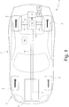
Figure 1 is a schematic view of a road vehicle with hybrid propulsion; -
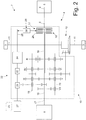
Figure 2 is a schematic view of a transmission of the road vehicle ofFigure 1 provided with a hydraulic system; -
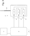
Figure 3 is a schematic view of an auxiliary electric motor of the hydraulic system ofFigure 2 , which auxiliary electric motor is controlled according to the control method of the present invention; -
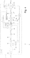
Figure 4 is a block diagram which illustrates a control logic used for controlling the auxiliary electric motor ofFigure 3 ; -
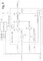
Figure 5 is a block diagram illustrating the method for determining an offset parameter of the equivalent impedance of the auxiliary electric motor ofFigure 3 ; and -
Figure 6 is a graph illustrating the torque-rotation speed characteristic of the auxiliary electric motor ofFigure 3 . - In
Figure 1 ,number 1 denoted as a whole a road vehicle with hybrid propulsion having twofront wheels 2 and tworear drive wheels 3, which receive the drive torque from a 4 hybrid powertrain system. - The
hybrid powertrain system 4 comprises an internalcombustion heat engine 5, which is arranged in a front position and is provided with adrive shaft 6, atransmission 7, which transmits the drive torque generated by theheat engine 5 to therear drive wheels 3, and a reversible electric machine 8 (that is, which can function both as an electric motor by absorbing electric energy and generating a mechanical drive torque, and as electric generator by absorbing mechanical energy and generating electric energy) which is mechanically connected to thetransmission 7. - The
transmission 7 comprises atransmission shaft 9 which on one side is angularly integral withdrive shaft 6 and the other side is mechanically connected with adual clutch gearbox 10, which is arranged in the rear position and transmits the motion to therear drive wheels 3 by means of twoaxle shafts 11 that receive the motion from adifferential 12. The reversibleelectric machine 8 is mechanically connected to thedual clutch gearbox 10 as will be described later and is controlled by anelectronic power converter 13 connected to anaccumulation system 14 which is designed to store electric energy and is provided with chemical and/or super-capacitor batteries. - As illustrated in
Figure 2 , thedual clutch gearbox 10 comprises twoprimary shafts clutches primary shaft drive shaft 6 of the internal combustion heat engine 5). Moreover, thedual clutch gearbox 10 comprises twosecondary shafts 19 and 20, both of which are angularly integral with the entrance of thedifferential 11 which transmits the motion to therear drive wheels 3. Theelectric machine 8 has ashaft 21, which is permanently connected to theprimary shaft 15 so as to always rotate integrally with theprimary shaft 15 itself. - The
transmission 7 comprises a hydraulic system 22 (only partly and schematically illustrated inFigure 2 ), which has the function to circulate a lubricant oil needed for the lubrication of all the components and an actuation oil necessary for the operation of the hydraulic actuators (used for the engagement of the gears in thegearbox 10 and for the control of theclutches 17 and 18) through thetransmission 7 itself (that is, through thegearbox 10 and theclutches 17 and 18). Thehydraulic system 22 of thetransmission 7 comprises acirculation pump 23, which has the function to circulate the lubricant oil through the gearing of thegearbox 10 and the discs of theclutches hydraulic system 22 of thetransmission 7 comprises anactuation pump 24 providing the hydraulic pressure needed to operate the hydraulic actuators for engaging the gears (that is, the actuators of the synchronizers of the gearbox 10) and the actuators for controlling theclutches - The two
pumps gearbox 10 are operated by a through auxiliary carrier shaft 25 (that is, which passes through eachpump 23 and 24) which on one side is caused to rotate by afront drum 26 of theclutches carrier shaft 25 and the drive shaft 6 (namely between thecarrier shaft 25 and thefront drum 26 of theclutches 17 and 18) a freewheel 28 (or idle wheel 28) is interposed, which transmits or does not transmit the motion (that is, engages or does not engage) depending on the direction of the speed difference. Similarly, also between thecarrier shaft 25 and the auxiliary electric motor 27 a freewheel 29 (or idle wheel 29) is interposed, which transmits or does not transmit (namely engages or does not engage) depending on the direction of the speed difference. - When the
heat engine 5 is turned on (namely when thedrive shaft 6 of theheat engine 5 is rotating), the auxiliaryelectric motor 27 is kept turned off: the rotation speed imparted to thecarrier shaft 25 by thedrive shaft 6 of theheat engine 5 exceeds the rotation speed imparted to thecarrier shaft 25 by the auxiliary electric motor 27 (which is stopped), and then thefreewheel 28 is engaged and transmits the motion towards thepumps freewheel 29 is not engaged and "separates" the auxiliaryelectric motor 27 from thecarrier shaft 25; in other words, thecarrier shaft 25 is rotated by thedrive shaft 6 of theheat engine 5 while thecarrier shaft 25 is isolated from the auxiliaryelectric motor 27. - When the
heat engine 5 is turned off (namely when thedrive shaft 6 of theheat engine 5 is stopped), the auxiliaryelectric motor 27 is activated: the rotation speed imparted to thecarrier shaft 25 by thedrive shaft 6 of the heat engine 5 (which is stopped) is lower than the rotation speed imparted to thecarrier shaft 25 by the auxiliaryelectric motor 27 and then thefreewheel 29 is engaged, and therefore transmits the motion to thepumps freewheel 28 is not engaged and separates thedrive shaft 6 of theheat engine 5 from thecarrier shaft 25; in other words; thecarrier shaft 25 is rotated by the auxiliaryelectric motor 27 while thecarrier shaft 25 is insulated from thedrive shaft 6 of theheat engine 5. - As illustrated in
Figure 3 , the auxiliaryelectric motor 27 is a three-phase alternating current electric motor havingpower supply terminals 30 through which the electric energy is transmitted. In the schematic representation ofFigure 3 , inside of the auxiliaryelectric motor 27 threeequivalent impedances 31 connected together in a triangle (but could also be connected in a star shape) are illustrated; of course in reality the internal electric circuit of the auxiliaryelectric motor 27 is much more complex and articulated than what schematically shown inFigure 3 . The auxiliaryelectric motor 27 is controlled by a powerelectronic converter 32 connected to thestorage system 14; the powerelectronic converter 32 converts the DC current supplied by thestorage system 14 into three-phase alternating current at variable frequency to control the auxiliaryelectric motor 27. - A
control unit 33 is provided, which supervises the operation of thehydraulic system 22, and then, among other things, controls the powerelectronic converter 32 to operate, when necessary, the auxiliary electric motor 27 (namely to turn on the auxiliaryelectric motor 27 in case of purely electric traction with theheat engine 5 turned off). - As illustrated in
Figure 4 , inside the control unit 33 acontrol module 34 is provided, which supervises the operation of the auxiliaryelectric motor 27 by directly controlling the powerelectronic converter 32. Thecontrol module 34 receives as input the requested torque Req_Torque that must be applied by the auxiliaryelectric motor 27 to the carrier shaft 25 (being determined mainly based on the requested pressure of the oil used for the hydraulic actuation, namely the oil pumped by the actuation pump 24) and the requested rotation speed Req_Speed that the auxiliaryelectric motor 27 must impart to the carrier shaft 25 (being determined mainly based on the requested flow rate of the oil used for lubrication, namely the oil pumped by the circulation pump 23). In asubtractor block 35 the actual rotation speed Act_Speed (estimated by anestimator block 36 based on the voltage phase Floating_Phs_Voltage of the electric motor 27) is subtracted from the requested rotation speed Req_Speed to calculate a speed error which is provided to aPID control block 37 which determines the sustenance torque CL_Torque needed to obtain the requested rotation speed Req_Speed. Anestimator block 38 determines by means of a map (being experimentally determined and stored in a non-volatile memory of the control unit 33) a friction torque Friction_Torque which is equal to the mechanical friction inside the auxiliaryelectric motor 27; the map provides the friction torque Friction_Torque based on the actual rotation speed Act_Speed and on the internal temperature Motor_Temp of the auxiliary electric motor 27 (measured by a temperature sensor or estimated in the absence of the temperature sensor). Two addingblocks 39 add, one to the other, the requested torque Req_Torque, the sustenance torque CL_Torque, and the friction torque Friction_Torque to determine the target torque Tgt_Torque. The target torque Tgt_Torque is filtered through alimiting block 40 which limits the maximum value of the target torque Tgt_Torque (so as not to exceed the mechanical limits of the auxiliary electric motor 27), and then is supplied to acalculation block 41, which calculates the target current Tgt_Current by dividing the target torque Tgt_Torque by the torque constant KT (which is a fixed parameter that never changes, is determined experimentally and is stored in a non-volatile memory of the control unit 33). - The target current Tgt_Current is filtered through a
limiting block 42 which limits the maximum value of the target current Tgt_Current (so as not to exceed the limits of the auxiliary electric motor 27), and then is supplied to acalculation block 43 which calculates the voltage drop V_I inside the auxiliaryelectric motor 27 by multiplying the target current Tgt_Current by the equivalent impedance RLS of the auxiliaryelectric motor 27; the equivalent impedance RLS of the auxiliaryelectric motor 27 is provided by a map M (being experimentally determined and stored in a non-volatile memory of the control unit 33) based on the internal temperature of the auxiliaryelectric motor 27 and on the actual rotation speed Act_Speed. A compensator block 44 (described in detail hereinafter) is provided, which provides an offset parameter RLS_offset (consisting of a single numeric value) that is added to the equivalent impedance RLS of the auxiliaryelectric motor 27 supplied by the map M and serves to compensate for the effect of the constructive dispersion (namely the construction tolerance) of the different components; the offset parameter RLS_offset is algebraically added to the equivalent impedance RLS of the auxiliaryelectric motor 27 provided by the map M, namely the offset parameter RLS_offset can be negative or positive and therefore can decrease or increase the value of the equivalent impedance RLS. - A
calculation block 45 determines the counter-electromotive force EMF of the auxiliaryelectric motor 27 by multiplying the actual rotation speed Act_Speed by the speed constant KV (which is a fixed parameter that never changes, is determined experimentally and is stored in a non-volatile memory of the control unit 33). An addingblock 46 determines the voltage control V_Control to be applied to thepower supply terminals 30 of theelectric motor 27 by adding the voltage drop V_I inside the auxiliaryelectric motor 27 to the counter-electromotive force EMF of the auxiliaryelectric motor 27. Downstream of the adding block 46 a limitingblock 47 is arranged, which limits the maximum value of the voltage control V_Control (so as not to exceed the limits of the auxiliary electric motor 27). The voltage control V_Control is supplied to acalculation block 48 which determines in a known manner the target duty-cycle Duty_Tgt, which is used to control the powerelectronic converter 32 based on the battery voltage V_Batt (namely thecalculation block 48 determines when to partialise in time the battery voltage V_Batt to obtain, on average, the application of the voltage control V_Control). - As illustrated in
Figure 5 , thecompensator block 44 determines the offset parameter RLS_offset based on the actual rotation speed Act_Speed (estimated by theestimator block 36 as described above), the inner temperature Motor_Temp of the auxiliaryelectric motor 27, the actual voltage Act_Voltage at thepower supply terminals 30 of theelectric motor 27, the battery voltage V_Batt, the requested rotation speed Req_Speed, and the DC current DC_Current which enters into thepower supply terminals 30 of theelectric motor 27. - A calculation block 49 (entirely similar to the calculation block 45) is provided, which determines the counter-electromotive force EMF of the auxiliary
electric motor 27 by multiplying the actual rotation speed Act_Speed by the speed constant KV. Asubtractor block 50 determines the voltage drop V_I inside the auxiliaryelectric motor 27 by subtracting the counter-electromotive force FCEM of the auxiliary electric motor 27 (calculated by the calculation block 49) from the actual voltage Act_Voltage at thepower supply terminals 30 of theelectric motor 27. - A
calculation block 51 determines the actual duty-cycle Act_Duty that is used for controlling the powerelectronic converter 32 based on the actual voltage Act_Voltage and on the battery voltage V_Batt; in other words, thecalculation block 51 performs the same type of calculation performed by thecalculation block 48 which determines the target duty-cycle Duty_Tgt based on the battery voltage V_Batt and on the voltage control V_Control). Adivider block 52 calculates the current phase Phs_Current of the auxiliaryelectric motor 27 by dividing the DC current DC_Current that enters into thepower supply terminals 30 of theelectric motor 27 by the actual duty-cycle Act_Duty that is used to control the powerelectronic converter 32. Adivider block 53 calculates the estimated equivalent impedance RLS_Calc of the auxiliaryelectric motor 27 by dividing the voltage drop V_I inside the 27 auxiliary electric motor by the current phase Phs_Current of the auxiliaryelectric motor 27. - A calculation block 54 (totally similar to the calculation block 43) estimates the map equivalent impedance RLS_MAP of the auxiliary
electric motor 27 by means of the map M and based on the inner temperature of the auxiliaryelectric motor 27 and on the actual rotation speed Act_Speed. Asubtracter block 55 determines the offset parameter RLS_offset by subtracting the map equivalent impedance RLS_MAP of the auxiliaryelectric motor 27 from the estimated equivalent impedance RLS_Calc of the auxiliaryelectric motor 27. In other words, the offset parameter RLS_offset is determined based on the difference between the map equivalent impedance RLS_MAP of the auxiliaryelectric motor 27 being determined based on the map M and the estimated equivalent impedance RLS_Calc of the auxiliaryelectric motor 27 being determined based on voltage and current estimates. - The
calculation block 44 is associated to anactivator block 56 which activates the calculation of the offset parameter RLS_offset only in certain conditions, namely only when the auxiliaryelectric motor 27 has recovered its thermal condition (namely when the inner temperature Motor_Temp of the auxiliaryelectric motor 27 is operational, that is, it is above a predetermined threshold) and in the neighbourhood of a predetermined operating point P (established based on the actual rotation speed Act_Speed and on the requested rotation speed Req_Speed that indicates whether the actual rotation speed Act_Speed is stable or is likely to change significantly); in other words, theactivator block 56 determines the offset parameter RLS_offset only when the inner temperature Motor_Temp of the auxiliaryelectric motor 27 exceeds a predetermined threshold and only when the actual rotation speed Act_Speed of theelectric motor 27 is stable and is in the neighbourhood of a predetermined value. In this way, the offset parameter RLS_offset is determined so as to have the maximum precision possible (and thus the maximum possible efficacy) in the operating point P of the auxiliaryelectric motor 27 where it is most needed (namely in the operating point P of the auxiliaryelectric motor 27 where the negative effects of constructive dispersion of the components produce the greatest problems). - As illustrated in
Figure 6 , the BLDC type auxiliaryelectric motor 27 has a torque curve (namely the characteristic that correlates the torque T to the rotation speed ω) having an initial section wherein the torque T is constant as the rotation speed increases ω and an end section wherein the torque T decreases as the rotation speed increases ω (inFigure 6 a linear decrease of the torque T with the increasing rotation speed ω is illustrated, but could also be a parabolic decrease of the torque T as the rotation speed increases ω); the two sections of the torque curve of the auxiliaryelectric motor 27 are connected to each other in an elbow where a noticeable change of slope is performed. - The operating point P wherein the offset parameter RLS_offset is determined, is arranged at the elbow of the characteristic torque-rotation speed of the auxiliary
electric motor 27. In fact, as illustrated inFigure 6 , the characteristic torque-rotation speed of the auxiliaryelectric motor 27 has a pronounced elbow which connects two differently sloped substantially linear sections with different slope: the initial section where the torque T is substantially constant with as the rotation speed increases ω and an end section where the torque T decreases to zero as the rotation speed increases ω. By choosing the operating point P wherein the offset parameter RLS_offset is determined at the elbow of the characteristic torque-rotation speed of the auxiliaryelectric motor 27 the effectiveness of the offset parameter RLS_offset can be maximized. In fact, at the elbow of the characteristic torque-rotation speed the auxiliaryelectric motor 27 is more difficult to control because of the local non-linearity, and therefore it is precisely in this area that it is necessary to provide, as accurately as possible, the voltage drop V_I inside of the auxiliaryelectric motor 27. Furthermore, in the moments of maximum effort (that is, of maximum load), therefore in the most critical moments, the auxiliaryelectric motor 27 is operated at the elbow of the characteristic torque-rotation speed because in this area the auxiliaryelectric motor 27 generates the maximum torque T (which allows to obtain the maximum hydraulic pressure) at a high rotation speed ω (which allows to obtain a high hydraulic flow rate); it is therefore important that in moments of maximum effort (that is, of maximum load) the auxiliaryelectric motor 27 is controlled in the best possible way. - Preferably, the
calculation block 44 cyclically performs the calculation of the offset parameter RLS_offset both to apply statistical calculations that allow to reduce the incidence of accidental errors, and to constantly update the estimate so as to pursue any drift over time of the components. - In the embodiment described above, the offset parameter RLS_offset consists of a single numerical value; alternatively, the offset parameter RLS_offset may vary based on the actual rotation speed Act_Speed and/or of the inner temperature Motor_Temp of the electric motor (27).
- It is important to note that based on an alternative and completely equivalent embodiment, at least one of the maps mentioned above can be replaced by a corresponding mathematical model that has the same input/output coordinates of the maps; as the map, also the corresponding mathematical model is normally experimentally built by using a plurality of measurements performed by means of laboratory instruments.
- The control method described above has numerous advantages.
- First, the above described control method allows to effectively compensate for the negative effect of the constructive dispersion; in fact, by correcting the equivalent impedance RLS of the auxiliary
electric motor 27 by way of using the offset parameter RLS_offset the negative effect of the constructive dispersion can be significantly limited. In particular, an underestimation of the equivalent impedance RLS of the auxiliaryelectric motor 27 leads to apply a current higher than necessary thus risking to send in protection the power electronics for the excessive electric current consequently determining the shutdown of the electric motor 27 (therefore preventing the continuation of electric traction); instead, an overestimation of the equivalent impedance RLS of the auxiliaryelectric motor 27 leads to apply a current lower than necessary thus significantly reducing the performance of the electric motor 27 (namely hindering theelectric motor 27 from reaching the rated performance). - To summarize, the control method described above allows to obtain a high strength to the constructive dispersion (namely to the construction tolerance) even without a rotation speed sensor and without a current phase sensor (sensors that would considerably increase the overall cost of the electric motor 27).
- Furthermore, the control method described above is simple and inexpensive to implement, since it does not require the addition of any physical component (namely the hardware system is not modified in any way), but it is completely achievable via software. It is important to note that the control method described above does not required neither a high calculation capacity, nor an extended amount of memory and therefore its actuation is possible in a known control unit without the need for updates or upgrades.
Claims (14)
- A method to control an electric motor (27); the control method comprises the steps of:determining a target torque (Tgt_Torque);calculating a target current (Tgt_Current) by dividing the target torque (Tgt_Torque) by a torque constant (KT);determining an equivalent impedance (RLS) by means of a predetermined map (M);calculating the voltage drop (V_I) by multiplying the target current (Tgt_Current) by the equivalent impedance (RLS);calculating a counter-electromotive force (FCEM) by multiplying an actual rotation speed (Act_Speed) by a speed constant (KV); anddetermining a control voltage (V_Control) to be applied to the power supply terminals (30) of the electric motor (27) by adding the voltage drop (V_I) to the counter-electromotive force (FCEM);wherein the auxiliary electric motor (27) is of BLDC type and has a torque curve, namely the characteristic that correlates the torque (T) to the rotation speed (ω), having an initial section wherein the torque (T) is constant as the rotation speed increases (ω) and an end section wherein the torque (T) decreases as the rotation speed increases (ω); the two sections of the torque curve of the auxiliary electric motor (27) are connected to each other in an elbow where a change in slope is performed;the control method is characterized in that it comprises the further steps of:determining an offset parameter (RLS_offset) when the electric motor (27) is in the neighbourhood of a predetermined operating point (P); andcorrecting the equivalent impedance (RLS) provided by the predetermined map (M) by applying the offset parameter (RLS_offset);wherein the operating point (P) in which the offset parameter (RLS_offset) is determined is arranged at the elbow of the torque curve of the electric motor (27).
- The control method according to claim 1, wherein the offset parameter (RLS_offset) consists of a single numerical value, which can increase or decrease the equivalent impedance (RLS) provided by the predetermined map (M).
- The control method according to claim 1 or 2, wherein the offset parameter (RLS_offset) is added to or subtracted from the equivalent impedance (RLS) provided by the predetermined map (M).
- The control method according to claim 1, 2 or 3, wherein the offset parameter (RLS_offset) is determined when the inner temperature (Motor_Temp) of the electric motor (27) exceeds a predetermined threshold.
- The control method according any of the claims from 1 to 4, wherein the offset parameter (RLS_offset) is determined when the actual rotation speed (Act_Speed) of the electric motor (27) is in the neighborhood of a predetermined value.
- The control method according any of the claims from 1 to 5, wherein the step of determining the offset parameter (RLS_offset) comprises the further steps of:determining the map equivalent impedance (RLS_MAP) by means of the predetermined map (M);determining a voltage drop (V_I);determining a phase current (Phs_Current);calculating an estimated equivalent impedance (RLS_Calc) by dividing the voltage drop (V_I) by the phase current (Phs_Current); anddetermining the offset parameter (RLS_offset) by comparing the map equivalent impedance (RLS_MAP) with the estimated equivalent impedance (RLS_Calc).
- The control method according to claim 6 and comprising the further steps of:calculating the counter-electromotive force (FCEM) by multiplying the actual rotation speed (Act_Speed) by the speed constant (KV); andcalculating the voltage drop (V_I) by subtracting the counter-electromotive force (FCEM) from an actual voltage (Act_Voltage) at the ends of the power supply terminals (30) of the electric motor (27).
- The control method according to claim 6 or 7 and comprising the further steps of:determining an actual duty cycle (Act_Duty) which is used to control an electronic power converter (32) of the electric motor (27) based on the actual voltage (Act_Voltage) and on a battery voltage (V_Batt); andcalculating a phase current (Phs_Current) by multiplying a direct current (DC_Current) flowing into the power supply terminals (30) of the electric motor (27) by the actual duty cycle (Act_Duty).
- The control method according any of the claims from 1 to 8 and comprising the further steps of:calculating a speed error by subtracting the actual rotation speed (Act_Speed) from a requested rotation speed (Req_Speed);determining a sustenance torque (CL_Torque) based on the speed error by means of PID controller (37);determining a friction torque (Friction_Torque) based on the actual rotation speed (Act_Speed) and on an inner temperature (Motor_Temp) of the electric motor (27); andcalculating the target torque (Tgt_Torque) by adding the sustenance torque (CL_Torque), the friction torque (Friction_Torque) and a requested torque (Req_Torque) to be delivered by the electric motor (27).
- The control method according any of the claims from 1 to 9, wherein the torque constant (KT) is a constant number, which never changes.
- The control method according any of the claims from 1 to 10, wherein the speed constant (KV) is a constant number, which never changes.
- The control method according any of the claims from 1 to 11, wherein the electric motor (27) is part of a hydraulic system (22) of a transmission (7) of a vehicle (1) and causes the rotation of a carrier shaft (25) on which a circulation pump (23), which allows a lubricant oil to circulate, and/or an actuation pump (24), which provides the hydraulic pressure needed to operate the transmission (7) is fitted.
- The control method according to claim 12, wherein the electric motor (27) causes the rotation of the carrier shaft (25) through the interposition of a first freewheel (29).
- The control method according to claim 13, wherein the hydraulic system (22) comprises a second freewheel (28), which is designed to connect the carrier shaft (25) to a drive shaft (6) of an internal combustion heat engine (5).
Applications Claiming Priority (1)
| Application Number | Priority Date | Filing Date | Title |
|---|---|---|---|
| ITUB2015A003363A ITUB20153363A1 (en) | 2015-09-03 | 2015-09-03 | METHOD OF CONTROL OF AN ELECTRIC MOTOR WITH ADAPTATION OF THE VALUE OF EQUIVALENT IMPEDANCE |
Publications (2)
| Publication Number | Publication Date |
|---|---|
| EP3138724A1 true EP3138724A1 (en) | 2017-03-08 |
| EP3138724B1 EP3138724B1 (en) | 2021-02-24 |
Family
ID=54705746
Family Applications (1)
| Application Number | Title | Priority Date | Filing Date |
|---|---|---|---|
| EP16187080.3A Active EP3138724B1 (en) | 2015-09-03 | 2016-09-02 | Method to control an electric motor with adjustment of the value of the equivalent impedance |
Country Status (3)
| Country | Link |
|---|---|
| US (1) | US10011272B2 (en) |
| EP (1) | EP3138724B1 (en) |
| IT (1) | ITUB20153363A1 (en) |
Cited By (1)
| Publication number | Priority date | Publication date | Assignee | Title |
|---|---|---|---|---|
| CN111717029A (en) * | 2020-06-08 | 2020-09-29 | 北京汽车股份有限公司 | Limp-home mode low-voltage load power supply control method and system and hybrid electric vehicle |
Families Citing this family (2)
| Publication number | Priority date | Publication date | Assignee | Title |
|---|---|---|---|---|
| CN107634685A (en) * | 2017-11-04 | 2018-01-26 | 中山市普阳电子科技有限公司 | A kind of method for suppressing torque ripple based on adaptive noise cancel- ation |
| KR102496257B1 (en) * | 2017-12-19 | 2023-02-08 | 현대자동차주식회사 | Control method of electric oil pump |
Citations (3)
| Publication number | Priority date | Publication date | Assignee | Title |
|---|---|---|---|---|
| US6411052B1 (en) | 1999-09-17 | 2002-06-25 | Delphi Technologies, Inc. | Method and apparatus to compensate for resistance variations in electric motors |
| US20120080259A1 (en) | 2009-06-23 | 2012-04-05 | Jtekt Corporation | Motor control device and electric power steering apparatus |
| US20130035816A1 (en) * | 2010-09-28 | 2013-02-07 | Dynamic Controls | Method and control system for controlling mobility vehicles |
Family Cites Families (2)
| Publication number | Priority date | Publication date | Assignee | Title |
|---|---|---|---|---|
| JP3893972B2 (en) * | 1999-07-28 | 2007-03-14 | 株式会社日立製作所 | Motor-driven throttle valve control device, control method therefor, automobile, temperature measurement method for motor for driving throttle valve of automobile, method for measuring motor temperature |
| JP3998000B2 (en) * | 2004-03-24 | 2007-10-24 | 株式会社日立製作所 | Control device for hybrid four-wheel drive vehicle and hybrid four-wheel drive vehicle |
-
2015
- 2015-09-03 IT ITUB2015A003363A patent/ITUB20153363A1/en unknown
-
2016
- 2016-09-02 US US15/255,546 patent/US10011272B2/en active Active
- 2016-09-02 EP EP16187080.3A patent/EP3138724B1/en active Active
Patent Citations (3)
| Publication number | Priority date | Publication date | Assignee | Title |
|---|---|---|---|---|
| US6411052B1 (en) | 1999-09-17 | 2002-06-25 | Delphi Technologies, Inc. | Method and apparatus to compensate for resistance variations in electric motors |
| US20120080259A1 (en) | 2009-06-23 | 2012-04-05 | Jtekt Corporation | Motor control device and electric power steering apparatus |
| US20130035816A1 (en) * | 2010-09-28 | 2013-02-07 | Dynamic Controls | Method and control system for controlling mobility vehicles |
Non-Patent Citations (2)
| Title |
|---|
| AUSTIN HUGHES, ELECTRIC MOTORS AND DRIVES, 31 December 1990 (1990-12-31) |
| AUSTIN HUGHES: "ELECTRIC MOTORS AND DRIVES", 31 December 1990, pages: 1,80,89-93, XP002757329 * |
Cited By (1)
| Publication number | Priority date | Publication date | Assignee | Title |
|---|---|---|---|---|
| CN111717029A (en) * | 2020-06-08 | 2020-09-29 | 北京汽车股份有限公司 | Limp-home mode low-voltage load power supply control method and system and hybrid electric vehicle |
Also Published As
| Publication number | Publication date |
|---|---|
| ITUB20153363A1 (en) | 2017-03-03 |
| US10011272B2 (en) | 2018-07-03 |
| EP3138724B1 (en) | 2021-02-24 |
| US20170088126A1 (en) | 2017-03-30 |
Similar Documents
| Publication | Publication Date | Title |
|---|---|---|
| EP3139068B1 (en) | Method to control an electric motor of a hydraulic system of a transmission in a vehicle | |
| CN105799689B (en) | Hybrid vehicle and method of disengaging an overrunning clutch in a hybrid vehicle | |
| KR101241210B1 (en) | Oil pump controlling systen of hybrid vehicle and method thereof | |
| US8187146B2 (en) | Method to control a hybrid drive train | |
| JP5553175B2 (en) | Control device | |
| KR101076951B1 (en) | Control device for vehicle | |
| US8930051B2 (en) | Control device | |
| US10011272B2 (en) | Method to control an electric motor with adjustment of the value of the equivalent impedance | |
| JP5416062B2 (en) | Electric oil pump control device | |
| CN102939237A (en) | Method and device for automatically controlling the speed of an electric bicycle transmission | |
| JP2014196101A5 (en) | ||
| US20180208202A1 (en) | Control device | |
| US9022165B2 (en) | Vehicle lubrication flow control | |
| JP2013107543A (en) | Control device | |
| US8414270B2 (en) | Speed control of an electrically-actuated fluid pump | |
| JP2015016849A (en) | Oil pump system of hybrid vehicle and control method thereof | |
| JP2007320388A (en) | Controller for hybrid vehicle | |
| US20170305426A1 (en) | Dual motor drive unit and method of drivingly engaging a first motor of a dual motor drive unit with an output shaft | |
| KR20170000992A (en) | A driving force control method in case of clutch slipping of tmed hev engine | |
| KR20140048582A (en) | Method and apparatus for controlling oil pump of transminssion | |
| CN102791528B (en) | Controller for internal combustion engine | |
| CN104919224A (en) | Controller for continuously variable transmission | |
| JP6136140B2 (en) | Motor control device and electric pump unit | |
| WO2014054534A1 (en) | Hybrid vehicle control device | |
| JP2016060443A (en) | Vehicle control device, vehicle control method, and vehicle |
Legal Events
| Date | Code | Title | Description |
|---|---|---|---|
| PUAI | Public reference made under article 153(3) epc to a published international application that has entered the european phase |
Free format text: ORIGINAL CODE: 0009012 |
|
| STAA | Information on the status of an ep patent application or granted ep patent |
Free format text: STATUS: THE APPLICATION HAS BEEN PUBLISHED |
|
| AK | Designated contracting states |
Kind code of ref document: A1 Designated state(s): AL AT BE BG CH CY CZ DE DK EE ES FI FR GB GR HR HU IE IS IT LI LT LU LV MC MK MT NL NO PL PT RO RS SE SI SK SM TR |
|
| AX | Request for extension of the european patent |
Extension state: BA ME |
|
| STAA | Information on the status of an ep patent application or granted ep patent |
Free format text: STATUS: REQUEST FOR EXAMINATION WAS MADE |
|
| 17P | Request for examination filed |
Effective date: 20170330 |
|
| STAA | Information on the status of an ep patent application or granted ep patent |
Free format text: STATUS: EXAMINATION IS IN PROGRESS |
|
| 17Q | First examination report despatched |
Effective date: 20200602 |
|
| GRAP | Despatch of communication of intention to grant a patent |
Free format text: ORIGINAL CODE: EPIDOSNIGR1 |
|
| STAA | Information on the status of an ep patent application or granted ep patent |
Free format text: STATUS: GRANT OF PATENT IS INTENDED |
|
| INTG | Intention to grant announced |
Effective date: 20200917 |
|
| GRAS | Grant fee paid |
Free format text: ORIGINAL CODE: EPIDOSNIGR3 |
|
| GRAA | (expected) grant |
Free format text: ORIGINAL CODE: 0009210 |
|
| STAA | Information on the status of an ep patent application or granted ep patent |
Free format text: STATUS: THE PATENT HAS BEEN GRANTED |
|
| AK | Designated contracting states |
Kind code of ref document: B1 Designated state(s): AL AT BE BG CH CY CZ DE DK EE ES FI FR GB GR HR HU IE IS IT LI LT LU LV MC MK MT NL NO PL PT RO RS SE SI SK SM TR |
|
| REG | Reference to a national code |
Ref country code: CH Ref legal event code: EP |
|
| REG | Reference to a national code |
Ref country code: AT Ref legal event code: REF Ref document number: 1364011 Country of ref document: AT Kind code of ref document: T Effective date: 20210315 |
|
| REG | Reference to a national code |
Ref country code: IE Ref legal event code: FG4D |
|
| REG | Reference to a national code |
Ref country code: DE Ref legal event code: R096 Ref document number: 602016052999 Country of ref document: DE |
|
| REG | Reference to a national code |
Ref country code: LT Ref legal event code: MG9D |
|
| REG | Reference to a national code |
Ref country code: NL Ref legal event code: MP Effective date: 20210224 |
|
| PG25 | Lapsed in a contracting state [announced via postgrant information from national office to epo] |
Ref country code: PT Free format text: LAPSE BECAUSE OF FAILURE TO SUBMIT A TRANSLATION OF THE DESCRIPTION OR TO PAY THE FEE WITHIN THE PRESCRIBED TIME-LIMIT Effective date: 20210624 Ref country code: NO Free format text: LAPSE BECAUSE OF FAILURE TO SUBMIT A TRANSLATION OF THE DESCRIPTION OR TO PAY THE FEE WITHIN THE PRESCRIBED TIME-LIMIT Effective date: 20210524 Ref country code: FI Free format text: LAPSE BECAUSE OF FAILURE TO SUBMIT A TRANSLATION OF THE DESCRIPTION OR TO PAY THE FEE WITHIN THE PRESCRIBED TIME-LIMIT Effective date: 20210224 Ref country code: HR Free format text: LAPSE BECAUSE OF FAILURE TO SUBMIT A TRANSLATION OF THE DESCRIPTION OR TO PAY THE FEE WITHIN THE PRESCRIBED TIME-LIMIT Effective date: 20210224 Ref country code: GR Free format text: LAPSE BECAUSE OF FAILURE TO SUBMIT A TRANSLATION OF THE DESCRIPTION OR TO PAY THE FEE WITHIN THE PRESCRIBED TIME-LIMIT Effective date: 20210525 Ref country code: LT Free format text: LAPSE BECAUSE OF FAILURE TO SUBMIT A TRANSLATION OF THE DESCRIPTION OR TO PAY THE FEE WITHIN THE PRESCRIBED TIME-LIMIT Effective date: 20210224 Ref country code: BG Free format text: LAPSE BECAUSE OF FAILURE TO SUBMIT A TRANSLATION OF THE DESCRIPTION OR TO PAY THE FEE WITHIN THE PRESCRIBED TIME-LIMIT Effective date: 20210524 |
|
| REG | Reference to a national code |
Ref country code: AT Ref legal event code: MK05 Ref document number: 1364011 Country of ref document: AT Kind code of ref document: T Effective date: 20210224 |
|
| PG25 | Lapsed in a contracting state [announced via postgrant information from national office to epo] |
Ref country code: LV Free format text: LAPSE BECAUSE OF FAILURE TO SUBMIT A TRANSLATION OF THE DESCRIPTION OR TO PAY THE FEE WITHIN THE PRESCRIBED TIME-LIMIT Effective date: 20210224 Ref country code: PL Free format text: LAPSE BECAUSE OF FAILURE TO SUBMIT A TRANSLATION OF THE DESCRIPTION OR TO PAY THE FEE WITHIN THE PRESCRIBED TIME-LIMIT Effective date: 20210224 Ref country code: NL Free format text: LAPSE BECAUSE OF FAILURE TO SUBMIT A TRANSLATION OF THE DESCRIPTION OR TO PAY THE FEE WITHIN THE PRESCRIBED TIME-LIMIT Effective date: 20210224 Ref country code: RS Free format text: LAPSE BECAUSE OF FAILURE TO SUBMIT A TRANSLATION OF THE DESCRIPTION OR TO PAY THE FEE WITHIN THE PRESCRIBED TIME-LIMIT Effective date: 20210224 Ref country code: SE Free format text: LAPSE BECAUSE OF FAILURE TO SUBMIT A TRANSLATION OF THE DESCRIPTION OR TO PAY THE FEE WITHIN THE PRESCRIBED TIME-LIMIT Effective date: 20210224 |
|
| PG25 | Lapsed in a contracting state [announced via postgrant information from national office to epo] |
Ref country code: IS Free format text: LAPSE BECAUSE OF FAILURE TO SUBMIT A TRANSLATION OF THE DESCRIPTION OR TO PAY THE FEE WITHIN THE PRESCRIBED TIME-LIMIT Effective date: 20210624 |
|
| PG25 | Lapsed in a contracting state [announced via postgrant information from national office to epo] |
Ref country code: CZ Free format text: LAPSE BECAUSE OF FAILURE TO SUBMIT A TRANSLATION OF THE DESCRIPTION OR TO PAY THE FEE WITHIN THE PRESCRIBED TIME-LIMIT Effective date: 20210224 Ref country code: EE Free format text: LAPSE BECAUSE OF FAILURE TO SUBMIT A TRANSLATION OF THE DESCRIPTION OR TO PAY THE FEE WITHIN THE PRESCRIBED TIME-LIMIT Effective date: 20210224 Ref country code: AT Free format text: LAPSE BECAUSE OF FAILURE TO SUBMIT A TRANSLATION OF THE DESCRIPTION OR TO PAY THE FEE WITHIN THE PRESCRIBED TIME-LIMIT Effective date: 20210224 Ref country code: SM Free format text: LAPSE BECAUSE OF FAILURE TO SUBMIT A TRANSLATION OF THE DESCRIPTION OR TO PAY THE FEE WITHIN THE PRESCRIBED TIME-LIMIT Effective date: 20210224 |
|
| REG | Reference to a national code |
Ref country code: DE Ref legal event code: R097 Ref document number: 602016052999 Country of ref document: DE |
|
| PG25 | Lapsed in a contracting state [announced via postgrant information from national office to epo] |
Ref country code: ES Free format text: LAPSE BECAUSE OF FAILURE TO SUBMIT A TRANSLATION OF THE DESCRIPTION OR TO PAY THE FEE WITHIN THE PRESCRIBED TIME-LIMIT Effective date: 20210224 Ref country code: DK Free format text: LAPSE BECAUSE OF FAILURE TO SUBMIT A TRANSLATION OF THE DESCRIPTION OR TO PAY THE FEE WITHIN THE PRESCRIBED TIME-LIMIT Effective date: 20210224 Ref country code: SK Free format text: LAPSE BECAUSE OF FAILURE TO SUBMIT A TRANSLATION OF THE DESCRIPTION OR TO PAY THE FEE WITHIN THE PRESCRIBED TIME-LIMIT Effective date: 20210224 Ref country code: RO Free format text: LAPSE BECAUSE OF FAILURE TO SUBMIT A TRANSLATION OF THE DESCRIPTION OR TO PAY THE FEE WITHIN THE PRESCRIBED TIME-LIMIT Effective date: 20210224 |
|
| PLBE | No opposition filed within time limit |
Free format text: ORIGINAL CODE: 0009261 |
|
| STAA | Information on the status of an ep patent application or granted ep patent |
Free format text: STATUS: NO OPPOSITION FILED WITHIN TIME LIMIT |
|
| PG25 | Lapsed in a contracting state [announced via postgrant information from national office to epo] |
Ref country code: AL Free format text: LAPSE BECAUSE OF FAILURE TO SUBMIT A TRANSLATION OF THE DESCRIPTION OR TO PAY THE FEE WITHIN THE PRESCRIBED TIME-LIMIT Effective date: 20210224 |
|
| 26N | No opposition filed |
Effective date: 20211125 |
|
| PG25 | Lapsed in a contracting state [announced via postgrant information from national office to epo] |
Ref country code: SI Free format text: LAPSE BECAUSE OF FAILURE TO SUBMIT A TRANSLATION OF THE DESCRIPTION OR TO PAY THE FEE WITHIN THE PRESCRIBED TIME-LIMIT Effective date: 20210224 |
|
| REG | Reference to a national code |
Ref country code: CH Ref legal event code: PL |
|
| REG | Reference to a national code |
Ref country code: BE Ref legal event code: MM Effective date: 20210930 |
|
| PG25 | Lapsed in a contracting state [announced via postgrant information from national office to epo] |
Ref country code: IS Free format text: LAPSE BECAUSE OF FAILURE TO SUBMIT A TRANSLATION OF THE DESCRIPTION OR TO PAY THE FEE WITHIN THE PRESCRIBED TIME-LIMIT Effective date: 20210624 Ref country code: MC Free format text: LAPSE BECAUSE OF FAILURE TO SUBMIT A TRANSLATION OF THE DESCRIPTION OR TO PAY THE FEE WITHIN THE PRESCRIBED TIME-LIMIT Effective date: 20210224 |
|
| PG25 | Lapsed in a contracting state [announced via postgrant information from national office to epo] |
Ref country code: LU Free format text: LAPSE BECAUSE OF NON-PAYMENT OF DUE FEES Effective date: 20210902 Ref country code: IE Free format text: LAPSE BECAUSE OF NON-PAYMENT OF DUE FEES Effective date: 20210902 Ref country code: BE Free format text: LAPSE BECAUSE OF NON-PAYMENT OF DUE FEES Effective date: 20210930 |
|
| PG25 | Lapsed in a contracting state [announced via postgrant information from national office to epo] |
Ref country code: LI Free format text: LAPSE BECAUSE OF NON-PAYMENT OF DUE FEES Effective date: 20210930 Ref country code: CH Free format text: LAPSE BECAUSE OF NON-PAYMENT OF DUE FEES Effective date: 20210930 |
|
| PG25 | Lapsed in a contracting state [announced via postgrant information from national office to epo] |
Ref country code: HU Free format text: LAPSE BECAUSE OF FAILURE TO SUBMIT A TRANSLATION OF THE DESCRIPTION OR TO PAY THE FEE WITHIN THE PRESCRIBED TIME-LIMIT; INVALID AB INITIO Effective date: 20160902 |
|
| PG25 | Lapsed in a contracting state [announced via postgrant information from national office to epo] |
Ref country code: CY Free format text: LAPSE BECAUSE OF FAILURE TO SUBMIT A TRANSLATION OF THE DESCRIPTION OR TO PAY THE FEE WITHIN THE PRESCRIBED TIME-LIMIT Effective date: 20210224 |
|
| P01 | Opt-out of the competence of the unified patent court (upc) registered |
Effective date: 20230525 |
|
| PGFP | Annual fee paid to national office [announced via postgrant information from national office to epo] |
Ref country code: IT Payment date: 20230911 Year of fee payment: 8 Ref country code: GB Payment date: 20230926 Year of fee payment: 8 |
|
| PGFP | Annual fee paid to national office [announced via postgrant information from national office to epo] |
Ref country code: FR Payment date: 20230926 Year of fee payment: 8 Ref country code: DE Payment date: 20230928 Year of fee payment: 8 |