EP3138463A1 - Aid for mounting and demounting optical adaptor for endoscope - Google Patents
Aid for mounting and demounting optical adaptor for endoscope Download PDFInfo
- Publication number
- EP3138463A1 EP3138463A1 EP15786469.5A EP15786469A EP3138463A1 EP 3138463 A1 EP3138463 A1 EP 3138463A1 EP 15786469 A EP15786469 A EP 15786469A EP 3138463 A1 EP3138463 A1 EP 3138463A1
- Authority
- EP
- European Patent Office
- Prior art keywords
- optical adapter
- assisting tool
- endoscope
- distal end
- adapter
- Prior art date
- Legal status (The legal status is an assumption and is not a legal conclusion. Google has not performed a legal analysis and makes no representation as to the accuracy of the status listed.)
- Withdrawn
Links
- 230000003287 optical effect Effects 0.000 title claims abstract description 322
- 238000003780 insertion Methods 0.000 claims abstract description 50
- 230000037431 insertion Effects 0.000 claims abstract description 50
- 238000000034 method Methods 0.000 description 11
- 230000004048 modification Effects 0.000 description 8
- 238000012986 modification Methods 0.000 description 8
- 230000008859 change Effects 0.000 description 7
- 230000003247 decreasing effect Effects 0.000 description 7
- 230000000694 effects Effects 0.000 description 5
- 238000007689 inspection Methods 0.000 description 5
- 239000002184 metal Substances 0.000 description 5
- 239000011347 resin Substances 0.000 description 5
- 229920005989 resin Polymers 0.000 description 5
- 238000005452 bending Methods 0.000 description 4
- 239000000470 constituent Substances 0.000 description 4
- 230000009467 reduction Effects 0.000 description 4
- 230000008901 benefit Effects 0.000 description 3
- 230000007423 decrease Effects 0.000 description 3
- 230000006866 deterioration Effects 0.000 description 3
- 238000010586 diagram Methods 0.000 description 2
- 238000005286 illumination Methods 0.000 description 2
- 238000005299 abrasion Methods 0.000 description 1
- 238000004140 cleaning Methods 0.000 description 1
- 238000004891 communication Methods 0.000 description 1
- 238000005260 corrosion Methods 0.000 description 1
- 230000007797 corrosion Effects 0.000 description 1
- 230000008569 process Effects 0.000 description 1
- 238000012545 processing Methods 0.000 description 1
- 229910001220 stainless steel Inorganic materials 0.000 description 1
- 239000010935 stainless steel Substances 0.000 description 1
Images











Classifications
-
- G—PHYSICS
- G02—OPTICS
- G02B—OPTICAL ELEMENTS, SYSTEMS OR APPARATUS
- G02B23/00—Telescopes, e.g. binoculars; Periscopes; Instruments for viewing the inside of hollow bodies; Viewfinders; Optical aiming or sighting devices
- G02B23/24—Instruments or systems for viewing the inside of hollow bodies, e.g. fibrescopes
- G02B23/2407—Optical details
- G02B23/2423—Optical details of the distal end
-
- A—HUMAN NECESSITIES
- A61—MEDICAL OR VETERINARY SCIENCE; HYGIENE
- A61B—DIAGNOSIS; SURGERY; IDENTIFICATION
- A61B1/00—Instruments for performing medical examinations of the interior of cavities or tubes of the body by visual or photographical inspection, e.g. endoscopes; Illuminating arrangements therefor
- A61B1/00064—Constructional details of the endoscope body
- A61B1/00071—Insertion part of the endoscope body
- A61B1/0008—Insertion part of the endoscope body characterised by distal tip features
- A61B1/00096—Optical elements
-
- A—HUMAN NECESSITIES
- A61—MEDICAL OR VETERINARY SCIENCE; HYGIENE
- A61B—DIAGNOSIS; SURGERY; IDENTIFICATION
- A61B1/00—Instruments for performing medical examinations of the interior of cavities or tubes of the body by visual or photographical inspection, e.g. endoscopes; Illuminating arrangements therefor
- A61B1/00064—Constructional details of the endoscope body
- A61B1/00071—Insertion part of the endoscope body
- A61B1/0008—Insertion part of the endoscope body characterised by distal tip features
- A61B1/00101—Insertion part of the endoscope body characterised by distal tip features the distal tip features being detachable
-
- A—HUMAN NECESSITIES
- A61—MEDICAL OR VETERINARY SCIENCE; HYGIENE
- A61B—DIAGNOSIS; SURGERY; IDENTIFICATION
- A61B1/00—Instruments for performing medical examinations of the interior of cavities or tubes of the body by visual or photographical inspection, e.g. endoscopes; Illuminating arrangements therefor
- A61B1/00064—Constructional details of the endoscope body
- A61B1/00105—Constructional details of the endoscope body characterised by modular construction
-
- A—HUMAN NECESSITIES
- A61—MEDICAL OR VETERINARY SCIENCE; HYGIENE
- A61B—DIAGNOSIS; SURGERY; IDENTIFICATION
- A61B1/00—Instruments for performing medical examinations of the interior of cavities or tubes of the body by visual or photographical inspection, e.g. endoscopes; Illuminating arrangements therefor
- A61B1/00064—Constructional details of the endoscope body
- A61B1/0011—Manufacturing of endoscope parts
-
- A—HUMAN NECESSITIES
- A61—MEDICAL OR VETERINARY SCIENCE; HYGIENE
- A61B—DIAGNOSIS; SURGERY; IDENTIFICATION
- A61B1/00—Instruments for performing medical examinations of the interior of cavities or tubes of the body by visual or photographical inspection, e.g. endoscopes; Illuminating arrangements therefor
- A61B1/00112—Connection or coupling means
- A61B1/00121—Connectors, fasteners and adapters, e.g. on the endoscope handle
- A61B1/00126—Connectors, fasteners and adapters, e.g. on the endoscope handle optical, e.g. for light supply cables
-
- A—HUMAN NECESSITIES
- A61—MEDICAL OR VETERINARY SCIENCE; HYGIENE
- A61B—DIAGNOSIS; SURGERY; IDENTIFICATION
- A61B1/00—Instruments for performing medical examinations of the interior of cavities or tubes of the body by visual or photographical inspection, e.g. endoscopes; Illuminating arrangements therefor
- A61B1/00131—Accessories for endoscopes
- A61B1/0014—Fastening element for attaching accessories to the outside of an endoscope, e.g. clips, clamps or bands
-
- A—HUMAN NECESSITIES
- A61—MEDICAL OR VETERINARY SCIENCE; HYGIENE
- A61B—DIAGNOSIS; SURGERY; IDENTIFICATION
- A61B1/00—Instruments for performing medical examinations of the interior of cavities or tubes of the body by visual or photographical inspection, e.g. endoscopes; Illuminating arrangements therefor
- A61B1/00163—Optical arrangements
-
- G—PHYSICS
- G02—OPTICS
- G02B—OPTICAL ELEMENTS, SYSTEMS OR APPARATUS
- G02B23/00—Telescopes, e.g. binoculars; Periscopes; Instruments for viewing the inside of hollow bodies; Viewfinders; Optical aiming or sighting devices
- G02B23/24—Instruments or systems for viewing the inside of hollow bodies, e.g. fibrescopes
- G02B23/2476—Non-optical details, e.g. housings, mountings, supports
-
- H—ELECTRICITY
- H04—ELECTRIC COMMUNICATION TECHNIQUE
- H04N—PICTORIAL COMMUNICATION, e.g. TELEVISION
- H04N23/00—Cameras or camera modules comprising electronic image sensors; Control thereof
- H04N23/56—Cameras or camera modules comprising electronic image sensors; Control thereof provided with illuminating means
-
- H—ELECTRICITY
- H04—ELECTRIC COMMUNICATION TECHNIQUE
- H04N—PICTORIAL COMMUNICATION, e.g. TELEVISION
- H04N23/00—Cameras or camera modules comprising electronic image sensors; Control thereof
- H04N23/50—Constructional details
- H04N23/555—Constructional details for picking-up images in sites, inaccessible due to their dimensions or hazardous conditions, e.g. endoscopes or borescopes
Definitions
- the present invention relates to an endoscope optical adapter attachment/detachment assisting tool for attaching and detaching an optical adapter to and from a distal end portion of an insertion portion of an endoscope.
- insertion equipment to be inserted into a subject for example, an endoscope
- an endoscope used in the medical field, it is possible to, by inserting an elongated insertion portion into a body cavity of a subject, observe an inside of the body cavity and, if necessary, perform various kinds of treatment and the like using a treatment instrument inserted in a treatment instrument insertion channel provided in the endoscope.
- an endoscope used in the industrial field it is possible to, by inserting an elongated insertion portion of the endoscope into an object such as an inside of a jet engine and piping of a factory, perform observation, various kinds of treatment, inspection and the like for scratches, corrosion and the like of a region to be inspected in the object.
- an adapter-type endoscope provided with an optical adapter attachable to and detachable from a distal end portion of the insertion portion is known.
- optical adapters used for the adapter-type endoscope, and the optical adapters can change optical characteristics such as a view angle, an observation direction and the like by being attached to the distal end portion of the insertion portion of the endoscope.
- optical adapter is screwedly fixed to the distal end portion of the endoscope by a retaining ring, which is a ring-shaped member provided on the optical adapter, being held by a person's fingers.
- an optical adapter for performing observation in a lateral direction is in a situation that a finger touches a lens of an observation optical system and the like each time the retaining ring of the optical adapter is rotated, and cleaning work is required each time the optical adapter is attached.
- an amount of tightening force at the time of attaching the optical adapter to the distal end portion of the endoscope depends on frictional force between the O-shaped ring and the retaining ring. Therefore, in the conventional assisting tool, the amount of force of tightening the optical adapter to the distal end portion of the endoscope easily varies depending on a deterioration state of the O-shaped ring, and there is also a possibility that the retaining ring loosens during an inspection, and the optical adapter falls off from the distal end portion and drops into an object.
- the present invention has been made in view of the above situation, and an object is to propose an endoscope optical adapter attachment/detachment assisting tool capable of easily attaching an optical adapter to a distal end portion of an endoscope and capable of attaching the optical adapter to the distal end portion with a steady amount of force by preventing reduction in holding force internally holding the optical adapter even if attachment/detachment of the optical adapter is repeatedly performed.
- An endoscope optical adapter attachment/detachment assisting tool of an aspect of the present invention includes: a substantially cylindrical assisting tool body configured to contain and hold an optical adapter attachable to and detachable from a distal end portion of an insertion portion of an endoscope; an adapter seizing portion configured to come into contact with the optical adapter contained in the assisting tool body and press the optical adapter in a direction orthogonal to a direction of attaching and detaching the optical adapter to and from the distal end portion to seize the optical adapter; and an urging member configured to urge the adapter holding portion.
- an endoscope optical adapter attachment/detachment assisting tool capable of easily attaching an optical adapter to a distal end portion of an endoscope and capable of attaching the optical adapter to the distal end portion with a steady amount of force by preventing reduction in holding force internally holding the optical adapter even if attachment/detachment of the optical adapter is repeatedly performed.
- Fig. 1 is a diagram showing a configuration of an endoscope, an optical adapter and an endoscope optical adapter attachment/detachment assisting tool
- Fig. 2 is a perspective view showing a configuration of the optical adapter
- Fig. 3 is a cross-sectional view showing the configuration of the optical adapter
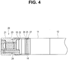
- Fig. 4 is a partial cross-sectional view showing a state that the optical adapter is attached to a distal end portion of the endoscope
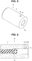
- Fig. 5 is a perspective view showing a configuration of the endoscope optical adapter attachment/detachment assisting tool
- Fig. 6 is a cross-sectional view showing the configuration of the endoscope optical adapter attachment/detachment assisting tool
- Fig. 1 is a diagram showing a configuration of an endoscope, an optical adapter and an endoscope optical adapter attachment/detachment assisting tool
- Fig. 2 is a perspective view showing a configuration of the optical adapter
- Fig. 3 is
- FIG. 7 is a cross-sectional view showing the configuration of the endoscope optical adapter attachment/detachment assisting tool in a state that the optical adapter is contained and held;
- Fig. 8 is an enlarged view of a circle VIII portion in Fig. 7 ;
- Fig. 9 is a partial cross-sectional view showing a state before the optical adapter is attached to the distal end portion of the insertion portion of the endoscope by the endoscope optical adapter attachment/detachment assisting tool;
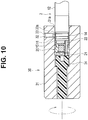
- Fig. 10 is a partial cross-sectional view showing a state that the optical adapter is attached to the distal end portion of the insertion portion of the endoscope by the endoscope optical adapter attachment/detachment assisting tool;
- Fig. 10 is a partial cross-sectional view showing a state that the optical adapter is attached to the distal end portion of the insertion portion of the endoscope by the endoscope optical adapter attachment/detachment assisting tool;
- FIG. 11 is a partial cross-sectional view showing a state that the endoscope optical adapter attachment/detachment assisting tool has been detached from the distal end portion of the insertion portion of the endoscope to which the optical adapter is attached;
- Fig. 12 shows a first modification, and is a plan view showing an example of a tapered face formed on a recess portion of a retaining ring of the optical adapter;
- Fig. 13 shows a second modification, and is a partial cross-sectional view showing a configuration in which a tapered face is formed on a lock pin of a plunger of the endoscope optical adapter attachment/detachment assisting tool.
- An endoscope system 1 of the present embodiment is configured having an endoscope 10, an optical adapter 20 and an endoscope optical adapter attachment/detachment assisting tool (hereinafter simply referred to as an assisting tool) 30 as shown in Fig. 1 .
- the endoscope 10 is configured being provided with mainly an insertion portion 2 configured to be inserted into a subject, an operation portion 3 provided on a proximal end side of the insertion portion 2, and a cable 4 for connecting the endoscope 10 to an external apparatus not shown which is provided with, for example, a display apparatus, the cable 4 extending from the operation portion 3.
- an industrial endoscope the insertion portion 2 of which is inserted into an object which is a structure such as a machine or a building
- components applicable to a medical endoscope for observing an inside of a living body such as a human body are included.
- the insertion portion 2 is configured with a distal end portion 11 arranged at a distal end, a bendable bending portion 12 arranged on a proximal end side of the distal end portion 11, and a deformable flexible tube portion 13 arranged on a proximal end side of the bending portion 12 and connected to a distal end side of the operation portion 3, which are connected to one another.
- the endoscope 10 may be in a form referred to as a so-called rigid endoscope which does not have the deformable flexible tube portion 13 on the insertion portion 2.
- the distal end portion 11 is provided with an image pickup portion and an illuminating light emitting portion not shown. Further, the operation portion 3 is provided with an angle operating lever 5 for operating bending of the bending portion 12.
- the cable 4 has a connector portion configured to be attachable to and detachable from the external apparatus though it is not shown.
- the external apparatus is provided with a power supplying portion configured to supply power to the endoscope 10, an image processing portion configured to process an image picked up by the image pickup portion of the endoscope 10 so that the image can be displayed on the display apparatus, and the like.
- the endoscope 10 is provided with a battery and has a configuration for wirelessly performing communication with the external apparatus, the cable 4 is unnecessary.
- the optical adapter 20 is configured having a substantially cylindrical lens holding frame 21 provided on a distal end side, and an annular retaining ring 22 which is rotatably fitted on a proximal end portion of the lens holding frame 21.
- an objective optical system 23 constituted by a plurality of objective lens groups, and an illumination optical system 24 including an illumination lens and a light guide configured to transmit illuminating light are included in the lens holding frame 21.
- a recess portion 25 having a circular section is formed on an outer circumferential portion of the retaining ring 22, and a tapered face 26 is formed on a wall portion forming the recess portion 25. Further, a female screw portion 27 is formed on an inner circumferential portion of the retaining ring 22.
- the optical adapter 20 is detachably attached by the retaining ring 22 being screwed to the distal end portion 11 of the insertion portion 2 of the endoscope 10 and can change optical characteristics of the endoscope 10.
- the optical adapter 20 is attached to the distal end portion 11 by the distal end portion 11 of the endoscope 10 being insertedly fitted from an opening of the retaining ring 22, and the female screw portion 27 of the retaining ring 22 being screwed to a male screw portion 14 formed on an outer circumferential portion of the distal end portion 11.
- an O-shaped ring 15 provided on the distal end portion 11 comes into close contact with a proximal end face of the lens holding frame 21 of the optical adapter 20, and the optical adapter 20 is attached to the distal end portion 11 in a state of being watertightly held.
- optical adapters 20 there are a plurality of kinds of optical adapters 20 exist, and it is possible to change various optical characteristics, such as a view angle, such as close-up photography, wide-angle and enlargement (view from a distance), and an observation direction, such as front view, lateral view and oblique view, according to the kind of the optical adapter 20 to be attached to the distal end portion 11 of the endoscope 10.
- a view angle such as close-up photography, wide-angle and enlargement (view from a distance)
- observation direction such as front view, lateral view and oblique view
- the assisting tool 30 is cast in metal such as stainless steel, rigid resin or the like and has a cylindrical assisting tool body 31 configured to contain and hold the optical adapter 20.
- a hole portion 32 is formed in an inner diameter center direction, and a plunger (spring plunger) 33 as an urging member is arranged in the hole portion 32.
- the plunger 33 is screwed in the hole portion 32 and is arranged so that, by an amount of screw into the hole portion 32 being adjusted, a lock pin 33a as an adapter seizing portion which is urged by an internal coil spring not shown and which can freely project and retreat, projects from an inner circumferential face of the assisting tool body 31 by a predetermined length.
- an axial direction position restricting member 34 for positioning the optical adapter 20 in an axial direction is screwed and provided inside the assisting tool body 31, whereby, a distal end of the assisting tool 30 is blocked and forms a cylindrical shape having a bottom and having, at a proximal end, an opening 31a where a tapered face is formed.
- the optical adapter 20 is inserted into the assisting tool 30 from the opening 31a side of the assisting tool body 31, and the assisting tool 30 contains and holds the optical adapter 20 in a state that the optical adapter 20 is inserted up to a position where a distal end face is in contact with a proximal end face of the axial direction position restricting member 34 as shown in Fig. 7 .
- a position of the optical adapter 20 contained in the assisting tool 30 around a longitudinal axis is adjusted so that the lock pin 33a of the plunger 33 is fitted in the recess portion 25 formed on the retaining ring 22 and seizes the retaining ring 22.
- the optical adapter 20 is held in the assisting tool body 31 of the assisting tool 30 in a state of being pressed in an inner diameter direction orthogonal to a longitudinal direction, by the lock pin 33a of the plunger 33 being fitted in the recess portion 25 of the retaining ring 22. Thereby, the optical adapter 20 is prevented from falling off from the assisting tool body 31 of the assisting tool 30.
- the assisting tool 30 is attached by a user so as to enclose the distal end portion 11 of the insertion portion 2 of the endoscope 10 from the opening 31a on the assisting tool body 31 side.
- the assisting tool 30 is rotated in a predetermined direction, and the optical adapter 20 is attached to the distal end portion 11 by the female screw portion 27 of the retaining ring 22 of the optical adapter 20 in the assisting tool body 31 and the male screw portion 14 of the distal end portion 11 being screwed to each other as shown in Fig. 10 .
- the lock pin 33a of the plunger 33 provided on the assisting tool body 31 of the assisting tool 30 is in a state of projecting in a direction orthogonal to a direction of attaching and detaching the optical adapter 20 to or from the distal end portion 11 and being fitted in the recess portion 25 of the retaining ring 22 and seizing the retaining ring 22.
- the lock pin 33a of the plunger 33 presses and seizes the retaining ring 22 in the direction orthogonal to the direction of attaching and detaching the optical adapter 20 to and from the distal end portion 11.
- the optical adapter 20 is contained in the assisting tool body 31 of the assisting tool 30 with sufficient holding force without running on idle, against rotation torque at the time of screwing the retaining ring 22 of the optical adapter 20 and the distal end portion 11 of the endoscope 10 to each other.
- the user can certainly fasten the retaining ring 22 of the optical adapter 20 to the distal end portion 11 by rotating the assisting tool 30 in the predetermined direction.
- the lock pin 33a of the plunger 33 retreats into the plunger 33 along a tapered face 26 formed on the recess portion 25 and comes off from the recess portion 25, and the optical adapter 20 enters an unseized state in the assisting tool body 31 of the assisting tool 30.
- the optical adapter 20 attached to the distal end portion 11 is caused to leave the assisting tool body 31 as shown in Fig. 11 .
- the optical adapter 20 can be easily attached to the distal end portion 11 of the endoscope 10.
- the optical adapter 20 being attached to the distal end portion 11 of the insertion portion 2, the optical characteristics of the endoscope 10, such as a view angle, such as close-up photography, wide-angle and enlargement (view from a distance), and an observation direction are changed according to the kind of the attached optical adapter 20.
- the optical adapter 20 attached to the distal end portion 11 is removed with use of the assisting tool 30 in a procedure opposite to the procedure at the time of attaching the optical adapter 20, and the optical adapter 20 is contained and held in the assisting tool body 31 of the assisting tool 30.
- the user encloses the optical adapter 20 attached to the distal end portion 11 of the insertion portion 2 of the endoscope 10 into the assisting tool body 31 from the opening 31a side of the assisting tool body 31 of the assisting tool 30.
- the assisting tool 30 encloses the optical adapter 20 up to a position where the distal end face of the optical adapter 20 comes into contact with the proximal end face of the axial direction position restricting member 34, and is rotation-adjusted to such a position that the lock pin 33a of the plunger 33 is fitted in the recess portion 25 of the retaining ring 22 and seizes the retaining ring 22.
- the assisting tool 30 enters a state that the lock pin 33a of the plunger 33 seizes the retaining ring 22 of the optical adapter 20 with holding force enough to prevent the optical adapter 20 from running on idle, against rotation torque required at time of loosening the screwed state between the retaining ring 22 of the optical adapter 20 and the distal end portion 11.
- the assisting tool 30 is rotated in a direction opposite to the predetermined direction at the time of attachment to the distal end portion 11 of the endoscope 10 described above, and the screwed state between the female screw portion 27 of the retaining ring 22 of the optical adapter 20 in the assisting tool body 31 and the male screw portion 14 of the distal end portion 11 is loosened, so that the screwed state between the retaining ring 22 and the distal end portion 11 is released.
- the optical adapter 20 is removed from the distal end portion 11, and the optical adapter 20 is contained and held in the assisting tool body 31 in the state that the lock pin 33a of the plunger 33 seizes the retaining ring 22.
- the assisting tool 30 is configured to contain and hold the optical adapter 20 in the assisting tool body 31 by inserting the optical adapter 20 up to the axial direction position restricting member 34 of the assisting tool body 31, and the lock pin 33a of the plunger 33 seizing the retaining ring 22, being fitted in the recess portion 25 of the retaining ring 22.
- the optical adapter 20 contained and held in the assisting tool body 31 is prevented from running on idle by being seized by the plunger 33 even if the rotation torque required at the time of screwingly attaching or detaching the retaining ring 22 to or from the distal end portion 11 is applied at the time of being attached to or detaching from the distal end portion 11 of the insertion portion 2 of the endoscope 10, and the optical adapter 20 can be easily attached to or detached from the distal end portion 11 with a predetermined amount of force.
- the assisting tool 30 has an advantage that it is possible to prevent loss of the optical adapter 20 because the assisting tool 30 contains and holds the optical adapter 20 when the optical adapter 20 is not used without being attached to the distal end portion 11 of the endoscope 10.
- the assisting tool 30 of the present embodiment is in a configuration that the optical adapter 20 inside the assisting tool 30 is seized by the plunger 33, abrasion, deterioration and the like of the plunger 33 do not easily occur even if the optical adapter 20 is repeatedly attached to and detached from the distal end portion 11 of the endoscope 10, and, therefore, the assisting tool 30 is in a configuration that the force of holding the optical adapter 20 is prevented from decreasing.
- the assisting tool 30 is in a configuration that the optical adapter 20 does not easily come off from the assisting tool body 31 because the lock pin 33a of the plunger 33 is fitted in the recess portion 25 of the retaining ring 22 to maintain a seized state, and the assisting tool 30 can prevent loss of the optical adapter 20.
- an amount of fastening or loosening force at the time of attaching or detaching the optical adapter 20 to or from the distal end portion 11 of the endoscope 10 becomes constant, and, therefore, the assisting tool 30 can stably attach or detach the optical adapter 20 to or from the distal end portion 11.
- the assisting tool 30 of the present embodiment is configured to be capable of easily attaching the optical adapter 20 to the distal end portion 11 of the insertion portion 2 of the endoscope 10, and capable of attaching the optical adapter 20 to the distal end portion 11 with a stable amount of force, preventing the force of internally holding the optical adapter 20 from decreasing even if attachment and detachment of the optical adapter 20 is repeatedly performed.
- the optical adapter 20 can appropriately adjust the holding force by the lock pin 33a of the plunger 33 of the assisting tool 30 by changing an angle, a direction and the like of the tapered face 26 provided around the recess portion 25 formed on the retaining ring 22, and can set the amount of holding force at the time of attaching and detaching the optical adapter 20 to and from the distal end portion 11 by the assisting tool 30 can be set.
- a configuration is also possible in which the tapered face 26 is provided only on a direction R side of the recess portion 25 where the retaining ring 22 is rotated at the time of attaching the optical adapter 20 to the distal end portion 11 of the insertion portion 2 of the endoscope 10, for example, as shown in Fig. 12 .
- the lock pin 33a of the plunger 33 of the assisting tool 30 comes into contact with a wall face of the recess portion 25 where the tapered face 26 is not provided, at the time of attaching the optical adapter 20 to the distal end portion 11, the holding force by the lock pin 33a can be increased. Therefore, it becomes difficult for the lock pin 33a to come off from the recess portion 25, and it is possible to increase the amount of the holding force at the time of attaching the optical adapter 20 to the distal end portion 11 by the assisting tool 30.
- a configuration is also possible in which the tapered face 26 is not provided on the recess portion 25, and a tapered face 33b is provided on the lock pin 33a side of the plunger 33 of the assisting tool 30.
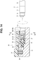
- Fig. 14 is a partial cross-sectional view showing a state before an optical adapter is attached to a distal end portion of an endoscope by an endoscope optical adapter attachment/detachment assisting tool
- Fig. 15 is a cross-sectional view along a XV-XV line in Fig. 14
- Fig. 16 is a partial cross-sectional view showing a state that the optical adapter is attached to the distal end portion of the insertion portion of the endoscope by the endoscope optical adapter attachment/detachment assisting tool
- Fig. 17 is a partial cross-sectional view showing a state that the endoscope optical adapter attachment/detachment assisting tool has been detached from the distal end portion of the insertion portion of the endoscope to which the optical adapter is attached.
- a structure for holding and fixing the optical adapter 20 in the assisting tool body 31 is in a lever-type configuration unlike the plunger 33 of the first embodiment.
- the assisting tool 30 is provided with a holding lever 35 as an adapter seizing member configured to hold the optical adapter 20 inside the assisting tool body 31 as shown in Figs. 14 and 15 .
- the holding lever 35 is formed with metal or rigid resin and provided in a groove portion 31b along a longitudinal direction which is formed on the assisting tool body 31 of the assisting tool 30.
- the holding lever 35 is rotatably held in the groove portion 31b by a pin member 38 and has an adapter seizing portion 36 configured to come into contact with the retaining ring 22 of the optical adapter 20, on a proximal end portion, and an operation projection portion 37 projecting so that the user can press it, on a distal end portion.
- the assisting tool body 31 is provided with a coil spring 39 as an urging member configured to urge the distal end portion of the holding lever 35 to be on the operation projection portion 37 side, in an outer diameter direction. Therefore, the holding lever 35 is caused to be in a state of projecting from the groove portion 31b of the assisting tool body 31 by urging force of the coil spring 39, and is caused to rotate around the pin member 38 by the operation projection portion 37 being pressed into the assisting tool body 31 by the user.
- a coil spring 39 as an urging member configured to urge the distal end portion of the holding lever 35 to be on the operation projection portion 37 side, in an outer diameter direction. Therefore, the holding lever 35 is caused to be in a state of projecting from the groove portion 31b of the assisting tool body 31 by urging force of the coil spring 39, and is caused to rotate around the pin member 38 by the operation projection portion 37 being pressed into the assisting tool body 31 by the user.
- the adapter seizing portion 36 has a holding face 36b with a recessedly curved section, on which recesses and projections to be engaged with a knurling 22a formed on an outer circumference of the retaining ring 22 of the optical adapter 20 are formed.
- the holding lever 35 holds the optical adapter 20 by the urging force of the coil spring 39, by the holding face 36b of the adapter seizing portion 36 being in contact with the retaining ring 22 of the optical adapter 20, pressing the retaining ring 22.
- the assisting tool 30 is configured to hold the optical adapter 20 in such a manner that the retaining ring 22 is prevented from running on idle against the rotation torque required at the time of screwing the retaining ring 22 of the optical adapter 20 to the distal end portion 11 of the endoscope 10, by the holding face 36b, on which the recesses and projections are formed, being engaged with the knurling 22a of the retaining ring 22 of the optical adapter 20.
- the optical adapter 20 here is in a configuration that the recess portion 25 is not formed on the retaining ring 22.
- the assisting tool 30 is attached by the user so as to enclose the distal end portion 11 of the insertion portion 2 of the endoscope 10 from the opening 31a on the assisting tool body 31 side.
- the assisting tool 30 is rotated in the predetermined direction, and the optical adapter 20 is attached to the distal end portion 11 by the female screw portion 27 of the retaining ring 22 of the optical adapter 20 in the assisting tool body 31 and the male screw portion 14 of the distal end portion 11 being screwed to each other as shown in Fig. 16 .
- the holding face 36b of the adapter seizing portion 36 provided on the holding lever 35 of the assisting tool 30 is in the state of being engaged with the knurling 22a of the retaining ring 22.
- the adapter seizing portion 36 provided on the assisting tool body 31 of the assisting tool 30 is in a state of seizing the optical adapter 20, pressing the retaining ring 22 in the direction orthogonal to the direction of attaching and detaching the optical adapter 20 to and from the distal end portion 11. That is, the adapter seizing portion 36 presses and seizes the retaining ring 22 in the direction orthogonal to the direction of attaching and detaching the optical adapter 20 to and from the distal end portion 11.
- the optical adapter 20 is contained in the assisting tool body 31 of the assisting tool 30 with sufficient holding force without the retaining ring 22 engaged with the holding face 36b running on idle, against rotation torque at the time of screwing the retaining ring 22 of the optical adapter 20 and the distal end portion 11 of the endoscope 10 to each other.
- the user can certainly fasten the retaining ring 22 of the optical adapter 20 to the distal end portion 11 by rotating the assisting tool 30 in the predetermined direction.
- the optical adapter 20 attached to the distal end portion 11 is caused to leave the assisting tool body 31 as shown in Fig. 17 .
- the optical adapter 20 can be easily attached to the distal end portion 11 of the endoscope 10.
- the optical adapter 20 being attached to the distal end portion 11 of the insertion portion 2, the optical characteristics of the endoscope 10, such as a view angle, such as close-up photography, wide-angle and enlargement (view from a distance), and an observation direction are changed according to the kind of the attached optical adapter 20.
- the optical adapter 20 attached to the distal end portion 11 is removed with use of the assisting tool 30 in a procedure opposite to the procedure at the time of attaching the optical adapter 20, and the optical adapter 20 is contained and held in the assisting tool body 31 of the assisting tool 30.
- the assisting tool 30 of the present embodiment configured as described above has effects similar to those of the first embodiment and has an advantage that it is possible to prevent loss of the optical adapter 20 because the assisting tool 30 contains and holds the optical adapter 20 when the optical adapter 20 is not used without being attached to the distal end portion 11 of the endoscope 10.
- the assisting tool 30 is configured so that the adapter seizing portion 36 provided on the holding lever 35 receives the urging force of the coil spring 39 and holds the internal optical adapter 20, pressing the optical adapter 20, the coil spring 39 and the adapter seizing portion 36 provided on the holding lever 35 do not easily wear out, deteriorate or the like even if the optical adapter 20 is repeatedly attached to and detached from the distal end portion 11 of the endoscope 10. Therefore, the assisting tool 30 is configured so that decrease in the force of holding the optical adapter 20 is prevented.
- the assisting tool 30 is configured such that the optical adapter 20 does not easily fall off from the assisting tool body 31 because the state of the adapter seizing portion 36 provided on the holding lever 35 being engaged with the knurling 22a of the retaining ring 22, and pressing the knurling 22a is kept. Thereby, it is possible to prevent loss of the optical adapter 20.
- the assisting tool 30 can stably attach or detach the optical adapter 20 to or from the distal end portion 11. Thereby, it does not happen that the retaining ring 22 of the optical adapter 20 loosens during an inspection, and the optical adapter 20 is prevented from falling off from the distal end portion 11 and dropping into an object.
- the assisting tool 30 of the present embodiment is also configured to be capable of easily attaching the optical adapter 20 to the distal end portion 11 of the insertion portion 2 of the endoscope 10, and capable of attaching the optical adapter 20 to the distal end portion 11 with a stable amount of force, preventing the force of internally holding the optical adapter 20 from decreasing even if attachment and detachment of the optical adapter 20 is repeatedly performed.
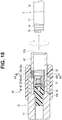
- Fig. 18 is a partial cross-sectional view showing a state before an optical adapter is attached to a distal end portion of an endoscope by an endoscope optical adapter attachment/detachment assisting tool
- Fig. 19 is a cross-sectional view along a XIX-XIX line in Fig. 18
- Fig. 20 is a partial cross-sectional view showing a state that the optical adapter is attached to the distal end portion of an insertion portion of the endoscope by the endoscope optical adapter attachment/detachment assisting tool
- Fig. 21 is a partial cross-sectional view showing a state that the endoscope optical adapter attachment/detachment assisting tool has been detached from the distal end portion of the insertion portion of the endoscope to which the optical adapter is attached.
- the structure for holding and fixing the optical adapter 20 in the assisting tool body 31 is different from the plunger 33 of the first embodiment and the holding lever 35 of the second embodiment.
- the assisting tool body 31 has a larger diameter portion 41 positioned on a distal end side and a small diameter portion 42 integrally formed with the larger diameter portion 41 and positioned on a proximal end side as shown in Fig. 18 .
- a notch portion 42a with a semicircular section is formed up to a middle position from an outer circumferential direction (see Fig. 19 ), and an adapter seizing portion 43 with a semicircular section and in a shape similar to the shape of the notch portion 42a is arranged.
- the adapter seizing portion 43 is formed with metal or rigid resin and has such a tapered face 43 a that a diameter of an outer circumferential face increases in a proximal end direction and a holding face 43b with a recessedly curved section, on which recesses and projections to be engaged with the knurling 22a formed on the outer circumference of the retaining ring 22 of the optical adapter 20 are formed, on an inner circumferential face (see Fig. 19 ).
- a cylindrical lock tube 45 formed with metal or rigid resin is arranged movably back and forth, enclosing the outer circumferential portion.
- the lock tube 45 is continuously urged in a proximal end direction by a coil spring 46 as an urging member enclosing the small diameter portion 42.
- the coil spring 46 continuously urges the lock tube 45 in the proximal end direction by an distal end being in contact with a contact face 41a to be a proximal end face of the larger diameter portion 41 of the assisting tool body 31 and a proximal end being in contact with a contact face 45b formed inside the lock tube 45.
- a tapered face 45a whose diameter increases in the proximal end direction is formed on a proximal end inner circumferential face of the lock tube 45.
- the tapered face 45a of the lock tube 45 is in surface-contact with the tapered face 43 a of the adapter seizing portion 43.
- the adapter seizing portion 43 is pressed by contact between the tapered face 43a formed on the outer circumferential face and the tapered face 45a of the lock tube 45 and elastically deforms in an inner diameter direction of the small diameter portion 42 of the assisting tool body 31.
- the force of being pressed by contact between the tapered face 43a formed on the outer circumferential face and the tapered face 45a of the lock tube 45 decreases, and the adapter seizing portion 43 is restored in an outer diameter direction of the small diameter portion 42 of the assisting tool body 31 from the state of being elastically deformed and pressed in the inner diameter direction by the lock tube 45.
- the assisting tool 30 configured in this way holds the optical adapter 20 by the holding face 43b of the adapter seizing portion 43 elastically deformed and pressed in the inner diameter direction of the small diameter portion 42 of the assisting tool body 31 by the lock tube 45 being in contact with the retaining ring 22 of the optical adapter 20, pressing the retaining ring 22.
- the assisting tool 30 is configured to hold the optical adapter 20 in such a manner that the retaining ring 22 is prevented from running on idle against the rotation torque required at the time of screwing the retaining ring 22 of the optical adapter 20 to the distal end portion 11 of the endoscope 10, by the holding face 43b of the adapter seizing portion 43, on which the recesses and projections are formed, being engaged with the knurling 22a of the retaining ring 22 of the optical adapter 20.
- the optical adapter 20 here also is in the configuration that recess portion 25 is not formed on the retaining ring 22.
- the assisting tool 30 is attached by the user so as to enclose the distal end portion 11 of the insertion portion 2 of the endoscope 10 from the opening 31a on the assisting tool body 31 side.
- the assisting tool 30 is rotated in the predetermined direction, and the optical adapter 20 is attached to the distal end portion 11 by the female screw portion 27 of the retaining ring 22 of the optical adapter 20 in the assisting tool body 31 and the male screw portion 14 of the distal end portion 11 being screwed to each other as shown in Fig. 20 .
- the holding face 43b of the adapter seizing portion 43 of the assisting tool 30 is in the state of being engaged with the knurling 22a of the retaining ring 22.
- the adapter seizing portion 43 provided on the assisting tool body 31 of the assisting tool 30 is in the state of seizing the optical adapter 20, pressing the retaining ring 22 in the direction orthogonal to the direction of attaching and detaching the optical adapter 20 to and from the distal end portion 11. That is, the adapter seizing portion 43 presses and seizes the retaining ring 22 in the direction orthogonal to the direction of attaching and detaching the optical adapter 20 to and from the distal end portion 11.
- the optical adapter 20 is contained in the assisting tool body 31 of the assisting tool 30 with sufficient holding force without the retaining ring 22 engaged with the holding face 43b running on idle, against rotation torque at the time of screwing the retaining ring 22 of the optical adapter 20 and the distal end portion 11 of the endoscope 10 to each other.
- the user can certainly fasten the retaining ring 22 of the optical adapter 20 to the distal end portion 11 by rotating the assisting tool 30 in the predetermined direction.
- the adapter seizing portion 43 is restored in the outer circumferential direction of the small diameter portion 42 of the assisting tool body 31 and leaves the retaining ring 22 of the optical adapter 20.
- the optical adapter 20 attached to the distal end portion 11 is caused to leave the assisting tool body 31 as shown in Fig. 21 .
- the optical adapter 20 can be easily attached to the distal end portion 11 of the endoscope 10.
- the optical adapter 20 being attached to the distal end portion 11 of the insertion portion 2, the optical characteristics of the endoscope 10, such as a view angle, such as close-up photography, wide-angle and enlargement (view from a distance), and an observation direction are changed according to the kind of the attached optical adapter 20.
- the optical adapter 20 attached to the distal end portion 11 is removed with use of the assisting tool 30 in a procedure opposite to the procedure at the time of attaching the optical adapter 20, and the optical adapter 20 is contained and held in the assisting tool body 31 of the assisting tool 30.
- the assisting tool 30 of the present embodiment configured as described above has effects similar to those of the first and second embodiments and has an advantage that it is possible to prevent loss of the optical adapter 20 because the assisting tool 30 contains and holds the optical adapter 20 when the optical adapter 20 is not used without being attached to the distal end portion 11 of the endoscope 10.
- the assisting tool 30 is configured so that the adapter seizing portion 43 holds the internal optical adapter 20, pressing the optical adapter 20, by the lock tube 45 receiving the urging force of the coil spring 46 and being urged in the proximal end direction, the coil spring 46, the lock tube 45 and the adapter seizing portion 43 do not easily wear out, deteriorate or the like even if the optical adapter 20 is repeatedly attached to and detached from the distal end portion 11 of the endoscope 10. Therefore, the assisting tool 30 is configured so that decrease in the force of holding the optical adapter 20 is prevented.
- the assisting tool 30 is configured such that the state of the adapter seizing portion 43 being engaged with the knurling 22a of the retaining ring 22, pressing the knurling 22a is kept, and the optical adapter 20 does not easily fall off from the assisting tool body 31. Thereby, it is possible to prevent loss of the optical adapter 20.
- the assisting tool 30 can stably attach or detach the optical adapter 20 to or from the distal end portion 11. Thereby, it does not happen that the retaining ring 22 of the optical adapter 20 loosens during an inspection, and the optical adapter 20 is prevented from falling off from the distal end portion 11 and dropping into an object.
- the assisting tool 30 of the present embodiment is also configured to be capable of easily attaching the optical adapter 20 to the distal end portion 11 of the insertion portion 2 of the endoscope 10, and capable of attaching the optical adapter 20 to the distal end portion 11 with a stable amount of force, preventing the force of internally holding the optical adapter 20 from decreasing even if attachment and detachment of the optical adapter 20 is repeatedly performed.
- the assisting tool 30 may have a structure in which the optical adapter 20 is held and fixed in the assisting tool body 31, as described in reference examples below.
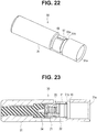
- Fig. 22 is a perspective view showing a configuration of an endoscope optical adapter attachment/detachment assisting tool of a first reference example
- Fig. 23 is a cross-sectional view showing the configuration of the endoscope optical adapter attachment/detachment assisting tool of the first reference example
- Fig. 24 is a perspective view showing a configuration of an endoscope optical adapter attachment/detachment assisting tool of a second reference example
- Fig. 23 is a cross-sectional view showing the configuration of the endoscope optical adapter attachment/detachment assisting tool of the second reference example.
- a notch portion 48 is formed on a midway portion of the assisting tool body 31, and an adapter seizing portion 51 in a form of a so-called C-shaped ring, which is a ring provided with a slit 51 a, is provided in the notch portion 48.
- the adapter seizing portion 51 is formed integrally with the assisting tool body 31 with metal or rigid resin. Further, a tapered face 51b is formed on a proximal end side of the adapter seizing portion 51 where the optical adapter 20 is inserted.
- the adapter seizing portion 51 seizes the retaining ring 22 of the optical adapter 20, pressing the retaining ring 22 in the inner diameter direction orthogonal to the longitudinal direction.
- the assisting tool 30 of the present modification is provided with a plurality of slits 55, four slits 55 here, which are parallel to the longitudinal direction and formed at almost equal intervals around a circumference, from the proximal end to a midway portion of the assisting tool body 31.
- an inward flange shaped retaining portion 56 for preventing the optical adapter 20 contained inside the assisting tool body 31 from falling off is projectingly formed in an inner diameter direction of a proximal end inner circumference portion of the assisting tool body 31.
- a projection portion 57 as an inward flange shaped adapter seizing portion configured to hold the retaining ring 22 of the optical adapter 20, being in contact with the retaining ring 22, when the optical adapter 20 is contained inside the assisting tool 30 is projectingly formed on a midway inner circumferential portion in the inner diameter direction.
- the assisting tool 30 configured as described above can cause the optical adapter 20 to be contained inside the assisting tool 30 or to leave from the inside by the diameter of the assisting tool body 31 being caused to increase by the four slits 55 of the assisting tool body 31.
- the assisting tool 30 seizes the optical adapter 20 in the assisting tool body 31.
- the assisting tool 30 described in the first to third embodiments described above may be in a configuration that the plurality of slits 55 parallel to the longitudinal direction are formed at almost equal intervals around the circumference of the assisting tool body 31 described in the present reference example, and the retaining portion 56 for preventing the optical adapter 20 contained inside the assisting tool body 31 from coming off is provided.
Landscapes
- Health & Medical Sciences (AREA)
- Life Sciences & Earth Sciences (AREA)
- Surgery (AREA)
- Physics & Mathematics (AREA)
- Optics & Photonics (AREA)
- Engineering & Computer Science (AREA)
- Biomedical Technology (AREA)
- Veterinary Medicine (AREA)
- Biophysics (AREA)
- Pathology (AREA)
- Radiology & Medical Imaging (AREA)
- Nuclear Medicine, Radiotherapy & Molecular Imaging (AREA)
- Public Health (AREA)
- Heart & Thoracic Surgery (AREA)
- Medical Informatics (AREA)
- Molecular Biology (AREA)
- Animal Behavior & Ethology (AREA)
- General Health & Medical Sciences (AREA)
- Astronomy & Astrophysics (AREA)
- General Physics & Mathematics (AREA)
- Manufacturing & Machinery (AREA)
- Multimedia (AREA)
- Signal Processing (AREA)
- Instruments For Viewing The Inside Of Hollow Bodies (AREA)
- Endoscopes (AREA)
Abstract
Description
- The present invention relates to an endoscope optical adapter attachment/detachment assisting tool for attaching and detaching an optical adapter to and from a distal end portion of an insertion portion of an endoscope.
- Recently, insertion equipment to be inserted into a subject, for example, an endoscope, is widely used in a medical field and an industrial field. In the case of an endoscope used in the medical field, it is possible to, by inserting an elongated insertion portion into a body cavity of a subject, observe an inside of the body cavity and, if necessary, perform various kinds of treatment and the like using a treatment instrument inserted in a treatment instrument insertion channel provided in the endoscope.
- Further, in the case of an endoscope used in the industrial field, it is possible to, by inserting an elongated insertion portion of the endoscope into an object such as an inside of a jet engine and piping of a factory, perform observation, various kinds of treatment, inspection and the like for scratches, corrosion and the like of a region to be inspected in the object.
- Especially, as the endoscope in the industrial field, an adapter-type endoscope provided with an optical adapter attachable to and detachable from a distal end portion of the insertion portion is known. There are a plurality of kinds of optical adapters used for the adapter-type endoscope, and the optical adapters can change optical characteristics such as a view angle, an observation direction and the like by being attached to the distal end portion of the insertion portion of the endoscope.
- A plurality of kinds of such optical adapters exist, and it becomes possible to change the view angle and the observation direction of the endoscope by attaching various kinds of optical adapters. Conventionally, at the time of attaching an optical adapter, the optical adapter is screwedly fixed to the distal end portion of the endoscope by a retaining ring, which is a ring-shaped member provided on the optical adapter, being held by a person's fingers.
- However, due to recent downsizing, diameter reduction and the like of optical adapters, it is difficult to perform work of attaching and detaching an optical adapter to and from the distal end portion of the endoscope. Especially, an optical adapter for performing observation in a lateral direction is in a situation that a finger touches a lens of an observation optical system and the like each time the retaining ring of the optical adapter is rotated, and cleaning work is required each time the optical adapter is attached.
- As a countermeasure for the situation, a technique for improving workability at the time of attachment by using an assisting tool which can grasp an outer circumference of an optical adapter is known as disclosed in U.S. Patent No.
US2005/0050707A1 . - However, the conventional assisting tool described in U.S. Patent No.
US2005/0050707A1 has a problem that, since an optical adapter is held by an internal O-shaped ring, the O-shaped ring is worn away, and holding force reduces when attachment and detachment of the optical adapter to/from a distal end portion of an endoscope is repeatedly performed. - Thus, in the case of the conventional assisting tool, there is also a possibility that, by reduction in holding force due to deterioration of the O-shaped ring, the optical adapter comes off from inside the assisting tool and is lost.
- By the way, in the conventional assisting tool, an amount of tightening force at the time of attaching the optical adapter to the distal end portion of the endoscope depends on frictional force between the O-shaped ring and the retaining ring. Therefore, in the conventional assisting tool, the amount of force of tightening the optical adapter to the distal end portion of the endoscope easily varies depending on a deterioration state of the O-shaped ring, and there is also a possibility that the retaining ring loosens during an inspection, and the optical adapter falls off from the distal end portion and drops into an object.
- Therefore, the present invention has been made in view of the above situation, and an object is to propose an endoscope optical adapter attachment/detachment assisting tool capable of easily attaching an optical adapter to a distal end portion of an endoscope and capable of attaching the optical adapter to the distal end portion with a steady amount of force by preventing reduction in holding force internally holding the optical adapter even if attachment/detachment of the optical adapter is repeatedly performed.
- An endoscope optical adapter attachment/detachment assisting tool of an aspect of the present invention includes: a substantially cylindrical assisting tool body configured to contain and hold an optical adapter attachable to and detachable from a distal end portion of an insertion portion of an endoscope; an adapter seizing portion configured to come into contact with the optical adapter contained in the assisting tool body and press the optical adapter in a direction orthogonal to a direction of attaching and detaching the optical adapter to and from the distal end portion to seize the optical adapter; and an urging member configured to urge the adapter holding portion.
- According to the present invention described above, it is possible to provide an endoscope optical adapter attachment/detachment assisting tool capable of easily attaching an optical adapter to a distal end portion of an endoscope and capable of attaching the optical adapter to the distal end portion with a steady amount of force by preventing reduction in holding force internally holding the optical adapter even if attachment/detachment of the optical adapter is repeatedly performed.
-
-
Fig. 1 relates to a first embodiment and is a diagram showing a configuration of an endoscope, an optical adapter and an endoscope optical adapter attachment/detachment assisting tool; -
Fig. 2 relates to the first embodiment and is a perspective view showing a configuration of the optical adapter; -
Fig. 3 relates to the first embodiment and is a cross-sectional view showing the configuration of the optical adapter; -
Fig. 4 relates to the first embodiment and is a partial cross-sectional view showing a state that the optical adapter is attached to a distal end portion of the endoscope; -
Fig. 5 relates to the first embodiment and is a perspective view showing a configuration of the endoscope optical adapter attachment/detachment assisting tool; -
Fig. 6 relates to the first embodiment and is a cross-sectional view showing the configuration of the endoscope optical adapter attachment/detachment assisting tool; -
Fig. 7 relates to the first embodiment and is a cross-sectional view showing the configuration of the endoscope optical adapter attachment/detachment assisting tool in a state that the optical adapter is contained and held; -
Fig. 8 relates to the first embodiment and is an enlarged view of a circle VIII portion inFig. 7 ; -
Fig. 9 relates to the first embodiment and is a partial cross-sectional view showing a state before the optical adapter is attached to the distal end portion of an insertion portion of the endoscope by the endoscope optical adapter attachment/detachment assisting tool; -
Fig. 10 relates to the first embodiment and is a partial cross-sectional view showing a state that the optical adapter is attached to the distal end portion of the insertion portion of the endoscope by the endoscope optical adapter attachment/detachment assisting tool; -
Fig. 11 relates to the first embodiment and is a partial cross-sectional view showing a state that the endoscope optical adapter attachment/detachment assisting tool has been detached from the distal end portion of the insertion portion of the endoscope to which the optical adapter is attached; -
Fig. 12 relates to the first embodiment, shows a first modification, and is a plan view showing an example of a tapered face formed on a recess portion of a retaining ring of the optical adapter; -
Fig. 13 relates to the first embodiment, shows a second modification, and is a partial cross-sectional view showing a configuration in which a tapered face is formed on a lock pin of a plunger of the endoscope optical adapter attachment/detachment assisting tool; -
Fig. 14 relates to a second embodiment and is a partial cross-sectional view showing a state before an optical adapter is attached to a distal end portion of an insertion portion of an endoscope by an endoscope optical adapter attachment/detachment assisting tool; -
Fig. 15 relates to the second embodiment and is a cross-sectional view along a XV-XV line inFig. 14 ; -
Fig. 16 relates to the second embodiments and is a partial cross-sectional view showing a state that the optical adapter is attached to the distal end portion of the insertion portion of the endoscope by the endoscope optical adapter attachment/detachment assisting tool; -
Fig. 17 relates to the second embodiments and is a partial cross-sectional view showing a state that the endoscope optical adapter attachment/detachment assisting tool has been detached from the distal end portion of the insertion portion of the endoscope to which the optical adapter is attached; -
Fig. 18 relates to a third embodiment and is a partial cross-sectional view showing a state before an optical adapter is attached to a distal end portion of an insertion portion of an endoscope by an endoscope optical adapter attachment/detachment assisting tool; -
Fig. 19 relates to the third embodiment and is a cross-sectional view along a XIX-XIX line inFig. 18 ; -
Fig. 20 relates to the third embodiment and is a partial cross-sectional view showing a state that the optical adapter is attached to the distal end portion of the insertion portion of the endoscope by the endoscope optical adapter attachment/detachment assisting tool; -
Fig. 21 relates to the third embodiment and is a partial cross-sectional view showing a state that the endoscope optical adapter attachment/detachment assisting tool has been detached from the distal end portion of the insertion portion of the endoscope to which the optical adapter is attached; -
Fig. 22 is a perspective view showing a configuration of an endoscope optical adapter attachment/detachment assisting tool of a first reference example; -
Fig. 23 is a cross-sectional view showing the configuration of the endoscope optical adapter attachment/detachment assisting tool of the first reference example; -
Fig. 24 is a perspective view showing a configuration of an endoscope optical adapter attachment/detachment assisting tool of a second reference example; and -
Fig. 25 is a cross-sectional view showing the configuration of the endoscope optical adapter attachment/detachment assisting tool of the second reference example. - Preferable embodiments of the present invention will be described below with reference to drawings. Note that, in each figure used in the description below, a different reduced scale is used for each component so that the component is shown in a size recognizable on a drawing, and the present invention is not limited only to the number of components, shapes of the components, a ratio of sizes of the components and relative positional relationships among the respective components shown in the figures. Further, in the description below, there may be a case where description is made on an assumption that upward and downward directions at time of facing a drawing correspond to upper and lower parts of a component, respectively.
- First, an optical unit and an endoscope of a first embodiment of the present invention will be described below based on drawings.
- Note that
Fig. 1 is a diagram showing a configuration of an endoscope, an optical adapter and an endoscope optical adapter attachment/detachment assisting tool;Fig. 2 is a perspective view showing a configuration of the optical adapter;Fig. 3 is a cross-sectional view showing the configuration of the optical adapter;Fig. 4 is a partial cross-sectional view showing a state that the optical adapter is attached to a distal end portion of the endoscope;Fig. 5 is a perspective view showing a configuration of the endoscope optical adapter attachment/detachment assisting tool;Fig. 6 is a cross-sectional view showing the configuration of the endoscope optical adapter attachment/detachment assisting tool;Fig. 7 is a cross-sectional view showing the configuration of the endoscope optical adapter attachment/detachment assisting tool in a state that the optical adapter is contained and held;Fig. 8 is an enlarged view of a circle VIII portion inFig. 7 ;Fig. 9 is a partial cross-sectional view showing a state before the optical adapter is attached to the distal end portion of the insertion portion of the endoscope by the endoscope optical adapter attachment/detachment assisting tool;Fig. 10 is a partial cross-sectional view showing a state that the optical adapter is attached to the distal end portion of the insertion portion of the endoscope by the endoscope optical adapter attachment/detachment assisting tool;Fig. 11 is a partial cross-sectional view showing a state that the endoscope optical adapter attachment/detachment assisting tool has been detached from the distal end portion of the insertion portion of the endoscope to which the optical adapter is attached;Fig. 12 shows a first modification, and is a plan view showing an example of a tapered face formed on a recess portion of a retaining ring of the optical adapter; andFig. 13 shows a second modification, and is a partial cross-sectional view showing a configuration in which a tapered face is formed on a lock pin of a plunger of the endoscope optical adapter attachment/detachment assisting tool. - First, a schematic configuration of the present embodiment will be described.
- An
endoscope system 1 of the present embodiment is configured having anendoscope 10, anoptical adapter 20 and an endoscope optical adapter attachment/detachment assisting tool (hereinafter simply referred to as an assisting tool) 30 as shown inFig. 1 . - First, a configuration of the
endoscope 10 of theendoscope system 1 will be described below. - The
endoscope 10 is configured being provided with mainly aninsertion portion 2 configured to be inserted into a subject, anoperation portion 3 provided on a proximal end side of theinsertion portion 2, and a cable 4 for connecting theendoscope 10 to an external apparatus not shown which is provided with, for example, a display apparatus, the cable 4 extending from theoperation portion 3. - Note that, as the
endoscope 10 here, an industrial endoscope, theinsertion portion 2 of which is inserted into an object which is a structure such as a machine or a building, is shown as an example, components applicable to a medical endoscope for observing an inside of a living body such as a human body are included. - The
insertion portion 2 is configured with adistal end portion 11 arranged at a distal end, abendable bending portion 12 arranged on a proximal end side of thedistal end portion 11, and a deformableflexible tube portion 13 arranged on a proximal end side of thebending portion 12 and connected to a distal end side of theoperation portion 3, which are connected to one another. Note that theendoscope 10 may be in a form referred to as a so-called rigid endoscope which does not have the deformableflexible tube portion 13 on theinsertion portion 2. - The
distal end portion 11 is provided with an image pickup portion and an illuminating light emitting portion not shown. Further, theoperation portion 3 is provided with anangle operating lever 5 for operating bending of thebending portion 12. - The cable 4 has a connector portion configured to be attachable to and detachable from the external apparatus though it is not shown. The external apparatus is provided with a power supplying portion configured to supply power to the
endoscope 10, an image processing portion configured to process an image picked up by the image pickup portion of theendoscope 10 so that the image can be displayed on the display apparatus, and the like. - Note that, if the
endoscope 10 is provided with a battery and has a configuration for wirelessly performing communication with the external apparatus, the cable 4 is unnecessary. - Next, a configuration of the
optical adapter 20 of theendoscope system 1 will be described below. - As shown in
Fig. 2 , theoptical adapter 20 is configured having a substantially cylindricallens holding frame 21 provided on a distal end side, and anannular retaining ring 22 which is rotatably fitted on a proximal end portion of thelens holding frame 21. - As shown in
Fig. 3 , an objectiveoptical system 23 constituted by a plurality of objective lens groups, and an illuminationoptical system 24 including an illumination lens and a light guide configured to transmit illuminating light are included in thelens holding frame 21. - Note that a
recess portion 25 having a circular section is formed on an outer circumferential portion of the retainingring 22, and atapered face 26 is formed on a wall portion forming therecess portion 25. Further, afemale screw portion 27 is formed on an inner circumferential portion of the retainingring 22. - As shown in
Fig. 4 , theoptical adapter 20 is detachably attached by the retainingring 22 being screwed to thedistal end portion 11 of theinsertion portion 2 of theendoscope 10 and can change optical characteristics of theendoscope 10. - More specifically, the
optical adapter 20 is attached to thedistal end portion 11 by thedistal end portion 11 of theendoscope 10 being insertedly fitted from an opening of the retainingring 22, and thefemale screw portion 27 of the retainingring 22 being screwed to amale screw portion 14 formed on an outer circumferential portion of thedistal end portion 11. - At this time, an O-shaped
ring 15 provided on thedistal end portion 11 comes into close contact with a proximal end face of thelens holding frame 21 of theoptical adapter 20, and theoptical adapter 20 is attached to thedistal end portion 11 in a state of being watertightly held. - Note that a plurality of kinds of
optical adapters 20 exist, and it is possible to change various optical characteristics, such as a view angle, such as close-up photography, wide-angle and enlargement (view from a distance), and an observation direction, such as front view, lateral view and oblique view, according to the kind of theoptical adapter 20 to be attached to thedistal end portion 11 of theendoscope 10. - Next, a configuration of the assisting
tool 30 of theendoscope system 1 will be described below. - As shown in
Figs. 5 and 6 , the assistingtool 30 is cast in metal such as stainless steel, rigid resin or the like and has a cylindrical assistingtool body 31 configured to contain and hold theoptical adapter 20. - On an outer circumferential portion of the assisting
tool body 31, ahole portion 32 is formed in an inner diameter center direction, and a plunger (spring plunger) 33 as an urging member is arranged in thehole portion 32. - The
plunger 33 is screwed in thehole portion 32 and is arranged so that, by an amount of screw into thehole portion 32 being adjusted, alock pin 33a as an adapter seizing portion which is urged by an internal coil spring not shown and which can freely project and retreat, projects from an inner circumferential face of the assistingtool body 31 by a predetermined length. - Inside the assisting
tool body 31, an axial directionposition restricting member 34 for positioning theoptical adapter 20 in an axial direction is screwed and provided. Thereby, a distal end of the assistingtool 30 is blocked and forms a cylindrical shape having a bottom and having, at a proximal end, anopening 31a where a tapered face is formed. - The
optical adapter 20 is inserted into the assistingtool 30 from theopening 31a side of the assistingtool body 31, and the assistingtool 30 contains and holds theoptical adapter 20 in a state that theoptical adapter 20 is inserted up to a position where a distal end face is in contact with a proximal end face of the axial directionposition restricting member 34 as shown inFig. 7 . - Note that, as shown in
Fig. 8 , a position of theoptical adapter 20 contained in the assistingtool 30 around a longitudinal axis is adjusted so that thelock pin 33a of theplunger 33 is fitted in therecess portion 25 formed on the retainingring 22 and seizes the retainingring 22. - Thus, the
optical adapter 20 is held in the assistingtool body 31 of the assistingtool 30 in a state of being pressed in an inner diameter direction orthogonal to a longitudinal direction, by thelock pin 33a of theplunger 33 being fitted in therecess portion 25 of the retainingring 22. Thereby, theoptical adapter 20 is prevented from falling off from the assistingtool body 31 of the assistingtool 30. - Next, description will be made on a procedure for attaching and detaching the
optical adapter 20 contained and held in the assistingtool 30 to and from thedistal end portion 11 of theinsertion portion 2 to change the optical characteristics of theendoscope 10, such as a view angle, such as close-up photography, wide-angle and enlargement (view from a distance), an observation direction and the like by the assistingtool 30 of the present embodiment configured as described above at time of using theendoscope 10. - First, in a state that the
optical adapter 20 is contained and held in the assistingtool body 31 as shown inFig. 9 , the assistingtool 30 is attached by a user so as to enclose thedistal end portion 11 of theinsertion portion 2 of theendoscope 10 from theopening 31a on the assistingtool body 31 side. - Then, the assisting
tool 30 is rotated in a predetermined direction, and theoptical adapter 20 is attached to thedistal end portion 11 by thefemale screw portion 27 of the retainingring 22 of theoptical adapter 20 in the assistingtool body 31 and themale screw portion 14 of thedistal end portion 11 being screwed to each other as shown inFig. 10 . - At this time, the
lock pin 33a of theplunger 33 provided on the assistingtool body 31 of the assistingtool 30 is in a state of projecting in a direction orthogonal to a direction of attaching and detaching theoptical adapter 20 to or from thedistal end portion 11 and being fitted in therecess portion 25 of the retainingring 22 and seizing the retainingring 22. - That is, the
lock pin 33a of theplunger 33 presses and seizes the retainingring 22 in the direction orthogonal to the direction of attaching and detaching theoptical adapter 20 to and from thedistal end portion 11. - Therefore, by being seized by the
plunger 33, theoptical adapter 20 is contained in the assistingtool body 31 of the assistingtool 30 with sufficient holding force without running on idle, against rotation torque at the time of screwing the retainingring 22 of theoptical adapter 20 and thedistal end portion 11 of theendoscope 10 to each other. - Thereby, the user can certainly fasten the retaining
ring 22 of theoptical adapter 20 to thedistal end portion 11 by rotating the assistingtool 30 in the predetermined direction. - Then, after the retaining
ring 22 of theoptical adapter 20 is screwed to thedistal end portion 11 and cannot rotate any more, thelock pin 33a of theplunger 33 retreats into theplunger 33 along a taperedface 26 formed on therecess portion 25 and comes off from therecess portion 25, and theoptical adapter 20 enters an unseized state in the assistingtool body 31 of the assistingtool 30. - By the assisting
tool 30 being pulled in a direction away from thedistal end portion 11 in this state, theoptical adapter 20 attached to thedistal end portion 11 is caused to leave the assistingtool body 31 as shown inFig. 11 . Thus, theoptical adapter 20 can be easily attached to thedistal end portion 11 of theendoscope 10. - In this way, by the
optical adapter 20 being attached to thedistal end portion 11 of theinsertion portion 2, the optical characteristics of theendoscope 10, such as a view angle, such as close-up photography, wide-angle and enlargement (view from a distance), and an observation direction are changed according to the kind of the attachedoptical adapter 20. - Note that, at the time of removing the
optical adapter 20 from thedistal end portion 11 of theinsertion portion 2 of theendoscope 10, theoptical adapter 20 attached to thedistal end portion 11 is removed with use of the assistingtool 30 in a procedure opposite to the procedure at the time of attaching theoptical adapter 20, and theoptical adapter 20 is contained and held in the assistingtool body 31 of the assistingtool 30. - More specifically, the user encloses the
optical adapter 20 attached to thedistal end portion 11 of theinsertion portion 2 of theendoscope 10 into the assistingtool body 31 from theopening 31a side of the assistingtool body 31 of the assistingtool 30. - At this time, the assisting
tool 30 encloses theoptical adapter 20 up to a position where the distal end face of theoptical adapter 20 comes into contact with the proximal end face of the axial directionposition restricting member 34, and is rotation-adjusted to such a position that thelock pin 33a of theplunger 33 is fitted in therecess portion 25 of the retainingring 22 and seizes the retainingring 22. - In this way, the assisting
tool 30 enters a state that thelock pin 33a of theplunger 33 seizes the retainingring 22 of theoptical adapter 20 with holding force enough to prevent theoptical adapter 20 from running on idle, against rotation torque required at time of loosening the screwed state between the retainingring 22 of theoptical adapter 20 and thedistal end portion 11. - In this state, the assisting
tool 30 is rotated in a direction opposite to the predetermined direction at the time of attachment to thedistal end portion 11 of theendoscope 10 described above, and the screwed state between thefemale screw portion 27 of the retainingring 22 of theoptical adapter 20 in the assistingtool body 31 and themale screw portion 14 of thedistal end portion 11 is loosened, so that the screwed state between the retainingring 22 and thedistal end portion 11 is released. - Then, by the assisting
tool 30 being pulled in the direction away from thedistal end portion 11, theoptical adapter 20 is removed from thedistal end portion 11, and theoptical adapter 20 is contained and held in the assistingtool body 31 in the state that thelock pin 33a of theplunger 33 seizes the retainingring 22. - As described above, the assisting
tool 30 is configured to contain and hold theoptical adapter 20 in the assistingtool body 31 by inserting theoptical adapter 20 up to the axial directionposition restricting member 34 of the assistingtool body 31, and thelock pin 33a of theplunger 33 seizing the retainingring 22, being fitted in therecess portion 25 of the retainingring 22. - Therefore, the
optical adapter 20 contained and held in the assistingtool body 31 is prevented from running on idle by being seized by theplunger 33 even if the rotation torque required at the time of screwingly attaching or detaching the retainingring 22 to or from thedistal end portion 11 is applied at the time of being attached to or detaching from thedistal end portion 11 of theinsertion portion 2 of theendoscope 10, and theoptical adapter 20 can be easily attached to or detached from thedistal end portion 11 with a predetermined amount of force. - Furthermore, the assisting
tool 30 has an advantage that it is possible to prevent loss of theoptical adapter 20 because the assistingtool 30 contains and holds theoptical adapter 20 when theoptical adapter 20 is not used without being attached to thedistal end portion 11 of theendoscope 10. - From the above description, since the assisting
tool 30 of the present embodiment is in a configuration that theoptical adapter 20 inside the assistingtool 30 is seized by theplunger 33, abrasion, deterioration and the like of theplunger 33 do not easily occur even if theoptical adapter 20 is repeatedly attached to and detached from thedistal end portion 11 of theendoscope 10, and, therefore, the assistingtool 30 is in a configuration that the force of holding theoptical adapter 20 is prevented from decreasing. - Therefore, the assisting
tool 30 is in a configuration that theoptical adapter 20 does not easily come off from the assistingtool body 31 because thelock pin 33a of theplunger 33 is fitted in therecess portion 25 of the retainingring 22 to maintain a seized state, and the assistingtool 30 can prevent loss of theoptical adapter 20. - Furthermore, by the force of holding the
optical adapter 20 being prevented from decreasing, an amount of fastening or loosening force at the time of attaching or detaching theoptical adapter 20 to or from thedistal end portion 11 of theendoscope 10 becomes constant, and, therefore, the assistingtool 30 can stably attach or detach theoptical adapter 20 to or from thedistal end portion 11. - Especially, since fastening the
optical adapter 20 to thedistal end portion 11 of theendoscope 10 can be stably performed, it does not happen that the retainingring 22 loosens during an inspection, and theoptical adapter 20 is prevented from falling off from thedistal end portion 11 into an object. - From the above, the assisting
tool 30 of the present embodiment is configured to be capable of easily attaching theoptical adapter 20 to thedistal end portion 11 of theinsertion portion 2 of theendoscope 10, and capable of attaching theoptical adapter 20 to thedistal end portion 11 with a stable amount of force, preventing the force of internally holding theoptical adapter 20 from decreasing even if attachment and detachment of theoptical adapter 20 is repeatedly performed. - Note that the
optical adapter 20 can appropriately adjust the holding force by thelock pin 33a of theplunger 33 of the assistingtool 30 by changing an angle, a direction and the like of the taperedface 26 provided around therecess portion 25 formed on the retainingring 22, and can set the amount of holding force at the time of attaching and detaching theoptical adapter 20 to and from thedistal end portion 11 by the assistingtool 30 can be set. - As an example of the above, a configuration is also possible in which the tapered
face 26 is provided only on a direction R side of therecess portion 25 where the retainingring 22 is rotated at the time of attaching theoptical adapter 20 to thedistal end portion 11 of theinsertion portion 2 of theendoscope 10, for example, as shown inFig. 12 . - According to such a configuration, since the
lock pin 33a of theplunger 33 of the assistingtool 30 comes into contact with a wall face of therecess portion 25 where the taperedface 26 is not provided, at the time of attaching theoptical adapter 20 to thedistal end portion 11, the holding force by thelock pin 33a can be increased. Therefore, it becomes difficult for thelock pin 33a to come off from therecess portion 25, and it is possible to increase the amount of the holding force at the time of attaching theoptical adapter 20 to thedistal end portion 11 by the assistingtool 30. - Further, as shown in
Fig. 13 , a configuration is also possible in which the taperedface 26 is not provided on therecess portion 25, and atapered face 33b is provided on thelock pin 33a side of theplunger 33 of the assistingtool 30. - Next, an optical unit and an endoscope of a second embodiment of the present invention will be described below based on drawings.
-
Fig. 14 is a partial cross-sectional view showing a state before an optical adapter is attached to a distal end portion of an endoscope by an endoscope optical adapter attachment/detachment assisting tool;Fig. 15 is a cross-sectional view along a XV-XV line inFig. 14 ;Fig. 16 is a partial cross-sectional view showing a state that the optical adapter is attached to the distal end portion of the insertion portion of the endoscope by the endoscope optical adapter attachment/detachment assisting tool; andFig. 17 is a partial cross-sectional view showing a state that the endoscope optical adapter attachment/detachment assisting tool has been detached from the distal end portion of the insertion portion of the endoscope to which the optical adapter is attached. - Note that, in the description below, same reference numerals will be used for same components as described in the first embodiment described above, and detailed description of the components will be omitted.
- In the assisting
tool 30 of the present embodiment, a structure for holding and fixing theoptical adapter 20 in the assistingtool body 31 is in a lever-type configuration unlike theplunger 33 of the first embodiment. - More specifically, the assisting
tool 30 is provided with a holdinglever 35 as an adapter seizing member configured to hold theoptical adapter 20 inside the assistingtool body 31 as shown inFigs. 14 and15 . - The holding
lever 35 is formed with metal or rigid resin and provided in agroove portion 31b along a longitudinal direction which is formed on the assistingtool body 31 of the assistingtool 30. - The holding
lever 35 is rotatably held in thegroove portion 31b by apin member 38 and has anadapter seizing portion 36 configured to come into contact with the retainingring 22 of theoptical adapter 20, on a proximal end portion, and anoperation projection portion 37 projecting so that the user can press it, on a distal end portion. - Further, the assisting
tool body 31 is provided with acoil spring 39 as an urging member configured to urge the distal end portion of the holdinglever 35 to be on theoperation projection portion 37 side, in an outer diameter direction. Therefore, the holdinglever 35 is caused to be in a state of projecting from thegroove portion 31b of the assistingtool body 31 by urging force of thecoil spring 39, and is caused to rotate around thepin member 38 by theoperation projection portion 37 being pressed into the assistingtool body 31 by the user. - Note that, on a proximal end of the
adapter seizing portion 36 of the holdinglever 35, atapered face 36a is formed so that theoptical adapter 20 is easily introduced into the assistingtool body 31. As shown inFig. 15 , theadapter seizing portion 36 has a holdingface 36b with a recessedly curved section, on which recesses and projections to be engaged with aknurling 22a formed on an outer circumference of the retainingring 22 of theoptical adapter 20 are formed. - In the assisting
tool 30 configured as described above, in the state that theoptical adapter 20 is contained in the assistingtool body 31, the holdinglever 35 holds theoptical adapter 20 by the urging force of thecoil spring 39, by the holdingface 36b of theadapter seizing portion 36 being in contact with the retainingring 22 of theoptical adapter 20, pressing the retainingring 22. - The assisting
tool 30 is configured to hold theoptical adapter 20 in such a manner that the retainingring 22 is prevented from running on idle against the rotation torque required at the time of screwing the retainingring 22 of theoptical adapter 20 to thedistal end portion 11 of theendoscope 10, by the holdingface 36b, on which the recesses and projections are formed, being engaged with theknurling 22a of the retainingring 22 of theoptical adapter 20. Note that theoptical adapter 20 here is in a configuration that therecess portion 25 is not formed on the retainingring 22. - Next, description will be made below on a procedure for attaching and detaching the
optical adapter 20 contained and held in the assistingtool 30 to and from thedistal end portion 11 of theinsertion portion 2 to change the optical characteristics of theendoscope 10, such as a view angle, such as close-up photography, wide-angle and enlargement (view from a distance), and an observation direction, by the assistingtool 30 of the present embodiment configured as described above at the time of using theendoscope 10. - First, in a state that the
optical adapter 20 is contained and held in the assistingtool body 31 shown inFigs. 14 and15 , the assistingtool 30 is attached by the user so as to enclose thedistal end portion 11 of theinsertion portion 2 of theendoscope 10 from theopening 31a on the assistingtool body 31 side. - Then, the assisting
tool 30 is rotated in the predetermined direction, and theoptical adapter 20 is attached to thedistal end portion 11 by thefemale screw portion 27 of the retainingring 22 of theoptical adapter 20 in the assistingtool body 31 and themale screw portion 14 of thedistal end portion 11 being screwed to each other as shown inFig. 16 . - Note that, at the time of attaching the
optical adapter 20 to thedistal end portion 11, the holdingface 36b of theadapter seizing portion 36 provided on the holdinglever 35 of the assistingtool 30 is in the state of being engaged with theknurling 22a of the retainingring 22. - At this time, the
adapter seizing portion 36 provided on the assistingtool body 31 of the assistingtool 30 is in a state of seizing theoptical adapter 20, pressing the retainingring 22 in the direction orthogonal to the direction of attaching and detaching theoptical adapter 20 to and from thedistal end portion 11. That is, theadapter seizing portion 36 presses and seizes the retainingring 22 in the direction orthogonal to the direction of attaching and detaching theoptical adapter 20 to and from thedistal end portion 11. - Therefore, the
optical adapter 20 is contained in the assistingtool body 31 of the assistingtool 30 with sufficient holding force without the retainingring 22 engaged with the holdingface 36b running on idle, against rotation torque at the time of screwing the retainingring 22 of theoptical adapter 20 and thedistal end portion 11 of theendoscope 10 to each other. - Thereby, the user can certainly fasten the retaining
ring 22 of theoptical adapter 20 to thedistal end portion 11 by rotating the assistingtool 30 in the predetermined direction. - In the assisting
tool 30, when theoperation projection portion 37 of the holdinglever 35 is pressed in an inner diameter direction (a direction indicated by an arrow F inFig. 16 ) against the urging force of thecoil spring 39 in this state, the holdinglever 35 rotates around thepin member 38, and theadapter seizing portion 36 leaves the retainingring 22 of theoptical adapter 20. - Then, by the assisting
tool 30 being pulled in the direction away from thedistal end portion 11, theoptical adapter 20 attached to thedistal end portion 11 is caused to leave the assistingtool body 31 as shown inFig. 17 . Thus, theoptical adapter 20 can be easily attached to thedistal end portion 11 of theendoscope 10. - In this way, by the
optical adapter 20 being attached to thedistal end portion 11 of theinsertion portion 2, the optical characteristics of theendoscope 10, such as a view angle, such as close-up photography, wide-angle and enlargement (view from a distance), and an observation direction are changed according to the kind of the attachedoptical adapter 20. - Note that, at the time of removing the
optical adapter 20 from thedistal end portion 11 of theinsertion portion 2 of theendoscope 10, theoptical adapter 20 attached to thedistal end portion 11 is removed with use of the assistingtool 30 in a procedure opposite to the procedure at the time of attaching theoptical adapter 20, and theoptical adapter 20 is contained and held in the assistingtool body 31 of the assistingtool 30. - The assisting
tool 30 of the present embodiment configured as described above has effects similar to those of the first embodiment and has an advantage that it is possible to prevent loss of theoptical adapter 20 because the assistingtool 30 contains and holds theoptical adapter 20 when theoptical adapter 20 is not used without being attached to thedistal end portion 11 of theendoscope 10. - Further, since the assisting
tool 30 is configured so that theadapter seizing portion 36 provided on the holdinglever 35 receives the urging force of thecoil spring 39 and holds the internaloptical adapter 20, pressing theoptical adapter 20, thecoil spring 39 and theadapter seizing portion 36 provided on the holdinglever 35 do not easily wear out, deteriorate or the like even if theoptical adapter 20 is repeatedly attached to and detached from thedistal end portion 11 of theendoscope 10. Therefore, the assistingtool 30 is configured so that decrease in the force of holding theoptical adapter 20 is prevented. - Therefore, the assisting
tool 30 is configured such that theoptical adapter 20 does not easily fall off from the assistingtool body 31 because the state of theadapter seizing portion 36 provided on the holdinglever 35 being engaged with theknurling 22a of the retainingring 22, and pressing theknurling 22a is kept. Thereby, it is possible to prevent loss of theoptical adapter 20. - Furthermore, here also, by the force of holding the
optical adapter 20 being prevented from decreasing, the amount of fastening or loosening force at the time of attaching or detaching theoptical adapter 20 to or from thedistal end portion 11 of theendoscope 10 becomes constant, and, therefore, the assistingtool 30 can stably attach or detach theoptical adapter 20 to or from thedistal end portion 11. Thereby, it does not happen that the retainingring 22 of theoptical adapter 20 loosens during an inspection, and theoptical adapter 20 is prevented from falling off from thedistal end portion 11 and dropping into an object. - From the above, similar to the first embodiment, the assisting
tool 30 of the present embodiment is also configured to be capable of easily attaching theoptical adapter 20 to thedistal end portion 11 of theinsertion portion 2 of theendoscope 10, and capable of attaching theoptical adapter 20 to thedistal end portion 11 with a stable amount of force, preventing the force of internally holding theoptical adapter 20 from decreasing even if attachment and detachment of theoptical adapter 20 is repeatedly performed. - Next, an optical unit and an endoscope of a third embodiment of the present invention will be described below based on drawings.
-
Fig. 18 is a partial cross-sectional view showing a state before an optical adapter is attached to a distal end portion of an endoscope by an endoscope optical adapter attachment/detachment assisting tool;Fig. 19 is a cross-sectional view along a XIX-XIX line inFig. 18 ;Fig. 20 is a partial cross-sectional view showing a state that the optical adapter is attached to the distal end portion of an insertion portion of the endoscope by the endoscope optical adapter attachment/detachment assisting tool; andFig. 21 is a partial cross-sectional view showing a state that the endoscope optical adapter attachment/detachment assisting tool has been detached from the distal end portion of the insertion portion of the endoscope to which the optical adapter is attached. - Note that, in the description below, same reference numerals will be used for same components as described in the first and second embodiments described above, and detailed description of the components will be omitted.
- In the assisting
tool 30 of the present embodiment also, the structure for holding and fixing theoptical adapter 20 in the assistingtool body 31 is different from theplunger 33 of the first embodiment and the holdinglever 35 of the second embodiment. - In the assisting
tool 30 here, the assistingtool body 31 has alarger diameter portion 41 positioned on a distal end side and asmall diameter portion 42 integrally formed with thelarger diameter portion 41 and positioned on a proximal end side as shown inFig. 18 . - On a midway portion of the
small diameter portion 42 of the assistingtool body 31, anotch portion 42a with a semicircular section is formed up to a middle position from an outer circumferential direction (seeFig. 19 ), and anadapter seizing portion 43 with a semicircular section and in a shape similar to the shape of thenotch portion 42a is arranged. - The
adapter seizing portion 43 is formed with metal or rigid resin and has such atapered face 43 a that a diameter of an outer circumferential face increases in a proximal end direction and a holdingface 43b with a recessedly curved section, on which recesses and projections to be engaged with theknurling 22a formed on the outer circumference of the retainingring 22 of theoptical adapter 20 are formed, on an inner circumferential face (seeFig. 19 ). - On the outer circumferential portion of the assisting
tool body 31, acylindrical lock tube 45 formed with metal or rigid resin is arranged movably back and forth, enclosing the outer circumferential portion. Thelock tube 45 is continuously urged in a proximal end direction by acoil spring 46 as an urging member enclosing thesmall diameter portion 42. - Note that the
coil spring 46 continuously urges thelock tube 45 in the proximal end direction by an distal end being in contact with acontact face 41a to be a proximal end face of thelarger diameter portion 41 of the assistingtool body 31 and a proximal end being in contact with acontact face 45b formed inside thelock tube 45. - Further, a
tapered face 45a whose diameter increases in the proximal end direction is formed on a proximal end inner circumferential face of thelock tube 45. Thetapered face 45a of thelock tube 45 is in surface-contact with the taperedface 43 a of theadapter seizing portion 43. - In the state that the
lock tube 45 is urged in the proximal end direction by thecoil spring 46, theadapter seizing portion 43 is pressed by contact between thetapered face 43a formed on the outer circumferential face and thetapered face 45a of thelock tube 45 and elastically deforms in an inner diameter direction of thesmall diameter portion 42 of the assistingtool body 31. - Further, when the user slides the
lock tube 45 to a distal end side against the urging force of thecoil spring 46, the force of being pressed by contact between thetapered face 43a formed on the outer circumferential face and thetapered face 45a of thelock tube 45 decreases, and theadapter seizing portion 43 is restored in an outer diameter direction of thesmall diameter portion 42 of the assistingtool body 31 from the state of being elastically deformed and pressed in the inner diameter direction by thelock tube 45. - Since the
lock tube 45 is continuously urged in the proximal end direction in the state that theoptical adapter 20 is contained in thesmall diameter portion 42 of the assistingtool body 31, the assistingtool 30 configured in this way holds theoptical adapter 20 by the holdingface 43b of theadapter seizing portion 43 elastically deformed and pressed in the inner diameter direction of thesmall diameter portion 42 of the assistingtool body 31 by thelock tube 45 being in contact with the retainingring 22 of theoptical adapter 20, pressing the retainingring 22. - The assisting
tool 30 is configured to hold theoptical adapter 20 in such a manner that the retainingring 22 is prevented from running on idle against the rotation torque required at the time of screwing the retainingring 22 of theoptical adapter 20 to thedistal end portion 11 of theendoscope 10, by the holdingface 43b of theadapter seizing portion 43, on which the recesses and projections are formed, being engaged with theknurling 22a of the retainingring 22 of theoptical adapter 20. Note that, similarly to the second embodiment, theoptical adapter 20 here also is in the configuration thatrecess portion 25 is not formed on the retainingring 22. - Next, description will be made on a procedure for attaching and detaching the
optical adapter 20 contained and held in the assistingtool 30 to and from thedistal end portion 11 of theinsertion portion 2 to change the optical characteristics of theendoscope 10, such as a view angle, such as close-up photography, wide-angle and enlargement (view from a distance), and an observation direction, by the assistingtool 30 of the present embodiment configured as described above at the time of using theendoscope 10. - First, in a state that the
optical adapter 20 is contained and held in the assistingtool body 31 shown inFigs. 18 and19 , the assistingtool 30 is attached by the user so as to enclose thedistal end portion 11 of theinsertion portion 2 of theendoscope 10 from theopening 31a on the assistingtool body 31 side. - Then, the assisting
tool 30 is rotated in the predetermined direction, and theoptical adapter 20 is attached to thedistal end portion 11 by thefemale screw portion 27 of the retainingring 22 of theoptical adapter 20 in the assistingtool body 31 and themale screw portion 14 of thedistal end portion 11 being screwed to each other as shown inFig. 20 . - Note that, at the time of attaching the
optical adapter 20 to thedistal end portion 11, the holdingface 43b of theadapter seizing portion 43 of the assistingtool 30 is in the state of being engaged with theknurling 22a of the retainingring 22. - At this time, the
adapter seizing portion 43 provided on the assistingtool body 31 of the assistingtool 30 is in the state of seizing theoptical adapter 20, pressing the retainingring 22 in the direction orthogonal to the direction of attaching and detaching theoptical adapter 20 to and from thedistal end portion 11. That is, theadapter seizing portion 43 presses and seizes the retainingring 22 in the direction orthogonal to the direction of attaching and detaching theoptical adapter 20 to and from thedistal end portion 11. - Therefore, the
optical adapter 20 is contained in the assistingtool body 31 of the assistingtool 30 with sufficient holding force without the retainingring 22 engaged with the holdingface 43b running on idle, against rotation torque at the time of screwing the retainingring 22 of theoptical adapter 20 and thedistal end portion 11 of theendoscope 10 to each other. - Thereby, the user can certainly fasten the retaining
ring 22 of theoptical adapter 20 to thedistal end portion 11 by rotating the assistingtool 30 in the predetermined direction. - In the assisting
tool 30, when thelock tube 45 is slid in a distal end direction (a direction indicated by an arrow P inFig. 20 ) against the urging force of thecoil spring 46 in the above state, theadapter seizing portion 43 is restored in the outer circumferential direction of thesmall diameter portion 42 of the assistingtool body 31 and leaves the retainingring 22 of theoptical adapter 20. - Then, by the assisting
tool 30 being pulled in the direction away from thedistal end portion 11, theoptical adapter 20 attached to thedistal end portion 11 is caused to leave the assistingtool body 31 as shown inFig. 21 . Thus, theoptical adapter 20 can be easily attached to thedistal end portion 11 of theendoscope 10. - In this way, by the
optical adapter 20 being attached to thedistal end portion 11 of theinsertion portion 2, the optical characteristics of theendoscope 10, such as a view angle, such as close-up photography, wide-angle and enlargement (view from a distance), and an observation direction are changed according to the kind of the attachedoptical adapter 20. - Note that, at the time of removing the
optical adapter 20 from thedistal end portion 11 of theinsertion portion 2 of theendoscope 10, theoptical adapter 20 attached to thedistal end portion 11 is removed with use of the assistingtool 30 in a procedure opposite to the procedure at the time of attaching theoptical adapter 20, and theoptical adapter 20 is contained and held in the assistingtool body 31 of the assistingtool 30. - The assisting
tool 30 of the present embodiment configured as described above has effects similar to those of the first and second embodiments and has an advantage that it is possible to prevent loss of theoptical adapter 20 because the assistingtool 30 contains and holds theoptical adapter 20 when theoptical adapter 20 is not used without being attached to thedistal end portion 11 of theendoscope 10. - Further, since the assisting
tool 30 is configured so that theadapter seizing portion 43 holds the internaloptical adapter 20, pressing theoptical adapter 20, by thelock tube 45 receiving the urging force of thecoil spring 46 and being urged in the proximal end direction, thecoil spring 46, thelock tube 45 and theadapter seizing portion 43 do not easily wear out, deteriorate or the like even if theoptical adapter 20 is repeatedly attached to and detached from thedistal end portion 11 of theendoscope 10. Therefore, the assistingtool 30 is configured so that decrease in the force of holding theoptical adapter 20 is prevented. - Therefore, the assisting
tool 30 is configured such that the state of theadapter seizing portion 43 being engaged with theknurling 22a of the retainingring 22, pressing theknurling 22a is kept, and theoptical adapter 20 does not easily fall off from the assistingtool body 31. Thereby, it is possible to prevent loss of theoptical adapter 20. - Furthermore, here also, by the force of holding the
optical adapter 20 being prevented from decreasing, the amount of fastening or loosening force at the time of attaching or detaching theoptical adapter 20 to or from thedistal end portion 11 of theendoscope 10 becomes constant, and, therefore, the assistingtool 30 can stably attach or detach theoptical adapter 20 to or from thedistal end portion 11. Thereby, it does not happen that the retainingring 22 of theoptical adapter 20 loosens during an inspection, and theoptical adapter 20 is prevented from falling off from thedistal end portion 11 and dropping into an object. - From the above, similar to the first and second embodiments, the assisting
tool 30 of the present embodiment is also configured to be capable of easily attaching theoptical adapter 20 to thedistal end portion 11 of theinsertion portion 2 of theendoscope 10, and capable of attaching theoptical adapter 20 to thedistal end portion 11 with a stable amount of force, preventing the force of internally holding theoptical adapter 20 from decreasing even if attachment and detachment of theoptical adapter 20 is repeatedly performed. - Note that the assisting
tool 30 may have a structure in which theoptical adapter 20 is held and fixed in the assistingtool body 31, as described in reference examples below. -
Fig. 22 is a perspective view showing a configuration of an endoscope optical adapter attachment/detachment assisting tool of a first reference example;Fig. 23 is a cross-sectional view showing the configuration of the endoscope optical adapter attachment/detachment assisting tool of the first reference example;Fig. 24 is a perspective view showing a configuration of an endoscope optical adapter attachment/detachment assisting tool of a second reference example; andFig. 23 is a cross-sectional view showing the configuration of the endoscope optical adapter attachment/detachment assisting tool of the second reference example. - As shown in
Figs. 22 and 23 , in the assistingtool 30 of the present reference example, anotch portion 48 is formed on a midway portion of the assistingtool body 31, and anadapter seizing portion 51 in a form of a so-called C-shaped ring, which is a ring provided with aslit 51 a, is provided in thenotch portion 48. - The
adapter seizing portion 51 is formed integrally with the assistingtool body 31 with metal or rigid resin. Further, atapered face 51b is formed on a proximal end side of theadapter seizing portion 51 where theoptical adapter 20 is inserted. - In the assisting
tool 30 configured as described above, by theoptical adapter 20 being inserted from theopening 31a of the assistingtool body 31 and theoptical adapter 20 coming into contact with the taperedface 51b of theadapter seizing portion 51, a diameter of theadapter seizing portion 51 increases. - Then, in the state that the
optical adapter 20 is inserted until it comes into contact with the axial directionposition restricting member 34, theadapter seizing portion 51 seizes the retainingring 22 of theoptical adapter 20, pressing the retainingring 22 in the inner diameter direction orthogonal to the longitudinal direction. By such a configuration of the assistingtool 30 as described above, effects similar to those of each embodiment described above can be also obtained. - As shown in
Figs. 24 and 25 , the assistingtool 30 of the present modification is provided with a plurality ofslits 55, fourslits 55 here, which are parallel to the longitudinal direction and formed at almost equal intervals around a circumference, from the proximal end to a midway portion of the assistingtool body 31. - In the assisting
tool 30, an inward flange shaped retainingportion 56 for preventing theoptical adapter 20 contained inside the assistingtool body 31 from falling off is projectingly formed in an inner diameter direction of a proximal end inner circumference portion of the assistingtool body 31. Further, in the assistingtool 30, aprojection portion 57 as an inward flange shaped adapter seizing portion configured to hold the retainingring 22 of theoptical adapter 20, being in contact with the retainingring 22, when theoptical adapter 20 is contained inside the assistingtool 30 is projectingly formed on a midway inner circumferential portion in the inner diameter direction. - The assisting
tool 30 configured as described above can cause theoptical adapter 20 to be contained inside the assistingtool 30 or to leave from the inside by the diameter of the assistingtool body 31 being caused to increase by the fourslits 55 of the assistingtool body 31. - Then, by the
projection portion 57 formed on the assistingtool body 31 pressing the retainingring 22 of theoptical adapter 20 in the inner diameter direction orthogonal to the longitudinal direction, in the state that theoptical adapter 20 is contained inside the assistingtool 30, the assistingtool 30 seizes theoptical adapter 20 in the assistingtool body 31. By such a configuration of the assistingtool 30 as described above, effects similar to those of each embodiment described above can be also obtained. - Note that the assisting
tool 30 described in the first to third embodiments described above may be in a configuration that the plurality ofslits 55 parallel to the longitudinal direction are formed at almost equal intervals around the circumference of the assistingtool body 31 described in the present reference example, and the retainingportion 56 for preventing theoptical adapter 20 contained inside the assistingtool body 31 from coming off is provided. - The inventions described in the respective embodiments above are not limited to the embodiments and the modifications. Additionally, it is possible to make various variations within a range not departing from the spirit of the inventions at implementation phase. Furthermore, each embodiment described above includes inventions at various stages, and various inventions can be extracted by appropriately combining a plurality of disclosed constituent features.
- For example, even if some constituent features are deleted from all constituent features shown in each embodiment, a configuration obtained after deleting the constituent features can be extracted as an invention if the stated problems can be solved, and the stated advantageous effects can be obtained.
- The present application is filed claiming priority based on Japanese Patent Application No.
2014-094882
Claims (4)
- An endoscope optical adapter attachment/detachment assisting tool comprising:a substantially cylindrical assisting tool body configured to contain and hold an optical adapter attachable to and detachable from a distal end portion of an insertion portion of an endoscope;an adapter seizing portion configured to come into contact with the optical adapter contained in the assisting tool body and press the optical adapter in a direction orthogonal to a direction of attaching and detaching the optical adapter to and from the distal end portion to seize the optical adapter; andan urging member configured to urge the adapter holding portion.
- The endoscope optical adapter attachment/detachment assisting tool according to claim 1, wherein the adapter seizing portion has a projection portion to be engaged with a recess portion formed on the optical adapter.
- The endoscope optical adapter attachment/detachment assisting tool according to claim 2, wherein, after the optical adapter is attached to the distal end portion, the adapter seizing portion comes off from the recess portion against urging force of the urging member, along a tapered face formed on a wall portion forming the recess portion of the optical adapter.
- The endoscope optical adapter attachment/detachment assisting tool according to any one of claims 1 to 3, wherein the assisting tool body has a plurality of slits formed along a longitudinal direction and comprises a retaining portion projecting in an inner diameter direction near an opening through which the optical adapter is inserted.
Applications Claiming Priority (2)
| Application Number | Priority Date | Filing Date | Title |
|---|---|---|---|
| JP2014094882 | 2014-05-01 | ||
| PCT/JP2015/051543 WO2015166674A1 (en) | 2014-05-01 | 2015-01-21 | Aid for mounting and demounting optical adaptor for endoscope |
Publications (2)
| Publication Number | Publication Date |
|---|---|
| EP3138463A1 true EP3138463A1 (en) | 2017-03-08 |
| EP3138463A4 EP3138463A4 (en) | 2018-01-10 |
Family
ID=54358415
Family Applications (1)
| Application Number | Title | Priority Date | Filing Date |
|---|---|---|---|
| EP15786469.5A Withdrawn EP3138463A4 (en) | 2014-05-01 | 2015-01-21 | Aid for mounting and demounting optical adaptor for endoscope |
Country Status (5)
| Country | Link |
|---|---|
| US (1) | US20170045730A1 (en) |
| EP (1) | EP3138463A4 (en) |
| JP (1) | JP6446437B2 (en) |
| CN (1) | CN106231981B (en) |
| WO (1) | WO2015166674A1 (en) |
Families Citing this family (6)
| Publication number | Priority date | Publication date | Assignee | Title |
|---|---|---|---|---|
| CN106679824B (en) * | 2017-02-22 | 2024-02-13 | 深圳市古安泰自动化技术有限公司 | Infrared thermal imaging instrument |
| WO2021166183A1 (en) * | 2020-02-20 | 2021-08-26 | リバーフィールド株式会社 | Surgical instrument holding device and surgery assisting device |
| JP6795162B1 (en) * | 2020-02-20 | 2020-12-02 | リバーフィールド株式会社 | Surgical tool holding device and surgical support device |
| EP4104795B1 (en) * | 2020-02-20 | 2024-04-03 | RIVERFIELD Inc. | Surgical instrument holding device and surgery assisting device |
| CN116175484B (en) * | 2023-02-07 | 2025-05-09 | 珠海市司迈科技有限公司 | Method and device for installing endoscope sleeve |
| CN116224567B (en) * | 2023-02-13 | 2024-10-08 | 南京诺源医疗器械有限公司 | Endoscope adapter |
Family Cites Families (6)
| Publication number | Priority date | Publication date | Assignee | Title |
|---|---|---|---|---|
| US5379756A (en) * | 1992-09-11 | 1995-01-10 | Welch Allyn, Inc. | Replaceable lens assembly for video laparoscope |
| JPH07199089A (en) * | 1993-12-29 | 1995-08-04 | Olympus Optical Co Ltd | Attaching auxiliary tool for endoscopic device |
| US5868665A (en) * | 1996-12-30 | 1999-02-09 | Biggs; Robert C. | Endocoupler system |
| US20050050707A1 (en) * | 2003-09-05 | 2005-03-10 | Scott Joshua Lynn | Tip tool |
| JP2009153776A (en) * | 2007-12-27 | 2009-07-16 | Chinontec Kk | Endoscope and its manufacturing method, and connector attachable/detachable jig of endoscope |
| US20090326329A1 (en) * | 2008-06-27 | 2009-12-31 | Fujifilm Corporation | Box for endoscope |
-
2015
- 2015-01-21 JP JP2016515865A patent/JP6446437B2/en active Active
- 2015-01-21 EP EP15786469.5A patent/EP3138463A4/en not_active Withdrawn
- 2015-01-21 CN CN201580021921.9A patent/CN106231981B/en active Active
- 2015-01-21 WO PCT/JP2015/051543 patent/WO2015166674A1/en not_active Ceased
-
2016
- 2016-10-27 US US15/335,578 patent/US20170045730A1/en not_active Abandoned
Also Published As
| Publication number | Publication date |
|---|---|
| JP6446437B2 (en) | 2018-12-26 |
| EP3138463A4 (en) | 2018-01-10 |
| JPWO2015166674A1 (en) | 2017-04-20 |
| CN106231981A (en) | 2016-12-14 |
| CN106231981B (en) | 2019-04-23 |
| WO2015166674A1 (en) | 2015-11-05 |
| US20170045730A1 (en) | 2017-02-16 |
Similar Documents
| Publication | Publication Date | Title |
|---|---|---|
| US20170045730A1 (en) | Endoscope optical adapter attachment/detachment assisting tool | |
| CN105705299B (en) | Vacuum adapter for power tool | |
| EP3626154A1 (en) | Modular endoscope | |
| EP1774895A1 (en) | Endoscope and method of repairing endoscope | |
| US20100305400A1 (en) | Medical device and endoscope | |
| US20060276690A1 (en) | Visualization system | |
| US20210093168A1 (en) | An adapter for a multi-stage console connector | |
| US9974428B2 (en) | Endoscope | |
| US8348524B2 (en) | Plug and connecting structure for endoscope | |
| US20160227984A1 (en) | Endoscope | |
| JP4802233B2 (en) | In-pipe inspection camera device | |
| CN108236450B (en) | Optical adapter for endoscope and endoscope device | |
| US9516994B2 (en) | Balloon detachment tool | |
| JP5231162B2 (en) | Optical equipment | |
| JP6265827B2 (en) | Endoscope optical adapter attachment / detachment aid and endoscope system | |
| JP3140542B2 (en) | Industrial endoscope for foreign substance collection | |
| JP2000152910A (en) | Endoscope | |
| US9795278B2 (en) | Housing watertight mechanism and endoscope | |
| JP5543791B2 (en) | Endoscope auxiliary tool, endoscope system, and method of attaching endoscope auxiliary tool | |
| US12463393B2 (en) | Method of operating connector unit of endoscope system, and endoscope system | |
| JP4217246B2 (en) | Endoscope puller and endoscope | |
| CN110313882A (en) | Connector unit | |
| US20220280023A1 (en) | Endoscope with removable elevator | |
| JP2019015796A (en) | Protective member for tip side of endoscope insertion part | |
| JP3084849B2 (en) | Direct-view / side-view interchangeable endoscope |
Legal Events
| Date | Code | Title | Description |
|---|---|---|---|
| STAA | Information on the status of an ep patent application or granted ep patent |
Free format text: STATUS: THE INTERNATIONAL PUBLICATION HAS BEEN MADE |
|
| PUAI | Public reference made under article 153(3) epc to a published international application that has entered the european phase |
Free format text: ORIGINAL CODE: 0009012 |
|
| STAA | Information on the status of an ep patent application or granted ep patent |
Free format text: STATUS: REQUEST FOR EXAMINATION WAS MADE |
|
| 17P | Request for examination filed |
Effective date: 20161114 |
|
| AK | Designated contracting states |
Kind code of ref document: A1 Designated state(s): AL AT BE BG CH CY CZ DE DK EE ES FI FR GB GR HR HU IE IS IT LI LT LU LV MC MK MT NL NO PL PT RO RS SE SI SK SM TR |
|
| AX | Request for extension of the european patent |
Extension state: BA ME |
|
| DAX | Request for extension of the european patent (deleted) | ||
| A4 | Supplementary search report drawn up and despatched |
Effective date: 20171211 |
|
| RIC1 | Information provided on ipc code assigned before grant |
Ipc: G02B 23/26 20060101ALI20171205BHEP Ipc: G02B 23/24 20060101ALI20171205BHEP Ipc: A61B 1/00 20060101AFI20171205BHEP Ipc: B25B 27/00 20060101ALI20171205BHEP Ipc: G02B 7/00 20060101ALI20171205BHEP |
|
| STAA | Information on the status of an ep patent application or granted ep patent |
Free format text: STATUS: THE APPLICATION IS DEEMED TO BE WITHDRAWN |
|
| 18D | Application deemed to be withdrawn |
Effective date: 20200801 |