EP3138388A1 - Method and ventilation and/or circulation system for mixing air around plants in a greenhouse - Google Patents
Method and ventilation and/or circulation system for mixing air around plants in a greenhouse Download PDFInfo
- Publication number
- EP3138388A1 EP3138388A1 EP15183510.5A EP15183510A EP3138388A1 EP 3138388 A1 EP3138388 A1 EP 3138388A1 EP 15183510 A EP15183510 A EP 15183510A EP 3138388 A1 EP3138388 A1 EP 3138388A1
- Authority
- EP
- European Patent Office
- Prior art keywords
- air duct
- passage structure
- air
- plants
- ventilation
- Prior art date
- Legal status (The legal status is an assumption and is not a legal conclusion. Google has not performed a legal analysis and makes no representation as to the accuracy of the status listed.)
- Withdrawn
Links
- 238000009423 ventilation Methods 0.000 title claims abstract description 33
- 238000000034 method Methods 0.000 title claims description 7
- 241000196324 Embryophyta Species 0.000 description 37
- 208000005156 Dehydration Diseases 0.000 description 4
- 230000018044 dehydration Effects 0.000 description 4
- 238000006297 dehydration reaction Methods 0.000 description 4
- 201000010099 disease Diseases 0.000 description 4
- 208000037265 diseases, disorders, signs and symptoms Diseases 0.000 description 4
- 230000008654 plant damage Effects 0.000 description 4
- 230000001419 dependent effect Effects 0.000 description 3
Images


Classifications
-
- A—HUMAN NECESSITIES
- A01—AGRICULTURE; FORESTRY; ANIMAL HUSBANDRY; HUNTING; TRAPPING; FISHING
- A01G—HORTICULTURE; CULTIVATION OF VEGETABLES, FLOWERS, RICE, FRUIT, VINES, HOPS OR SEAWEED; FORESTRY; WATERING
- A01G9/00—Cultivation in receptacles, forcing-frames or greenhouses; Edging for beds, lawn or the like
- A01G9/24—Devices or systems for heating, ventilating, regulating temperature, illuminating, or watering, in greenhouses, forcing-frames, or the like
- A01G9/246—Air-conditioning systems
-
- Y—GENERAL TAGGING OF NEW TECHNOLOGICAL DEVELOPMENTS; GENERAL TAGGING OF CROSS-SECTIONAL TECHNOLOGIES SPANNING OVER SEVERAL SECTIONS OF THE IPC; TECHNICAL SUBJECTS COVERED BY FORMER USPC CROSS-REFERENCE ART COLLECTIONS [XRACs] AND DIGESTS
- Y02—TECHNOLOGIES OR APPLICATIONS FOR MITIGATION OR ADAPTATION AGAINST CLIMATE CHANGE
- Y02A—TECHNOLOGIES FOR ADAPTATION TO CLIMATE CHANGE
- Y02A40/00—Adaptation technologies in agriculture, forestry, livestock or agroalimentary production
- Y02A40/10—Adaptation technologies in agriculture, forestry, livestock or agroalimentary production in agriculture
- Y02A40/25—Greenhouse technology, e.g. cooling systems therefor
Definitions
- the invention relates to mixing air around plants in a greenhouse. More in particular the invention relates to reducing the local humidity in the air directly adjacent to leaves of the plants, by transporting moisture from the boundary layers around the leaves towards the surrounding areas in the greenhouse.
- the reason for this kind of air mixing is that a too high humidity in said boundary layers increases the risk of plant diseases.
- reducing the humidity in said boundary layers is done by directing a continuous and moderate ventilation and/or circulation flow towards the plants.
- a drawback of this commonly applied ventilation and/or circulation method is that for many greenhouse configurations the lowest ventilation and/or circulation flow level which is still sufficient for avoiding said risk of plant diseases unfortunately already exceeds a critical flow level at which there arises local plant damage due to dehydration. Such local plant damage appears as dead, brown leaves and often results in poor quality of the greenhouse products.
- the present invention provides a method according to the appended independent claim 1. Furthermore, the present invention provides a ventilation and/or circulation system according to the appended independent claim 2. Preferable embodiments of the invention are provided by the appended dependent claims 3-6.
- the method according to the appended independent claim 1 can be perfomed by means of a ventilation and/or circulation system according to any one of the appended dependent claims 2-5, and in a greenhouse according to the appended dependent claim 6.
- the invention provides a method of mixing air around plants in a greenhouse, wherein:
- the invention provides a ventilation and/or circulation system for mixing air around plants in a greenhouse, which ventilation and/or circulation system comprises at least one air duct, having a longitudinal air duct direction, which air duct comprises a variable passage structure through an outer circumferential wall structure of the air duct, which variable passage structure is extending in said longitudinal air duct direction, and wherein the ventilation and/or circulation system is configured, arranged and effective to exhaust air out of the interior of the air duct via time-dependently varying different exhaust locations of said variable passage structure, while said time-dependently varying different exhaust locations are traveling in said longitudinal air duct direction.
- an important working principle used in the present invention is that exposing plants to intermittent spurts of air, as opposed to exposing plants to the commonly used continuous ventilation and/or circulation flow, allows for providing sufficiently effective ventilation and/or circulation for avoiding said risk of plant diseases, while not yet exceeding critical flow conditions where local plant damage due to dehydration would arise.
- the leaves are able to recover from a probable initial stage of dehydration (if any) caused by the spurt of air.
- the humidity in the boundary layers is built up again, until the next spurt of air, and so forth.
- This working principle more or less relates to what happens in nature. That is, plants in open nature are exposed to more or less intermittent gusts of winds, which blow away moisture from the boundary layers around the plant leaves.
- the invention provides the further important working principle which relates to said traveling behaviour in said longitudinal air duct direction of the time-dependently varying different exhaust locations of the spurts of air.
- This traveling behaviour makes the invention a very efficient solution for treating a large amount of plants in a greenhouse.
- this working principle more or less relates to what happens in nature. That is, a gust of wind often hits plants one after the other, e.g. producing a "traveling wave" through a field of plants.
- a preferable embodiment of a ventilation and/or circulation system according to the invention is defined in that:
- This preferable embodiment is very efficient in that it allows for realizing the traveling of the spurts of air by means of a simple rotative motion and a continuous air supply to the interior of the air duct.
- the relative rotation between the outer cylinder and the inner cylinder can be realized in that the outer cylinder is fixed relative to the greenhouse while the inner cylinder is rotating relative to the greenhouse, or in that the inner cylinder is fixed relative to the greenhouse while the outer cylinder is rotating relative to the greenhouse, or even in that both the outer cylinder and the inner cylinder are rotating relative to the greenhouse.
- said outer circumferential wall structure of the air duct is transparent for light. This allows the plants in the greenhouse to receive light through said outer circumferential wall structure of the air duct.
- Fig. 1 shows the air duct 6A of the ventilation and/or circulation system 5, wherein the air duct 6A is located above the row 3A of plants 2.
- the longitudinal air duct direction 7 of air duct 6A is parallel to the longitudinal row direction 4 of the row 3A.
- the air duct 6A comprises the outer cylinder 10 and the inner cylinder 20, wherein the outer cylinder 10 is fixed relative to the greenhouse 1, while the inner cylinder 20 is rotatable relative to the greenhouse 1.
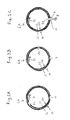
- the reference numeral 14 at the shown straight dashline indicates the location of the rectangular straight slit passage through the circumferential outer cylinder wall 12 of the outer cylinder 10. This rectangular straight slit passage 14 is located at the bottom of the outer cylinder, see also Figs.
- FIG. 1 the reference numeral 24 at the shown curved dashline indicates the location of the helical slit passage through the circumferential inner cylinder wall 22 of the inner cylinder 20, see also Figs. 2A-2C .
- the air supplier 18 which is shown highly schematically in Fig. 1 , supplies air into the interior of the air duct 6A.
- the row 3A of plants 2 experiences a number of simultaneously occurring air spurts 8 (two of which are shown in Fig. 1 ), which are travelling in the shown direction 30.
- the air duct 6A has a length of 85 m in the longitudinal air duct direction 7.
- the outside diameter of the outer cylinder 10 is 0.45 m.
- the helical slit passage 24 through circumferential inner cylinder wall 22 has a pitch of 17 m, which means there are 5 helical revolutions over the length of 85 m. Accordingly, there are five exhaust locations 9 where simultaneous air exhaust occurs.
- the straight slit passage 14 through circumferential outer cylinder wall 12 has a width of 0.08 m.
- each exhaust location 9 there occurs air exhaust in a range of 0.4 m as measured in the longitudinal air duct direction 7.
- the rotation speed of inner cylinder 20 relative to outer cylinder 10 is 0.5 rpm.
- the air exhaust speed at the exhaust locations 9 is 5 m/s.
- the air velocity will have been dropped into roughly about 2 m/s This means that every individual plant 2 in the row 3A will experience every 2 minutes a spurt of air 8 of about 2 m/s, which spurt of air lasts about 3 s.
- the outer passage structure 14 and the inner passage structure 24 are each elongated continuous passage structures.
- Fig. 3 serves to illustrate that instead of such elongated continuous passage structures, also discrete passage structures are possible. That is, in Fig. 3 the reference numbers 114-122 indicate the application of a number of discrete circular passages 114-122 instead of the straight slit passage 14 in Figs. 1 , 2 . Similarly, the reference numbers 124-132 indicate the application of a number of discrete circular passages 124-132 instead of the helical slit passage 24 in Figs. 1 , 2 . Note that the lastmentioned discrete circular passages 124-132 in Fig. 3 are helically aligned according to a similar helical direction as in Fig. 1 (this helical direction has been indicated in Fig. 3 by a similar curved dash line as in Fig. 1 ).
- Fig. 4 shows that the ventilation and/or circulation system 5 comprises at least the additional air ducts 6B, 6C, 6D, which are similar to and parallel to air duct 6A, and which are similarly arranged above additional plant rows 3B, 3C, 3D, which are similar to and parallel to plant row 3A.
- different traveling directions 30 of the exhaust locations 9 may be applied for the different air ducts 6A, 6B, 6C, 6D, respectively.
- the traveling directions 30 for the air ducts 6A and 6C may be chosen to be mutually the same, but opposite to the traveling directions 30 for the air ducts 6B and 6D.
- Fig. 5 serves to illustrate that it is also possible that one air duct may serve more than one parallel rows of plants. In the shown example, this may e.g. be realized by using two separate straight slit passages through the circumferential outer cylinder wall of one air duct.
- Fig. 5 makes clear that each of the air ducts 206A and 206A may have two parallel and mutually spaced straight slit passages similar to the straight slit passage 14 of Figs. 1 , 2 .
- this may e.g. be realized by using two separate helically configured inner passage structures through the circumferential inner cylinder wall of one air duct, wherein the pitch directions of these two separate helically configured inner passage structures are mutually opposite.
Landscapes
- Life Sciences & Earth Sciences (AREA)
- Environmental Sciences (AREA)
- Greenhouses (AREA)
Abstract
In a greenhouse (1) air is mixed around plants (2) by means of a ventilation and/or circulation system (5), which comprises an air duct (6A). The air duct comprises a variable passage structure (14, 24) through an outer circumferential wall structure (12, 22) of the air duct. Said mixing is performed in that via said variable passage structure air is exhausted out of the interior of the air duct and in the direction of a row of plants. Each individual plant in the row of plants experiences intermittent spurts of air (8), which spurts of air are caused by exhaust of air from time-dependently varying different exhaust locations (9) of the variable passage structure, while said time-dependently varying different exhaust locations are traveling (30) in the longitudinal air duct direction (7) for exposing all individual plants along the longitudinal row direction (4) to said spurts of air (8).
Description
- The invention relates to mixing air around plants in a greenhouse. More in particular the invention relates to reducing the local humidity in the air directly adjacent to leaves of the plants, by transporting moisture from the boundary layers around the leaves towards the surrounding areas in the greenhouse. The reason for this kind of air mixing is that a too high humidity in said boundary layers increases the risk of plant diseases.
- Commonly, reducing the humidity in said boundary layers is done by directing a continuous and moderate ventilation and/or circulation flow towards the plants. However, a drawback of this commonly applied ventilation and/or circulation method is that for many greenhouse configurations the lowest ventilation and/or circulation flow level which is still sufficient for avoiding said risk of plant diseases unfortunately already exceeds a critical flow level at which there arises local plant damage due to dehydration. Such local plant damage appears as dead, brown leaves and often results in poor quality of the greenhouse products.
- It is an object of the present invention to provide an efficient solution according to which the humidity in the boundary layers around the leaves of plants in a greenhouse is reduced sufficiently for preventing said plant diseases, while at the same time said local plant damage due to dehydration is prevented.
- For that purpose the present invention provides a method according to the appended independent claim 1. Furthermore, the present invention provides a ventilation and/or circulation system according to the appended
independent claim 2. Preferable embodiments of the invention are provided by the appended dependent claims 3-6. The method according to the appended independent claim 1 can be perfomed by means of a ventilation and/or circulation system according to any one of the appended dependent claims 2-5, and in a greenhouse according to the appended dependent claim 6. - Hence, the invention provides a method of mixing air around plants in a greenhouse, wherein:
- said plants are arranged in at least one row of plants, which row of plants has a longitudinal row direction;
- said mixing is performed by means of a ventilation and/or circulation system, which comprises at least one air duct, which air duct has a longitudinal air duct direction;
- said air duct comprises a variable passage structure through an outer circumferential wall structure of the air duct, wherein said variable passage structure is extending in said longitudinal air duct direction; and
- said mixing is performed in that via said variable passage structure air is exhausted out of the interior of the air duct and in the direction of the row of plants, in such manner that each individual plant in the row of plants experiences intermittent spurts of air, which spurts of air are caused by exhaust of air from time-dependently varying different exhaust locations of said variable passage structure, while said time-dependently varying different exhaust locations are traveling in said longitudinal air duct direction for exposing all individual plants of the row of plants along said longitudinal row direction to said spurts of air.
- Furthermore, the invention provides a ventilation and/or circulation system for mixing air around plants in a greenhouse, which ventilation and/or circulation system comprises at least one air duct, having a longitudinal air duct direction, which air duct comprises a variable passage structure through an outer circumferential wall structure of the air duct, which variable passage structure is extending in said longitudinal air duct direction, and wherein the ventilation and/or circulation system is configured, arranged and effective to exhaust air out of the interior of the air duct via time-dependently varying different exhaust locations of said variable passage structure, while said time-dependently varying different exhaust locations are traveling in said longitudinal air duct direction.
- Accordingly, an important working principle used in the present invention is that exposing plants to intermittent spurts of air, as opposed to exposing plants to the commonly used continuous ventilation and/or circulation flow, allows for providing sufficiently effective ventilation and/or circulation for avoiding said risk of plant diseases, while not yet exceeding critical flow conditions where local plant damage due to dehydration would arise. Without wishing to be bound by any theory, it is believed that, every time in-between two spurts of air, the leaves are able to recover from a probable initial stage of dehydration (if any) caused by the spurt of air. In every interval in-between two spurts of air the humidity in the boundary layers is built up again, until the next spurt of air, and so forth. This working principle more or less relates to what happens in nature. That is, plants in open nature are exposed to more or less intermittent gusts of winds, which blow away moisture from the boundary layers around the plant leaves.
- In addition to the above-explained effective working principle, the invention provides the further important working principle which relates to said traveling behaviour in said longitudinal air duct direction of the time-dependently varying different exhaust locations of the spurts of air. This traveling behaviour makes the invention a very efficient solution for treating a large amount of plants in a greenhouse. Also this working principle more or less relates to what happens in nature. That is, a gust of wind often hits plants one after the other, e.g. producing a "traveling wave" through a field of plants.
- A preferable embodiment of a ventilation and/or circulation system according to the invention is defined in that:
- said air duct comprises an outer cylinder and an inner cylinder, having a circumferential outer cylinder wall and a circumferential inner cylinder wall, respectively;
- the inner cylinder is co-axially mounted within the outer cylinder;
- the outer circumferential wall structure of the air duct comprises a double wall formed by the circumferential outer cylinder wall and the circumferential inner cylinder wall;
- the outer cylinder and the inner cylinder are rotatable relative to one another around their common center line;
- said variable passage structure of said outer circumferential wall structure of the air duct comprises an outer passage structure through the circumferential outer cylinder wall and an inner passage structure through the circumferential inner cylinder wall;
- each of said outer passage structure and said inner passage structure is extending in said longitudinal air duct direction; and
- said outer passage structure and said inner passage structure are configured, arranged and effective to provide said time-dependently varying different exhaust locations of said variable passage structure by means of time-dependently varying different air connections between said outer passage structure and said inner passage structure during said rotation relative to one another around said common center line.
- This preferable embodiment is very efficient in that it allows for realizing the traveling of the spurts of air by means of a simple rotative motion and a continuous air supply to the interior of the air duct.
- It is noted that the relative rotation between the outer cylinder and the inner cylinder can be realized in that the outer cylinder is fixed relative to the greenhouse while the inner cylinder is rotating relative to the greenhouse, or in that the inner cylinder is fixed relative to the greenhouse while the outer cylinder is rotating relative to the greenhouse, or even in that both the outer cylinder and the inner cylinder are rotating relative to the greenhouse.
- In a further preferable embodiment of a ventilation and/or circulation system according to the invention:
- said outer passage structure comprises a helical outer passage structure, which is extending in a helical direction of said outer cylinder; and/or
- said inner passage structure comprises a helical inner passage structure, which is extending in a helical direction of said inner cylinder.
- The application of at least one such a helical outer passage structure and/or of at least one such a helical inner passage structure makes the ventilation and/or circulation system very effective and reliable.
- In a yet further preferable embodiment of a ventilation and/or circulation system according to the invention that said outer circumferential wall structure of the air duct is transparent for light. This allows the plants in the greenhouse to receive light through said outer circumferential wall structure of the air duct.
- The abovementioned aspects and other aspects of the invention will be apparent from and elucidated with reference to the embodiments described hereinafter by way of non-limiting examples only and with reference to the schematic figures in the enclosed drawing.
-
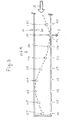
Fig. 1 shows, in longitudinal cross-sectional view, an example of an embodiment of a ventilation and/or circulation system according to the invention, while carrying out an example of an embodiment of a method according to the invention in a greenhouse. -
Fig. 2A shows the air duct of the ventilation and/or circulation system ofFig. 1 in a transverse cross-sectional plane, which is indicated by the arrow II-A inFig. 1 , wherein the view ofFig. 2A is taken in the direction of the arrow II-A. -
Fig. 2B shows the air duct of the ventilation and/or circulation system ofFig. 1 in a transverse cross-sectional plane, which is indicated by the arrow II-B inFig. 1 , wherein the view ofFig. 2B is taken in the direction of the arrow II-B. -
Fig. 2C shows the air duct of the ventilation and/or circulation system ofFig. 1 in a transverse cross-sectional plane, which is indicated by the arrow II-C inFig. 1 , wherein the view ofFig. 2C is taken in the direction of the arrow II-C. -
Fig. 3 shows, in a similar longitudinal cross-sectional view as that ofFig. 1 , an example of an embodiment of an alternative air duct, which can be used according to the invention. -
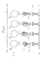
Fig. 4 shows the greenhouse ofFig. 1 in a transverse cross-sectional plane, which is parallel to the transverse cross-sectional planes ofFigs. 2A, 2B, 2C . -
Fig. 5 shows, in a similar transverse cross-sectional view as that ofFig. 4 , an example of an embodiment of a further alternative air duct, which can be used according to the invention. - The reference signs used in the abovementioned
Figs. 1-5 are referring to the abovementioned parts and aspects of the invention, as well as to related parts and aspects, in the following manner. - 1
- greenhouse
- 2
- plant
- 3A, 3B, 3C, 3D
- rows of plants
- 4
- longitudinal row direction
- 5
- ventilation and/or circulation system
- 6A, 6B, 6C, 6D; 106A; 206A, 206B
- air ducts
- 7
- longitudinal air duct direction
- 8
- spurt of air
- 9
- exhaust location
- 10
- outer cylinder
- 11
- end wall of
outer cylinder 10 - 12
- circumferential outer cylinder wall
- 14
- straight slit passage through circumferential
outer cylinder wall 12 - 114-122
- straightly in-line circular passages
- 18
- air supplier
- 20
- inner cylinder
- 21
- end wall of
inner cylinder 20 - 22
- circumferential inner cylinder wall
- 24
- helical slit passage through circumferential
inner cylinder wall 22 - 124-132
- helically aligned circular passages
- 30
- traveling direction of exhaust location 9
- 31
- rotation direction of
inner cylinder 20 relative toouter cylinder 10 - It is noted that, where the same reference signs are used throughout different ones of the abovementioned
Figs. 1-5 , these reference signs denote the same or similar parts or aspects. -
Fig. 1 shows theair duct 6A of the ventilation and/or circulation system 5, wherein theair duct 6A is located above the row 3A ofplants 2. The longitudinalair duct direction 7 ofair duct 6A is parallel to thelongitudinal row direction 4 of the row 3A. In the shown example, theair duct 6A comprises theouter cylinder 10 and theinner cylinder 20, wherein theouter cylinder 10 is fixed relative to the greenhouse 1, while theinner cylinder 20 is rotatable relative to the greenhouse 1. InFig. 1 , thereference numeral 14 at the shown straight dashline indicates the location of the rectangular straight slit passage through the circumferentialouter cylinder wall 12 of theouter cylinder 10. This rectangularstraight slit passage 14 is located at the bottom of the outer cylinder, see alsoFigs. 2A-2C . Furthermore, inFig. 1 thereference numeral 24 at the shown curved dashline indicates the location of the helical slit passage through the circumferentialinner cylinder wall 22 of theinner cylinder 20, see alsoFigs. 2A-2C . - In use, the
air supplier 18, which is shown highly schematically inFig. 1 , supplies air into the interior of theair duct 6A. As a result, the row 3A ofplants 2 experiences a number of simultaneously occurring air spurts 8 (two of which are shown inFig. 1 ), which are travelling in the showndirection 30. - To illustratively show just an arbitrary rough example of a possible practical use of such a ventilation and/or circulation system 5 in a greenhouse 1, the following approximate example parameters are given. The
air duct 6A has a length of 85 m in the longitudinalair duct direction 7. The outside diameter of theouter cylinder 10 is 0.45 m. Thehelical slit passage 24 through circumferentialinner cylinder wall 22 has a pitch of 17 m, which means there are 5 helical revolutions over the length of 85 m. Accordingly, there are five exhaust locations 9 where simultaneous air exhaust occurs. Thestraight slit passage 14 through circumferentialouter cylinder wall 12 has a width of 0.08 m. At each exhaust location 9 there occurs air exhaust in a range of 0.4 m as measured in the longitudinalair duct direction 7. At average load of the system, the rotation speed ofinner cylinder 20 relative toouter cylinder 10 is 0.5 rpm. Then, the air exhaust speed at the exhaust locations 9 is 5 m/s. At the location of aplant 2 the air velocity will have been dropped into roughly about 2 m/s This means that everyindividual plant 2 in the row 3A will experience every 2 minutes a spurt ofair 8 of about 2 m/s, which spurt of air lasts about 3 s. - In the example of
Figs. 1 and2 , theouter passage structure 14 and theinner passage structure 24 are each elongated continuous passage structures.Fig. 3 serves to illustrate that instead of such elongated continuous passage structures, also discrete passage structures are possible. That is, inFig. 3 the reference numbers 114-122 indicate the application of a number of discrete circular passages 114-122 instead of thestraight slit passage 14 inFigs. 1 ,2 . Similarly, the reference numbers 124-132 indicate the application of a number of discrete circular passages 124-132 instead of thehelical slit passage 24 inFigs. 1 ,2 . Note that the lastmentioned discrete circular passages 124-132 inFig. 3 are helically aligned according to a similar helical direction as inFig. 1 (this helical direction has been indicated inFig. 3 by a similar curved dash line as inFig. 1 ). -
Fig. 4 shows that the ventilation and/or circulation system 5 comprises at least theadditional air ducts air duct 6A, and which are similarly arranged aboveadditional plant rows directions 30 of the exhaust locations 9 may be applied for thedifferent air ducts directions 30 for theair ducts 6A and 6C may be chosen to be mutually the same, but opposite to the travelingdirections 30 for theair ducts -
Fig. 5 serves to illustrate that it is also possible that one air duct may serve more than one parallel rows of plants. In the shown example, this may e.g. be realized by using two separate straight slit passages through the circumferential outer cylinder wall of one air duct.Fig. 5 makes clear that each of the air ducts 206A and 206A may have two parallel and mutually spaced straight slit passages similar to thestraight slit passage 14 ofFigs. 1 ,2 . It is noted that, in case one would wish to expose theplant rows 3A and 3C inFig. 5 to travelingdirections 30 which are mutually opposite to those to which theplant rows 3B and 3D are exposed (similar to the option discussed above in relation toFig. 4 ), this may e.g. be realized by using two separate helically configured inner passage structures through the circumferential inner cylinder wall of one air duct, wherein the pitch directions of these two separate helically configured inner passage structures are mutually opposite. - While the invention has been described and illustrated in detail in the foregoing description and in the drawing figures, such description and illustration are to be considered exemplary and/or illustrative and not restrictive; the invention is not limited to the disclosed embodiments.
- Other variations to the disclosed embodiments can be understood and effected by those skilled in the art in practicing the claimed invention, from a study of the drawings, the disclosure, and the appended claims. In the claims, the word "comprising" does not exclude other elements or steps, and the indefinite article "a" or "an" does not exclude a plurality. A single other unit may fulfill the functions of several items recited in the claims. For the purpose of clarity and a concise description, features are disclosed herein as part of the same or separate embodiments, however, it will be appreciated that the scope of the invention may include embodiments having combinations of all or some of the features disclosed. Any reference signs in the claims should not be construed as limiting the scope.
Claims (6)
- Method of mixing air around plants (2) in a greenhouse (1), wherein:- said plants are arranged in at least one row of plants (3A, 3B, 3C, 3D), which row (3A) of plants has a longitudinal row direction (4);- said mixing is performed by means of a ventilation and/or circulation system (5), which comprises at least one air duct (6A, 6B, 6C, 6D; 106A; 206A, 206B), which air duct (6A) has a longitudinal air duct direction (7);- said air duct comprises a variable passage structure (14, 24; 114-122, 124-132) through an outer circumferential wall structure (12, 22) of the air duct, wherein said variable passage structure is extending in said longitudinal air duct direction; and- said mixing is performed in that via said variable passage structure air is exhausted out of the interior of the air duct and in the direction of the row of plants, in such manner that each individual plant in the row of plants experiences intermittent spurts of air (8), which spurts of air are caused by exhaust of air from time-dependently varying different exhaust locations (9) of said variable passage structure, while said time-dependently varying different exhaust locations are traveling (30) in said longitudinal air duct direction (7) for exposing all individual plants of the row of plants along said longitudinal row direction (4) to said spurts of air (8).
- Ventilation and/or circulation system for mixing air around plants (2) in a greenhouse (1), which ventilation and/or circulation system (5) comprises at least one air duct (6A, 6B, 6C, 6D; 106A; 206A, 206B), having a longitudinal air duct direction (7), which air duct comprises a variable passage structure (14, 24; 114-122, 124-132) through an outer circumferential wall structure (12, 22) of the air duct, which variable passage structure is extending in said longitudinal air duct direction, and wherein the ventilation and/or circulation system is configured, arranged and effective to exhaust air out of the interior of the air duct via time-dependently varying different exhaust locations (9) of said variable passage structure, while said time-dependently varying different exhaust locations are traveling (30) in said longitudinal air duct direction.
- Ventilation and/or circulation system according to claim 2, wherein:- said air duct (6A) comprises an outer cylinder (10) and an inner cylinder (20), having a circumferential outer cylinder wall (12) and a circumferential inner cylinder wall (22), respectively;- the inner cylinder is co-axially mounted within the outer cylinder;- the outer circumferential wall structure of the air duct comprises a double wall formed by the circumferential outer cylinder wall (12) and the circumferential inner cylinder wall (22);- the outer cylinder (10) and the inner cylinder (20) are rotatable (31) relative to one another around their common center line;- said variable passage structure of said outer circumferential wall structure of the air duct comprises an outer passage structure (14; 114-122) through the circumferential outer cylinder wall (12) and an inner passage structure (24; 124-132) through the circumferential inner cylinder wall (22);- each of said outer passage structure and said inner passage structure is extending in said longitudinal air duct direction (7); and- said outer passage structure and said inner passage structure are configured, arranged and effective to provide said time-dependently varying different exhaust locations (9) of said variable passage structure by means of time-dependently varying different air connections between said outer passage structure and said inner passage structure during said rotation (31) relative to one another around said common center line.
- Ventilation and/or circulation system according to claim 3, wherein:- said outer passage structure comprises a helical outer passage structure, which is extending in a helical direction of said outer cylinder; and/or- said inner passage structure comprises a helical inner passage structure (24; 124-132), which is extending in a helical direction of said inner cylinder (20).
- Ventilation and/or circulation system according to any one of claims 2-4, wherein said outer circumferential wall structure (12, 22) of the air duct (6A) is transparent for light.
- Greenhouse comprising a ventilation and/or circulation system (5) according to any one of claims 2-5.
Priority Applications (2)
| Application Number | Priority Date | Filing Date | Title |
|---|---|---|---|
| EP15183510.5A EP3138388A1 (en) | 2015-09-02 | 2015-09-02 | Method and ventilation and/or circulation system for mixing air around plants in a greenhouse |
| PCT/NL2016/050610 WO2017039446A1 (en) | 2015-09-02 | 2016-09-01 | Method and ventilation and/or circulation system for mixing air around plants in a greenhouse |
Applications Claiming Priority (1)
| Application Number | Priority Date | Filing Date | Title |
|---|---|---|---|
| EP15183510.5A EP3138388A1 (en) | 2015-09-02 | 2015-09-02 | Method and ventilation and/or circulation system for mixing air around plants in a greenhouse |
Publications (1)
| Publication Number | Publication Date |
|---|---|
| EP3138388A1 true EP3138388A1 (en) | 2017-03-08 |
Family
ID=54056117
Family Applications (1)
| Application Number | Title | Priority Date | Filing Date |
|---|---|---|---|
| EP15183510.5A Withdrawn EP3138388A1 (en) | 2015-09-02 | 2015-09-02 | Method and ventilation and/or circulation system for mixing air around plants in a greenhouse |
Country Status (2)
| Country | Link |
|---|---|
| EP (1) | EP3138388A1 (en) |
| WO (1) | WO2017039446A1 (en) |
Families Citing this family (1)
| Publication number | Priority date | Publication date | Assignee | Title |
|---|---|---|---|---|
| CN116546880A (en) * | 2020-08-26 | 2023-08-04 | Hgci股份有限公司 | Air conveying system for plant planting frame |
Citations (4)
| Publication number | Priority date | Publication date | Assignee | Title |
|---|---|---|---|---|
| US3474720A (en) * | 1968-03-01 | 1969-10-28 | Modine Mfg Co | Apparatus for conditioning air |
| NL8200360A (en) * | 1982-02-01 | 1983-09-01 | Priva Handel Bv | Greenhouse air circulation system - has raised fan with long horizontal throw and second fan directing outside air at inlet of first fan |
| WO2011028100A2 (en) * | 2009-09-03 | 2011-03-10 | Priva Bv | Arrangement for even distribution of gaseous material in a spatial area |
| NL2009917C2 (en) * | 2012-11-30 | 2014-06-04 | Wilk Van Der Sande B V | VENTILATION TUBE FOR A GREENHOUSE FITTED WITH AN INSULATING AIR ROOM. |
-
2015
- 2015-09-02 EP EP15183510.5A patent/EP3138388A1/en not_active Withdrawn
-
2016
- 2016-09-01 WO PCT/NL2016/050610 patent/WO2017039446A1/en not_active Ceased
Patent Citations (4)
| Publication number | Priority date | Publication date | Assignee | Title |
|---|---|---|---|---|
| US3474720A (en) * | 1968-03-01 | 1969-10-28 | Modine Mfg Co | Apparatus for conditioning air |
| NL8200360A (en) * | 1982-02-01 | 1983-09-01 | Priva Handel Bv | Greenhouse air circulation system - has raised fan with long horizontal throw and second fan directing outside air at inlet of first fan |
| WO2011028100A2 (en) * | 2009-09-03 | 2011-03-10 | Priva Bv | Arrangement for even distribution of gaseous material in a spatial area |
| NL2009917C2 (en) * | 2012-11-30 | 2014-06-04 | Wilk Van Der Sande B V | VENTILATION TUBE FOR A GREENHOUSE FITTED WITH AN INSULATING AIR ROOM. |
Also Published As
| Publication number | Publication date |
|---|---|
| WO2017039446A1 (en) | 2017-03-09 |
Similar Documents
| Publication | Publication Date | Title |
|---|---|---|
| EP3407837B1 (en) | Helical bone graft containment cage | |
| EP3534690B1 (en) | Climatically sealed climate-controlled cell for indoor cultivation of plants | |
| DE102015226575B4 (en) | fan means | |
| ES2184571B1 (en) | FAN OF CROSSED CURRENTS OF AN AIR CONDITIONING DEVICE AND PROCEDURE FOR MANUFACTURING. | |
| EP2815130A2 (en) | Diffusor, ventilator having such a diffusor, and device having such ventilators | |
| RU2008135271A (en) | TURBINE ROTOR SYSTEM AND DEVICE | |
| RU2013103432A (en) | TURBINE SHOVEL (OPTIONS) AND METHOD FOR FILM COOLING OF A TURBINE SHOVEL | |
| US9567732B2 (en) | Methods, systems and apparatus for a wind turbine and water collection system | |
| EP2521859B1 (en) | Wind power plant | |
| CN104450166A (en) | Tung tree husking device | |
| WO2017039446A1 (en) | Method and ventilation and/or circulation system for mixing air around plants in a greenhouse | |
| CN106968977B (en) | A kind of self-cleaning power equipment blower | |
| BR102017003648A2 (en) | ELEMENT AND ARRANGEMENT OF AIR PURIFICATION. | |
| AR108366A1 (en) | THE METHOD AND PLANT FOR PROCESSING CHEESE OF SPINNING PASTA, AND THE CORRESPONDING MOLDING MACHINE | |
| JP2020532320A5 (en) | ||
| PL237283B1 (en) | Multi-segmented wind turbine | |
| EP2727642A1 (en) | Dehumidifying device for a gaseous medium | |
| JP2007181434A (en) | Ventilation device in chicken cage unit | |
| DE19734802C1 (en) | Air suction turbine wheel for food treatment chamber has vane | |
| RU155147U1 (en) | WIND POWER PLANT | |
| ES2911671T3 (en) | Air distribution device, in particular for a public transport vehicle | |
| CN203646103U (en) | Paddy thresher | |
| DE102017004714A1 (en) | Savonius turbine | |
| US20160047600A1 (en) | Grain drying tower of parallel and sinuous flow through reverse crossed air flow and radial air flow in oblique "z" form | |
| KR101538765B1 (en) | Water purification device of the reservoir |
Legal Events
| Date | Code | Title | Description |
|---|---|---|---|
| PUAI | Public reference made under article 153(3) epc to a published international application that has entered the european phase |
Free format text: ORIGINAL CODE: 0009012 |
|
| AK | Designated contracting states |
Kind code of ref document: A1 Designated state(s): AL AT BE BG CH CY CZ DE DK EE ES FI FR GB GR HR HU IE IS IT LI LT LU LV MC MK MT NL NO PL PT RO RS SE SI SK SM TR |
|
| AX | Request for extension of the european patent |
Extension state: BA ME |
|
| RIN1 | Information on inventor provided before grant (corrected) |
Inventor name: KNOLL, BASTIAAN |
|
| STAA | Information on the status of an ep patent application or granted ep patent |
Free format text: STATUS: THE APPLICATION IS DEEMED TO BE WITHDRAWN |
|
| 18D | Application deemed to be withdrawn |
Effective date: 20170909 |