EP3137985B1 - Method and system to create a rendering pipeline - Google Patents
Method and system to create a rendering pipeline Download PDFInfo
- Publication number
- EP3137985B1 EP3137985B1 EP15730892.5A EP15730892A EP3137985B1 EP 3137985 B1 EP3137985 B1 EP 3137985B1 EP 15730892 A EP15730892 A EP 15730892A EP 3137985 B1 EP3137985 B1 EP 3137985B1
- Authority
- EP
- European Patent Office
- Prior art keywords
- state
- gpu
- pipeline
- compiled
- application
- Prior art date
- Legal status (The legal status is an assumption and is not a legal conclusion. Google has not performed a legal analysis and makes no representation as to the accuracy of the status listed.)
- Active
Links
Images


Classifications
-
- G—PHYSICS
- G06—COMPUTING OR CALCULATING; COUNTING
- G06T—IMAGE DATA PROCESSING OR GENERATION, IN GENERAL
- G06T1/00—General purpose image data processing
- G06T1/20—Processor architectures; Processor configuration, e.g. pipelining
-
- G—PHYSICS
- G06—COMPUTING OR CALCULATING; COUNTING
- G06F—ELECTRIC DIGITAL DATA PROCESSING
- G06F3/00—Input arrangements for transferring data to be processed into a form capable of being handled by the computer; Output arrangements for transferring data from processing unit to output unit, e.g. interface arrangements
- G06F3/14—Digital output to display device ; Cooperation and interconnection of the display device with other functional units
-
- G—PHYSICS
- G06—COMPUTING OR CALCULATING; COUNTING
- G06F—ELECTRIC DIGITAL DATA PROCESSING
- G06F8/00—Arrangements for software engineering
- G06F8/40—Transformation of program code
- G06F8/41—Compilation
- G06F8/47—Retargetable compilers
-
- G—PHYSICS
- G06—COMPUTING OR CALCULATING; COUNTING
- G06T—IMAGE DATA PROCESSING OR GENERATION, IN GENERAL
- G06T15/00—Three-dimensional [3D] image rendering
- G06T15/50—Lighting effects
- G06T15/80—Shading
-
- G—PHYSICS
- G06—COMPUTING OR CALCULATING; COUNTING
- G06T—IMAGE DATA PROCESSING OR GENERATION, IN GENERAL
- G06T2200/00—Indexing scheme for image data processing or generation, in general
- G06T2200/28—Indexing scheme for image data processing or generation, in general involving image processing hardware
Definitions
- This disclosure relates generally to the field of computer programming. More particularly, but not by way of limitation, it relates to techniques for programming graphical and computational applications to execute on a variety of graphical and computational processors.
- Computers and other computational devices typically have at least one programmable processing element that is generally known as a central processing unit (CPU). They frequently also have other programmable processors that are used for specialized processing of various types, such as graphics processing operations, hence are typically called graphics processing units (GPUs). GPUs generally comprise multiple cores or processing elements designed for executing the same instruction on parallel data streams, making them more effective than general-purpose CPUs for algorithms in which processing of large blocks of data is done in parallel. In general, a CPU functions as the host and hands-off specialized parallel tasks to the GPUs.
- CPU central processing unit
- GPUs graphics processing units
- OpenGL TM OpenGL TM . OpenGL focuses on using the GPU for graphics processing and provides APIs for rendering 2D and 3D graphics.
- OpenGL offers a C-like development environment in which users can create applications to run on various different types of CPUs, GPUs, digital signal processors (DSPs), and other processors.
- OpenGL also provides a compiler and a runtime environment in which code can be compiled and executed within a heterogeneous computing system.
- developers can use a single, unified language to target all of the processors for which an OpenGL driver is available. This is done by presenting the developer with an abstract platform model and application programming interface (API) that conceptualizes all of these architectures in a similar way, as well as an execution model supporting data and task parallelism across heterogeneous architectures.
- API application programming interface
- an OpenGL program When an OpenGL program is executed, a series of API calls configure the system for execution, an embedded compiler compiles the OpenGL code, and the runtime asynchronously coordinates execution between parallel tasks.
- a typical OpenGL-based system runs source code through an embedded compiler on the end-user system to generate executable code for a target GPU available on that system. Then, the executable code, or portions of the executable code, are sent to the target GPU and are executed.
- this approach particularly the compiling step, may take too long for some types of applications, such as graphics-intensive games.
- OpenGL itself may be considered as a state machine, with each command potentially resulting in a state change that requires the generation and/or compilation of new GPU code. This arises from the fact that certain GPU functions rely on dedicated circuitry within the GPU, while others require use of the programmable features of the GPU. Depending on the particular GPU hardware being used, these types of state changes can be very expensive from a computation time perspective. Additionally, in recent years, evolution of GPU hardware has outpaced evolution of OpenGL, such that, in some sense, OpenGL APIs are mismatched to the hardware environment in which the programs will run. The result is that a developer may inadvertently be writing code that is particularly inefficient for at least some hardware on which it will run.
- Direct3D 12 graphics API contains a number of rendering pipeline features which aim to improve the efficiency of certain graphics algorithms through improved utilization of GPU hardware.
- Ivan Navraev "Microsoft Introduction to Direct3D 12", 4 April 2014 (Retrieved from the Internet: https://www.slideshare.net/DevCentralAM D/introduction-to-dx12-by-ivan-nevraev ) is a presentation previewing the Direct3D 12 API, and in particular, the pipeline state optimization performed by Direct3D 12.
- WO 2012/082423 A1 discloses a system for access to accelerated processing device compute resources to user mode applications.
- the functionality disclosed allows user mode applications to provide commands to an accelerated processing device without the need for kernel mode transitions in order to access a unified ring buffer. Instead, applications are each provided with their own buffers, which the accelerated processing device hardware can access to process commands. With full operating system support, user mode applications are able to utilize the accelerated processing device in much the same way as a CPU.
- US 2011/063296 A1 discloses a method for storing processed data within buffer objects stored in buffer object memory from within shader engines executing on a GPU.
- the method comprises the steps of receiving a stream of one or more shading program commands via a graphics driver, executing, within a shader engine, at least one of the one or more shading program commands to generate processed data, determining from the stream of one or more shading program commands an address associated with a first data object stored within the buffer memory, and storing, from within the shader engine, the processed data in the first data object stored within the buffer memory.
- US 2008/001952 A1 discloses a system for binding resources to particular slots associated with shaders in a graphics pipeline.
- Resource dependencies between resources being utilized by each shader can be determined, and, based on these resource dependencies, common resource/slot associations can be computed.
- Each common resource/slot association identifies a particular one of the resources to be associated with a particular one of the slots.
- US 2013/265309 A1 discloses a process for rendering graphics that includes performing, with a hardware shading unit of a graphics processing unit (GPU) designated for vertex shading, vertex shading operations to shade input vertices so as to output vertex shaded vertices, wherein the hardware unit is configured to receive a single vertex as an input and generate a single vertex as an output.
- the process also includes performing, with the hardware shading unit of the GPU, a geometry shading operation to generate one or more new vertices based on one or more of the vertex shaded vertices, wherein the geometry shading operation operates on at least one of the one or more vertex shaded vertices to output the one or more new vertices.
- the invention is defined by a method according to claim 1, a system according to claim 8 and a non-transitory computer readable medium according to claim 14.
- An innovative GPU framework and related APIs present more accurate representations of the target hardware so that the distinctions between the fixed-function and programmable features of the GPU are perceived by a developer.
- the definitional components requiring programmable GPU features can be compiled only once and reused repeatedly as needed.
- the state changes correspond to the state changes made on the hardware.
- the creation of these immutable objects prevents a developer from inadvertently changing portions of the program or object that cause it to behave differently than intended.
- a computer system can refer to a single computer or a plurality of computers working together to perform the function described as being performed on or by a computer system.
- a machine-readable medium can refer to a single physical medium or a plurality of media that may together contain the indicated information stored thereon.
- a processor can refer to a single processing element or a plurality of processing elements, implemented either on a single chip or on multiple processing chips.
- a developer can create and submit source code in the unified programming interface 110, which can be a GPU-specific programming language.
- the unified programming interface 110 may provide a single framework for developers to write their GPU programing code on. Once the code is written, it may be directed to a compiler 115, which can be a compiler for a GPU-specific programming language, and which may parse the source code and generate a machine-independent programming language-independent representation. The result may then be distributed from the developer computer system 100 to application 120.
- Application 120 can contain the shader code in a device-independent form (in addition to everything else the application contains: CPU code, text, other resources, etc.).
- the application 120 may be delivered to the target machine 105 in any desired manner, including electronic transport over a network and physical transport of machine-readable media. This generally involves delivery of the application 120 to a server (not shown in FIG. 1 ) from which the target system 105 may obtain the application 120.
- the application 120 may be bundled with other data, such as run-time libraries, installers, etc. that may be useful for the installation of the application 120 on the target system 105. In some situations, the application 120 may be provided as part of a larger package of software.
- one action performed by the application can be creation of a collection of pipeline objects 155 that may include state information 125, fragment shaders 130, and vertex shaders 135, the application may be compiled by an embedded GPU compiler 145 that compiles the representation provided by the compiler 115 into native binary code for the GPU 150.
- the compiled native code may be cached in cache 140 or stored elsewhere in the target system 105 to improve performance if the same pipeline is recreated later, such as during future launches of the application.
- the GPU 150 may execute the native binary code, performing the graphics and compute kernels for data parallel operations.
- FIG. 2 a block diagram illustrates a computer system 200 that can serve as the developer system 100 according to one embodiment. While FIG. 2 illustrates various components of a computer system, it is not intended to represent any particular architecture or manner of interconnecting the components as such details are not germane to the present disclosure.
- Network computers and other data processing systems for example, handheld computers, personal digital assistants (PDAs), cellular telephones, entertainment systems, consumer electronic devices, etc.
- PDAs personal digital assistants
- cellular telephones for example, cellular telephones, entertainment systems, consumer electronic devices, etc.
- consumer electronic devices etc.
- the computer system 200 which is a form of a data processing system, includes a bus 222 which is coupled to a microprocessor(s) 216, which may be CPUs and/or GPUs, a memory 212, which may include one or both of a volatile read/write random access memory (RAM) and a read-only memory (ROM), and a non-volatile storage device 214.
- the microprocessor(s) 216 may retrieve instructions from the memory 212 and the storage device 214 and execute the instructions using cache 218 to perform operations described above.
- the link 222 interconnects these various components together and also interconnects these components 216, 218, 212, and 214 to a display controller 206 and display device 220 and to peripheral devices such as input/output (I/O) devices 204 which may be mice, keyboards, touch screens, modems, network interfaces, printers and other devices which are well known in the art.
- I/O input/output
- the input/output devices 204 are coupled to the system through input/output controllers 202.
- volatile RAM is included in memory 212
- the RAM is typically implemented as dynamic RAM (DRAM), which requires power continually in order to refresh or maintain the data in the memory.
- DRAM dynamic RAM
- the display controller 206 and display device 220 may optionally include one or more GPUs to process display data.
- the storage device 214 is typically a magnetic hard drive, an optical drive, a non-volatile solid-state memory device, or other types of memory systems, which maintain data (e.g. large amounts of data) even after power is removed from the system. While FIG. 2 shows that the storage device 214 is a local device coupled directly to the rest of the components in the data processing system, embodiments may utilize a non-volatile memory which is remote from the system, such as a network storage device which is coupled to the data processing system through a network interface 210, which may be a wired or wireless networking interface.
- the link 222 may include one or more links connected to each other through various bridges, controllers, and/or adapters as is well known in the art. Although only a single element of each type is illustrated in FIG. 2 for clarity, multiple elements of any or all of the various element types may be used as desired.
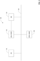
- FIG. 3 a block diagram illustrates a computing system 300 that can serve as the target computer system 150 according to one embodiment. While FIG. 3 illustrates various components of a computer system, it is not intended to represent any particular architecture or manner of interconnecting the components as such details are not germane to the present disclosure.
- Network computers and other data processing systems for example, handheld computers, personal digital assistants (PDAs), cellular telephones, entertainment systems, consumer electronic devices, etc.
- PDAs personal digital assistants
- cellular telephones for example, handheld computers, personal digital assistants (PDAs), cellular telephones, entertainment systems, consumer electronic devices, etc.
- consumer electronic devices etc.
- Computing system 300 includes a CPU 310, a GPU 330.
- CPU 310 and GPU 330 are included on separate integrated circuits (ICs) or packages. In other embodiments, however, CPU 310 and GPU 330, or the collective functionality thereof, may be included in a single IC or package.
- computing system 300 also includes a system memory 340 that may be accessed by CPU 310 and GPU 330.
- computing system 300 may comprise a supercomputer, a desktop computer, a laptop computer, a video-game console, an embedded device, a handheld device (e.g., a mobile telephone, smart phone, MP3 player, a camera, a GPS device, or other mobile device), or any other device that includes or is configured to include a GPU.
- a system memory 340 may be accessed by CPU 310 and GPU 330.
- computing system 300 may comprise a supercomputer, a desktop computer, a laptop computer, a video-game console, an embedded device, a handheld device (e.g., a mobile telephone, smart phone, MP3 player, a camera, a GPS device, or other mobile device), or any other device that includes or is configured to include a GPU.
- computing system 300 may also include conventional elements of a computing system, including a display device (e.g., cathode-ray tube, liquid crystal display, plasma display, etc.) for displaying content (e.g., graphics, video, etc.) of computing system 300, as well as input devices (e.g., keyboard, touch pad, mouse, etc.), storage devices (e.g., hard disc, optical disc, etc.) and communication devices (e.g., network interface). Any other elements may be included as desired. Although illustrated as coupled by a common communication link 350, multiple links 350 may be employed with the CPU 310 and GPU 330 connected to separate but interconnected links 350, as desired.
- a display device e.g., cathode-ray tube, liquid crystal display, plasma display, etc.
- content e.g., graphics, video, etc.
- input devices e.g., keyboard, touch pad, mouse, etc.
- storage devices e.g., hard disc, optical disc, etc.
- communication devices e.g.,
- GPU 330 assists CPU 310 by performing certain special functions, such as graphics-processing tasks and data-parallel, general-compute tasks, usually faster than CPU 310 could perform them in software.
- Link 350 may be any type of bus or communications fabric used in computer systems, including a peripheral component interface (PCI) bus, an accelerated graphics port (AGP) bus, a PCI Express (PCIE) bus, or another type of link, including non-bus links. If multiple links 350 are employed, they may be of different types.
- PCI peripheral component interface
- AGP accelerated graphics port
- PCIE PCI Express
- computing system 300 may include a local memory 320 that is coupled to GPU 330, as well as to link 350.
- Local memory 320 is available to GPU 330 to provide access to certain data (such as data that is frequently used) faster than would be possible if the data were stored in system memory 340.
- Both CPU 310 and GPU 330 can also contain caches or local memory within them.
- embodiments may employ any number of CPUs 310 and GPUs 330 as desired. Where multiple CPUs 310 or GPUs 330 are employed, each of the CPUs 310 and GPUs 330 may be of different types and architectures. Portions of the application 120 may be executed on different GPUs 330 as desired.
- the computer system 300 may employ one or more specialized co-processor devices (not illustrated in FIG. 3 ), such as cryptographic co-processors, which may be coupled to one or more of the CPUs 310 and GPUs 330, using the link 350 or other links as desired.
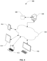
- FIG. 4 a block diagram illustrates a network of interconnected programmable devices 400, including server 430 and an associated datastore 440, as well as a desktop computer 410, a laptop 412, a tablet 414, and a mobile phone 416. Any of these programmable devices may be the developer system 100 or the target system 105 of FIG. 1 .
- the network 420 that interconnects the programmable devices may be any type of network, wired or wireless, local or wide area, public or private, using any desired network communication protocols for transport of data from one system to the other. Although illustrated as a single network 420, any number of interconnected networks may be used to connect the various programmable devices, which may employ different network technology.
- the desktop workstation 410 may be the developer system 100 of FIG. 1 , distributing the application 120 to the server 430, which in turn may distribute the application 120 to multiple devices 412, 414, and 416, each of which may employ a different GPU as well as other different components.
- a unified programming interface may be used to develop software on a system generally corresponding to that described above with respect to Fig. 2 for execution on a system generally corresponding to that described above with respect to Fig. 3 .
- An example of such a unified programming interface is disclosed in co-pending Provisional U.S. Patent Application 62/005,821, filed May 30, 2014 and entitled "System and Method for Unified Application Programming Interface and Model".
- a first level is things that must be defined at the time a rendering pass is started and cannot be changed until the rendering pass is complete.
- First and foremost of these is the image that is being rendered to, i.e., the frame buffer configuration.
- Frame buffer configuration can include buffer size and dimensions, color parameters, etc.
- the fixation of frame buffer configuration at the start and for the duration of a render pass is in contradistinction to prior art GPU frameworks/APIs, in which change to frame buffer configuration is treated just like any other command, and can thus appear at any point, including in the middle of a rendering pass. Further aspects of frame buffer configuration are described in the co-pending application mentioned above.
- a second level for is choosing a pipeline state object, which includes all of the graphics state that must be compiled into GPU code. Because running the GPU compiler on the target system is computationally expensive, it is preferable to do all of this at once, generally not at run time, but rather at the time the application is installed on the target system or when the application is loaded for execution. Further aspects and details of the pipeline state object are discussed in greater detail below.
- APIs may be developed that make a developer aware of when the code being written will result in a computationally expensive and time-consuming recompile. Further aspects of the pipeline state object are described below.
- a third level is state options that are easy/inexpensive to change on the fly (e.g., during execution of the application) without the necessity of compiling new GPU code. Further aspects of these state options are described below as well as in the co-pending application.
- a command or sequence of commands to render an object to the frame buffer can be created.
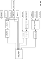
- this task can fall to a render command encoder 544 as illustrated in Fig. 5B .
- Render command encoder 544 uses as inputs texture object 510, buffer object 504, sampler object 508, depth stencil state object 538, and pipeline state object 542 to create a render command which may be rendered at a destination.
- a frame buffer descriptor can be configured as part of beginning a render command.
- the application can append a sequence of SetPipelineState, SetlnexpensiveState, and Draw commands to declare the set of objects that will be drawn into the frame buffer. Put another way: for each FramebufferDescriptor and/or RenderCommand, there can be one or more of the input objects and draw commands issued, and then the RenderCommand can be ended by the application to tell the graphics system that no more commands will be appended.
- Sampler 508 may be an immutable objected constructed using the Device method newSamplerWithDescriptor, which uses the sampler descriptor object 520 as an input value.
- Sampler descriptor object 520 may in turn be a mutable container for sampler properties including filtering options, addressing modes, maximum anisotropy, level-of-detail parameters, and depth comparison mode.
- desired values for sampler properties may be set in the sampler descriptor object 520 before it is used as an input in constructing the sampler 508.
- Depth stencil state object 538 may be a mutable object used in constructing the render command encoder object 544.
- Depth stencil state object 538 may itself be constructed using depth stencil state descriptor object 530, which may be a mutable state object that contains settings for depth and/or stencil state.
- depth stencil state descriptor object 530 may include a depth value for setting the depth, stencil back face state and stencil front face state properties for specifying separate stencil states for front and back-facing primitives, and a depth compare function property for specifying how a depth test is performed. For example, leaving the value of the depth compare function property at its default value indicates that the depth test always passes, which means an incoming fragment remains a candidate to replace the data at the specified location.
- a fragment's depth value fails the depth test, the incoming fragment is discarded.
- Construction of a custom depth stencil state descriptor object 530 itself may require creation of a stencil state object 522 which may be an immutable state object.
- Other graphics states may also be part of the pipeline.
- Pipeline state 542 may be an object containing compiled graphics rendering state, such as rasterization (including multisampling), visibility, and blend state.
- Pipeline state 542 may also contain programmable states such as two graphics shader functions to be executed on the GPU. One of these shader functions may be for vertex operations and one for fragment operations.
- the state in the pipeline state object 542 may generally be assembled and compiled at runtime.
- Pipeline state object 542 may be constructed using the pipeline state descriptor object 540 which may be a mutable descriptor object and a container for graphics rendering states.
- a pipeline state descriptor object 540 may be constructed and then its values may be set as desired.
- a rasterization enabled property BOOL type
- NO a rasterization enabled property
- Disabling rasterization may be useful to obtain feedback from vertex-only transformations.
- Other possible values that may be set include vertex and fragment function properties that help specify the vertex and fragment shaders, and a value for the blend state that specifies the blend state of a specified frame buffer attachment.
- the frame buffer attachment supports multisampling, then multiple samples can be created per fragment, and the following pipeline state properties can be set to determine coverage: the sampleCount property for the number of samples for each fragment, the sampleMask property for specifying a bitmask that is initially bitwise ANDed with the coveragemask produced by the rasterizer (by default, the sampleMask bitmask may generally be all ones, so a bitwise AND with that bitmask does not change any values; an alphaToCoverageEnabled property to specify if the alpha channel fragment output may be used as a coverage mask, an alphaToOneEnabled property for setting the alpha channel fragment values, and a sampleCoverage property specifying a value (between 0.0 and 1.0, inclusive) that is used to generate a coverage mask, which may then be bitwise ANDed with the coverage value produced by the rasterizer.
- the sampleCount property for the number of samples for each fragment
- the sampleMask property for specifying a bitmask that is initially bitwise
- Pipeline state descriptor object 540 itself may be constructed using one or objects that include function object 524, blend state 526, and pixel format 528.
- Function object 524 may represent a handle to a single function that runs on the GPU and may be created by compiling source code from an input value string. Function object 524 generally only relates to state values on graphics apps but not compute apps.
- Blend state 526 may be a mutable object containing values for blending. Blending may be a fragment operation that uses a highly configurable blend function to mix the incoming fragment's color data (source) with values in the frame buffer (destination). Blend functions may determine how the source and destination fragment values are combined with blend factors.
- Some of the properties that define the blend state may include 1) blending enabled property (BOOL value) for enabling blending; 2) writeMask property for specifying a bitmask that restricts which color bits are blended; 3) rgbBlendFunciton and alphaBlendFunction properties for assigning blend functions for the RGB and Alpha fragment data; and 4) sourceRGBBIendFactor, sourceAlphaBlendFactor, destinationRGBBIendFactor, and destinationAlphaBlendFactor properties for assigning source and destination blend factors.
- BOOL value blending enabled property
- writeMask property for specifying a bitmask that restricts which color bits are blended
- rgbBlendFunciton and alphaBlendFunction properties for assigning blend functions for the RGB and Alpha fragment data
- sourceRGBBIendFactor, sourceAlphaBlendFactor, destinationRGBBIendFactor, and destinationAlphaBlendFactor properties for assigning source and destination blend
- pipeline objects can be created at any time, although it may be desirable to create them early during application launch. This allows selection of a pre-created pipeline during the second level of execution described above.
- render command encoder object 544 may be constructed using those objects.
- first one or more frame buffer attachments 532 each of which containing the state of a destination for rendering commands e.g., color buffer, depth buffer, or stencil buffer
- a mutable frame buffer descriptor object 534 that contains the frame buffer state, including its associated attachments may be constructed.
- render command encoder object 544 can be constructed by calling a command buffer method (e.g., renderCommandEncoderWithFramebuffer).
- a pipeline state object 542 to represent the compiled pipeline state such as shader, rasterization (including multisampling), visibility, and blend state may be constructed by first creating the mutable descriptor object, pipeline state descriptor 540, and setting the desired graphics rendering state for the render-to-texture operation for pipeline state descriptor object 540.
- a render command encoder method e.g., setPipelineState
- setPipelineState may be called to associate the pipeline state object 542 to the render command encoder 544.
- pipelines can be really expensive to create because they invoke the compiler.
- an application would create many pipelines upon launch or when loading content, and then for each frame create a render command encoder and, in sequence, set the pipelines, other states, and resources necessary for each object to draw.
- a render command can have one "current" pipeline, which can be changed over time.
- An application can also create a pipeline at any time, including just before execution, but it may take an unsatisfyingly long time if done during animation.
- a pipeline can be used with many different render commands. (For example, an application could create one pipeline and hold onto it forever, where a new render command can be created for each frame, and for each frame the pipeline can be used to draw an object.
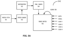
- a pipeline state object 542 is illustrated in Fig. 5A .
- a pipeline state object can be associated, for example, with an object to be drawn.
- the illustrated pipeline state object 542 includes five components, a vertex fetch 501, a vertex shader 502, a rasterization 503, a fragment shader 504, and a frame buffer 506.
- each of these objects would have been controlled by a separate API.
- the data flow from the vertex shader to the fragment shader is an interaction that is tied very closely to the code generation for execution on the GPU.
- illustrated blend operation 508 reads data from the frame buffer, modifies it in some way, and writes it back to the frame buffer. This operation, too, is closely linked to the GPU code generation and compilation.
- pipeline state objects are immutable objects that represent compiled machine code.
- pipeline state objects By use of different pipeline state objects for various graphical operations, when a draw call is made for an object associated with a particular pipeline state object, it is not necessary to look at the state of the API to determine, for example, whether a shader must be compiled because all states associated with the application program have already had corresponding GPU code generated, compiled, and stored so as to be ready for execution with whatever parameters are supplied on the fly during application run time.
- pipeline state objects can encapsulate everything that requires code generation. What requires code generation/compilation is different from GPU to GPU, so it is desirable to create a union of all such functions so that general API can be used with a variety of GPU hardware.
- Exemplary pipeline state objects can encapsulate the following: vertex fetch configuration, vertex shader, fragment shader, blend state, color formats attached to frame buffer, multi-sample mask, depth write enabled state, and rasterization enabled state.
- Program instructions and/or a database that represent and embody the described techniques and mechanisms may be stored on a machine-readable storage medium.
- the program instructions may include machine-readable instructions that when executed by the machine, cause the machine to perform the actions of the techniques described herein.
- a machine-readable storage medium may include any storage media accessible by a computer during use to provide instructions and/or data to the computer, and may include multiple instances of a physical medium as if they were a single physical medium.
- a machine-readable storage medium may include storage media such as magnetic or optical media, e.g., disk (fixed or removable), tape, CD-ROM, DVD-ROM, CD-R, CD-RW, DVD-R, DVD-RW, or Blu-Ray.
- Storage media may further include volatile or non-volatile memory media such as RAM, ROM, non-volatile memory (e.g., flash memory) accessible via a peripheral interface such as the USB interface, etc.
- Storage media may include micro-electro-mechanical systems (MEMS), as well as storage media accessible via a communication medium such as a network and/or a wireless link.
- MEMS micro-electro-mechanical systems
Landscapes
- Engineering & Computer Science (AREA)
- Theoretical Computer Science (AREA)
- Physics & Mathematics (AREA)
- General Physics & Mathematics (AREA)
- General Engineering & Computer Science (AREA)
- Human Computer Interaction (AREA)
- Computer Graphics (AREA)
- Software Systems (AREA)
- Image Generation (AREA)
Description
- This disclosure relates generally to the field of computer programming. More particularly, but not by way of limitation, it relates to techniques for programming graphical and computational applications to execute on a variety of graphical and computational processors.
- Computers and other computational devices typically have at least one programmable processing element that is generally known as a central processing unit (CPU). They frequently also have other programmable processors that are used for specialized processing of various types, such as graphics processing operations, hence are typically called graphics processing units (GPUs). GPUs generally comprise multiple cores or processing elements designed for executing the same instruction on parallel data streams, making them more effective than general-purpose CPUs for algorithms in which processing of large blocks of data is done in parallel. In general, a CPU functions as the host and hands-off specialized parallel tasks to the GPUs.
- Several frameworks have been developed for heterogeneous computing platforms that have CPUs and GPUs. These frameworks include OpenGL™. OpenGL focuses on using the GPU for graphics processing and provides APIs for rendering 2D and 3D graphics.
- The OpenGL framework offers a C-like development environment in which users can create applications to run on various different types of CPUs, GPUs, digital signal processors (DSPs), and other processors. OpenGL also provides a compiler and a runtime environment in which code can be compiled and executed within a heterogeneous computing system. When using OpenGL, developers can use a single, unified language to target all of the processors for which an OpenGL driver is available. This is done by presenting the developer with an abstract platform model and application programming interface (API) that conceptualizes all of these architectures in a similar way, as well as an execution model supporting data and task parallelism across heterogeneous architectures.
- When an OpenGL program is executed, a series of API calls configure the system for execution, an embedded compiler compiles the OpenGL code, and the runtime asynchronously coordinates execution between parallel tasks. A typical OpenGL-based system runs source code through an embedded compiler on the end-user system to generate executable code for a target GPU available on that system. Then, the executable code, or portions of the executable code, are sent to the target GPU and are executed. However, this approach, particularly the compiling step, may take too long for some types of applications, such as graphics-intensive games.
- In some sense, OpenGL itself may be considered as a state machine, with each command potentially resulting in a state change that requires the generation and/or compilation of new GPU code. This arises from the fact that certain GPU functions rely on dedicated circuitry within the GPU, while others require use of the programmable features of the GPU. Depending on the particular GPU hardware being used, these types of state changes can be very expensive from a computation time perspective. Additionally, in recent years, evolution of GPU hardware has outpaced evolution of OpenGL, such that, in some sense, OpenGL APIs are mismatched to the hardware environment in which the programs will run. The result is that a developer may inadvertently be writing code that is particularly inefficient for at least some hardware on which it will run.
- Therefore, there is a need in the art for a framework for GPU programming that more closely relate the APIs to the underlying hardware, such that a developer is aware of the distinctions between the fixed-function portions and the programmable portions of modern GPUs. This awareness can enable a developer to write code that executes more efficiently on modern devices.
- Matt Sandy, "Direct X 12", 20 March 2014 (Retrieved from the Internet: http://blogs.msdn.com/b/directx/archive/2014/03/20/directx-12.aspx) describes the Direct3D 12 graphics API. The API contains a number of rendering pipeline features which aim to improve the efficiency of certain graphics algorithms through improved utilization of GPU hardware.
- Ivan Navraev, "Microsoft Introduction to Direct3D 12", 4 April 2014 (Retrieved from the Internet: https://www.slideshare.net/DevCentralAM D/introduction-to-dx12-by-ivan-nevraev) is a presentation previewing the Direct3D 12 API, and in particular, the pipeline state optimization performed by Direct3D 12.
-
WO 2012/082423 A1 discloses a system for access to accelerated processing device compute resources to user mode applications. The functionality disclosed allows user mode applications to provide commands to an accelerated processing device without the need for kernel mode transitions in order to access a unified ring buffer. Instead, applications are each provided with their own buffers, which the accelerated processing device hardware can access to process commands. With full operating system support, user mode applications are able to utilize the accelerated processing device in much the same way as a CPU. -
US 2011/063296 A1 discloses a method for storing processed data within buffer objects stored in buffer object memory from within shader engines executing on a GPU. The method comprises the steps of receiving a stream of one or more shading program commands via a graphics driver, executing, within a shader engine, at least one of the one or more shading program commands to generate processed data, determining from the stream of one or more shading program commands an address associated with a first data object stored within the buffer memory, and storing, from within the shader engine, the processed data in the first data object stored within the buffer memory. -
US 2008/001952 A1 discloses a system for binding resources to particular slots associated with shaders in a graphics pipeline. Resource dependencies between resources being utilized by each shader can be determined, and, based on these resource dependencies, common resource/slot associations can be computed. Each common resource/slot association identifies a particular one of the resources to be associated with a particular one of the slots. -
US 2013/265309 A1 discloses a process for rendering graphics that includes performing, with a hardware shading unit of a graphics processing unit (GPU) designated for vertex shading, vertex shading operations to shade input vertices so as to output vertex shaded vertices, wherein the hardware unit is configured to receive a single vertex as an input and generate a single vertex as an output. The process also includes performing, with the hardware shading unit of the GPU, a geometry shading operation to generate one or more new vertices based on one or more of the vertex shaded vertices, wherein the geometry shading operation operates on at least one of the one or more vertex shaded vertices to output the one or more new vertices. - The invention is defined by a method according to
claim 1, a system according to claim 8 and a non-transitory computer readable medium according to claim 14. - The dependent claims define further advantageous embodiments.
-
-
Figure 1 is a block diagram illustrating compilation, linking, and execution of a program according to one embodiment. -
Figure 2 is a block diagram illustrating a computer system for executing programs on a graphical processor unit according to one embodiment. -
Figure 3 is a block diagram illustrating a computer system for compiling and linking programs according to one embodiment. -
Figure 4 is a block diagram illustrating a networked system according to one embodiment. -
Figure 5A is a block diagram illustrating an exemplary pipeline state object according to one embodiment. -
Figure 5B is a block diagram illustrating operation of a render command encoder according to one embodiment. - An innovative GPU framework and related APIs present more accurate representations of the target hardware so that the distinctions between the fixed-function and programmable features of the GPU are perceived by a developer. This permits a program and/or a graphics object generated or manipulated by the program to be understood as not just code, but machine states that are associated with the code. When such an object is defined, the definitional components requiring programmable GPU features can be compiled only once and reused repeatedly as needed. Similarly, when a state change is made, the state changes correspond to the state changes made on the hardware. Additionally, the creation of these immutable objects prevents a developer from inadvertently changing portions of the program or object that cause it to behave differently than intended.
- As used herein, the term "a computer system" can refer to a single computer or a plurality of computers working together to perform the function described as being performed on or by a computer system. Similarly, a machine-readable medium can refer to a single physical medium or a plurality of media that may together contain the indicated information stored thereon. A processor can refer to a single processing element or a plurality of processing elements, implemented either on a single chip or on multiple processing chips.
- It will be appreciated that in the development of any actual implementation (as in any development project), numerous decisions must be made to achieve the developers' specific goals (e.g., compliance with system- and business-related constraints), and that these goals may vary from one implementation to another. It will also be appreciated that such development efforts might be complex and time-consuming, but would nevertheless be a routine undertaking for those of ordinary skill in the design an implementation of systems having the benefit of this disclosure.
- Turning now to
FIG. 1 , adeveloper computer system 100 and atarget computer system 105 are illustrated in block diagram form according to one embodiment. A developer can create and submit source code in the unifiedprogramming interface 110, which can be a GPU-specific programming language. Theunified programming interface 110 may provide a single framework for developers to write their GPU programing code on. Once the code is written, it may be directed to acompiler 115, which can be a compiler for a GPU-specific programming language, and which may parse the source code and generate a machine-independent programming language-independent representation. The result may then be distributed from thedeveloper computer system 100 toapplication 120.Application 120 can contain the shader code in a device-independent form (in addition to everything else the application contains: CPU code, text, other resources, etc.). - The
application 120 may be delivered to thetarget machine 105 in any desired manner, including electronic transport over a network and physical transport of machine-readable media. This generally involves delivery of theapplication 120 to a server (not shown inFIG. 1 ) from which thetarget system 105 may obtain theapplication 120. Theapplication 120 may be bundled with other data, such as run-time libraries, installers, etc. that may be useful for the installation of theapplication 120 on thetarget system 105. In some situations, theapplication 120 may be provided as part of a larger package of software. - Upon launch of the
application 120, one action performed by the application can be creation of a collection ofpipeline objects 155 that may includestate information 125,fragment shaders 130, andvertex shaders 135, the application may be compiled by an embeddedGPU compiler 145 that compiles the representation provided by thecompiler 115 into native binary code for theGPU 150. The compiled native code may be cached incache 140 or stored elsewhere in thetarget system 105 to improve performance if the same pipeline is recreated later, such as during future launches of the application. Finally, theGPU 150 may execute the native binary code, performing the graphics and compute kernels for data parallel operations. - Referring now to
FIG. 2 , a block diagram illustrates acomputer system 200 that can serve as thedeveloper system 100 according to one embodiment. WhileFIG. 2 illustrates various components of a computer system, it is not intended to represent any particular architecture or manner of interconnecting the components as such details are not germane to the present disclosure. Network computers and other data processing systems (for example, handheld computers, personal digital assistants (PDAs), cellular telephones, entertainment systems, consumer electronic devices, etc.) which have fewer components or perhaps more components may also be used to implement one or more embodiments. - As illustrated in
FIG. 2 , thecomputer system 200, which is a form of a data processing system, includes abus 222 which is coupled to a microprocessor(s) 216, which may be CPUs and/or GPUs, amemory 212, which may include one or both of a volatile read/write random access memory (RAM) and a read-only memory (ROM), and anon-volatile storage device 214. The microprocessor(s) 216 may retrieve instructions from thememory 212 and thestorage device 214 and execute theinstructions using cache 218 to perform operations described above. Thelink 222 interconnects these various components together and also interconnects thesecomponents display controller 206 anddisplay device 220 and to peripheral devices such as input/output (I/O)devices 204 which may be mice, keyboards, touch screens, modems, network interfaces, printers and other devices which are well known in the art. Typically, the input/output devices 204 are coupled to the system through input/output controllers 202. Where volatile RAM is included inmemory 212, the RAM is typically implemented as dynamic RAM (DRAM), which requires power continually in order to refresh or maintain the data in the memory. Thedisplay controller 206 anddisplay device 220 may optionally include one or more GPUs to process display data. - The
storage device 214 is typically a magnetic hard drive, an optical drive, a non-volatile solid-state memory device, or other types of memory systems, which maintain data (e.g. large amounts of data) even after power is removed from the system. WhileFIG. 2 shows that thestorage device 214 is a local device coupled directly to the rest of the components in the data processing system, embodiments may utilize a non-volatile memory which is remote from the system, such as a network storage device which is coupled to the data processing system through anetwork interface 210, which may be a wired or wireless networking interface. Thelink 222 may include one or more links connected to each other through various bridges, controllers, and/or adapters as is well known in the art. Although only a single element of each type is illustrated inFIG. 2 for clarity, multiple elements of any or all of the various element types may be used as desired. - Referring now to
FIG. 3 , a block diagram illustrates a computing system 300 that can serve as thetarget computer system 150 according to one embodiment. WhileFIG. 3 illustrates various components of a computer system, it is not intended to represent any particular architecture or manner of interconnecting the components as such details are not germane to the present disclosure. Network computers and other data processing systems (for example, handheld computers, personal digital assistants (PDAs), cellular telephones, entertainment systems, consumer electronic devices, etc.) which have fewer components or perhaps more components may also be used to implement one or more embodiments. - Computing system 300 includes a CPU 310, a
GPU 330. In the embodiment illustrated inFIG. 3 , CPU 310 andGPU 330 are included on separate integrated circuits (ICs) or packages. In other embodiments, however, CPU 310 andGPU 330, or the collective functionality thereof, may be included in a single IC or package. - In addition, computing system 300 also includes a
system memory 340 that may be accessed by CPU 310 andGPU 330. In various embodiments, computing system 300 may comprise a supercomputer, a desktop computer, a laptop computer, a video-game console, an embedded device, a handheld device (e.g., a mobile telephone, smart phone, MP3 player, a camera, a GPS device, or other mobile device), or any other device that includes or is configured to include a GPU. Although not illustrated inFIG. 3 , computing system 300 may also include conventional elements of a computing system, including a display device (e.g., cathode-ray tube, liquid crystal display, plasma display, etc.) for displaying content (e.g., graphics, video, etc.) of computing system 300, as well as input devices (e.g., keyboard, touch pad, mouse, etc.), storage devices (e.g., hard disc, optical disc, etc.) and communication devices (e.g., network interface). Any other elements may be included as desired. Although illustrated as coupled by a common communication link 350, multiple links 350 may be employed with the CPU 310 andGPU 330 connected to separate but interconnected links 350, as desired. -
GPU 330 assists CPU 310 by performing certain special functions, such as graphics-processing tasks and data-parallel, general-compute tasks, usually faster than CPU 310 could perform them in software. -
GPU 330 is coupled with CPU 310 andsystem memory 340 over link 350. Link 350 may be any type of bus or communications fabric used in computer systems, including a peripheral component interface (PCI) bus, an accelerated graphics port (AGP) bus, a PCI Express (PCIE) bus, or another type of link, including non-bus links. If multiple links 350 are employed, they may be of different types. - In addition to
system memory 340, computing system 300 may include a local memory 320 that is coupled toGPU 330, as well as to link 350. Local memory 320 is available toGPU 330 to provide access to certain data (such as data that is frequently used) faster than would be possible if the data were stored insystem memory 340. Both CPU 310 andGPU 330 can also contain caches or local memory within them. - Although a single CPU 310 and
GPU 330 are illustrated inFIG. 3 , embodiments may employ any number of CPUs 310 andGPUs 330 as desired. Where multiple CPUs 310 orGPUs 330 are employed, each of the CPUs 310 andGPUs 330 may be of different types and architectures. Portions of theapplication 120 may be executed ondifferent GPUs 330 as desired. In addition, the computer system 300 may employ one or more specialized co-processor devices (not illustrated inFIG. 3 ), such as cryptographic co-processors, which may be coupled to one or more of the CPUs 310 andGPUs 330, using the link 350 or other links as desired. - Turning now to
FIG. 4 , a block diagram illustrates a network of interconnectedprogrammable devices 400, including server 430 and an associateddatastore 440, as well as adesktop computer 410, a laptop 412, a tablet 414, and amobile phone 416. Any of these programmable devices may be thedeveloper system 100 or thetarget system 105 ofFIG. 1 . The network 420 that interconnects the programmable devices may be any type of network, wired or wireless, local or wide area, public or private, using any desired network communication protocols for transport of data from one system to the other. Although illustrated as a single network 420, any number of interconnected networks may be used to connect the various programmable devices, which may employ different network technology. In one example, thedesktop workstation 410 may be thedeveloper system 100 ofFIG. 1 , distributing theapplication 120 to the server 430, which in turn may distribute theapplication 120 tomultiple devices 412, 414, and 416, each of which may employ a different GPU as well as other different components. - A unified programming interface may be used to develop software on a system generally corresponding to that described above with respect to
Fig. 2 for execution on a system generally corresponding to that described above with respect toFig. 3 . An example of such a unified programming interface is disclosed in co-pending ProvisionalU.S. Patent Application 62/005,821, filed May 30, 2014 - Aspects of an innovative GPU programming framework and associated APIs may be best understood as a tiered-structure having three levels:
- A first level is things that must be defined at the time a rendering pass is started and cannot be changed until the rendering pass is complete. First and foremost of these is the image that is being rendered to, i.e., the frame buffer configuration. Frame buffer configuration can include buffer size and dimensions, color parameters, etc. The fixation of frame buffer configuration at the start and for the duration of a render pass is in contradistinction to prior art GPU frameworks/APIs, in which change to frame buffer configuration is treated just like any other command, and can thus appear at any point, including in the middle of a rendering pass. Further aspects of frame buffer configuration are described in the co-pending application mentioned above.
- A second level for is choosing a pipeline state object, which includes all of the graphics state that must be compiled into GPU code. Because running the GPU compiler on the target system is computationally expensive, it is preferable to do all of this at once, generally not at run time, but rather at the time the application is installed on the target system or when the application is loaded for execution. Further aspects and details of the pipeline state object are discussed in greater detail below. By incorporating functionality triggering a GPU code re-compile into a pipeline state object, APIs may be developed that make a developer aware of when the code being written will result in a computationally expensive and time-consuming recompile. Further aspects of the pipeline state object are described below.
- A third level is state options that are easy/inexpensive to change on the fly (e.g., during execution of the application) without the necessity of compiling new GPU code. Further aspects of these state options are described below as well as in the co-pending application.
- Once a frame buffer has been defined, a command or sequence of commands to render an object to the frame buffer can be created. In some embodiments, this task can fall to a render
command encoder 544 as illustrated inFig. 5B . Rendercommand encoder 544 uses asinputs texture object 510,buffer object 504,sampler object 508, depthstencil state object 538, andpipeline state object 542 to create a render command which may be rendered at a destination. A frame buffer descriptor can be configured as part of beginning a render command. Then, the application can append a sequence of SetPipelineState, SetlnexpensiveState, and Draw commands to declare the set of objects that will be drawn into the frame buffer. Put another way: for each FramebufferDescriptor and/or RenderCommand, there can be one or more of the input objects and draw commands issued, and then the RenderCommand can be ended by the application to tell the graphics system that no more commands will be appended. -
Sampler 508 may be an immutable objected constructed using the Device method newSamplerWithDescriptor, which uses the sampler descriptor object 520 as an input value. Sampler descriptor object 520 may in turn be a mutable container for sampler properties including filtering options, addressing modes, maximum anisotropy, level-of-detail parameters, and depth comparison mode. To construct thesampler 508, desired values for sampler properties may be set in the sampler descriptor object 520 before it is used as an input in constructing thesampler 508. - Depth
stencil state object 538 may be a mutable object used in constructing the rendercommand encoder object 544. Depthstencil state object 538 may itself be constructed using depth stencilstate descriptor object 530, which may be a mutable state object that contains settings for depth and/or stencil state. For example, depth stencilstate descriptor object 530 may include a depth value for setting the depth, stencil back face state and stencil front face state properties for specifying separate stencil states for front and back-facing primitives, and a depth compare function property for specifying how a depth test is performed. For example, leaving the value of the depth compare function property at its default value indicates that the depth test always passes, which means an incoming fragment remains a candidate to replace the data at the specified location. If a fragment's depth value fails the depth test, the incoming fragment is discarded. Construction of a custom depth stencilstate descriptor object 530 itself may require creation of astencil state object 522 which may be an immutable state object. Other graphics states may also be part of the pipeline. -
Pipeline state 542, examples of which are discussed below, may be an object containing compiled graphics rendering state, such as rasterization (including multisampling), visibility, and blend state.Pipeline state 542 may also contain programmable states such as two graphics shader functions to be executed on the GPU. One of these shader functions may be for vertex operations and one for fragment operations. The state in thepipeline state object 542 may generally be assembled and compiled at runtime.Pipeline state object 542 may be constructed using the pipelinestate descriptor object 540 which may be a mutable descriptor object and a container for graphics rendering states. - In general to construct the
Pipeline state object 542, first a pipelinestate descriptor object 540 may be constructed and then its values may be set as desired. For example, a rasterization enabled property (BOOL type) may be set to NO, so that all primitives are dropped before rasterization, and no fragments are processed. Disabling rasterization may be useful to obtain feedback from vertex-only transformations. Other possible values that may be set include vertex and fragment function properties that help specify the vertex and fragment shaders, and a value for the blend state that specifies the blend state of a specified frame buffer attachment. If the frame buffer attachment supports multisampling, then multiple samples can be created per fragment, and the following pipeline state properties can be set to determine coverage: the sampleCount property for the number of samples for each fragment, the sampleMask property for specifying a bitmask that is initially bitwise ANDed with the coveragemask produced by the rasterizer (by default, the sampleMask bitmask may generally be all ones, so a bitwise AND with that bitmask does not change any values; an alphaToCoverageEnabled property to specify if the alpha channel fragment output may be used as a coverage mask, an alphaToOneEnabled property for setting the alpha channel fragment values, and a sampleCoverage property specifying a value (between 0.0 and 1.0, inclusive) that is used to generate a coverage mask, which may then be bitwise ANDed with the coverage value produced by the rasterizer. - Pipeline
state descriptor object 540 itself may be constructed using one or objects that includefunction object 524,blend state 526, andpixel format 528.Function object 524 may represent a handle to a single function that runs on the GPU and may be created by compiling source code from an input value string.Function object 524 generally only relates to state values on graphics apps but not compute apps.Blend state 526 may be a mutable object containing values for blending. Blending may be a fragment operation that uses a highly configurable blend function to mix the incoming fragment's color data (source) with values in the frame buffer (destination). Blend functions may determine how the source and destination fragment values are combined with blend factors. Some of the properties that define the blend state may include 1) blending enabled property (BOOL value) for enabling blending; 2) writeMask property for specifying a bitmask that restricts which color bits are blended; 3) rgbBlendFunciton and alphaBlendFunction properties for assigning blend functions for the RGB and Alpha fragment data; and 4) sourceRGBBIendFactor, sourceAlphaBlendFactor, destinationRGBBIendFactor, and destinationAlphaBlendFactor properties for assigning source and destination blend factors. - In general, it may be desirable to know the pixel formats of every render target (multiple colors, depth, and stencil) as part of building the RenderPipelineState. This can allow the compiler to know how to format the output memory. Additionally, pipeline objects can be created at any time, although it may be desirable to create them early during application launch. This allows selection of a pre-created pipeline during the second level of execution described above.
- Once all the required objects have been constructed, render
command encoder object 544 may be constructed using those objects. Thus, in summary, to construct and initialize the rendercommand encoder object 544, in one embodiment, first one or moreframe buffer attachments 532 each of which containing the state of a destination for rendering commands (e.g., color buffer, depth buffer, or stencil buffer) may be constructed. Next, a mutable framebuffer descriptor object 534 that contains the frame buffer state, including its associated attachments may be constructed. Then using the framebuffer descriptor object 534, rendercommand encoder object 544 can be constructed by calling a command buffer method (e.g., renderCommandEncoderWithFramebuffer). - At this point, a
pipeline state object 542 to represent the compiled pipeline state, such as shader, rasterization (including multisampling), visibility, and blend state may be constructed by first creating the mutable descriptor object,pipeline state descriptor 540, and setting the desired graphics rendering state for the render-to-texture operation for pipelinestate descriptor object 540. Afterpipeline state object 542 has been created, a render command encoder method (e.g., setPipelineState) may be called to associate thepipeline state object 542 to the rendercommand encoder 544. - To reiterate, pipelines can be really expensive to create because they invoke the compiler. Ideally an application would create many pipelines upon launch or when loading content, and then for each frame create a render command encoder and, in sequence, set the pipelines, other states, and resources necessary for each object to draw. At any given time, a render command can have one "current" pipeline, which can be changed over time. The act of switching to an already-created pipeline can be expected to be inexpensive. An application can also create a pipeline at any time, including just before execution, but it may take an unsatisfyingly long time if done during animation. Thus, once created, a pipeline can be used with many different render commands. (For example, an application could create one pipeline and hold onto it forever, where a new render command can be created for each frame, and for each frame the pipeline can be used to draw an object.
- An exemplary
pipeline state object 542 is illustrated inFig. 5A . A pipeline state object can be associated, for example, with an object to be drawn. The illustratedpipeline state object 542 includes five components, a vertex fetch 501, avertex shader 502, arasterization 503, afragment shader 504, and aframe buffer 506. Historically, each of these objects would have been controlled by a separate API. However, in any given instantiation associated with a real-world implementation, there is a predefined data flow among these objects. For example, the data flow from the vertex shader to the fragment shader is an interaction that is tied very closely to the code generation for execution on the GPU. Similarly, illustratedblend operation 508 reads data from the frame buffer, modifies it in some way, and writes it back to the frame buffer. This operation, too, is closely linked to the GPU code generation and compilation. - Because of the fixed relationships between the objects and the linkage between these relationships and the GPU code generation and compilation process, it is advantageous to combine them into a single pipeline state object. This allows the requisite GPU code to be generated and compiled only one time, either when the application is installed on the target system or when the application is loaded. The GPU machine code so-generated is then stored, allowing the code to be retrieved, passed to the GPU, and executed whenever a particular object is drawn. This avoids the necessity of generating and compiling the associated code on the fly each time a particular object is to be drawn.
- In other words, pipeline state objects are immutable objects that represent compiled machine code. By use of different pipeline state objects for various graphical operations, when a draw call is made for an object associated with a particular pipeline state object, it is not necessary to look at the state of the API to determine, for example, whether a shader must be compiled because all states associated with the application program have already had corresponding GPU code generated, compiled, and stored so as to be ready for execution with whatever parameters are supplied on the fly during application run time.
- In the prior art, determinations whether a code recompilation was necessary were typically made by generating a hash function for each compiled and cached GPU code segment. When a state was changed that might require new code generation, a corresponding hash of the state could be generated and checked against the available cached compiled states to determine whether the required executable code was already available. While this saved some time for instances in which the requisite code had already been compiled, even the checking process could be unduly time consuming in some applications. Thus, the use of pipeline state objects as described above can save significant time during program execution because the generation and compilation of all required GPU code can be front loaded to application installation or initiation, rather than taking place during the rendering operations.
- While the parameters that affect code generation are incorporated into the immutable pipeline state object, there are still a variety of other parameters that do not affect code generation or require recompilation of the GPU code. These data and parameters, e.g., size of viewport, input textures, input vertex data, occlusion queries, etc., are available to be modified through API calls. In short, this can be understood as follows: changing the data that is manipulated is easy and computationally inexpensive, and is thus encapsulated in mutable objects and modifiable by API calls. Changing the way the data is manipulated is harder and computationally intensive, and is thus encapsulated in immutable objects that are constructed and compiled once and not at draw time. Thus, the goal for pipeline state objects is to encapsulate everything that requires code generation. What requires code generation/compilation is different from GPU to GPU, so it is desirable to create a union of all such functions so that general API can be used with a variety of GPU hardware. Exemplary pipeline state objects can encapsulate the following: vertex fetch configuration, vertex shader, fragment shader, blend state, color formats attached to frame buffer, multi-sample mask, depth write enabled state, and rasterization enabled state.
- Program instructions and/or a database that represent and embody the described techniques and mechanisms may be stored on a machine-readable storage medium. The program instructions may include machine-readable instructions that when executed by the machine, cause the machine to perform the actions of the techniques described herein.
- A machine-readable storage medium may include any storage media accessible by a computer during use to provide instructions and/or data to the computer, and may include multiple instances of a physical medium as if they were a single physical medium. For example, a machine-readable storage medium may include storage media such as magnetic or optical media, e.g., disk (fixed or removable), tape, CD-ROM, DVD-ROM, CD-R, CD-RW, DVD-R, DVD-RW, or Blu-Ray. Storage media may further include volatile or non-volatile memory media such as RAM, ROM, non-volatile memory (e.g., flash memory) accessible via a peripheral interface such as the USB interface, etc. Storage media may include micro-electro-mechanical systems (MEMS), as well as storage media accessible via a communication medium such as a network and/or a wireless link.
Claims (14)
- A method for creating a rendering pipeline for a rendering operation used by an application (120) executing on a target computer system (105) comprising a target Graphics Processing Unit GPU (150), the method comprising:prior to launch of the application (120) on the target computer system (105):generating GPU-specific code for operation on the GPU (150), wherein the GPU-specific code includes a vertex shader and a fragment shader; andcompiling the GPU-specific code to generate a compiled programmable state;during execution of the application (120) on the target computer system (105):assembling a mutable pipeline state descriptor object (540) adapted to set a desired graphic rendering state for the rendering operation, wherein the mutable pipeline state descriptor object (540) includes:a vertex state associated with the vertex shader;a fragment state associated with the fragment shader; anda rasterization state;compiling the vertex state, the fragment state, and the rasterization state to generate a compiled graphics rendering state;creating an immutable pipeline state object (542) containing the compiled programmable state and the compiled graphics rendering state, wherein the compiled programmable state encapsulates executable instructions for the GPU (150) and the compiled graphics rendering state externalizes mutable attributes requiring re-compilation when changed;constructing a render command encoder (544) for the rendering operation; andassociating the immutable pipeline state object (542) with the render command encoder (544).
- The method of claim 1, wherein the immutable pipeline state object (542) is compiled either when the application loads or when the application is installed, wherein the application is associated with the pipeline state object in that the application displays graphics that result from the pipeline state object.
- The method of claim 1 or claim 2, wherein the GPU-specific code is binary code.
- The method of any preceding claim, wherein the rendering operation is a render-to-texture operation.
- The method of any preceding claim, wherein the mutable pipeline state descriptor object (540) includes one or more of size of viewport, input textures, input vertex data, and occlusion queries.
- The method of any preceding claim, wherein the mutable pipeline state descriptor object (540) may be modified by API calls.
- The method of any preceding claim, wherein all parameters that effect code generation for the immutable pipeline state object are part of the compiled pipeline state.
- A system for creating a rendering pipeline for a rendering operation used by an application (120) executing on a target computer system (105) comprising a target Graphics Processing Unit, GPU (120), the system comprising:a CPU;a memory associated with the CPU for holding instructions for the CPU; wherein the CPU is adapted to, when executing the instructions, cause theproduction of graphics by:prior to launch of an application (120) on the target system (105):generating GPU-specific code for operation on the target GPU (150), wherein the GPU-specific code includes a vertex shader and a fragment shader; andcompiling the GPU-specific code to generate a compiled programmable state;during execution of the application (120) on the target system (105):assembling a mutable pipeline state descriptor object (540) adapted to set a desired graphic rendering state for the rendering operation, wherein the mutable pipeline state descriptor object (540) includes:a vertex state associated with the vertex shader;a fragment state associated with the fragment shader; anda rasterization state;compiling the vertex state, the fragment state, and the rasterization state to generate a compiled graphics rendering state;creating an immutable pipeline state object (542) containing the compiled programmable state and the compiled graphics rendering state, wherein the compiled programmable state encapsulates executable instructions for the GPU (150) and the compiled graphics rendering state externalizes mutable attributes requiring re-compilation when changed;constructing a render command encoder (544) for the rendering operation; andassociating the immutable pipeline state object (542) with the render command encoder (544).
- The system of claim 8 wherein the immutable pipeline state object (542) is compiled either when the application loads or when the application is installed, wherein the application is associated with the pipeline state object in that the application displays graphics that result from the pipeline state object.
- The system of claim 8 or claim 9, wherein the GPU-specific code is binary code.
- The system of any of claims 8 to 10, wherein the mutable pipeline state descriptor object (540) includes one or more of size of viewport, input textures, input vertex data, and occlusion queries.
- The system of any of claims 8 to 11, wherein the mutable pipeline state descriptor parameters may be modified by API calls.
- The system of any of claims 8 to 12, wherein the render command encoder further includes a mutable depth stencil state object and a mutable frame buffer descriptor object that are compiled during runtime.
- A non-transitory computer readable medium comprising instructions stored thereon, the instructions when executed causing one or more processors to execute one or more of the methods of claims 1 through 7.
Applications Claiming Priority (3)
| Application Number | Priority Date | Filing Date | Title |
|---|---|---|---|
| US201462005131P | 2014-05-30 | 2014-05-30 | |
| US14/501,933 US20150348224A1 (en) | 2014-05-30 | 2014-09-30 | Graphics Pipeline State Object And Model |
| PCT/US2015/032518 WO2015183855A1 (en) | 2014-05-30 | 2015-05-27 | Graphics pipeline state object and model |
Publications (2)
| Publication Number | Publication Date |
|---|---|
| EP3137985A1 EP3137985A1 (en) | 2017-03-08 |
| EP3137985B1 true EP3137985B1 (en) | 2022-01-26 |
Family
ID=53476973
Family Applications (1)
| Application Number | Title | Priority Date | Filing Date |
|---|---|---|---|
| EP15730892.5A Active EP3137985B1 (en) | 2014-05-30 | 2015-05-27 | Method and system to create a rendering pipeline |
Country Status (4)
| Country | Link |
|---|---|
| US (1) | US20150348224A1 (en) |
| EP (1) | EP3137985B1 (en) |
| CN (1) | CN106462375B (en) |
| WO (1) | WO2015183855A1 (en) |
Families Citing this family (14)
| Publication number | Priority date | Publication date | Assignee | Title |
|---|---|---|---|---|
| US20160316040A1 (en) * | 2015-04-27 | 2016-10-27 | Microsoft Technology Licensing, Llc | Providing pipeline for unified service and client interface |
| WO2017074377A1 (en) * | 2015-10-29 | 2017-05-04 | Intel Corporation | Boosting local memory performance in processor graphics |
| US9881352B2 (en) * | 2015-11-13 | 2018-01-30 | Intel Corporation | Facilitating efficient graphics commands processing for bundled states at computing devices |
| US10460513B2 (en) * | 2016-09-22 | 2019-10-29 | Advanced Micro Devices, Inc. | Combined world-space pipeline shader stages |
| US11055807B2 (en) * | 2017-06-12 | 2021-07-06 | Apple Inc. | Method and system for a transactional based display pipeline to interface with graphics processing units |
| US11080927B2 (en) * | 2017-11-30 | 2021-08-03 | Advanced Micro Devices, Inc. | Method and apparatus of cross shader compilation |
| CN109710229B (en) * | 2018-12-11 | 2022-03-15 | 中国航空工业集团公司西安航空计算技术研究所 | Architecture verification method and platform for graphics pipeline unit of GPU (graphics processing Unit) chip |
| CN111459584B (en) * | 2020-03-12 | 2024-04-12 | 支付宝(杭州)信息技术有限公司 | Page rendering method and device and electronic equipment |
| US12169703B2 (en) * | 2020-03-19 | 2024-12-17 | Advanced Micro Devices, Inc. | Graphics pipeline optimizations |
| US11868759B2 (en) | 2021-12-08 | 2024-01-09 | Advanced Micro Devices, Inc. | Shader source code performance prediction |
| CN115858078A (en) * | 2022-12-22 | 2023-03-28 | 北京字跳网络技术有限公司 | Special effect rendering method and device, material manufacturing system, equipment and storage medium |
| CN116206038A (en) * | 2023-03-13 | 2023-06-02 | 北京字跳网络技术有限公司 | Rendering method, rendering device, electronic equipment and storage medium |
| CN116841739B (en) * | 2023-06-30 | 2024-04-19 | 沐曦集成电路(杭州)有限公司 | Data packet reuse system for heterogeneous computing platforms |
| US20250036418A1 (en) * | 2023-07-26 | 2025-01-30 | Nvidia Corporation | Hardware and software support for parallel processing pipelines |
Citations (4)
| Publication number | Priority date | Publication date | Assignee | Title |
|---|---|---|---|---|
| US20080001952A1 (en) * | 2006-06-28 | 2008-01-03 | Microsoft Corporation | Fast reconfiguration of graphics pipeline state |
| US20110063296A1 (en) * | 2009-09-11 | 2011-03-17 | Bolz Jeffrey A | Global Stores and Atomic Operations |
| WO2012082423A1 (en) * | 2010-12-13 | 2012-06-21 | Advanced Micro Devices, Inc. | Graphics compute process scheduling |
| US20130265309A1 (en) * | 2012-04-04 | 2013-10-10 | Qualcomm Incorporated | Patched shading in graphics processing |
Family Cites Families (12)
| Publication number | Priority date | Publication date | Assignee | Title |
|---|---|---|---|---|
| US8274517B2 (en) * | 2003-11-14 | 2012-09-25 | Microsoft Corporation | Systems and methods for downloading algorithmic elements to a coprocessor and corresponding techniques |
| US7746347B1 (en) * | 2004-07-02 | 2010-06-29 | Nvidia Corporation | Methods and systems for processing a geometry shader program developed in a high-level shading language |
| US20060012604A1 (en) * | 2004-07-15 | 2006-01-19 | Avinash Seetharamaiah | Legacy processing for pixel shader hardware |
| US8698818B2 (en) * | 2008-05-15 | 2014-04-15 | Microsoft Corporation | Software rasterization optimization |
| US8286198B2 (en) * | 2008-06-06 | 2012-10-09 | Apple Inc. | Application programming interfaces for data parallel computing on multiple processors |
| US8610731B2 (en) * | 2009-04-30 | 2013-12-17 | Microsoft Corporation | Dynamic graphics pipeline and in-place rasterization |
| US8766988B2 (en) * | 2009-10-09 | 2014-07-01 | Nvidia Corporation | Providing pipeline state through constant buffers |
| US20130159630A1 (en) * | 2011-12-20 | 2013-06-20 | Ati Technologies Ulc | Selective cache for inter-operations in a processor-based environment |
| US9361079B2 (en) * | 2012-01-30 | 2016-06-07 | Nvidia Corporation | Method for compiling a parallel thread execution program for general execution |
| US20140354658A1 (en) * | 2013-05-31 | 2014-12-04 | Microsoft Corporation | Shader Function Linking Graph |
| US20150179142A1 (en) * | 2013-12-20 | 2015-06-25 | Nvidia Corporation | System, method, and computer program product for reduced-rate calculation of low-frequency pixel shader intermediate values |
| US9235871B2 (en) * | 2014-02-06 | 2016-01-12 | Oxide Interactive, LLC | Method and system of a command buffer between a CPU and GPU |
-
2014
- 2014-09-30 US US14/501,933 patent/US20150348224A1/en not_active Abandoned
-
2015
- 2015-05-27 WO PCT/US2015/032518 patent/WO2015183855A1/en not_active Ceased
- 2015-05-27 CN CN201580028651.4A patent/CN106462375B/en active Active
- 2015-05-27 EP EP15730892.5A patent/EP3137985B1/en active Active
Patent Citations (4)
| Publication number | Priority date | Publication date | Assignee | Title |
|---|---|---|---|---|
| US20080001952A1 (en) * | 2006-06-28 | 2008-01-03 | Microsoft Corporation | Fast reconfiguration of graphics pipeline state |
| US20110063296A1 (en) * | 2009-09-11 | 2011-03-17 | Bolz Jeffrey A | Global Stores and Atomic Operations |
| WO2012082423A1 (en) * | 2010-12-13 | 2012-06-21 | Advanced Micro Devices, Inc. | Graphics compute process scheduling |
| US20130265309A1 (en) * | 2012-04-04 | 2013-10-10 | Qualcomm Incorporated | Patched shading in graphics processing |
Non-Patent Citations (2)
| Title |
|---|
| IVAN NEVRAEV: "Microsoft Introduction to Direct3D 12", 4 April 2014 (2014-04-04), pages 1 - 43, XP055203398, Retrieved from the Internet <URL:http://www.google.de/url?sa=t&rct=j&q=&esrc=s&source=web&cd=2&cad=rja&uact=8&ved=0CDEQFjABahUKEwiCmsP_w-nGAhUKPhQKHcqZAP8&url=http%3A%2F%2Famd-dev.wpengine.netdna-cdn.com%2Fwordpress%2Fmedia%2F2012%2F10%2FIntroduction-To-DX12-Ivan-Nevraev.ppsx&ei=g9GsVcLMLor8UMqzgvgP&usg=AFQjCNH0huTmfeNNlI_Y7kH5XtvH> [retrieved on 20150720] * |
| MATT SANDY: "DirectX 12", INTERNET CITATION, 20 March 2014 (2014-03-20), pages 1 - 19, XP002742458, Retrieved from the Internet <URL:http://blogs.msdn.com/b/directx/archive/2014/03/20/directx-12.aspx> [retrieved on 20150720] * |
Also Published As
| Publication number | Publication date |
|---|---|
| US20150348224A1 (en) | 2015-12-03 |
| EP3137985A1 (en) | 2017-03-08 |
| CN106462375B (en) | 2019-06-07 |
| CN106462375A (en) | 2017-02-22 |
| WO2015183855A1 (en) | 2015-12-03 |
Similar Documents
| Publication | Publication Date | Title |
|---|---|---|
| US20150348224A1 (en) | Graphics Pipeline State Object And Model | |
| US10949944B2 (en) | System and method for unified application programming interface and model | |
| KR101732288B1 (en) | Sprite graphics rendering system | |
| US9477525B2 (en) | Application programming interfaces for data parallel computing on multiple processors | |
| US9799094B1 (en) | Per-instance preamble for graphics processing | |
| US9069567B1 (en) | High performance execution environment | |
| US20160217011A1 (en) | Application interface on multiple processors | |
| US11615575B2 (en) | Methods and systems for constructing a shader | |
| US9619918B2 (en) | Heterogenious 3D graphics processor and configuration method thereof | |
| US20150348280A1 (en) | Dynamic Generation Of Texture Atlases | |
| TW201712631A (en) | Data processing systems | |
| CN113838180B (en) | Rendering instruction processing method and related equipment thereof | |
| US20200234484A1 (en) | Graphics processing systems | |
| US8907979B2 (en) | Fast rendering of knockout groups using a depth buffer of a graphics processing unit | |
| US9183662B1 (en) | System and method for enabling scene program functionality | |
| US20210294579A1 (en) | Graphics pipeline optimizations | |
| GB2546308A (en) | Data processing systems | |
| US9218691B1 (en) | System and method for enabling scene program functionality | |
| CN120335878A (en) | Image processing method and related device and medium program | |
| AU2016213890B2 (en) | Data parallel computing on multiple processors | |
| Freeman et al. | Intel Graphics Media Accelerator Developer's Guide |
Legal Events
| Date | Code | Title | Description |
|---|---|---|---|
| STAA | Information on the status of an ep patent application or granted ep patent |
Free format text: STATUS: THE INTERNATIONAL PUBLICATION HAS BEEN MADE |
|
| PUAI | Public reference made under article 153(3) epc to a published international application that has entered the european phase |
Free format text: ORIGINAL CODE: 0009012 |
|
| STAA | Information on the status of an ep patent application or granted ep patent |
Free format text: STATUS: REQUEST FOR EXAMINATION WAS MADE |
|
| 17P | Request for examination filed |
Effective date: 20161130 |
|
| AK | Designated contracting states |
Kind code of ref document: A1 Designated state(s): AL AT BE BG CH CY CZ DE DK EE ES FI FR GB GR HR HU IE IS IT LI LT LU LV MC MK MT NL NO PL PT RO RS SE SI SK SM TR |
|
| AX | Request for extension of the european patent |
Extension state: BA ME |
|
| DAV | Request for validation of the european patent (deleted) | ||
| DAX | Request for extension of the european patent (deleted) | ||
| PUAG | Search results despatched under rule 164(2) epc together with communication from examining division |
Free format text: ORIGINAL CODE: 0009017 |
|
| STAA | Information on the status of an ep patent application or granted ep patent |
Free format text: STATUS: EXAMINATION IS IN PROGRESS |
|
| 17Q | First examination report despatched |
Effective date: 20180608 |
|
| B565 | Issuance of search results under rule 164(2) epc |
Effective date: 20180608 |
|
| RIC1 | Information provided on ipc code assigned before grant |
Ipc: G06F 3/14 20060101AFI20180605BHEP |
|
| RAP1 | Party data changed (applicant data changed or rights of an application transferred) |
Owner name: APPLE INC. |
|
| GRAP | Despatch of communication of intention to grant a patent |
Free format text: ORIGINAL CODE: EPIDOSNIGR1 |
|
| STAA | Information on the status of an ep patent application or granted ep patent |
Free format text: STATUS: GRANT OF PATENT IS INTENDED |
|
| INTG | Intention to grant announced |
Effective date: 20210415 |
|
| GRAJ | Information related to disapproval of communication of intention to grant by the applicant or resumption of examination proceedings by the epo deleted |
Free format text: ORIGINAL CODE: EPIDOSDIGR1 |
|
| STAA | Information on the status of an ep patent application or granted ep patent |
Free format text: STATUS: EXAMINATION IS IN PROGRESS |
|
| GRAP | Despatch of communication of intention to grant a patent |
Free format text: ORIGINAL CODE: EPIDOSNIGR1 |
|
| STAA | Information on the status of an ep patent application or granted ep patent |
Free format text: STATUS: GRANT OF PATENT IS INTENDED |
|
| INTC | Intention to grant announced (deleted) | ||
| INTG | Intention to grant announced |
Effective date: 20210915 |
|
| GRAS | Grant fee paid |
Free format text: ORIGINAL CODE: EPIDOSNIGR3 |
|
| GRAA | (expected) grant |
Free format text: ORIGINAL CODE: 0009210 |
|
| STAA | Information on the status of an ep patent application or granted ep patent |
Free format text: STATUS: THE PATENT HAS BEEN GRANTED |
|
| AK | Designated contracting states |
Kind code of ref document: B1 Designated state(s): AL AT BE BG CH CY CZ DE DK EE ES FI FR GB GR HR HU IE IS IT LI LT LU LV MC MK MT NL NO PL PT RO RS SE SI SK SM TR |
|
| REG | Reference to a national code |
Ref country code: GB Ref legal event code: FG4D |
|
| REG | Reference to a national code |
Ref country code: CH Ref legal event code: EP |
|
| REG | Reference to a national code |
Ref country code: AT Ref legal event code: REF Ref document number: 1465808 Country of ref document: AT Kind code of ref document: T Effective date: 20220215 |
|
| REG | Reference to a national code |
Ref country code: IE Ref legal event code: FG4D |
|
| REG | Reference to a national code |
Ref country code: DE Ref legal event code: R096 Ref document number: 602015076638 Country of ref document: DE |
|
| REG | Reference to a national code |
Ref country code: LT Ref legal event code: MG9D |
|
| REG | Reference to a national code |
Ref country code: NL Ref legal event code: MP Effective date: 20220126 |
|
| REG | Reference to a national code |
Ref country code: AT Ref legal event code: MK05 Ref document number: 1465808 Country of ref document: AT Kind code of ref document: T Effective date: 20220126 |
|
| PG25 | Lapsed in a contracting state [announced via postgrant information from national office to epo] |
Ref country code: NL Free format text: LAPSE BECAUSE OF FAILURE TO SUBMIT A TRANSLATION OF THE DESCRIPTION OR TO PAY THE FEE WITHIN THE PRESCRIBED TIME-LIMIT Effective date: 20220126 |
|
| PG25 | Lapsed in a contracting state [announced via postgrant information from national office to epo] |
Ref country code: SE Free format text: LAPSE BECAUSE OF FAILURE TO SUBMIT A TRANSLATION OF THE DESCRIPTION OR TO PAY THE FEE WITHIN THE PRESCRIBED TIME-LIMIT Effective date: 20220126 Ref country code: RS Free format text: LAPSE BECAUSE OF FAILURE TO SUBMIT A TRANSLATION OF THE DESCRIPTION OR TO PAY THE FEE WITHIN THE PRESCRIBED TIME-LIMIT Effective date: 20220126 Ref country code: PT Free format text: LAPSE BECAUSE OF FAILURE TO SUBMIT A TRANSLATION OF THE DESCRIPTION OR TO PAY THE FEE WITHIN THE PRESCRIBED TIME-LIMIT Effective date: 20220526 Ref country code: NO Free format text: LAPSE BECAUSE OF FAILURE TO SUBMIT A TRANSLATION OF THE DESCRIPTION OR TO PAY THE FEE WITHIN THE PRESCRIBED TIME-LIMIT Effective date: 20220426 Ref country code: LT Free format text: LAPSE BECAUSE OF FAILURE TO SUBMIT A TRANSLATION OF THE DESCRIPTION OR TO PAY THE FEE WITHIN THE PRESCRIBED TIME-LIMIT Effective date: 20220126 Ref country code: HR Free format text: LAPSE BECAUSE OF FAILURE TO SUBMIT A TRANSLATION OF THE DESCRIPTION OR TO PAY THE FEE WITHIN THE PRESCRIBED TIME-LIMIT Effective date: 20220126 Ref country code: ES Free format text: LAPSE BECAUSE OF FAILURE TO SUBMIT A TRANSLATION OF THE DESCRIPTION OR TO PAY THE FEE WITHIN THE PRESCRIBED TIME-LIMIT Effective date: 20220126 Ref country code: BG Free format text: LAPSE BECAUSE OF FAILURE TO SUBMIT A TRANSLATION OF THE DESCRIPTION OR TO PAY THE FEE WITHIN THE PRESCRIBED TIME-LIMIT Effective date: 20220426 |
|
| PG25 | Lapsed in a contracting state [announced via postgrant information from national office to epo] |
Ref country code: PL Free format text: LAPSE BECAUSE OF FAILURE TO SUBMIT A TRANSLATION OF THE DESCRIPTION OR TO PAY THE FEE WITHIN THE PRESCRIBED TIME-LIMIT Effective date: 20220126 Ref country code: LV Free format text: LAPSE BECAUSE OF FAILURE TO SUBMIT A TRANSLATION OF THE DESCRIPTION OR TO PAY THE FEE WITHIN THE PRESCRIBED TIME-LIMIT Effective date: 20220126 Ref country code: GR Free format text: LAPSE BECAUSE OF FAILURE TO SUBMIT A TRANSLATION OF THE DESCRIPTION OR TO PAY THE FEE WITHIN THE PRESCRIBED TIME-LIMIT Effective date: 20220427 Ref country code: FI Free format text: LAPSE BECAUSE OF FAILURE TO SUBMIT A TRANSLATION OF THE DESCRIPTION OR TO PAY THE FEE WITHIN THE PRESCRIBED TIME-LIMIT Effective date: 20220126 Ref country code: AT Free format text: LAPSE BECAUSE OF FAILURE TO SUBMIT A TRANSLATION OF THE DESCRIPTION OR TO PAY THE FEE WITHIN THE PRESCRIBED TIME-LIMIT Effective date: 20220126 |
|
| PG25 | Lapsed in a contracting state [announced via postgrant information from national office to epo] |
Ref country code: IS Free format text: LAPSE BECAUSE OF FAILURE TO SUBMIT A TRANSLATION OF THE DESCRIPTION OR TO PAY THE FEE WITHIN THE PRESCRIBED TIME-LIMIT Effective date: 20220526 |
|
| REG | Reference to a national code |
Ref country code: DE Ref legal event code: R097 Ref document number: 602015076638 Country of ref document: DE |
|
| PG25 | Lapsed in a contracting state [announced via postgrant information from national office to epo] |
Ref country code: SM Free format text: LAPSE BECAUSE OF FAILURE TO SUBMIT A TRANSLATION OF THE DESCRIPTION OR TO PAY THE FEE WITHIN THE PRESCRIBED TIME-LIMIT Effective date: 20220126 Ref country code: SK Free format text: LAPSE BECAUSE OF FAILURE TO SUBMIT A TRANSLATION OF THE DESCRIPTION OR TO PAY THE FEE WITHIN THE PRESCRIBED TIME-LIMIT Effective date: 20220126 Ref country code: RO Free format text: LAPSE BECAUSE OF FAILURE TO SUBMIT A TRANSLATION OF THE DESCRIPTION OR TO PAY THE FEE WITHIN THE PRESCRIBED TIME-LIMIT Effective date: 20220126 Ref country code: EE Free format text: LAPSE BECAUSE OF FAILURE TO SUBMIT A TRANSLATION OF THE DESCRIPTION OR TO PAY THE FEE WITHIN THE PRESCRIBED TIME-LIMIT Effective date: 20220126 Ref country code: DK Free format text: LAPSE BECAUSE OF FAILURE TO SUBMIT A TRANSLATION OF THE DESCRIPTION OR TO PAY THE FEE WITHIN THE PRESCRIBED TIME-LIMIT Effective date: 20220126 Ref country code: CZ Free format text: LAPSE BECAUSE OF FAILURE TO SUBMIT A TRANSLATION OF THE DESCRIPTION OR TO PAY THE FEE WITHIN THE PRESCRIBED TIME-LIMIT Effective date: 20220126 |
|
| PG25 | Lapsed in a contracting state [announced via postgrant information from national office to epo] |
Ref country code: AL Free format text: LAPSE BECAUSE OF FAILURE TO SUBMIT A TRANSLATION OF THE DESCRIPTION OR TO PAY THE FEE WITHIN THE PRESCRIBED TIME-LIMIT Effective date: 20220126 |
|
| PLBE | No opposition filed within time limit |
Free format text: ORIGINAL CODE: 0009261 |
|
| STAA | Information on the status of an ep patent application or granted ep patent |
Free format text: STATUS: NO OPPOSITION FILED WITHIN TIME LIMIT |
|
| REG | Reference to a national code |
Ref country code: CH Ref legal event code: PL |
|
| 26N | No opposition filed |
Effective date: 20221027 |
|
| REG | Reference to a national code |
Ref country code: BE Ref legal event code: MM Effective date: 20220531 |
|
| PG25 | Lapsed in a contracting state [announced via postgrant information from national office to epo] |
Ref country code: MC Free format text: LAPSE BECAUSE OF FAILURE TO SUBMIT A TRANSLATION OF THE DESCRIPTION OR TO PAY THE FEE WITHIN THE PRESCRIBED TIME-LIMIT Effective date: 20220126 Ref country code: LU Free format text: LAPSE BECAUSE OF NON-PAYMENT OF DUE FEES Effective date: 20220527 Ref country code: LI Free format text: LAPSE BECAUSE OF NON-PAYMENT OF DUE FEES Effective date: 20220531 Ref country code: CH Free format text: LAPSE BECAUSE OF NON-PAYMENT OF DUE FEES Effective date: 20220531 |
|
| PG25 | Lapsed in a contracting state [announced via postgrant information from national office to epo] |
Ref country code: SI Free format text: LAPSE BECAUSE OF FAILURE TO SUBMIT A TRANSLATION OF THE DESCRIPTION OR TO PAY THE FEE WITHIN THE PRESCRIBED TIME-LIMIT Effective date: 20220126 |
|
| PG25 | Lapsed in a contracting state [announced via postgrant information from national office to epo] |
Ref country code: IE Free format text: LAPSE BECAUSE OF NON-PAYMENT OF DUE FEES Effective date: 20220527 Ref country code: FR Free format text: LAPSE BECAUSE OF NON-PAYMENT OF DUE FEES Effective date: 20220531 |
|
| PG25 | Lapsed in a contracting state [announced via postgrant information from national office to epo] |
Ref country code: BE Free format text: LAPSE BECAUSE OF NON-PAYMENT OF DUE FEES Effective date: 20220531 |
|
| P01 | Opt-out of the competence of the unified patent court (upc) registered |
Effective date: 20230526 |
|
| PG25 | Lapsed in a contracting state [announced via postgrant information from national office to epo] |
Ref country code: IT Free format text: LAPSE BECAUSE OF FAILURE TO SUBMIT A TRANSLATION OF THE DESCRIPTION OR TO PAY THE FEE WITHIN THE PRESCRIBED TIME-LIMIT Effective date: 20220126 |
|
| PG25 | Lapsed in a contracting state [announced via postgrant information from national office to epo] |
Ref country code: HU Free format text: LAPSE BECAUSE OF FAILURE TO SUBMIT A TRANSLATION OF THE DESCRIPTION OR TO PAY THE FEE WITHIN THE PRESCRIBED TIME-LIMIT; INVALID AB INITIO Effective date: 20150527 |
|
| PG25 | Lapsed in a contracting state [announced via postgrant information from national office to epo] |
Ref country code: MK Free format text: LAPSE BECAUSE OF FAILURE TO SUBMIT A TRANSLATION OF THE DESCRIPTION OR TO PAY THE FEE WITHIN THE PRESCRIBED TIME-LIMIT Effective date: 20220126 Ref country code: CY Free format text: LAPSE BECAUSE OF FAILURE TO SUBMIT A TRANSLATION OF THE DESCRIPTION OR TO PAY THE FEE WITHIN THE PRESCRIBED TIME-LIMIT Effective date: 20220126 |
|
| PG25 | Lapsed in a contracting state [announced via postgrant information from national office to epo] |
Ref country code: TR Free format text: LAPSE BECAUSE OF FAILURE TO SUBMIT A TRANSLATION OF THE DESCRIPTION OR TO PAY THE FEE WITHIN THE PRESCRIBED TIME-LIMIT Effective date: 20220126 |
|
| PG25 | Lapsed in a contracting state [announced via postgrant information from national office to epo] |
Ref country code: MT Free format text: LAPSE BECAUSE OF FAILURE TO SUBMIT A TRANSLATION OF THE DESCRIPTION OR TO PAY THE FEE WITHIN THE PRESCRIBED TIME-LIMIT Effective date: 20220126 |
|
| PGFP | Annual fee paid to national office [announced via postgrant information from national office to epo] |
Ref country code: DE Payment date: 20250402 Year of fee payment: 11 |
|
| PGFP | Annual fee paid to national office [announced via postgrant information from national office to epo] |
Ref country code: GB Payment date: 20260316 Year of fee payment: 12 |