EP3136900B1 - Protective case for a device - Google Patents
Protective case for a device Download PDFInfo
- Publication number
- EP3136900B1 EP3136900B1 EP14890937.7A EP14890937A EP3136900B1 EP 3136900 B1 EP3136900 B1 EP 3136900B1 EP 14890937 A EP14890937 A EP 14890937A EP 3136900 B1 EP3136900 B1 EP 3136900B1
- Authority
- EP
- European Patent Office
- Prior art keywords
- cavity
- smart card
- cover
- protective case
- case
- Prior art date
- Legal status (The legal status is an assumption and is not a legal conclusion. Google has not performed a legal analysis and makes no representation as to the accuracy of the status listed.)
- Not-in-force
Links
Images




Classifications
-
- A—HUMAN NECESSITIES
- A45—HAND OR TRAVELLING ARTICLES
- A45C—PURSES; LUGGAGE; HAND CARRIED BAGS
- A45C11/00—Receptacles for purposes not provided for in groups A45C1/00-A45C9/00
-
- A—HUMAN NECESSITIES
- A45—HAND OR TRAVELLING ARTICLES
- A45C—PURSES; LUGGAGE; HAND CARRIED BAGS
- A45C13/00—Details; Accessories
- A45C13/10—Arrangement of fasteners
- A45C13/1069—Arrangement of fasteners magnetic
-
- A—HUMAN NECESSITIES
- A45—HAND OR TRAVELLING ARTICLES
- A45F—TRAVELLING OR CAMP EQUIPMENT: SACKS OR PACKS CARRIED ON THE BODY
- A45F5/00—Holders or carriers for hand articles; Holders or carriers for use while travelling or camping
- A45F5/10—Handles for carrying purposes
-
- G—PHYSICS
- G06—COMPUTING OR CALCULATING; COUNTING
- G06F—ELECTRIC DIGITAL DATA PROCESSING
- G06F1/00—Details not covered by groups G06F3/00 - G06F13/00 and G06F21/00
- G06F1/16—Constructional details or arrangements
- G06F1/1613—Constructional details or arrangements for portable computers
- G06F1/1626—Constructional details or arrangements for portable computers with a single-body enclosure integrating a flat display, e.g. Personal Digital Assistants [PDAs]
-
- G—PHYSICS
- G06—COMPUTING OR CALCULATING; COUNTING
- G06F—ELECTRIC DIGITAL DATA PROCESSING
- G06F1/00—Details not covered by groups G06F3/00 - G06F13/00 and G06F21/00
- G06F1/16—Constructional details or arrangements
- G06F1/1613—Constructional details or arrangements for portable computers
- G06F1/1628—Enclosures for carrying portable computers with peripheral devices, e.g. cases for a laptop and a printer
-
- G—PHYSICS
- G06—COMPUTING OR CALCULATING; COUNTING
- G06K—GRAPHICAL DATA READING; PRESENTATION OF DATA; RECORD CARRIERS; HANDLING RECORD CARRIERS
- G06K7/00—Methods or arrangements for sensing record carriers, e.g. for reading patterns
- G06K7/0013—Methods or arrangements for sensing record carriers, e.g. for reading patterns by galvanic contacts, e.g. card connectors for ISO-7816 compliant smart cards or memory cards, e.g. SD card readers
- G06K7/0021—Methods or arrangements for sensing record carriers, e.g. for reading patterns by galvanic contacts, e.g. card connectors for ISO-7816 compliant smart cards or memory cards, e.g. SD card readers for reading/sensing record carriers having surface contacts
-
- H—ELECTRICITY
- H01—ELECTRIC ELEMENTS
- H01R—ELECTRICALLY-CONDUCTIVE CONNECTIONS; STRUCTURAL ASSOCIATIONS OF A PLURALITY OF MUTUALLY-INSULATED ELECTRICAL CONNECTING ELEMENTS; COUPLING DEVICES; CURRENT COLLECTORS
- H01R24/00—Two-part coupling devices, or either of their cooperating parts, characterised by their overall structure
- H01R24/60—Contacts spaced along planar side wall transverse to longitudinal axis of engagement
- H01R24/62—Sliding engagements with one side only, e.g. modular jack coupling devices
-
- H—ELECTRICITY
- H04—ELECTRIC COMMUNICATION TECHNIQUE
- H04B—TRANSMISSION
- H04B1/00—Details of transmission systems, not covered by a single one of groups H04B3/00 - H04B13/00; Details of transmission systems not characterised by the medium used for transmission
- H04B1/38—Transceivers, i.e. devices in which transmitter and receiver form a structural unit and in which at least one part is used for functions of transmitting and receiving
- H04B1/3827—Portable transceivers
- H04B1/3888—Arrangements for carrying or protecting transceivers
-
- H—ELECTRICITY
- H04—ELECTRIC COMMUNICATION TECHNIQUE
- H04M—TELEPHONIC COMMUNICATION
- H04M1/00—Substation equipment, e.g. for use by subscribers
- H04M1/02—Constructional features of telephone sets
- H04M1/18—Telephone sets specially adapted for use in ships, mines, or other places exposed to adverse environment
- H04M1/185—Improving the shock resistance of the housing, e.g. by increasing the rigidity
-
- A—HUMAN NECESSITIES
- A45—HAND OR TRAVELLING ARTICLES
- A45C—PURSES; LUGGAGE; HAND CARRIED BAGS
- A45C11/00—Receptacles for purposes not provided for in groups A45C1/00-A45C9/00
- A45C11/002—Receptacles for purposes not provided for in groups A45C1/00-A45C9/00 for storing portable handheld communication devices, e.g. pagers or smart phones
-
- A—HUMAN NECESSITIES
- A45—HAND OR TRAVELLING ARTICLES
- A45C—PURSES; LUGGAGE; HAND CARRIED BAGS
- A45C11/00—Receptacles for purposes not provided for in groups A45C1/00-A45C9/00
- A45C11/003—Receptacles for purposes not provided for in groups A45C1/00-A45C9/00 for storing portable computing devices, e.g. laptops, tablets or calculators
-
- A—HUMAN NECESSITIES
- A45—HAND OR TRAVELLING ARTICLES
- A45C—PURSES; LUGGAGE; HAND CARRIED BAGS
- A45C11/00—Receptacles for purposes not provided for in groups A45C1/00-A45C9/00
- A45C11/18—Ticket-holders or the like
- A45C2011/188—Media card holders, e.g. memory cards, SIM cards
-
- H—ELECTRICITY
- H01—ELECTRIC ELEMENTS
- H01R—ELECTRICALLY-CONDUCTIVE CONNECTIONS; STRUCTURAL ASSOCIATIONS OF A PLURALITY OF MUTUALLY-INSULATED ELECTRICAL CONNECTING ELEMENTS; COUPLING DEVICES; CURRENT COLLECTORS
- H01R2107/00—Four or more poles
-
- H—ELECTRICITY
- H04—ELECTRIC COMMUNICATION TECHNIQUE
- H04B—TRANSMISSION
- H04B1/00—Details of transmission systems, not covered by a single one of groups H04B3/00 - H04B13/00; Details of transmission systems not characterised by the medium used for transmission
- H04B1/38—Transceivers, i.e. devices in which transmitter and receiver form a structural unit and in which at least one part is used for functions of transmitting and receiving
- H04B1/3816—Mechanical arrangements for accommodating identification devices, e.g. cards or chips; with connectors for programming identification devices
- H04B1/3818—Arrangements for facilitating insertion or removal of identification devices
Definitions
- Tablet computers are examples of portable computing devices that are widely used.
- Tablet computers generally employ a touchscreen on a display surface of the tablet that may be used for both viewing and input. Users of tables may interact with the touchscreen via finger or stylus gestures. As an example, an on-screen keyboard may be illustrated on the touchscreen surface for entering characters.
- US 2007/032122 A1 discloses an electronic device with a USB storage card disposed therein.
- the electronic device comprises a containing space, a first connector disposed in the containing space, and a USB storage card disposed in the containing space.
- a smart card may also be located in the containing space and may be connected to a second connector in the containing space.
- a portable computing device such as a tablet computer (or any other computing device)
- it may be desirable to protect the tablet computer via a protective case such that the tablet computer is suitable for tough environments, for example.
- the protective case may prevent damage to the tablet computer from accidental drops and other external environmental conditions such as water, dirt, and debris.
- the protective case may be used to cover various portions of the tablet computer, such as the display surface and/or the back surface opposite the display surface and the sidewalls of the tablet computer.
- a smart card or a universal serial bus (USB) device in the protective case.
- a USB device may be sticking out of the tablet computer (or exposed) via the protective case while in use, thereby causing damage to both the USB dongle and the tablet computer when dropped or hit by external objects.
- size restrictions on tablet computers make it difficult to provide multiple ports for multiple electronic devices.
- the protective case includes a cavity to receive a plurality of electronic devices and a cover removable coupled to the cavity to seal the cavity and to protect the electronic devices from external factors.
- a protective case for a portable computing device includes a cavity in the case to house a plurality of electronic devices.
- the cavity includes a first recess to receive a first electronic device and a second recess to receive a second electronic device.
- the case also includes a cover removable coupled to the cavity.
- a protective case for enclosing a back surface and sidewalls of a portable computing device includes a cavity in the case to house a plurality of electronic devices.
- the cavity includes a first recess to receive a first electronic device, where the first recess includes a first connector to connect the first electronic device to the computing device.
- the cavity also includes a second recess to receive a second electronic device, where the second recess includes a second connector to connect the second electronic device to the computing device.
- the case also includes a cover removably coupled to the cavity, where the cover rotates to unlock the cover from the case.
- a system in yet another example, includes a portable computing device including a display surface and a back surface opposite the display surface.
- the system includes a protective case for enclosing the back surface and sidewalls of the device.
- the case includes a cavity in the case to house a plurality of electronic devices.
- the cavity includes a first recess to receive a first electronic device, where the first recess includes a first connector to connect the first electronic device to the computing device.
- the cavity also includes a second recess to receive a second electronic device, where the second recess includes a second connector to connect the second electronic device to the computing device.
- the case includes a cover removably coupled to the cavity.
- FIG. 1 illustrates a protective case for a portable computing device, according to an example.
- Computing device 100 can be a tablet computer, for example.
- computing device 100 can be any portable computing device such as a laptop computer, a notebook computer, a mobile device (e.g., a smartphone), a "phablet" device (i.e., phone/tablet device), a hybrid computer, or any other portable computing device.
- Device 100 can include a back surface opposite a display surface. In between the display surface and the back surface, the device 100 may include sidewalls around a perimeter of the device 100. As an example, the device 100 may include four (4) sidewalls (e.g., a left sidewall, a right sidewall, a top sidewall, and a bottom sidewall 108). Device 100 can be fitted with a case 102 for enclosing at least the back surface and sidewalls. For example, a portion of the bottom sidewall 108 may be exposed via at least one of a removable cover 118a and a hinged cover 118b of the case 102. The exposed portion of the sidewall 108 may include ports and/or connectors of the device 100 such as USB, HDMI, power, etc.
- sidewalls e.g., a left sidewall, a right sidewall, a top sidewall, and a bottom sidewall 108.
- Device 100 can be fitted with a case 102 for enclosing at least the back surface and side
- case 102 can expand the functionalities of device 100.
- case 102 includes a cavity 104 to house a plurality of electronic devices, and a cover 106 to protect the electronic devices in the cavity 104 from external environment
- Cavity 104 includes a first recess 114 to receive a first electronic device and a second recess 124 to receive a second electronic device.
- the first electronic device includes a smart card and the second electronic device includes a universal serial bus (USB) dongle.
- USB universal serial bus
- the first recess 114 includes a smartcard reader 116 to connect to the smart card.
- the smartcard reader 116 can be located at one end of the first recess 114 with the electronic contacts of the smartcard reader 116 facing upwards to make contact with the smartcard.
- the second recess 124 includes a USB connector 126 (e.g., a USB host connector/port or a USB female connector/port) to connect to the USB dongle.
- the USB connector 126 can be located at one end of the second recess 124.
- the smart card reader 116 and the USB connector 126 can be connected to a printed circuit board (PCB) of the device 100, where the PCB (not shown) is located inside the device 100.
- the first recess 114 and the second recess 124 are arranged such that either one of the smart card and the USB dongle can be used at one time.
- cavity 104 is a round-shaped cavity.
- cavity 104 can be any shape.
- an edge of the cavity 104 can include an O-ring 134 or molded with soft material such as silicon rubber to protect the cavity 104 from external factors such as water and dust.
- Cover 106 can be removably coupled to the cavity 104.
- cover 106 can be magnetically coupled to the cavity 104 or mechanically coupled to the cavity 104.
- cavity 104 can include L-shaped locking features 110 that removably couple with corresponding L-shaped locking features within the cover 106.
- cavity 104 can include magnetic members that removably couple with magnetic members disposed within the cover 106.
- Cover 106 can be dome-shaped such that the cover 106 accommodates the shape and length of the USB dongle while maintaining sufficient pressure on the smart card to enable contact with the smart card reader 116 and provide a good read of the smart card.
- FIGS. 2A-B illustrate the protective case including an electronic device, according to an example.
- a USB dongle 202 is connected to the device 100.
- USB dongle 202 is located in second recess 124 of the cavity 104, and is connected to the USB connector 126. Because the USB dongle 202 is in the cavity 104, a smart card may not be used simultaneously within the cavity 104.
- a smart card 210 is connected to the device 100.
- the smart card 210 is located in first recess 114 of the cavity 104, and is connected to the smart card reader 116. Because the smart card 210 is in the cavity 104, the USB dongle 202 may not be used simultaneously in the cavity 104.
- Case 102 can further include a light emitting diode (LED) 204 to indicate that one of the USB dongle 202 and a smart card 210 is present in the cavity.
- the LED 204 may display a first color to indicate that the USB dongle 202 is in use or present in the cavity 104 and a second color to indicate that the smart card 210 is in use or present in the cavity 104.
- Case 102 can include one or more openings to reveal a rear facing camera 206 and an earphone port 218 of the device 100.
- FIGS. 3A-B illustrate a cover of the protective case, according to an example.
- Cover 106 can be dome shaped or bulged such that the cover 106 accommodates the shape and length of the USB dongle 202 while maintaining sufficient pressure on the smart card 210 to provide contact with the smart card reader 116.
- FIG. 3A illustrates an inner portion 316 of the cover 106.
- the inner portion 316 is the portion facing the electronic devices 202 and 210, and is thus concave.
- the inner portion 316 of the cover 106 can include L-shaped locking features 310 to removably couple with corresponding L-shaped locking features of the cavity 104.
- the L-shaped locking features 310 of the cover 106 can rotate to lock or unlock the cover 106 from the cavity 104.
- cover 106 can include magnets (not shown) disposed therein to removably couple with magnets disposed within the cavity 104.
- FIG. 3B illustrates an outer portion 326 of the cover (e.g., convex).
- the cover 106 includes an LED 336 on the outer portion 326.
- the LED can indicate when the USB dongle 202 or the smart card 210 is in use or inserted into the cavity 104.
- the LED 336 can display a different color when the USB dongle 202 is in use and when the smart card 210 is in use.
- the cover 106 is transparent such that a user can see through the outer portion 326 if one of the USB dongle 202 and the smart card 210 is in the cavity 104.
- FIG. 4 illustrates the protective case including the cover coupled to the cavity of the case, according to an example.
- the cover 106 coupled to the cavity 104 to protect electronic devices 202 and 210 in the cavity from external environment such as water and dust. Accordingly, cover 106 can seal the cavity 104 from water and dust, for example while providing expanded functionality for the device 100.
- the case 102 can include two openings 420 on a surface portion of the case 102 for attaching a strap (not shown). The strap can be useable for holding the device 100. Further, the surface portion 410 can rotate (for example via the strap) to change an orientation of the device 100.
- FIG. 5 illustrates the protective case including a strap across an outer surface portion of the case for holding and rotating the device, according to an example.
- a strap 530 can be inserted into the two openings 420 on the outer surface portion 410 of the case 102.
- the surface portion 410 can rotate clockwise and counter-clockwise to change an orientation of the device. Accordingly, a user can hold the device via the strap 530 and rotate the device 100 during use, for comfort and convenience.
Landscapes
- Engineering & Computer Science (AREA)
- Theoretical Computer Science (AREA)
- Physics & Mathematics (AREA)
- General Physics & Mathematics (AREA)
- Signal Processing (AREA)
- General Engineering & Computer Science (AREA)
- Human Computer Interaction (AREA)
- Computer Hardware Design (AREA)
- Computer Networks & Wireless Communication (AREA)
- Artificial Intelligence (AREA)
- Computer Vision & Pattern Recognition (AREA)
- Casings For Electric Apparatus (AREA)
- Telephone Set Structure (AREA)
Description
- The emergence and popularity of mobile computing has made portable computing devices a staple in today's marketplace, due to their compact design and light weight. Tablet computers are examples of portable computing devices that are widely used. Tablet computers generally employ a touchscreen on a display surface of the tablet that may be used for both viewing and input. Users of tables may interact with the touchscreen via finger or stylus gestures. As an example, an on-screen keyboard may be illustrated on the touchscreen surface for entering characters.
-
US 2007/032122 A1 discloses an electronic device with a USB storage card disposed therein. The electronic device comprises a containing space, a first connector disposed in the containing space, and a USB storage card disposed in the containing space. In addition, a smart card may also be located in the containing space and may be connected to a second connector in the containing space. - Some examples of the present application are described with respect to the following figures:
-
FIG. 1 illustrates a protective case for a portable computing device, according to an example; -
FIGS. 2A-B illustrate the protective case including an electronic device, according to an example; -
FIGS. 3A-B illustrate a cover of the protective case, according to an example; -
FIG. 4 illustrates the protective case including the cover coupled to a cavity of the case, according to an example; and -
FIG. 5 illustrates the protective case including a strap attached to a surface portion of the case for holding the device, according to an example. - While using a portable computing device such as a tablet computer (or any other computing device), it may be desirable to protect the tablet computer via a protective case, such that the tablet computer is suitable for tough environments, for example. As an example, the protective case may prevent damage to the tablet computer from accidental drops and other external environmental conditions such as water, dirt, and debris. The protective case may be used to cover various portions of the tablet computer, such as the display surface and/or the back surface opposite the display surface and the sidewalls of the tablet computer.
- In addition to protecting the tablet computer, it may be desirable to expand the functionalities of the tablet computer, for example, by providing expansion slots for electronic devices such as a smart card or a universal serial bus (USB) device in the protective case. One of the challenge encountered with existing protective cases (e.g., ruggedized jackets) is the ability to protect electronic devices (e.g., smart card and USB) attached to the tablet computer and the tablet computer from external environment. For example, a USB device may be sticking out of the tablet computer (or exposed) via the protective case while in use, thereby causing damage to both the USB dongle and the tablet computer when dropped or hit by external objects. In addition, size restrictions on tablet computers make it difficult to provide multiple ports for multiple electronic devices.
- Examples disclosed herein address the above challenges by providing a protective case for a computing device. The protective case includes a cavity to receive a plurality of electronic devices and a cover removable coupled to the cavity to seal the cavity and to protect the electronic devices from external factors.
- In one example, a protective case for a portable computing device includes a cavity in the case to house a plurality of electronic devices. The cavity includes a first recess to receive a first electronic device and a second recess to receive a second electronic device. The case also includes a cover removable coupled to the cavity.
- In another example, a protective case for enclosing a back surface and sidewalls of a portable computing device includes a cavity in the case to house a plurality of electronic devices. The cavity includes a first recess to receive a first electronic device, where the first recess includes a first connector to connect the first electronic device to the computing device. The cavity also includes a second recess to receive a second electronic device, where the second recess includes a second connector to connect the second electronic device to the computing device. The case also includes a cover removably coupled to the cavity, where the cover rotates to unlock the cover from the case.
- In yet another example, a system includes a portable computing device including a display surface and a back surface opposite the display surface. The system includes a protective case for enclosing the back surface and sidewalls of the device. The case includes a cavity in the case to house a plurality of electronic devices. The cavity includes a first recess to receive a first electronic device, where the first recess includes a first connector to connect the first electronic device to the computing device. The cavity also includes a second recess to receive a second electronic device, where the second recess includes a second connector to connect the second electronic device to the computing device. The case includes a cover removably coupled to the cavity.
- Referring now to the figures,
FIG. 1 illustrates a protective case for a portable computing device, according to an example.Computing device 100 can be a tablet computer, for example. However,computing device 100 can be any portable computing device such as a laptop computer, a notebook computer, a mobile device (e.g., a smartphone), a "phablet" device (i.e., phone/tablet device), a hybrid computer, or any other portable computing device. -
Device 100 can include a back surface opposite a display surface. In between the display surface and the back surface, thedevice 100 may include sidewalls around a perimeter of thedevice 100. As an example, thedevice 100 may include four (4) sidewalls (e.g., a left sidewall, a right sidewall, a top sidewall, and a bottom sidewall 108).Device 100 can be fitted with acase 102 for enclosing at least the back surface and sidewalls. For example, a portion of thebottom sidewall 108 may be exposed via at least one of aremovable cover 118a and a hingedcover 118b of thecase 102. The exposed portion of thesidewall 108 may include ports and/or connectors of thedevice 100 such as USB, HDMI, power, etc. - In addition to protecting
device 100,case 102 can expand the functionalities ofdevice 100. For example,case 102 includes acavity 104 to house a plurality of electronic devices, and acover 106 to protect the electronic devices in thecavity 104 fromexternal environment Cavity 104 includes afirst recess 114 to receive a first electronic device and asecond recess 124 to receive a second electronic device. In the embodiment of the invention, the first electronic device includes a smart card and the second electronic device includes a universal serial bus (USB) dongle. - The
first recess 114 includes asmartcard reader 116 to connect to the smart card. Thesmartcard reader 116 can be located at one end of thefirst recess 114 with the electronic contacts of thesmartcard reader 116 facing upwards to make contact with the smartcard. Thesecond recess 124 includes a USB connector 126 (e.g., a USB host connector/port or a USB female connector/port) to connect to the USB dongle. TheUSB connector 126 can be located at one end of thesecond recess 124. Thesmart card reader 116 and theUSB connector 126 can be connected to a printed circuit board (PCB) of thedevice 100, where the PCB (not shown) is located inside thedevice 100. In certain examples, thefirst recess 114 and thesecond recess 124 are arranged such that either one of the smart card and the USB dongle can be used at one time. - In certain examples,
cavity 104 is a round-shaped cavity. However,cavity 104 can be any shape. In some examples, an edge of thecavity 104 can include an O-ring 134 or molded with soft material such as silicon rubber to protect thecavity 104 from external factors such as water and dust. -
Cover 106 can be removably coupled to thecavity 104. For example,cover 106 can be magnetically coupled to thecavity 104 or mechanically coupled to thecavity 104. For example,cavity 104 can include L-shaped locking features 110 that removably couple with corresponding L-shaped locking features within thecover 106. Alternately, or in addition,cavity 104 can include magnetic members that removably couple with magnetic members disposed within thecover 106. Cover 106 can be dome-shaped such that thecover 106 accommodates the shape and length of the USB dongle while maintaining sufficient pressure on the smart card to enable contact with thesmart card reader 116 and provide a good read of the smart card. -
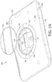
FIGS. 2A-B illustrate the protective case including an electronic device, according to an example. InFIG. 2A , aUSB dongle 202 is connected to thedevice 100. In particular,USB dongle 202 is located insecond recess 124 of thecavity 104, and is connected to theUSB connector 126. Because theUSB dongle 202 is in thecavity 104, a smart card may not be used simultaneously within thecavity 104. - In
FIG. 2B , asmart card 210 is connected to thedevice 100. In particular thesmart card 210 is located infirst recess 114 of thecavity 104, and is connected to thesmart card reader 116. Because thesmart card 210 is in thecavity 104, theUSB dongle 202 may not be used simultaneously in thecavity 104. -
Case 102 can further include a light emitting diode (LED) 204 to indicate that one of theUSB dongle 202 and asmart card 210 is present in the cavity. In some examples, theLED 204 may display a first color to indicate that theUSB dongle 202 is in use or present in thecavity 104 and a second color to indicate that thesmart card 210 is in use or present in thecavity 104.Case 102 can include one or more openings to reveal arear facing camera 206 and anearphone port 218 of thedevice 100. -
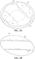
FIGS. 3A-B illustrate a cover of the protective case, according to an example. Cover 106 can be dome shaped or bulged such that thecover 106 accommodates the shape and length of theUSB dongle 202 while maintaining sufficient pressure on thesmart card 210 to provide contact with thesmart card reader 116. -
FIG. 3A illustrates aninner portion 316 of thecover 106. Theinner portion 316 is the portion facing theelectronic devices inner portion 316 of thecover 106 can include L-shaped locking features 310 to removably couple with corresponding L-shaped locking features of thecavity 104. To illustrate, the L-shaped locking features 310 of thecover 106 can rotate to lock or unlock thecover 106 from thecavity 104. Alternatively, or in addition,cover 106 can include magnets (not shown) disposed therein to removably couple with magnets disposed within thecavity 104. -
FIG. 3B illustrates anouter portion 326 of the cover (e.g., convex). In certain examples, thecover 106 includes anLED 336 on theouter portion 326. The LED can indicate when theUSB dongle 202 or thesmart card 210 is in use or inserted into thecavity 104. In some examples, theLED 336 can display a different color when theUSB dongle 202 is in use and when thesmart card 210 is in use. In other examples, thecover 106 is transparent such that a user can see through theouter portion 326 if one of theUSB dongle 202 and thesmart card 210 is in thecavity 104. -
FIG. 4 illustrates the protective case including the cover coupled to the cavity of the case, according to an example. In the example ofFIG. 4 , thecover 106 coupled to thecavity 104 to protectelectronic devices cavity 104 from water and dust, for example while providing expanded functionality for thedevice 100. In the example ofFIG. 4 , thecase 102 can include twoopenings 420 on a surface portion of thecase 102 for attaching a strap (not shown). The strap can be useable for holding thedevice 100. Further, the surface portion 410 can rotate (for example via the strap) to change an orientation of thedevice 100. -
FIG. 5 illustrates the protective case including a strap across an outer surface portion of the case for holding and rotating the device, according to an example. In the example ofFIG. 5 , astrap 530 can be inserted into the twoopenings 420 on the outer surface portion 410 of thecase 102. The surface portion 410 can rotate clockwise and counter-clockwise to change an orientation of the device. Accordingly, a user can hold the device via thestrap 530 and rotate thedevice 100 during use, for comfort and convenience. - In the foregoing description, numerous details are set forth to provide an understanding of the present disclosure. However, it will be understood by those skilled in the art that the present disclosure may be practiced without these details. While the present disclosure has been disclosed with respect to a limited number of examples, those skilled in the art will appreciate numerous modifications and variations therefrom. The present invention is defined by the appended claims.
Claims (11)
- A protective case (102) for a portable computing device (100), the case (102) comprising:a cavity (104) in the case (102) to house a plurality of electronic devices (202, 210), the cavity (104) including:a first recess (114) to receive a first electronic device (210), anda second recess (124) to receive a second electronic device (202); and a cover (106) removably coupled to the cavity (104),wherein the first electronic device (210) includes a smart card (210) and wherein the second electronic device (202) includes a universal serial bus, USB, dongle (202),wherein the first recess (114) includes a smart card reader (116) to connect to the smart card (210) and wherein the second recess (124) includes a USB connector (126) to connect with the USB dongle (202),characterised in that the second recess (124) is located across the first recess (114) such that either one of the smart card (210) and the USB dongle (202) can be used at one time.
- The protective case (102) of claim 1, wherein the cavity is a round cavity and wherein an edge of the round cavity includes at least one of an O-ring and a round-shaped silicon rubber to protect the cavity from external environment.
- The protective case (102) of claim 1, wherein the smart card reader (116) and the USB connector (126) are connected to a printed circuit board (PCB) of the portable computing device (100).
- The protective case (102) of claim 1, wherein the cover (102) is dome shaped such that the cover accommodates a shape and length of the USB dongle (202) while maintaining sufficient pressure on the smart card (210) to provide contact with the smart card reader (116).
- The protective case (102) of claim 1, wherein the cavity (104) includes first L-shaped locking features (110) to removably couple with second L-shaped locking features (310) of the cover (106).
- The protective case (102) of claim 1, wherein the cavity includes first magnetic members to magnetically couple with second magnetic members disposed within the cover.
- The protective case (102) of one of claims 1 to 6, for enclosing a back surface and sidewalls of the portable computing device, wherein the cover (106) rotates to unlock the cover (106) from the case (102).
- The protective case (102) of claim 7, wherein the case (102) includes a light emitting diode, LED, (204) to indicate that one of the smart card (210) and the USB dongle (202) is present in the cavity (104).
- The protective case (102) of claim 7, wherein the case (102) includes two openings (420) on a surface portion (410) of the case (120) to attach a strap (530) to hold the portable computing device (100), and wherein the surface portion (410) is rotatable to change an orientation of the portable computing device (100).
- A system comprising:a portable computing device (100) including a display surface and a back surface opposite the display surface; anda protective case (102) according to claim 1 for enclosing the back surface and sidewalls of the portable computing device (100).
- The system of claim 10,
wherein the smart card reader (116) and the UBS connector (126) are connected to a printed circuit board assembly (PCBA) of the portable computing device (100), and
wherein a middle portion of the cover (106) is transparent to show a presence of the smart card (210) or the USB dongle (202) in the cavity.
Applications Claiming Priority (1)
| Application Number | Priority Date | Filing Date | Title |
|---|---|---|---|
| PCT/US2014/036189 WO2015167536A2 (en) | 2014-04-30 | 2014-04-30 | Protective case for a device |
Publications (3)
| Publication Number | Publication Date |
|---|---|
| EP3136900A2 EP3136900A2 (en) | 2017-03-08 |
| EP3136900A4 EP3136900A4 (en) | 2017-12-06 |
| EP3136900B1 true EP3136900B1 (en) | 2019-02-20 |
Family
ID=54359465
Family Applications (1)
| Application Number | Title | Priority Date | Filing Date |
|---|---|---|---|
| EP14890937.7A Not-in-force EP3136900B1 (en) | 2014-04-30 | 2014-04-30 | Protective case for a device |
Country Status (4)
| Country | Link |
|---|---|
| US (1) | US9980543B2 (en) |
| EP (1) | EP3136900B1 (en) |
| CN (1) | CN106455778A (en) |
| WO (1) | WO2015167536A2 (en) |
Families Citing this family (64)
| Publication number | Priority date | Publication date | Assignee | Title |
|---|---|---|---|---|
| US10824698B2 (en) * | 2011-11-29 | 2020-11-03 | Cardlogix | Multimode smart card system with embedded USB connectivity |
| USD747321S1 (en) * | 2013-07-02 | 2016-01-12 | Hand Held Products, Inc. | Electronic device enclosure |
| US9847805B2 (en) * | 2014-08-19 | 2017-12-19 | World Richman Manufacturing Corporation | Cradle-case combination with magnetic fastener feature |
| USD840988S1 (en) * | 2015-11-13 | 2019-02-19 | Spigen Korea Co., Ltd. | Case for electronic communications device |
| USD840989S1 (en) * | 2015-11-13 | 2019-02-19 | Spigen Korea Co., Ltd. | Case for electronic communications device |
| USD839858S1 (en) * | 2015-11-13 | 2019-02-05 | Spigen Korea Co., Ltd. | Case for electronic communications device |
| WO2019089860A1 (en) * | 2017-10-31 | 2019-05-09 | In Esther | Protective case for mobile device |
| USD952623S1 (en) * | 2017-11-06 | 2022-05-24 | Securegrip, Llc | Phone case |
| US10244854B1 (en) * | 2018-01-12 | 2019-04-02 | Tzumi Electronics LLC | Gripping apparatus for handheld devices |
| USD897348S1 (en) * | 2018-08-01 | 2020-09-29 | Shenzhen Lanbo Technology Co., Ltd. | Tablet case |
| USD892804S1 (en) * | 2019-06-14 | 2020-08-11 | Guangzhou Roiskin Electrical Technology Co. Ltd | Tablet case |
| USD926748S1 (en) | 2019-06-14 | 2021-08-03 | Nlu Products, L.L.C. | Wristband connector for mobile device |
| USD942456S1 (en) * | 2019-12-30 | 2022-02-01 | Shenzhen Lanbo Technology Co., Ltd. | Portable electronic device case |
| USD962214S1 (en) * | 2020-08-05 | 2022-08-30 | Apple Inc. | Case for an electronic device |
| USD962215S1 (en) | 2020-08-05 | 2022-08-30 | Apple Inc. | Case for an electronic device |
| USD948492S1 (en) * | 2020-08-05 | 2022-04-12 | Apple Inc. | Case for an electronic device |
| USD944256S1 (en) * | 2020-09-21 | 2022-02-22 | Fang Cheng | Tablet case |
| USD1002630S1 (en) * | 2020-10-23 | 2023-10-24 | Spigen Korea Co., Ltd. | Case for electonic device |
| CN114448459A (en) * | 2020-11-05 | 2022-05-06 | 盛微先进科技股份有限公司 | Detachable wireless audio transmission system |
| USD949153S1 (en) * | 2020-11-09 | 2022-04-19 | Xiaoqing Chen | Protective cover for tablet computer |
| US12035798B2 (en) * | 2020-12-11 | 2024-07-16 | Beren McKay | Implement holder |
| USD1006816S1 (en) * | 2020-12-17 | 2023-12-05 | Spigen Korea Co., Ltd. | Case for electronic device |
| USD937275S1 (en) * | 2021-01-08 | 2021-11-30 | Ganhua Cheng | Tablet case |
| USD946579S1 (en) * | 2021-04-26 | 2022-03-22 | Fengqin Tan | Tablet case |
| USD946578S1 (en) * | 2021-04-26 | 2022-03-22 | Ganhua Cheng | Tablet case |
| USD981418S1 (en) * | 2021-07-01 | 2023-03-21 | Guangzhou Roiskin Technology Company | Tablet case |
| USD1013693S1 (en) * | 2021-07-01 | 2024-02-06 | Spigen Korea Co., Ltd. | Case for electronic device |
| USD1016073S1 (en) * | 2021-07-06 | 2024-02-27 | Spigen Korea Co., Ltd. | Case for electronic device |
| USD1022647S1 (en) * | 2021-08-12 | 2024-04-16 | Shenzhen Carku Technology Co., Limited | Electric wrench |
| USD1043300S1 (en) * | 2021-09-25 | 2024-09-24 | Atlas Copco Industrial Technique Ab | Power tool |
| USD963655S1 (en) * | 2021-10-09 | 2022-09-13 | Shiyong Ding | Tablet cover |
| USD967829S1 (en) * | 2021-11-18 | 2022-10-25 | Guangzhou Roiskin Technology Company | Tablet case |
| USD970510S1 (en) * | 2021-11-24 | 2022-11-22 | Guangzhou Huiyue Electronic Technology Co., Ltd. | Tablet case |
| US12706469B2 (en) | 2021-12-17 | 2026-08-11 | Annex Products Pty. Ltd. | Wireless charger assembly for a cellphone |
| US12531435B2 (en) | 2021-12-17 | 2026-01-20 | Annex Products Pty. Ltd. | Wireless charger mounting system |
| USD967830S1 (en) * | 2022-01-13 | 2022-10-25 | Guangzhou Huiyue Electronic Technology Co., Ltd. | Tablet case |
| USD1023711S1 (en) * | 2022-01-31 | 2024-04-23 | Nemo Power Tools Limited | Vacuum drill press |
| USD1016820S1 (en) * | 2022-03-17 | 2024-03-05 | Guangzhou Roiskin Technology Company | Tablet case |
| USD1026919S1 (en) * | 2022-04-15 | 2024-05-14 | Liangwu Hu | Tablet case |
| USD964374S1 (en) * | 2022-05-30 | 2022-09-20 | Huimin Zhou | Tablet rotatable case |
| USD964373S1 (en) * | 2022-05-30 | 2022-09-20 | Huimin Zhou | Tablet rotatable case |
| USD967115S1 (en) * | 2022-06-22 | 2022-10-18 | Fuyue Zeng | Tablet case |
| USD1024049S1 (en) | 2022-06-28 | 2024-04-23 | Annex Products Pty Ltd | Mounting head |
| USD1087942S1 (en) | 2022-06-28 | 2025-08-12 | Annex Products Pty. Ltd. | Case for mobile electronic device |
| USD1024048S1 (en) | 2022-06-28 | 2024-04-23 | Annex Products Pty Ltd | Mounting head |
| USD1028964S1 (en) | 2022-06-29 | 2024-05-28 | Annex Products Pty Ltd | Desk stand |
| USD1103998S1 (en) * | 2022-11-08 | 2025-12-02 | Shenzhen Lanhe Technologies Co., Ltd. | Case for electronic device |
| USD985000S1 (en) * | 2022-11-21 | 2023-05-02 | Guangzhou Huiyue Technology Development Co., Ltd. | Tablet case |
| USD978154S1 (en) * | 2022-12-05 | 2023-02-14 | Bo Gao | Tablet computer protective casing |
| USD983802S1 (en) * | 2022-12-05 | 2023-04-18 | Guangzhou Huiyue Technology Development Co., Ltd. | Tablet case |
| USD978868S1 (en) * | 2022-12-05 | 2023-02-21 | Jiawei Gao | Tablet cover |
| USD1071839S1 (en) | 2023-03-10 | 2025-04-22 | Annex Products Pty. Ltd. | Battery attachment |
| USD1076425S1 (en) | 2023-03-16 | 2025-05-27 | Annex Products Pty. Ltd. | Wallet attachment |
| US20240385653A1 (en) * | 2023-05-16 | 2024-11-21 | JACS Solutions | Protective structures for computer dongles |
| US11815950B2 (en) | 2023-06-09 | 2023-11-14 | Guangdong Shuowei Technology Co., Ltd. | Clamshell tablet protective case |
| USD1024081S1 (en) * | 2023-06-12 | 2024-04-23 | Hongge ZHANG | Tablet case |
| USD1042467S1 (en) * | 2024-01-25 | 2024-09-17 | Guangzhou wieershi Electronics Technology Co., Ltd. | Protective case for tablet |
| US12656841B2 (en) * | 2024-02-02 | 2026-06-16 | Joseph Leo Wesley | Cooling case for electronic device |
| USD1067915S1 (en) * | 2024-04-10 | 2025-03-25 | Foshan Lzb Technology Co., Ltd. | Tablet case |
| US12601448B2 (en) * | 2024-08-12 | 2026-04-14 | Shenzhen Taersen Technology Co., Ltd. | Mobile terminal protective holder |
| USD1119880S1 (en) | 2024-09-06 | 2026-03-24 | Apple Inc. | Case for an electronic device |
| USD1122236S1 (en) | 2024-09-09 | 2026-04-14 | Apple Inc. | Case for an electronic device |
| USD1139254S1 (en) | 2024-09-09 | 2026-08-04 | Apple Inc. | Case for an electronic device |
| USD1099086S1 (en) * | 2025-01-17 | 2025-10-21 | Casetagram Limited | Mobile phone case |
Family Cites Families (21)
| Publication number | Priority date | Publication date | Assignee | Title |
|---|---|---|---|---|
| US7440286B2 (en) | 2005-04-21 | 2008-10-21 | Super Talent Electronics, Inc. | Extended USB dual-personality card reader |
| US20070032122A1 (en) * | 2005-08-03 | 2007-02-08 | 3 View Technology Co., Ltd | Electronic device with USB storage card |
| JP4741456B2 (en) | 2006-12-27 | 2011-08-03 | 株式会社リコー | Image processing apparatus and information processing apparatus |
| CN201072558Y (en) * | 2007-09-04 | 2008-06-11 | 靳兆竣 | Built-in card reader |
| US7651346B2 (en) | 2008-05-06 | 2010-01-26 | Delphi Technologies, Inc. | Communication port |
| CN201251930Y (en) | 2008-09-12 | 2009-06-03 | 深圳创维-Rgb电子有限公司 | Vehicle-carrying multimedia player with double USB and an SD card plug jack |
| CN101931670A (en) * | 2009-06-25 | 2010-12-29 | 深圳富泰宏精密工业有限公司 | Portable electronic device |
| KR20100089017A (en) * | 2009-12-29 | 2010-08-11 | 이창주 | Cellular phone battery cover |
| KR101255986B1 (en) * | 2010-12-28 | 2013-04-17 | (주)엠씨페이 | cellular phone cover for protection |
| WO2011081448A2 (en) * | 2009-12-29 | 2011-07-07 | Lee Chang-Ju | Cover for rear side of mobile phone |
| US20120103855A1 (en) * | 2010-06-07 | 2012-05-03 | 360 Mobility Solutions, Llc | Cases for electronic devices |
| US20120154119A1 (en) * | 2010-12-20 | 2012-06-21 | Michael Lee Schepps | Interactive personal property location system |
| CN202103291U (en) * | 2011-05-16 | 2012-01-04 | 江汉中 | Transition structure |
| KR101285414B1 (en) | 2011-06-23 | 2013-07-11 | (주)탑나노시스 | Method for manufacturing carbon nano tube film with pattern |
| KR200470353Y1 (en) * | 2011-07-12 | 2013-12-11 | 주희원 | Protection case for smart phone |
| GB2500046B (en) | 2012-03-08 | 2014-03-19 | Bll Holdings Ltd | Storage apparatus |
| US9241551B2 (en) * | 2012-06-13 | 2016-01-26 | Otter Products, Llc | Protective case with compartment |
| CN203340121U (en) * | 2013-01-25 | 2013-12-11 | 深圳市天码汇科技有限公司 | Slid mobile phone protective housing with function of storing cards |
| KR101386854B1 (en) * | 2013-03-28 | 2014-04-18 | 이진우 | Case having function of keeping memory apparatus |
| US20140364176A1 (en) * | 2013-06-06 | 2014-12-11 | Daniel Pintor | Phone case with movable strap and cover |
| US20150102073A1 (en) * | 2013-10-14 | 2015-04-16 | Julie Pusateri | Cases for electronic devices |
-
2014
- 2014-04-30 EP EP14890937.7A patent/EP3136900B1/en not_active Not-in-force
- 2014-04-30 CN CN201480078552.2A patent/CN106455778A/en active Pending
- 2014-04-30 WO PCT/US2014/036189 patent/WO2015167536A2/en not_active Ceased
- 2014-04-30 US US15/304,935 patent/US9980543B2/en not_active Expired - Fee Related
Non-Patent Citations (1)
| Title |
|---|
| None * |
Also Published As
| Publication number | Publication date |
|---|---|
| WO2015167536A3 (en) | 2016-04-28 |
| EP3136900A4 (en) | 2017-12-06 |
| US20170196327A1 (en) | 2017-07-13 |
| WO2015167536A2 (en) | 2015-11-05 |
| EP3136900A2 (en) | 2017-03-08 |
| US9980543B2 (en) | 2018-05-29 |
| CN106455778A (en) | 2017-02-22 |
Similar Documents
| Publication | Publication Date | Title |
|---|---|---|
| US9980543B2 (en) | Protective case for a device | |
| US9529387B2 (en) | Docking sleeve with electrical adapter | |
| CN107436627B (en) | Electronic equipment with sealing member | |
| US9348371B2 (en) | Protective case for a portable computing device | |
| CN113395077A (en) | Portable electronic device | |
| US9853349B2 (en) | Electronic device | |
| US20160062414A1 (en) | Electronic device and apparatus | |
| EP3175315B1 (en) | Protective jacket for a device | |
| KR101386854B1 (en) | Case having function of keeping memory apparatus | |
| JP5355751B1 (en) | Electronic device and control method of electronic device | |
| US10043114B2 (en) | Electronic device | |
| CN104582384A (en) | Electronic assembly and electronic device | |
| KR200476664Y1 (en) | Case for protecting portable terminal | |
| US20170277924A1 (en) | Protective case with barcode scanner | |
| US20140210720A1 (en) | Mouse device | |
| US20130164985A1 (en) | Universal serial bus connector | |
| EP3186689B1 (en) | Protective jacket with a kickstand | |
| US20120257367A1 (en) | Protective jacket and wireless communication device using the same | |
| US20120140393A1 (en) | Protective case | |
| US8873234B2 (en) | Computer host with a rotatable socket mechanism | |
| JP3176968U (en) | USB charging hub | |
| TWI458207B (en) | Flash memory device | |
| CN216014104U (en) | Notebook computer | |
| JP5930529B2 (en) | Electronic equipment | |
| TWM576773U (en) | Cap structure for USB flash drive |
Legal Events
| Date | Code | Title | Description |
|---|---|---|---|
| STAA | Information on the status of an ep patent application or granted ep patent |
Free format text: STATUS: THE INTERNATIONAL PUBLICATION HAS BEEN MADE |
|
| PUAI | Public reference made under article 153(3) epc to a published international application that has entered the european phase |
Free format text: ORIGINAL CODE: 0009012 |
|
| STAA | Information on the status of an ep patent application or granted ep patent |
Free format text: STATUS: REQUEST FOR EXAMINATION WAS MADE |
|
| 17P | Request for examination filed |
Effective date: 20161025 |
|
| AK | Designated contracting states |
Kind code of ref document: A2 Designated state(s): AL AT BE BG CH CY CZ DE DK EE ES FI FR GB GR HR HU IE IS IT LI LT LU LV MC MK MT NL NO PL PT RO RS SE SI SK SM TR |
|
| AX | Request for extension of the european patent |
Extension state: BA ME |
|
| RIN1 | Information on inventor provided before grant (corrected) |
Inventor name: WIDIAMAN, RUDY Inventor name: THORNTON, KYLE ROBERT Inventor name: MA, XIANG Inventor name: ALI-NAPO, CARLA |
|
| DAX | Request for extension of the european patent (deleted) | ||
| A4 | Supplementary search report drawn up and despatched |
Effective date: 20171107 |
|
| RIC1 | Information provided on ipc code assigned before grant |
Ipc: A45C 11/00 20060101AFI20171030BHEP Ipc: H05K 5/02 20060101ALI20171030BHEP Ipc: G06F 1/18 20060101ALI20171030BHEP |
|
| RIN1 | Information on inventor provided before grant (corrected) |
Inventor name: MA, XIANG Inventor name: THORNTON, KYLE ROBERT Inventor name: WIDIAMAN, RUDY Inventor name: ALI-NAPO, CARLA |
|
| GRAP | Despatch of communication of intention to grant a patent |
Free format text: ORIGINAL CODE: EPIDOSNIGR1 |
|
| STAA | Information on the status of an ep patent application or granted ep patent |
Free format text: STATUS: GRANT OF PATENT IS INTENDED |
|
| INTG | Intention to grant announced |
Effective date: 20181105 |
|
| GRAS | Grant fee paid |
Free format text: ORIGINAL CODE: EPIDOSNIGR3 |
|
| GRAA | (expected) grant |
Free format text: ORIGINAL CODE: 0009210 |
|
| STAA | Information on the status of an ep patent application or granted ep patent |
Free format text: STATUS: THE PATENT HAS BEEN GRANTED |
|
| AK | Designated contracting states |
Kind code of ref document: B1 Designated state(s): AL AT BE BG CH CY CZ DE DK EE ES FI FR GB GR HR HU IE IS IT LI LT LU LV MC MK MT NL NO PL PT RO RS SE SI SK SM TR |
|
| REG | Reference to a national code |
Ref country code: GB Ref legal event code: FG4D |
|
| REG | Reference to a national code |
Ref country code: CH Ref legal event code: EP |
|
| REG | Reference to a national code |
Ref country code: DE Ref legal event code: R096 Ref document number: 602014041596 Country of ref document: DE |
|
| REG | Reference to a national code |
Ref country code: AT Ref legal event code: REF Ref document number: 1097053 Country of ref document: AT Kind code of ref document: T Effective date: 20190315 |
|
| REG | Reference to a national code |
Ref country code: IE Ref legal event code: FG4D |
|
| RAP2 | Party data changed (patent owner data changed or rights of a patent transferred) |
Owner name: HEWLETT-PACKARD DEVELOPMENT COMPANY, L.P. |
|
| REG | Reference to a national code |
Ref country code: NL Ref legal event code: MP Effective date: 20190220 |
|
| REG | Reference to a national code |
Ref country code: LT Ref legal event code: MG4D |
|
| PG25 | Lapsed in a contracting state [announced via postgrant information from national office to epo] |
Ref country code: LT Free format text: LAPSE BECAUSE OF FAILURE TO SUBMIT A TRANSLATION OF THE DESCRIPTION OR TO PAY THE FEE WITHIN THE PRESCRIBED TIME-LIMIT Effective date: 20190220 Ref country code: SE Free format text: LAPSE BECAUSE OF FAILURE TO SUBMIT A TRANSLATION OF THE DESCRIPTION OR TO PAY THE FEE WITHIN THE PRESCRIBED TIME-LIMIT Effective date: 20190220 Ref country code: NL Free format text: LAPSE BECAUSE OF FAILURE TO SUBMIT A TRANSLATION OF THE DESCRIPTION OR TO PAY THE FEE WITHIN THE PRESCRIBED TIME-LIMIT Effective date: 20190220 Ref country code: PT Free format text: LAPSE BECAUSE OF FAILURE TO SUBMIT A TRANSLATION OF THE DESCRIPTION OR TO PAY THE FEE WITHIN THE PRESCRIBED TIME-LIMIT Effective date: 20190620 Ref country code: NO Free format text: LAPSE BECAUSE OF FAILURE TO SUBMIT A TRANSLATION OF THE DESCRIPTION OR TO PAY THE FEE WITHIN THE PRESCRIBED TIME-LIMIT Effective date: 20190520 Ref country code: FI Free format text: LAPSE BECAUSE OF FAILURE TO SUBMIT A TRANSLATION OF THE DESCRIPTION OR TO PAY THE FEE WITHIN THE PRESCRIBED TIME-LIMIT Effective date: 20190220 |
|
| PG25 | Lapsed in a contracting state [announced via postgrant information from national office to epo] |
Ref country code: IS Free format text: LAPSE BECAUSE OF FAILURE TO SUBMIT A TRANSLATION OF THE DESCRIPTION OR TO PAY THE FEE WITHIN THE PRESCRIBED TIME-LIMIT Effective date: 20190620 Ref country code: BG Free format text: LAPSE BECAUSE OF FAILURE TO SUBMIT A TRANSLATION OF THE DESCRIPTION OR TO PAY THE FEE WITHIN THE PRESCRIBED TIME-LIMIT Effective date: 20190520 Ref country code: RS Free format text: LAPSE BECAUSE OF FAILURE TO SUBMIT A TRANSLATION OF THE DESCRIPTION OR TO PAY THE FEE WITHIN THE PRESCRIBED TIME-LIMIT Effective date: 20190220 Ref country code: LV Free format text: LAPSE BECAUSE OF FAILURE TO SUBMIT A TRANSLATION OF THE DESCRIPTION OR TO PAY THE FEE WITHIN THE PRESCRIBED TIME-LIMIT Effective date: 20190220 Ref country code: GR Free format text: LAPSE BECAUSE OF FAILURE TO SUBMIT A TRANSLATION OF THE DESCRIPTION OR TO PAY THE FEE WITHIN THE PRESCRIBED TIME-LIMIT Effective date: 20190521 Ref country code: HR Free format text: LAPSE BECAUSE OF FAILURE TO SUBMIT A TRANSLATION OF THE DESCRIPTION OR TO PAY THE FEE WITHIN THE PRESCRIBED TIME-LIMIT Effective date: 20190220 |
|
| REG | Reference to a national code |
Ref country code: AT Ref legal event code: MK05 Ref document number: 1097053 Country of ref document: AT Kind code of ref document: T Effective date: 20190220 |
|
| PG25 | Lapsed in a contracting state [announced via postgrant information from national office to epo] |
Ref country code: ES Free format text: LAPSE BECAUSE OF FAILURE TO SUBMIT A TRANSLATION OF THE DESCRIPTION OR TO PAY THE FEE WITHIN THE PRESCRIBED TIME-LIMIT Effective date: 20190220 Ref country code: DK Free format text: LAPSE BECAUSE OF FAILURE TO SUBMIT A TRANSLATION OF THE DESCRIPTION OR TO PAY THE FEE WITHIN THE PRESCRIBED TIME-LIMIT Effective date: 20190220 Ref country code: SK Free format text: LAPSE BECAUSE OF FAILURE TO SUBMIT A TRANSLATION OF THE DESCRIPTION OR TO PAY THE FEE WITHIN THE PRESCRIBED TIME-LIMIT Effective date: 20190220 Ref country code: AL Free format text: LAPSE BECAUSE OF FAILURE TO SUBMIT A TRANSLATION OF THE DESCRIPTION OR TO PAY THE FEE WITHIN THE PRESCRIBED TIME-LIMIT Effective date: 20190220 Ref country code: EE Free format text: LAPSE BECAUSE OF FAILURE TO SUBMIT A TRANSLATION OF THE DESCRIPTION OR TO PAY THE FEE WITHIN THE PRESCRIBED TIME-LIMIT Effective date: 20190220 Ref country code: IT Free format text: LAPSE BECAUSE OF FAILURE TO SUBMIT A TRANSLATION OF THE DESCRIPTION OR TO PAY THE FEE WITHIN THE PRESCRIBED TIME-LIMIT Effective date: 20190220 Ref country code: RO Free format text: LAPSE BECAUSE OF FAILURE TO SUBMIT A TRANSLATION OF THE DESCRIPTION OR TO PAY THE FEE WITHIN THE PRESCRIBED TIME-LIMIT Effective date: 20190220 Ref country code: CZ Free format text: LAPSE BECAUSE OF FAILURE TO SUBMIT A TRANSLATION OF THE DESCRIPTION OR TO PAY THE FEE WITHIN THE PRESCRIBED TIME-LIMIT Effective date: 20190220 |
|
| REG | Reference to a national code |
Ref country code: DE Ref legal event code: R097 Ref document number: 602014041596 Country of ref document: DE |
|
| PG25 | Lapsed in a contracting state [announced via postgrant information from national office to epo] |
Ref country code: SM Free format text: LAPSE BECAUSE OF FAILURE TO SUBMIT A TRANSLATION OF THE DESCRIPTION OR TO PAY THE FEE WITHIN THE PRESCRIBED TIME-LIMIT Effective date: 20190220 Ref country code: PL Free format text: LAPSE BECAUSE OF FAILURE TO SUBMIT A TRANSLATION OF THE DESCRIPTION OR TO PAY THE FEE WITHIN THE PRESCRIBED TIME-LIMIT Effective date: 20190220 |
|
| REG | Reference to a national code |
Ref country code: CH Ref legal event code: PL |
|
| REG | Reference to a national code |
Ref country code: BE Ref legal event code: MM Effective date: 20190430 |
|
| PLBE | No opposition filed within time limit |
Free format text: ORIGINAL CODE: 0009261 |
|
| STAA | Information on the status of an ep patent application or granted ep patent |
Free format text: STATUS: NO OPPOSITION FILED WITHIN TIME LIMIT |
|
| PG25 | Lapsed in a contracting state [announced via postgrant information from national office to epo] |
Ref country code: MC Free format text: LAPSE BECAUSE OF FAILURE TO SUBMIT A TRANSLATION OF THE DESCRIPTION OR TO PAY THE FEE WITHIN THE PRESCRIBED TIME-LIMIT Effective date: 20190220 Ref country code: LU Free format text: LAPSE BECAUSE OF NON-PAYMENT OF DUE FEES Effective date: 20190430 Ref country code: AT Free format text: LAPSE BECAUSE OF FAILURE TO SUBMIT A TRANSLATION OF THE DESCRIPTION OR TO PAY THE FEE WITHIN THE PRESCRIBED TIME-LIMIT Effective date: 20190220 |
|
| 26N | No opposition filed |
Effective date: 20191121 |
|
| PG25 | Lapsed in a contracting state [announced via postgrant information from national office to epo] |
Ref country code: CH Free format text: LAPSE BECAUSE OF NON-PAYMENT OF DUE FEES Effective date: 20190430 Ref country code: LI Free format text: LAPSE BECAUSE OF NON-PAYMENT OF DUE FEES Effective date: 20190430 |
|
| PG25 | Lapsed in a contracting state [announced via postgrant information from national office to epo] |
Ref country code: FR Free format text: LAPSE BECAUSE OF NON-PAYMENT OF DUE FEES Effective date: 20190430 Ref country code: BE Free format text: LAPSE BECAUSE OF NON-PAYMENT OF DUE FEES Effective date: 20190430 Ref country code: SI Free format text: LAPSE BECAUSE OF FAILURE TO SUBMIT A TRANSLATION OF THE DESCRIPTION OR TO PAY THE FEE WITHIN THE PRESCRIBED TIME-LIMIT Effective date: 20190220 |
|
| PG25 | Lapsed in a contracting state [announced via postgrant information from national office to epo] |
Ref country code: TR Free format text: LAPSE BECAUSE OF FAILURE TO SUBMIT A TRANSLATION OF THE DESCRIPTION OR TO PAY THE FEE WITHIN THE PRESCRIBED TIME-LIMIT Effective date: 20190220 |
|
| PG25 | Lapsed in a contracting state [announced via postgrant information from national office to epo] |
Ref country code: IE Free format text: LAPSE BECAUSE OF NON-PAYMENT OF DUE FEES Effective date: 20190430 |
|
| PG25 | Lapsed in a contracting state [announced via postgrant information from national office to epo] |
Ref country code: CY Free format text: LAPSE BECAUSE OF FAILURE TO SUBMIT A TRANSLATION OF THE DESCRIPTION OR TO PAY THE FEE WITHIN THE PRESCRIBED TIME-LIMIT Effective date: 20190220 |
|
| PG25 | Lapsed in a contracting state [announced via postgrant information from national office to epo] |
Ref country code: HU Free format text: LAPSE BECAUSE OF FAILURE TO SUBMIT A TRANSLATION OF THE DESCRIPTION OR TO PAY THE FEE WITHIN THE PRESCRIBED TIME-LIMIT; INVALID AB INITIO Effective date: 20140430 Ref country code: MT Free format text: LAPSE BECAUSE OF FAILURE TO SUBMIT A TRANSLATION OF THE DESCRIPTION OR TO PAY THE FEE WITHIN THE PRESCRIBED TIME-LIMIT Effective date: 20190220 |
|
| PGFP | Annual fee paid to national office [announced via postgrant information from national office to epo] |
Ref country code: GB Payment date: 20220323 Year of fee payment: 9 |
|
| PG25 | Lapsed in a contracting state [announced via postgrant information from national office to epo] |
Ref country code: MK Free format text: LAPSE BECAUSE OF FAILURE TO SUBMIT A TRANSLATION OF THE DESCRIPTION OR TO PAY THE FEE WITHIN THE PRESCRIBED TIME-LIMIT Effective date: 20190220 |
|
| PGFP | Annual fee paid to national office [announced via postgrant information from national office to epo] |
Ref country code: DE Payment date: 20220322 Year of fee payment: 9 |
|
| REG | Reference to a national code |
Ref country code: DE Ref legal event code: R119 Ref document number: 602014041596 Country of ref document: DE |
|
| GBPC | Gb: european patent ceased through non-payment of renewal fee |
Effective date: 20230430 |
|
| PG25 | Lapsed in a contracting state [announced via postgrant information from national office to epo] |
Ref country code: GB Free format text: LAPSE BECAUSE OF NON-PAYMENT OF DUE FEES Effective date: 20230430 |
|
| PG25 | Lapsed in a contracting state [announced via postgrant information from national office to epo] |
Ref country code: GB Free format text: LAPSE BECAUSE OF NON-PAYMENT OF DUE FEES Effective date: 20230430 Ref country code: DE Free format text: LAPSE BECAUSE OF NON-PAYMENT OF DUE FEES Effective date: 20231103 |