EP3136821A1 - Method and device for heating a tank of an induction cooking equipment - Google Patents
Method and device for heating a tank of an induction cooking equipment Download PDFInfo
- Publication number
- EP3136821A1 EP3136821A1 EP16173705.1A EP16173705A EP3136821A1 EP 3136821 A1 EP3136821 A1 EP 3136821A1 EP 16173705 A EP16173705 A EP 16173705A EP 3136821 A1 EP3136821 A1 EP 3136821A1
- Authority
- EP
- European Patent Office
- Prior art keywords
- tank
- material type
- induction cooking
- barcode
- cooking equipment
- Prior art date
- Legal status (The legal status is an assumption and is not a legal conclusion. Google has not performed a legal analysis and makes no representation as to the accuracy of the status listed.)
- Granted
Links
Images



Classifications
-
- A—HUMAN NECESSITIES
- A47—FURNITURE; DOMESTIC ARTICLES OR APPLIANCES; COFFEE MILLS; SPICE MILLS; SUCTION CLEANERS IN GENERAL
- A47J—KITCHEN EQUIPMENT; COFFEE MILLS; SPICE MILLS; APPARATUS FOR MAKING BEVERAGES
- A47J27/00—Cooking-vessels
- A47J27/004—Cooking-vessels with integral electrical heating means
-
- A—HUMAN NECESSITIES
- A47—FURNITURE; DOMESTIC ARTICLES OR APPLIANCES; COFFEE MILLS; SPICE MILLS; SUCTION CLEANERS IN GENERAL
- A47J—KITCHEN EQUIPMENT; COFFEE MILLS; SPICE MILLS; APPARATUS FOR MAKING BEVERAGES
- A47J36/00—Parts, details or accessories of cooking-vessels
-
- G—PHYSICS
- G06—COMPUTING OR CALCULATING; COUNTING
- G06K—GRAPHICAL DATA READING; PRESENTATION OF DATA; RECORD CARRIERS; HANDLING RECORD CARRIERS
- G06K7/00—Methods or arrangements for sensing record carriers, e.g. for reading patterns
- G06K7/10—Methods or arrangements for sensing record carriers, e.g. for reading patterns by electromagnetic radiation, e.g. optical sensing; by corpuscular radiation
- G06K7/10009—Methods or arrangements for sensing record carriers, e.g. for reading patterns by electromagnetic radiation, e.g. optical sensing; by corpuscular radiation sensing by radiation using wavelengths larger than 0.1 mm, e.g. radio-waves or microwaves
- G06K7/10366—Methods or arrangements for sensing record carriers, e.g. for reading patterns by electromagnetic radiation, e.g. optical sensing; by corpuscular radiation sensing by radiation using wavelengths larger than 0.1 mm, e.g. radio-waves or microwaves the interrogation device being adapted for miscellaneous applications
-
- G—PHYSICS
- G06—COMPUTING OR CALCULATING; COUNTING
- G06K—GRAPHICAL DATA READING; PRESENTATION OF DATA; RECORD CARRIERS; HANDLING RECORD CARRIERS
- G06K7/00—Methods or arrangements for sensing record carriers, e.g. for reading patterns
- G06K7/10—Methods or arrangements for sensing record carriers, e.g. for reading patterns by electromagnetic radiation, e.g. optical sensing; by corpuscular radiation
- G06K7/14—Methods or arrangements for sensing record carriers, e.g. for reading patterns by electromagnetic radiation, e.g. optical sensing; by corpuscular radiation using light without selection of wavelength, e.g. sensing reflected white light
- G06K7/1404—Methods for optical code recognition
- G06K7/1408—Methods for optical code recognition the method being specifically adapted for the type of code
- G06K7/1413—1D bar codes
-
- H—ELECTRICITY
- H05—ELECTRIC TECHNIQUES NOT OTHERWISE PROVIDED FOR
- H05B—ELECTRIC HEATING; ELECTRIC LIGHT SOURCES NOT OTHERWISE PROVIDED FOR; CIRCUIT ARRANGEMENTS FOR ELECTRIC LIGHT SOURCES, IN GENERAL
- H05B6/00—Heating by electric, magnetic or electromagnetic fields
- H05B6/02—Induction heating
- H05B6/06—Control, e.g. of temperature, of power
-
- H—ELECTRICITY
- H05—ELECTRIC TECHNIQUES NOT OTHERWISE PROVIDED FOR
- H05B—ELECTRIC HEATING; ELECTRIC LIGHT SOURCES NOT OTHERWISE PROVIDED FOR; CIRCUIT ARRANGEMENTS FOR ELECTRIC LIGHT SOURCES, IN GENERAL
- H05B6/00—Heating by electric, magnetic or electromagnetic fields
- H05B6/02—Induction heating
- H05B6/06—Control, e.g. of temperature, of power
- H05B6/062—Control, e.g. of temperature, of power for cooking plates or the like
-
- H—ELECTRICITY
- H05—ELECTRIC TECHNIQUES NOT OTHERWISE PROVIDED FOR
- H05B—ELECTRIC HEATING; ELECTRIC LIGHT SOURCES NOT OTHERWISE PROVIDED FOR; CIRCUIT ARRANGEMENTS FOR ELECTRIC LIGHT SOURCES, IN GENERAL
- H05B6/00—Heating by electric, magnetic or electromagnetic fields
- H05B6/02—Induction heating
- H05B6/10—Induction heating apparatus, other than furnaces, for specific applications
- H05B6/12—Cooking devices
-
- A—HUMAN NECESSITIES
- A23—FOODS OR FOODSTUFFS; TREATMENT THEREOF, NOT COVERED BY OTHER CLASSES
- A23V—INDEXING SCHEME RELATING TO FOODS, FOODSTUFFS OR NON-ALCOHOLIC BEVERAGES AND LACTIC OR PROPIONIC ACID BACTERIA USED IN FOODSTUFFS OR FOOD PREPARATION
- A23V2002/00—Food compositions, function of food ingredients or processes for food or foodstuffs
Definitions
- the present invention generally relates to the field of home furnishing electronic technology, and more particularly to a method and a device for heating a tank of an induction cooking equipment.
- a cooking equipment can heat the food by converting electric energy to heat energy so as to achieve the goal of cooking.
- performing electric-to-heat conversion by adopting "a heating plate” refers to transferring the heat to a tank in which the food are placed in a cooking equipment by the heating plate after heating the heating plate by electric energy, then heating the food by the tank.
- a heating plate has a simple structure and is easy to be controlled, the problems of uneven heating, poor temperature control accuracy and the like exist.
- the invention relates to a method for heating a tank of an induction cooking equipment, comprising: determining a material type of a tank; and selecting a voltage change curve matching with the material type for use in a cooking process of the induction cooking equipment which the tank belongs to.
- the step of determining a material type of the tank may include: acquiring the material type contained in a barcode graph on a surface of the tank.
- the step of acquiring the material type contained in a barcode graph on a surface of the tank may include: acquiring and analyzing the barcode graph to acquire the material type contained in the barcode graph; or receiving an assisting message sent by a mobile device, the assisting message comprising the material type of the tank; wherein, the material type is acquired by acquiring and analyzing the barcode graph by the mobile device.
- the step of determining a material type of the tank may include: receiving a notification message sent by an electronic label on the tank, the notification message comprising the material type of the tank.
- the step of determining a material type of the tank may include: detecting a physical structure of a surface of the tank by a detection structure in an equipment body of the induction cooking equipment after the tank is installed into the equipment body so as to determine the material type of the tank.
- the physical structure is a bulge structure on the bottom of the tank, the material type corresponding to the location of the bulge structure on the bottom of the tank;
- the detection structure is a plurality of sunken structures on the bottom of the inside of the equipment body, and the plurality of sunken structures matching with bulge structures corresponding to a plurality of material types respectively;
- the step of detecting a physical structure of the surface of the tank by a detection structure in an equipment body of the induction cooking equipment may include: determining a corresponding material type according to a sunken structure n the detection structure matching with a bulge structure on the bottom of the tank after the tank is installed into the equipment body of the induction cooking equipment.
- the voltage change curve is generated according to received configuration instructions or is downloaded from a server.
- the invention relates to a device for heating a tank of an induction cooking equipment, including: a determination unit configured to determine a material type of a tank; and a selection unit configured to select a voltage change curve matching with the material type for use in a cooking process of the induction cooking equipment which the tank belongs to.
- the determination unit may include: an acquisition sub-unit configured to acquire the material type contained in a barcode graph on a surface of the tank.
- the acquisition sub-unit may include an analysis module or a receiving module; wherein, the analysis module is configured to acquire and analyze the barcode graph to acquire the material type contained in the barcode graph; and the receiving module is configured to receive an assisting message sent by a mobile device, the assisting message comprising the material type of the tank; wherein, the material type is acquired by acquiring and analyzing the barcode graph by the mobile device.
- the analysis module is configured to acquire and analyze the barcode graph to acquire the material type contained in the barcode graph
- the receiving module is configured to receive an assisting message sent by a mobile device, the assisting message comprising the material type of the tank; wherein, the material type is acquired by acquiring and analyzing the barcode graph by the mobile device.
- the determination unit may include: a message receiving sub-unit configured to receive a notification message sent by an electronic label on the tank, the notification message comprising the material type of the tank.
- the determination unit may include: a type detection sub-unit configured to detect a physical structure of a surface of the tank by a detection structure in an equipment body of the induction cooking equipment after the tank is installed into the equipment body so as to determine the material type of the tank.
- the physical structure is a bulge structure on the bottom of the tank, the material type corresponding to the location of the bulge structure on the bottom of the tank;
- the detection structure is a plurality of sunken structures on the bottom of the inside of the equipment body, and the plurality of sunken structures matching with bulge structures corresponding to a plurality of material types respectively;
- the type detection sub-unit may include: a determination module configured to determine a corresponding material type according to a sunken structure in the detection structure matching with a bulge structure on the bottom of the tank after the tank is installed into the equipment body of the induction cooking equipment.
- the voltage change curve is generated according to received configuration instructions or is downloaded from a server.
- the invention relates to an electronic device, including: a processor and a memory for storing processor-executable instructions, wherein the processor is configured to: determine a material type of a tank; and select a voltage change curve matching with the material type for use in a cooking process of an induction cooking equipment which the tank belongs to.
- the steps of the method for heating a tank of an induction cooking equipment are determined by computer program instructions.
- the invention is also directed to a computer program for executing the steps of a method for heating a tank of an induction cooking equipment as described above when this program is executed by a computer.
- This program can use any programming language and take the form of source code, object code or a code intermediate between source code and object code, such as a partially compiled form, or any other desirable form.
- the invention is also directed to a computer-readable information medium containing instructions of a computer program as described above.
- the information medium can be any entity or device capable of storing the program.
- the support can include storage means such as a ROM, for example a CD ROM or a microelectronic circuit ROM, or magnetic storage means, for example a diskette (floppy disk) or a hard disk.
- the information medium can be an integrated circuit in which the program is incorporated, the circuit being adapted to execute the method in question or to be used in its execution.
- the technical solutions provided by embodiments of the present invention may include the following beneficial effects: by determining a material type of a tank, different material types of tanks can obtain same or similar heating result by selecting a voltage change curve matching with a material type of a tank, and an induction cooking equipment can be compatible with different material types of tanks.
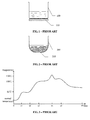
- Fig. 1 is a schematic diagram of heating a tank of an ordinary cooking equipment according to the prior art.
- the function of heating a tank 100 is achieved by adopting a heating plate 110.
- a heating plate may be equivalent to a resistor, and a heating plate can be heated when electric energy is outputted to the heating plate. Then the heating plate can transfer heat to a tank, and finally the tank can transfer heat to the food within the tank so as to achieve the heating and cooking of the food.
- an ordinary cooking equipment using a heating plate may cause the problems of uneven heating, poor temperature control accuracy and the like, this may affect cooking effect.
- an induction cooking equipment using Induction Heating is further provided in prior arts.
- high frequency alternating current may be transferred to electromagnetic coils 210 according to predefined voltage change curve, so that the electromagnetic coils may cause high frequency alternative magnetic field.
- the high frequency alternative magnetic field may drive microcrystalline structure in magnetic metal material in a tank 200 to generate vortex, so as to heat the food directly with heat through fiction among vortex generated by numerous microcrystalline structures.
- Fig. 3 shows a cooking curve actually required for the food as "rice” in the process of "cooking rice", the cooking curve may include: a pre-heating phase under normal temperature during the time period from 0 to t1; a water absorption phase under middle temperature of 60°C during the time period from t1 to t2; a heating phase under big fire that the temperature is heated to 100°C during the time period from t2 to t3; a boiling phase that the temperature is heated to 130°C during the time period from t3 to t4; a braising phase under high temperature during the time period from t4 to t5; a heat preservation phase during the time period from t5 to t6.
- the same cooking effect can be achieved if an induction cooking equipment can make the heat received by the "rice” in the cooking process of "cooking rice” conform to the cooking curve shown in Fig.3 .
- the same cooking effect can be achieved even if different tanks are used if it's ensured that the heating power of a tank in an induction cooking equipment always conform to the heat required for a cooking curve corresponding to current food and current cooking method.
- the value of the real voltage U should be determined according to the material type of a tank and the corresponding resistivity p, so as to different material types of tanks can generate the same heating power P.
- the resistivity p of material one is greater than the resistivity p of material two
- a larger voltage U1 is needed to be applied to the tank consist of material one
- a smaller voltage U2 is needed to be applied to the tank consist of material two, so that the two tanks can obtain the same heating power P at the same time point.
- different voltage change curves should be used when performing the same cooking operation on the same food, so as to ensure that the same cooking effect may be achieved.
- the induction cooking equipment in prior arts only takes into account the change of the food or cooking method, and does not take into account the support of different material types of tanks in a same induction cooking equipment, leading to that different material types of tanks always use same voltage change curve when performing the same cooking operation on the same food, thus leading to that the heat received by the food are different and may not always conform to the requirement of the heating curve shown in Fig. 3 .
- the present invention improves the heating process of an induction cooking equipment, so as to address above technical problems in prior arts.
- Fig. 5 is a flow chart illustrating a method for heating a tank of an induction cooking equipment according to an exemplary embodiment. As shown in Fig. 5 , the method is performed by an induction cooking equipment, and may include the following steps:
- different material types of tanks can obtain the same or similar heating result by selecting a voltage change curve matching with a material type of a tank, and an induction cooking equipment can be compatible with different material types of tanks.
- a material type of a tank may be identified by various methods. Several possible implementations thereof will be described in detail in the following. Of course, other methods capable of identifying a material type of a tank may be used in the embodiments of the present invention, and the present invention is not limited to the following methods.
- the material type of a tank contained in a barcode graph on a surface of the tank can be acquired.
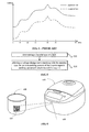
- a barcode graph (for example, two-dimension code 610, 710 shown in Figs. 6-7 ) is generated on an external surface of the tank (or any other positions such as a surface of a packing box of the tank) during the process of producing a tank by a manufacturer.
- the barcode graph contains the material type of the tank. As such, the material type of the tank can be read by collecting and identifying the barcode graph.
- each method may have a corresponding voltage change curve for various material types, so as to ensure that these material types of tanks can achieve same or similar cooking effect in the case of same cooking method. Therefore, after a material type of current tank is determined according to a barcode graph, a voltage change curve corresponding to the material type can be selected correctly, so that the heating power generated by the tank can conform to the heat required for the corresponding cooking curve.
- an induction cooking equipment can acquire and analyze a barcode graph on a tank directly, so as to acquire the material type of the tank contained in the barcode graph.
- an induction cooking equipment may be "an electric cooker", and a barcode graph on a tank may be "two-dimensional code”.
- a barcode graph 610 is printed or pasted on a surface of a tank 600, and the electric cooker 620 may be configured with a barcode identification device 630 such as a camera.
- the barcode identification device can collect the graph of a barcode graph and identify the material type contained in the graph by making the barcode graph towards to the barcode identification device.
- a material type of "100012” is acquired after identifying the barcode graph by the barcode identification device, for example, when the material type corresponding to "100012" is "material one”, then a voltage change curve corresponding to material one in Fig.4 should be used when the electric cooker selects the tank to perform a cooking operation of "cooking rice" on the "rice".
- an induction cooking equipment can receive an assisting message sent by a mobile device, the assisting message comprising the material type of the tank; wherein, the material type is acquired by acquiring and analyzing the barcode graph on the tank by the mobile device.
- an induction cooking equipment may be "an electric cooker"
- a mobile device may be a smart phone
- a barcode graph on a tank may be "two-dimensional code”.
- a barcode graph 710 is printed or pasted on a surface of a tank 700.
- the smart phone 740 can collect the graph of a barcode graph and identify the material type contained in the graph by a camera 720. Accordingly, the electric cooker 750 may not have to be configured with a barcode identification device such as a camera.
- the smart phone 740 and the electric cooker 750 should be configured with a communication module 1 (730) and a communication module 2 (760) respectively.
- the smart phone can send the type material "100012" to the electric cooker through the communication connection between the communication module 1 and the communication module 2. Then the electric cooker can know the material type of the tank and select a corresponding voltage change curve.
- an induction cooking equipment can receive a notification message sent by an electronic label on the tank, the notification message comprising the material type of the tank.
- an electronic label for example, RFID label shown in Figs. 8
- the electronic label contains the information on the material type of the tank. As such, the material type of the tank can be determined by activating the electronic label and receiving a notification message sent by the electronic label.
- an induction cooking equipment may be "an electric cooker", and an electronic label may be "RFID label”.
- a RFID label 810 may be disposed on a surface of the tank 800, the RFID label comprising the material type of the tank, and the electric cooker 820 may be configured with a RFID reader 830.
- making the RFID label enter the reading range of the RFID reader in the electric cooker can activate the RFID label, so as to receive a notification message sent by the RFID label, the notification message comprising the material type of the tank.
- a surface of a tank can be configured to have a physical structure corresponding to its own material type, then a physical structure of a surface of the tank can be detected by a detection structure in an equipment body of the induction cooking equipment after the tank is installed into the equipment body, so as to determine the material type of the tank.
- the "physical structure" of a tank may have various forms. Different material types of tanks need to correspond to different forms of physical structure, so as to distinguish among different material types of tanks clearly.
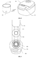
- the bulge structure 910 may be an annular bulge on the bottom of the tank 900, a material type of a tank corresponding to the location of the annular bulge on the bottom of the tank.
- the radiuses of the annular bulge corresponding to different material types of tank are different.
- the detection structure may be a plurality of sunken structures 920, 930 on the bottom of the inside of the equipment body 940, and the plurality of sunken structures matching with bulge structures corresponding to a plurality of material types respectively.
- the bottom of the inside of an equipment body shown in Fig. 9 may be configured with a first sunken structure having a smaller radius and a second sunken structure having a larger radius respectively.
- a bulge structure on the bottom of the tank can only match with one of the sunken structures on the bottom of the inside of the equipment body. Since the material type corresponding to each sunken structure is known, the material type of the tank can be determined by determining the sunken structure matching with the bulge structure. As shown in Fig. 9 , the bulge structure on the bottom of the tank corresponds to the first sunken structure in the equipment body, then it can be determined that the tank is made of "material one". Then a voltage change curve corresponding to material one in Fig.4 should be used when the electric cooker selects the tank to perform a cooking operation of "cooking rice" on the "rice".
- annular bulge structure and sunken structure users don't need to take into account the problems of installing direction and posture and the like and only need to make the bottom of the tank face down when putting the tank into the equipment body, so as to aim at the sunken structure 1 (930) directly without rotating to adjust in a horizontal direction, which may be useful for simplifying the user operation.
- a voltage change curve in an induction cooking equipment may be from a variety of sources.
- a voltage change curve may be pre-stored in an induction cooking equipment by a manufacturer.
- users can create a new voltage change curve according to the actual demand and import it into an induction cooking equipment.
- Users can also edit and adjust existing voltage change curve in an induction cooking equipment.
- Users can import new voltage change curve into an induction cooking equipment by creating or editing a voltage change curve on a mobile device after connecting to the induction cooking equipment by the mobile device such as a smart phone.
- an induction cooking equipment can be connected to Internet, so that the induction cooking equipment can download a voltage change curve from a server.
- the voltage change curve may be from a manufacturer, and may also be from other users, such as social friends of current user and the like.
- any methods capable of importing a voltage change curve into an induction cooking equipment may be used in the embodiments of the present invention, and the present invention is not limited to the above methods.
- the present invention further provides embodiments of a device for displaying information corresponding to the foregoing embodiments of a method for displaying information.
- Fig. 10 is a block diagram illustrating a device for heating a tank of an induction cooking equipment according to an exemplary embodiment.
- the device may include a determination unit 1001 and a selection unit 1002.
- the determination unit 1001 is configured to determine a material type of a tank; and the selection unit 1002 is configured to select a voltage change curve matching with the material type for use in a cooking process of the induction cooking equipment which the tank belongs to.
- the voltage change curve is generated according to received configuration instructions or is downloaded from a server.
- Fig. 11 is a block diagram illustrating another device for heating a tank of an induction cooking equipment according to an exemplary embodiment.
- the determination unit 1001 may include an acquisition sub-unit 1001A.
- the acquisition sub-unit 1001A is configured to acquire the material type contained in a barcode graph on a surface of the tank
- Fig. 12 is a block diagram illustrating another device for heating a tank of an induction cooking equipment according to an exemplary embodiment.
- the acquisition sub-unit 1001A may include an analysis module 1001A1 or a receiving module 1001A2.
- the analysis module 1001A1 is configured to acquire and analyze the barcode graph to acquire the material type contained in the barcode graph; and the receiving module 1001A2 is configured to receive an assisting message sent by a mobile device, the assisting message comprising the material type of the tank; wherein, the material type is acquired by acquiring and analyzing the barcode graph by the mobile device.
- Fig. 13 is a block diagram illustrating another device for heating a tank of an induction cooking equipment according to an exemplary embodiment.
- the determination unit 1001 may include a message receiving sub-unit 1001B.
- the message receiving sub-unit 1001B is configured to receive a notification message sent by an electronic label on the tank, the notification message comprising the material type of the tank.
- the message receiving sub-unit 1001B in embodiments of a device shown in Fig. 13 may be included in embodiments of a device shown in Figs. 11-12 , the present invention is not limited in the context.
- Fig. 14 is a block diagram illustrating another device for heating a tank of an induction cooking equipment according to an exemplary embodiment.
- the determination unit 1001 may include a type detection sub-unit 1001C.
- the type detection sub-unit 1001C is configured to detect a physical structure of a surface of the tank by a detection structure in an equipment body of the induction cooking equipment after the tank is installed into the equipment body so as to determine the material type of the tank.
- type detection sub-unit 1001C in embodiment of a device shown in Fig. 14 may be included in embodiments of a device shown in Figs. 11-13 , the present invention is not limited in the context.
- Fig. 15 is a block diagram illustrating another device for heating a tank of an induction cooking equipment according to an exemplary embodiment.
- the physical structure is a bulge structure on the bottom of the tank, the material type corresponding to the location of the bulge structure on the bottom of the tank;
- the detection structure is a plurality of sunken structures on the bottom of the inside of the equipment body, and the plurality of sunken structures matching with bulge structures corresponding to a plurality of material types respectively;
- the type detection sub-unit 1001C may include a determination module 1001C1.
- the determination module 1001C1 is configured to determine a corresponding material type according to a sunken structure in the detection structure matching with a bulge structure on the bottom of the tank after the tank is installed into the equipment body of the induction cooking equipment.
- the unit described as a separate component may be or may not be separate physically.
- the component shown as a unit may be or may not be a physical unit, namely, the component may be located in a place or may be distributed over a plurality of network units. Part or all of the modules can be selected according to actual demand, so as to achieve the goal of the solutions of the present invention.
- An ordinary skilled person in the art can appreciate and practice the embodiments without creative work.
- a device for heating a tank of an induction cooking equipment comprising: a processor; a memory for storing processor-executable instructions; wherein the processor is configured to: determine a material type of a tank; and select a voltage change curve matching with the material type for use in a cooking process of an induction cooking equipment which the tank belongs to.
- a terminal comprising: a memory; and one or more programs, wherein one or more programs are stored in the memory and are configured to be executed by one or more processors, one or more programs comprising instructions for performing the following operations: determining a material type of a tank; and selecting a voltage change curve matching with the material type for use in a cooking process of an induction cooking equipment which the tank belongs to.
- Fig. 16 is a block diagram of an device 1600 for heating a tank of an induction cooking equipment according to an exemplary embodiment.
- the device 1600 may be a mobile phone, a computer, a digital broadcast terminal, a messaging device, a gaming console, a tablet, a medical device, an exercise equipment, a personal digital assistant, and the like.
- the device 1600 may include one or more of the following components: a processing component 1602, a memory 1604, a power component 1606, a multimedia component 1608, an audio component 1610, an input/output (I/O) interface 1612, a sensor component 1614, and a communication component 1616.
- a processing component 1602 a memory 1604, a power component 1606, a multimedia component 1608, an audio component 1610, an input/output (I/O) interface 1612, a sensor component 1614, and a communication component 1616.
- the processing component 1602 typically controls overall operations of the device 1600, such as the operations associated with display, telephone calls, data communications, camera operations, and recording operations.
- the processing component 1602 may include one or more processors 1620 to execute instructions to perform all or part of the steps in the above described methods.
- the processing component 1602 may include one or more modules which facilitate the interaction between the processing component 1602 and other components.
- the processing component 1602 may include a multimedia module to facilitate the interaction between the multimedia component 1608 and the processing component 1602.
- the memory 1604 is configured to store various types of data to support the operation of the device 1600. Examples of such data include instructions for any applications or methods operated on the device 1600, contact data, phonebook data, messages, pictures, video, etc.
- the memory 1604 may be implemented using any type of volatile or non-volatile memory devices, or a combination thereof, such as a static random access memory (SRAM), an electrically erasable programmable read-only memory (EEPROM), an erasable programmable read-only memory (EPROM), a programmable read-only memory (PROM), a read-only memory (ROM), a magnetic memory, a flash memory, a magnetic or optical disk.
- SRAM static random access memory
- EEPROM electrically erasable programmable read-only memory
- EPROM erasable programmable read-only memory
- PROM programmable read-only memory
- ROM read-only memory
- magnetic memory a magnetic memory
- flash memory a flash memory
- magnetic or optical disk a magnetic or optical
- the power component 1606 provides power to various components of the device 1600.
- the power component 1606 may include a power management system, one or more power sources, and any other components associated with the generation, management, and distribution of power for the device 1600.
- the multimedia component 1608 includes a screen providing an output interface between the device 1600 and the user.
- the screen may include a liquid crystal display (LCD) and a touch panel (TP). If the screen includes the touch panel, the screen may be implemented as a touch screen to receive input signals from the user.
- the touch panel includes one or more touch sensors to sense touches, swipes, and gestures on the touch panel. The touch sensors may not only sense a boundary of a touch or swipe action, but also sense a period of time and a pressure associated with the touch or swipe action.
- the multimedia component 1608 includes a front camera and/or a rear camera.
- the front camera and the rear camera may receive an external multimedia datum while the device 1600 is in an operation mode, such as a photographing mode or a video mode.
- an operation mode such as a photographing mode or a video mode.
- Each of the front camera and the rear camera may be a fixed optical lens system or have optical focusing and zooming capability.
- the audio component 1610 is configured to output and/or input audio signals.
- the audio component 1610 includes a microphone ("MIC") configured to receive an external audio signal when the device 1600 is in an operation mode, such as a call mode, a recording mode, and a voice recognition mode.
- the received audio signal may be further stored in the memory 1604 or transmitted via the communication component 1616.
- the audio component 1610 further includes a speaker to output audio signals.
- the I/O interface 1612 provides an interface between the processing component 1602 and peripheral interface modules, the peripheral interface modules being, for example, a keyboard, a click wheel, buttons, and the like.
- the buttons may include, but are not limited to, a home button, a volume button, a starting button, and a locking button.
- the sensor component 1614 includes one or more sensors to provide status assessments of various aspects of the device 1600. For instance, the sensor component 1614 may detect an open/closed status of thedevice 1600, relative positioning of components (e.g., the display and the keypad, of the device 1600), a change in position of the device 1600 or a component of the device 1600, a presence or absence of user contact with the device 1600, an orientation or an acceleration/deceleration of the device 1600, and a change in temperature of the device 1600.
- the sensor component 1614 may include a proximity sensor configured to detect the presence of a nearby object without any physical contact.
- the sensor component 1614 may also include a light sensor, such as a CMOS or CCD image sensor, for use in imaging applications.
- the sensor component 1614 may also include an accelerometer sensor, a gyroscope sensor, a magnetic sensor, a pressure sensor, or a temperature sensor.
- the communication component 1616 is configured to facilitate communication, wired or wirelessly, between the device 1600 and other devices.
- the device 1600 can access a wireless network based on a communication standard, such as WiFi, 2G, or 3G, or a combination thereof.
- the communication component 1616 receives a broadcast signal or broadcast associated information from an external broadcast management system via a broadcast channel.
- the communication component 1616 further includes a near field communication (NFC) module to facilitate short-range communications.
- the NFC module may be implemented based on a radio frequency identification (RFID) technology, an infrared data association (IrDA) technology, an ultra-wideband (UWB) technology, a Bluetooth (BT) technology, and other technologies.
- RFID radio frequency identification
- IrDA infrared data association
- UWB ultra-wideband
- BT Bluetooth
- the device 1600 may be implemented with one or more application specific integrated circuits (ASICs), digital signal processors (DSPs), digital signal processing devices (DSPDs), programmable logic devices (PLDs), field programmable gate arrays (FPGAs), controllers, micro-controllers, microprocessors, or other electronic components, for performing the above described methods.
- ASICs application specific integrated circuits
- DSPs digital signal processors
- DSPDs digital signal processing devices
- PLDs programmable logic devices
- FPGAs field programmable gate arrays
- controllers micro-controllers, microprocessors, or other electronic components, for performing the above described methods.
- non-transitory computer-readable storage medium including instructions, such as included in the memory 1604, executable by the processor 1620 in the device 1600, for performing the above-described methods.
- the non-transitory computer-readable storage medium may be a ROM, a RAM, a CD-ROM, a magnetic tape, a floppy disc, an optical data storage device, and the like.
Landscapes
- Physics & Mathematics (AREA)
- Engineering & Computer Science (AREA)
- Electromagnetism (AREA)
- Food Science & Technology (AREA)
- Toxicology (AREA)
- Health & Medical Sciences (AREA)
- Computer Vision & Pattern Recognition (AREA)
- Artificial Intelligence (AREA)
- General Health & Medical Sciences (AREA)
- General Physics & Mathematics (AREA)
- Theoretical Computer Science (AREA)
- Cookers (AREA)
- Induction Heating Cooking Devices (AREA)
- Investigating Or Analyzing Materials Using Thermal Means (AREA)
- General Factory Administration (AREA)
- General Induction Heating (AREA)
Abstract
Description
- The present invention generally relates to the field of home furnishing electronic technology, and more particularly to a method and a device for heating a tank of an induction cooking equipment.
- A cooking equipment can heat the food by converting electric energy to heat energy so as to achieve the goal of cooking. In a cooking equipment, performing electric-to-heat conversion by adopting "a heating plate" refers to transferring the heat to a tank in which the food are placed in a cooking equipment by the heating plate after heating the heating plate by electric energy, then heating the food by the tank.
- However, although a heating plate has a simple structure and is easy to be controlled, the problems of uneven heating, poor temperature control accuracy and the like exist.
- Method, device and electronic device for heating a tank of an induction cooking equipment are provided in the invention, so as to address the deficiency in prior arts.
- According to a first aspect, the invention relates to a method for heating a tank of an induction cooking equipment is provided, comprising: determining a material type of a tank; and selecting a voltage change curve matching with the material type for use in a cooking process of the induction cooking equipment which the tank belongs to.
- In a particular embodiment, the step of determining a material type of the tank may include: acquiring the material type contained in a barcode graph on a surface of the tank.
- In a particular embodiment, the step of acquiring the material type contained in a barcode graph on a surface of the tank may include: acquiring and analyzing the barcode graph to acquire the material type contained in the barcode graph; or receiving an assisting message sent by a mobile device, the assisting message comprising the material type of the tank; wherein, the material type is acquired by acquiring and analyzing the barcode graph by the mobile device.
- In a particular embodiment, the step of determining a material type of the tank may include: receiving a notification message sent by an electronic label on the tank, the notification message comprising the material type of the tank.
- In a particular embodiment, when the surface of the tank comprises a physical structure corresponding to its own material type, the step of determining a material type of the tank may include: detecting a physical structure of a surface of the tank by a detection structure in an equipment body of the induction cooking equipment after the tank is installed into the equipment body so as to determine the material type of the tank.
- In a particular embodiment, the physical structure is a bulge structure on the bottom of the tank, the material type corresponding to the location of the bulge structure on the bottom of the tank; the detection structure is a plurality of sunken structures on the bottom of the inside of the equipment body, and the plurality of sunken structures matching with bulge structures corresponding to a plurality of material types respectively; the step of detecting a physical structure of the surface of the tank by a detection structure in an equipment body of the induction cooking equipment may include: determining a corresponding material type according to a sunken structure n the detection structure matching with a bulge structure on the bottom of the tank after the tank is installed into the equipment body of the induction cooking equipment.
- In a particular embodiment, the voltage change curve is generated according to received configuration instructions or is downloaded from a server.
- According to a second aspect, the invention relates to a device for heating a tank of an induction cooking equipment is provided, including: a determination unit configured to determine a material type of a tank; and a selection unit configured to select a voltage change curve matching with the material type for use in a cooking process of the induction cooking equipment which the tank belongs to.
- In a particular embodiment, the determination unit may include: an acquisition sub-unit configured to acquire the material type contained in a barcode graph on a surface of the tank.
- In a particular embodiment, the acquisition sub-unit may include an analysis module or a receiving module; wherein, the analysis module is configured to acquire and analyze the barcode graph to acquire the material type contained in the barcode graph; and the receiving module is configured to receive an assisting message sent by a mobile device, the assisting message comprising the material type of the tank; wherein, the material type is acquired by acquiring and analyzing the barcode graph by the mobile device.
- In a particular embodiment, the determination unit may include: a message receiving sub-unit configured to receive a notification message sent by an electronic label on the tank, the notification message comprising the material type of the tank.
- In a particular embodiment, when the surface of the tank comprises a physical structure corresponding to its own material type, the determination unit may include: a type detection sub-unit configured to detect a physical structure of a surface of the tank by a detection structure in an equipment body of the induction cooking equipment after the tank is installed into the equipment body so as to determine the material type of the tank.
- In a particular embodiment, the physical structure is a bulge structure on the bottom of the tank, the material type corresponding to the location of the bulge structure on the bottom of the tank; the detection structure is a plurality of sunken structures on the bottom of the inside of the equipment body, and the plurality of sunken structures matching with bulge structures corresponding to a plurality of material types respectively; the type detection sub-unit may include: a determination module configured to determine a corresponding material type according to a sunken structure in the detection structure matching with a bulge structure on the bottom of the tank after the tank is installed into the equipment body of the induction cooking equipment.
- In a particular embodiment, the voltage change curve is generated according to received configuration instructions or is downloaded from a server.
- According to a third aspect, the invention relates to an electronic device is provided, including: a processor and a memory for storing processor-executable instructions, wherein the processor is configured to: determine a material type of a tank; and select a voltage change curve matching with the material type for use in a cooking process of an induction cooking equipment which the tank belongs to.
- In a particular embodiment, the steps of the method for heating a tank of an induction cooking equipment are determined by computer program instructions.
- Consequently, according to a fourth aspect, the invention is also directed to a computer program for executing the steps of a method for heating a tank of an induction cooking equipment as described above when this program is executed by a computer.
- This program can use any programming language and take the form of source code, object code or a code intermediate between source code and object code, such as a partially compiled form, or any other desirable form.
- The invention is also directed to a computer-readable information medium containing instructions of a computer program as described above.
- The information medium can be any entity or device capable of storing the program. For example, the support can include storage means such as a ROM, for example a CD ROM or a microelectronic circuit ROM, or magnetic storage means, for example a diskette (floppy disk) or a hard disk.
- Alternatively, the information medium can be an integrated circuit in which the program is incorporated, the circuit being adapted to execute the method in question or to be used in its execution.
- The technical solutions provided by embodiments of the present invention may include the following beneficial effects: by determining a material type of a tank, different material types of tanks can obtain same or similar heating result by selecting a voltage change curve matching with a material type of a tank, and an induction cooking equipment can be compatible with different material types of tanks.
- It is to be understood that both the forgoing general description and the following detailed description are exemplary only, and are not restrictive of the present invention.
- The accompanying drawings, which are incorporated in and constitute a part of this specification, illustrate embodiments consistent with the invention and, together with the description, serve to explain the principles of the invention.
-
Fig. 1 is a schematic diagram of heating a tank of an ordinary cooking equipment according to the prior art. -
Fig. 2 is a schematic diagram of heating a tank of an induction cooking equipment according to the prior art. -
Fig. 3 is a schematic diagram of a cooking curve according to the prior art. -
Fig. 4 is a schematic diagram of a voltage change curve according to the prior art. -
Fig. 5 is a flow chart illustrating a method for heating a tank of an induction cooking equipment according to an exemplary embodiment. -
Fig. 6 is a schematic diagram illustrating a method for identifying a material type of a tank according to an exemplary embodiment. -
Fig. 7 is a schematic diagram illustrating another method for identifying a material type of a tank according to an exemplary embodiment. -
Fig. 8 is a schematic diagram illustrating still another method for identifying a material type of a tank according to an exemplary embodiment. -
Fig. 9 is a schematic diagram illustrating still another method for identifying a material type of a tank according to an exemplary embodiment. -
Figs. 10 to 15 are block diagrams illustrating a device for heating a tank of an induction cooking equipment according to exemplary embodiments. -
Fig. 16 is a structural schematic diagram illustrating a device for heating a tank of an induction cooking equipment according to an exemplary embodiment. - Reference will now be made in detail to exemplary embodiments, examples of which are illustrated in the accompanying drawings. The following description refers to the accompanying drawings in which same numbers in different drawings represent same or similar elements unless otherwise described. The implementations set forth in the following description of exemplary embodiments do not represent all implementations consistent with the invention. Instead, they are merely examples of device and methods consistent with aspects related to the invention as recited in the appended claims.
-
Fig. 1 is a schematic diagram of heating a tank of an ordinary cooking equipment according to the prior art. As shown inFig. 1 , in an ordinary cooking equipment, the function of heating atank 100 is achieved by adopting aheating plate 110. Specially, a heating plate may be equivalent to a resistor, and a heating plate can be heated when electric energy is outputted to the heating plate. Then the heating plate can transfer heat to a tank, and finally the tank can transfer heat to the food within the tank so as to achieve the heating and cooking of the food. - As mentioned in background, an ordinary cooking equipment using a heating plate may cause the problems of uneven heating, poor temperature control accuracy and the like, this may affect cooking effect.
- In view of the fact in prior arts, an induction cooking equipment using Induction Heating (IH) is further provided in prior arts. As shown in
Fig. 2 , high frequency alternating current may be transferred toelectromagnetic coils 210 according to predefined voltage change curve, so that the electromagnetic coils may cause high frequency alternative magnetic field. The high frequency alternative magnetic field may drive microcrystalline structure in magnetic metal material in atank 200 to generate vortex, so as to heat the food directly with heat through fiction among vortex generated by numerous microcrystalline structures. - Users always want to achieve the same cooking effect when cooking the same food. For example,
Fig. 3 shows a cooking curve actually required for the food as "rice" in the process of "cooking rice", the cooking curve may include: a pre-heating phase under normal temperature during the time period from 0 to t1; a water absorption phase under middle temperature of 60°C during the time period from t1 to t2; a heating phase under big fire that the temperature is heated to 100°C during the time period from t2 to t3; a boiling phase that the temperature is heated to 130°C during the time period from t3 to t4; a braising phase under high temperature during the time period from t4 to t5; a heat preservation phase during the time period from t5 to t6. As such, the same cooking effect can be achieved if an induction cooking equipment can make the heat received by the "rice" in the cooking process of "cooking rice" conform to the cooking curve shown inFig.3 . In other words, the same cooking effect can be achieved even if different tanks are used if it's ensured that the heating power of a tank in an induction cooking equipment always conform to the heat required for a cooking curve corresponding to current food and current cooking method. - Based on the equation for calculating power P=U/I=U2/R (P is power, U is voltage, I is current, R is resistance), it can be known that: in the case of the same U, if it's needed to produce the same heating power P, then it's needed to ensure that the resistances R of the tanks are the same. However, the resistivity p of the tanks are always different when the tanks are of different material types. As the value of the resistance R is proportional to that of the resistivity p, if the resistivity p of the material type of a tank is larger, then the corresponding resistance R is larger. As such, in the case of the same U, the power will be smaller, thus it may not be ensured that the heating power of a tank always conform to the requirement of the cooking curve shown in
Fig. 3 . - As such, in the case of the material types of the tanks are different, the value of the real voltage U should be determined according to the material type of a tank and the corresponding resistivity p, so as to different material types of tanks can generate the same heating power P. For example, in
Fig. 4 , when two kinds of tanks are made by using material one and material two respectively, it's assumed that the resistivity p of material one is greater than the resistivity p of material two, then a larger voltage U1 is needed to be applied to the tank consist of material one and a smaller voltage U2 is needed to be applied to the tank consist of material two, so that the two tanks can obtain the same heating power P at the same time point. In other words, for the tanks using different material types, different voltage change curves should be used when performing the same cooking operation on the same food, so as to ensure that the same cooking effect may be achieved. - However, the induction cooking equipment in prior arts only takes into account the change of the food or cooking method, and does not take into account the support of different material types of tanks in a same induction cooking equipment, leading to that different material types of tanks always use same voltage change curve when performing the same cooking operation on the same food, thus leading to that the heat received by the food are different and may not always conform to the requirement of the heating curve shown in
Fig. 3 . - Therefore, the present invention improves the heating process of an induction cooking equipment, so as to address above technical problems in prior arts.
-
Fig. 5 is a flow chart illustrating a method for heating a tank of an induction cooking equipment according to an exemplary embodiment. As shown inFig. 5 , the method is performed by an induction cooking equipment, and may include the following steps: - In
step 502, determining a material type of a tank. - In
step 504, selecting a voltage change curve matching with the material type for use in a cooking process of the induction cooking equipment which the tank belongs to. - In the above embodiment, by determining a material type of a tank, different material types of tanks can obtain the same or similar heating result by selecting a voltage change curve matching with a material type of a tank, and an induction cooking equipment can be compatible with different material types of tanks.
- In the technical solutions of the present invention, a material type of a tank may be identified by various methods. Several possible implementations thereof will be described in detail in the following. Of course, other methods capable of identifying a material type of a tank may be used in the embodiments of the present invention, and the present invention is not limited to the following methods.
- As an exemplary embodiment, the material type of a tank contained in a barcode graph on a surface of the tank can be acquired.
- In the present embodiment, a barcode graph (for example, two-
dimension code Figs. 6-7 ) is generated on an external surface of the tank (or any other positions such as a surface of a packing box of the tank) during the process of producing a tank by a manufacturer. The barcode graph contains the material type of the tank. As such, the material type of the tank can be read by collecting and identifying the barcode graph. - Correspondingly, based on the cooking methods (each having a corresponding cooking curve) supported by an induction cooking equipment, each method may have a corresponding voltage change curve for various material types, so as to ensure that these material types of tanks can achieve same or similar cooking effect in the case of same cooking method. Therefore, after a material type of current tank is determined according to a barcode graph, a voltage change curve corresponding to the material type can be selected correctly, so that the heating power generated by the tank can conform to the heat required for the corresponding cooking curve.
- In an exemplary embodiment, an induction cooking equipment can acquire and analyze a barcode graph on a tank directly, so as to acquire the material type of the tank contained in the barcode graph.
- For example, an induction cooking equipment may be "an electric cooker", and a barcode graph on a tank may be "two-dimensional code". As shown in
Fig. 6 , abarcode graph 610 is printed or pasted on a surface of atank 600, and theelectric cooker 620 may be configured with abarcode identification device 630 such as a camera. The barcode identification device can collect the graph of a barcode graph and identify the material type contained in the graph by making the barcode graph towards to the barcode identification device. - For example, it's assumed that a material type of "100012" is acquired after identifying the barcode graph by the barcode identification device, for example, when the material type corresponding to "100012" is "material one", then a voltage change curve corresponding to material one in
Fig.4 should be used when the electric cooker selects the tank to perform a cooking operation of "cooking rice" on the "rice". - In another exemplary embodiment, an induction cooking equipment can receive an assisting message sent by a mobile device, the assisting message comprising the material type of the tank; wherein, the material type is acquired by acquiring and analyzing the barcode graph on the tank by the mobile device.
- For example, an induction cooking equipment may be "an electric cooker", a mobile device may be a smart phone, and a barcode graph on a tank may be "two-dimensional code". As shown in
Fig. 7 , abarcode graph 710 is printed or pasted on a surface of atank 700. Thesmart phone 740 can collect the graph of a barcode graph and identify the material type contained in the graph by acamera 720. Accordingly, theelectric cooker 750 may not have to be configured with a barcode identification device such as a camera. - For example, it's assumed that a material type contained in two-dimensional code on a tank read by a smart phone is"100012", then the smart phone needs to send the material type to the electric cooker. So the
smart phone 740 and theelectric cooker 750 should be configured with a communication module 1 (730) and a communication module 2 (760) respectively. The smart phone can send the type material "100012" to the electric cooker through the communication connection between the communication module 1 and the communication module 2. Then the electric cooker can know the material type of the tank and select a corresponding voltage change curve. - In another exemplary embodiment, an induction cooking equipment can receive a notification message sent by an electronic label on the tank, the notification message comprising the material type of the tank.
- In the present embodiment, an electronic label (for example, RFID label shown in
Figs. 8 ) is added to an external surface of the tank (or any other positions such as a surface of a packing box of the tank) during the process of producing a tank by a manufacturer. The electronic label contains the information on the material type of the tank. As such, the material type of the tank can be determined by activating the electronic label and receiving a notification message sent by the electronic label. - For example, an induction cooking equipment may be "an electric cooker", and an electronic label may be "RFID label". As shown in
Fig. 8 , aRFID label 810 may be disposed on a surface of thetank 800, the RFID label comprising the material type of the tank, and theelectric cooker 820 may be configured with aRFID reader 830. When the tank is placed adjacent to the electric cooker, making the RFID label enter the reading range of the RFID reader in the electric cooker can activate the RFID label, so as to receive a notification message sent by the RFID label, the notification message comprising the material type of the tank. - Therefore, users neither need to take into account a material type of a tank nor a fitting process between an electric cooker and a tank, users only need to put the tank into an electric cooker, then the electric cooker can read the information about a material type from the RFID label automatically by the RFID reader, and then select a corresponding voltage change curve.
- In another exemplary embodiment, a surface of a tank can be configured to have a physical structure corresponding to its own material type, then a physical structure of a surface of the tank can be detected by a detection structure in an equipment body of the induction cooking equipment after the tank is installed into the equipment body, so as to determine the material type of the tank.
- The "physical structure" of a tank may have various forms. Different material types of tanks need to correspond to different forms of physical structure, so as to distinguish among different material types of tanks clearly.
- For example, assuming that the physical structure is a bulge structure on the bottom of the tank. As shown in
Fig. 9 , thebulge structure 910 may be an annular bulge on the bottom of thetank 900, a material type of a tank corresponding to the location of the annular bulge on the bottom of the tank. For example, the radiuses of the annular bulge corresponding to different material types of tank are different. Accordingly, the detection structure may be a plurality ofsunken structures equipment body 940, and the plurality of sunken structures matching with bulge structures corresponding to a plurality of material types respectively. For example, the bottom of the inside of an equipment body shown inFig. 9 may be configured with a first sunken structure having a smaller radius and a second sunken structure having a larger radius respectively. - As such, after the tank is installed into the equipment body of the electric cooker, a bulge structure on the bottom of the tank can only match with one of the sunken structures on the bottom of the inside of the equipment body. Since the material type corresponding to each sunken structure is known, the material type of the tank can be determined by determining the sunken structure matching with the bulge structure. As shown in
Fig. 9 , the bulge structure on the bottom of the tank corresponds to the first sunken structure in the equipment body, then it can be determined that the tank is made of "material one". Then a voltage change curve corresponding to material one inFig.4 should be used when the electric cooker selects the tank to perform a cooking operation of "cooking rice" on the "rice". - In the present embodiment, by using annular bulge structure and sunken structure, users don't need to take into account the problems of installing direction and posture and the like and only need to make the bottom of the tank face down when putting the tank into the equipment body, so as to aim at the sunken structure 1 (930) directly without rotating to adjust in a horizontal direction, which may be useful for simplifying the user operation.
- Moreover, in the technical solutions of the present invention, a voltage change curve in an induction cooking equipment may be from a variety of sources. For example, a voltage change curve may be pre-stored in an induction cooking equipment by a manufacturer. Or, users can create a new voltage change curve according to the actual demand and import it into an induction cooking equipment. Users can also edit and adjust existing voltage change curve in an induction cooking equipment. Users can import new voltage change curve into an induction cooking equipment by creating or editing a voltage change curve on a mobile device after connecting to the induction cooking equipment by the mobile device such as a smart phone. Or, an induction cooking equipment can be connected to Internet, so that the induction cooking equipment can download a voltage change curve from a server. The voltage change curve may be from a manufacturer, and may also be from other users, such as social friends of current user and the like. In fact, any methods capable of importing a voltage change curve into an induction cooking equipment may be used in the embodiments of the present invention, and the present invention is not limited to the above methods.
- The present invention further provides embodiments of a device for displaying information corresponding to the foregoing embodiments of a method for displaying information.
-
Fig. 10 is a block diagram illustrating a device for heating a tank of an induction cooking equipment according to an exemplary embodiment. Referring toFig. 10 , the device may include adetermination unit 1001 and aselection unit 1002. Thedetermination unit 1001 is configured to determine a material type of a tank; and theselection unit 1002 is configured to select a voltage change curve matching with the material type for use in a cooking process of the induction cooking equipment which the tank belongs to. - Alternatively, the voltage change curve is generated according to received configuration instructions or is downloaded from a server.
- As shown in
Fig. 11, Fig. 11 is a block diagram illustrating another device for heating a tank of an induction cooking equipment according to an exemplary embodiment. Based on the foregoing embodiment shown inFig. 10 , thedetermination unit 1001 may include anacquisition sub-unit 1001A. The acquisition sub-unit 1001A is configured to acquire the material type contained in a barcode graph on a surface of the tank - As shown in
Fig. 12, Fig. 12 is a block diagram illustrating another device for heating a tank of an induction cooking equipment according to an exemplary embodiment. Based on the foregoing embodiment shown inFig. 11 , theacquisition sub-unit 1001A may include an analysis module 1001A1 or a receiving module 1001A2. The analysis module 1001A1 is configured to acquire and analyze the barcode graph to acquire the material type contained in the barcode graph; and the receiving module 1001A2 is configured to receive an assisting message sent by a mobile device, the assisting message comprising the material type of the tank; wherein, the material type is acquired by acquiring and analyzing the barcode graph by the mobile device. - As shown in
Fig. 13, Fig. 13 is a block diagram illustrating another device for heating a tank of an induction cooking equipment according to an exemplary embodiment. Based on the foregoing embodiment shown inFig. 10 , thedetermination unit 1001 may include a message receiving sub-unit 1001B. The message receiving sub-unit 1001B is configured to receive a notification message sent by an electronic label on the tank, the notification message comprising the material type of the tank. - It's to be noted that the message receiving sub-unit 1001B in embodiments of a device shown in
Fig. 13 may be included in embodiments of a device shown inFigs. 11-12 , the present invention is not limited in the context. - As shown in
Fig. 14, Fig. 14 is a block diagram illustrating another device for heating a tank of an induction cooking equipment according to an exemplary embodiment. Based on the foregoing embodiment shown inFig. 10 , when the surface of the tank comprises a physical structure corresponding to its own material type, thedetermination unit 1001 may include atype detection sub-unit 1001C. Thetype detection sub-unit 1001C is configured to detect a physical structure of a surface of the tank by a detection structure in an equipment body of the induction cooking equipment after the tank is installed into the equipment body so as to determine the material type of the tank. - It's to be noted that the
type detection sub-unit 1001C in embodiment of a device shown inFig. 14 may be included in embodiments of a device shown inFigs. 11-13 , the present invention is not limited in the context. - As shown in
Fig. 15, Fig. 15 is a block diagram illustrating another device for heating a tank of an induction cooking equipment according to an exemplary embodiment. Based on the foregoing embodiment shown inFig. 10 , the physical structure is a bulge structure on the bottom of the tank, the material type corresponding to the location of the bulge structure on the bottom of the tank; the detection structure is a plurality of sunken structures on the bottom of the inside of the equipment body, and the plurality of sunken structures matching with bulge structures corresponding to a plurality of material types respectively; thetype detection sub-unit 1001C may include a determination module 1001C1. The determination module 1001C1 is configured to determine a corresponding material type according to a sunken structure in the detection structure matching with a bulge structure on the bottom of the tank after the tank is installed into the equipment body of the induction cooking equipment. - With respect to the devices in above embodiments, specific manners in which respective modules perform operations have been described in detail in embodiments related to methods, which will not be elaborated herein.
- For embodiments of the device, since they correspond to embodiments of the method, reference can be made to the description in embodiments of the method. The embodiments of the device described above are only illustrative. The unit described as a separate component may be or may not be separate physically. The component shown as a unit may be or may not be a physical unit, namely, the component may be located in a place or may be distributed over a plurality of network units. Part or all of the modules can be selected according to actual demand, so as to achieve the goal of the solutions of the present invention. An ordinary skilled person in the art can appreciate and practice the embodiments without creative work.
- Accordingly, a device for heating a tank of an induction cooking equipment is further provided in the present invention, comprising: a processor; a memory for storing processor-executable instructions; wherein the processor is configured to: determine a material type of a tank; and select a voltage change curve matching with the material type for use in a cooking process of an induction cooking equipment which the tank belongs to.
- Accordingly, a terminal is further provided in the present invention, comprising: a memory; and one or more programs, wherein one or more programs are stored in the memory and are configured to be executed by one or more processors, one or more programs comprising instructions for performing the following operations: determining a material type of a tank; and selecting a voltage change curve matching with the material type for use in a cooking process of an induction cooking equipment which the tank belongs to.
-
Fig. 16 is a block diagram of andevice 1600 for heating a tank of an induction cooking equipment according to an exemplary embodiment. For example, thedevice 1600 may be a mobile phone, a computer, a digital broadcast terminal, a messaging device, a gaming console, a tablet, a medical device, an exercise equipment, a personal digital assistant, and the like. - Referring to
Fig. 16 , thedevice 1600 may include one or more of the following components: aprocessing component 1602, amemory 1604, apower component 1606, amultimedia component 1608, anaudio component 1610, an input/output (I/O)interface 1612, asensor component 1614, and acommunication component 1616. - The
processing component 1602 typically controls overall operations of thedevice 1600, such as the operations associated with display, telephone calls, data communications, camera operations, and recording operations. Theprocessing component 1602 may include one ormore processors 1620 to execute instructions to perform all or part of the steps in the above described methods. Moreover, theprocessing component 1602 may include one or more modules which facilitate the interaction between theprocessing component 1602 and other components. For instance, theprocessing component 1602 may include a multimedia module to facilitate the interaction between themultimedia component 1608 and theprocessing component 1602. - The
memory 1604 is configured to store various types of data to support the operation of thedevice 1600. Examples of such data include instructions for any applications or methods operated on thedevice 1600, contact data, phonebook data, messages, pictures, video, etc. Thememory 1604 may be implemented using any type of volatile or non-volatile memory devices, or a combination thereof, such as a static random access memory (SRAM), an electrically erasable programmable read-only memory (EEPROM), an erasable programmable read-only memory (EPROM), a programmable read-only memory (PROM), a read-only memory (ROM), a magnetic memory, a flash memory, a magnetic or optical disk. - The
power component 1606 provides power to various components of thedevice 1600. Thepower component 1606 may include a power management system, one or more power sources, and any other components associated with the generation, management, and distribution of power for thedevice 1600. - The
multimedia component 1608 includes a screen providing an output interface between thedevice 1600 and the user. In some embodiments, the screen may include a liquid crystal display (LCD) and a touch panel (TP). If the screen includes the touch panel, the screen may be implemented as a touch screen to receive input signals from the user. The touch panel includes one or more touch sensors to sense touches, swipes, and gestures on the touch panel. The touch sensors may not only sense a boundary of a touch or swipe action, but also sense a period of time and a pressure associated with the touch or swipe action. In some embodiments, themultimedia component 1608 includes a front camera and/or a rear camera. The front camera and the rear camera may receive an external multimedia datum while thedevice 1600 is in an operation mode, such as a photographing mode or a video mode. Each of the front camera and the rear camera may be a fixed optical lens system or have optical focusing and zooming capability. - The
audio component 1610 is configured to output and/or input audio signals. For example, theaudio component 1610 includes a microphone ("MIC") configured to receive an external audio signal when thedevice 1600 is in an operation mode, such as a call mode, a recording mode, and a voice recognition mode. The received audio signal may be further stored in thememory 1604 or transmitted via thecommunication component 1616. In some embodiments, theaudio component 1610 further includes a speaker to output audio signals. - The I/
O interface 1612 provides an interface between theprocessing component 1602 and peripheral interface modules, the peripheral interface modules being, for example, a keyboard, a click wheel, buttons, and the like. The buttons may include, but are not limited to, a home button, a volume button, a starting button, and a locking button. - The
sensor component 1614 includes one or more sensors to provide status assessments of various aspects of thedevice 1600. For instance, thesensor component 1614 may detect an open/closed status ofthedevice 1600, relative positioning of components (e.g., the display and the keypad, of the device 1600), a change in position of thedevice 1600 or a component of thedevice 1600, a presence or absence of user contact with thedevice 1600, an orientation or an acceleration/deceleration of thedevice 1600, and a change in temperature of thedevice 1600. Thesensor component 1614 may include a proximity sensor configured to detect the presence of a nearby object without any physical contact. Thesensor component 1614 may also include a light sensor, such as a CMOS or CCD image sensor, for use in imaging applications. In some embodiments, thesensor component 1614 may also include an accelerometer sensor, a gyroscope sensor, a magnetic sensor, a pressure sensor, or a temperature sensor. - The
communication component 1616 is configured to facilitate communication, wired or wirelessly, between thedevice 1600 and other devices. Thedevice 1600 can access a wireless network based on a communication standard, such as WiFi, 2G, or 3G, or a combination thereof. In an exemplary embodiment, thecommunication component 1616 receives a broadcast signal or broadcast associated information from an external broadcast management system via a broadcast channel. In an exemplary embodiment, thecommunication component 1616 further includes a near field communication (NFC) module to facilitate short-range communications. For example, the NFC module may be implemented based on a radio frequency identification (RFID) technology, an infrared data association (IrDA) technology, an ultra-wideband (UWB) technology, a Bluetooth (BT) technology, and other technologies. - In exemplary embodiments, the
device 1600 may be implemented with one or more application specific integrated circuits (ASICs), digital signal processors (DSPs), digital signal processing devices (DSPDs), programmable logic devices (PLDs), field programmable gate arrays (FPGAs), controllers, micro-controllers, microprocessors, or other electronic components, for performing the above described methods. - In exemplary embodiments, there is also provided a non-transitory computer-readable storage medium including instructions, such as included in the
memory 1604, executable by theprocessor 1620 in thedevice 1600, for performing the above-described methods. For example, the non-transitory computer-readable storage medium may be a ROM, a RAM, a CD-ROM, a magnetic tape, a floppy disc, an optical data storage device, and the like.. - Other embodiments of the invention will be apparent to those skilled in the art from consideration of the specification and practice of the inventions herein. This application is intended to cover any variations, uses, or adaptations of the invention following the general principles thereof and including such departures from the present invention as come within known or customary practice in the art. It is intended that the specification and examples be considered as exemplary only, with a true scope of the invention being indicated by the following claims.
- It will be appreciated that the inventive concept is not limited to the exact construction that has been described above and illustrated in the accompanying drawings, and that various modifications and changes can be made without departing from the scope thereof. It is intended that the scope of the invention only be limited by the appended claims.
Claims (15)
- A method for heating a tank of an induction cooking equipment, characterized in that the method comprises:determining (502) a material type of a tank; andselecting (504) a voltage change curve matching with the material type for use in a cooking process of the induction cooking equipment which the tank belongs to.
- The method of claim 1, wherein the step of determining (504) a material type of the tank comprises:acquiring the material type contained in a barcode graph on a surface of the tank.
- The method of claim 2, wherein the step of acquiring the material type contained in a barcode graph on a surface of the tank comprises:acquiring and analyzing the barcode graph to acquire the material type contained in the barcode graph; orreceiving an assisting message sent by a mobile device, the assisting message comprising the material type of the tank; wherein, the material type is acquired by acquiring and analyzing the barcode graph by the mobile device.
- The method of claim 1, wherein the step of determining (504) a material type of the tank comprises:receiving a notification message sent by an electronic label on the tank, the notification message comprising the material type of the tank.
- The method of claim 1, wherein when the surface of the tank comprises a physical structure corresponding to its own material type, the step of determining (504) a material type of the tank comprises:detecting a physical structure of a surface of the tank by a detection structure in an equipment body of the induction cooking equipment after the tank is installed into the equipment body so as to determine the material type of the tank.
- The method of claim 5, wherein the physical structure is a bulge structure on the bottom of the tank, the material type corresponding to the location of the bulge structure on the bottom of the tank; the detection structure is a plurality of sunken structures on the bottom of the inside of the equipment body, and the plurality of sunken structures matching with bulge structures corresponding to a plurality of material types respectively; the step of detecting a physical structure of the surface of the tank by a detection structure in an equipment body comprises:determining a corresponding material type according to a sunken structure in the detection structure matching with a bulge structure on the bottom of the tank after the tank is installed into the equipment body of the induction cooking equipment.
- The method of claim 1, wherein the voltage change curve is generated according to received configuration instructions or is downloaded from a server.
- A device for heating a tank of an induction cooking equipment, characterized in that the device comprises:a determination unit (1001) configured to determine a material type of a tank; anda selection unit (1002) configured to select a voltage change curve matching with the material type for use in a cooking process of the induction cooking equipment which the tank belongs to.
- The device of claim 8, wherein the determination unit (1001) comprises:an acquisition sub-unit (1001A) configured to acquire the material type contained in a barcode graph on a surface of the tank.
- The device of claim 9, wherein the acquisition sub-unit (1001A) comprises an analysis module (1001A1) or a receiving module (1001A2); wherein,
the analysis module (1001A1) is configured to acquire and analyze the barcode graph to acquire the material type contained in the barcode graph; and
the receiving module (1001A2) is configured to receive an assisting message sent by a mobile device, the assisting message comprising the material type of the tank; wherein, the material type is acquired by acquiring and analyzing the barcode graph by the mobile device. - The device of claim 8, wherein the determination unit (1001) comprises:a message receiving sub-unit (1001B) configured to receive a notification message sent by an electronic label on the tank, the notification message comprising the material type of the tank.
- The device of claim 8, wherein when the surface of the tank comprises a physical structure corresponding to its own material type, the determination unit (1001) comprises:a detection sub-unit (1001C) configured to detect a physical structure of a surface of the tank by a detection structure in an equipment body of the induction cooking equipment after the tank is installed into the equipment body so as to determine the material type of the tank.
- The device of claim 12, wherein the physical structure is a bulge structure on the bottom of the tank, the material type corresponding to the location of the bulge structure on the bottom of the tank; the detection structure is a plurality of sunken structures on the bottom of the inside of the equipment body, and the plurality of sunken structures matching with bulge structures corresponding to a plurality of material types respectively; the detection sub-unit (1001C) comprises:a determination module (1001C1) configured to determine a corresponding material type according to a sunken structure in the detection structure matching with a bulge structure on the bottom of the tank after the tank is installed into the equipment body of the induction cooking equipment.
- The device of claim 8, wherein the voltage change curve is generated according to received configuration instructions or is downloaded from a server.
- A computer program comprising instructions for executing the steps of a method for heating a tank of an induction cooking equipment according to any one of claims 1 to 7 when said program is executed by a computer.
Applications Claiming Priority (1)
| Application Number | Priority Date | Filing Date | Title |
|---|---|---|---|
| CN201510549421.4A CN105167628A (en) | 2015-08-31 | 2015-08-31 | Liner heating method and device for electromagnetic cooking device, and electronic device |
Publications (2)
| Publication Number | Publication Date |
|---|---|
| EP3136821A1 true EP3136821A1 (en) | 2017-03-01 |
| EP3136821B1 EP3136821B1 (en) | 2018-11-21 |
Family
ID=54890445
Family Applications (1)
| Application Number | Title | Priority Date | Filing Date |
|---|---|---|---|
| EP16173705.1A Active EP3136821B1 (en) | 2015-08-31 | 2016-06-09 | Method and device for heating a tank of an induction cooking equipment |
Country Status (8)
| Country | Link |
|---|---|
| US (1) | US20170055755A1 (en) |
| EP (1) | EP3136821B1 (en) |
| JP (1) | JP2017534415A (en) |
| KR (1) | KR101963944B1 (en) |
| CN (1) | CN105167628A (en) |
| MX (1) | MX379111B (en) |
| RU (1) | RU2635933C2 (en) |
| WO (1) | WO2017036020A1 (en) |
Cited By (3)
| Publication number | Priority date | Publication date | Assignee | Title |
|---|---|---|---|---|
| IT201900001705A1 (en) * | 2019-02-06 | 2020-08-06 | Pensofal Int S P A | COOKING CONTAINER AND RELATED PROCEDURE FOR IDENTIFYING A RECIPE |
| ES2785087A1 (en) * | 2019-04-01 | 2020-10-05 | Bsh Electrodomesticos Espana Sa | Cooking system (Machine-translation by Google Translate, not legally binding) |
| CN113133671A (en) * | 2020-01-17 | 2021-07-20 | 佛山市顺德区美的电热电器制造有限公司 | Cooking equipment, cooking control method and device |
Families Citing this family (22)
| Publication number | Priority date | Publication date | Assignee | Title |
|---|---|---|---|---|
| US9332877B2 (en) * | 2010-06-11 | 2016-05-10 | Pressco Ip Llc | Cookware and cook-packs for narrowband irradiation cooking and systems and methods thereof |
| CN105167628A (en) * | 2015-08-31 | 2015-12-23 | 小米科技有限责任公司 | Liner heating method and device for electromagnetic cooking device, and electronic device |
| FR3045303B1 (en) * | 2015-12-16 | 2018-03-30 | Seb Sa | INTERFACE AND CONTROL ASSEMBLY |
| KR101920341B1 (en) * | 2016-09-30 | 2018-11-20 | (주)피스월드 | Sotdangi induction cooking |
| KR101920347B1 (en) * | 2016-09-30 | 2018-11-20 | (주)피스월드 | Sotttukkeong induction cooking |
| CN108720583B (en) * | 2017-04-17 | 2021-09-24 | 浙江绍兴苏泊尔生活电器有限公司 | Cooking appliance and control method thereof |
| WO2018225063A1 (en) | 2017-06-04 | 2018-12-13 | Rappaport Family Institute For Research In The Medical Sciences | Method of predicting personalized response to cancer treatment with immune checkpoint inhibitors and kits therefor |
| CN109077622B (en) * | 2017-06-13 | 2024-02-20 | 佛山市顺德区美的电热电器制造有限公司 | Electromagnetic heating control method of electric cooker and electric cooker |
| CN108552934B (en) * | 2017-09-01 | 2020-11-10 | 深圳市饭立得科技有限公司 | Food heating and curing device, method and system |
| US20190110638A1 (en) * | 2017-10-16 | 2019-04-18 | Midea Group Co., Ltd | Machine learning control of cooking appliances |
| CN109691866A (en) * | 2017-10-24 | 2019-04-30 | 佛山市顺德区美的电热电器制造有限公司 | Cooking apparatus and its cookware recognition methods, device |
| CN107705074B (en) * | 2017-10-25 | 2021-09-03 | 深圳市饭立得科技有限公司 | Full-chain catering manufacturing, distribution and curing method |
| CN109752970B (en) * | 2017-11-02 | 2023-10-17 | 浙江绍兴苏泊尔生活电器有限公司 | Detection methods and devices for cooking utensils and their inner pots, storage media, and processors |
| TW201924591A (en) * | 2017-11-24 | 2019-07-01 | 以元 陳 | Smart temperature-controlled cooking system and cooking method |
| CN109874192B (en) * | 2017-12-05 | 2021-07-23 | 佛山市顺德区美的电热电器制造有限公司 | Electromagnetic heating circuit, heating platform and appliance identification method |
| CN108108767B (en) * | 2017-12-29 | 2021-03-23 | 美的集团股份有限公司 | Grain identification method, device and computer storage medium |
| CN110974033B (en) * | 2019-12-06 | 2022-05-03 | 九阳股份有限公司 | Heating control method of cooking equipment and cooking equipment |
| CN112914374B (en) * | 2020-05-27 | 2023-07-21 | 浙江绍兴苏泊尔生活电器有限公司 | Control method of cooking appliance and cooking appliance |
| USD1000205S1 (en) | 2021-03-05 | 2023-10-03 | Tramontina Teec S.A. | Cooktop or portion thereof |
| USD1000206S1 (en) | 2021-03-05 | 2023-10-03 | Tramontina Teec S.A. | Cooktop or portion thereof |
| WO2023017525A1 (en) | 2021-08-11 | 2023-02-16 | OncoHost Ltd. | Predicting patient response |
| US11838144B2 (en) * | 2022-01-13 | 2023-12-05 | Whirlpool Corporation | Assisted cooking calibration optimizer |
Citations (6)
| Publication number | Priority date | Publication date | Assignee | Title |
|---|---|---|---|---|
| JP2003083543A (en) * | 2001-09-11 | 2003-03-19 | Shinko Denki:Kk | Safety device for cooking utensils |
| EP2020826A1 (en) * | 2006-05-11 | 2009-02-04 | Panasonic Corporation | Induction heating cooker, induction heating cooking method, induction heating cooking program, resonance sound detection device, resonance sound detection method, and resonance sound detection program |
| EP2034801A1 (en) * | 2007-09-05 | 2009-03-11 | Whirlpool Corporation | An improved induction cooking appliance and a method for checking the cooking capabilities of a piece of cookware |
| EP2222133A2 (en) * | 2009-02-20 | 2010-08-25 | Max Maier | Cooking plate, GN food container, combination of same and method for cooking or convenience cooking food with such a combination |
| CN104503328A (en) * | 2014-12-19 | 2015-04-08 | 佛山市顺德区美的电热电器制造有限公司 | Electronic cooking equipment, control method of electronic cooking equipment and electronic cooking system |
| CN204287865U (en) * | 2014-12-19 | 2015-04-22 | 佛山市顺德区美的电热电器制造有限公司 | Electric cooking equipment and system |
Family Cites Families (19)
| Publication number | Priority date | Publication date | Assignee | Title |
|---|---|---|---|---|
| JP3222835B2 (en) * | 1998-06-29 | 2001-10-29 | 象印マホービン株式会社 | Rice cooker |
| US6320169B1 (en) * | 1999-09-07 | 2001-11-20 | Thermal Solutions, Inc. | Method and apparatus for magnetic induction heating using radio frequency identification of object to be heated |
| JP4214905B2 (en) * | 2003-12-11 | 2009-01-28 | タイガー魔法瓶株式会社 | Household appliances |
| US7573005B2 (en) * | 2004-04-22 | 2009-08-11 | Thermal Solutions, Inc. | Boil detection method and computer program |
| JP2006086021A (en) * | 2004-09-16 | 2006-03-30 | Matsushita Electric Ind Co Ltd | Induction heating cooker |
| JP4383395B2 (en) * | 2005-08-10 | 2009-12-16 | リンナイ株式会社 | rice cooker |
| CN200939056Y (en) * | 2006-03-14 | 2007-08-29 | 佛山市顺德区爱德电器有限公司 | Control panel of electrical heating pot |
| US7355150B2 (en) * | 2006-03-23 | 2008-04-08 | Access Business Group International Llc | Food preparation system with inductive power |
| KR200427371Y1 (en) * | 2006-07-06 | 2006-09-25 | 배병화 | Inner pot for electromagnetic induction heating type rice cooker |
| CN201015532Y (en) * | 2007-02-12 | 2008-02-06 | 佛山市顺德区美的家电实业有限公司 | Electric cooker having inner boiler recognition function |
| CN201115599Y (en) * | 2007-10-19 | 2008-09-17 | 深圳市壹声通语音科技有限公司 | Intelligent cooking apparatus with acoustic control recognition function |
| JP5142778B2 (en) * | 2008-03-24 | 2013-02-13 | 三菱電機株式会社 | Cooker |
| CN102809932B (en) * | 2011-05-31 | 2015-11-25 | 刘辉根 | A kind of cooking control method, device and intelligent electric cooker |
| JP2013080576A (en) * | 2011-10-03 | 2013-05-02 | Toshiba Corp | Induction heating cooker |
| WO2013124674A1 (en) * | 2012-02-23 | 2013-08-29 | Feed Me Bottles Limited | A container for a self-heating device |
| US9883551B2 (en) * | 2013-03-15 | 2018-01-30 | Silgan Containers Llc | Induction heating system for food containers and method |
| CN204670897U (en) * | 2014-12-29 | 2015-09-30 | 张海舡 | Intelligent program-controlled multipurpose cooker |
| CN104523133B (en) * | 2014-12-29 | 2017-02-22 | 张海舡 | Intelligent program-controlled multipurpose pot and control method thereof |
| CN105167628A (en) * | 2015-08-31 | 2015-12-23 | 小米科技有限责任公司 | Liner heating method and device for electromagnetic cooking device, and electronic device |
-
2015
- 2015-08-31 CN CN201510549421.4A patent/CN105167628A/en active Pending
- 2015-12-25 JP JP2017537005A patent/JP2017534415A/en active Pending
- 2015-12-25 MX MX2016003684A patent/MX379111B/en unknown
- 2015-12-25 KR KR1020167004805A patent/KR101963944B1/en not_active Expired - Fee Related
- 2015-12-25 WO PCT/CN2015/098977 patent/WO2017036020A1/en not_active Ceased
- 2015-12-25 RU RU2016110393A patent/RU2635933C2/en active
-
2016
- 2016-04-21 US US15/135,149 patent/US20170055755A1/en not_active Abandoned
- 2016-06-09 EP EP16173705.1A patent/EP3136821B1/en active Active
Patent Citations (6)
| Publication number | Priority date | Publication date | Assignee | Title |
|---|---|---|---|---|
| JP2003083543A (en) * | 2001-09-11 | 2003-03-19 | Shinko Denki:Kk | Safety device for cooking utensils |
| EP2020826A1 (en) * | 2006-05-11 | 2009-02-04 | Panasonic Corporation | Induction heating cooker, induction heating cooking method, induction heating cooking program, resonance sound detection device, resonance sound detection method, and resonance sound detection program |
| EP2034801A1 (en) * | 2007-09-05 | 2009-03-11 | Whirlpool Corporation | An improved induction cooking appliance and a method for checking the cooking capabilities of a piece of cookware |
| EP2222133A2 (en) * | 2009-02-20 | 2010-08-25 | Max Maier | Cooking plate, GN food container, combination of same and method for cooking or convenience cooking food with such a combination |
| CN104503328A (en) * | 2014-12-19 | 2015-04-08 | 佛山市顺德区美的电热电器制造有限公司 | Electronic cooking equipment, control method of electronic cooking equipment and electronic cooking system |
| CN204287865U (en) * | 2014-12-19 | 2015-04-22 | 佛山市顺德区美的电热电器制造有限公司 | Electric cooking equipment and system |
Cited By (4)
| Publication number | Priority date | Publication date | Assignee | Title |
|---|---|---|---|---|
| IT201900001705A1 (en) * | 2019-02-06 | 2020-08-06 | Pensofal Int S P A | COOKING CONTAINER AND RELATED PROCEDURE FOR IDENTIFYING A RECIPE |
| WO2020161629A1 (en) * | 2019-02-06 | 2020-08-13 | Pensofal International S.P.A. | Cooking vessel and related method for identifying a recipe |
| ES2785087A1 (en) * | 2019-04-01 | 2020-10-05 | Bsh Electrodomesticos Espana Sa | Cooking system (Machine-translation by Google Translate, not legally binding) |
| CN113133671A (en) * | 2020-01-17 | 2021-07-20 | 佛山市顺德区美的电热电器制造有限公司 | Cooking equipment, cooking control method and device |
Also Published As
| Publication number | Publication date |
|---|---|
| WO2017036020A1 (en) | 2017-03-09 |
| KR20170037865A (en) | 2017-04-05 |
| JP2017534415A (en) | 2017-11-24 |
| MX2016003684A (en) | 2017-12-07 |
| CN105167628A (en) | 2015-12-23 |
| EP3136821B1 (en) | 2018-11-21 |
| MX379111B (en) | 2025-03-11 |
| RU2016110393A (en) | 2017-09-28 |
| US20170055755A1 (en) | 2017-03-02 |
| KR101963944B1 (en) | 2019-03-29 |
| RU2635933C2 (en) | 2017-11-17 |
Similar Documents
| Publication | Publication Date | Title |
|---|---|---|
| EP3136821B1 (en) | Method and device for heating a tank of an induction cooking equipment | |
| JP6315855B2 (en) | Electronic device control method, electronic device control apparatus, computer program, and computer-readable storage medium | |
| EP3109185B1 (en) | Method and device for prompting change of garbage bag | |
| EP3119054B1 (en) | Method for controlling smart apparatus, terminal and server | |
| US9269133B2 (en) | Method and system for providing cooking information about food | |
| JP6212654B2 (en) | User information acquisition method and apparatus | |
| CN104536817B (en) | Calculation method and device | |
| EP3246886A1 (en) | Alarm method and device, control device and sensing device | |
| EP3174251A1 (en) | Method and apparatus for identifying type of electronic device on smart socket, computer program and recording medium | |
| CN104486451B (en) | Application program recommends method and device | |
| CN104915114B (en) | Information recording method and device, intelligent terminal | |
| CN105095361A (en) | Method and device for acquiring cooking control schemes and electronic device | |
| EP2940977A1 (en) | Method and device for sending information in voice service | |
| EP3176982B1 (en) | Alarm setting method and apparatus, computer program and recording medium | |
| CN105203456A (en) | Plant species identification method and apparatus thereof | |
| CN107432656A (en) | Processing method, device and the intelligent appliance of food materials | |
| CN108845852B (en) | Control method and device of intelligent equipment and computer readable storage medium | |
| CN103984476B (en) | menu display method and device | |
| CN107704294B (en) | Method and device for processing reserved event | |
| CN105701245A (en) | Picture recommendation method and device | |
| CN106940653B (en) | Method, apparatus and computer-readable storage medium for controlling application program | |
| CN108319899B (en) | Fingerprint identification method and device | |
| CN106126132A (en) | The method and device of utensil is repaired by 3 D-printing | |
| EP3176740A1 (en) | Information processing method and apparatus, computer program and recording medium | |
| FR2955941A1 (en) | METHOD FOR EVALUATING AN APPARATUS OR BUILDING TO BE CONNECTED TO AN ENERGY DISTRIBUTION NETWORK AND APPLICATION FOR MOBILE TERMINAL THEREOF |
Legal Events
| Date | Code | Title | Description |
|---|---|---|---|
| PUAI | Public reference made under article 153(3) epc to a published international application that has entered the european phase |
Free format text: ORIGINAL CODE: 0009012 |
|
| STAA | Information on the status of an ep patent application or granted ep patent |
Free format text: STATUS: THE APPLICATION HAS BEEN PUBLISHED |
|
| AK | Designated contracting states |
Kind code of ref document: A1 Designated state(s): AL AT BE BG CH CY CZ DE DK EE ES FI FR GB GR HR HU IE IS IT LI LT LU LV MC MK MT NL NO PL PT RO RS SE SI SK SM TR |
|
| AX | Request for extension of the european patent |
Extension state: BA ME |
|
| STAA | Information on the status of an ep patent application or granted ep patent |
Free format text: STATUS: REQUEST FOR EXAMINATION WAS MADE |
|
| 17P | Request for examination filed |
Effective date: 20170831 |
|
| RBV | Designated contracting states (corrected) |
Designated state(s): AL AT BE BG CH CY CZ DE DK EE ES FI FR GB GR HR HU IE IS IT LI LT LU LV MC MK MT NL NO PL PT RO RS SE SI SK SM TR |
|
| STAA | Information on the status of an ep patent application or granted ep patent |
Free format text: STATUS: EXAMINATION IS IN PROGRESS |
|
| 17Q | First examination report despatched |
Effective date: 20171123 |
|
| GRAP | Despatch of communication of intention to grant a patent |
Free format text: ORIGINAL CODE: EPIDOSNIGR1 |
|
| STAA | Information on the status of an ep patent application or granted ep patent |
Free format text: STATUS: GRANT OF PATENT IS INTENDED |
|
| INTG | Intention to grant announced |
Effective date: 20180612 |
|
| GRAS | Grant fee paid |
Free format text: ORIGINAL CODE: EPIDOSNIGR3 |
|
| GRAA | (expected) grant |
Free format text: ORIGINAL CODE: 0009210 |
|
| STAA | Information on the status of an ep patent application or granted ep patent |
Free format text: STATUS: THE PATENT HAS BEEN GRANTED |
|
| AK | Designated contracting states |
Kind code of ref document: B1 Designated state(s): AL AT BE BG CH CY CZ DE DK EE ES FI FR GB GR HR HU IE IS IT LI LT LU LV MC MK MT NL NO PL PT RO RS SE SI SK SM TR |
|
| REG | Reference to a national code |
Ref country code: CH Ref legal event code: EP |
|
| REG | Reference to a national code |
Ref country code: IE Ref legal event code: FG4D |
|
| REG | Reference to a national code |
Ref country code: AT Ref legal event code: REF Ref document number: 1069091 Country of ref document: AT Kind code of ref document: T Effective date: 20181215 |
|
| REG | Reference to a national code |
Ref country code: DE Ref legal event code: R096 Ref document number: 602016007308 Country of ref document: DE |
|
| REG | Reference to a national code |
Ref country code: NL Ref legal event code: MP Effective date: 20181121 |
|
| REG | Reference to a national code |
Ref country code: AT Ref legal event code: MK05 Ref document number: 1069091 Country of ref document: AT Kind code of ref document: T Effective date: 20181121 |
|
| PG25 | Lapsed in a contracting state [announced via postgrant information from national office to epo] |
Ref country code: HR Free format text: LAPSE BECAUSE OF FAILURE TO SUBMIT A TRANSLATION OF THE DESCRIPTION OR TO PAY THE FEE WITHIN THE PRESCRIBED TIME-LIMIT Effective date: 20181121 Ref country code: LT Free format text: LAPSE BECAUSE OF FAILURE TO SUBMIT A TRANSLATION OF THE DESCRIPTION OR TO PAY THE FEE WITHIN THE PRESCRIBED TIME-LIMIT Effective date: 20181121 Ref country code: LV Free format text: LAPSE BECAUSE OF FAILURE TO SUBMIT A TRANSLATION OF THE DESCRIPTION OR TO PAY THE FEE WITHIN THE PRESCRIBED TIME-LIMIT Effective date: 20181121 Ref country code: NO Free format text: LAPSE BECAUSE OF FAILURE TO SUBMIT A TRANSLATION OF THE DESCRIPTION OR TO PAY THE FEE WITHIN THE PRESCRIBED TIME-LIMIT Effective date: 20190221 Ref country code: ES Free format text: LAPSE BECAUSE OF FAILURE TO SUBMIT A TRANSLATION OF THE DESCRIPTION OR TO PAY THE FEE WITHIN THE PRESCRIBED TIME-LIMIT Effective date: 20181121 Ref country code: BG Free format text: LAPSE BECAUSE OF FAILURE TO SUBMIT A TRANSLATION OF THE DESCRIPTION OR TO PAY THE FEE WITHIN THE PRESCRIBED TIME-LIMIT Effective date: 20190221 Ref country code: IS Free format text: LAPSE BECAUSE OF FAILURE TO SUBMIT A TRANSLATION OF THE DESCRIPTION OR TO PAY THE FEE WITHIN THE PRESCRIBED TIME-LIMIT Effective date: 20190321 Ref country code: FI Free format text: LAPSE BECAUSE OF FAILURE TO SUBMIT A TRANSLATION OF THE DESCRIPTION OR TO PAY THE FEE WITHIN THE PRESCRIBED TIME-LIMIT Effective date: 20181121 Ref country code: AT Free format text: LAPSE BECAUSE OF FAILURE TO SUBMIT A TRANSLATION OF THE DESCRIPTION OR TO PAY THE FEE WITHIN THE PRESCRIBED TIME-LIMIT Effective date: 20181121 |
|
| PG25 | Lapsed in a contracting state [announced via postgrant information from national office to epo] |
Ref country code: GR Free format text: LAPSE BECAUSE OF FAILURE TO SUBMIT A TRANSLATION OF THE DESCRIPTION OR TO PAY THE FEE WITHIN THE PRESCRIBED TIME-LIMIT Effective date: 20190222 Ref country code: RS Free format text: LAPSE BECAUSE OF FAILURE TO SUBMIT A TRANSLATION OF THE DESCRIPTION OR TO PAY THE FEE WITHIN THE PRESCRIBED TIME-LIMIT Effective date: 20181121 Ref country code: PT Free format text: LAPSE BECAUSE OF FAILURE TO SUBMIT A TRANSLATION OF THE DESCRIPTION OR TO PAY THE FEE WITHIN THE PRESCRIBED TIME-LIMIT Effective date: 20190321 Ref country code: SE Free format text: LAPSE BECAUSE OF FAILURE TO SUBMIT A TRANSLATION OF THE DESCRIPTION OR TO PAY THE FEE WITHIN THE PRESCRIBED TIME-LIMIT Effective date: 20181121 Ref country code: NL Free format text: LAPSE BECAUSE OF FAILURE TO SUBMIT A TRANSLATION OF THE DESCRIPTION OR TO PAY THE FEE WITHIN THE PRESCRIBED TIME-LIMIT Effective date: 20181121 Ref country code: AL Free format text: LAPSE BECAUSE OF FAILURE TO SUBMIT A TRANSLATION OF THE DESCRIPTION OR TO PAY THE FEE WITHIN THE PRESCRIBED TIME-LIMIT Effective date: 20181121 |
|
| PG25 | Lapsed in a contracting state [announced via postgrant information from national office to epo] |
Ref country code: DK Free format text: LAPSE BECAUSE OF FAILURE TO SUBMIT A TRANSLATION OF THE DESCRIPTION OR TO PAY THE FEE WITHIN THE PRESCRIBED TIME-LIMIT Effective date: 20181121 Ref country code: IT Free format text: LAPSE BECAUSE OF FAILURE TO SUBMIT A TRANSLATION OF THE DESCRIPTION OR TO PAY THE FEE WITHIN THE PRESCRIBED TIME-LIMIT Effective date: 20181121 Ref country code: CZ Free format text: LAPSE BECAUSE OF FAILURE TO SUBMIT A TRANSLATION OF THE DESCRIPTION OR TO PAY THE FEE WITHIN THE PRESCRIBED TIME-LIMIT Effective date: 20181121 Ref country code: PL Free format text: LAPSE BECAUSE OF FAILURE TO SUBMIT A TRANSLATION OF THE DESCRIPTION OR TO PAY THE FEE WITHIN THE PRESCRIBED TIME-LIMIT Effective date: 20181121 |
|
| REG | Reference to a national code |
Ref country code: DE Ref legal event code: R097 Ref document number: 602016007308 Country of ref document: DE |
|
| PG25 | Lapsed in a contracting state [announced via postgrant information from national office to epo] |
Ref country code: SK Free format text: LAPSE BECAUSE OF FAILURE TO SUBMIT A TRANSLATION OF THE DESCRIPTION OR TO PAY THE FEE WITHIN THE PRESCRIBED TIME-LIMIT Effective date: 20181121 Ref country code: RO Free format text: LAPSE BECAUSE OF FAILURE TO SUBMIT A TRANSLATION OF THE DESCRIPTION OR TO PAY THE FEE WITHIN THE PRESCRIBED TIME-LIMIT Effective date: 20181121 Ref country code: SM Free format text: LAPSE BECAUSE OF FAILURE TO SUBMIT A TRANSLATION OF THE DESCRIPTION OR TO PAY THE FEE WITHIN THE PRESCRIBED TIME-LIMIT Effective date: 20181121 Ref country code: EE Free format text: LAPSE BECAUSE OF FAILURE TO SUBMIT A TRANSLATION OF THE DESCRIPTION OR TO PAY THE FEE WITHIN THE PRESCRIBED TIME-LIMIT Effective date: 20181121 |
|
| PLBE | No opposition filed within time limit |
Free format text: ORIGINAL CODE: 0009261 |
|
| STAA | Information on the status of an ep patent application or granted ep patent |
Free format text: STATUS: NO OPPOSITION FILED WITHIN TIME LIMIT |
|
| 26N | No opposition filed |
Effective date: 20190822 |
|
| PG25 | Lapsed in a contracting state [announced via postgrant information from national office to epo] |
Ref country code: SI Free format text: LAPSE BECAUSE OF FAILURE TO SUBMIT A TRANSLATION OF THE DESCRIPTION OR TO PAY THE FEE WITHIN THE PRESCRIBED TIME-LIMIT Effective date: 20181121 |
|
| PG25 | Lapsed in a contracting state [announced via postgrant information from national office to epo] |
Ref country code: MC Free format text: LAPSE BECAUSE OF FAILURE TO SUBMIT A TRANSLATION OF THE DESCRIPTION OR TO PAY THE FEE WITHIN THE PRESCRIBED TIME-LIMIT Effective date: 20181121 |
|
| REG | Reference to a national code |
Ref country code: CH Ref legal event code: PL |
|
| REG | Reference to a national code |
Ref country code: BE Ref legal event code: MM Effective date: 20190630 |
|
| PG25 | Lapsed in a contracting state [announced via postgrant information from national office to epo] |
Ref country code: TR Free format text: LAPSE BECAUSE OF FAILURE TO SUBMIT A TRANSLATION OF THE DESCRIPTION OR TO PAY THE FEE WITHIN THE PRESCRIBED TIME-LIMIT Effective date: 20181121 |
|
| PG25 | Lapsed in a contracting state [announced via postgrant information from national office to epo] |
Ref country code: IE Free format text: LAPSE BECAUSE OF NON-PAYMENT OF DUE FEES Effective date: 20190609 |
|
| PG25 | Lapsed in a contracting state [announced via postgrant information from national office to epo] |
Ref country code: BE Free format text: LAPSE BECAUSE OF NON-PAYMENT OF DUE FEES Effective date: 20190630 Ref country code: LU Free format text: LAPSE BECAUSE OF NON-PAYMENT OF DUE FEES Effective date: 20190609 Ref country code: CH Free format text: LAPSE BECAUSE OF NON-PAYMENT OF DUE FEES Effective date: 20190630 Ref country code: LI Free format text: LAPSE BECAUSE OF NON-PAYMENT OF DUE FEES Effective date: 20190630 |
|
| PG25 | Lapsed in a contracting state [announced via postgrant information from national office to epo] |
Ref country code: CY Free format text: LAPSE BECAUSE OF FAILURE TO SUBMIT A TRANSLATION OF THE DESCRIPTION OR TO PAY THE FEE WITHIN THE PRESCRIBED TIME-LIMIT Effective date: 20181121 |
|
| PG25 | Lapsed in a contracting state [announced via postgrant information from national office to epo] |
Ref country code: MT Free format text: LAPSE BECAUSE OF FAILURE TO SUBMIT A TRANSLATION OF THE DESCRIPTION OR TO PAY THE FEE WITHIN THE PRESCRIBED TIME-LIMIT Effective date: 20181121 Ref country code: HU Free format text: LAPSE BECAUSE OF FAILURE TO SUBMIT A TRANSLATION OF THE DESCRIPTION OR TO PAY THE FEE WITHIN THE PRESCRIBED TIME-LIMIT; INVALID AB INITIO Effective date: 20160609 |
|
| PG25 | Lapsed in a contracting state [announced via postgrant information from national office to epo] |
Ref country code: MK Free format text: LAPSE BECAUSE OF FAILURE TO SUBMIT A TRANSLATION OF THE DESCRIPTION OR TO PAY THE FEE WITHIN THE PRESCRIBED TIME-LIMIT Effective date: 20181121 |
|
| REG | Reference to a national code |
Ref country code: DE Ref legal event code: R082 Ref document number: 602016007308 Country of ref document: DE Representative=s name: CBDL PATENTANWAELTE GBR, DE Ref country code: DE Ref legal event code: R082 Ref document number: 602016007308 Country of ref document: DE Representative=s name: CBDL PATENTANWAELTE EGBR, DE |
|
| P01 | Opt-out of the competence of the unified patent court (upc) registered |
Effective date: 20230523 |
|
| PGFP | Annual fee paid to national office [announced via postgrant information from national office to epo] |
Ref country code: DE Payment date: 20240619 Year of fee payment: 9 |
|
| PGFP | Annual fee paid to national office [announced via postgrant information from national office to epo] |
Ref country code: FR Payment date: 20240628 Year of fee payment: 9 |
|
| PGFP | Annual fee paid to national office [announced via postgrant information from national office to epo] |
Ref country code: GB Payment date: 20250618 Year of fee payment: 10 |
|
| REG | Reference to a national code |
Ref country code: DE Ref legal event code: R119 Ref document number: 602016007308 Country of ref document: DE |
|
| PG25 | Lapsed in a contracting state [announced via postgrant information from national office to epo] |
Ref country code: DE Free format text: LAPSE BECAUSE OF NON-PAYMENT OF DUE FEES Effective date: 20260101 |
|
| PG25 | Lapsed in a contracting state [announced via postgrant information from national office to epo] |
Ref country code: FR Free format text: LAPSE BECAUSE OF NON-PAYMENT OF DUE FEES Effective date: 20250630 |