EP3136779A1 - Cell and method and system for bandwidth management of backhaul network of cell - Google Patents
Cell and method and system for bandwidth management of backhaul network of cell Download PDFInfo
- Publication number
- EP3136779A1 EP3136779A1 EP15202024.4A EP15202024A EP3136779A1 EP 3136779 A1 EP3136779 A1 EP 3136779A1 EP 15202024 A EP15202024 A EP 15202024A EP 3136779 A1 EP3136779 A1 EP 3136779A1
- Authority
- EP
- European Patent Office
- Prior art keywords
- cell
- bearer
- bandwidth management
- data packets
- backhaul network
- Prior art date
- Legal status (The legal status is an assumption and is not a legal conclusion. Google has not performed a legal analysis and makes no representation as to the accuracy of the status listed.)
- Granted
Links
Images




Classifications
-
- H—ELECTRICITY
- H04—ELECTRIC COMMUNICATION TECHNIQUE
- H04L—TRANSMISSION OF DIGITAL INFORMATION, e.g. TELEGRAPHIC COMMUNICATION
- H04L45/00—Routing or path finding of packets in data switching networks
- H04L45/64—Routing or path finding of packets in data switching networks using an overlay routing layer
-
- H—ELECTRICITY
- H04—ELECTRIC COMMUNICATION TECHNIQUE
- H04W—WIRELESS COMMUNICATION NETWORKS
- H04W28/00—Network traffic management; Network resource management
- H04W28/16—Central resource management; Negotiation of resources or communication parameters, e.g. negotiating bandwidth or QoS [Quality of Service]
- H04W28/18—Negotiating wireless communication parameters
- H04W28/20—Negotiating bandwidth
-
- H—ELECTRICITY
- H04—ELECTRIC COMMUNICATION TECHNIQUE
- H04L—TRANSMISSION OF DIGITAL INFORMATION, e.g. TELEGRAPHIC COMMUNICATION
- H04L12/00—Data switching networks
- H04L12/28—Data switching networks characterised by path configuration, e.g. LAN [Local Area Networks] or WAN [Wide Area Networks]
- H04L12/46—Interconnection of networks
- H04L12/4633—Interconnection of networks using encapsulation techniques, e.g. tunneling
-
- H—ELECTRICITY
- H04—ELECTRIC COMMUNICATION TECHNIQUE
- H04L—TRANSMISSION OF DIGITAL INFORMATION, e.g. TELEGRAPHIC COMMUNICATION
- H04L45/00—Routing or path finding of packets in data switching networks
- H04L45/74—Address processing for routing
- H04L45/745—Address table lookup; Address filtering
-
- H—ELECTRICITY
- H04—ELECTRIC COMMUNICATION TECHNIQUE
- H04L—TRANSMISSION OF DIGITAL INFORMATION, e.g. TELEGRAPHIC COMMUNICATION
- H04L61/00—Network arrangements, protocols or services for addressing or naming
- H04L61/50—Address allocation
- H04L61/5007—Internet protocol [IP] addresses
-
- H—ELECTRICITY
- H04—ELECTRIC COMMUNICATION TECHNIQUE
- H04W—WIRELESS COMMUNICATION NETWORKS
- H04W28/00—Network traffic management; Network resource management
- H04W28/02—Traffic management, e.g. flow control or congestion control
- H04W28/0247—Traffic management, e.g. flow control or congestion control based on conditions of the access network or the infrastructure network
-
- H—ELECTRICITY
- H04—ELECTRIC COMMUNICATION TECHNIQUE
- H04W—WIRELESS COMMUNICATION NETWORKS
- H04W40/00—Communication routing or communication path finding
- H04W40/02—Communication route or path selection, e.g. power-based or shortest path routing
-
- H—ELECTRICITY
- H04—ELECTRIC COMMUNICATION TECHNIQUE
- H04W—WIRELESS COMMUNICATION NETWORKS
- H04W40/00—Communication routing or communication path finding
- H04W40/02—Communication route or path selection, e.g. power-based or shortest path routing
- H04W40/22—Communication route or path selection, e.g. power-based or shortest path routing using selective relaying for reaching a BTS [Base Transceiver Station] or an access point
-
- H—ELECTRICITY
- H04—ELECTRIC COMMUNICATION TECHNIQUE
- H04W—WIRELESS COMMUNICATION NETWORKS
- H04W72/00—Local resource management
- H04W72/04—Wireless resource allocation
-
- H—ELECTRICITY
- H04—ELECTRIC COMMUNICATION TECHNIQUE
- H04W—WIRELESS COMMUNICATION NETWORKS
- H04W76/00—Connection management
- H04W76/10—Connection setup
-
- H—ELECTRICITY
- H04—ELECTRIC COMMUNICATION TECHNIQUE
- H04L—TRANSMISSION OF DIGITAL INFORMATION, e.g. TELEGRAPHIC COMMUNICATION
- H04L45/00—Routing or path finding of packets in data switching networks
- H04L45/50—Routing or path finding of packets in data switching networks using label swapping, e.g. multi-protocol label switch [MPLS]
-
- Y—GENERAL TAGGING OF NEW TECHNOLOGICAL DEVELOPMENTS; GENERAL TAGGING OF CROSS-SECTIONAL TECHNOLOGIES SPANNING OVER SEVERAL SECTIONS OF THE IPC; TECHNICAL SUBJECTS COVERED BY FORMER USPC CROSS-REFERENCE ART COLLECTIONS [XRACs] AND DIGESTS
- Y02—TECHNOLOGIES OR APPLICATIONS FOR MITIGATION OR ADAPTATION AGAINST CLIMATE CHANGE
- Y02D—CLIMATE CHANGE MITIGATION TECHNOLOGIES IN INFORMATION AND COMMUNICATION TECHNOLOGIES [ICT], I.E. INFORMATION AND COMMUNICATION TECHNOLOGIES AIMING AT THE REDUCTION OF THEIR OWN ENERGY USE
- Y02D30/00—Reducing energy consumption in communication networks
- Y02D30/70—Reducing energy consumption in communication networks in wireless communication networks
Definitions
- the disclosure relates to a method and a system bandwidth management of a backhaul network of the cell.
- a 3 rd generation partnership project provides a novel quality of service (QoS) concept.
- QoS quality of service
- LTE long term evolution
- QCI QoS class identifiers
- the establishment of bearers is controlled by telecom operators, for example, a mobility management entity (MME), and during the process of establishing the bearers, the MME gives the corresponding QCI value to each bearer, and the QCI value has the corresponding QoS.
- MME mobility management entity
- the QoS represents a transmission quality assurance of the bearers of an evolved packet system (EPS), and through the QCI mechanism, each of the bearers is assured to reach a bearer service quality required by a control plane, and is complied with a transfer delay of a user bearer.
- EPS evolved packet system
- a differentiated services code point is a bandwidth management mechanism of the current backhaul network, where the bandwidth management of a wireless terminal adopts the QCI mechanism, and when data is to be transmitted to the backhaul network, the cell encapsulates the data into general packet radio service (GPRS) tunnelling protocol-user (GTP-U) packets, and labels a DSCP code on a packet header of an outer layer to serve as an identification of a data flow.
- GPRS general packet radio service
- GTP-U tunnelling protocol-user
- the backhaul network is no longer simple, and a network load is varied along with user's movement and is varied along with time and user's bandwidth requirement.
- the patterns and emerging positions of the data flow at daytime and the data flow at night time are all different. Since variation of the backhaul network is large, management complexity thereof is greatly increased, and since dynamic and real-time adjustment of the backhaul network is required, it is hard to perform a proper bandwidth management to achieve the QoS standard specified by the 3GPP.
- the current bandwidth management mechanism is hard to satisfy the demand of the 3GPP standard, and switches/routers on the backhaul network do not necessarily support the DSCP technique. Since the DSCP cannot support a maximum bit rate (MBR)/guaranteed bit rate (GBR), the current bandwidth management mechanism cannot provide a suitable bandwidth management function in response to the network load with large variability.
- MRR maximum bit rate
- GRR guaranteed bit rate
- the backhaul network since the backhaul network does not involve in information exchange between the small cell and the core network, the backhaul network cannot get to learn bandwidth management information and setting established between the cell and a serving gateway (S-GW). If the bandwidth management is required, the backhaul network is required to analyse user packets encapsulated through the GPRS tunnelling protocol. In other words, the switches/routers are required to see through the GPRS tunnel in order to process different bearers according to information obtained after analysis. If the switches are required to have the packet analysis function, the cost thereof must be high.
- S-GW serving gateway
- the disclosure is directed to a cell and a method and a system for bandwidth management of a backhaul network of the cell, which improve a bandwidth management capability and adaptability of the backhaul network of the small cell.
- An embodiment in accordance with the disclosure provides a method for bandwidth management of a backhaul network of a cell, which is adapted for arranging a routing path of a bearer established between a user equipment and a serving gateway by the cell in the backhaul network.
- the cell connects the user equipment to establish the bearer between the user equipment and the serving gateway or change the established bearer.
- the cell sets a packet label on data packets of the bearer and transmits the packet label and bandwidth management information of the bearer to a controller of the backhaul network for the controller to arrange the routing path of the data packets using the packet label in the backhaul network according to the bandwidth management information, where the bandwidth management information includes a tunnel endpoint identifier (TEID), a quality of service (QoS) class identifier (QCI) of the bearer and a bandwidth requirement.
- TEID tunnel endpoint identifier
- QoS quality of service
- QCI quality of service class identifier
- An embodiment in accordance with the disclosure provides a bandwidth management system of a backhaul network of a cell, which includes at least one cell, a plurality of network devices and a controller of the backhaul network.
- Each of the cells includes a wireless resource manager, a label manager and a bearer information notifier, where the wireless resource manager is configured to establish a bearer between a user equipment and a serving gateway.
- the label manager is configured to set a packet label on data packets of the bearer.
- the bearer information notifier is configured to obtain bandwidth management information of the bearer and transmit the packet label and the bandwidth management information of the bearer to the controller of the backhaul network, where the bandwidth management information includes a tunnel endpoint identifier (TEID), a quality of service (QoS) class identifier (QCI) of the bearer and a bandwidth requirement.
- the controller connects each of the cells, and includes a bearer information manager and a routing path manager, where the bearer information manager is configured to receive and manage the bandwidth management information transmitted by each of the cells, and the routing path manager arranges the routing path of the data packets using the packet label in the backhaul network according to the bandwidth management information of each of the cells.
- An embodiment in accordance with the disclosure provides a cell including a wireless resource manager, a label manager and a bearer information notifier, where the wireless resource manager is configured to establish a bearer between a user equipment and a serving gateway.
- the label manager is configured to set a packet label on data packets of the bearer.
- the bearer information notifier is configured to obtain bandwidth management information of the bearer and transmit the packet label and the bandwidth management information of the bearer to a controller of a backhaul network, such that the controller accordingly arranges a routing path of the data packets using the packet label in a plurality of network devices in the backhaul network.
- the bandwidth management information includes a tunnel endpoint identifier (TEID), a quality of service (QoS) class identifier (QCI) of the bearer and a bandwidth requirement.
- TEID tunnel endpoint identifier
- QoS quality of service
- QCI quality of service class identifier
- the small cell may assist the controller in the programmable network to identify a data flow without seeing through the packet content in the tunnel, and may implement functions such as dynamic bandwidth management.
- the small cell during an initial process when a small cell establishes a bearer for a user equipment (UE), the small cell sets a packet label for the bearer, and provides the packet label and information such as a QoS class identifier (QCI) of the bearer, a maximum bit rate (MBR), or a guaranteed bit rate (GBR), to a controller in a backhaul network, and the controller may set a routing behaviour of switches/routers in the backhaul network.
- QCI QoS class identifier
- MRR maximum bit rate
- GRR guaranteed bit rate
- the switches/routers may learn a traffic characteristic of the data packets so as to perform corresponding processing as long as the switches/routers identify the packet label on the data packets.
- FIG. 1 is a schematic diagram of bandwidth management of a backhaul network of a cell according to an embodiment of the disclosure.
- a small cell 12 supporting a long term evolution-advanced (LTE-A) technique establishes a bearer between a UE 14 and a serving gateway 16 thereof, and designs a packet label for such bearer.
- the small cell 12 transmits the packet label and the MBR/GBR information and all of the QoS information of the bearer to a controller 182 in the backhaul network 18.
- LTE-A long term evolution-advanced
- the controller 182 sets a routing behaviour of each of network devices (for example, switches or routers, and in the present embodiment, switches A-D are taken as an example for description) in the backhaul network 18 according to the information.
- the controller 182 has all of the QoS information of the bearer, such that the controller 182 may identify the traffic without seeing through the tunnel, so as to perform dynamic traffic management on the data packets of the bearer.
- a range that the data packets receive the dynamic traffic management for example, starts from an action that the small cell 12 sets the packet label till an action that a last switch (for example, the switches A, D) in front of the serving gateway 16 removes the packet label.
- the aforementioned switches are, for example, tier 2 network switches of a tier 2 data link layer defined by an open system interconnection reference model (OSI model), which have functions of virtual local area network (VLAN) division, port auto-negotiation, MAC access control list, etc.; or tier 3 network switches supporting a tier 3 network layer protocol, which support a certain router function for connecting different network segments, and can establish a direct connection between two network segments by inquiring and learning from a default serving gateway; or tier 4 network switches supporting a tier 4 transmission layer protocol, which may connect a session with a concrete Internet protocol (IP) address to practise a virtual IP.
- OSI model open system interconnection reference model
- IP Internet protocol
- the aforementioned routers may support the tier 3 network layer defined by the OSI model or the protocol above the tier 3, which not only has the functions of the switch, but may also has a function of selecting an optimal path from a plurality of paths while taking the flow table as a basis for packet transmission.
- FIG. 2 is a block diagram of a bandwidth management system of a backhaul network of a cell according to an embodiment of the disclosure.
- the bandwidth management system 20 of the backhaul network of the present embodiment adopts a programmable network, for example, a software-defined network (SDN), and includes at least one cell (in the present embodiment, a small cell 22 is taken as an example for description), a controller 24 and a plurality of network devices 26. Data transmission between the small cell 22 and the controller 24 and between the controller 24 and the network devices 26 is implemented through a wired or wireless network connection.
- SDN software-defined network
- the small cell 22 is, for example, a low-power radio accessing equipment operated by a telecom operator under a licensed spectrum, and based on emission powers from small to large, the types of the small cell 22 may include a femtocell, a picocell and a microcell.
- the small cell 22 includes a wireless resource manager 222, a label manager 224 and a bearer information notifier 226, where the wireless resource manager 222 supports a radio resource management (RRM), and is configured to connect a UE (not shown) and establish a bearer between the UE and a serving gateway (not shown).
- RRM radio resource management
- the label manager 224 is in charge of managing a connection relationship between the bearer and a packet label, and is configured to set the packet label on data packets of the bearer established by the wireless resource manager 222 for the network device 26 in the backhaul network to identify the data packets.
- the label manager 224 can be independently configured or configured in the wireless resource manager 222, which is not limited by the present embodiment.
- the bearer information notifier 226 is configured to obtain bandwidth management information of the bearer and create a notification message for notifying the controller 24 in the backhaul network, where the bandwidth management information includes a tunnel endpoint identifier (TEID), a quality of service (QoS) class identifier (QCI) of the bearer and a bandwidth requirement such as MBR or GBR, and the controller 24 may manage the bandwidth of the backhaul network according to the bandwidth management information.
- TEID tunnel endpoint identifier
- QoS quality of service
- QCI quality of service class identifier
- the controller 24 is, for example, a controller in charge of managing the network devices 26 in the programmable network.
- the controller 24 is implemented by software, plans the network in a central controlling manner, and sends commands to the network devices 26 for controlling a network traffic.
- the controller 24 includes a bearer information manager 242 and a routing path manager 244, where the bearer information manager 242 is configured to receive the bandwidth management information from the bearer information notifier 226 of the small cell 22, and manages the bandwidth management information of all of the cells.
- the routing path manager 224 arranges the routing path of the data packets using the aforementioned packet label in the backhaul network according to the bandwidth management information of each of the cells.
- the bearer information manager 242 is, for example, implemented by an application program installed in the controller 24, and works in coordination with the routing path manager 224 originally configured in the controller 24 to implement a method for bandwidth management of the embodiment of the disclosure.
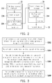
- FIG. 3 is a flowchart illustrating a method for bandwidth management of a backhaul network of a cell according to an embodiment of the disclosure.
- the method of the present embodiment is adapted to the aforementioned bandwidth management system 20. Detailed steps of the method of the present embodiment are described below with reference to various devices in the bandwidth management system 20 of FIG. 2 .
- the wireless resource manager 222 in the cell 22 establishes a bearer between the UE and the serving gateway or changes a previously established bearer (step S302). After the UE establishes the connection, the wireless resource manager 222 establishes a tunnel between the cell 22 and the serving gateway, and sets a TEID. Meanwhile, the wireless resource manager 222 sets a QCI of the bearer according to a service requirement of the UE.
- the label manager 224 assigns a packet label to the bearer, and sets the packet label on the data packets received from the UE (step S304).
- the label manager 224 for example, uses a virtual IP address as the packet label of the data packets, or sets a source port of the data packets to a specific value to serve as the packet label, or uses any other labelling method for labelling the data packets for identification, which is not limited by the embodiment.
- the label manager 224 sets a source port of the GTP-U packets to a specific value, for example, 1001 or other value according to the TEID, which is not limited by the disclosure.
- the label manager 224 may configure the virtual IP address by adopting a centralized or distributed configuration method.
- the controller 22 may configure an IP address section to the cell 22 according to the number of the cells and the traffic in the backhaul network, and the label manager 224 of the cell 22 allocates a virtual IP address in the IP address section to serve as the packet label of the bearer.
- the label manager 224 of the cell 22 may directly calculate the aforementioned IP address section according to its own IP address, and allocates a virtual IP address in the IP address section to serve as the packet label of the bearer.
- the bearer information notifier 226 transmits the packet label and the bandwidth management information of the bearer to the controller 24 of the backhaul network (step S306) for the routing path manager 244 of the controller 24 to arrange the routing path of the data packets using the packet label in the backhaul network according to the bandwidth management information in the bearer information manager 242 (step S308), where the bandwidth management information includes a TEID, a QCI of the bearer and a bandwidth requirement, for example, a downlink (DL) bandwidth and an uplink (UL) bandwidth of the MBR, and a DL bandwidth and an UL bandwidth of the GBR.
- the bandwidth management information includes a TEID, a QCI of the bearer and a bandwidth requirement, for example, a downlink (DL) bandwidth and an uplink (UL) bandwidth of the MBR, and a DL bandwidth and an UL bandwidth of the GBR.
- the routing path manager 24 executes a dynamic bandwidth management to the backhaul network to determine the routing path according to the QCI and the bandwidth requirement in the bandwidth management information.
- the routing path passes through at least one network device 26 in the backhaul network.
- the routing path manager 244 connects the network devices 26 on the routing path, and sets a flow table on the network devices 26, such that when each of the network devices 26 receives the data packets using the aforementioned packet label, the network device 26 automatically transmits the data packets to a next network device recorded in the flow table.
- the controller 24 may opportunely perform routing adjustment to the data packets sent to the backhaul network without performing complicated traffic identification, and the network devices 26 in the backhaul network are unnecessary to support seeing through the GPRS tunnel. Therefore, the method of the present embodiment may effectively reduce a construction cost of the backhaul network.
- the routing path manager 244 decides the routing path, the routing path manager 244, for example, further sets a last network device 26 (i.e. the last network device before reaching the serving gateway) on the routing path, such that when the network device 26 receives the data packets using the aforementioned packet label, the network device 26 modifies the packet label of the data packets to a standard value.
- a last network device 26 i.e. the last network device before reaching the serving gateway
- FIG. 4 is a flowchart illustrating a method for processing and routing data packets according to an embodiment of the disclosure.
- the method of the present embodiment is adapted to the aforementioned bandwidth management system 20. Detailed steps of the method of the present embodiment are described below with reference to various devices in the bandwidth management system 20 of FIG. 2 .
- the UE transmits the data packets to the small cell 22 (step S402), and the small cell 22 encapsulates the data packets into the GTP-U packets and sets a source port of the GTP-U packets to a specific value according to the TEID of the bearer (step S404).
- the set GTP-U packets are then sent to the backhaul network by the small cell 22, and the network devices 26 in the backhaul network route the GTP-U packets according to a setting of the controller 24 (step S406).
- the network device 26 modifies the source port of the data packets to a standard value, and transmits the data packets to the serving gateway (step S408).
- the serving gateway does not know that the source port of the data packets has ever been modified, which represents that the method of the present embodiment can be implemented without modifying the serving gateway.
- FIG. 5 is an example for processing and routing data packets according to an embodiment of the disclosure.
- the small cell 54 first, when a UE 52 is connected to a small cell 54, the small cell 54 establishes a bearer between the UE 52 and a serving gateway 58.
- the small cell 54 provides the bandwidth management information obtained when the small cell 54 establishes the bearer to a controller 562 of a backhaul network 56.
- the bandwidth management information includes: a TEID (i.e. 156) of the tunnel established between the small cell 54 and the serving gateway 58, a QCI (i.e. 4), a DL bandwidth of the MBR (i.e.
- the small cell 54 further encapsulates the data packets transmitted by the UE 52 into the GTP-U packets, and sets the source port of the GTP-U packets to 1001 according to the TEID of the bearer.
- the controller 562 executes bandwidth management to the backhaul network 56 according to the aforementioned bandwidth management information, so as to decide the routing path of the GTP-U packets, and the finally decided routing path is the small cell 54 ⁇ a switch A ⁇ a switch B ⁇ a switch C ⁇ the serving gateway 58, as shown in FIG. 5 .
- the controller 562 sets a flow table (as shown in table 2 below) of the switches A, B, C according to the routing path.
- the switches A, B, C when the switches A, B, C discover that the source port of the data packets is 1001, the switches A, B, C transmit the data packets to the port of a next hop, and perform a bandwidth management action of "enqueue" before transmitting the data packets, so as to cope with a traffic limitation.
- the actions performed in the last switch C i.e. the next hot thereof is the serving gateway 58 serving as the endpoint
- the GTP-U packets may receive the dynamic bandwidth management of the controller 562 in the backhaul network 56 until the last switch C modifies the source port thereof to the standard value (2152), and when the GTP-U packets are finally sent to the serving gateway 58, the serving gateway 58 does not know that the source port of the GTP-U packets has ever been modified.
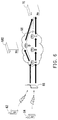
- FIG. 6 is an example for processing and routing data packets according to an embodiment of the disclosure.
- the small cell 66 first, when UEs 62, 64 are connected to a small cell 66, the small cell 66 respectively establishes bearers between the UEs 62, 64 and a serving gateway 70.
- the small cell 66 for example, provides the bandwidth management information obtained when the small cell 66 establishes the bearers to a controller 682 of a backhaul network 68.
- the small cell 66 encapsulates the data packets transmitted by the UE 62 into the GTP-U packets, and sets the source port of the GTP-U packets to 1001 according to the TEID of the bearer. Meanwhile, the small cell 66 encapsulates the data packets transmitted by the UE 64 into the GTP-U packets, and sets the source port of the GTP-U packets to 3003 according to the TEID of the bearer.
- the controller 682 executes bandwidth management to the backhaul network 68 according to the aforementioned bandwidth management information, so as to decide the routing path of the GTP-U packets, and the finally decided routing path of the GTP-U packets of the UE 62 is the small cell 66 ⁇ the switch A ⁇ the switch D ⁇ the serving gateway 70, and the routing path of the GTP-U packets of the UE 64 is the small cell 66 ⁇ the switch A ⁇ the switch B ⁇ the switch C ⁇ the serving gateway 70. Since the controller 682 determines that the traffic of the routing path (the switch ⁇ the switch B ⁇ the switch C) is excessively large, the GTP-U packets of the UE 62 are routed through another routing path (the switch A ⁇ the switch D ⁇ the serving gateway 70).
- the controller 682 sets a flow table (shown as a following table 4) of the switches A, B, C, D according to the routing paths.
- the GTP-U packets may receive the dynamic bandwidth management of the controller 682 in the backhaul network 68 until the last switches C, D in the routing path modify the source port thereof to the standard value (2152), and then the GTP-U packets are sent to the serving gateway 70.
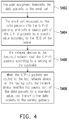
- FIG. 7 is a flowchart illustrating a method for processing and routing data packets according to an embodiment of the disclosure.
- the method of the present embodiment is adapted to the aforementioned bandwidth management system 20. Detailed steps of the method of the present embodiment are described below with reference to various devices of the bandwidth management system 20 of FIG. 2 .
- the UE transmits the data packets to the small cell 22 (step S702), and the small cell 22 encapsulates the data packets into the GTP-U packets, and sets a source IP address of the GTP-U packets to a virtual IP address according to the TEID of the bearer, and sets a destination IP address of the GTP-U packets to an IP address of the serving gateway (step S704).
- the set GTP-U packets are then sent to the backhaul network by the small cell 22, and the network devices 26 in the backhaul network route the GTP-U packets to the serving gateway according to a setting of the controller 24 (step S706).
- the small cell 22 after the small cell 22 decides the virtual IP address allocated to the bearer, the small cell 22, for example, reports a transport layer address of the GTP-U packets of the bearer to the serving gateway to serve as the aforementioned virtual IP address.
- the serving gateway may encapsulate the transmitted data packets into the GTP-U packets, and sets the source IP address of the GTP-U packets as the IP address of the serving gateway, and sets the destination IP address of the GTP-U packets as the virtual IP address.
- the set GTP-U packets are then sent to the backhaul network by the serving gateway, and the network devices 26 in the backhaul network route the GTP-U packets to the small cell 22 according to the setting of the controller 24.
- FIG. 8 and FIG. 9 are examples for processing and routing data packets according to an embodiment of the disclosure.
- the small cell 84 first, when a UE 82 is connected to a small cell 84, the small cell 84 establishes a bearer between the UE 82 and a serving gateway 88.
- the small cell 84 provides the bandwidth management information obtained when the small cell 84 establishes the bearer to a controller 862 of a backhaul network 86.
- the bandwidth management information includes: a TEID (i.e. 156) of the tunnel established between the small cell 84 and the serving gateway 88, a QCI (i.e. 4), a DL bandwidth of the MBR (i.e.
- the small cell 84 further encapsulates the data packets transmitted by the UE 82 into the GTP-U packets, and sets the source IP address of the GTP-U packets to a virtual IP address (i.e. 192.168.101.3) according to the TEID of the bearer.
- the controller 862 executes bandwidth management to the backhaul network 86 according to the aforementioned bandwidth management information, so as to decide the routing path of the GTP-U packets, and the finally decided routing path is the small cell 84 ⁇ the switch A ⁇ the switch B ⁇ the switch C ⁇ the serving gateway 88, as shown in FIG. 8 .
- the controller 862 sets a flow table (as shown in table 6 below) of the switches A, B, C according to the routing path.
- the switches A, B, C when the switches A, B, C discover that the source IP address of the GTP-U packets is the virtual IP address, the switches A, B, C transmit the GTP-U packets to the port of a next hop, and perform a bandwidth management action of "enqueue" before transmitting the GTP-U packets, so as to cope with a traffic limitation. Finally, the GTP-U packets are transmitted to the serving gateway 88.
- the serving gateway 88 may encapsulate the transmitted data packets into the GTP-U packets, and sets the source IP address of the GTP-U packets as the IP address of the serving gateway 88, and sets the destination IP address of the GTP-U packets as the virtual IP address.
- the controller 862 executes bandwidth management to the backhaul network 86 according to the aforementioned bandwidth management information, so as to decide the routing path of the GTP-U packets, and the finally decided routing path is the serving gateway 88 ⁇ the switch C ⁇ the switch B ⁇ the switch A ⁇ the small cell 84, as shown in FIG. 9 .
- the controller 862 sets a flow table (as shown in table 7 below) of the switches A, B, C according to the routing path.
- the switches A, B, C when the switches A, B, C discover that the destination IP address of the GTP-U packets is the virtual IP address, the switches A, B, C transmit the GTP-U packets to the port of a next hop, and perform the bandwidth management action of "enqueue" before transmitting the GTP-U packets, so as to cope with a traffic limitation. Finally, the GTP-U packets are transmitted to the small cell 84.
- the small cell labels the data packets, and assists the programmable network in identifying a data flow.
- the controller in the programmable network may identify a data flow without seeing through the packet content in the tunnel, and may implement dynamic bandwidth management, so as to reduce a construction cost of the backhaul network.
Landscapes
- Engineering & Computer Science (AREA)
- Computer Networks & Wireless Communication (AREA)
- Signal Processing (AREA)
- Quality & Reliability (AREA)
- Mobile Radio Communication Systems (AREA)
Abstract
Description
- The disclosure relates to a method and a system bandwidth management of a backhaul network of the cell.
- Along with continuous development of wireless apparatuses and application software thereof, users are more dependent on mobile networks to watch video files and process massive data, and a data transmission capacity of the network has grown exponentially in just a few years. In order to provide consumers with a broader bandwidth, a better network transmission quality, telecom operators have to constantly look for solutions to cope with bandwidth requirements of the users in the future. Since the cells built in a convention large cell network system is not many, a backhaul network is relatively simple, which generally adopts a dedicated line to transmit information back to a core network. Compared to a small cell network system constructed by small cells, a wireless access technique of the large cell network system is slow in impact on a network capacity growth, and acquirement of frequency band involves a wide level and is laborious and time-consuming. Accordingly, the small cells are going to be built in large quantities in the future, and investment of industry funds and setting of subsequent supporting standards are all developed towards the trend of the small cell network system.
- In order to provide a service quality assurance service in a telecommunication network, a 3rd generation partnership project (3GPP) provides a novel quality of service (QoS) concept. In a long term evolution (LTE) radio network, traffic is adopted to differentiate, and multiple bearers are adopted in architecture, so as to determine a transmission sequence of each bearer according to different QoS class identifiers (QCI). Under the LTE environment, the establishment of bearers is controlled by telecom operators, for example, a mobility management entity (MME), and during the process of establishing the bearers, the MME gives the corresponding QCI value to each bearer, and the QCI value has the corresponding QoS. The QoS represents a transmission quality assurance of the bearers of an evolved packet system (EPS), and through the QCI mechanism, each of the bearers is assured to reach a bearer service quality required by a control plane, and is complied with a transfer delay of a user bearer.
- A differentiated services code point (DSCP) is a bandwidth management mechanism of the current backhaul network, where the bandwidth management of a wireless terminal adopts the QCI mechanism, and when data is to be transmitted to the backhaul network, the cell encapsulates the data into general packet radio service (GPRS) tunnelling protocol-user (GTP-U) packets, and labels a DSCP code on a packet header of an outer layer to serve as an identification of a data flow.
- However, when a plenty of small cells are constructed in the future, the backhaul network is no longer simple, and a network load is varied along with user's movement and is varied along with time and user's bandwidth requirement. The patterns and emerging positions of the data flow at daytime and the data flow at night time are all different. Since variation of the backhaul network is large, management complexity thereof is greatly increased, and since dynamic and real-time adjustment of the backhaul network is required, it is hard to perform a proper bandwidth management to achieve the QoS standard specified by the 3GPP.
- In case that the backhaul network becomes more and more complicated, the current bandwidth management mechanism is hard to satisfy the demand of the 3GPP standard, and switches/routers on the backhaul network do not necessarily support the DSCP technique. Since the DSCP cannot support a maximum bit rate (MBR)/guaranteed bit rate (GBR), the current bandwidth management mechanism cannot provide a suitable bandwidth management function in response to the network load with large variability.
- On the other hand, since the backhaul network does not involve in information exchange between the small cell and the core network, the backhaul network cannot get to learn bandwidth management information and setting established between the cell and a serving gateway (S-GW). If the bandwidth management is required, the backhaul network is required to analyse user packets encapsulated through the GPRS tunnelling protocol. In other words, the switches/routers are required to see through the GPRS tunnel in order to process different bearers according to information obtained after analysis. If the switches are required to have the packet analysis function, the cost thereof must be high.
- The disclosure is directed to a cell and a method and a system for bandwidth management of a backhaul network of the cell, which improve a bandwidth management capability and adaptability of the backhaul network of the small cell.
- An embodiment in accordance with the disclosure provides a method for bandwidth management of a backhaul network of a cell, which is adapted for arranging a routing path of a bearer established between a user equipment and a serving gateway by the cell in the backhaul network. In the method, the cell connects the user equipment to establish the bearer between the user equipment and the serving gateway or change the established bearer. The cell sets a packet label on data packets of the bearer and transmits the packet label and bandwidth management information of the bearer to a controller of the backhaul network for the controller to arrange the routing path of the data packets using the packet label in the backhaul network according to the bandwidth management information, where the bandwidth management information includes a tunnel endpoint identifier (TEID), a quality of service (QoS) class identifier (QCI) of the bearer and a bandwidth requirement.
- An embodiment in accordance with the disclosure provides a bandwidth management system of a backhaul network of a cell, which includes at least one cell, a plurality of network devices and a controller of the backhaul network. Each of the cells includes a wireless resource manager, a label manager and a bearer information notifier, where the wireless resource manager is configured to establish a bearer between a user equipment and a serving gateway. The label manager is configured to set a packet label on data packets of the bearer. The bearer information notifier is configured to obtain bandwidth management information of the bearer and transmit the packet label and the bandwidth management information of the bearer to the controller of the backhaul network, where the bandwidth management information includes a tunnel endpoint identifier (TEID), a quality of service (QoS) class identifier (QCI) of the bearer and a bandwidth requirement. The controller connects each of the cells, and includes a bearer information manager and a routing path manager, where the bearer information manager is configured to receive and manage the bandwidth management information transmitted by each of the cells, and the routing path manager arranges the routing path of the data packets using the packet label in the backhaul network according to the bandwidth management information of each of the cells.
- An embodiment in accordance with the disclosure provides a cell including a wireless resource manager, a label manager and a bearer information notifier, where the wireless resource manager is configured to establish a bearer between a user equipment and a serving gateway. The label manager is configured to set a packet label on data packets of the bearer. The bearer information notifier is configured to obtain bandwidth management information of the bearer and transmit the packet label and the bandwidth management information of the bearer to a controller of a backhaul network, such that the controller accordingly arranges a routing path of the data packets using the packet label in a plurality of network devices in the backhaul network. The bandwidth management information includes a tunnel endpoint identifier (TEID), a quality of service (QoS) class identifier (QCI) of the bearer and a bandwidth requirement.
- According to the above descriptions, in the cell and the method and the system for bandwidth management of the backhaul network of the cell of the disclosure, the small cell may assist the controller in the programmable network to identify a data flow without seeing through the packet content in the tunnel, and may implement functions such as dynamic bandwidth management.
- In order to make the aforementioned and other features and advantages of the disclosure comprehensible, several exemplary embodiments accompanied with figures are described in detail below.
- The accompanying drawings are included to provide a further understanding of the disclosure, and are incorporated in and constitute a part of this specification. The drawings illustrate embodiments of the disclosure and, together with the description, serve to explain the principles of the disclosure.
-
FIG. 1 is a schematic diagram of bandwidth management of a backhaul network of a cell according to an embodiment of the disclosure. -
FIG. 2 is a block diagram of a bandwidth management system of a backhaul network of a cell according to an embodiment of the disclosure. -
FIG. 3 is a flowchart illustrating a method for bandwidth management of a backhaul network of a cell according to an embodiment of the disclosure. -
FIG. 4 is a flowchart illustrating a method for processing and routing data packets according to an embodiment of the disclosure. -
FIG. 5 is an example for processing and routing data packets according to an embodiment of the disclosure. -
FIG. 6 is an example for processing and routing data packets according to an embodiment of the disclosure. -
FIG. 7 is a flowchart illustrating a method for processing and routing data packets according to an embodiment of the disclosure. -
FIG. 8 is an example for processing and routing data packets according to an embodiment of the disclosure. -
FIG. 9 is an example for processing and routing data packets according to an embodiment of the disclosure. - In the disclosure, during an initial process when a small cell establishes a bearer for a user equipment (UE), the small cell sets a packet label for the bearer, and provides the packet label and information such as a QoS class identifier (QCI) of the bearer, a maximum bit rate (MBR), or a guaranteed bit rate (GBR), to a controller in a backhaul network, and the controller may set a routing behaviour of switches/routers in the backhaul network. In this way, when the small cell transmits data packets of the UE to the backhaul network, the switches/routers may learn a traffic characteristic of the data packets so as to perform corresponding processing as long as the switches/routers identify the packet label on the data packets.
- In detail,
FIG. 1 is a schematic diagram of bandwidth management of a backhaul network of a cell according to an embodiment of the disclosure. Referring toFIG. 1 , first, asmall cell 12 supporting a long term evolution-advanced (LTE-A) technique establishes a bearer between a UE 14 and aserving gateway 16 thereof, and designs a packet label for such bearer. Then, thesmall cell 12 transmits the packet label and the MBR/GBR information and all of the QoS information of the bearer to acontroller 182 in thebackhaul network 18. Thecontroller 182 then sets a routing behaviour of each of network devices (for example, switches or routers, and in the present embodiment, switches A-D are taken as an example for description) in thebackhaul network 18 according to the information. In theprogrammable backhaul network 18, thecontroller 182 has all of the QoS information of the bearer, such that thecontroller 182 may identify the traffic without seeing through the tunnel, so as to perform dynamic traffic management on the data packets of the bearer. A range that the data packets receive the dynamic traffic management, for example, starts from an action that thesmall cell 12 sets the packet label till an action that a last switch (for example, the switches A, D) in front of theserving gateway 16 removes the packet label. - The aforementioned switches are, for example, tier 2 network switches of a tier 2 data link layer defined by an open system interconnection reference model (OSI model), which have functions of virtual local area network (VLAN) division, port auto-negotiation, MAC access control list, etc.; or tier 3 network switches supporting a tier 3 network layer protocol, which support a certain router function for connecting different network segments, and can establish a direct connection between two network segments by inquiring and learning from a default serving gateway; or tier 4 network switches supporting a tier 4 transmission layer protocol, which may connect a session with a concrete Internet protocol (IP) address to practise a virtual IP. Moreover, the aforementioned routers may support the tier 3 network layer defined by the OSI model or the protocol above the tier 3, which not only has the functions of the switch, but may also has a function of selecting an optimal path from a plurality of paths while taking the flow table as a basis for packet transmission.
-
FIG. 2 is a block diagram of a bandwidth management system of a backhaul network of a cell according to an embodiment of the disclosure. Referring toFIG. 2 , the bandwidth management system 20 of the backhaul network of the present embodiment adopts a programmable network, for example, a software-defined network (SDN), and includes at least one cell (in the present embodiment, asmall cell 22 is taken as an example for description), acontroller 24 and a plurality ofnetwork devices 26. Data transmission between thesmall cell 22 and thecontroller 24 and between thecontroller 24 and thenetwork devices 26 is implemented through a wired or wireless network connection. - The
small cell 22 is, for example, a low-power radio accessing equipment operated by a telecom operator under a licensed spectrum, and based on emission powers from small to large, the types of thesmall cell 22 may include a femtocell, a picocell and a microcell. Thesmall cell 22 includes awireless resource manager 222, alabel manager 224 and abearer information notifier 226, where thewireless resource manager 222 supports a radio resource management (RRM), and is configured to connect a UE (not shown) and establish a bearer between the UE and a serving gateway (not shown). Thelabel manager 224 is in charge of managing a connection relationship between the bearer and a packet label, and is configured to set the packet label on data packets of the bearer established by thewireless resource manager 222 for thenetwork device 26 in the backhaul network to identify the data packets. Thelabel manager 224 can be independently configured or configured in thewireless resource manager 222, which is not limited by the present embodiment. Thebearer information notifier 226 is configured to obtain bandwidth management information of the bearer and create a notification message for notifying thecontroller 24 in the backhaul network, where the bandwidth management information includes a tunnel endpoint identifier (TEID), a quality of service (QoS) class identifier (QCI) of the bearer and a bandwidth requirement such as MBR or GBR, and thecontroller 24 may manage the bandwidth of the backhaul network according to the bandwidth management information. - The
controller 24 is, for example, a controller in charge of managing thenetwork devices 26 in the programmable network. Thecontroller 24 is implemented by software, plans the network in a central controlling manner, and sends commands to thenetwork devices 26 for controlling a network traffic. Thecontroller 24 includes abearer information manager 242 and arouting path manager 244, where thebearer information manager 242 is configured to receive the bandwidth management information from thebearer information notifier 226 of thesmall cell 22, and manages the bandwidth management information of all of the cells. Therouting path manager 224 arranges the routing path of the data packets using the aforementioned packet label in the backhaul network according to the bandwidth management information of each of the cells. It should be noted that thebearer information manager 242 is, for example, implemented by an application program installed in thecontroller 24, and works in coordination with therouting path manager 224 originally configured in thecontroller 24 to implement a method for bandwidth management of the embodiment of the disclosure. - In detail,
FIG. 3 is a flowchart illustrating a method for bandwidth management of a backhaul network of a cell according to an embodiment of the disclosure. Referring toFIG. 2 and FIG. 3 , the method of the present embodiment is adapted to the aforementioned bandwidth management system 20. Detailed steps of the method of the present embodiment are described below with reference to various devices in the bandwidth management system 20 ofFIG. 2 . - First, when the UE is connected to the
cell 22, thewireless resource manager 222 in thecell 22 establishes a bearer between the UE and the serving gateway or changes a previously established bearer (step S302). After the UE establishes the connection, thewireless resource manager 222 establishes a tunnel between thecell 22 and the serving gateway, and sets a TEID. Meanwhile, thewireless resource manager 222 sets a QCI of the bearer according to a service requirement of the UE. - Then, the
label manager 224 assigns a packet label to the bearer, and sets the packet label on the data packets received from the UE (step S304). Thelabel manager 224, for example, uses a virtual IP address as the packet label of the data packets, or sets a source port of the data packets to a specific value to serve as the packet label, or uses any other labelling method for labelling the data packets for identification, which is not limited by the embodiment. - In the embodiment of setting the source port, after the
wireless resource manager 222 encapsulates the data packets of the bearer as GPRS tunnelling protocol-user (GTP-U) packets, thelabel manager 224, for example, sets a source port of the GTP-U packets to a specific value, for example, 1001 or other value according to the TEID, which is not limited by the disclosure. - On the other hand, in the embodiment of using the virtual IP address, the
label manager 224 may configure the virtual IP address by adopting a centralized or distributed configuration method. In the centralized configuration method, thecontroller 22 may configure an IP address section to thecell 22 according to the number of the cells and the traffic in the backhaul network, and thelabel manager 224 of thecell 22 allocates a virtual IP address in the IP address section to serve as the packet label of the bearer. Moreover, in the distributed configuration method, thelabel manager 224 of thecell 22 may directly calculate the aforementioned IP address section according to its own IP address, and allocates a virtual IP address in the IP address section to serve as the packet label of the bearer. - Then, the
bearer information notifier 226 transmits the packet label and the bandwidth management information of the bearer to thecontroller 24 of the backhaul network (step S306) for therouting path manager 244 of thecontroller 24 to arrange the routing path of the data packets using the packet label in the backhaul network according to the bandwidth management information in the bearer information manager 242 (step S308), where the bandwidth management information includes a TEID, a QCI of the bearer and a bandwidth requirement, for example, a downlink (DL) bandwidth and an uplink (UL) bandwidth of the MBR, and a DL bandwidth and an UL bandwidth of the GBR. - The
routing path manager 244, for example, executes a dynamic bandwidth management to the backhaul network to determine the routing path according to the QCI and the bandwidth requirement in the bandwidth management information. The routing path passes through at least onenetwork device 26 in the backhaul network. - After the routing path is determined, the
routing path manager 244 connects thenetwork devices 26 on the routing path, and sets a flow table on thenetwork devices 26, such that when each of thenetwork devices 26 receives the data packets using the aforementioned packet label, thenetwork device 26 automatically transmits the data packets to a next network device recorded in the flow table. - Therefore, by using the
small cell 22 to actively provide thecontroller 24 with the information required for executing the bandwidth management, thecontroller 24 may opportunely perform routing adjustment to the data packets sent to the backhaul network without performing complicated traffic identification, and thenetwork devices 26 in the backhaul network are unnecessary to support seeing through the GPRS tunnel. Therefore, the method of the present embodiment may effectively reduce a construction cost of the backhaul network. - It should be noted that after the
routing path manager 244 decides the routing path, therouting path manager 244, for example, further sets a last network device 26 (i.e. the last network device before reaching the serving gateway) on the routing path, such that when thenetwork device 26 receives the data packets using the aforementioned packet label, thenetwork device 26 modifies the packet label of the data packets to a standard value. - In detail,
FIG. 4 is a flowchart illustrating a method for processing and routing data packets according to an embodiment of the disclosure. Referring toFIG. 2 andFIG. 4 , the method of the present embodiment is adapted to the aforementioned bandwidth management system 20. Detailed steps of the method of the present embodiment are described below with reference to various devices in the bandwidth management system 20 ofFIG. 2 . - First, the UE transmits the data packets to the small cell 22 (step S402), and the
small cell 22 encapsulates the data packets into the GTP-U packets and sets a source port of the GTP-U packets to a specific value according to the TEID of the bearer (step S404). - The set GTP-U packets are then sent to the backhaul network by the
small cell 22, and thenetwork devices 26 in the backhaul network route the GTP-U packets according to a setting of the controller 24 (step S406). - When the GTP-U packets are routed to the last network device 26 (i.e. the last network device before reaching the serving gateway) on the routing path, the
network device 26 modifies the source port of the data packets to a standard value, and transmits the data packets to the serving gateway (step S408). In this way, when the data packets are sent to the serving gateway, the serving gateway does not know that the source port of the data packets has ever been modified, which represents that the method of the present embodiment can be implemented without modifying the serving gateway. - For example,
FIG. 5 is an example for processing and routing data packets according to an embodiment of the disclosure. Referring toFIG. 5 , first, when aUE 52 is connected to asmall cell 54, thesmall cell 54 establishes a bearer between theUE 52 and a servinggateway 58. Thesmall cell 54, for example, provides the bandwidth management information obtained when thesmall cell 54 establishes the bearer to acontroller 562 of abackhaul network 56. As shown in a following table 1, the bandwidth management information includes: a TEID (i.e. 156) of the tunnel established between thesmall cell 54 and the servinggateway 58, a QCI (i.e. 4), a DL bandwidth of the MBR (i.e. 20 Mbps), an UL bandwidth of the MBR (i.e. 2 Mbps), and a DL bandwidth of the GBR (i.e. 2 Mbps), and an UL bandwidth of the GBR (i.e. 1 Mbps). Moreover, thesmall cell 54 further encapsulates the data packets transmitted by theUE 52 into the GTP-U packets, and sets the source port of the GTP-U packets to 1001 according to the TEID of the bearer.Table 1 TEID QCI MBR DL MBR UL GBR DL GBR UL Source port 156 4 20Mbps 2 Mbps 2 Mbps 1 Mbps 1001 - The
controller 562 executes bandwidth management to thebackhaul network 56 according to the aforementioned bandwidth management information, so as to decide the routing path of the GTP-U packets, and the finally decided routing path is thesmall cell 54→a switch A→a switch B→a switch C→the servinggateway 58, as shown inFIG. 5 . Thecontroller 562 sets a flow table (as shown in table 2 below) of the switches A, B, C according to the routing path.Table 2 Switch Source IP address Source port Action A 140.96.101.100 1001 Enqueue = port_to_B:queue01 B 140.96.101.100 1001 Enqueue = port_to_C:queue01 C 140.96.101.100 1001 Modify the source port=2152 Output = to port_to_S-GW - According to the above setting, when the switches A, B, C discover that the source port of the data packets is 1001, the switches A, B, C transmit the data packets to the port of a next hop, and perform a bandwidth management action of "enqueue" before transmitting the data packets, so as to cope with a traffic limitation. Particularly, the actions performed in the last switch C (i.e. the next hot thereof is the serving
gateway 58 serving as the endpoint) include: modify the source port of the GTP-U packets to the original standard port number 2152, and transmit the GTP-U packets to the servinggateway 58. - It should be noted that after the source port of the GTP-U packets is changed to the specific value (1001) at the
small cell 54, the GTP-U packets may receive the dynamic bandwidth management of thecontroller 562 in thebackhaul network 56 until the last switch C modifies the source port thereof to the standard value (2152), and when the GTP-U packets are finally sent to the servinggateway 58, the servinggateway 58 does not know that the source port of the GTP-U packets has ever been modified. - In the case that two UEs are connected,
FIG. 6 is an example for processing and routing data packets according to an embodiment of the disclosure. Referring toFIG. 6 , first, whenUEs small cell 66, thesmall cell 66 respectively establishes bearers between theUEs gateway 70. Thesmall cell 66, for example, provides the bandwidth management information obtained when thesmall cell 66 establishes the bearers to acontroller 682 of abackhaul network 68. As shown in a following table 3, thesmall cell 66 encapsulates the data packets transmitted by theUE 62 into the GTP-U packets, and sets the source port of the GTP-U packets to 1001 according to the TEID of the bearer. Meanwhile, thesmall cell 66 encapsulates the data packets transmitted by theUE 64 into the GTP-U packets, and sets the source port of the GTP-U packets to 3003 according to the TEID of the bearer.Table 3 TEID QCI MBR DL MBR UL GBR DL GBR UL Source port 156 4 9Mbps 2 Mbps 2 Mbps 1 Mbps 1001 133 3 2Mbps 2 Mbps 1 Mbps 1 Mbps 3003 - The
controller 682 executes bandwidth management to thebackhaul network 68 according to the aforementioned bandwidth management information, so as to decide the routing path of the GTP-U packets, and the finally decided routing path of the GTP-U packets of theUE 62 is thesmall cell 66→the switch A→the switch D→the servinggateway 70, and the routing path of the GTP-U packets of theUE 64 is thesmall cell 66→the switch A→the switch B→the switch C→the servinggateway 70. Since thecontroller 682 determines that the traffic of the routing path (the switch→the switch B→the switch C) is excessively large, the GTP-U packets of theUE 62 are routed through another routing path (the switch A→the switch D→the serving gateway 70). Finally, thecontroller 682 sets a flow table (shown as a following table 4) of the switches A, B, C, D according to the routing paths.Table 4 Switch Source network address Source port Action A 140.96.101.100 1001 Enqueue = port_to_B:queue01 140.96.101.100 3003 Enqueue = port_to_D:queue01 B 140.96.101.100 1001 Enqueue = port_to_C:queue01 C 140.96.101.100 1001 Modify source port=2152 Output = to port_to_S-GW D 140.96.101.100 3003 Modify source port=2152 Output = to port_to_S-GW - Similar to the aforementioned embodiment, after the source port of the GTP-U packets of the
UEs small cell 66, the GTP-U packets may receive the dynamic bandwidth management of thecontroller 682 in thebackhaul network 68 until the last switches C, D in the routing path modify the source port thereof to the standard value (2152), and then the GTP-U packets are sent to the servinggateway 70. - On the other hand, in case that the virtual IP address is used to serve as the packet label,
FIG. 7 is a flowchart illustrating a method for processing and routing data packets according to an embodiment of the disclosure. Referring toFIG. 2 andFIG. 7 , the method of the present embodiment is adapted to the aforementioned bandwidth management system 20. Detailed steps of the method of the present embodiment are described below with reference to various devices of the bandwidth management system 20 ofFIG. 2 . - First, the UE transmits the data packets to the small cell 22 (step S702), and the
small cell 22 encapsulates the data packets into the GTP-U packets, and sets a source IP address of the GTP-U packets to a virtual IP address according to the TEID of the bearer, and sets a destination IP address of the GTP-U packets to an IP address of the serving gateway (step S704). The set GTP-U packets are then sent to the backhaul network by thesmall cell 22, and thenetwork devices 26 in the backhaul network route the GTP-U packets to the serving gateway according to a setting of the controller 24 (step S706). - It should be noted that after the
small cell 22 decides the virtual IP address allocated to the bearer, thesmall cell 22, for example, reports a transport layer address of the GTP-U packets of the bearer to the serving gateway to serve as the aforementioned virtual IP address. In this way, when the serving gateway wants to transmit data back to thesmall cell 22, the serving gateway may encapsulate the transmitted data packets into the GTP-U packets, and sets the source IP address of the GTP-U packets as the IP address of the serving gateway, and sets the destination IP address of the GTP-U packets as the virtual IP address. The set GTP-U packets are then sent to the backhaul network by the serving gateway, and thenetwork devices 26 in the backhaul network route the GTP-U packets to thesmall cell 22 according to the setting of thecontroller 24. - For example,
FIG. 8 andFIG. 9 are examples for processing and routing data packets according to an embodiment of the disclosure. Referring toFIG. 8 , first, when aUE 82 is connected to asmall cell 84, thesmall cell 84 establishes a bearer between theUE 82 and a servinggateway 88. Thesmall cell 84, for example, provides the bandwidth management information obtained when thesmall cell 84 establishes the bearer to acontroller 862 of abackhaul network 86. As shown in a following table 5, the bandwidth management information includes: a TEID (i.e. 156) of the tunnel established between thesmall cell 84 and the servinggateway 88, a QCI (i.e. 4), a DL bandwidth of the MBR (i.e. 20 Mbps), an UL bandwidth of the MBR (i.e. 2 Mbps), and a DL bandwidth of the GBR (i.e. 2 Mbps), and an UL bandwidth of the GBR (i.e. 1 Mbps). Moreover, thesmall cell 84 further encapsulates the data packets transmitted by theUE 82 into the GTP-U packets, and sets the source IP address of the GTP-U packets to a virtual IP address (i.e. 192.168.101.3) according to the TEID of the bearer.Table 5 TEID QCI MBR DL MBR UL GBR DL GBR UL Virtual IP 156 4 20Mbps 2 Mbps 2 Mbps 1 Mbps 192.168.101.3 - The
controller 862 executes bandwidth management to thebackhaul network 86 according to the aforementioned bandwidth management information, so as to decide the routing path of the GTP-U packets, and the finally decided routing path is thesmall cell 84→the switch A→the switch B→the switch C→the servinggateway 88, as shown inFIG. 8 . Thecontroller 862 sets a flow table (as shown in table 6 below) of the switches A, B, C according to the routing path.Table 6 Switch Source IP address Action A 140.96.101.100 Enqueue = port_to_B:queue01 B 140.96.101.100 Enqueue = port_to_C:queue01 C 140.96.101.100 Enqueue = port_to_S-GW:queue01 - According to the above setting, when the switches A, B, C discover that the source IP address of the GTP-U packets is the virtual IP address, the switches A, B, C transmit the GTP-U packets to the port of a next hop, and perform a bandwidth management action of "enqueue" before transmitting the GTP-U packets, so as to cope with a traffic limitation. Finally, the GTP-U packets are transmitted to the serving
gateway 88. - On the other hand, when the serving
gateway 88 wants to transmit dada back to thesmall cell 84, the servinggateway 88 may encapsulate the transmitted data packets into the GTP-U packets, and sets the source IP address of the GTP-U packets as the IP address of the servinggateway 88, and sets the destination IP address of the GTP-U packets as the virtual IP address. Thecontroller 862 executes bandwidth management to thebackhaul network 86 according to the aforementioned bandwidth management information, so as to decide the routing path of the GTP-U packets, and the finally decided routing path is the servinggateway 88→the switch C→the switch B→the switch A→thesmall cell 84, as shown inFIG. 9 . Thecontroller 862 sets a flow table (as shown in table 7 below) of the switches A, B, C according to the routing path.Table 7 Switch Destination IP address Action A 140.96.101.100 Enqueue = port_to_SC:queue01 B 140.96.101.100 Enqueue = port_to_A:queue01 C 140.96.101.100 Enqueue = port_to_B:queue01 - According to the above setting, when the switches A, B, C discover that the destination IP address of the GTP-U packets is the virtual IP address, the switches A, B, C transmit the GTP-U packets to the port of a next hop, and perform the bandwidth management action of "enqueue" before transmitting the GTP-U packets, so as to cope with a traffic limitation. Finally, the GTP-U packets are transmitted to the
small cell 84. - In summary, in the cell and the method and the system for bandwidth management of the backhaul network of the cell of the disclosure, the small cell labels the data packets, and assists the programmable network in identifying a data flow. In this way, the controller in the programmable network may identify a data flow without seeing through the packet content in the tunnel, and may implement dynamic bandwidth management, so as to reduce a construction cost of the backhaul network.
Claims (20)
- A method for bandwidth management of a backhaul network (18, 56, 68, 86) of a cell (12, 22, 54, 66, 84), adapted for arranging a routing path of a bearer established between a user equipment (14, 52, 62, 64, 82) and a serving gateway (16, 58, 70, 88) by the cell (12, 22, 54, 66, 84) in the backhaul network (18, 56, 68, 86), the method comprising:connecting (S302) the user equipment (14, 52, 62, 64, 82) by the cell (12, 22, 54, 66, 84) to establish the bearer between the user equipment (14, 52, 62, 64, 82) and the serving gateway (16, 58, 70, 88) or change the established bearer;setting (S304) a packet label on data packets of the bearer by the cell (12, 22, 54, 66, 84); andtransmitting (S306) the packet label and bandwidth management information of the bearer to a controller (182, 24, 562, 682, 862) of the backhaul network (18, 56, 68, 86) by the cell (12, 22, 54, 66, 84) for the controller (182, 24, 562, 682, 862) to arrange (S308) the routing path of the data packets using the packet label in the backhaul network (18, 56, 68, 86) according to the bandwidth management information, wherein the bandwidth management information comprises a tunnel endpoint identifier (TEID), a quality of service (QoS) class identifier (QCI) of the bearer and a bandwidth requirement.
- The method for bandwidth management of the backhaul network (18, 56, 68, 86) of the cell (12, 22, 54, 66, 84) as claimed in claim 1, wherein in the step of setting the packet label on the data packets of the bearer by the cell (12, 22, 54, 66, 84), the method further comprises:receiving an Internet protocol (IP) address section configured by the controller (182, 24, 562, 682, 862) by the cell (12, 22, 54, 66, 84); andallocating a virtual IP address in the IP address section by the cell (12, 22, 54, 66, 84) to serve as the packet label of the bearer.
- The method for bandwidth management of the backhaul network (18, 56, 68, 86) of the cell (12, 22, 54, 66, 84) as claimed in claim 1, wherein in the step of setting the packet label on the data packets of the bearer by the cell (12, 22, 54, 66, 84), the method further comprises:calculating an IP address section by the cell (12, 22, 54, 66, 84) according to an IP address of the cell (12, 22, 54, 66, 84) itself; andallocating a virtual IP address in the IP address section by the cell (12, 22, 54, 66, 84) to serve as the packet label of the bearer.
- The method for bandwidth management of the backhaul network (18, 56, 68, 86) of the cell (12, 22, 54, 66, 84) as claimed in any one of claims 1 to 3, wherein the step of setting the packet label on the data packets of the bearer by the cell (12, 22, 54, 66, 84) comprises:encapsulating (S404) the data packets of the bearer into general packet radio service (GPRS) tunnelling protocol-user (GTP-U) packets by the cell (12, 22, 54, 66, 84), and setting a source port of the GTP-U packets according to the TEID.
- The method for bandwidth management of the backhaul network (18, 56, 68, 86) of the cell (12, 22, 54, 66, 84) as claimed in any one of claims 1 to 4, wherein the step of arranging the routing path of the data packets using the packet label in the backhaul network (18, 56, 68, 86) by the controller (182, 24, 562, 682, 862) according to the bandwidth management information comprises:executing dynamic bandwidth management to the backhaul network (18, 56, 68, 86) by the controller (182, 24, 562, 682, 862) to decide the routing path according to the QCI and the bandwidth requirement in the bandwidth management information, wherein the routing path passes through a plurality of network devices (26, A, B, C, D); andsetting a flow table of each of the network devices (26, A, B, C, D) on the routing path by the controller (182, 24, 562, 682, 862) to enable each of the plurality of network devices (26, A, B, C, D) to transmit the data packets to a next network device (26, A, B, C, D) recorded in the flow table when receiving the data packets using the packet label.
- The method for bandwidth management of the backhaul network (18, 56, 68, 86) of the cell (12, 22, 54, 66, 84) as claimed in claim 5, wherein the step of arranging the routing path of the data packets using the packet label in the backhaul network (18, 56, 68, 86) by the controller (182, 24, 562, 682, 862) according to the bandwidth management information further comprises:setting a last network device (26, A, B, C, D) on the routing path before reaching the serving gateway (16, 58, 70, 88) to enable the last network device (26, A, B, C, D) to modify the packet label of the data packets to an standard value when receiving the data packets using the packet label.
- The method for bandwidth management of the backhaul network (18, 56, 68, 86) of the cell (12, 22, 54, 66, 84) as claimed in claim 5, wherein the plurality of network devices (26, A, B, C, D) support tier 2 switches or switches above tier 2 defined by an open system interconnection reference model (OSI model), or supports tier 3 routers or routers above tier 3 defined by the OSI model.
- A bandwidth management system (20) of a backhaul network (18, 56, 68, 86) of a cell (12, 22, 54, 66, 84), comprising:at least one cell (12, 22, 54, 66, 84), each cell (12, 22, 54, 66, 84) comprising:a wireless resource manager (222) being configured to establish a bearer between a user equipment (14, 52, 62, 64, 82) and a serving gateway (16, 58, 70, 88);a label manager (224) being configured to set a packet label on data packets of the bearer; anda bearer information notifier (226) being configured to obtain bandwidth management information of the bearer, and transmit the packet label and the bandwidth management information of the bearer to a controller (182, 24, 562, 682, 862) of the backhaul network (18, 56, 68, 86), wherein the bandwidth management information comprises a TEID, a QCI of the bearer and a bandwidth requirement;a plurality of network devices (26, A, B, C, D); anda controller (182, 24, 562, 682, 862) being configured to connect each of the cells (12, 22, 54, 66, 84) and each of the plurality of network devices (26, A, B, C, D), and comprising:a bearer information manager (242) being configured to receive and manage the bandwidth management information transmitted by each of the cell (12, 22, 54, 66, 84)s; anda routing path manager (244) being configured to arrange a routing path of the data packets using the packet label in the backhaul network (18, 56, 68, 86) according to the bandwidth management information of each of the cell (12, 22, 54, 66, 84)s.
- The bandwidth management system (20) of the backhaul network (18, 56, 68, 86) of the cell (12, 22, 54, 66, 84) as claimed in claim 8, wherein the label manager further receives an IP address section configured by the controller (182, 24, 562, 682, 862), and allocates one virtual IP address in the IP address section to serve as the packet label of the bearer.
- The bandwidth management system (20) of the backhaul network (18, 56, 68, 86) of the cell (12, 22, 54, 66, 84) as claimed in claim 8, wherein the label manager further calculates an IP address section according to an IP address of the cell (12, 22, 54, 66, 84) itself, and allocates a virtual IP address in the IP address section to serve as the packet label of the bearer.
- The bandwidth management system (20) of the backhaul network (18, 56, 68, 86) of the cell (12, 22, 54, 66, 84) as claimed in any one of claims 8 to 10, wherein the label manager encapsulates the data packets of the bearer into GTP-U packets, and sets a source port of the GTP-U packets according to the TEID.
- The bandwidth management system (20) of the backhaul network (18, 56, 68, 86) of the cell (12, 22, 54, 66, 84) as claimed in any one of claims 8 to 11, wherein the routing path manager executes dynamic bandwidth management to the backhaul network (18, 56, 68, 86) to decide the routing path according to the QCI and the bandwidth requirement in the bandwidth management information, wherein the routing path passes through the plurality of network devices (26, A, B, C, D), and sets a flow table of each of the plurality of network devices (26, A, B, C, D) on the routing path to enable each of the plurality of network devices (26, A, B, C, D) to transmit the data packets to a next network device (26, A, B, C, D) recorded in the flow table when receiving the data packets using the packet label.
- The bandwidth management system (20) of the backhaul network (18, 56, 68, 86) of the cell (12, 22, 54, 66, 84) as claimed in claim 12, wherein the routing path manager further sets a last network device (26, A, B, C, D) on the routing path before reaching the serving gateway (16, 58, 70, 88) to enable the last network device (26, A, B, C, D) to modify the packet label of the data packets to a standard value when receiving the data packets using the packet label.
- The bandwidth management system (20) of the backhaul network (18, 56, 68, 86) of the cell (12, 22, 54, 66, 84) as claimed in claim 12, wherein the plurality of network devices (26, A, B, C, D) support tier 2 switches or switches above tier 2defined by an OSI model, or supports tier 3 routers or routers above tier 3 defined by the OSI model.
- A cell (12, 22, 54, 66, 84), comprising:a wireless resource manager (222) being configured to establish a bearer between a user equipment (14, 52, 62, 64, 82) and a serving gateway (16, 58, 70, 88);a label manager (224) being configured to set a packet label on data packets of the bearer; anda bearer information notifier (226) being configured to obtain bandwidth management information of the bearer, and transmit the packet label and the bandwidth management information of the bearer to a controller (182, 24, 562, 682, 862) of a backhaul network (18, 56, 68, 86), to enable the controller (182, 24, 562, 682, 862) to accordingly arrange a routing path of the data packets using the packet label in a plurality of network devices (26, A, B, C, D) in the backhaul network (18, 56, 68, 86), wherein the bandwidth management information comprises a TEID, a QCI of the bearer and a bandwidth requirement.
- The cell (12, 22, 54, 66, 84) as claimed in claim 15, wherein the label manager further receives an IP address section configured by the controller (182, 24, 562, 682, 862), and allocates one virtual IP address in the IP address section to serve as the packet label of the bearer.
- The cell (12, 22, 54, 66, 84) as claimed in claim 15, wherein the label manager further calculates an IP address section according to an IP address of the cell (12, 22, 54, 66, 84) itself, and allocates a virtual IP address in the IP address section to serve as the packet label of the bearer.
- The cell (12, 22, 54, 66, 84) as claimed in any one of claims 15 to 17, wherein the label manager encapsulates the data packets of the bearer into GTP-U packets, and sets a source port of the GTP-U packets to a specific value according to the TEID.
- The cell (12, 22, 54, 66, 84) as claimed in any one of claims 15 to 18, wherein the controller (182, 24, 562, 682, 862) further sets a last network device (26, A, B, C, D) on the routing path before reaching the serving gateway (16, 58, 70, 88), to enable the last network device (26, A, B, C, D) to modify the packet label of the data packets to a standard value when receiving the data packets using the packet label.
- The cell (12, 22, 54, 66, 84) as claimed in any one of claims 15 to 19, wherein the plurality of network devices (26, A, B, C, D) support tier 2 switches or switches above tier 2 defined by an OSI model, or supports tier 3 routers or routers above tier 3 defined by the OSI model.
Applications Claiming Priority (1)
| Application Number | Priority Date | Filing Date | Title |
|---|---|---|---|
| TW104128094A TWI562661B (en) | 2015-08-27 | 2015-08-27 | Cell and method and system for bandwidth management of backhaul network of cell |
Publications (2)
| Publication Number | Publication Date |
|---|---|
| EP3136779A1 true EP3136779A1 (en) | 2017-03-01 |
| EP3136779B1 EP3136779B1 (en) | 2020-11-11 |
Family
ID=55085466
Family Applications (1)
| Application Number | Title | Priority Date | Filing Date |
|---|---|---|---|
| EP15202024.4A Active EP3136779B1 (en) | 2015-08-27 | 2015-12-22 | Cell and method and system for bandwidth management of backhaul network of cell |
Country Status (4)
| Country | Link |
|---|---|
| US (1) | US9974052B2 (en) |
| EP (1) | EP3136779B1 (en) |
| CN (1) | CN106488512B (en) |
| TW (1) | TWI562661B (en) |
Cited By (3)
| Publication number | Priority date | Publication date | Assignee | Title |
|---|---|---|---|---|
| WO2018212845A1 (en) * | 2017-05-18 | 2018-11-22 | Qualcomm Incorporated | Wireless multihop relay |
| CN111757499A (en) * | 2019-03-28 | 2020-10-09 | 北京三星通信技术研究有限公司 | Resource management method, control information transmission method, and information configuration method |
| US12015952B2 (en) | 2019-03-28 | 2024-06-18 | Samsung Electronics Co., Ltd. | Resource management method, control information transmission method and information configuration method |
Families Citing this family (5)
| Publication number | Priority date | Publication date | Assignee | Title |
|---|---|---|---|---|
| CN101931548B (en) * | 2009-06-24 | 2012-09-19 | 华为技术有限公司 | Method, apparatus and system for label management of access network |
| CN109392014B (en) * | 2017-08-14 | 2020-11-24 | 电信科学技术研究院 | QoS flow admission control method and communication device |
| US11057791B2 (en) | 2018-10-30 | 2021-07-06 | At&T Intellectual Property I, L.P. | Configuration and reconfiguration of aggregated backhaul bearers in a multi-hop integrated access backhaul network for 5G or other next generation network |
| US10958511B2 (en) | 2018-11-01 | 2021-03-23 | At&T Intellectual Property I, L.P. | Integrated access backhaul network architecture to support bearer aggregation for 5G or other next generation network |
| US20200359380A1 (en) * | 2019-05-08 | 2020-11-12 | Nanning Fugui Precision Industrial Co., Ltd. | Ynamic bandwidth allocation method and sdn controller using the method |
Citations (1)
| Publication number | Priority date | Publication date | Assignee | Title |
|---|---|---|---|---|
| US20150207677A1 (en) * | 2012-12-18 | 2015-07-23 | Juniper Networks, Inc. | Subscriber management and network service integration for software-defined networks having centralized control |
Family Cites Families (37)
| Publication number | Priority date | Publication date | Assignee | Title |
|---|---|---|---|---|
| TW588524B (en) * | 2002-01-23 | 2004-05-21 | Ind Tech Res Inst | System and method to apply multi-protocol label switching network in GPRS |
| US7493383B1 (en) | 2006-12-29 | 2009-02-17 | F5 Networks, Inc. | TCP-over-TCP using multiple TCP streams |
| US20100075692A1 (en) * | 2008-09-25 | 2010-03-25 | Peter Busschbach | Dynamic quality of service control to facilitate femto base station communications |
| US20100159991A1 (en) * | 2008-12-22 | 2010-06-24 | Mediatek Inc. | Reliable femtocell system for wireless communication networks |
| JP5621778B2 (en) | 2009-09-25 | 2014-11-12 | 日本電気株式会社 | Content-based switch system and content-based switch method |
| TW201145914A (en) * | 2009-12-04 | 2011-12-16 | Interdigital Patent Holdings | Bandwidth management for a converged gateway in a hybrid network |
| WO2011155484A1 (en) | 2010-06-09 | 2011-12-15 | 日本電気株式会社 | Communication system, logic channel control device, control device, communication method and program |
| EP2498530A1 (en) * | 2011-03-10 | 2012-09-12 | NTT DoCoMo, Inc. | Method for coordinated multipoint (CoMP) transmission/reception in wireless communication networks with reconfiguration capability |
| US20120294163A1 (en) * | 2011-05-19 | 2012-11-22 | Renesas Mobile Corporation | Apparatus and Method for Direct Device-to-Device Communication in a Mobile Communication System |
| US8873398B2 (en) | 2011-05-23 | 2014-10-28 | Telefonaktiebolaget L M Ericsson (Publ) | Implementing EPC in a cloud computer with openflow data plane |
| US9853901B2 (en) * | 2011-08-18 | 2017-12-26 | Telefonaktiebolaget Lm Ericsson (Publ) | Centralized control of data plane applications |
| US9167501B2 (en) | 2011-08-29 | 2015-10-20 | Telefonaktiebolaget L M Ericsson (Publ) | Implementing a 3G packet core in a cloud computer with openflow data and control planes |
| US8762501B2 (en) | 2011-08-29 | 2014-06-24 | Telefonaktiebolaget L M Ericsson (Publ) | Implementing a 3G packet core in a cloud computer with openflow data and control planes |
| EP2575393A2 (en) * | 2011-10-01 | 2013-04-03 | Institute for Imformation Industry | Base station and transmission path creation method thereof |
| US9235856B2 (en) | 2011-11-10 | 2016-01-12 | Verizon Patent And Licensing Inc. | Providing overlay networks via elastic cloud networking |
| CN102638853B (en) * | 2012-03-31 | 2014-07-16 | 南京邮电大学 | QoS (Quality of Service) method for guaranteeing multi-service backhaul of home NodeB |
| CN103384395B (en) * | 2012-05-04 | 2018-10-09 | 南京中兴软件有限责任公司 | Upstream bandwidth configuration method and device |
| US9144082B2 (en) * | 2012-06-13 | 2015-09-22 | All Purpose Networks LLC | Locating and tracking user equipment in the RF beam areas of an LTE wireless system employing agile beam forming techniques |
| US9408125B2 (en) * | 2012-07-05 | 2016-08-02 | Qualcomm Incorporated | Aggregation of data bearers for carrier aggregation |
| US9198209B2 (en) | 2012-08-21 | 2015-11-24 | Cisco Technology, Inc. | Providing integrated end-to-end architecture that includes quality of service transport for tunneled traffic |
| US9491801B2 (en) | 2012-09-25 | 2016-11-08 | Parallel Wireless, Inc. | Dynamic multi-access wireless network virtualization |
| US9113352B2 (en) | 2012-09-25 | 2015-08-18 | Parallel Wireless, Inc. | Heterogeneous self-organizing network for access and backhaul |
| WO2014052436A2 (en) | 2012-09-25 | 2014-04-03 | Parallel Wireless Inc. | Heterogeneous self-organizing network for access and backhaul |
| ES2620110T3 (en) * | 2012-12-14 | 2017-06-27 | Telefonaktiebolaget Lm Ericsson (Publ) | Node apparatus and method to establish auxiliary carriers |
| US8693374B1 (en) | 2012-12-18 | 2014-04-08 | Juniper Networks, Inc. | Centralized control of an aggregation network with a reduced control plane |
| US20140259012A1 (en) | 2013-03-06 | 2014-09-11 | Telefonaktiebolaget L M Ericsson (Publ) | Virtual machine mobility with evolved packet core |
| US9173158B2 (en) | 2013-03-08 | 2015-10-27 | Tellabs Operations, Inc. | Method and apparatus for improving LTE enhanced packet core architecture using openflow network controller |
| GB2512393A (en) * | 2013-03-28 | 2014-10-01 | Nec Corp | Apparatus and methods for small data transmission |
| US9661515B2 (en) | 2013-04-25 | 2017-05-23 | Plume Design, Inc. | Cloud-based management platform for heterogeneous wireless devices |
| KR20140134998A (en) | 2013-05-15 | 2014-11-25 | 삼성전자주식회사 | Method and apparatus for enhanceing voice service performance in communication system |
| EP3008858B1 (en) | 2013-06-11 | 2019-08-28 | Huawei Technologies Co., Ltd. | System and method for coordinated remote control of network radio nodes and core network elements |
| US9819469B2 (en) | 2013-07-01 | 2017-11-14 | Qualcomm Incorporated | Techniques for enabling quality of service (QoS) on WLAN for traffic related to a bearer on cellular networks |
| EP3036938A4 (en) | 2013-08-23 | 2017-04-12 | Samsung Electronics Co., Ltd. | Mobile software defined networking (mobisdn) |
| EP3028528A4 (en) | 2013-08-27 | 2017-05-03 | Huawei Technologies Co., Ltd. | System and method for mobile network function virtualization |
| WO2015065920A1 (en) * | 2013-10-28 | 2015-05-07 | Huawei Technologies Co., Ltd | System and method for joint power allocation and routing for software defined networks |
| GB2528124A (en) * | 2014-07-11 | 2016-01-13 | Nec Corp | Communication system |
| US10362011B2 (en) * | 2015-07-12 | 2019-07-23 | Qualcomm Incorporated | Network security architecture |
-
2015
- 2015-08-27 TW TW104128094A patent/TWI562661B/en active
- 2015-11-25 CN CN201510831679.3A patent/CN106488512B/en active Active
- 2015-12-22 EP EP15202024.4A patent/EP3136779B1/en active Active
- 2015-12-28 US US14/979,562 patent/US9974052B2/en active Active
Patent Citations (1)
| Publication number | Priority date | Publication date | Assignee | Title |
|---|---|---|---|---|
| US20150207677A1 (en) * | 2012-12-18 | 2015-07-23 | Juniper Networks, Inc. | Subscriber management and network service integration for software-defined networks having centralized control |
Cited By (6)
| Publication number | Priority date | Publication date | Assignee | Title |
|---|---|---|---|---|
| WO2018212845A1 (en) * | 2017-05-18 | 2018-11-22 | Qualcomm Incorporated | Wireless multihop relay |
| US10469358B2 (en) | 2017-05-18 | 2019-11-05 | Qualcomm Incorporated | Wireless multihop relay |
| CN110622563A (en) * | 2017-05-18 | 2019-12-27 | 高通股份有限公司 | Wireless multi-hop relay |
| CN110622563B (en) * | 2017-05-18 | 2020-11-03 | 高通股份有限公司 | Method and apparatus for wireless multi-hop relay |
| CN111757499A (en) * | 2019-03-28 | 2020-10-09 | 北京三星通信技术研究有限公司 | Resource management method, control information transmission method, and information configuration method |
| US12015952B2 (en) | 2019-03-28 | 2024-06-18 | Samsung Electronics Co., Ltd. | Resource management method, control information transmission method and information configuration method |
Also Published As
| Publication number | Publication date |
|---|---|
| US20170064674A1 (en) | 2017-03-02 |
| TW201709757A (en) | 2017-03-01 |
| CN106488512A (en) | 2017-03-08 |
| US9974052B2 (en) | 2018-05-15 |
| EP3136779B1 (en) | 2020-11-11 |
| TWI562661B (en) | 2016-12-11 |
| CN106488512B (en) | 2019-11-12 |
Similar Documents
| Publication | Publication Date | Title |
|---|---|---|
| EP3136779B1 (en) | Cell and method and system for bandwidth management of backhaul network of cell | |
| EP3474597B1 (en) | Communication network apparatus, communication network system, and method of communication network apparatus | |
| US12302161B2 (en) | QoS mapping | |
| US11917521B2 (en) | Method and apparatus for unique identification of individual users in the radio access network (RAN) intelligent controller | |
| Mahmoodi et al. | Traffic jam: Handling the increasing volume of mobile data traffic | |
| EP4096288A1 (en) | Method and apparatus for managing data communication in wireless communication network | |
| CN102143498B (en) | Method and system for multi-standard joint communication and wireless network control equipment | |
| CN106899582B (en) | Protocol configuration method for realizing LWA function of LTE-Advanced Pro system | |
| US10206139B2 (en) | Method and device for data shunting | |
| US10433232B2 (en) | Internet protocol address preservation in mobile operator networks | |
| CN114467288A (en) | Data packet transmission method and device | |
| Taksande et al. | Open5G: A software-defined networking protocol for 5G multi-RAT wireless networks | |
| EP3840474B1 (en) | Multi-hop data transmission method and apparatus | |
| CN104768199B (en) | A kind of data pack transmission method and device | |
| CN116528399A (en) | Configuration method and device of GTP transmission channel | |
| US9924456B2 (en) | Uplink routing for enhanced LWA | |
| Zhang et al. | Routing and packet scheduling in LORAWANs-EPC integration network | |
| CN102647806B (en) | IP message processing method, system and equipment | |
| GB2539677A (en) | Multi-path telecommunications networks | |
| KR102950866B1 (en) | Femto gateway and Method for controlling QoS in the femto gateway | |
| KR101332883B1 (en) | A method for the support of high bit rate services in a mobile communication system | |
| Salih et al. | Simulation and Performance Analysis of Software-Based Mobile Core Network Architecture (SBMCNA) Using OMNeT++ | |
| JP2026513309A (en) | Method and apparatus for transmitting and receiving signals and communication system | |
| Cosmas et al. | Simulation and Performance Analysis of Software-Based Mobile Core Network Architecture (SBMCNA) using OMNeT++ |
Legal Events
| Date | Code | Title | Description |
|---|---|---|---|
| PUAI | Public reference made under article 153(3) epc to a published international application that has entered the european phase |
Free format text: ORIGINAL CODE: 0009012 |
|
| STAA | Information on the status of an ep patent application or granted ep patent |
Free format text: STATUS: THE APPLICATION HAS BEEN PUBLISHED |
|
| AK | Designated contracting states |
Kind code of ref document: A1 Designated state(s): AL AT BE BG CH CY CZ DE DK EE ES FI FR GB GR HR HU IE IS IT LI LT LU LV MC MK MT NL NO PL PT RO RS SE SI SK SM TR |
|
| AX | Request for extension of the european patent |
Extension state: BA ME |
|
| STAA | Information on the status of an ep patent application or granted ep patent |
Free format text: STATUS: REQUEST FOR EXAMINATION WAS MADE |
|
| 17P | Request for examination filed |
Effective date: 20170824 |
|
| RBV | Designated contracting states (corrected) |
Designated state(s): AL AT BE BG CH CY CZ DE DK EE ES FI FR GB GR HR HU IE IS IT LI LT LU LV MC MK MT NL NO PL PT RO RS SE SI SK SM TR |
|
| STAA | Information on the status of an ep patent application or granted ep patent |
Free format text: STATUS: EXAMINATION IS IN PROGRESS |
|
| 17Q | First examination report despatched |
Effective date: 20190214 |
|
| REG | Reference to a national code |
Ref country code: DE Ref legal event code: R079 Ref document number: 602015061804 Country of ref document: DE Free format text: PREVIOUS MAIN CLASS: H04W0028020000 Ipc: H04W0076100000 |
|
| RIC1 | Information provided on ipc code assigned before grant |
Ipc: H04L 12/723 20130101ALI20200417BHEP Ipc: H04W 28/02 20090101ALI20200417BHEP Ipc: H04W 76/10 20180101AFI20200417BHEP Ipc: H04L 12/715 20130101ALI20200417BHEP Ipc: H04W 40/22 20090101ALI20200417BHEP |
|
| GRAP | Despatch of communication of intention to grant a patent |
Free format text: ORIGINAL CODE: EPIDOSNIGR1 |
|
| STAA | Information on the status of an ep patent application or granted ep patent |
Free format text: STATUS: GRANT OF PATENT IS INTENDED |
|
| INTG | Intention to grant announced |
Effective date: 20200609 |
|
| GRAS | Grant fee paid |
Free format text: ORIGINAL CODE: EPIDOSNIGR3 |
|
| GRAA | (expected) grant |
Free format text: ORIGINAL CODE: 0009210 |
|
| STAA | Information on the status of an ep patent application or granted ep patent |
Free format text: STATUS: THE PATENT HAS BEEN GRANTED |
|
| AK | Designated contracting states |
Kind code of ref document: B1 Designated state(s): AL AT BE BG CH CY CZ DE DK EE ES FI FR GB GR HR HU IE IS IT LI LT LU LV MC MK MT NL NO PL PT RO RS SE SI SK SM TR |
|
| REG | Reference to a national code |
Ref country code: GB Ref legal event code: FG4D |
|
| REG | Reference to a national code |
Ref country code: CH Ref legal event code: EP |
|
| REG | Reference to a national code |
Ref country code: AT Ref legal event code: REF Ref document number: 1334674 Country of ref document: AT Kind code of ref document: T Effective date: 20201115 |
|
| REG | Reference to a national code |
Ref country code: DE Ref legal event code: R096 Ref document number: 602015061804 Country of ref document: DE |
|
| REG | Reference to a national code |
Ref country code: IE Ref legal event code: FG4D |
|
| REG | Reference to a national code |
Ref country code: NL Ref legal event code: MP Effective date: 20201111 |
|
| REG | Reference to a national code |
Ref country code: AT Ref legal event code: MK05 Ref document number: 1334674 Country of ref document: AT Kind code of ref document: T Effective date: 20201111 |
|
| PG25 | Lapsed in a contracting state [announced via postgrant information from national office to epo] |
Ref country code: RS Free format text: LAPSE BECAUSE OF FAILURE TO SUBMIT A TRANSLATION OF THE DESCRIPTION OR TO PAY THE FEE WITHIN THE PRESCRIBED TIME-LIMIT Effective date: 20201111 Ref country code: FI Free format text: LAPSE BECAUSE OF FAILURE TO SUBMIT A TRANSLATION OF THE DESCRIPTION OR TO PAY THE FEE WITHIN THE PRESCRIBED TIME-LIMIT Effective date: 20201111 Ref country code: NO Free format text: LAPSE BECAUSE OF FAILURE TO SUBMIT A TRANSLATION OF THE DESCRIPTION OR TO PAY THE FEE WITHIN THE PRESCRIBED TIME-LIMIT Effective date: 20210211 Ref country code: PT Free format text: LAPSE BECAUSE OF FAILURE TO SUBMIT A TRANSLATION OF THE DESCRIPTION OR TO PAY THE FEE WITHIN THE PRESCRIBED TIME-LIMIT Effective date: 20210311 Ref country code: GR Free format text: LAPSE BECAUSE OF FAILURE TO SUBMIT A TRANSLATION OF THE DESCRIPTION OR TO PAY THE FEE WITHIN THE PRESCRIBED TIME-LIMIT Effective date: 20210212 |
|
| PG25 | Lapsed in a contracting state [announced via postgrant information from national office to epo] |
Ref country code: SE Free format text: LAPSE BECAUSE OF FAILURE TO SUBMIT A TRANSLATION OF THE DESCRIPTION OR TO PAY THE FEE WITHIN THE PRESCRIBED TIME-LIMIT Effective date: 20201111 Ref country code: IS Free format text: LAPSE BECAUSE OF FAILURE TO SUBMIT A TRANSLATION OF THE DESCRIPTION OR TO PAY THE FEE WITHIN THE PRESCRIBED TIME-LIMIT Effective date: 20210311 Ref country code: PL Free format text: LAPSE BECAUSE OF FAILURE TO SUBMIT A TRANSLATION OF THE DESCRIPTION OR TO PAY THE FEE WITHIN THE PRESCRIBED TIME-LIMIT Effective date: 20201111 Ref country code: LV Free format text: LAPSE BECAUSE OF FAILURE TO SUBMIT A TRANSLATION OF THE DESCRIPTION OR TO PAY THE FEE WITHIN THE PRESCRIBED TIME-LIMIT Effective date: 20201111 Ref country code: AT Free format text: LAPSE BECAUSE OF FAILURE TO SUBMIT A TRANSLATION OF THE DESCRIPTION OR TO PAY THE FEE WITHIN THE PRESCRIBED TIME-LIMIT Effective date: 20201111 Ref country code: BG Free format text: LAPSE BECAUSE OF FAILURE TO SUBMIT A TRANSLATION OF THE DESCRIPTION OR TO PAY THE FEE WITHIN THE PRESCRIBED TIME-LIMIT Effective date: 20210211 |
|
| REG | Reference to a national code |
Ref country code: LT Ref legal event code: MG9D |
|
| PG25 | Lapsed in a contracting state [announced via postgrant information from national office to epo] |
Ref country code: HR Free format text: LAPSE BECAUSE OF FAILURE TO SUBMIT A TRANSLATION OF THE DESCRIPTION OR TO PAY THE FEE WITHIN THE PRESCRIBED TIME-LIMIT Effective date: 20201111 |
|
| PG25 | Lapsed in a contracting state [announced via postgrant information from national office to epo] |
Ref country code: CZ Free format text: LAPSE BECAUSE OF FAILURE TO SUBMIT A TRANSLATION OF THE DESCRIPTION OR TO PAY THE FEE WITHIN THE PRESCRIBED TIME-LIMIT Effective date: 20201111 Ref country code: EE Free format text: LAPSE BECAUSE OF FAILURE TO SUBMIT A TRANSLATION OF THE DESCRIPTION OR TO PAY THE FEE WITHIN THE PRESCRIBED TIME-LIMIT Effective date: 20201111 Ref country code: SM Free format text: LAPSE BECAUSE OF FAILURE TO SUBMIT A TRANSLATION OF THE DESCRIPTION OR TO PAY THE FEE WITHIN THE PRESCRIBED TIME-LIMIT Effective date: 20201111 Ref country code: SK Free format text: LAPSE BECAUSE OF FAILURE TO SUBMIT A TRANSLATION OF THE DESCRIPTION OR TO PAY THE FEE WITHIN THE PRESCRIBED TIME-LIMIT Effective date: 20201111 Ref country code: RO Free format text: LAPSE BECAUSE OF FAILURE TO SUBMIT A TRANSLATION OF THE DESCRIPTION OR TO PAY THE FEE WITHIN THE PRESCRIBED TIME-LIMIT Effective date: 20201111 Ref country code: LT Free format text: LAPSE BECAUSE OF FAILURE TO SUBMIT A TRANSLATION OF THE DESCRIPTION OR TO PAY THE FEE WITHIN THE PRESCRIBED TIME-LIMIT Effective date: 20201111 |
|
| REG | Reference to a national code |
Ref country code: CH Ref legal event code: PL |
|
| REG | Reference to a national code |
Ref country code: DE Ref legal event code: R097 Ref document number: 602015061804 Country of ref document: DE |
|
| PG25 | Lapsed in a contracting state [announced via postgrant information from national office to epo] |
Ref country code: DK Free format text: LAPSE BECAUSE OF FAILURE TO SUBMIT A TRANSLATION OF THE DESCRIPTION OR TO PAY THE FEE WITHIN THE PRESCRIBED TIME-LIMIT Effective date: 20201111 Ref country code: MC Free format text: LAPSE BECAUSE OF FAILURE TO SUBMIT A TRANSLATION OF THE DESCRIPTION OR TO PAY THE FEE WITHIN THE PRESCRIBED TIME-LIMIT Effective date: 20201111 |
|
| REG | Reference to a national code |
Ref country code: BE Ref legal event code: MM Effective date: 20201231 |
|
| PLBE | No opposition filed within time limit |
Free format text: ORIGINAL CODE: 0009261 |
|
| STAA | Information on the status of an ep patent application or granted ep patent |
Free format text: STATUS: NO OPPOSITION FILED WITHIN TIME LIMIT |
|
| 26N | No opposition filed |
Effective date: 20210812 |
|
| PG25 | Lapsed in a contracting state [announced via postgrant information from national office to epo] |
Ref country code: IE Free format text: LAPSE BECAUSE OF NON-PAYMENT OF DUE FEES Effective date: 20201222 Ref country code: IT Free format text: LAPSE BECAUSE OF FAILURE TO SUBMIT A TRANSLATION OF THE DESCRIPTION OR TO PAY THE FEE WITHIN THE PRESCRIBED TIME-LIMIT Effective date: 20201111 Ref country code: AL Free format text: LAPSE BECAUSE OF FAILURE TO SUBMIT A TRANSLATION OF THE DESCRIPTION OR TO PAY THE FEE WITHIN THE PRESCRIBED TIME-LIMIT Effective date: 20201111 Ref country code: LU Free format text: LAPSE BECAUSE OF NON-PAYMENT OF DUE FEES Effective date: 20201222 Ref country code: NL Free format text: LAPSE BECAUSE OF FAILURE TO SUBMIT A TRANSLATION OF THE DESCRIPTION OR TO PAY THE FEE WITHIN THE PRESCRIBED TIME-LIMIT Effective date: 20201111 |
|
| PG25 | Lapsed in a contracting state [announced via postgrant information from national office to epo] |
Ref country code: LI Free format text: LAPSE BECAUSE OF NON-PAYMENT OF DUE FEES Effective date: 20201231 Ref country code: CH Free format text: LAPSE BECAUSE OF NON-PAYMENT OF DUE FEES Effective date: 20201231 Ref country code: ES Free format text: LAPSE BECAUSE OF FAILURE TO SUBMIT A TRANSLATION OF THE DESCRIPTION OR TO PAY THE FEE WITHIN THE PRESCRIBED TIME-LIMIT Effective date: 20201111 Ref country code: SI Free format text: LAPSE BECAUSE OF FAILURE TO SUBMIT A TRANSLATION OF THE DESCRIPTION OR TO PAY THE FEE WITHIN THE PRESCRIBED TIME-LIMIT Effective date: 20201111 |
|
| PG25 | Lapsed in a contracting state [announced via postgrant information from national office to epo] |
Ref country code: IS Free format text: LAPSE BECAUSE OF FAILURE TO SUBMIT A TRANSLATION OF THE DESCRIPTION OR TO PAY THE FEE WITHIN THE PRESCRIBED TIME-LIMIT Effective date: 20210311 Ref country code: TR Free format text: LAPSE BECAUSE OF FAILURE TO SUBMIT A TRANSLATION OF THE DESCRIPTION OR TO PAY THE FEE WITHIN THE PRESCRIBED TIME-LIMIT Effective date: 20201111 Ref country code: MT Free format text: LAPSE BECAUSE OF FAILURE TO SUBMIT A TRANSLATION OF THE DESCRIPTION OR TO PAY THE FEE WITHIN THE PRESCRIBED TIME-LIMIT Effective date: 20201111 Ref country code: CY Free format text: LAPSE BECAUSE OF FAILURE TO SUBMIT A TRANSLATION OF THE DESCRIPTION OR TO PAY THE FEE WITHIN THE PRESCRIBED TIME-LIMIT Effective date: 20201111 |
|
| PG25 | Lapsed in a contracting state [announced via postgrant information from national office to epo] |
Ref country code: MK Free format text: LAPSE BECAUSE OF FAILURE TO SUBMIT A TRANSLATION OF THE DESCRIPTION OR TO PAY THE FEE WITHIN THE PRESCRIBED TIME-LIMIT Effective date: 20201111 |
|
| PG25 | Lapsed in a contracting state [announced via postgrant information from national office to epo] |
Ref country code: BE Free format text: LAPSE BECAUSE OF NON-PAYMENT OF DUE FEES Effective date: 20201231 |
|
| PGFP | Annual fee paid to national office [announced via postgrant information from national office to epo] |
Ref country code: GB Payment date: 20251229 Year of fee payment: 11 |
|
| PGFP | Annual fee paid to national office [announced via postgrant information from national office to epo] |
Ref country code: FR Payment date: 20251226 Year of fee payment: 11 |
|
| PGFP | Annual fee paid to national office [announced via postgrant information from national office to epo] |
Ref country code: DE Payment date: 20251229 Year of fee payment: 11 |