EP3136679A1 - Method and communication system - Google Patents
Method and communication system Download PDFInfo
- Publication number
- EP3136679A1 EP3136679A1 EP16178823.7A EP16178823A EP3136679A1 EP 3136679 A1 EP3136679 A1 EP 3136679A1 EP 16178823 A EP16178823 A EP 16178823A EP 3136679 A1 EP3136679 A1 EP 3136679A1
- Authority
- EP
- European Patent Office
- Prior art keywords
- packet
- communication device
- control device
- rule
- processing
- Prior art date
- Legal status (The legal status is an assumption and is not a legal conclusion. Google has not performed a legal analysis and makes no representation as to the accuracy of the status listed.)
- Granted
Links
Images







Classifications
-
- H—ELECTRICITY
- H04—ELECTRIC COMMUNICATION TECHNIQUE
- H04L—TRANSMISSION OF DIGITAL INFORMATION, e.g. TELEGRAPHIC COMMUNICATION
- H04L47/00—Traffic control in data switching networks
- H04L47/10—Flow control; Congestion control
- H04L47/32—Flow control; Congestion control by discarding or delaying data units, e.g. packets or frames
-
- H—ELECTRICITY
- H04—ELECTRIC COMMUNICATION TECHNIQUE
- H04L—TRANSMISSION OF DIGITAL INFORMATION, e.g. TELEGRAPHIC COMMUNICATION
- H04L45/00—Routing or path finding of packets in data switching networks
- H04L45/02—Topology update or discovery
-
- H—ELECTRICITY
- H04—ELECTRIC COMMUNICATION TECHNIQUE
- H04L—TRANSMISSION OF DIGITAL INFORMATION, e.g. TELEGRAPHIC COMMUNICATION
- H04L63/00—Network architectures or network communication protocols for network security
- H04L63/02—Network architectures or network communication protocols for network security for separating internal from external traffic, e.g. firewalls
- H04L63/0209—Architectural arrangements, e.g. perimeter networks or demilitarized zones
- H04L63/0218—Distributed architectures, e.g. distributed firewalls
-
- H—ELECTRICITY
- H04—ELECTRIC COMMUNICATION TECHNIQUE
- H04L—TRANSMISSION OF DIGITAL INFORMATION, e.g. TELEGRAPHIC COMMUNICATION
- H04L63/00—Network architectures or network communication protocols for network security
- H04L63/02—Network architectures or network communication protocols for network security for separating internal from external traffic, e.g. firewalls
- H04L63/0227—Filtering policies
- H04L63/0263—Rule management
-
- H—ELECTRICITY
- H04—ELECTRIC COMMUNICATION TECHNIQUE
- H04L—TRANSMISSION OF DIGITAL INFORMATION, e.g. TELEGRAPHIC COMMUNICATION
- H04L69/00—Network arrangements, protocols or services independent of the application payload and not provided for in the other groups of this subclass
- H04L69/22—Parsing or analysis of headers
-
- H—ELECTRICITY
- H04—ELECTRIC COMMUNICATION TECHNIQUE
- H04L—TRANSMISSION OF DIGITAL INFORMATION, e.g. TELEGRAPHIC COMMUNICATION
- H04L45/00—Routing or path finding of packets in data switching networks
- H04L45/36—Backward learning
-
- H—ELECTRICITY
- H04—ELECTRIC COMMUNICATION TECHNIQUE
- H04L—TRANSMISSION OF DIGITAL INFORMATION, e.g. TELEGRAPHIC COMMUNICATION
- H04L45/00—Routing or path finding of packets in data switching networks
- H04L45/72—Routing based on the source address
-
- H—ELECTRICITY
- H04—ELECTRIC COMMUNICATION TECHNIQUE
- H04L—TRANSMISSION OF DIGITAL INFORMATION, e.g. TELEGRAPHIC COMMUNICATION
- H04L63/00—Network architectures or network communication protocols for network security
- H04L63/14—Network architectures or network communication protocols for network security for detecting or protecting against malicious traffic
- H04L63/1441—Countermeasures against malicious traffic
- H04L63/1458—Denial of Service
Definitions
- the present disclosure relates to a method and a communication system.
- the firewall is known as a technology to avoid attack and unauthorized access from an external network and to protect information processing devices such as a server coupled into a subnetwork such as a local area network (LAN).
- a communication device which performs the function of the firewall is provided between a network and a LAN, for instance, and receives a packet flowing from the network into the LAN or a packet flowing out from the LAN to the network. The communication device determines whether a packet received by the communication device is allowed to pass through or discarded.
- the function of the firewall may be achieved by a dedicated device or may be achieved by executing an application program on a general-purpose server or by an Open Flow switch or the like.
- a rule is set and registered in the communication device, the rule stipulating that a packet transmitted from a specific information processing device coupled to the network addressed to another specific information processing device included in the LAN is allowed to pass through.
- the communication device allows a packet satisfying the set and registered rule to pass through and can discard other packets.
- a rule is set and registered in the communication device, the rule stipulating that a packet transmitted from a specific information processing device in a LAN addressed to another specific information processing device via a network is discarded.
- the communication device can discard a packet satisfying the set and registered rule and allows other packets to pass through.
- a rule set and registered in the communication device may be called a policy or an entry.
- a case is assumed in which a first information processing device in the first LAN transmits a packet addressed to a second information processing device in the second LAN.
- a rule is not set and registered in the second communication device, the rule stipulating that a packet with a transmission source node of the first information processing device and a destination node of the second information processing device is allowed to pass through.
- a packet transmitted from the first information processing device is received by the first communication device.
- the first communication device is disposed on the entry side of the network for the packet, and thus is called the entry-side communication device.
- a packet sent out to the network via the entry-side communication device flows through the network and arrives at the second communication device.
- the second communication device is disposed on the exit side of the network for the packet, and thus is called the exit-side communication device.
- the second communication device determines whether the packet is allowed to pass through or discarded in accordance with the rule set and registered in itself.
- a rule stipulating that the packet is a passing target is not set and registered in the second communication device, and thus the packet is discarded in the second communication device.
- a method is known in which after a packet is transmitted in the network, a packet to be discarded in the second (exit-side) communication device is not discarded in the second communication device but is discarded in the first (entry-side) communication device. For instance, when the second communication device discards a packet which is transmitted from the first information processing device addressed to the second information processing device, the first communication device that manages the communication of the first information processing device is identified based on the topology information on the entire data communication system including the LAN. The second communication device then requests the identified first communication device to discard any packet belonging to the same flow without allowing the packet to pass through. The first communication device updates the rule of itself based on the request from the second communication device.
- the first communication device discards any packet which is transmitted from the first information processing device addressed to the second information processing device without transmitting the packet to the network. Consequently, the amount of communication in the network can be suppressed.
- Related art documents include Japanese Laid-open Patent Publication Nos. 2015-91106 and 2004-159117 .
- the exit-side communication device in order for the exit-side communication device to request the entry-side communication device to stop allowing a specific packet to pass through, it is desired to identify the entry-side communication device that manages the communication of the first information processing device that has transmitted the packet.
- the topology information on the data communication system is utilized.
- a method using a communication system including a first information processing device, a first communication device configured to relay packet communication between a network and the first information processing device, a first control device configured to control the first communication device, a second information processing device, and a second communication device configured to relay packet communication between the network and the second information processing device
- the method includes transmitting, from the first information processing device to the network via the first communication device, a first packet which belongs to a first flow, a destination node of the first packet being the second information processing device, receiving, by the second communication device, the first packet, discarding, by the second communication device, the first packet based on a first rule stipulating that a packet belonging to the first flow is to be discarded, identifying, based on first header information of the discarded first packet, the first information processing device which is a transmission source node of the first packet, transmitting, to the network, a second packet of which a destination node is the identified first information processing device, receiving, by the first communication device, the second
- an entry-side communication device of the packet can be identified without using the topology information on the data communication system, and a rule can be set in the entry-side communication device.
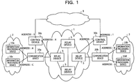
- FIG. 1 is a diagram illustrating a configuration example of a data communication system in a first embodiment.
- a network 1 is a wide area network provided by a telecommunications carrier, for instance.
- the network 1 includes a plurality of relay devices 5.
- Each of the relay devices 5 is, for instance, a router or a layer 3 switch.
- Each of the relay devices 5 performs routing so that a received packet is transmitted to a destination node of the packet.
- the data communication system includes a communication device 20a and a communication device 20b.
- the communication device 20a and the communication device 20b are devices having the firewall function.
- the firewall function may be achieved by a computer executing an application program to achieve the firewall function, or may be achieved by an Open Flow switch and the like.
- the communication device 20a and the communication device 20b may be achieved by a router.
- the communication device 20a and the communication device 20b may be achieved by a dedicated computer, or may be achieved by a general-purpose server and the like.
- a subnetwork 2 is coupled to the network 1 via the communication device 20a.
- a subnetwork 3 is coupled to the network 1 via the communication device 20b.
- the subnetwork 2 includes an information processing device that serves as a transmission source node of a packet or a destination node of a packet.
- an information processing device 10a and an information processing device 10c are included in the subnetwork 2.
- the subnetwork 2 is an in-house LAN, for instance.
- the subnetwork 3 includes an information processing device.
- the information processing device 10b and the information processing device 10d are included in the subnetwork 3.
- the communication device 20a is coupled to a control device 30a.
- the control device 30a controls the communication device 20a.
- the control device 30a may be formed of dedicated hardware, or may be achieved by NFV.
- the control device 30a is, for instance, a firewall controller or an Open Flow controller.
- the control device 30a controls setting and registration of a rule for the communication device 20a.
- the rule is a specification that stipulates whether a packet received by the communication device 20a is allowed to pass through or discarded.
- the communication device 20a allows passing of or discards a received packet based on a set and registered rule.
- the communication device 20b is coupled to a control device 30b.
- the control device 30b controls the communication device 20b.
- control device 30b controls setting and registration of a rule for the communication device 20b.
- the communication device 20b allows passing of or discards a received packet based on a set and registered rule.
- the control device 30a and the control device 30b are each coupled to the network 1, and each generate a packet such as a search packet, a notification packet, a rule setting request packet described later.
- the control device 30a and the control device 30b can transmit the generated packet to a predetermined destination node via the network 1.
- the control device 30a and the control device 30b may transmit the above-mentioned packet via another communication path 9 different from the network 1.
- the communication path 9 may be a communication path physically different from the network 1, or may be achieved by using part of a plurality of networks in which the network 1 is virtually divided by a virtual local area network (VLAN).
- VLAN virtual local area network
- FIG. 2 is a diagram illustrating a method of setting a rule in the first embodiment.
- FIG. 2 illustrates the flow of processing between the information processing device 10a, the control device 30a, the communication device 20a, the communication device 20b, the control device 30b, and the information processing device 10b.
- the information processing device 10a transmits a packet addressed to the information processing device 10b.
- the packet is provided with a header which includes a transmission source address, a destination address and the like of the packet.
- the packet transmitted by the information processing device 10a is transmitted in the network 1 via the communication device 20a, and arrives at the communication device 20b.
- the following description is given under the assumption that the packet is discarded based on a rule set and registered in the communication device 20b.
- the communication device 20b discards the packet.
- the communication device 20b notifies the control device 30b of the header information of the discarded packet. That is, the communication device 20b notifies the control device 30b of information on the transmission source address, the destination address and the like of the packet discarded by itself.
- the control device 30b In processing 504, the control device 30b generates a search packet based on the information notified from the communication device 20b.
- the search packet is a packet for searching for a communication device 20a between the information processing device 10a as a transmission source node of the discarded packet and the network 1, in other words, a communication device on the entry side.
- the control device 30b can identify the information processing device 10a which is the transmission source node of the discarded packet based on the header information notified from the communication device 20b.
- the control device 30b does not have information that identifies the communication device 20a which has allowed the packet to pass through in the network 1. For instance, a case where the control device 30b does not have the topology information on the entire data communication system.
- the control device 30b generates the above-described search packet.
- the search packet is a packet that designates the address of a transmission source node of the discarded packet as a destination address.
- a search packet designates the address "A" of the information processing device 10a as a destination address, and is transmitted from the control device 30b.
- the search packet is transmitted in the network 1, and arrives at the communication device 20a that manages the communication to the information processing device 10a. It is assumed that a rule stipulating that the search packet is discarded is pre-registered in the communication device 20a. In processing 505, the communication device 20a discards the search packet.
- the search packet designates the address of the information processing device 10a as the destination node
- the search packet has been generated to identify the communication device 20a and is not a packet to be transmitted actually to the information processing device 10a. Therefore, the search packet is discarded by the communication device 20a.
- the communication device 20a notifies the control device 30a of the header information of the search packet and information that identifies the communication device 20a.
- the header information of the search packet includes the address information on the control device 30b which is the transmission source node of the search packet.
- the control device 30a In processing 507, the control device 30a generates a notification packet based on the information notified from the communication device 20a.
- the notification packet is a packet for notifying the control device 30b of the information that identifies the communication device 20a, and the notification packet is received by the control device 30b, the control device 30b being a transmission source node of a search packet.
- the control device 30b can identify the communication device 20a that has allowed the packet discarded in processing 502 to pass through in the network 1.
- the control device 30b generates and transmits a rule setting request packet addressed to the control device 30a.
- the rule setting request packet includes information that identifies the communication device 20a which is a target device for setting a rule, and information that identifies the content of a rule set in the communication device 20a.
- the information that identifies the content of a rule is, for instance, information stipulating that a packet with a transmission source address, a destination address, a communication protocol, and a port number respectively matching the transmission source address, destination address, communication protocol, and port number of the packet discarded in processing 502 is to be discarded.
- the rule setting request packet is received by the control device 30a.
- the control device 30a commands the communication device 20a controlled by itself to set a rule.
- the communication device 20a sets a rule according to the command from the control device 30a.
- the information processing device 10a transmits a packet.
- the communication device 20a discards the packet in processing 512 in accordance with the rule set and registered in processing 510.
- the packet is not discarded when arriving at the exit-side communication device 20b after being transmitted in the network 1, but is discarded by the entry-side communication device 20a of the network 1. Therefore, the amount of communication in the network 1 can be suppressed. Furthermore, according to the first embodiment, even in the case where the control device 30b does not have the topology information on the entire data communication system, it is possible to identify the communication device 20a by generating a search packet.
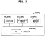
- FIG. 3 is a diagram illustrating a hardware configuration example of the communication device 20a and the communication device 20b. Since the communication device 20a and the communication device 20b may be formed of the same or similar hardware, the hardware configuration of the communication device 20a is described here.
- the communication device 20a includes a processor 200a, a nonvolatile memory 250a, a volatile memory 260a, a network interface card (NIC) 270a, and a bus 280a.
- NIC network interface card
- the processor 200a executes a computer program, thereby performing processing such as reception of a packet, determination as to whether a packet is allowed to pass through or discarded, and transmission or discard of a packet. In addition, when a packet is discarded, the processor 200a holds the header information of the discarded packet and notifies the control device 30a of the header information.
- a central processing unit CPU
- MCU micro control unit
- MPU micro processing unit
- DSP digital signal processor
- FPGA field programmable gate array
- nonvolatile memory 250a a computer program and the like to be executed by the processor 200a are stored.
- a hard disk drive (HDD) a read only memory (ROM), a mask read only memory (Mask ROM), a programmable read only memory (PROM), a flash memory, a magnetoresistive random access memory (MRAM), a resistance random access memory (ReRAM), a ferroelectric random access memory (FeRAM) and the like are applicable.
- HDD hard disk drive
- ROM read only memory
- Mask ROM mask read only memory
- PROM programmable read only memory
- flash memory a flash memory
- MRAM magnetoresistive random access memory
- ReRAM resistance random access memory
- FeRAM ferroelectric random access memory
- a computer program stored in the nonvolatile memory 250a is downloaded to the volatile memory 260a.
- the computer program downloaded to the volatile memory 260a is executed by the processor 200a.
- the volatile memory 260a holds data to be processed by the processor 200a or data which has been processed by the processor 200a.
- a dynamic random access memory (DRAM) and a static random access memory (SRAM) are applicable.
- the NIC 270a receives a packet transmitted from another node or transmits a received packet to another node.
- the bus 280a is coupled to the processor 200a, the nonvolatile memory 250a, the volatile memory 260a, and the NIC 270a, and serves as a mutual data communication path between the devices.
- FIG. 4 is a diagram illustrating a hardware configuration example of the control device 30a and the control device 30b. Since the control device 30a and the control device 30b may be formed of the same or similar hardware, the hardware configuration of the control device 30a is described here.
- the control device 30a includes a processor 300a, a nonvolatile memory 350a, a volatile memory 360a, a NIC 370a, and a bus 380a.
- the processor 300a executing a computer program, thereby performing predetermined data processing. For instance, the processor 300a receives the header information of a discarded packet from the communication device 20a, and generates a search packet, a notification packet, and a rule setting request packet. Also, the processor 300a, when receiving a rule setting request packet from the control device 30b, commands the communication device 20a to set a rule. The details of a search packet, a notification packet, and a rule change request packet are described later. As the processor 300a, a CPU, an MCU, an MPU, a DSP, a FPGA and the like are applicable, for instance.
- nonvolatile memory 350a In the nonvolatile memory 350a, a computer program and the like to be executed by the processor 300a are stored. As the nonvolatile memory 350a, a HDD, a ROM, a mask ROM, a PROM, a flash memory, an MRAM, a ReRAM, a FeRAM and the like are applicable.
- the computer program stored in the nonvolatile memory 350a is downloaded to the volatile memory 360a.
- the volatile memory 360a holds data to be processed by the processor 300a or data which has been processed by the processor 300a.
- a DRAM and a SRAM are applicable.
- the NIC 370a receives a packet transmitted from another node or transmits a received packet to another node.
- the bus 380a is coupled to the processor 300a, the nonvolatile memory 350a, the volatile memory 360a, and the NIC 370a, and serves as a mutual data communication path between the devices.
- FIG. 2 illustrates the processing in the case where the communication device 20a serves as the entry-side communication device, and the communication device 20b serves as the exit-side communication device, conversely there is also a case where the communication device 20b serves as the entry-side communication device, and the communication device 20a serves as the exit-side communication device.
- the communication device 20a performs the same processing described in FIG. 2 as the communication device 20b does, and the communication device 20b performs the same processing described in FIG. 2 as the communication device 20a does.
- the control device 30a performs the same processing described in FIG. 2 as the control device 30b does, and the control device 30b performs the same processing described in FIG. 2 as the control device 30a does.
- FIG. 5 is a functional block diagram of the processor 200a of the communication device 20a and the processor 200b of the communication device 20b. As described above, since the communication device 20a and the communication device 20b have an equivalent function and the processor 200a and the processor 200b also have an equivalent function, the function of the processor 200a is described here.
- the processor 200a downloads a computer program stored in the nonvolatile memory 250a for instance to the volatile memory 260a and executes the computer program, thereby serving as a rule table setting unit 201a, a packet processing unit 202a, a header information holding unit 203a, a determination unit 204a, a counter 205a, a timer 206a, a notification unit 207a, a packet transmission and reception unit 208a, a packet transmission and reception unit 209a, and a control signal reception unit 210a.
- the processor 200a also has a rule table 220a.
- the rule table 220a stores a rule for determining whether a received packet is allowed to pass through or discarded.
- the rule table 220a may be held in the processor 200a, and, for instance, may be held in the nonvolatile memory 250a or the volatile memory 260a.
- the rule table setting unit 201a sets a rule in the rule table 220a.
- the processing of setting a rule includes the processing of changing a rule already set and the processing of deleting a rule.
- the packet processing unit 202a refers to the content of a rule held in the rule table 220a, and thereby allows passing of or discards a received packet.
- the header information holding unit 203a holds the header information of the packet. In the example illustrated in FIG. 2 , when a packet is discarded in processing 502 or when a search packet is discarded in processing 505, the header information of each packet is held in header information holding unit 203a.
- the determination unit 204a determines whether or not the control device 30a is notified of the header information held in the header information holding unit 203a.
- the header information held in the header information holding unit 203a is the header information of a search packet
- count-up of the number of discarded packets by 1 by the counter 205a triggers the notification unit 207a to notify the control device 30a of the header information of the search packet.
- a notification packet is generated in the control device 30a as described later.
- the header information held in the header information holding unit 203a is not the header information of a search packet, but is the header information of the packet discarded in processing 502 of FIG.
- the notification unit 207a notifies the control device 30a of the header information based on a notification trigger signal issued by the timer 206a at predetermined time intervals. Also, the number of discarded packets having the same header content is counted by the counter 205a, and the control device 30a is notified of the number along with the header information.
- the packets having the same header content indicate a plurality of packets with respectively matching transmission source address, destination address, communication protocol, and port number. For these packets, the same determination is made in the communication device 20a as to whether each packet is allowed to pass through or discarded. In the present description, the packets having the same header content may be referred to as "packets belonging to the same flow". The technical significance of notifying the control device 30a of the number of discarded packets will be described later.
- the packet transmission and reception unit 208a transmits or receives a packet to or from the network 1.
- the packet transmission and reception unit 209a transmits or receives a packet to or from the subnetwork 2.
- the control signal reception unit 210a receives a control signal from the control device 30a.
- the control signal includes, for instance, a rule setting command to command the setting of the content of the rule table 220a.
- FIG. 6 is a functional block diagram of the processor 300a of the control device 30a and the processor 300b of the control device 30b. As described above, since the control device 30a and the control device 30b have an equivalent function and the processor 300a and the processor 300b also have an equivalent function, the function of the processor 300a is described here.
- the processor 300a downloads a computer program stored, for instance, in the nonvolatile memory 350a to the volatile memory 360a and executes the computer program, thereby serving as a notification reception unit 301a, a header information holding unit 302a, a determination unit 303a, an analysis unit 304a, a timer 305a, a search packet generation unit 306a, a notification packet generation unit 307a, a rule setting request packet generation unit 308a, a rule setting unit 309a, a packet transmission and reception unit 310a, and an error processing unit 311a.
- the processor 300a also has a management table 320a.
- the notification reception unit 301a receives a notification of header information from the communication device 20a controlled by itself.
- the notification reception unit 301a is notified from the communication device 20a of information indicating the number of discarded packets as well along with the header information.
- the header information holding unit 302a holds the header information and information on the number of discarded packets, received by the notification reception unit 301a.
- the determination unit 303a determines the type of a packet discarded in the communication device 20a, based on the header information held by the header information holding unit 302a. Specifically, the determination unit 303a determines whether the discarded packet is a search packet or another packet.
- the method of determining whether or not a discarded packet is a search packet includes, for instance, a method of referring to the port number of header information. As described later, the header information of a search packet is labeled with a port number, for instance, "555" indicating that the packet is a search packet.
- the determination unit 303a can determine whether or not a discarded packet is a search packet based on the port number of the header information.
- the analysis unit 304a conducts analysis to determine whether or not a search packet is generated for the discarded packet.
- a search packet As an example of content to be analyzed, for instance, it is analyzed whether or not a predetermined number or more of packets belonging to the same flow has been discarded within a predetermined time. Measurement of a predetermined time is made by the timer 305a.
- the search packet generation unit 306a When it is analyzed that a predetermined number or more of packets belonging to a specific flow has been discarded within a predetermined time, the search packet generation unit 306a generates a search packet.
- the destination node of the search packet is the transmission source node of the discarded packets, that is, the information processing device 10a in the first embodiment. Also, a packet ID corresponding to the flow is assigned to the search packet.
- the packet transmission and reception unit 310a transmits a search packet generated by the search packet generation unit 306a, and receives a search packet transmitted from another node.
- the information processing device 10b as a target may be attacked using a large number of packets or may be accessed in an unauthorized manner.
- a plurality of packets having the same header information is discarded together in a short period of time in the communication device 20b.
- the analysis unit 304a determines that the plurality of packets is for the purpose of attacking or making unauthorized access to a specific information processing device.
- the search packet generation unit 306a In order to inhibit such a plurality of packets from flowing into the network 1, the search packet generation unit 306a generates a search packet for searching for an information processing device on the entry side of the network 1. In this manner, it is possible to inhibit packets for the purpose of making unauthorized access from flowing into the network 1 and to efficiently reduce the amount of communication in the network 1.
- the notification packet generation unit 307a When it is determined that the packet discarded in the communication device 20a is a search packet, the notification packet generation unit 307a generates a notification packet.
- the notification packet is a packet notifying the transmission source node for a search packet of information that identifies a node which has discarded the search packet, that is, the communication device 20a in the first embodiment.
- the packet transmission and reception unit 310a transmits the notification packet generated by the notification packet generation unit 307a. Also, the packet transmission and reception unit 310a receives a notification packet transmitted from another node.
- the rule setting request packet generation unit 308a when receiving a notification packet from another node, for instance, the control device 30b, generates a rule setting request packet that requests the communication device 20b identified by the notification packet to set a rule. Also, when the packet transmission and reception unit 310a receives a rule setting request packet from another node, the rule setting unit 309a commands the rule table setting unit 201a to set a rule.
- the error processing unit 311a When a search packet is transmitted and a notification packet as a response to the search packet is not received after elapse of a certain time, the error processing unit 311a performs retransmission processing of the search packet as error processing. Similarly, when a notification packet is transmitted and a rule setting request packet as a response to the notification packet is not received after elapse of a certain time, the error processing unit 311a performs retransmission processing of the notification packet as error processing.
- a packet ID for identifying a search packet and the header information of a discarded packet are registered in association with each other.
- the packet ID is utilized for confirmation of the correspondence between a search packet and a notification packet.
- FIG. 7 is a table illustrating an example header information of a packet transmitted from the information processing device 10a addressed to the information processing device 10b in processing 501 illustrated in FIG. 2 .
- "A" which is the address of the information processing device 10a is registered as the transmission source address of the packet
- "B" which is the address of the information processing device 10b is registered as the destination address.
- TCP as a communication protocol
- "80" as a port number are registered.
- the port number is a number for identifying a program at a communication destination when an information processing device performs data communication.
- the packet Since the destination node of the packet is the information processing device 10b, the packet arrives at the communication device 20b that manages the communication to the information processing device 10b.
- the communication device 20b determines whether the packet is allowed to pass through or discarded based on the rule set and registered in the rule table 220b.
- FIG. 8 is a table illustrating an example rule which is held in the rule table 220b.
- a rule for transmission applied to a packet transmitted from the subnetwork 3 to the network 1 may be individually set.
- FIG. 8 illustrates an example rule for reception which is set and registered in the rule table 220b. The rule for reception may be set such that only a packet satisfying, for instance, one of the conditions set in the rule table 220b is allowed to pass through, and a packet satisfying none of the conditions set in the rule table 220b is discarded.
- FIG. 8 illustrates an example rule for reception which is set and registered in the rule table 220b. The rule for reception may be set such that only a packet satisfying, for instance, one of the conditions set in the rule table 220b is allowed to pass through, and a packet satisfying none of the conditions set in the rule table 220b is discarded.
- the communication device 20b which has received a packet transmitted from the information processing device 10a in processing 501 of FIG. 2 , refers to the rule registered in the rule table 220b.
- the packet illustrated in FIG. 7 is not registered as a packet that is allowed to pass through the communication device 20b in the rule illustrated in FIG. 8 . Therefore, the packet is discarded in the communication device 20b in processing 502 of FIG. 2 .
- FIG. 9 is a table illustrating an example header information of a search packet which is transmitted from the control device 30b in processing 504 of FIG. 2 .
- the address "Y" of the control device 30b is registered as the transmission source address
- the address "A" of the information processing device 10a which is the transmission source node of a packet discarded in the communication device 20b, is registered as the destination address.
- TCP as the communication protocol
- 555 as the port number
- a packet with a port number of "555" is a search packet is made between the communication device 20a, the communication device 20b, the control device 30a, and the control device 30b.
- the header of a search packet includes the packet ID of the search packet. In the example illustrated in FIG. 9 , " 1 " is set as the packet ID.
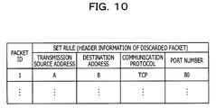
- FIG. 10 is a table, held in the management table 320a, illustrating the correspondence between the packet ID of a search packet and the header information of a discarded packet.
- the packet ID of a search packet is utilized for confirmation of the correspondence between a search packet and a notification packet.
- the header information of a discarded packet is utilized as the information indicating the content of a rule to be set when a rule setting request packet is generated.
- FIG. 11 is a table illustrating an example rule which is held in the communication device 20a that receives a search packet transmitted from the control device 30b in processing 504 of FIG. 2 .
- a rule for transmission applied to a packet transmitted from the subnetwork 2 to the network 1 may be individually set.
- an example of a rule for reception is illustrated. In the example illustrated in FIG.
- control device 30a is notified (processing 506 of FIG. 2 ) of the header information of the search packet by the notification unit 207a of the communication device 20a, and the header information is held in the header information holding unit 302a.
- a notification packet is generated by the notification packet generation unit 307a (processing 507 of FIG. 2 ).
- FIG. 12 is a table illustrating an example header information of a notification packet generated by the notification packet generation unit 307a.
- the address "X" of the control device 30a is registered as the transmission source address
- the address "Y" of the control device 30b which is the transmission source node of the search packet
- TCP as the communications protocol
- "666” as the port number are each registered.
- the notification packet generation unit 307a writes the same packet ID as the packet ID included in the header of the search packet.
- the control device 30b which has received a notification packet can check the notification packet against the search packet.
- the payload portion of a notification packet includes information that identifies the communication device 20a controlled by the control device 30a.
- the notification packet arrives at the control device 30b which is the transmission source node of the search packet via the network 1.
- the control device 30b which has received the notification packet can recognize the communication device 20a which is a search target node, based on the information included in the payload portion of the notification packet. Also, the control device 30b can recognize the address of the control device 30a which manages the communication device 20a, based on the header information of the notification packet.
- the rule setting request packet generation unit 308b then generates a rule setting request packet, and transmits it to the control device 30a.
- FIG. 13 is a table illustrating an example header information of a rule setting request packet generated in processing 508 of FIG. 2 .
- the address "Y" of the control device 30b as the transmission source address
- the address "X” of the control device 30a as the destination address
- "TCP” as the communication protocol
- "777" as the port number
- the payload portion of a rule setting request packet includes information that identifies the communication device 20a as information that identifies a target node for which a rule is set and registered.
- the payload portion includes information that identifies the content of a rule to be set and registered.
- the information stipulates that when a packet having header information with a transmission source address of "A”, a destination address of "B", a communication protocol of "TCP", and a port number of "80" is sent out from the subnetwork 2 to the network 1, the packet is discarded.
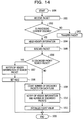
- FIG. 14 is a flow chart of processing performed by the processor 200a of the communication device 20a or the processor 200b of the communication device 20b.
- the processing flow performed by the processor 200a and the processing flow performed by the processor 200b are the same, and herein the processing flow performed by the processor 200a is described.
- the processing flow chart illustrated in FIG. 14 includes both cases where the communication device 20a is a communication device on the entry side and where the communication device 20a is a communication device on the exit side.
- the processing flow starts at processing 1000, and the packet transmission and reception unit 208a or the packet transmission and reception unit 209a receives a packet in processing 1001.
- the packet processing unit 202a determines processing for the packet (whether a packet is allowed to pass through or discarded) based on the rule registered in the rule table 220a.
- the processing flow proceeds to processing 1004, and when the content of processing for the packet is passing through, the processing flow proceeds to processing 1003.
- the packet processing unit 202a transfers the packet to the next node in processing 1003, and the processing flow ends in processing 1020.
- the header information holding unit 203a holds the header information of the packet in processing 1004.
- the packet processing unit 202a discards the packet in processing 1005.
- the determination unit 204a determines whether or not the discarded packet is a search packet. When it is determined that the discarded packet is a search packet, the processing flow proceeds to processing 1007, and when it is determined that the discarded packet is not a search packet, the processing flow proceeds to processing 1009.
- the notification unit 207a notifies the control device 30a of the header information of the search packet in processing 1007. Subsequently, in processing 1008, the rule table setting unit 201a sets a rule based on a rule setting command from the control device 30a, and the processing flow ends in processing 1020.
- the counter 205a counts the number of discarded packets for each flow in processing 1009.
- the notification unit 207a notifies the control device 30a of the header information of discarded packets and the number of discarded packets for each flow based on a notification trigger signal issued by the timer 206a.
- the counter 205a initializes a count value, and the processing flow ends in processing 1020.
- the header information and the like held in the header information holding unit 203a may be transmitted to the control device 30a based on a notification trigger signal regardless of the reception processing of a packet.
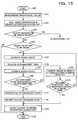
- FIG. 15 is a flow chart of processing flow performed by the processor 300a of the control device 30a or the processor 300b of the control device 30b.
- the processing flow performed by the processor 300a and the processing flow performed by the processor 300b are the same, and herein the processing flow performed by the processor 300a is described.
- the processing flow chart illustrated in FIG. 15 includes both cases where the control device 30a generates a search packet and where the control device 30a receives a search packet.
- the processing flow starts at processing 1100, and the notification reception unit 301a receives the header information and the like of a discarded packet from the communication device 20a in processing 1101.
- the information received by the notification reception unit 301a from the communication device 20a may also include information indicating the number of discarded packets in addition to the header information.
- the header information holding unit 302a holds the header information and the like received in processing 1101.
- the determination unit 303a determines whether or not the header information held in the header information holding unit 302a is the header information of a search packet.
- the processing flow proceeds to processing 1201 (described below) of FIG. 16 .
- the processing flow proceeds to processing 1104.
- the analysis unit 304a conducts analysis to determine whether or not a search packet has to be issued, based on the number of discarded packets and the like. When it is determined that no search packet has to be issued, the processing flow is terminated in processing 1120. When it is determined that a search packet has to be issued, the search packet generation unit 306a generates a search packet in processing 1105. In processing 1106, the search packet generation unit 306a registers the packet ID of the generated search packet and the header information of discarded packets in association with each other in the management table 320a. In processing 1107, the packet transmission and reception unit 310a transmits the generated search packet.
- the error processing unit 311a determines whether or not a notification packet has been received by the packet transmission and reception unit 310a within a certain time since the transmission of a search packet. When a notification packet is not received within a predetermined time, in processing 1109, the error processing unit 311a increments a count value to record the number of generation times of a search packet by 1. In processing 1110, the error processing unit 311a determines whether or not the number of generation times of a search packet has exceeded a predetermined value. When it is determined that the number of generation times of a search packet has not exceeded a predetermined value, the processing flow returns to processing 1105 and a search packet is generated again. On the other hand, when it is determined that the number of generation times of a search packet has exceeded a predetermined value, the processing flow proceeds from processing 1110 to processing 1113.
- the rule setting request packet generation unit 308a When it is determined that a notification packet has been received within a predetermined time in processing 1108, in processing 1111, the rule setting request packet generation unit 308a generates a rule setting request packet. In processing 1112, the packet transmission and reception unit 310a transmits the generated rule setting request packet. In processing 1113, the header information holding unit 302a deletes the header information held by itself. Subsequently, the processing flow ends in processing 1120.
- FIG. 16 is part of flow chart of the processing flow performed by the processor 300a of the control device 30a or the processor 300b of the control device 30b, and is a flow chart of the processing flow following processing 1103 disclosed in FIG. 15 .
- the processing flow performed by the processor 300a and the processing flow performed by the processor 300b are the same, and herein the processing flow performed by the processor 300a is described.
- the notification packet generation unit 307a When it is determined in processing 1103 that the header information held in the header information holding unit 302a is the header information of a search packet, in processing 1201, the notification packet generation unit 307a generates a notification packet. In processing 1202, the packet transmission and reception unit 310a transmits the generated notification packet. In processing 1203, the error processing unit 311a determines whether or not a rule setting request packet has been received by the packet transmission and reception unit 310a within a predetermined time after the transmission of the notification packet. When a rule setting request packet has not been received within a predetermined time, the processing flow proceeds to processing 1204, and when a rule setting request packet has been received within a predetermined time, the processing flow proceeds to processing 1206.
- the error processing unit 311a increments a count value to record the number of generation times of a notification packet by 1. In processing 1205, the error processing unit 311a then determines whether or not the number of generation times of a notification packet has exceeded a predetermined value. When it is determined that the number of generation times of a notification packet has not exceeded a predetermined value, the processing flow returns to processing 1201 and a notification packet is generated again. When it is determined that the number of generation times of a notification packet has exceeded a predetermined value, the processing flow proceeds from processing 1205 to processing 1207.
- the rule setting unit 309a commands the rule table setting unit 201a of the communication device 20a to set a rule. Subsequently, in processing 1207, the header information holding unit 302a deletes the header information held by itself, and the processing flow ends in processing 1220.
- FIG. 17 is a table illustrating an example rule which is held in the rule table 220a.
- a rule for transmission set in processing 510 of FIG. 2 is disclosed.
- a rule is set that stipulates that a packet having header information with a transmission source address of "A”, a destination address of "B", a communication protocol of "TCP", and a port number of "80" is discarded in the communication device 20a, and other packets (* in FIG. 17 ) are allowed to pass through the communication device 20a. Consequently, a packet having the above-described header information is not discarded in the communication device 20b on the exit side of the network 1, but is discarded in the communication device 20a on the entry side of the network 1.
- a rule when a packet is discarded in the communication device 20a or the communication device 20b on the exit side of the network 1, a rule can be set in the communication device 20b or the communication device 20a on the entry side of the network 1. Also, even when the control device 30a or the control device 30b does not have the topology information on the entire data communication system, the communication device 20a or the communication device 20b on the entry side can be identified, and it is possible to set a rule in the communication device 20a or the communication device 20b on the entry side.
- communication of a notification packet and a rule setting request packet performed between the communication device 20a and the communication device 20b has been described by way of an example which is performed using a packet transmission and reception port, for the network 1, of the communication device 20a, and a packet transmission and reception port, for the network 1, of the communication device 20b.
- the control device 30a and the control device 30b may perform communication using the packet transmission and reception port labeled with the address "S", for the communication path 9, of the control device 30a, and the packet transmission and reception port labeled with the address "T", for the communication path 9, of the control device 30b.
- Use of the communication path 9 separated from the network 1 makes it possible to avoid transmission of a notification packet and a rule setting request packet by a node not coupled to the communication path 9, the node impersonating the control device 30a or the control device 30b.
- the communication device 20a and the control device 30a are illustrated as separate devices in the first embodiment, the embodiments of the present disclosure are not limited to this.
- a firewall including the function of the communication device 20a and the function of the control device 30a may be provided between the network 1 and the subnetwork 2.
- the communication device 20b and the control device 30b may not be achieved as separate devices.
- the network 1 may not be a wide area network provided by a single telecommunications carrier.
- the network 1 may include a plurality of different wide area networks provided by different telecommunications carriers.
- information on the specification of a search packet, a notification packet, and a rule setting request packet is shared between the control device 30a and the control devices 30b. Consequently, even when the network 1 includes a plurality of wide area networks, a rule can be set in the entry-side communication device 20a.
- control device 30a and the control device 30b control the communication device 20a and the communication device 20b, respectively.
- control device 30a controls both the communication device 20a and the communication device 20b.
- FIG. 18 is a diagram illustrating a configuration example of a data communication system in the second embodiment.
- the same components as those disclosed in FIG. 1 are labeled with the same symbol, and a description is omitted.
- Each of the communication device 20a and the communication device 20b is controlled by the control device 30a.
- the control device 30a is coupled to the network 1 and able to transmit and receive a packet. It is assumed that an address "Z" is assigned to the control device 30a.
- the control device 30a may be achieved by the hardware configuration illustrated in FIG. 3 .
- FIG. 19 is a diagram illustrating a processing method for rule setting and registration in the second embodiment.
- the information processing device 10a transmits a packet addressed to the information processing device 10b.
- the header information of the packet is assumed to be the same as the header information illustrated in FIG. 7 .
- a packet transmitted from the information processing device 10a passes through the communication device 20a, and arrives at the communication device 20b. It is assumed that the same rule as the rule illustrated in FIG. 8 is set and registered in the communication device 20b.
- the communication device 20b discards the packet based on a rule set and registered.
- the communication device 20b notifies the control device 30a of the header information of the discarded packet.
- the control device 30a generates a search packet.
- the header information of the search packet is assumed to be the same as the header information of the search packet illustrated in FIG. 9 .
- the transmission source address is not "Y" illustrated in FIG. 9 but the address "Z" of the control device 30a in the second embodiment. Registration to the management table 320a illustrated in FIG. 10 is made based on the generation of the search packet.
- the search packet is generated with a destination node of the information processing device 10a, and is transmitted from the control device 30a.
- the search packet is transmitted in the network 1, and arrives at the communication device 20a that manages the communication to the information processing device 10a. It is assumed that the rule for reception illustrated in FIG. 11 is set and registered in the communication device 20a.
- the communication device 20a discards the search packet based on the above-described rule for reception.
- the communication device 20a notifies the control device 30a of the header information of the search packet.
- the header information includes packet ID. At this point, the communication device 20a notifies the control device 30a of information that identifies the communication device 20a.
- the control device 30a refers to the management table 320a based on the packet ID included in the header information of the packet notified from the communication device 20a, and identifies the header information of a corresponding discarded packet.
- the control device 30a commands the communication device 20a to set a rule based on the header information of the discarded packet registered in the management table 320a.
- the communication device 20a sets a rule based on the command from the control device 30a.
- the information processing device 10a transmits a packet. It is assumed that the packet transmitted here and the packet transmitted in processing 601 belong to the same flow.
- the communication device 20a discards the packet in processing 610 in accordance with the rule set and registered in processing 608.
- the packet is discarded in the communication device 20a on the entry side of the network 1. Therefore, the amount of communication in the network 1 can be suppressed.
- the control device 30a does not have the topology information on the entire data communication system, it is possible to identify the communication device 20a by generating a search packet.
- both the communication device 20a and the communication device 20b are controlled by the control device 30a, and thus a rule can be set in the communication device 20a without using the notification packet or the rule setting request packet disclosed in the first embodiment.
- the same functional block as the functional block illustrated in FIG. 5 is applicable.
- the same functional block as the functional block illustrated in FIG. 6 is applicable. However, since a notification packet and a rule setting request packet are not generated in the second embodiment, the notification packet generation unit 307a and the rule setting request packet generation unit 308a of the functional block illustrated in FIG. 6 can be omitted.
- FIG. 20 is a flow chart of processing performed by the processor 300a of the control device 30a in the second embodiment.
- the same processing as in the flow chart (see FIG. 15 ) of the processor 300a in the first embodiment is labeled with the same reference symbol, and a description is omitted.
- processing 1100 to processing 1107 the same processing as in the first embodiment is performed.
- the error processing unit 311a determines whether or not a notification of the header information of a search packet is received from the communication device 20a within a predetermined time since transmission of the search packet.
- the processing flow proceeds to processing 1109, and when a notification of the header information of the search packet is received within a predetermined time, the processing flow proceeds to processing 1302.
- the rule setting unit 309a commands the rule table setting unit 201a of the communication device 20a to set a rule.
- the header information holding unit 302a deletes the header information related to the flow in which a rule is set, out of the header information held by itself, and in processing 1120, the processing flow ends.
- the processing flow proceeds to processing 1302, and the rule setting unit 309a commands the rule table setting unit 201a to set a rule.
Landscapes
- Engineering & Computer Science (AREA)
- Computer Networks & Wireless Communication (AREA)
- Signal Processing (AREA)
- Computer Security & Cryptography (AREA)
- Computer Hardware Design (AREA)
- Computing Systems (AREA)
- General Engineering & Computer Science (AREA)
- Business, Economics & Management (AREA)
- General Business, Economics & Management (AREA)
- Data Exchanges In Wide-Area Networks (AREA)
Abstract
Description
- The present disclosure relates to a method and a communication system.
- The firewall is known as a technology to avoid attack and unauthorized access from an external network and to protect information processing devices such as a server coupled into a subnetwork such as a local area network (LAN). A communication device which performs the function of the firewall is provided between a network and a LAN, for instance, and receives a packet flowing from the network into the LAN or a packet flowing out from the LAN to the network. The communication device determines whether a packet received by the communication device is allowed to pass through or discarded. The function of the firewall may be achieved by a dedicated device or may be achieved by executing an application program on a general-purpose server or by an Open Flow switch or the like.
- For instance, a rule is set and registered in the communication device, the rule stipulating that a packet transmitted from a specific information processing device coupled to the network addressed to another specific information processing device included in the LAN is allowed to pass through. Thus, the communication device allows a packet satisfying the set and registered rule to pass through and can discard other packets. As another example, a rule is set and registered in the communication device, the rule stipulating that a packet transmitted from a specific information processing device in a LAN addressed to another specific information processing device via a network is discarded. Thus, the communication device can discard a packet satisfying the set and registered rule and allows other packets to pass through. A rule set and registered in the communication device may be called a policy or an entry.
- Here, in a data communication system in which a first LAN is coupled to a network via a first communication device and a second LAN is coupled to the network via a second communication device, a case is assumed in which a first information processing device in the first LAN transmits a packet addressed to a second information processing device in the second LAN. As a precondition, it is assumed that a rule is not set and registered in the second communication device, the rule stipulating that a packet with a transmission source node of the first information processing device and a destination node of the second information processing device is allowed to pass through. First, a packet transmitted from the first information processing device is received by the first communication device. The first communication device is disposed on the entry side of the network for the packet, and thus is called the entry-side communication device. A packet sent out to the network via the entry-side communication device flows through the network and arrives at the second communication device. The second communication device is disposed on the exit side of the network for the packet, and thus is called the exit-side communication device. Here, the second communication device determines whether the packet is allowed to pass through or discarded in accordance with the rule set and registered in itself. Here, for a packet with a transmission source node of the first information processing device and a destination node of the second information processing device, a rule stipulating that the packet is a passing target is not set and registered in the second communication device, and thus the packet is discarded in the second communication device.
- A method is known in which after a packet is transmitted in the network, a packet to be discarded in the second (exit-side) communication device is not discarded in the second communication device but is discarded in the first (entry-side) communication device. For instance, when the second communication device discards a packet which is transmitted from the first information processing device addressed to the second information processing device, the first communication device that manages the communication of the first information processing device is identified based on the topology information on the entire data communication system including the LAN. The second communication device then requests the identified first communication device to discard any packet belonging to the same flow without allowing the packet to pass through. The first communication device updates the rule of itself based on the request from the second communication device. Hereinafter, the first communication device discards any packet which is transmitted from the first information processing device addressed to the second information processing device without transmitting the packet to the network. Consequently, the amount of communication in the network can be suppressed. Related art documents include Japanese Laid-open Patent Publication Nos.
2015-91106 2004-159117 - In the above-described prior art, in order for the exit-side communication device to request the entry-side communication device to stop allowing a specific packet to pass through, it is desired to identify the entry-side communication device that manages the communication of the first information processing device that has transmitted the packet. In order to identify the entry-side communication device, the topology information on the data communication system is utilized.
- It is an object of the present disclosure to provide a method that, when the exit-side communication device discards a packet, is capable of identifying an entry-side communication device of the packet without using the topology information on the data communication system, and of setting a rule in the entry-side communication device.
- According to an aspect of the invention, a method using a communication system including a first information processing device, a first communication device configured to relay packet communication between a network and the first information processing device, a first control device configured to control the first communication device, a second information processing device, and a second communication device configured to relay packet communication between the network and the second information processing device, the method includes transmitting, from the first information processing device to the network via the first communication device, a first packet which belongs to a first flow, a destination node of the first packet being the second information processing device, receiving, by the second communication device, the first packet, discarding, by the second communication device, the first packet based on a first rule stipulating that a packet belonging to the first flow is to be discarded, identifying, based on first header information of the discarded first packet, the first information processing device which is a transmission source node of the first packet, transmitting, to the network, a second packet of which a destination node is the identified first information processing device, receiving, by the first communication device, the second packet, based on the receiving of the second packet, setting, by the first control device, the first rule to the first communication device, after the setting of the first rule to the first communication device, transmitting, from the first information processing device, a third packet which belongs to the first flow, receiving, by the first communication device, the third packet, and discarding, by the first communication device, the third packet based on the first rule.
- According to the present disclosure, when the exit-side communication device discards a packet, an entry-side communication device of the packet can be identified without using the topology information on the data communication system, and a rule can be set in the entry-side communication device.
-
-
FIG. 1 is a diagram illustrating a configuration example of a data communication system in a first embodiment; -
FIG. 2 is a diagram illustrating a method of setting a rule in the first embodiment; -
FIG. 3 is a diagram illustrating a hardware configuration example of a communication device in the first embodiment; -
FIG. 4 is a diagram illustrating a hardware configuration example of a control device in the first embodiment; -
FIG. 5 is a functional block diagram of the communication device in the first embodiment; -
FIG. 6 is a functional block diagram of the control device in the first embodiment; -
FIG. 7 is a table illustrating an example header information of a packet discarded by the communication device in the first embodiment; -
FIG. 8 is a table illustrating an example rule which is set and registered in the communication device in the first embodiment; -
FIG. 9 is a table illustrating an example header information of a search packet generated by the control device in the first embodiment; -
FIG. 10 is a table for explaining identification (ID) of a search packet in the first embodiment; -
FIG. 11 is a table illustrating an example rule which is set and registered in the communication device in the first embodiment; -
FIG. 12 is a table illustrating an example header information of a notification packet generated by the control device in the first embodiment; -
FIG. 13 is a table illustrating an example header information of a rule setting request packet generated by the control device in the first embodiment; -
FIG. 14 is a flow chart of processing performed by a processor of the communication device in the first embodiment; -
FIG. 15 is a flow chart of processing performed by a processor of the control device in the first embodiment; -
FIG. 16 is a flow chart of processing performed by the processor of the control device in the first embodiment; -
FIG. 17 is a table illustrating an example rule which is set and registered in the communication device in the first embodiment; -
FIG. 18 is a diagram illustrating a configuration example of a data communication system in a second embodiment; -
FIG. 19 is a diagram illustrating a method of setting a rule in the second embodiment; and -
FIG. 20 is a flow chart of processing performed by a processor of a control device in the second embodiment. -
FIG. 1 is a diagram illustrating a configuration example of a data communication system in a first embodiment. Anetwork 1 is a wide area network provided by a telecommunications carrier, for instance. Thenetwork 1 includes a plurality ofrelay devices 5. Each of therelay devices 5 is, for instance, a router or alayer 3 switch. Each of therelay devices 5 performs routing so that a received packet is transmitted to a destination node of the packet. - In
FIG. 1 , the data communication system includes acommunication device 20a and acommunication device 20b. Thecommunication device 20a and thecommunication device 20b are devices having the firewall function. The firewall function may be achieved by a computer executing an application program to achieve the firewall function, or may be achieved by an Open Flow switch and the like. Also, thecommunication device 20a and thecommunication device 20b may be achieved by a router. Also, thecommunication device 20a and thecommunication device 20b may be achieved by a dedicated computer, or may be achieved by a general-purpose server and the like. A subnetwork 2 is coupled to thenetwork 1 via thecommunication device 20a. Also, asubnetwork 3 is coupled to thenetwork 1 via thecommunication device 20b. The subnetwork 2 includes an information processing device that serves as a transmission source node of a packet or a destination node of a packet. In the example illustrated inFIG. 1 , aninformation processing device 10a and aninformation processing device 10c are included in the subnetwork 2. The subnetwork 2 is an in-house LAN, for instance. Similarly, thesubnetwork 3 includes an information processing device. InFIG. 1 , theinformation processing device 10b and theinformation processing device 10d are included in thesubnetwork 3. - The
communication device 20a is coupled to acontrol device 30a. Thecontrol device 30a controls thecommunication device 20a. Thecontrol device 30a may be formed of dedicated hardware, or may be achieved by NFV. Thecontrol device 30a is, for instance, a firewall controller or an Open Flow controller. Thecontrol device 30a controls setting and registration of a rule for thecommunication device 20a. The rule is a specification that stipulates whether a packet received by thecommunication device 20a is allowed to pass through or discarded. Thecommunication device 20a allows passing of or discards a received packet based on a set and registered rule. Similarly to thecommunication device 20a, thecommunication device 20b is coupled to acontrol device 30b. Thecontrol device 30b controls thecommunication device 20b. Specifically, thecontrol device 30b controls setting and registration of a rule for thecommunication device 20b. Thecommunication device 20b allows passing of or discards a received packet based on a set and registered rule. Thecontrol device 30a and thecontrol device 30b are each coupled to thenetwork 1, and each generate a packet such as a search packet, a notification packet, a rule setting request packet described later. Also, thecontrol device 30a and thecontrol device 30b can transmit the generated packet to a predetermined destination node via thenetwork 1. Also, thecontrol device 30a and thecontrol device 30b may transmit the above-mentioned packet via another communication path 9 different from thenetwork 1. The communication path 9 may be a communication path physically different from thenetwork 1, or may be achieved by using part of a plurality of networks in which thenetwork 1 is virtually divided by a virtual local area network (VLAN). - As illustrated in
FIG. 1 , in the first embodiment, let "A" be the address of theinformation processing device 10a, "B" be the address of theinformation processing device 10b, "C" be the address of theinformation processing device 10c, and "D" be the address of theinformation processing device 10d. In addition, in the first embodiment, let "X" be the address of a transmission and reception port, coupled to thenetwork 1, of thecontrol device 30a, "S" be the address of a transmission and reception port, coupled to the communication path 9, of thecontrol device 30a, "Y" be the address of a transmission and reception port, coupled to thenetwork 1, of thecontrol device 30b, and "T" be the address of a transmission and reception port, coupled to the communication path 9, of thecontrol device 30b. The address is, for instance, an IP address. -
FIG. 2 is a diagram illustrating a method of setting a rule in the first embodiment.FIG. 2 illustrates the flow of processing between theinformation processing device 10a, thecontrol device 30a, thecommunication device 20a, thecommunication device 20b, thecontrol device 30b, and theinformation processing device 10b. Inprocessing 501, theinformation processing device 10a transmits a packet addressed to theinformation processing device 10b. The packet is provided with a header which includes a transmission source address, a destination address and the like of the packet. The packet transmitted by theinformation processing device 10a is transmitted in thenetwork 1 via thecommunication device 20a, and arrives at thecommunication device 20b. Here, the following description is given under the assumption that the packet is discarded based on a rule set and registered in thecommunication device 20b. Inprocessing 502, thecommunication device 20b discards the packet. Inprocessing 503, thecommunication device 20b notifies thecontrol device 30b of the header information of the discarded packet. That is, thecommunication device 20b notifies thecontrol device 30b of information on the transmission source address, the destination address and the like of the packet discarded by itself. - In
processing 504, thecontrol device 30b generates a search packet based on the information notified from thecommunication device 20b. The search packet is a packet for searching for acommunication device 20a between theinformation processing device 10a as a transmission source node of the discarded packet and thenetwork 1, in other words, a communication device on the entry side. At this point, thecontrol device 30b can identify theinformation processing device 10a which is the transmission source node of the discarded packet based on the header information notified from thecommunication device 20b. However, in some cases, thecontrol device 30b does not have information that identifies thecommunication device 20a which has allowed the packet to pass through in thenetwork 1. For instance, a case where thecontrol device 30b does not have the topology information on the entire data communication system. Thus, thecontrol device 30b generates the above-described search packet. The search packet is a packet that designates the address of a transmission source node of the discarded packet as a destination address. In the first embodiment, a search packet designates the address "A" of theinformation processing device 10a as a destination address, and is transmitted from thecontrol device 30b. The search packet is transmitted in thenetwork 1, and arrives at thecommunication device 20a that manages the communication to theinformation processing device 10a. It is assumed that a rule stipulating that the search packet is discarded is pre-registered in thecommunication device 20a. Inprocessing 505, thecommunication device 20a discards the search packet. That is, although the search packet designates the address of theinformation processing device 10a as the destination node, the search packet has been generated to identify thecommunication device 20a and is not a packet to be transmitted actually to theinformation processing device 10a. Therefore, the search packet is discarded by thecommunication device 20a. Inprocessing 506, thecommunication device 20a notifies thecontrol device 30a of the header information of the search packet and information that identifies thecommunication device 20a. The header information of the search packet includes the address information on thecontrol device 30b which is the transmission source node of the search packet. - In
processing 507, thecontrol device 30a generates a notification packet based on the information notified from thecommunication device 20a. The notification packet is a packet for notifying thecontrol device 30b of the information that identifies thecommunication device 20a, and the notification packet is received by thecontrol device 30b, thecontrol device 30b being a transmission source node of a search packet. Inprocessing 508, with the notification packet, thecontrol device 30b can identify thecommunication device 20a that has allowed the packet discarded inprocessing 502 to pass through in thenetwork 1. Thus, inprocessing 508, thecontrol device 30b generates and transmits a rule setting request packet addressed to thecontrol device 30a. The rule setting request packet includes information that identifies thecommunication device 20a which is a target device for setting a rule, and information that identifies the content of a rule set in thecommunication device 20a. The information that identifies the content of a rule is, for instance, information stipulating that a packet with a transmission source address, a destination address, a communication protocol, and a port number respectively matching the transmission source address, destination address, communication protocol, and port number of the packet discarded inprocessing 502 is to be discarded. - The rule setting request packet is received by the
control device 30a. Inprocessing 509, thecontrol device 30a commands thecommunication device 20a controlled by itself to set a rule. Inprocessing 510, thecommunication device 20a sets a rule according to the command from thecontrol device 30a. Subsequently, inprocessing 511, theinformation processing device 10a transmits a packet. In the case where the transmission source address, destination address, communication protocol, and port number of the packet transmitted in processing 511 respectively match the transmission source address, destination address, communication protocol, and port number of the packet discarded by thecommunication device 20b inprocessing 502, thecommunication device 20a discards the packet inprocessing 512 in accordance with the rule set and registered inprocessing 510. Thus, the packet is not discarded when arriving at the exit-side communication device 20b after being transmitted in thenetwork 1, but is discarded by the entry-side communication device 20a of thenetwork 1. Therefore, the amount of communication in thenetwork 1 can be suppressed. Furthermore, according to the first embodiment, even in the case where thecontrol device 30b does not have the topology information on the entire data communication system, it is possible to identify thecommunication device 20a by generating a search packet. -
FIG. 3 is a diagram illustrating a hardware configuration example of thecommunication device 20a and thecommunication device 20b. Since thecommunication device 20a and thecommunication device 20b may be formed of the same or similar hardware, the hardware configuration of thecommunication device 20a is described here. Thecommunication device 20a includes aprocessor 200a, anonvolatile memory 250a, avolatile memory 260a, a network interface card (NIC) 270a, and abus 280a. - The
processor 200a executes a computer program, thereby performing processing such as reception of a packet, determination as to whether a packet is allowed to pass through or discarded, and transmission or discard of a packet. In addition, when a packet is discarded, theprocessor 200a holds the header information of the discarded packet and notifies thecontrol device 30a of the header information. As theprocessor 200a, for instance, a central processing unit (CPU), a micro control unit (MCU), a micro processing unit (MPU), a digital signal processor (DSP), a field programmable gate array (FPGA) and the like are applicable. - In the
nonvolatile memory 250a, a computer program and the like to be executed by theprocessor 200a are stored. As thenonvolatile memory 250a, a hard disk drive (HDD), a read only memory (ROM), a mask read only memory (Mask ROM), a programmable read only memory (PROM), a flash memory, a magnetoresistive random access memory (MRAM), a resistance random access memory (ReRAM), a ferroelectric random access memory (FeRAM) and the like are applicable. - A computer program stored in the
nonvolatile memory 250a is downloaded to thevolatile memory 260a. The computer program downloaded to thevolatile memory 260a is executed by theprocessor 200a. Also, thevolatile memory 260a holds data to be processed by theprocessor 200a or data which has been processed by theprocessor 200a. As thevolatile memory 260a, a dynamic random access memory (DRAM) and a static random access memory (SRAM) are applicable. - The
NIC 270a receives a packet transmitted from another node or transmits a received packet to another node. Thebus 280a is coupled to theprocessor 200a, thenonvolatile memory 250a, thevolatile memory 260a, and theNIC 270a, and serves as a mutual data communication path between the devices. -
FIG. 4 is a diagram illustrating a hardware configuration example of thecontrol device 30a and thecontrol device 30b. Since thecontrol device 30a and thecontrol device 30b may be formed of the same or similar hardware, the hardware configuration of thecontrol device 30a is described here. Thecontrol device 30a includes aprocessor 300a, anonvolatile memory 350a, avolatile memory 360a, aNIC 370a, and abus 380a. - The
processor 300a executing a computer program, thereby performing predetermined data processing. For instance, theprocessor 300a receives the header information of a discarded packet from thecommunication device 20a, and generates a search packet, a notification packet, and a rule setting request packet. Also, theprocessor 300a, when receiving a rule setting request packet from thecontrol device 30b, commands thecommunication device 20a to set a rule. The details of a search packet, a notification packet, and a rule change request packet are described later. As theprocessor 300a, a CPU, an MCU, an MPU, a DSP, a FPGA and the like are applicable, for instance. - In the
nonvolatile memory 350a, a computer program and the like to be executed by theprocessor 300a are stored. As thenonvolatile memory 350a, a HDD, a ROM, a mask ROM, a PROM, a flash memory, an MRAM, a ReRAM, a FeRAM and the like are applicable. - The computer program stored in the
nonvolatile memory 350a is downloaded to thevolatile memory 360a. Also, thevolatile memory 360a holds data to be processed by theprocessor 300a or data which has been processed by theprocessor 300a. As thevolatile memory 360a, a DRAM and a SRAM are applicable. TheNIC 370a receives a packet transmitted from another node or transmits a received packet to another node. Thebus 380a is coupled to theprocessor 300a, thenonvolatile memory 350a, thevolatile memory 360a, and theNIC 370a, and serves as a mutual data communication path between the devices. - Next, the function of the
communication device 20a and thecommunication device 20b and the function of thecontrol device 30a and thecontrol device 30b are disclosed. In the first embodiment, thecommunication device 20a and thecommunication device 20b have an equivalent function, and thecontrol device 30a and thecontrol device 30b have an equivalent function. In other words, althoughFIG. 2 illustrates the processing in the case where thecommunication device 20a serves as the entry-side communication device, and thecommunication device 20b serves as the exit-side communication device, conversely there is also a case where thecommunication device 20b serves as the entry-side communication device, and thecommunication device 20a serves as the exit-side communication device. For instance, in the case where a packet transmitted from theinformation processing device 10b to theinformation processing device 10a is discarded in thecommunication device 20a, thecommunication device 20a performs the same processing described inFIG. 2 as thecommunication device 20b does, and thecommunication device 20b performs the same processing described inFIG. 2 as thecommunication device 20a does. In this case, thecontrol device 30a performs the same processing described inFIG. 2 as thecontrol device 30b does, and thecontrol device 30b performs the same processing described inFIG. 2 as thecontrol device 30a does. -
FIG. 5 is a functional block diagram of theprocessor 200a of thecommunication device 20a and theprocessor 200b of thecommunication device 20b. As described above, since thecommunication device 20a and thecommunication device 20b have an equivalent function and theprocessor 200a and theprocessor 200b also have an equivalent function, the function of theprocessor 200a is described here. - The
processor 200a downloads a computer program stored in thenonvolatile memory 250a for instance to thevolatile memory 260a and executes the computer program, thereby serving as a ruletable setting unit 201a, apacket processing unit 202a, a headerinformation holding unit 203a, adetermination unit 204a, acounter 205a, atimer 206a, anotification unit 207a, a packet transmission andreception unit 208a, a packet transmission andreception unit 209a, and a controlsignal reception unit 210a. Theprocessor 200a also has a rule table 220a. The rule table 220a stores a rule for determining whether a received packet is allowed to pass through or discarded. The rule table 220a may be held in theprocessor 200a, and, for instance, may be held in thenonvolatile memory 250a or thevolatile memory 260a. - The rule
table setting unit 201a sets a rule in the rule table 220a. In addition to the processing of writing a rule, the processing of setting a rule includes the processing of changing a rule already set and the processing of deleting a rule. Thepacket processing unit 202a refers to the content of a rule held in the rule table 220a, and thereby allows passing of or discards a received packet. When a packet is discarded by thepacket processing unit 202a, the headerinformation holding unit 203a holds the header information of the packet. In the example illustrated inFIG. 2 , when a packet is discarded inprocessing 502 or when a search packet is discarded inprocessing 505, the header information of each packet is held in headerinformation holding unit 203a. - The
determination unit 204a determines whether or not thecontrol device 30a is notified of the header information held in the headerinformation holding unit 203a. When the header information held in the headerinformation holding unit 203a is the header information of a search packet, count-up of the number of discarded packets by 1 by thecounter 205a triggers thenotification unit 207a to notify thecontrol device 30a of the header information of the search packet. In this case, a notification packet is generated in thecontrol device 30a as described later. On the other hand, when the header information held in the headerinformation holding unit 203a is not the header information of a search packet, but is the header information of the packet discarded in processing 502 ofFIG. 2 , for instance, thenotification unit 207a notifies thecontrol device 30a of the header information based on a notification trigger signal issued by thetimer 206a at predetermined time intervals. Also, the number of discarded packets having the same header content is counted by thecounter 205a, and thecontrol device 30a is notified of the number along with the header information. In the first embodiment, the packets having the same header content indicate a plurality of packets with respectively matching transmission source address, destination address, communication protocol, and port number. For these packets, the same determination is made in thecommunication device 20a as to whether each packet is allowed to pass through or discarded. In the present description, the packets having the same header content may be referred to as "packets belonging to the same flow". The technical significance of notifying thecontrol device 30a of the number of discarded packets will be described later. - The packet transmission and
reception unit 208a transmits or receives a packet to or from thenetwork 1. The packet transmission andreception unit 209a transmits or receives a packet to or from the subnetwork 2. The controlsignal reception unit 210a receives a control signal from thecontrol device 30a. The control signal includes, for instance, a rule setting command to command the setting of the content of the rule table 220a. -
FIG. 6 is a functional block diagram of theprocessor 300a of thecontrol device 30a and theprocessor 300b of thecontrol device 30b. As described above, since thecontrol device 30a and thecontrol device 30b have an equivalent function and theprocessor 300a and theprocessor 300b also have an equivalent function, the function of theprocessor 300a is described here. Theprocessor 300a downloads a computer program stored, for instance, in thenonvolatile memory 350a to thevolatile memory 360a and executes the computer program, thereby serving as anotification reception unit 301a, a headerinformation holding unit 302a, adetermination unit 303a, ananalysis unit 304a, atimer 305a, a searchpacket generation unit 306a, a notificationpacket generation unit 307a, a rule setting requestpacket generation unit 308a, arule setting unit 309a, a packet transmission andreception unit 310a, and anerror processing unit 311a. Theprocessor 300a also has a management table 320a. - The
notification reception unit 301a receives a notification of header information from thecommunication device 20a controlled by itself. When the header information is the header information of a packet other than a search packet, thenotification reception unit 301a is notified from thecommunication device 20a of information indicating the number of discarded packets as well along with the header information. The headerinformation holding unit 302a holds the header information and information on the number of discarded packets, received by thenotification reception unit 301a. Thedetermination unit 303a determines the type of a packet discarded in thecommunication device 20a, based on the header information held by the headerinformation holding unit 302a. Specifically, thedetermination unit 303a determines whether the discarded packet is a search packet or another packet. The method of determining whether or not a discarded packet is a search packet includes, for instance, a method of referring to the port number of header information. As described later, the header information of a search packet is labeled with a port number, for instance, "555" indicating that the packet is a search packet. Thedetermination unit 303a can determine whether or not a discarded packet is a search packet based on the port number of the header information. - When it is determined that the packet discarded in the
communication device 20a is not a search packet, theanalysis unit 304a conducts analysis to determine whether or not a search packet is generated for the discarded packet. As an example of content to be analyzed, for instance, it is analyzed whether or not a predetermined number or more of packets belonging to the same flow has been discarded within a predetermined time. Measurement of a predetermined time is made by thetimer 305a. When it is analyzed that a predetermined number or more of packets belonging to a specific flow has been discarded within a predetermined time, the searchpacket generation unit 306a generates a search packet. The destination node of the search packet is the transmission source node of the discarded packets, that is, theinformation processing device 10a in the first embodiment. Also, a packet ID corresponding to the flow is assigned to the search packet. The packet transmission andreception unit 310a transmits a search packet generated by the searchpacket generation unit 306a, and receives a search packet transmitted from another node. - Here, the technical significance of the above-described analysis is explained. For instance, the
information processing device 10b as a target may be attacked using a large number of packets or may be accessed in an unauthorized manner. In this case, a plurality of packets having the same header information is discarded together in a short period of time in thecommunication device 20b. When a predetermined number or more of packets having the same header information is discarded in thecommunication device 20a within a predetermined time, theanalysis unit 304a determines that the plurality of packets is for the purpose of attacking or making unauthorized access to a specific information processing device. In order to inhibit such a plurality of packets from flowing into thenetwork 1, the searchpacket generation unit 306a generates a search packet for searching for an information processing device on the entry side of thenetwork 1. In this manner, it is possible to inhibit packets for the purpose of making unauthorized access from flowing into thenetwork 1 and to efficiently reduce the amount of communication in thenetwork 1. - When it is determined that the packet discarded in the
communication device 20a is a search packet, the notificationpacket generation unit 307a generates a notification packet. The notification packet is a packet notifying the transmission source node for a search packet of information that identifies a node which has discarded the search packet, that is, thecommunication device 20a in the first embodiment. The packet transmission andreception unit 310a transmits the notification packet generated by the notificationpacket generation unit 307a. Also, the packet transmission andreception unit 310a receives a notification packet transmitted from another node. - The rule setting request
packet generation unit 308a, when receiving a notification packet from another node, for instance, thecontrol device 30b, generates a rule setting request packet that requests thecommunication device 20b identified by the notification packet to set a rule. Also, when the packet transmission andreception unit 310a receives a rule setting request packet from another node, therule setting unit 309a commands the ruletable setting unit 201a to set a rule. - When a search packet is transmitted and a notification packet as a response to the search packet is not received after elapse of a certain time, the
error processing unit 311a performs retransmission processing of the search packet as error processing. Similarly, when a notification packet is transmitted and a rule setting request packet as a response to the notification packet is not received after elapse of a certain time, theerror processing unit 311a performs retransmission processing of the notification packet as error processing. - In the management table 320a, a packet ID for identifying a search packet and the header information of a discarded packet are registered in association with each other. The packet ID is utilized for confirmation of the correspondence between a search packet and a notification packet.
- Next, examples of the content of a rule set and registered in the
communication device 20a and thecommunication device 20b, and the header information of each packet are described with reference to the example illustrated inFIG. 2 . -
FIG. 7 is a table illustrating an example header information of a packet transmitted from theinformation processing device 10a addressed to theinformation processing device 10b in processing 501 illustrated inFIG. 2 . In the header of the packet, "A" which is the address of theinformation processing device 10a is registered as the transmission source address of the packet, and "B" which is the address of theinformation processing device 10b is registered as the destination address. Also, for instance, "TCP" as a communication protocol and, for instance, "80" as a port number are registered. The port number is a number for identifying a program at a communication destination when an information processing device performs data communication. - Since the destination node of the packet is the
information processing device 10b, the packet arrives at thecommunication device 20b that manages the communication to theinformation processing device 10b. Thecommunication device 20b determines whether the packet is allowed to pass through or discarded based on the rule set and registered in the rule table 220b. -
FIG. 8 is a table illustrating an example rule which is held in the rule table 220b. In the rule stipulating whether a received packet is allowed to pass through or discarded, a rule for transmission applied to a packet transmitted from thesubnetwork 3 to thenetwork 1, and a rule for reception applied to a packet transmitted from thenetwork 1 to thesubnetwork 3 may be individually set.FIG. 8 illustrates an example rule for reception which is set and registered in the rule table 220b. The rule for reception may be set such that only a packet satisfying, for instance, one of the conditions set in the rule table 220b is allowed to pass through, and a packet satisfying none of the conditions set in the rule table 220b is discarded. In the example illustrated inFIG. 8 , it is stipulated that a packet having header information with a transmission source address of "A", a destination address of "D", a communication protocol of "TCP", and a port number of "80" is transferred into thesubnetwork 3 through thecommunication device 20b, and other packets (* inFIG. 8 ) are discarded in thecommunication device 20b. - The
communication device 20b, which has received a packet transmitted from theinformation processing device 10a in processing 501 ofFIG. 2 , refers to the rule registered in the rule table 220b. The packet illustrated inFIG. 7 is not registered as a packet that is allowed to pass through thecommunication device 20b in the rule illustrated inFIG. 8 . Therefore, the packet is discarded in thecommunication device 20b in processing 502 ofFIG. 2 . -
FIG. 9 is a table illustrating an example header information of a search packet which is transmitted from thecontrol device 30b in processing 504 ofFIG. 2 . In the header of the search packet, the address "Y" of thecontrol device 30b is registered as the transmission source address, and the address "A" of theinformation processing device 10a, which is the transmission source node of a packet discarded in thecommunication device 20b, is registered as the destination address. In addition, "TCP" as the communication protocol and "555" as the port number are each registered. Here, in the first embodiment, as an example, it is assumed that an agreement stipulating that a packet with a port number of "555" is a search packet is made between thecommunication device 20a, thecommunication device 20b, thecontrol device 30a, and thecontrol device 30b. The header of a search packet includes the packet ID of the search packet. In the example illustrated inFIG. 9 , "1 " is set as the packet ID. -
FIG. 10 is a table, held in the management table 320a, illustrating the correspondence between the packet ID of a search packet and the header information of a discarded packet. The packet ID of a search packet is utilized for confirmation of the correspondence between a search packet and a notification packet. The header information of a discarded packet is utilized as the information indicating the content of a rule to be set when a rule setting request packet is generated. -
FIG. 11 is a table illustrating an example rule which is held in thecommunication device 20a that receives a search packet transmitted from thecontrol device 30b in processing 504 ofFIG. 2 . Similarly toFIG. 8 , in the rule stipulating whether a received packet is allowed to pass through or discarded, a rule for transmission applied to a packet transmitted from the subnetwork 2 to thenetwork 1, and a rule for reception applied to a packet transmitted from thenetwork 1 to the subnetwork 2 may be individually set. Here, an example of a rule for reception is illustrated. In the example illustrated inFIG. 11 , it is stipulated that a packet having header information with a transmission source address of "D", a destination address of "A", a communication protocol of "TCP", and a port number of "80" is transmitted in the subnetwork 2 through thecommunication device 20a, and other packets (* inFIG. 11 ) are discarded in thecommunication device 20a. In a state where such a rule is set and registered in the rule table 220a, a search packet having the header information illustrated inFIG. 9 is assumed to arrive at thecommunication device 20a. The header information of the search packet does not match the passing condition for packets illustrated inFIG. 10 . Therefore, the search packet is discarded in thecommunication device 20a (processing 505 ofFIG. 2 ). However, thecontrol device 30a is notified (processing 506 ofFIG. 2 ) of the header information of the search packet by thenotification unit 207a of thecommunication device 20a, and the header information is held in the headerinformation holding unit 302a. A notification packet is generated by the notificationpacket generation unit 307a (processing 507 ofFIG. 2 ). -
FIG. 12 is a table illustrating an example header information of a notification packet generated by the notificationpacket generation unit 307a. In the header of the notification packet, the address "X" of thecontrol device 30a is registered as the transmission source address, and the address "Y" of thecontrol device 30b, which is the transmission source node of the search packet, is registered as the destination address. Also, "TCP" as the communications protocol, "666" as the port number are each registered. Here, in the first embodiment, as an example, it is assumed that an agreement stipulating that a packet with a port number of "666" is a notification packet is made between thecontrol device 30a and thecontrol device 30b. In the area of packet ID of the header of a notification packet, the notificationpacket generation unit 307a writes the same packet ID as the packet ID included in the header of the search packet. Thus, thecontrol device 30b which has received a notification packet can check the notification packet against the search packet. Although not illustrated, the payload portion of a notification packet includes information that identifies thecommunication device 20a controlled by thecontrol device 30a. - The notification packet arrives at the
control device 30b which is the transmission source node of the search packet via thenetwork 1. Thecontrol device 30b which has received the notification packet can recognize thecommunication device 20a which is a search target node, based on the information included in the payload portion of the notification packet. Also, thecontrol device 30b can recognize the address of thecontrol device 30a which manages thecommunication device 20a, based on the header information of the notification packet. The rule setting requestpacket generation unit 308b then generates a rule setting request packet, and transmits it to thecontrol device 30a. -
FIG. 13 is a table illustrating an example header information of a rule setting request packet generated in processing 508 ofFIG. 2 . In the header of the rule setting request packet, the address "Y" of thecontrol device 30b as the transmission source address, the address "X" of thecontrol device 30a as the destination address, "TCP" as the communication protocol, and "777" as the port number are each registered. In the first embodiment, as an example, it is assumed that an agreement stipulating that a packet with a port number of "777" is a rule setting request packet is made between thecontrol device 30a and thecontrol device 30b. Although not illustrated, the payload portion of a rule setting request packet includes information that identifies thecommunication device 20a as information that identifies a target node for which a rule is set and registered. In addition, the payload portion includes information that identifies the content of a rule to be set and registered. In the example illustrated inFIG. 2 , the information stipulates that when a packet having header information with a transmission source address of "A", a destination address of "B", a communication protocol of "TCP", and a port number of "80" is sent out from the subnetwork 2 to thenetwork 1, the packet is discarded. -
FIG. 14 is a flow chart of processing performed by theprocessor 200a of thecommunication device 20a or theprocessor 200b of thecommunication device 20b. The processing flow performed by theprocessor 200a and the processing flow performed by theprocessor 200b are the same, and herein the processing flow performed by theprocessor 200a is described. The processing flow chart illustrated inFIG. 14 includes both cases where thecommunication device 20a is a communication device on the entry side and where thecommunication device 20a is a communication device on the exit side. - The processing flow starts at
processing 1000, and the packet transmission andreception unit 208a or the packet transmission andreception unit 209a receives a packet inprocessing 1001. Inprocessing 1002, thepacket processing unit 202a determines processing for the packet (whether a packet is allowed to pass through or discarded) based on the rule registered in the rule table 220a. When the content of processing for the packet is discarding, the processing flow proceeds toprocessing 1004, and when the content of processing for the packet is passing through, the processing flow proceeds toprocessing 1003. When the processing flow proceeds toprocessing 1003, thepacket processing unit 202a transfers the packet to the next node inprocessing 1003, and the processing flow ends inprocessing 1020. When the processing flow proceeds toprocessing 1004, the headerinformation holding unit 203a holds the header information of the packet inprocessing 1004. Subsequently, thepacket processing unit 202a discards the packet inprocessing 1005. Inprocessing 1006, thedetermination unit 204a determines whether or not the discarded packet is a search packet. When it is determined that the discarded packet is a search packet, the processing flow proceeds to processing 1007, and when it is determined that the discarded packet is not a search packet, the processing flow proceeds toprocessing 1009. - When the processing flow proceeds to processing 1007, the
notification unit 207a notifies thecontrol device 30a of the header information of the search packet in processing 1007. Subsequently, inprocessing 1008, the ruletable setting unit 201a sets a rule based on a rule setting command from thecontrol device 30a, and the processing flow ends inprocessing 1020. - On the other hand, when the processing flow proceeds from processing 1006 to processing 1009, the
counter 205a counts the number of discarded packets for each flow inprocessing 1009. Inprocessing 1010, thenotification unit 207a notifies thecontrol device 30a of the header information of discarded packets and the number of discarded packets for each flow based on a notification trigger signal issued by thetimer 206a. Inprocessing 1011, thecounter 205a initializes a count value, and the processing flow ends inprocessing 1020. AlthoughFIG. 14 illustrates a flow in which thecontrol device 30a is notified of the header information and the like inprocessing 1010 resulting from reception processing of a packet inprocessing 1001, the header information and the like held in the headerinformation holding unit 203a may be transmitted to thecontrol device 30a based on a notification trigger signal regardless of the reception processing of a packet. -
FIG. 15 is a flow chart of processing flow performed by theprocessor 300a of thecontrol device 30a or theprocessor 300b of thecontrol device 30b. The processing flow performed by theprocessor 300a and the processing flow performed by theprocessor 300b are the same, and herein the processing flow performed by theprocessor 300a is described. The processing flow chart illustrated inFIG. 15 includes both cases where thecontrol device 30a generates a search packet and where thecontrol device 30a receives a search packet. - The processing flow starts at
processing 1100, and thenotification reception unit 301a receives the header information and the like of a discarded packet from thecommunication device 20a inprocessing 1101. The information received by thenotification reception unit 301a from thecommunication device 20a may also include information indicating the number of discarded packets in addition to the header information. Inprocessing 1102, the headerinformation holding unit 302a holds the header information and the like received inprocessing 1101. Inprocessing 1103, thedetermination unit 303a determines whether or not the header information held in the headerinformation holding unit 302a is the header information of a search packet. When the header information held in the headerinformation holding unit 302a is the header information of a search packet, the processing flow proceeds to processing 1201 (described below) ofFIG. 16 . When the header information held in the headerinformation holding unit 302a is not the header information of a search packet, the processing flow proceeds toprocessing 1104. - In
processing 1104, theanalysis unit 304a conducts analysis to determine whether or not a search packet has to be issued, based on the number of discarded packets and the like. When it is determined that no search packet has to be issued, the processing flow is terminated inprocessing 1120. When it is determined that a search packet has to be issued, the searchpacket generation unit 306a generates a search packet inprocessing 1105. Inprocessing 1106, the searchpacket generation unit 306a registers the packet ID of the generated search packet and the header information of discarded packets in association with each other in the management table 320a. Inprocessing 1107, the packet transmission andreception unit 310a transmits the generated search packet. Subsequently, inprocessing 1108, theerror processing unit 311a determines whether or not a notification packet has been received by the packet transmission andreception unit 310a within a certain time since the transmission of a search packet. When a notification packet is not received within a predetermined time, inprocessing 1109, theerror processing unit 311a increments a count value to record the number of generation times of a search packet by 1. Inprocessing 1110, theerror processing unit 311a determines whether or not the number of generation times of a search packet has exceeded a predetermined value. When it is determined that the number of generation times of a search packet has not exceeded a predetermined value, the processing flow returns to processing 1105 and a search packet is generated again. On the other hand, when it is determined that the number of generation times of a search packet has exceeded a predetermined value, the processing flow proceeds from processing 1110 toprocessing 1113. - When it is determined that a notification packet has been received within a predetermined time in
processing 1108, inprocessing 1111, the rule setting requestpacket generation unit 308a generates a rule setting request packet. Inprocessing 1112, the packet transmission andreception unit 310a transmits the generated rule setting request packet. Inprocessing 1113, the headerinformation holding unit 302a deletes the header information held by itself. Subsequently, the processing flow ends inprocessing 1120. -
FIG. 16 is part of flow chart of the processing flow performed by theprocessor 300a of thecontrol device 30a or theprocessor 300b of thecontrol device 30b, and is a flow chart of the processingflow following processing 1103 disclosed inFIG. 15 . The processing flow performed by theprocessor 300a and the processing flow performed by theprocessor 300b are the same, and herein the processing flow performed by theprocessor 300a is described. - When it is determined in
processing 1103 that the header information held in the headerinformation holding unit 302a is the header information of a search packet, inprocessing 1201, the notificationpacket generation unit 307a generates a notification packet. Inprocessing 1202, the packet transmission andreception unit 310a transmits the generated notification packet. Inprocessing 1203, theerror processing unit 311a determines whether or not a rule setting request packet has been received by the packet transmission andreception unit 310a within a predetermined time after the transmission of the notification packet. When a rule setting request packet has not been received within a predetermined time, the processing flow proceeds toprocessing 1204, and when a rule setting request packet has been received within a predetermined time, the processing flow proceeds toprocessing 1206. - In
processing 1204, theerror processing unit 311a increments a count value to record the number of generation times of a notification packet by 1. Inprocessing 1205, theerror processing unit 311a then determines whether or not the number of generation times of a notification packet has exceeded a predetermined value. When it is determined that the number of generation times of a notification packet has not exceeded a predetermined value, the processing flow returns to processing 1201 and a notification packet is generated again. When it is determined that the number of generation times of a notification packet has exceeded a predetermined value, the processing flow proceeds from processing 1205 toprocessing 1207. - On the other hand, when it is determined in
processing 1203 that a rule setting request packet has been received within a predetermined time, inprocessing 1206, therule setting unit 309a commands the ruletable setting unit 201a of thecommunication device 20a to set a rule. Subsequently, inprocessing 1207, the headerinformation holding unit 302a deletes the header information held by itself, and the processing flow ends inprocessing 1220. -
FIG. 17 is a table illustrating an example rule which is held in the rule table 220a. Here, an example of a rule for transmission set in processing 510 ofFIG. 2 is disclosed. As illustrated inFIG. 17 , a rule is set that stipulates that a packet having header information with a transmission source address of "A", a destination address of "B", a communication protocol of "TCP", and a port number of "80" is discarded in thecommunication device 20a, and other packets (* inFIG. 17 ) are allowed to pass through thecommunication device 20a. Consequently, a packet having the above-described header information is not discarded in thecommunication device 20b on the exit side of thenetwork 1, but is discarded in thecommunication device 20a on the entry side of thenetwork 1. - Thus, according to the first embodiment, when a packet is discarded in the
communication device 20a or thecommunication device 20b on the exit side of thenetwork 1, a rule can be set in thecommunication device 20b or thecommunication device 20a on the entry side of thenetwork 1. Also, even when thecontrol device 30a or thecontrol device 30b does not have the topology information on the entire data communication system, thecommunication device 20a or thecommunication device 20b on the entry side can be identified, and it is possible to set a rule in thecommunication device 20a or thecommunication device 20b on the entry side. - In the first embodiment, communication of a notification packet and a rule setting request packet performed between the
communication device 20a and thecommunication device 20b has been described by way of an example which is performed using a packet transmission and reception port, for thenetwork 1, of thecommunication device 20a, and a packet transmission and reception port, for thenetwork 1, of thecommunication device 20b. Alternatively, thecontrol device 30a and thecontrol device 30b may perform communication using the packet transmission and reception port labeled with the address "S", for the communication path 9, of thecontrol device 30a, and the packet transmission and reception port labeled with the address "T", for the communication path 9, of thecontrol device 30b. Use of the communication path 9 separated from thenetwork 1 makes it possible to avoid transmission of a notification packet and a rule setting request packet by a node not coupled to the communication path 9, the node impersonating thecontrol device 30a or thecontrol device 30b. - Although the
communication device 20a and thecontrol device 30a are illustrated as separate devices in the first embodiment, the embodiments of the present disclosure are not limited to this. For instance, a firewall including the function of thecommunication device 20a and the function of thecontrol device 30a may be provided between thenetwork 1 and the subnetwork 2. Similarly, thecommunication device 20b and thecontrol device 30b may not be achieved as separate devices. - The
network 1 may not be a wide area network provided by a single telecommunications carrier. Thenetwork 1 may include a plurality of different wide area networks provided by different telecommunications carriers. In the case where thecommunication device 20a and thecommunication device 20b each belong to different wide area networks and thecontrol device 30a and thecontrol device 30b each belong to different wide area networks, information on the specification of a search packet, a notification packet, and a rule setting request packet is shared between thecontrol device 30a and thecontrol devices 30b. Consequently, even when thenetwork 1 includes a plurality of wide area networks, a rule can be set in the entry-side communication device 20a. - In the first embodiment, an example has been described in which the
control device 30a and thecontrol device 30b control thecommunication device 20a and thecommunication device 20b, respectively. In the second embodiment, an example is disclosed in which thecontrol device 30a controls both thecommunication device 20a and thecommunication device 20b. -
FIG. 18 is a diagram illustrating a configuration example of a data communication system in the second embodiment. The same components as those disclosed inFIG. 1 are labeled with the same symbol, and a description is omitted. Each of thecommunication device 20a and thecommunication device 20b is controlled by thecontrol device 30a. Thecontrol device 30a is coupled to thenetwork 1 and able to transmit and receive a packet. It is assumed that an address "Z" is assigned to thecontrol device 30a. Similarly to the first embodiment, thecontrol device 30a may be achieved by the hardware configuration illustrated inFIG. 3 . -
FIG. 19 is a diagram illustrating a processing method for rule setting and registration in the second embodiment. Inprocessing 601, theinformation processing device 10a transmits a packet addressed to theinformation processing device 10b. The header information of the packet is assumed to be the same as the header information illustrated inFIG. 7 . A packet transmitted from theinformation processing device 10a passes through thecommunication device 20a, and arrives at thecommunication device 20b. It is assumed that the same rule as the rule illustrated inFIG. 8 is set and registered in thecommunication device 20b. Inprocessing 602, thecommunication device 20b discards the packet based on a rule set and registered. Inprocessing 603, thecommunication device 20b notifies thecontrol device 30a of the header information of the discarded packet. Inprocessing 604, thecontrol device 30a generates a search packet. The header information of the search packet is assumed to be the same as the header information of the search packet illustrated inFIG. 9 . However, the transmission source address is not "Y" illustrated inFIG. 9 but the address "Z" of thecontrol device 30a in the second embodiment. Registration to the management table 320a illustrated inFIG. 10 is made based on the generation of the search packet. - The search packet is generated with a destination node of the
information processing device 10a, and is transmitted from thecontrol device 30a. The search packet is transmitted in thenetwork 1, and arrives at thecommunication device 20a that manages the communication to theinformation processing device 10a. It is assumed that the rule for reception illustrated inFIG. 11 is set and registered in thecommunication device 20a. Inprocessing 605, thecommunication device 20a discards the search packet based on the above-described rule for reception. Inprocessing 606, thecommunication device 20a notifies thecontrol device 30a of the header information of the search packet. The header information includes packet ID. At this point, thecommunication device 20a notifies thecontrol device 30a of information that identifies thecommunication device 20a. Thecontrol device 30a refers to the management table 320a based on the packet ID included in the header information of the packet notified from thecommunication device 20a, and identifies the header information of a corresponding discarded packet. Inprocessing 607, thecontrol device 30a commands thecommunication device 20a to set a rule based on the header information of the discarded packet registered in the management table 320a. Inprocessing 608, thecommunication device 20a sets a rule based on the command from thecontrol device 30a. Subsequently, inprocessing 609, theinformation processing device 10a transmits a packet. It is assumed that the packet transmitted here and the packet transmitted inprocessing 601 belong to the same flow. In this case, thecommunication device 20a discards the packet inprocessing 610 in accordance with the rule set and registered inprocessing 608. Thus, the packet is discarded in thecommunication device 20a on the entry side of thenetwork 1. Therefore, the amount of communication in thenetwork 1 can be suppressed. Furthermore, even in the case where thecontrol device 30a does not have the topology information on the entire data communication system, it is possible to identify thecommunication device 20a by generating a search packet. In the second embodiment, both thecommunication device 20a and thecommunication device 20b are controlled by thecontrol device 30a, and thus a rule can be set in thecommunication device 20a without using the notification packet or the rule setting request packet disclosed in the first embodiment. - As the functional block of the
processor 200a of thecommunication device 20a and theprocessor 200b of thecommunication device 20b in the second embodiment, the same functional block as the functional block illustrated inFIG. 5 is applicable. - As the functional block of the
processor 300a of thecontrol device 30a and theprocessor 300b of thecontrol device 30b in the second embodiment, the same functional block as the functional block illustrated inFIG. 6 is applicable. However, since a notification packet and a rule setting request packet are not generated in the second embodiment, the notificationpacket generation unit 307a and the rule setting requestpacket generation unit 308a of the functional block illustrated inFIG. 6 can be omitted. -
FIG. 20 is a flow chart of processing performed by theprocessor 300a of thecontrol device 30a in the second embodiment. The same processing as in the flow chart (seeFIG. 15 ) of theprocessor 300a in the first embodiment is labeled with the same reference symbol, and a description is omitted. Inprocessing 1100 to processing 1107, the same processing as in the first embodiment is performed. Inprocessing 1301, theerror processing unit 311a determines whether or not a notification of the header information of a search packet is received from thecommunication device 20a within a predetermined time since transmission of the search packet. When a notification of the header information of the search packet is not received within a predetermined time, the processing flow proceeds toprocessing 1109, and when a notification of the header information of the search packet is received within a predetermined time, the processing flow proceeds toprocessing 1302. Inprocessing 1302, therule setting unit 309a commands the ruletable setting unit 201a of thecommunication device 20a to set a rule. Subsequently, inprocessing 1113, the headerinformation holding unit 302a deletes the header information related to the flow in which a rule is set, out of the header information held by itself, and inprocessing 1120, the processing flow ends. When it is determined inprocessing 1103 that the header information held in the headerinformation holding unit 302a is the header information of a search packet, the processing flow proceeds toprocessing 1302, and therule setting unit 309a commands the ruletable setting unit 201a to set a rule. -
- 1 Network
- 2, 3 Subnetwork
- 5 Relay device
- 9 Communication path
- 10a, 10b, 10c, 10d Information processing device
- 20a, 20b Communication device
- 30a, 30b Control device
- 200a, 200b, 300a, 300b Processor
- 250a, 250b, 350a, 350b Nonvolatile memory
- 260a, 260b, 360a, 360b Volatile memory
- 270a, 270b, 370a, 370b NIC
- 280a, 280b, 380a, 380b Bus
- 201a, 201b Rule table setting unit
- 202a, 202b Packet processing unit
- 203a, 203b Header information holding unit
- 204a, 204b Determination unit
- 205a, 205b Counter
- 206a, 206b Timer
- 207a, 207b Notification unit
- 208a, 208b Packet transmission and reception unit
- 209a, 209b Packet transmission and reception unit
- 210a, 210b Control signal reception unit
- 220a, 220b Rule table
- 301a, 301b Notification reception unit
- 302a, 302b Header information holding unit
- 303a, 303b Determination unit
- 304a, 304b Analysis unit
- 305a, 305b Timer
- 306a, 306b Search packet generation unit
- 307a, 307b Notification packet generation unit
- 308a, 308b Rule setting request packet generation unit
- 309a, 309b Rule setting unit
- 310a, 310b Packet transmission and reception unit
- 311a, 311b Error processing unit
- 320a, 320b Management table
Claims (15)
- A method using a communication system including a first information processing device, a first communication device configured to relay packet communication between a network and the first information processing device, a control device configured to control the first communication device, a second information processing device, and a second communication device configured to relay packet communication between the network and the second information processing device, the method comprising:transmitting, from the first information processing device to the network via the first communication device, a first packet which belongs to a first flow, a destination node of the first packet being the second information processing device;receiving, by the second communication device, the first packet;discarding, by the second communication device, the first packet based on a first rule stipulating that a packet belonging to the first flow is to be discarded;identifying, by the control device based on first header information of the discarded first packet, the first information processing device which is a transmission source node of the first packet;transmitting, to the network, a second packet of which a destination node is the identified first information processing device;receiving, by the first communication device, the second packet;based on the receiving of the second packet, setting, by the control device, the first rule to the first communication device;after the setting of the first rule to the first communication device, transmitting, from the first information processing device, a third packet which belongs to the first flow;receiving, by the first communication device, the third packet; anddiscarding, by the first communication device, the third packet based on the first rule.
- The method according to claim 1, wherein
the control device includes a first control device configured to control the first communication device and a second control device configured to control the second communication device. - The method according to claim 2, wherein
the identifying of the first information processing device which is the transmission source node of the first packet and the transmitting of the second packet is performed by the second control device. - The method according to claim 2, wherein
the setting the first rule to the first communication device is performed by the first control device. - The method according to claim 2, further comprising:notifying, by the second communication device, the second control device of the first header information after the discarding of the first packet by the second communication device.
- The method according to claim 5, further comprising:transmitting, from the first control device to the second control device, a fourth packet including first information identifying that the first information processing device is a destination node of the second packet, based on second header information of the second packet; andtransmitting, from the second control device to the first control device, based on the first information, a fifth packet requesting the first communication device to set the first rule.
- The method according to claim 1, wherein
the first rule stipulates that a packet having the same header information as the first header information is to be discarded. - The method according to claim 5, wherein
the first communication device and the second control device share a second rule stipulating that the second packet is to be discarded, and
the second control device generates the second packet in accordance with the second rule, and the first communication device discards the second packet based on the second rule. - A communication system comprising:a first information processing device;a first communication device configured to relay packet communication between a network and the first information processing device;a second information processing device;a second communication device configured to relay packet communication between the network and the second information processing device; anda control device configured to control the first communication device and the second communication device, whereinthe first information processing device transmits, to the network via the first communication device, a first packet which belongs to a first flow, a destination node of the first packet being the second information processing device,
the second communication device receives the first packet,
the second communication device discards the first packet based on a first rule stipulating that a packet belonging to the first flow is to be discarded,
the control device identifies, based on first header information of the discarded first packet, the first information processing device which is a transmission source node of the first packet,
the control device transmits, to the network, a second packet of which a destination node is the identified first information processing device,
the first communication device receives the second packet,
the control device sets, based on the receiving of the second packet, the first rule to the first communication device,
after the setting of the first rule to the first communication device, the first information processing device transmits a third packet which belongs to the first flow,
the first communication device receives the third packet, and
the first communication device discards the third packet based on the first rule. - The communication system according to claim 9, wherein
the control device includes a first control device and a second control device,
the first control device is configured to control the first communication device, and
the second first control device is configured to control the second communication device. - The communication system according to claim 10, wherein
the second control device identifies, based on first header information of the discarded first packet, the first information processing device which is the transmission source node of the first packet,
the second control device transmits, to the network, the second packet of which the destination node is the identified first information processing device, and
the first control device sets, based on the receiving of the second packet, the first rule to the first communication device. - The communication system according to claim 11, wherein
the second communication device notified the second control device of the first header information after the second communication device discards the first packet. - The communication system according to claim 12, wherein
the first control device transmits, to the second control device, a fourth packet including first information identifying that the first information processing device is a destination node of the second packet, based on second header information of the second packet, and
the second control device transmits, to the first control device, based on the first information, a fifth packet requesting the first communication device to set the first rule. - The communication system according to claim 11, wherein
the first rule stipulates that a packet having the same header information as the first header information is to be discarded. - The communication system according to claim 12, wherein
the first communication device and the second control device share a second rule stipulating that the second packet is to be discarded, and
the second control device generates the second packet in accordance with the second rule, and the first communication device discards the second packet based on the second rule.
Applications Claiming Priority (1)
| Application Number | Priority Date | Filing Date | Title |
|---|---|---|---|
| JP2015164428A JP2017046022A (en) | 2015-08-24 | 2015-08-24 | COMMUNICATION CONTROL METHOD, COMMUNICATION SYSTEM AND CONTROL DEVICE |
Publications (2)
| Publication Number | Publication Date |
|---|---|
| EP3136679A1 true EP3136679A1 (en) | 2017-03-01 |
| EP3136679B1 EP3136679B1 (en) | 2018-01-03 |
Family
ID=56787229
Family Applications (1)
| Application Number | Title | Priority Date | Filing Date |
|---|---|---|---|
| EP16178823.7A Active EP3136679B1 (en) | 2015-08-24 | 2016-07-11 | Method and communication system |
Country Status (3)
| Country | Link |
|---|---|
| US (1) | US20170063706A1 (en) |
| EP (1) | EP3136679B1 (en) |
| JP (1) | JP2017046022A (en) |
Families Citing this family (3)
| Publication number | Priority date | Publication date | Assignee | Title |
|---|---|---|---|---|
| JP6953878B2 (en) * | 2017-08-08 | 2021-10-27 | コニカミノルタ株式会社 | Communication control system, image processing unit, router, communication relay device and program |
| JP6901687B2 (en) * | 2018-02-09 | 2021-07-14 | 日本電信電話株式会社 | Packet processing system and method |
| US11068209B2 (en) * | 2018-04-06 | 2021-07-20 | Canon Kabushiki Kaisha | Image forming system, communication apparatus, image forming apparatus, method for controlling the system, and storage medium storing program |
Citations (4)
| Publication number | Priority date | Publication date | Assignee | Title |
|---|---|---|---|---|
| US20020101819A1 (en) * | 2001-01-31 | 2002-08-01 | Goldstone Jonathan S. | Prevention of bandwidth congestion in a denial of service or other internet-based attack |
| JP2004159117A (en) | 2002-11-07 | 2004-06-03 | Casio Comput Co Ltd | Network unauthorized access prevention system and method |
| WO2006068690A1 (en) * | 2004-12-20 | 2006-06-29 | Electronic Data Systems Corporation | Method and system for network intrusion prevention |
| JP2015091106A (en) | 2013-11-07 | 2015-05-11 | 三菱電機株式会社 | Communication device, control device, network system, and network monitoring control method |
-
2015
- 2015-08-24 JP JP2015164428A patent/JP2017046022A/en active Pending
-
2016
- 2016-07-11 US US15/206,825 patent/US20170063706A1/en not_active Abandoned
- 2016-07-11 EP EP16178823.7A patent/EP3136679B1/en active Active
Patent Citations (4)
| Publication number | Priority date | Publication date | Assignee | Title |
|---|---|---|---|---|
| US20020101819A1 (en) * | 2001-01-31 | 2002-08-01 | Goldstone Jonathan S. | Prevention of bandwidth congestion in a denial of service or other internet-based attack |
| JP2004159117A (en) | 2002-11-07 | 2004-06-03 | Casio Comput Co Ltd | Network unauthorized access prevention system and method |
| WO2006068690A1 (en) * | 2004-12-20 | 2006-06-29 | Electronic Data Systems Corporation | Method and system for network intrusion prevention |
| JP2015091106A (en) | 2013-11-07 | 2015-05-11 | 三菱電機株式会社 | Communication device, control device, network system, and network monitoring control method |
Non-Patent Citations (2)
| Title |
|---|
| PENG, TAO; LECKIE, CHRISTOPHER; RAMAMOHANARAO, KOTAGIRI: "Survey of Network-Based Defense Mechanisms Counteringthe DoS and DDoS Problems", ACM, 2 PENN PLAZA, SUITE 701 - NEW YORK USA, vol. 39, no. 1, 3, April 2007 (2007-04-01), XP040055460 * |
| THAMES J L ET AL: "Implementing distributed internet security using a firewall collaboration framework", SOUTHEASTCON, 2007. IEEE, IEEE, PI, 22 March 2007 (2007-03-22), pages 680 - 685, XP031333901, ISBN: 978-1-4244-1028-6 * |
Also Published As
| Publication number | Publication date |
|---|---|
| JP2017046022A (en) | 2017-03-02 |
| US20170063706A1 (en) | 2017-03-02 |
| EP3136679B1 (en) | 2018-01-03 |
Similar Documents
| Publication | Publication Date | Title |
|---|---|---|
| US9531850B2 (en) | Inter-domain service function chaining | |
| US10091166B2 (en) | Sequentially serving network security devices using a software defined networking (SDN) switch | |
| EP3069484B1 (en) | Shortening of service paths in service chains in a communications network | |
| US10148594B2 (en) | Application based conditional forwarding and load balancing in a software defined networking (SDN) architecture | |
| US11184283B2 (en) | Service function chaining congestion tracking | |
| US9276852B2 (en) | Communication system, forwarding node, received packet process method, and program | |
| US9350703B2 (en) | Enforcement of network-wide context aware policies | |
| CN108353068B (en) | SDN controller assisted intrusion prevention system | |
| CN108737217B (en) | Packet capturing method and device | |
| CN106453138B (en) | Message processing method and device | |
| WO2016008519A1 (en) | Method and system for managing flows in a network | |
| WO2015142372A1 (en) | Network operation rule | |
| Medhat et al. | Near optimal service function path instantiation in a multi-datacenter environment | |
| Luo et al. | Enhancing responsiveness and scalability for OpenFlow networks via control-message quenching | |
| Wette et al. | Which flows are hiding behind my wildcard rule? Adding packet sampling to OpenFlow | |
| EP3136679B1 (en) | Method and communication system | |
| CN107689942A (en) | Method for processing business and device | |
| CN104221335A (en) | Control device, communication device, communication system, communication method, and program | |
| US10608932B2 (en) | Refresh flow entry | |
| JP5720340B2 (en) | Control server, communication system, control method and program | |
| CN111699711B (en) | Service function chain congestion feedback | |
| US10601961B2 (en) | Service function chain dynamic classification | |
| US7577737B2 (en) | Method and apparatus for controlling data to be routed in a data communications network | |
| JP7156310B2 (en) | COMMUNICATION DEVICE, COMMUNICATION SYSTEM, COMMUNICATION CONTROL METHOD, AND PROGRAM | |
| CN109547418B (en) | Data transmission network system based on Software Defined Network (SDN) |
Legal Events
| Date | Code | Title | Description |
|---|---|---|---|
| PUAI | Public reference made under article 153(3) epc to a published international application that has entered the european phase |
Free format text: ORIGINAL CODE: 0009012 |
|
| 17P | Request for examination filed |
Effective date: 20161206 |
|
| AK | Designated contracting states |
Kind code of ref document: A1 Designated state(s): AL AT BE BG CH CY CZ DE DK EE ES FI FR GB GR HR HU IE IS IT LI LT LU LV MC MK MT NL NO PL PT RO RS SE SI SK SM TR |
|
| AX | Request for extension of the european patent |
Extension state: BA ME |
|
| GRAP | Despatch of communication of intention to grant a patent |
Free format text: ORIGINAL CODE: EPIDOSNIGR1 |
|
| RIC1 | Information provided on ipc code assigned before grant |
Ipc: H04L 12/721 20130101ALN20170629BHEP Ipc: H04L 29/06 20060101AFI20170629BHEP Ipc: H04L 12/751 20130101ALI20170629BHEP |
|
| INTG | Intention to grant announced |
Effective date: 20170714 |
|
| GRAS | Grant fee paid |
Free format text: ORIGINAL CODE: EPIDOSNIGR3 |
|
| GRAJ | Information related to disapproval of communication of intention to grant by the applicant or resumption of examination proceedings by the epo deleted |
Free format text: ORIGINAL CODE: EPIDOSDIGR1 |
|
| GRAL | Information related to payment of fee for publishing/printing deleted |
Free format text: ORIGINAL CODE: EPIDOSDIGR3 |
|
| GRAR | Information related to intention to grant a patent recorded |
Free format text: ORIGINAL CODE: EPIDOSNIGR71 |
|
| GRAA | (expected) grant |
Free format text: ORIGINAL CODE: 0009210 |
|
| INTC | Intention to grant announced (deleted) | ||
| RIC1 | Information provided on ipc code assigned before grant |
Ipc: H04L 29/06 20060101AFI20171116BHEP Ipc: H04L 12/751 20130101ALI20171116BHEP Ipc: H04L 12/721 20130101ALN20171116BHEP |
|
| INTG | Intention to grant announced |
Effective date: 20171122 |
|
| AK | Designated contracting states |
Kind code of ref document: B1 Designated state(s): AL AT BE BG CH CY CZ DE DK EE ES FI FR GB GR HR HU IE IS IT LI LT LU LV MC MK MT NL NO PL PT RO RS SE SI SK SM TR |
|
| REG | Reference to a national code |
Ref country code: GB Ref legal event code: FG4D |
|
| REG | Reference to a national code |
Ref country code: CH Ref legal event code: EP Ref country code: AT Ref legal event code: REF Ref document number: 961238 Country of ref document: AT Kind code of ref document: T Effective date: 20180115 |
|
| REG | Reference to a national code |
Ref country code: IE Ref legal event code: FG4D |
|
| REG | Reference to a national code |
Ref country code: DE Ref legal event code: R096 Ref document number: 602016001285 Country of ref document: DE |
|
| REG | Reference to a national code |
Ref country code: NL Ref legal event code: MP Effective date: 20180103 |
|
| REG | Reference to a national code |
Ref country code: LT Ref legal event code: MG4D Ref country code: FR Ref legal event code: PLFP Year of fee payment: 3 |
|
| REG | Reference to a national code |
Ref country code: AT Ref legal event code: MK05 Ref document number: 961238 Country of ref document: AT Kind code of ref document: T Effective date: 20180103 |
|
| PG25 | Lapsed in a contracting state [announced via postgrant information from national office to epo] |
Ref country code: NL Free format text: LAPSE BECAUSE OF FAILURE TO SUBMIT A TRANSLATION OF THE DESCRIPTION OR TO PAY THE FEE WITHIN THE PRESCRIBED TIME-LIMIT Effective date: 20180103 |
|
| PG25 | Lapsed in a contracting state [announced via postgrant information from national office to epo] |
Ref country code: ES Free format text: LAPSE BECAUSE OF FAILURE TO SUBMIT A TRANSLATION OF THE DESCRIPTION OR TO PAY THE FEE WITHIN THE PRESCRIBED TIME-LIMIT Effective date: 20180103 Ref country code: CY Free format text: LAPSE BECAUSE OF FAILURE TO SUBMIT A TRANSLATION OF THE DESCRIPTION OR TO PAY THE FEE WITHIN THE PRESCRIBED TIME-LIMIT Effective date: 20180103 Ref country code: LT Free format text: LAPSE BECAUSE OF FAILURE TO SUBMIT A TRANSLATION OF THE DESCRIPTION OR TO PAY THE FEE WITHIN THE PRESCRIBED TIME-LIMIT Effective date: 20180103 Ref country code: HR Free format text: LAPSE BECAUSE OF FAILURE TO SUBMIT A TRANSLATION OF THE DESCRIPTION OR TO PAY THE FEE WITHIN THE PRESCRIBED TIME-LIMIT Effective date: 20180103 Ref country code: FI Free format text: LAPSE BECAUSE OF FAILURE TO SUBMIT A TRANSLATION OF THE DESCRIPTION OR TO PAY THE FEE WITHIN THE PRESCRIBED TIME-LIMIT Effective date: 20180103 Ref country code: NO Free format text: LAPSE BECAUSE OF FAILURE TO SUBMIT A TRANSLATION OF THE DESCRIPTION OR TO PAY THE FEE WITHIN THE PRESCRIBED TIME-LIMIT Effective date: 20180403 |
|
| PG25 | Lapsed in a contracting state [announced via postgrant information from national office to epo] |
Ref country code: IS Free format text: LAPSE BECAUSE OF FAILURE TO SUBMIT A TRANSLATION OF THE DESCRIPTION OR TO PAY THE FEE WITHIN THE PRESCRIBED TIME-LIMIT Effective date: 20180503 Ref country code: BG Free format text: LAPSE BECAUSE OF FAILURE TO SUBMIT A TRANSLATION OF THE DESCRIPTION OR TO PAY THE FEE WITHIN THE PRESCRIBED TIME-LIMIT Effective date: 20180403 Ref country code: AT Free format text: LAPSE BECAUSE OF FAILURE TO SUBMIT A TRANSLATION OF THE DESCRIPTION OR TO PAY THE FEE WITHIN THE PRESCRIBED TIME-LIMIT Effective date: 20180103 Ref country code: PL Free format text: LAPSE BECAUSE OF FAILURE TO SUBMIT A TRANSLATION OF THE DESCRIPTION OR TO PAY THE FEE WITHIN THE PRESCRIBED TIME-LIMIT Effective date: 20180103 Ref country code: RS Free format text: LAPSE BECAUSE OF FAILURE TO SUBMIT A TRANSLATION OF THE DESCRIPTION OR TO PAY THE FEE WITHIN THE PRESCRIBED TIME-LIMIT Effective date: 20180103 Ref country code: GR Free format text: LAPSE BECAUSE OF FAILURE TO SUBMIT A TRANSLATION OF THE DESCRIPTION OR TO PAY THE FEE WITHIN THE PRESCRIBED TIME-LIMIT Effective date: 20180404 Ref country code: SE Free format text: LAPSE BECAUSE OF FAILURE TO SUBMIT A TRANSLATION OF THE DESCRIPTION OR TO PAY THE FEE WITHIN THE PRESCRIBED TIME-LIMIT Effective date: 20180103 Ref country code: LV Free format text: LAPSE BECAUSE OF FAILURE TO SUBMIT A TRANSLATION OF THE DESCRIPTION OR TO PAY THE FEE WITHIN THE PRESCRIBED TIME-LIMIT Effective date: 20180103 |
|
| REG | Reference to a national code |
Ref country code: DE Ref legal event code: R097 Ref document number: 602016001285 Country of ref document: DE |
|
| PG25 | Lapsed in a contracting state [announced via postgrant information from national office to epo] |
Ref country code: RO Free format text: LAPSE BECAUSE OF FAILURE TO SUBMIT A TRANSLATION OF THE DESCRIPTION OR TO PAY THE FEE WITHIN THE PRESCRIBED TIME-LIMIT Effective date: 20180103 Ref country code: EE Free format text: LAPSE BECAUSE OF FAILURE TO SUBMIT A TRANSLATION OF THE DESCRIPTION OR TO PAY THE FEE WITHIN THE PRESCRIBED TIME-LIMIT Effective date: 20180103 Ref country code: AL Free format text: LAPSE BECAUSE OF FAILURE TO SUBMIT A TRANSLATION OF THE DESCRIPTION OR TO PAY THE FEE WITHIN THE PRESCRIBED TIME-LIMIT Effective date: 20180103 Ref country code: IT Free format text: LAPSE BECAUSE OF FAILURE TO SUBMIT A TRANSLATION OF THE DESCRIPTION OR TO PAY THE FEE WITHIN THE PRESCRIBED TIME-LIMIT Effective date: 20180103 |
|
| PLBE | No opposition filed within time limit |
Free format text: ORIGINAL CODE: 0009261 |
|
| STAA | Information on the status of an ep patent application or granted ep patent |
Free format text: STATUS: NO OPPOSITION FILED WITHIN TIME LIMIT |
|
| PG25 | Lapsed in a contracting state [announced via postgrant information from national office to epo] |
Ref country code: SM Free format text: LAPSE BECAUSE OF FAILURE TO SUBMIT A TRANSLATION OF THE DESCRIPTION OR TO PAY THE FEE WITHIN THE PRESCRIBED TIME-LIMIT Effective date: 20180103 Ref country code: DK Free format text: LAPSE BECAUSE OF FAILURE TO SUBMIT A TRANSLATION OF THE DESCRIPTION OR TO PAY THE FEE WITHIN THE PRESCRIBED TIME-LIMIT Effective date: 20180103 Ref country code: SK Free format text: LAPSE BECAUSE OF FAILURE TO SUBMIT A TRANSLATION OF THE DESCRIPTION OR TO PAY THE FEE WITHIN THE PRESCRIBED TIME-LIMIT Effective date: 20180103 Ref country code: CZ Free format text: LAPSE BECAUSE OF FAILURE TO SUBMIT A TRANSLATION OF THE DESCRIPTION OR TO PAY THE FEE WITHIN THE PRESCRIBED TIME-LIMIT Effective date: 20180103 |
|
| 26N | No opposition filed |
Effective date: 20181005 |
|
| PG25 | Lapsed in a contracting state [announced via postgrant information from national office to epo] |
Ref country code: SI Free format text: LAPSE BECAUSE OF FAILURE TO SUBMIT A TRANSLATION OF THE DESCRIPTION OR TO PAY THE FEE WITHIN THE PRESCRIBED TIME-LIMIT Effective date: 20180103 |
|
| PG25 | Lapsed in a contracting state [announced via postgrant information from national office to epo] |
Ref country code: MC Free format text: LAPSE BECAUSE OF FAILURE TO SUBMIT A TRANSLATION OF THE DESCRIPTION OR TO PAY THE FEE WITHIN THE PRESCRIBED TIME-LIMIT Effective date: 20180103 Ref country code: LU Free format text: LAPSE BECAUSE OF NON-PAYMENT OF DUE FEES Effective date: 20180711 |
|
| REG | Reference to a national code |
Ref country code: BE Ref legal event code: MM Effective date: 20180731 |
|
| REG | Reference to a national code |
Ref country code: IE Ref legal event code: MM4A |
|
| PG25 | Lapsed in a contracting state [announced via postgrant information from national office to epo] |
Ref country code: IE Free format text: LAPSE BECAUSE OF NON-PAYMENT OF DUE FEES Effective date: 20180711 |
|
| PG25 | Lapsed in a contracting state [announced via postgrant information from national office to epo] |
Ref country code: BE Free format text: LAPSE BECAUSE OF NON-PAYMENT OF DUE FEES Effective date: 20180731 |
|
| PG25 | Lapsed in a contracting state [announced via postgrant information from national office to epo] |
Ref country code: MT Free format text: LAPSE BECAUSE OF NON-PAYMENT OF DUE FEES Effective date: 20180711 |
|
| REG | Reference to a national code |
Ref country code: CH Ref legal event code: PL |
|
| PG25 | Lapsed in a contracting state [announced via postgrant information from national office to epo] |
Ref country code: TR Free format text: LAPSE BECAUSE OF FAILURE TO SUBMIT A TRANSLATION OF THE DESCRIPTION OR TO PAY THE FEE WITHIN THE PRESCRIBED TIME-LIMIT Effective date: 20180103 |
|
| PG25 | Lapsed in a contracting state [announced via postgrant information from national office to epo] |
Ref country code: LI Free format text: LAPSE BECAUSE OF NON-PAYMENT OF DUE FEES Effective date: 20190731 Ref country code: PT Free format text: LAPSE BECAUSE OF FAILURE TO SUBMIT A TRANSLATION OF THE DESCRIPTION OR TO PAY THE FEE WITHIN THE PRESCRIBED TIME-LIMIT Effective date: 20180103 Ref country code: CH Free format text: LAPSE BECAUSE OF NON-PAYMENT OF DUE FEES Effective date: 20190731 |
|
| PG25 | Lapsed in a contracting state [announced via postgrant information from national office to epo] |
Ref country code: HU Free format text: LAPSE BECAUSE OF FAILURE TO SUBMIT A TRANSLATION OF THE DESCRIPTION OR TO PAY THE FEE WITHIN THE PRESCRIBED TIME-LIMIT; INVALID AB INITIO Effective date: 20160711 Ref country code: MK Free format text: LAPSE BECAUSE OF NON-PAYMENT OF DUE FEES Effective date: 20180103 |
|
| REG | Reference to a national code |
Ref country code: DE Ref legal event code: R079 Ref document number: 602016001285 Country of ref document: DE Free format text: PREVIOUS MAIN CLASS: H04L0029060000 Ipc: H04L0065000000 |
|
| PGFP | Annual fee paid to national office [announced via postgrant information from national office to epo] |
Ref country code: GB Payment date: 20250619 Year of fee payment: 10 |
|
| PGFP | Annual fee paid to national office [announced via postgrant information from national office to epo] |
Ref country code: FR Payment date: 20250619 Year of fee payment: 10 |
|
| PGFP | Annual fee paid to national office [announced via postgrant information from national office to epo] |
Ref country code: DE Payment date: 20250620 Year of fee payment: 10 |