EP3136573B1 - Vibration generator and electronic device having the same - Google Patents
Vibration generator and electronic device having the same Download PDFInfo
- Publication number
- EP3136573B1 EP3136573B1 EP16020298.2A EP16020298A EP3136573B1 EP 3136573 B1 EP3136573 B1 EP 3136573B1 EP 16020298 A EP16020298 A EP 16020298A EP 3136573 B1 EP3136573 B1 EP 3136573B1
- Authority
- EP
- European Patent Office
- Prior art keywords
- coil
- relative
- yoke
- shaft
- frame
- Prior art date
- Legal status (The legal status is an assumption and is not a legal conclusion. Google has not performed a legal analysis and makes no representation as to the accuracy of the status listed.)
- Active
Links
Images






Classifications
-
- H—ELECTRICITY
- H02—GENERATION; CONVERSION OR DISTRIBUTION OF ELECTRIC POWER
- H02K—DYNAMO-ELECTRIC MACHINES
- H02K33/00—Motors with reciprocating, oscillating or vibrating magnet, armature or coil system
- H02K33/02—Motors with reciprocating, oscillating or vibrating magnet, armature or coil system with armatures moved one way by energisation of a single coil system and returned by mechanical force, e.g. by springs
-
- H—ELECTRICITY
- H02—GENERATION; CONVERSION OR DISTRIBUTION OF ELECTRIC POWER
- H02K—DYNAMO-ELECTRIC MACHINES
- H02K33/00—Motors with reciprocating, oscillating or vibrating magnet, armature or coil system
- H02K33/02—Motors with reciprocating, oscillating or vibrating magnet, armature or coil system with armatures moved one way by energisation of a single coil system and returned by mechanical force, e.g. by springs
- H02K33/10—Motors with reciprocating, oscillating or vibrating magnet, armature or coil system with armatures moved one way by energisation of a single coil system and returned by mechanical force, e.g. by springs wherein the alternate energisation and de-energisation of the single coil system is effected or controlled by movement of the armatures
-
- B—PERFORMING OPERATIONS; TRANSPORTING
- B06—GENERATING OR TRANSMITTING MECHANICAL VIBRATIONS IN GENERAL
- B06B—METHODS OR APPARATUS FOR GENERATING OR TRANSMITTING MECHANICAL VIBRATIONS OF INFRASONIC, SONIC, OR ULTRASONIC FREQUENCY, e.g. FOR PERFORMING MECHANICAL WORK IN GENERAL
- B06B1/00—Methods or apparatus for generating mechanical vibrations of infrasonic, sonic, or ultrasonic frequency
- B06B1/02—Methods or apparatus for generating mechanical vibrations of infrasonic, sonic, or ultrasonic frequency making use of electrical energy
- B06B1/04—Methods or apparatus for generating mechanical vibrations of infrasonic, sonic, or ultrasonic frequency making use of electrical energy operating with electromagnetism
- B06B1/045—Methods or apparatus for generating mechanical vibrations of infrasonic, sonic, or ultrasonic frequency making use of electrical energy operating with electromagnetism using vibrating magnet, armature or coil system
-
- H—ELECTRICITY
- H02—GENERATION; CONVERSION OR DISTRIBUTION OF ELECTRIC POWER
- H02K—DYNAMO-ELECTRIC MACHINES
- H02K1/00—Details of the magnetic circuit
- H02K1/06—Details of the magnetic circuit characterised by the shape, form or construction
- H02K1/34—Reciprocating, oscillating or vibrating parts of the magnetic circuit
-
- H—ELECTRICITY
- H02—GENERATION; CONVERSION OR DISTRIBUTION OF ELECTRIC POWER
- H02K—DYNAMO-ELECTRIC MACHINES
- H02K33/00—Motors with reciprocating, oscillating or vibrating magnet, armature or coil system
- H02K33/02—Motors with reciprocating, oscillating or vibrating magnet, armature or coil system with armatures moved one way by energisation of a single coil system and returned by mechanical force, e.g. by springs
- H02K33/04—Motors with reciprocating, oscillating or vibrating magnet, armature or coil system with armatures moved one way by energisation of a single coil system and returned by mechanical force, e.g. by springs wherein the frequency of operation is determined by the frequency of uninterrupted AC energisation
-
- H—ELECTRICITY
- H02—GENERATION; CONVERSION OR DISTRIBUTION OF ELECTRIC POWER
- H02K—DYNAMO-ELECTRIC MACHINES
- H02K1/00—Details of the magnetic circuit
- H02K1/06—Details of the magnetic circuit characterised by the shape, form or construction
- H02K1/12—Stationary parts of the magnetic circuit
-
- H—ELECTRICITY
- H02—GENERATION; CONVERSION OR DISTRIBUTION OF ELECTRIC POWER
- H02K—DYNAMO-ELECTRIC MACHINES
- H02K2203/00—Specific aspects not provided for in the other groups of this subclass relating to the windings
- H02K2203/12—Machines characterised by the bobbins for supporting the windings
-
- H—ELECTRICITY
- H02—GENERATION; CONVERSION OR DISTRIBUTION OF ELECTRIC POWER
- H02K—DYNAMO-ELECTRIC MACHINES
- H02K5/00—Casings; Enclosures; Supports
- H02K5/04—Casings or enclosures characterised by the shape, form or construction thereof
Definitions
- the movable pole is disposed away from the coil and the stationary pole. Therefore, there is a high magnetic resistance, resulting in decreased magnetic attraction force of the coil applied to the movable pole.
- the vibratable member is connected to the frame of the vibration generator and configured to be vibrated as a result of repeated elastic deformation and restoration of the frame.
- the plunger 200 includes a first shaft 210, which extends in the Y-Y' direction and is received in the coil 100 such as to be movable in the Y-Y' direction.
- the first shaft 210 may preferably be at least partly made of a magnetic material so as to be magnetically attractable to the coil 100 and thereby movable in the Y-direction from its initial position.
- the first shaft 210 may be in a shape of a circular cylinder, a polygonal prism, or the like extending in the Y-Y' direction.
- the initial position of the first shaft 210 of the plunger 200 is the position at which the first shaft 210 is located before elastic deformation of the frame 300.
- the first portion 211 of any aspect above may include only the plate 211c, or alternatively include the plate 211c and at least one magnetic plate fixed to the plate 211c.
- the plates of the first portion 211 of any aspect above may be fixed together with at least one pin 211f or other known fixing means, such as, at least one pin other than the pins 211f, at least one screw, an adhesive, and at least one adhesive tape.
- the first shaft 210 may include a third portion 213 and a fourth portion 214, in place of the first portion 211 and the second portion 212.
- the third portion 213 may preferably be made of at least one member of a magnetic material and received in the coil 100 such as to be movable in the Y-Y' direction.
- the fourth portion 214 is made of a nonmagnetic material.
- the fourth portion 214 includes a body 214a and an extension 214b.
- the body 214a is fixed to the third portion 213.
- the extension 214b extends in the Y-direction from the body 214a to be located outside the coil 100.
- the third portion 213 of any aspect above may include the plate 213a and/or the plate 213c, or at least one magnetic plate fixed to the Z- or Z'-direction side face of the body 214a of the fourth portion 214.
- the at least one plate of the third portion 213 and the body 214a of the fourth portion 214 of any aspect above may be fixed together with a known fixing means, such as at least one pin 213e, at least one pin other than the pins 213e, at least one screw, an adhesive, and/or at least one adhesive tape.
- the second shaft 220 has a X-direction end portion and a X'-direction end portion (hereinafter referred to as opposite end portions). These opposite end portions of the second shaft 220 may preferably be disposed on the Y'-direction side relative to the coil 100 with a gap therebetween.
- the initial position of the second shaft 220 of the plunger 200 is the position at which the second shaft 220 is located before elastic deformation of the frame 300.
- the frame 300 includes a frame body 310.
- the frame body 310 surrounds the coil 100 and the plunger 200.
- the frame body 310 is configured to be elastically deformed at least partly when the coil 100 is energized and the first and second shafts 210 and 220 of the plunger 200 are magnetically attracted toward the coil 100 to move from their initial positions.
- the frame body 310 is configured to be restored when the coil 100 is de-energized and stops magnetically attracting the first and second shafts 210 and 220 of the plunger 200. When the frame body 310 is restored, the first and second shafts 210 and 220 of the plunger 200 return to their initial positions. Repeated elastic deformation and restoration of the frame body 310 generate vibrations. The level, duration, frequency, etc.
- the second fixable portion 330 is fixed to the second shaft 220 of the plunger 200 at a position on the Y'-direction side relative to the coil 100.
- the second fixable portion 330 is fixed to the second shaft 220 with at least one screw or pin P2, an adhesive, at least one adhesive tape, or any other fixing means.
- the at least one screw or pin P1 and the at least one screw or pin P2 may each include a head.
- a washer W may be interposed between the head of the or each screw or pin P1 and the first fixable portion 320 and/or between the head of the or each screw or pin P2 and the second fixable portion 330.
- the interposed washer or washers W serve to suppress disconnection of the at least one screw or pin P1 and/or P2 vibrating as a result of vibrations of the frame body 310. This reduces unintended disengagement of the first fixable portion 320 from the first shaft 210 and/or of the second fixable portion 330 from the second shaft 220.
- the first fixable portion 320 may be fixed to the first shaft 210 at a first position.
- the second fixable portion 330 may be fixed to the second shaft 220 at a second position.
- the first position is at a first height position and on the Y-direction side relative to the coil 100.
- the second position is at a second height position and on Y'-direction side relative to the coil 100.
- the first and second height positions are different height positions in the Z-Z' direction.
- the vibration generator S may further include an electrically and magnetically insulating bobbin 400.
- the bobbin 400 includes a trunk 410 and of a tuboid shape with a circular or polygonal section (generally rectangular section in Figs. 1A to 3B ).
- the coil 100 is wound around trunk 410.
- the first shaft 210 of the plunger 200 is received in the bobbin 400 and the coil 100 such as to be movable in the Y-Y' direction.
- the first portion 211 or third portion 213 of the first shaft 210 may an outer size or diameter corresponding to the inner size or diameter of the bobbin 400, and the first portion 211 or third portion 213 of the first shaft 210 may be disposed inside the bobbin 400 with a certain clearance therebetween so as to be movable in the Y-Y' direction.
- the bobbin 400 may holds the terminal for connection with the coil 100.
- the bobbin 400 may be provided integrally with or attached to the connector for connection with the coil 100.
- the body 212a of the second portion 212 or the extension 214b of the fourth portion 214 of the first shaft 210 of the plunger 200 is received in the second yoke 520 such as to be movable in the Y-Y' direction.
- the vibration generator S includes a plurality of second yokes 520 including a plurality of loop-shaped second yokes 521 and a loop-shaped second yoke 522.
- the second yokes 521 and the second yoke 522 are disposed on the Y-direction side relative to the coil 100 with gaps between themselves and the coil 100 and between themselves and the first portion 211 of the first shaft 210 of the plunger 200.
- the second insulator 430 is a loop-shaped flange along the Y-direction end portion of the trunk 410.
- the second insulator 430 has a recess 431 and a plurality of supports 432.
- the recess 431 opens to the Y-direction side and accommodates the second yokes 521.
- the second insulator 430 abuts the second yoke 522 from the Y'-direction side.
- the second yoke 522 is in abutment from the Y-direction side with the second yokes 521 accommodated in the recess 431 of the second insulator 430.
- the supports 432 extends from the edge of the recess 431 and fit in the second yoke 522 to support the second yoke 522.
- This coupling may specifically be such that the Y'-direction end portions of the third and fourth yokes 530 and 540 are integrated with the first yoke 510, or such that the Y'-direction end portions of the third and fourth yokes 530 and 540 are provided with engagement projections to engage with the at least one first yoke 510, or such that the at least one first yoke 510 is provided with engagement projections to engage with the Y'-direction end portions of the third and fourth yokes 530 and 540.
- the X-direction end portions of the two first yokes 510 are formed with engagement projections (first engagement projections) in engagement with an engagement recess in the Y'-direction end portion of the third yoke 530, and the X'-direction end portions of the two first yokes 510 are formed with engagement projections (second engagement projections) in engagement with an engagement recess in the Y'-direction end portion of the fourth yoke 540, so that the first yokes 510 are coupled to the Y'-direction end portions of the third and fourth yokes 530 and 540.
- the first, second, third, and fourth yokes 510, 520, 530, 540 thus coupled together hold the bobbin 400 in the Y-Y' direction and in the X-X' direction.
- the third yoke 530 is fixed to the third portion 313 of the frame 300 with a screw.
- the frame 300 may further include a positioner 340.
- the positioner 340 is provided at the frame body 310 to retain the unit 1, 2, or 3 in position.
- the positioner 340 may include retainers 341 and 342.
- the retainers 341 and 342 are provided at the third portion 313 and/or the fourth portion 314 of the frame body 310 to be spaced from each other in the Y-Y' direction and retain the unit 1, 2, or 3 in position in the Y-Y' direction.
- the retainer 341 abuts the bobbin 400 of the unit 1 from the Y-direction side, and the retainer 342 abuts the at least one first yokes 510 of the unit 1 from the Y'-direction side.
- the retainer 341 abuts the at least one second yoke 520 of the unit 2 from the Y-direction side, and the retainer 342 abuts the bobbin 400 of the unit 2 from the Y'-direction side.
- the frame 300 may further include at least one third fixable portion 350 and at least one fourth fixable portion 360.
- the third fixable portion 350 is provided at the frame body 310 and configured to be fixed to a fixable part 10 of an electronic device D (to be described).
- the fourth fixable portion 360 is provided at the frame body 310 and configured to fixed to a vibratable part 20 (to be described) of the electronic device D.
- the fourth fixable portion 360 may be coupled to at least one of the first fixable portion 320 or the second fixable portion 330 of the frame 300.
- the at least one fourth fixable portion 360 may be a pair of fourth fixable portions.
- one of the fourth fixable portions 360 is provided at the frame body 310 and configured to be fixed to the vibratable part 20 of the electronic device D at a position on the Y-direction side relative to the at least one third fixable portion 350.
- the other fourth fixable portion 360 is provided at the frame body 310 and configured to be fixed to the vibratable part 20 of the electronic device D at a position on the Y' side relative to the at least one third fixable portion 350.
- the at least one third fixable portion 350 is provided at the frame body 310 to be located between the pair of fourth fixable portions 360 in the Y-Y' direction.
- the third fixable portions 350 are contiguous plates, each with a screw hole, provided at the third portion 313 of the frame body 310.
- the one of the fourth fixable portions 360 is a fixable plate with a screw hole, provided at the Y-direction end of the fourth portion 314 of the frame body 310.
- the other fourth fixable portion 360 is a fixable plate with a screw hole, provided at the Y'-direction end of the fourth portion 314 of the frame body 310.
- the frame body 310 in its original configuration constitutes a generally rectangular linkage formed by the first, second, third and fourth portions 311, 312, 313 and 314 of the frame body.
- the vibration generator S may be assembled in the following steps. There are prepared the bobbin 400 with the coil 100 wound therearound, the buffer 600, and the two second yokes 521. The buffer 600 and the second yokes 521 are placed in this order into the recess 431 of the second insulator 430 of the bobbin 400. Subsequently prepared are the second yoke 522, the third yoke 530, and the fourth yoke 540 as coupled together (hereinafter referred to as a U-yoke).
- the third yoke 530 abuts the first insulator 420 and the second insulator 430 of the bobbin 400 from the X-direction side
- the fourth yoke 540 abuts the first insulator 420 and the second insulator 430 from the X'-direction side.
- the second portion 212 or the fourth portion 214 of the first shaft 210 projects in the Y-direction out of the bobbin 400, the buffer 600, the second yokes 521, and the second yoke 522, and the second shaft 220 is disposed on the Y'-direction side relative to the coil 100 with a gap between itself and the second yoke 522.
- the electronic device D includes car navigation systems for motor vehicles, information terminals (e.g. tablet computers, smartphones, handheld gaming devices, electronic dictionaries, personal computers, etc.), facsimile devices, printers, scanners, arcade game machines, guide boards, automated teller machines, and ticket machines.
- the electronic device D includes a touch sensing device (not shown), at least one vibration generator S of any aspect above, a fixable part 10, and a vibratable part 20. In the embodiment shown in Figs. 4A to 4C , three vibration generators S are provided. In the embodiment shown in Figs. 5A to 5C , one vibration generator S is provided.
- Figs. 4A to 4C show an example of the vibratable part 20.
- the vibratable part 20 includes a vibratable plate 21, a support frame 22, and the touch sensing device.
- the vibratable plate 21 is disposed on one side (hereinafter referred to as the upper side for convenience of description) of the three vibration generators S in an opposed manner.
- the vibratable plate 21 is fixed to the pair of fourth fixable portions 360 of the frame 300 of each of the three vibration generators S via spacers (not shown) interposed therebetween.
- the support frame 22 is fixed to the vibratable plate 21 via a plurality of spacers 23 interposed therebetween and located on the upper side of the vibratable plate 21.
- the touch sensing device is attached to and supported by the support frame 22. Vibrations generated by the vibration generators S travel to the touch sensing device via the vibratable plate 21 and the support frame 22.
- the fixable part 10 is fixed to the frame 300 of the or each vibration generator S.
- the fixable part 10 may include a fixable plate.
- the fixable plate is fixed directly or indirectly to at least one of the third fixable portions 350 of the frame 300 of the or each vibration generator S and fixed directly or indirectly to a frame, a body, or other part of the electronic device.
- Figs. 4A to 4C show an example of the fixable part 10.
- the fixable part 10 includes a fixable plate 11.
- the fixable plate 11 is disposed on the other side (hereinafter referred to as the lower side for convenience of description) of the three vibration generators S in an opposed manner.
- the fixable part 10 is fixed directly to the two third fixable portions 350 of the frame 300 of each of the three vibration generators S.
- a plurality of spacers 40 is interposed between the fixable plate 11 and the vibratable plate 21.
- Figs. 5A to 5C show another example of the fixable part 10.
- the fixable part 10 includes a fixable plate 11'.
- the fixable plate 11' is fixed directly to the two third fixable portions 350 of the frame 300 of the vibration generator S and extends in a direction to be separated from the vibration generator S.
- the electronic device D may further include a circuit board 50.
- the circuit board 50 is connected to the at least one vibration generator S and the touch sensing device.
- the circuit board 50 is disposed between the vibratable plate 21 and the support frame 22 and fixed to the fixable plate 11 via a spacer 60 interposed therebetween.
- the circuit board 50 is not shown in Figs. 5A to 5C for convenience of illustration.
- the existence of the at least one first yoke 510 enhances magnetic attraction force of the coil 100 applied to the second shaft 220.
- the vibration generator S includes the at least one second yoke 520
- the at least one second yoke 520 is disposed with a gap between itself and the coil 100 and between itself and the first or third portion 211 or 213, which is made of a magnetic material, of the plunger 200. This arrangement enhances the magnetic attraction force of the coil 100 applied to the first shaft 210.
- the vibration generator S is easy to assemble especially in the case where the bobbin 400 is retained by the first, third, fourth yokes 510, 530, 540 coupled together, or by the second, third, and fourth yokes 520, 530, 540 coupled together, or by the first, second, third, and fourth yokes 510, 520, 530, 540 coupled together.
- the unit namely the unit 1, 2, or 3, can be fixed to the frame 300 easily by fixing at least one of the coupled yokes to the frame 300.
- the vibration generator S if having any of the following configurations (1) or (2), suppresses disconnection of the screws or pins PI, P2.
- the screws or pins PI, P2 have knurled patterns.
- the head of the screw or pin P1 and the first fixable portion 320 of the frame 300 holds the washer W therebetween and at least one tooth of the washer W digs into the first fixable portion 320, and/or the head of the or each screw or pin P2 and the second fixable portion 330 of the frame 300 holds the washer W therebetween and at least one tooth of the washer W digs into the second fixable portion 330.
- vibration generator and the electronic device described above are not limited to the above embodiments but can be modified in any manner within the scope of the claims. Specific modifications will be described in detail below.
- the vibration generator of the invention may further include a biasing part of an elastic material, such as a coil spring and a rubber member.
- This biasing part may be interposed between a first abuttable part and a second abuttable part to bias the plunger in the direction of restoration movement, i.e. to the other side in the first direction.
- the first abuttable part may preferably be a part of the first shaft of the plunger that projects from the coil and/or the bobbin.
- the first shaft may preferably be fixed to the frame at a position on the one side in the first direction relative to the first abuttable part.
- the second abuttable part may preferably be a part of the bobbin, a part of the coil, or a part of the at least one second yoke.
- the biasing part may be of a tuboid shape. In this case, the biasing part may receive therein the part of the first shaft of the plunger that projects from the coil and/or the bobbin.
- the vibration generator of the invention is applicable also to an electronic device including no touch sensing device.
- Such an electronic device may preferably include a part configured to be vibrated as a result of vibrations generated by the vibration generator of the invention.
Landscapes
- Engineering & Computer Science (AREA)
- Power Engineering (AREA)
- Physics & Mathematics (AREA)
- Electromagnetism (AREA)
- Mechanical Engineering (AREA)
- Reciprocating, Oscillating Or Vibrating Motors (AREA)
- Apparatuses For Generation Of Mechanical Vibrations (AREA)
- Electromagnets (AREA)
- Push-Button Switches (AREA)
Description
- The invention relates to vibration generators for generating vibrations and to electronic devices having the vibration generators.
-
US published Patent Publication No. 2010/0013614 discloses a conventional vibration generator including a plastic frame, a coil, a stationary pole, and a movable pole. The plastic frame of ring shape has a central open part, which houses the coil, the stationary pole, and the movable pole. The stationary pole is a generally L-shaped magnetic member having a long leg and a short leg. The long leg of the stationary pole is received in the coil and has first and second lengthwise ends fixed to the plastic frame. The short leg of the stationary pole extends perpendicularly from the first lengthwise end of the long leg of the stationary pole. The movable pole is a generally L-shaped magnetic member (plunger) having a long leg and a short leg. The long leg of the movable pole extends in parallel with the long leg of the stationary pole and has first and second lengthwise ends fixed to the plastic frame. The first lengthwise end of the long leg of the movable pole is opposed to the short leg of the stationary pole with a gap therebetween. The short leg of the movable pole extends perpendicularly from the second lengthwise end of the long leg of the movable pole and is opposed the second end of the long leg of the stationary pole with a gap therebetween. - When the coil is energized with electric current, the movable pole is magnetically attracted toward the stationary pole to elastically deform the plastic frame. When the coil is de-energized, the coil stops magnetically attracting the movable pole to allow restoration of the plastic frame. When the coil continues to be alternately energized and de-energized, the plastic frame is elastically deformed and restored alternately to generate vibrations.
- In the above conventional vibration generator, the movable pole is disposed away from the coil and the stationary pole. Therefore, there is a high magnetic resistance, resulting in decreased magnetic attraction force of the coil applied to the movable pole.
- In view of the above circumstances, the invention has been conceived to provide a vibration generator with enhanced magnetic attraction force of a coil applied to a plunger. The invention also provides an electronic device having the vibration generator.
- The present invention is defined by the accompanying independent claims.
- A vibration generator according to an aspect of the invention is defined in claim 1. A vibration generator according to another aspect of the invention is defined in claim 2.
- The vibration generator has at least one first yoke between the second shaft of the plunger and the coil. The second shaft is disposed with a gap between the second shaft and the at least one first yoke. The vibration generator of this aspect achieves enhanced magnetic attraction force of the coil applied to the second shaft.
- An electronic device according to an aspect of the invention is defined in
claim 10. The vibratable member is connected to the frame of the vibration generator and configured to be vibrated as a result of repeated elastic deformation and restoration of the frame. -
-
Fig. 1A is a front, top, right perspective view of a vibration generator according to an embodiment of the invention. -
Fig. 1B is a rear, bottom, left perspective view of the vibration generator. -
Fig. 2A is a sectional view of the vibration generator, taken alongline 2A-2A inFig. 1B . -
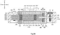
Fig. 2B is a sectional view of the vibration generator, taken alongline 2B-2B inFig. 1B . -
Fig. 2C is a sectional view of the vibration generator, taken alongline 2C-2C inFig. 1B . -
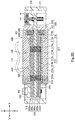
Fig. 2D is a sectional view, corresponding to a view taken alongline 2B-2B inFig. 1B , of another vibration generator including a plunger of another aspect. -
Fig. 3A is a front, top, right perspective exploded view of the vibration generator. -
Fig. 3B is a rear, bottom, left perspective exploded view of the vibration generator. -
Fig. 4A is a perspective view of an electronic device of an embodiment of the invention. -
Fig. 4B is a front view of the electronic device. -
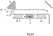
Fig. 4C is an end view of the electronic device. -
Fig. 5A is a plan view of an electronic device according to another embodiment of the invention. -
Fig. 5B is a side view of the electronic device. -
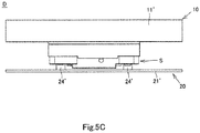
Fig. 5C is a front view of the electronic device. - In the brief description of the drawings above and the description of embodiments which follows, relative spatial terms such as "upper", "lower", "top", "bottom", "left", "right", "front", "rear", etc., are used for the convenience of the skilled reader and refer to the orientation of the vibration generators and their constituent parts as depicted in the drawings. No limitation is intended by use of these terms, either in use of the invention, during its manufacture, shipment, custody, or sale, or during assembly of its constituent parts or when incorporated into or combined with other apparatus.
- A vibration generator S according to an embodiment of the invention will now be described below with reference to
Figs. 1A to 3B . The vibration generator S includes acoil 100, aplunger 200, and aframe 300. The Y-Y' direction indicated inFigs. 1A to 2B and2D to 3B corresponds to the first direction recited in the claims. In the Y-Y' direction, the Y-direction corresponds to one side in the first direction, and the Y'-direction corresponds to the other side in the first direction. The X-X' direction indicated inFigs. 1A to 2A and2C to 3B corresponds to the second direction recited in the claims. The X-X' direction is orthogonal to the Y-Y' direction. The Z-Z' direction indicated inFigs. 1A ,1B , and2B to 3B corresponds to the third direction recited in the claims. The Z-Z' direction is orthogonal to the Y-Y' and X-X' directions. - The
coil 100 extends in the Y-Y' direction and is of a tuboid shape with a circular or polygonal section (generally rectangular section inFigs. 1A to 3B ). Thecoil 100 is connected to and energized via acable 110, a terminal (not shown), or a connector (not shown). - The
plunger 200 includes afirst shaft 210, which extends in the Y-Y' direction and is received in thecoil 100 such as to be movable in the Y-Y' direction. Thefirst shaft 210 may preferably be at least partly made of a magnetic material so as to be magnetically attractable to thecoil 100 and thereby movable in the Y-direction from its initial position. Thefirst shaft 210 may be in a shape of a circular cylinder, a polygonal prism, or the like extending in the Y-Y' direction. The initial position of thefirst shaft 210 of theplunger 200 is the position at which thefirst shaft 210 is located before elastic deformation of theframe 300. - The
first shaft 210 may include afirst portion 211 and asecond portion 212. Thefirst portion 211 is made of at least one member of a magnetic material and received in thecoil 100 such as to be movable in the Y-Y' direction. Thefirst portion 211 has a Y-direction end and a Y'-direction end. Thesecond portion 212 is made of a nonmagnetic material and extends in the Y-direction from Y-direction end of thefirst portion 211 to be located outside thecoil 100. - In the embodiment shown in
Figs. 2A to 2C ,3A , and3B , thefirst shaft 210 is configured as follows. Thefirst portion 211 of thefirst shaft 210 includes a plurality ofmagnetic plates 211a to 211e and a plurality ofpins 211f. Theplates 211a to 211e are stacked in this order in the Z-Z' direction and fixed together with thepins 211f. Thesecond portion 212 of thefirst shaft 210 includes abody 212a and anengagement projection 212b. Theengagement projection 212b is contiguous with the Y'-direction end of thebody 212a. Theengagement projection 212b is engaged with an engagement hole 211c1 of theplate 211c of thefirst portion 211 and held by and between theplates plates plates plate 211c, and theplates plate 211c. Thebody 212a extends in the Y-direction from the Y-direction end of thefirst portion 211 to be located outside thecoil 100. - The
first portion 211 of any aspect above may include only theplate 211c, or alternatively include theplate 211c and at least one magnetic plate fixed to theplate 211c. The plates of thefirst portion 211 of any aspect above may be fixed together with at least onepin 211f or other known fixing means, such as, at least one pin other than thepins 211f, at least one screw, an adhesive, and at least one adhesive tape. - The
first shaft 210 may include athird portion 213 and afourth portion 214, in place of thefirst portion 211 and thesecond portion 212. Thethird portion 213 may preferably be made of at least one member of a magnetic material and received in thecoil 100 such as to be movable in the Y-Y' direction. Thefourth portion 214 is made of a nonmagnetic material. Thefourth portion 214 includes abody 214a and anextension 214b. Thebody 214a is fixed to thethird portion 213. Theextension 214b extends in the Y-direction from thebody 214a to be located outside thecoil 100. - The
first shaft 210 of the embodiment shown inFig. 2D is configured as follows. Thethird portion 213 of thefirst shaft 210 includes a plurality ofmagnetic plates 213a to 213d and a plurality ofpins 213e. Theplates body 214a of thefourth portion 214 of thefirst shaft 210, and theplates body 214a. Thefourth portion 214 of thefirst shaft 210 has a plate shape. Thebody 214a of thefourth portion 214 is held by and between theplates plates body 214a and theplates 213a to 213d are fixed together with thepins 213e. Theextension 214b extends in the Y-direction from the Y-direction end of thethird portion 213 to be located outside thecoil 100. - The
third portion 213 of any aspect above may include theplate 213a and/or theplate 213c, or at least one magnetic plate fixed to the Z- or Z'-direction side face of thebody 214a of thefourth portion 214. The at least one plate of thethird portion 213 and thebody 214a of thefourth portion 214 of any aspect above may be fixed together with a known fixing means, such as at least onepin 213e, at least one pin other than thepins 213e, at least one screw, an adhesive, and/or at least one adhesive tape. - The
plunger 200 may further include asecond shaft 220. Thesecond shaft 220 may preferably extend in the X-X' direction, be disposed on the Y'-direction side relative to thecoil 100 with a gap therebetween, and be at least partly made of a magnetic material such as to be magnetically attractable to thecoil 100 and thereby movable in the Y-direction from its initial position. Thesecond shaft 220 may be integral with thefirst shaft 210 or may be a separate component attached to thefirst shaft 210. Thesecond shaft 220 may be in a shape of a circular cylinder, a polygonal prism, or the like extending in the X-X' direction. Thesecond shaft 220 is larger in X-X' direction dimension than thefirst shaft 210. Thesecond shaft 220 has a X-direction end portion and a X'-direction end portion (hereinafter referred to as opposite end portions). These opposite end portions of thesecond shaft 220 may preferably be disposed on the Y'-direction side relative to thecoil 100 with a gap therebetween. The initial position of thesecond shaft 220 of theplunger 200 is the position at which thesecond shaft 220 is located before elastic deformation of theframe 300. - In the embodiment shown in
Figs. 2A to 2C ,3A , and3B Figs. 2A to 2C ,3A , and3B , thesecond shaft 220 is configured as follows. Thesecond shaft 220 includes a plurality ofmagnetic plates 221a to 221 e. Theplates 221a to 221e are stacked in this order in the Z-Z' direction. Theplate 221a is connected integrally with theplate 211a. Theplate 221b is connected integrally with theplate 211b. Theplate 221c is connected integrally with theplate 211c. Theplate 221d is connected integrally with theplate 211d. Theplate 221e is connected integrally with theplate 211e. - In the embodiment shown in
Fig. 2D , thesecond shaft 220 is configured as follows. Thesecond shaft 220 includes a plurality ofmagnetic plates 222a to 222d and anonmagnetic plate 222e. Theplate 222a is connected integrally with theplate 213a. Theplate 222b is connected integrally with theplate 213b. Theplate 222c is connected integrally with theplate 213c. Theplate 222d is connected integrally with theplate 213d. Theplate 222e is connected integrally with thebody 214a of thefourth portion 214 of thefirst shaft 210. Theplates plate 222e, and theplates plate 222e. Theplate 222e is held by and between theplates plates - The
second shaft 220 of any aspect above may include at least one of the plurality of magnetic plates, or include theplate 222e and at least one magnetic plate fixed to the Z- or Z'-direction side face of theplate 222e. The plates of thesecond shaft 220 of any aspect above may be fixed together with a known fixing means, such as at least one pin, at least one screw, an adhesive, and/or at least one adhesive tape. - The
frame 300 may preferably be fixed to thefirst shaft 210 of theplunger 200 at a position on the Y-direction side relative to thecoil 100, fixed to thesecond shaft 220 of theplunger 200 at a position on the Y'-direction side relative to thecoil 100, and elastically deformable at least partly as a result of movement of the first andsecond shafts frame 300 may be made of an electrically and magnetically insulating resin or of metal. - The
frame 300 includes aframe body 310. Theframe body 310 surrounds thecoil 100 and theplunger 200. Theframe body 310 is configured to be elastically deformed at least partly when thecoil 100 is energized and the first andsecond shafts plunger 200 are magnetically attracted toward thecoil 100 to move from their initial positions. Theframe body 310 is configured to be restored when thecoil 100 is de-energized and stops magnetically attracting the first andsecond shafts plunger 200. When theframe body 310 is restored, the first andsecond shafts plunger 200 return to their initial positions. Repeated elastic deformation and restoration of theframe body 310 generate vibrations. The level, duration, frequency, etc. of vibrations can be adjusted by varying electrical parameters, e.g. voltage, frequency, or duty ratio, with respect to the energization of thecoil 100. Theframe body 310 may include an annular shape, a substantially U shape, a substantially V shape, a substantially L shape, or the like. - In the embodiment shown in
Figs. 1A to 3B , theframe body 310 is generally of rectangular loop shape including afirst portion 311, asecond portion 312, athird portion 313, and afourth portion 314. Thefirst portion 311 is spaced from and on the Y-direction side relative to theplunger 200. Thesecond portion 312 is spaced from and on the Y'-direction side relative to theplunger 200. Thethird portion 313 is located on the X-direction side relative to thecoil 100 and couples the X-direction end of thefirst portion 311 and the X-direction end of thesecond portion 312. Thefourth portion 314 is located on the X'-direction side relative to thecoil 100 and couples the X'-direction end of thefirst portion 311 and the X'-direction end of thesecond portion 312. - The
frame 300 further includes a firstfixable portion 320 and a secondfixable portion 330. The firstfixable portion 320 is provided at theframe body 310 such as to be located on the Y-direction side relative to thecoil 100. The firstfixable portion 320 is fixed to thefirst shaft 210 of theplunger 200 at a position on the Y-direction side relative to thecoil 100. The firstfixable portion 320 is fixed to thefirst shaft 210 with at least one screw or pin PI, an adhesive, at least one adhesive tape, or any other fixing means. The secondfixable portion 330 is provided at theframe body 310 such as to be located on the Y'-direction side relative to thecoil 100. The secondfixable portion 330 is fixed to thesecond shaft 220 of theplunger 200 at a position on the Y'-direction side relative to thecoil 100. The secondfixable portion 330 is fixed to thesecond shaft 220 with at least one screw or pin P2, an adhesive, at least one adhesive tape, or any other fixing means. - The at least one screw or pin P1 and the at least one screw or pin P2 may each include a head. A washer W may be interposed between the head of the or each screw or pin P1 and the first
fixable portion 320 and/or between the head of the or each screw or pin P2 and the secondfixable portion 330. The interposed washer or washers W serve to suppress disconnection of the at least one screw or pin P1 and/or P2 vibrating as a result of vibrations of theframe body 310. This reduces unintended disengagement of the firstfixable portion 320 from thefirst shaft 210 and/or of the secondfixable portion 330 from thesecond shaft 220. The or each washer W to be held by and between the head of the screw or pin P1 and the firstfixable portion 320 may include at least one tooth to dig into the firstfixable portion 320. The or each washer W to be held by and between the head of the screw or pin P2 and the secondfixable portion 330 may include at least one tooth to dig into the secondfixable portion 330. The or each washer W may specifically be a known toothed lock washer or star washer with a plurality of teeth along the inner or outer edge of the washer. In other words, the or each washer may have a plurality of teeth. The provision of the tooth or teeth on the at least one washer W further helps to prevent disconnection of the at least one screw or pin P1 and/or P2. For ease with which the tooth or teeth of the or each washer W can dig into with the firstfixable portion 320 and/or the secondfixable portion 330, theentire frame 300 or at least one of the firstfixable portion 320 and the secondfixable portion 330 may be made of plastic material as described above. The screw or pin P1 and/or the screw or pin P2 may have a body with a knurled pattern, which also helps to prevent disconnection of the at least one screw or pin P1 and/or P2. - The first
fixable portion 320 may be fixed to thefirst shaft 210 at a first position. The secondfixable portion 330 may be fixed to thesecond shaft 220 at a second position. The first position is at a first height position and on the Y-direction side relative to thecoil 100. The second position is at a second height position and on Y'-direction side relative to thecoil 100. The first and second height positions are different height positions in the Z-Z' direction. - In the embodiment shown in
Figs. 1A to 3B , the first and secondfixable portions fixable portion 320 is provided integrally with thefirst portion 311 of theframe body 310 and fixed to thefirst shaft 210 at a first position with a screw or pin P1. The secondfixable portion 330 is provided integrally with thesecond portion 312 of theframe body 310 and fixed to thesecond shaft 220 at a second position with two screws or pins P2. A star washer W with a plurality of teeth is interposed between the head of the screw or pin P1 and the firstfixable portion 320, with the teeth digging in the firstfixable portion 320. - The vibration generator S may further include an electrically and magnetically insulating
bobbin 400. Thebobbin 400 includes atrunk 410 and of a tuboid shape with a circular or polygonal section (generally rectangular section inFigs. 1A to 3B ). Thecoil 100 is wound aroundtrunk 410. Thefirst shaft 210 of theplunger 200 is received in thebobbin 400 and thecoil 100 such as to be movable in the Y-Y' direction. More specifically, thefirst portion 211 orthird portion 213 of thefirst shaft 210 may an outer size or diameter corresponding to the inner size or diameter of thebobbin 400, and thefirst portion 211 orthird portion 213 of thefirst shaft 210 may be disposed inside thebobbin 400 with a certain clearance therebetween so as to be movable in the Y-Y' direction. Thebobbin 400 may holds the terminal for connection with thecoil 100. Alternatively, thebobbin 400 may be provided integrally with or attached to the connector for connection with thecoil 100. - The vibration generator S may further include at least one
first yoke 510. Thefirst yoke 510 is made of soft iron or the like material that can enhance magnetic attraction force of thecoil 100. Thefirst yoke 510 is disposed between thesecond shaft 220 of theplunger 200 and thecoil 100. In this case, the opposite end portions of thesecond shaft 220 are disposed with a gap between themselves and thefirst yoke 510. Thefirst yoke 510 may be of a loop shape. Thefirst shaft 210 of theplunger 200 is received in thefirst yoke 510 such as to be movable in the Y-Y' direction. - In the embodiments shown in
Figs. 1A to 3B , the vibration generator S includes a plurality offirst yokes 510. Thefirst yokes 510 are loop-shaped plates disposed between thecoil 100 and the opposite end portions of thesecond shaft 220 of theplunger 200. Thefirst shaft 210 of theplunger 200 is received in thefirst yokes 510 such as to be movable in the Y-Y' direction. - The
bobbin 400 may further include afirst insulator 420. Thefirst insulator 420 is disposed between the at least onefirst yoke 510 and thecoil 100. Thefirst insulator 420 may be a loop-shaped flange along the Y'-direction end portion of thetrunk 410. Alternatively, thefirst insulator 420 may be a plurality of pieces radially extending from the Y'-direction end portion of thetrunk 410. Thefirst insulator 420 may or may not abut the first yokes 510. - In the embodiments shown in
Figs. 1A to 3B , thefirst insulator 420 is a loop-shaped flange along the Y'-direction end portion of thetrunk 410 and has a plurality ofsupports 421. Thefirst insulator 420 abuts thefirst yokes 510 from the Y-direction side. Thesupports 421 are received in thefirst yokes 510 to support the first yokes 510. - The vibration generator S may further include at least one
second yoke 520. Thesecond yoke 520 is made of soft iron or the like material that can enhance magnetic attraction force of thecoil 100. Thesecond yoke 520 is disposed on the Y-direction side relative to thecoil 100. Thesecond yoke 520 may be disposed on the Y-direction side relative to thecoil 100, with a gap between itself and thecoil 100 and between itself and the first orthird portion first shaft 210 of theplunger 200. Thesecond yoke 520 may be of a loop shape. In this case, thebody 212a of thesecond portion 212 or theextension 214b of thefourth portion 214 of thefirst shaft 210 of theplunger 200 is received in thesecond yoke 520 such as to be movable in the Y-Y' direction. - In the embodiments shown in
Figs. 1A to 3B , the vibration generator S includes a plurality ofsecond yokes 520 including a plurality of loop-shaped second yokes 521 and a loop-shapedsecond yoke 522. In the embodiment ofFigs. 2A and2B , thesecond yokes 521 and thesecond yoke 522 are disposed on the Y-direction side relative to thecoil 100 with gaps between themselves and thecoil 100 and between themselves and thefirst portion 211 of thefirst shaft 210 of theplunger 200. In the embodiment shown inFig. 2D , thesecond yokes 521 and thesecond yoke 522 are disposed on the Y-direction side relative to thecoil 100 with a gap between themselves and thecoil 100 and between themselves and thethird portion 213 of thefirst shaft 210 of theplunger 200. - The
bobbin 400 may further include asecond insulator 430. Thesecond insulator 430 is disposed between the at least onesecond yoke 520 and thecoil 100. Thesecond insulator 430 may be a loop-shaped flange along the Y-direction end portion of thetrunk 410. Alternatively, thesecond insulator 430 may be a plurality of pieces radially extending from the Y-direction end portion of thetrunk 410. Thesecond insulator 430 may or may not abut the second yokes 520. - In the embodiments shown in
Figs. 1A to 3B , thesecond insulator 430 is a loop-shaped flange along the Y-direction end portion of thetrunk 410. Thesecond insulator 430 has arecess 431 and a plurality ofsupports 432. Therecess 431 opens to the Y-direction side and accommodates the second yokes 521. Thesecond insulator 430 abuts thesecond yoke 522 from the Y'-direction side. Thesecond yoke 522 is in abutment from the Y-direction side with thesecond yokes 521 accommodated in therecess 431 of thesecond insulator 430. Thesupports 432 extends from the edge of therecess 431 and fit in thesecond yoke 522 to support thesecond yoke 522. - The vibration generator S may further include a
buffer 600. Thebuffer 600 is made of an elastic material, such as rubber or a plastic material, and interposed between the at least onefirst yoke 510 and thefirst insulator 420 and/or between the at least onesecond yoke 520 and thesecond insulator 430. In other words, thebuffer 600 is held by and between the at least onefirst yoke 510 and thefirst insulator 420 and/or between the at least onesecond yoke 520 and thesecond insulator 430. Thebuffer 600 serves to suppress noises generated by physical contact between the at least onefirst yoke 510 and thefirst insulator 420 and/or between the at least onesecond yoke 520 and thesecond insulator 430. Thebuffer 600 may loop-shaped. In this case, thesecond portion 212 or theextension 214b of thefourth portion 214 of thefirst shaft 210 of theplunger 200 is received in thebuffer 600 such as to be movable in the Y-Y' direction. Thebuffer 600 may be electrically conductive or insulative. - In the embodiments shown in
Figs. 2A to 3B , thebuffer 600 is a loop-shaped member of elastic material, accommodated in therecess 431 of thesecond insulator 430 together with thesecond yokes 521, and held by and between thesecond yokes 520 and thesecond insulator 430. - The vibration generator S may further include at least one
third yoke 530 and at least onefourth yoke 540. The third andfourth yokes coil 100. The third andfourth yokes coil 100. The at least onethird yoke 530 is disposed on the X-direction side relative to thecoil 100, and the at least onefourth yoke 540 is disposed on the X'-direction side relative to thecoil 100. The third andfourth yokes first insulator 420 and thesecond insulator 430. - The third and
fourth yokes fourth yokes first yoke 510 at positions on the Y'-direction side relative to thecoil 100. This coupling may specifically be such that the Y'-direction end portions of the third andfourth yokes first yoke 510, or such that the Y'-direction end portions of the third andfourth yokes first yoke 510, or such that the at least onefirst yoke 510 is provided with engagement projections to engage with the Y'-direction end portions of the third andfourth yokes fourth yokes second yoke 520 at positions on the Y-direction side relative to thecoil 100, in a similar manner to the coupling between the Y'-direction end portions of the third andfourth yokes first yoke 510. - The first, third, and
fourth yokes bobbin 400 in the X-X' direction. In other words, the first, third, andfourth yokes bobbin 400, and thecoil 100 may be combined in a single unit (hereinafter referred to as a unit 1 for convenience of description). In the unit 1, thebobbin 400 is held in the X-X' direction between the at least onethird yoke 530 and the at least onefourth yoke 540. At least one of the yokes of the unit 1 may be fixed to theframe 300. Alternatively, the second, third, andfourth yoke bobbin 400 in the X-X' direction. In other words, the second, third, andfourth yoke bobbin 400, and thecoil 100 may be combined in a single unit (hereinafter referred to as a unit 2 for convenience of description). In the unit 2, thebobbin 400 is held in the X-X' direction between the at least onethird yoke 530 and the at least onefourth yoke 540. At least one of the yokes in the unit 2 may be fixed to theframe 300. Alternatively, the first, second, third, andfourth yokes bobbin 400 in the X-X' direction and/or in the Y-Y' direction. In other words, the first, second, third, andfourth yokes bobbin 400, and thecoil 100 may be combined in a single unit (hereinafter referred to as a unit 3 for convenience of description). In the unit 3, thebobbin 400 is held in the Y-Y' direction between the at least onefirst yoke 510 and the at least onesecond yoke 520 and/or held in the X-X' direction between the at least onethird yoke 530 and the at least onefourth yoke 540. At least one of the yokes of the unit 3 may be fixed to theframe 300. - In the embodiments shown in
Figs. 1A to 3B , the third andfourth yokes fourth yokes second yoke 520 to form a generally U-shape. The X-direction end portions of the twofirst yokes 510 are formed with engagement projections (first engagement projections) in engagement with an engagement recess in the Y'-direction end portion of thethird yoke 530, and the X'-direction end portions of the twofirst yokes 510 are formed with engagement projections (second engagement projections) in engagement with an engagement recess in the Y'-direction end portion of thefourth yoke 540, so that thefirst yokes 510 are coupled to the Y'-direction end portions of the third andfourth yokes fourth yokes bobbin 400 in the Y-Y' direction and in the X-X' direction. Thethird yoke 530 is fixed to thethird portion 313 of theframe 300 with a screw. - The
frame 300 may further include apositioner 340. Thepositioner 340 is provided at theframe body 310 to retain the unit 1, 2, or 3 in position. Thepositioner 340 may includeretainers retainers third portion 313 and/or thefourth portion 314 of theframe body 310 to be spaced from each other in the Y-Y' direction and retain the unit 1, 2, or 3 in position in the Y-Y' direction. In the case where there is provided the unit 1 retained in position by theretainers retainer 341 abuts thebobbin 400 of the unit 1 from the Y-direction side, and theretainer 342 abuts the at least onefirst yokes 510 of the unit 1 from the Y'-direction side. In the case where there is provided the unit 2 retained in position by theretainers retainer 341 abuts the at least onesecond yoke 520 of the unit 2 from the Y-direction side, and theretainer 342 abuts thebobbin 400 of the unit 2 from the Y'-direction side. In the case where there is provided the unit 3 retained in position by theretainers retainer 341 abuts the at least onesecond yoke 520 of the unit 3 from the Y-direction side, and theretainer 342 abuts the at least onefirst yoke 510 of the unit 3 from the Y'-direction side. - The
positioner 340 may further includeretainers retainers third portion 313 and/or thefourth portion 314 of theframe body 310 to be spaced from each other in the Z-Z' direction and retrain the unit 1, 2, or 3 in position in the Z-Z' direction. In this case, theretainer 343 abuts the at least one third orfourth yoke retainer 344 abuts the at least one third orfourth yoke - In the embodiments shown in
Figs. 1A to 3B , thepositioner 340 includesretainers 341 to 344. Theretainers third portion 313 of theframe body 310 to be spaced from each other in the Y-Y' direction. Theretainer 341 abuts thesecond yoke 522 of the unit 3 from the Y-direction side, and theretainer 342 abuts thefirst yokes 510 of the unit 3 from the Y'-direction side. Theretainers third portion 313 of theframe body 310 to be spaced from each other in the Z-Z' direction. Theretainer 343 abuts thethird yoke 530 of the unit 3 from the Z-direction side, and theretainer 344 abuts thethird yoke 530 of the unit 3 from the Z'-direction side. Thepositioner 340 may be a recess or recesses configured to retain the unit 1, 2, or 3 in position in the Y-Y' direction and/or in the X-X' direction. - The
frame 300 may further include at least one thirdfixable portion 350 and at least one fourthfixable portion 360. The thirdfixable portion 350 is provided at theframe body 310 and configured to be fixed to afixable part 10 of an electronic device D (to be described). The fourthfixable portion 360 is provided at theframe body 310 and configured to fixed to a vibratable part 20 (to be described) of the electronic device D. The fourthfixable portion 360 may be coupled to at least one of the firstfixable portion 320 or the secondfixable portion 330 of theframe 300. - The at least one fourth
fixable portion 360 may be a pair of fourth fixable portions. In this case, one of the fourthfixable portions 360 is provided at theframe body 310 and configured to be fixed to thevibratable part 20 of the electronic device D at a position on the Y-direction side relative to the at least one thirdfixable portion 350. The other fourthfixable portion 360 is provided at theframe body 310 and configured to be fixed to thevibratable part 20 of the electronic device D at a position on the Y' side relative to the at least one thirdfixable portion 350. In other words, the at least one thirdfixable portion 350 is provided at theframe body 310 to be located between the pair of fourthfixable portions 360 in the Y-Y' direction. Owing to such arrangement of the at least one thirdfixable portion 350 and the pair of fourthfixable portions 360, vibrations generated at theframe body 310 are unlikely to travel to thefixable part 10 but easily travel to thevibratable part 20. The one of the fourthfixable portions 360 may be coupled to the firstfixable portion 320 of theframe 300. The other fourthfixable portion 360 may be coupled to the secondfixable portion 330 of theframe 300. - In the embodiments shown in
Figs. 1A to 3B , two thirdfixable portions 350 and twofourth portions 314. The thirdfixable portions 350 are contiguous plates, each with a screw hole, provided at thethird portion 313 of theframe body 310. The one of the fourthfixable portions 360 is a fixable plate with a screw hole, provided at the Y-direction end of thefourth portion 314 of theframe body 310. The other fourthfixable portion 360 is a fixable plate with a screw hole, provided at the Y'-direction end of thefourth portion 314 of theframe body 310. Theframe body 310 in its original configuration constitutes a generally rectangular linkage formed by the first, second, third andfourth portions plunger 200 is fixed relative to thefourth frame portion 314 by the screws or pins P1 and P2, while thecoil 100 is held by theretainers third frame portion 313. When thecoil 100 is energised, theplunger 200 moves in the Y direction relative to thecoil 100, and thus thefourth frame portion 314 moves with theplunger 200 in the Y direction relative to thethird frame portion 313. In this manner, theframe body 310 can be deformed into a generally parallelogram shape. The first andsecond frame portions second frame portions - The vibration generator S according to the aspects shown in
Figs. 1A to 3B may be assembled in the following steps. There are prepared thebobbin 400 with thecoil 100 wound therearound, thebuffer 600, and the twosecond yokes 521. Thebuffer 600 and thesecond yokes 521 are placed in this order into therecess 431 of thesecond insulator 430 of thebobbin 400. Subsequently prepared are thesecond yoke 522, thethird yoke 530, and thefourth yoke 540 as coupled together (hereinafter referred to as a U-yoke). Thesupports 432 of thesecond insulator 430 of thebobbin 400 are fitted into the hole in thesecond yoke 522 of the U-yoke, and thesecond yoke 522 is brought into abutment with thesecond insulator 430 and with thesecond yokes 521 inside therecess 431 of thesecond insulator 430. Also, thethird yoke 530 and thefourth yoke 540 of the U-yoke are respectively disposed on the X- and X'-direction sides relative to thebobbin 400 and thecoil 100. Accordingly, thethird yoke 530 abuts thefirst insulator 420 and thesecond insulator 430 of thebobbin 400 from the X-direction side, and thefourth yoke 540 abuts thefirst insulator 420 and thesecond insulator 430 from the X'-direction side. - Also prepared are the two
first yokes 510. The first engagement projections of thefirst yokes 510 are brought into engagement with the engagement recess of thethird yoke 530, and the second engagement projections of thefirst yokes 510 are brought into engagement with the engagement recess of thefourth yoke 540. Thefirst yokes 510 thus abuts thefirst insulator 420 of thebobbin 400 and couple between thethird yoke 530 and thefourth yoke 540 at a position on the Y'-direction side relative to thecoil 100. The first yokes 510, thesecond yoke 522, thethird yoke 530, thefourth yoke 540, and thebobbin 400 with thecoil 100 are combined into a single unit, i.e. the unit 3. - Subsequently prepared is the
plunger 200 in a T-plate shape. Theplunger 200 may be configured as shown inFigs. 2A to 2C or as shown inFig. 2D . Thefirst shaft 210 of theplunger 200 is inserted into thefirst yokes 510, thebobbin 400, thebuffer 600, thesecond yokes 521, and thesecond yoke 522. In theplunger 200 thus inserted, thesecond portion 212 or thefourth portion 214 of thefirst shaft 210 projects in the Y-direction out of thebobbin 400, thebuffer 600, thesecond yokes 521, and thesecond yoke 522, and thesecond shaft 220 is disposed on the Y'-direction side relative to thecoil 100 with a gap between itself and thesecond yoke 522. - The
frame 300 is also prepared. The unit 3 and theplunger 200 are placed inside theframe body 310 of theframe 300, so that thepositioner 340 of theframe 300 retains the unit 3 in position. Thethird yoke 530 of the unit 3 is then fixed to theframe 300 with a screw. Thesecond portion 212 or thefourth portion 214 of theplunger 200 is then fixed to the firstfixable portion 320 of theframe 300 with the screw or pin P1. The washer W, which is a star washer, is interposed between the firstfixable portion 320 and the screw or pin P1. Meanwhile, thesecond shaft 220 of theplunger 200 is fixed to the secondfixable portion 330 with the screws or pins P2. This is how the vibration generator S is assembled. - An electronic device D according to embodiments of the invention will now be described below with reference to
Figs. 4A to 5C . Examples of the electronic device D include car navigation systems for motor vehicles, information terminals (e.g. tablet computers, smartphones, handheld gaming devices, electronic dictionaries, personal computers, etc.), facsimile devices, printers, scanners, arcade game machines, guide boards, automated teller machines, and ticket machines. The electronic device D includes a touch sensing device (not shown), at least one vibration generator S of any aspect above, afixable part 10, and avibratable part 20. In the embodiment shown inFigs. 4A to 4C , three vibration generators S are provided. In the embodiment shown inFigs. 5A to 5C , one vibration generator S is provided. - The
vibratable part 20 is connected to theframe 300 of the vibration generator S and configured to be vibrated as a result of repeated elastic deformation and restoration of theframe 300. Thevibratable part 20 at least includes a vibratable plate and the touch sensing device. The touch sensing device is fixed directly or indirectly to the vibratable plate. Vibrations generated by the vibration generator S travel to the touch sensing device via the vibratable plate. The vibrations in the touch sensing device can be felt by a user touching the touch sensing device, and the user recognize the vibrations as tactile acknowledgements of the touch action on the touch sensing device. -
Figs. 4A to 4C show an example of thevibratable part 20. Thevibratable part 20 includes avibratable plate 21, asupport frame 22, and the touch sensing device. Thevibratable plate 21 is disposed on one side (hereinafter referred to as the upper side for convenience of description) of the three vibration generators S in an opposed manner. Thevibratable plate 21 is fixed to the pair of fourthfixable portions 360 of theframe 300 of each of the three vibration generators S via spacers (not shown) interposed therebetween. Thesupport frame 22 is fixed to thevibratable plate 21 via a plurality ofspacers 23 interposed therebetween and located on the upper side of thevibratable plate 21. The touch sensing device is attached to and supported by thesupport frame 22. Vibrations generated by the vibration generators S travel to the touch sensing device via thevibratable plate 21 and thesupport frame 22. -
Figs. 5A to 5C show another example of thevibratable part 20. Thevibratable part 20 includes a vibratable plate 21' and the touch sensing device. The vibratable plate 21' is disposed on one side of the vibration generator S in an opposed manner and fixed to the pair of fourthfixable portions 360 of theframe 300 of the vibration generator S via a spacer 24' interposed therebetween. The touch sensing device is fixed directly or indirectly to the vibratable plate 21'. Vibration generated by the vibration generator S travel to the touch sensing device via the vibratable plate 21'. - The
fixable part 10 is fixed to theframe 300 of the or each vibration generator S. Thefixable part 10 may include a fixable plate. The fixable plate is fixed directly or indirectly to at least one of the thirdfixable portions 350 of theframe 300 of the or each vibration generator S and fixed directly or indirectly to a frame, a body, or other part of the electronic device. -
Figs. 4A to 4C show an example of thefixable part 10. Thefixable part 10 includes afixable plate 11. Thefixable plate 11 is disposed on the other side (hereinafter referred to as the lower side for convenience of description) of the three vibration generators S in an opposed manner. Thefixable part 10 is fixed directly to the two thirdfixable portions 350 of theframe 300 of each of the three vibration generators S. A plurality ofspacers 40 is interposed between thefixable plate 11 and thevibratable plate 21. -
Figs. 5A to 5C show another example of thefixable part 10. Thefixable part 10 includes a fixable plate 11'. The fixable plate 11' is fixed directly to the two thirdfixable portions 350 of theframe 300 of the vibration generator S and extends in a direction to be separated from the vibration generator S. - The electronic device D may further include a
circuit board 50. Thecircuit board 50 is connected to the at least one vibration generator S and the touch sensing device. In the embodiment shown inFigs. 4A to 4C , thecircuit board 50 is disposed between thevibratable plate 21 and thesupport frame 22 and fixed to thefixable plate 11 via aspacer 60 interposed therebetween. Thecircuit board 50 is not shown inFigs. 5A to 5C for convenience of illustration. - The vibration generator S and the electronic device D configured as described above has at least the following technical features. Firstly, the
coil 100 provides enhanced magnetic attraction force applied to theplunger 200 for the following reasons (1) to (4). (1) Thecoil 100 magnetically attracts thesecond shaft 220 as well as thefirst shaft 210 of theplunger 200. Thefirst shaft 210 of theplunger 200 is inserted in thebobbin 400 to lower the magnetic resistance of thefirst shaft 210. This enhances the magnetic attraction force of thecoil 100 applied to thefirst shaft 210. (2) In the case where the vibration generator S includes the at least onefirst yoke 510, the at least onefirst yoke 510 is interposed between thecoil 100 and thesecond shaft 220 of theplunger 200. The existence of the at least onefirst yoke 510 enhances magnetic attraction force of thecoil 100 applied to thesecond shaft 220. (3) In the case where the vibration generator S includes the at least onesecond yoke 520, the at least onesecond yoke 520 is disposed with a gap between itself and thecoil 100 and between itself and the first orthird portion plunger 200. This arrangement enhances the magnetic attraction force of thecoil 100 applied to thefirst shaft 210. (4) In the case where the vibration generator S includes thethird yoke 530 and thefourth yoke 540, thethird yoke 530 extends in the Y-Y' direction on the X-direction side relative to thecoil 100, thefourth yoke 540 extends in the Y-Y' direction on the X'-direction side relative to thecoil 100. The existence of thethird yoke 530 and thefourth yoke 540 also enhances magnetic attraction force of thecoil 100 applied to theplunger 200. - Secondly, the vibration generator S is easy to assemble especially in the case where the
bobbin 400 is retained by the first, third,fourth yokes fourth yokes fourth yokes bobbin 400 form a unitized combination of the yokes, thebobbin 400, and thecoil 100. The unit, namely the unit 1, 2, or 3, can be fixed to theframe 300 easily by fixing at least one of the coupled yokes to theframe 300. - Thirdly, in the case where the
first shaft 210 of theplunger 200 is fixed to the firstfixable portion 320 of theframe 300 at the first position while thesecond shaft 220 of theplunger 200 is fixed to the secondfixable portion 330 of theframe 300 at the second position, such arrangements make it easier to elastically deform theframe 300 as a result of movements of theplunger 200. This is because setting the first and second positions at different heights makes it easier to warp theframe body 310 of theframe 300 as a result of movements of theplunger 200. - Fourthly, the vibration generator S, if having any of the following configurations (1) or (2), suppresses disconnection of the screws or pins PI, P2. (1) The screws or pins PI, P2 have knurled patterns. (2) The head of the screw or pin P1 and the first
fixable portion 320 of theframe 300 holds the washer W therebetween and at least one tooth of the washer W digs into the firstfixable portion 320, and/or the head of the or each screw or pin P2 and the secondfixable portion 330 of theframe 300 holds the washer W therebetween and at least one tooth of the washer W digs into the secondfixable portion 330. - It should be appreciated that the vibration generator and the electronic device described above are not limited to the above embodiments but can be modified in any manner within the scope of the claims. Specific modifications will be described in detail below.
- The vibration generator of the invention may further include a biasing part of an elastic material, such as a coil spring and a rubber member. This biasing part may be interposed between a first abuttable part and a second abuttable part to bias the plunger in the direction of restoration movement, i.e. to the other side in the first direction. The first abuttable part may preferably be a part of the first shaft of the plunger that projects from the coil and/or the bobbin. In this case, the first shaft may preferably be fixed to the frame at a position on the one side in the first direction relative to the first abuttable part. The second abuttable part may preferably be a part of the bobbin, a part of the coil, or a part of the at least one second yoke. The biasing part may be of a tuboid shape. In this case, the biasing part may receive therein the part of the first shaft of the plunger that projects from the coil and/or the bobbin.
- The vibration generator of the invention may not include any of the second shaft of the plunger, the bobbin, and/or the first, second, third, and/or fourth yoke.
- The vibration generator of the invention is applicable also to an electronic device including no touch sensing device. Such an electronic device may preferably include a part configured to be vibrated as a result of vibrations generated by the vibration generator of the invention.
- It should be appreciated that the above embodiments and variants of the vibration generator and the electronic device are described above by way of examples only. The materials, shapes, dimensions, numbers, arrangements, and other configurations of the constituents of the multilayer printed wiring board and the connection structure may be modified in any manner if they can perform similar functions. The configurations of the embodiments and the variants described above may be combined in any possible manner. The first direction may be any direction of movement and restoration of the plunger of any aspect above. The second direction may be any direction orthogonal to the first direction. The third direction may be any direction crossing the first and second directions.
-
- S:
- Vibration generator
100: Coil
200: Plunger
210: First shaft
211: First portion
211a: Plate
211b: Plate
211c: Plate
211c1: Engagement hole
211d: Plate
211e: Plate
211f: Pin
212: Second portion
212a: Body
212b: Engagement projection
213: Third portion
213a: Plate
213b: Plate
213c: Plate
213d: Plate
213e: Pin
214: Fourth portion
214a: Body
214b: Extension
220: Second shaft
221a: Plate
221b: Plate
221c: Plate
221d: Plate
221e: Plate
222a: Plate
222b: Plate
222c: Plate
222d: Plate
222e: Plate
300: Frame
310: Frame body
311: First portion
312: Second portion
313: Third portion
314: Fourth portion
320: First fixable portion
330: Second fixable portion
340: Positioner
341: Retainer
342: Retainer
350: Third fixable portion
360: Fourth fixable portion
400: Bobbin
410: Trunk
420: First insulator
430: Second insulator
431: Recess
510: First yoke
520: Second yoke
521: Second yoke
522: Second yoke
530: Third yoke
540: Fourth yoke
600: Buffer
P1: Screw or pin
P2: Screw or pin
W: Washer - D:
- Electronic device
10: Fixable part
11: Fixable plate
20: Vibratable part
21: Vibratable plate
22: Support frame
23: Spacer
40: Spacer
50: Substrate
60: Spacer - D:
- Electronic device
10: Fixable part
11': Fixable plate
20: Vibratable part
21': Vibratable plate
24': Spacer.
Claims (10)
- A vibration generator (S) comprising:a frame (300) including a first fixable portion (320), a second fixable portion (330), and a third portion (313);a coil (100) fixed to the third portion (313) of the frame (300);the first fixable portion (320) being located on one side (Y) in a first direction (Y-Y') relative to the coil (100);the second fixable portion (330) being located on an other side (Y') in the first direction (Y-Y') relative to the coil (100);the third portion (313) being located on the one side (X) in a second direction (X-X') relative to the coil (100), the second direction (X-X') being orthogonal to the first direction (Y-Y');a plunger (200) movable relative to the coil in the first direction (Y-Y');at least one yoke (520, 521, 522) disposed on the one side (Y) in the first direction (Y-Y') relative to the coil (100);a yoke (530) disposed on the one side (X) in the second direction (X-X') relative to the coil (100) and extending in the first direction (Y-Y'); anda yoke (540) disposed on the other side (X') in the second direction (X-X') relative to the coil (100) and extending in the first direction (Y-Y');a bobbin (400) having a tuboid shape and an insulation property, wherein the coil (100) is wound around the bobbin, wherein the plunger includes:a first shaft (210) received in the coil and at least partly made of a magnetic material and movable to the one side (Y) in the first direction (Y-Y')
when the coil (100) is energised, anda second shaft (220) extending from the first shaft (210) in the second direction (X-X'), being disposed on the other side (Y') in the first direction (Y-Y') relative to the coil with a gap therebetween, and being at least partly made of a magnetic material and movable to the one side (Y) in the first direction when the coil (100) is energised; andthe first shaft (210) is fixed to the first fixable portion (320) of the frame (300) at a position on the one side (Y) in the first direction relative to the coil (100), andthe second shaft (220) is fixed to the second fixable portion (330) of the frame (300) at a position on the other side (Y') in the first direction relative to the coil (100), andthe frame (300) is elastically deformable at least partly as a result of movement of the first and second shafts relative to the coil such that the first and second fixable portions (320, 330) of the frame (300) are movable relative to the third portion (313) in the first direction (Y-Y');the first shaft (210) of the plunger (200) includes:a first portion (211) of a magnetic material received in the coil (100), anda second portion (212) of a nonmagnetic material extending from the first portion (211) to the one side (Y) in the first direction (Y-Y') to be located outside the coil (100),there is a gap between the at least one yoke (520, 521, 522) disposed on the one side (Y) in the first direction (Y-Y') relative to the coil (100) and the coil, and a gap between the at least one yoke (520, 521, 522) disposed on the one side (Y) in the first direction (Y-Y') relative to the coil (100) and the first portion (211) of the plunger (200),the at least one yoke (520, 521, 522) disposed on the one side (Y) in the first direction (Y-Y') relative to the coil (100) couples the yoke (530) disposed on the one side (X)
in the second direction (X-X') relative to the coil (100) and the yoke (540) disposed on the other side (X') in the second direction (X-X') relative to the coil (100) at a position on the one side (Y) in the first direction relative to the coil (100),the yokes (520, 521, 522; 530; 540) hold the bobbin (400), andat least one of the yokes (520, 521, 522; 530; 540) is fixed to the third portion (313) of the frame (300). - A vibration generator (S) comprising:a frame (300) including a first fixable portion (320), a second fixable portion (330), and a third portion (313);a coil (100) fixed to the third portion (313) of the frame (300);the first fixable portion (320) being located on one side (Y) in a first direction (Y-Y') relative to the coil (100);the second fixable portion (330) being located on an other side (Y') in the first direction (Y-Y') relative to the coil (100);the third portion (313) being located on the one side (X) in a second direction (X-X') relative to the coil (100), the second direction (X-X') being orthogonal to the first direction (Y-Y');a plunger (200) movable relative to the coil in the first direction (Y-Y');at least one yoke (520, 521, 522) disposed on the one side (Y) in the first direction (Y-Y') relative to the coil (100);a yoke (530) disposed on the one side (X) in the second direction (X-X') relative to the coil (100) and extending in the first direction (Y-Y'); anda yoke (540) disposed on the other side (X') in the second direction(X-X') relative to the coil (100) and extending in the first direction (Y-Y');a bobbin (400) having a tuboid shape and an insulation property, wherein the coil (100) is wound around the bobbin,
wherein the plunger includes:a first shaft (210) received in the coil and at least partly made of a magnetic material and movable to the one side (Y) in the first direction (Y-Y')
when the coil (100) is energised, anda second shaft (220) extending from the first shaft (210) in the second direction (X-X'), being disposed on the other side (Y') in the first direction (Y-Y') relative to the coil with a gap therebetween, and being at least partly made of a magnetic material and movable to the one side (Y) in the first direction when the coil (100) is energised; andthe first shaft (210) is fixed to the first fixable portion (320) of the frame (300) at a position on the one side (Y) in the first direction relative to the coil (100), andthe second shaft (220) is fixed to the second fixable portion (330) of the frame (300) at a position on the other side (Y') in the first direction relative to the coil (100), andthe frame (300) is elastically deformable at least partly as a result of movement of the first and second shafts relative to the coil such that the first and second fixable portions (320, 330) of the frame (300) are movable relative to the third portion (313) in the first direction (Y-Y'),the first shaft (210) of the plunger (200) includes:a third portion (213) of a magnetic material received in the coil (100), anda fourth portion (214) of a nonmagnetic material including:a body (214a) fixed to the third portion (213) and located inside the coil (100), andan extension (214b) extending from the body (214a) to the one side (Y) in the first direction (Y-Y') to be located outside the coil (100),there is a gap between the at least one yoke (520, 521, 522) disposed on the one side (Y) in the first direction (Y-Y') relative to the coil (100) and the coil, and a gap between the least one yoke (520, 521, 522) disposed on the one side (Y) in the first direction (Y-Y') relative to the coil (100) and the third portion (213) of the plunger (200),the at least one yoke (520, 521, 522) disposed on the one side (Y) in the first direction (Y-Y') relative to the coil (100) couples the yoke (530) disposed on the one side (X)
in the second direction (X-X') relative to the coil (100) and the yoke (540) disposed on the other side (X') in the second direction(X-X') relative to the coil (100) at a position on the one side (Y) in the first direction relative to the coil (100),the yokes (520, 521, 522; 530; 540) hold the bobbin (400), andat least one of the yokes (520, 521, 522; 530; 540) is fixed to the third portion (313) of the frame (300). - The vibration generator (S) according to claim 1 or claim 2, further comprising at least one yoke (510) disposed between the second shaft (220) of the plunger (200) and the coil (100),
and there is a gap between the second shaft (220) and the at least one yoke (510) disposed between the second shaft (220) of the plunger (200) and the coil (100). - The vibration generator (S) according to claim 3, wherein the yoke (510) disposed between the second shaft (220) of the plunger (200) and the coil (100) couples between the yoke (530) disposed on one side (X) in the second direction (X-X') relative to the coil (100) and the yoke (540) disposed on the other side (X') in the second direction (X-X') relative to the coil (100) at a position on the other side (Y') in the first direction relative to the coil.
- The vibration generator (S) according to any one of the preceding claims, wherein the bobbin includes:a trunk (410) with the coil (100) wound therearound, anda second insulator (430) between the yoke (520, 521, 522) disposed on the one side (Y) in the first direction (Y-Y') relative to the coil (100) and the coil (100),wherein the first shaft (210) of the plunger (200) is received in the coil (100) and the trunk (410) of the bobbin (400).
- The vibration generator (S) according to claim 5, further comprising a buffer (600) held by and between the yoke (520, 521, 522) disposed on the one side (Y) in the first direction (Y-Y') relative to the coil (100) and the second insulator (430).
- The vibration generator (S) according to claim 4, wherein
the coil (100) is wound around the bobbin,
the yoke (510) disposed between the second shaft (220) of the plunger (200) and the coil (100), the yoke (530) disposed on one side (X) in the second direction (X-X') relative to the coil (100), and the yoke (540) disposed on the other side (X') in the second direction (X-X') relative to the coil (100) hold the bobbin (400), and
at least one of the yokes (510; 530; 540) is fixed to the third portion (313) of the frame (300). - The vibration generator (S) according to any one of the preceding claims, wherein
the first fixable portion (320) is fixed to the first shaft (210) at a first position, the first position being at a first position in a third direction (Z-Z'), and on the one side (Y) in the first direction (Y-Y') relative to the coil (100),
the second fixable portion (330) is fixed to the second shaft (220) at a second position, the second position being at a second position in a third direction (Z-Z'), and on the other side (Y') in the first direction (Y-Y'), relative to the coil (100),
the first position and the second position are different in the third direction (Z-Z'), and
the third direction (Z-Z') crosses the first direction (Y-Y') and the second direction (X-X'). - A vibration generator (S) according to any one of the preceding claims, wherein
the third portion (313) of the frame (300) of the vibration generator (S) includes a third fixable portion (350) for fixing the third portion (313) of the frame (300) to an electronic device, and
the frame (300) further includes a pair of fourth fixable portions (360) provided at positions on the one (Y) and other (Y') sides in the first direction (Y-Y') relative to the third fixable portion. - An electronic device (D) comprising:the vibration generator (S) according to claim 9;a fixable portion (10) fixed relative to the third portion (313) of the frame (300) of the vibration generator; anda vibratable member (20) connected to the fourth fixable portions (360) of the frame of the vibration generator and configured to be vibrated relative to the fixable portion (10) as a result of repeated elastic deformation and restoration of the frame.
Applications Claiming Priority (1)
| Application Number | Priority Date | Filing Date | Title |
|---|---|---|---|
| JP2015167623A JP6462533B2 (en) | 2015-08-27 | 2015-08-27 | Vibration generating apparatus and electronic apparatus equipped with the same |
Publications (2)
| Publication Number | Publication Date |
|---|---|
| EP3136573A1 EP3136573A1 (en) | 2017-03-01 |
| EP3136573B1 true EP3136573B1 (en) | 2019-12-04 |
Family
ID=56985425
Family Applications (1)
| Application Number | Title | Priority Date | Filing Date |
|---|---|---|---|
| EP16020298.2A Active EP3136573B1 (en) | 2015-08-27 | 2016-08-09 | Vibration generator and electronic device having the same |
Country Status (4)
| Country | Link |
|---|---|
| US (1) | US10263501B2 (en) |
| EP (1) | EP3136573B1 (en) |
| JP (1) | JP6462533B2 (en) |
| CN (1) | CN106487194B (en) |
Families Citing this family (8)
| Publication number | Priority date | Publication date | Assignee | Title |
|---|---|---|---|---|
| JP2018196255A (en) * | 2017-05-18 | 2018-12-06 | アルパイン株式会社 | Vibration generator and input device with vibration mechanism |
| CN110800199B (en) * | 2017-06-30 | 2022-07-26 | 日本电产三协株式会社 | Actuator |
| JP2019180149A (en) * | 2018-03-30 | 2019-10-17 | 日本電産サンキョー株式会社 | Actuator |
| WO2020105742A1 (en) * | 2018-11-19 | 2020-05-28 | 엘지전자 주식회사 | Display device for vehicle |
| CN113659793A (en) * | 2020-05-12 | 2021-11-16 | 星电株式会社 | Electromagnetic actuator and vibration generator including the same |
| JP7637559B2 (en) * | 2021-04-28 | 2025-02-28 | フォルシアクラリオン・エレクトロニクス株式会社 | Input Devices |
| CN114030478A (en) * | 2021-12-07 | 2022-02-11 | 蔚来汽车科技(安徽)有限公司 | Excitation device, vibration feedback device of interactive surface, vehicle-mounted equipment and vehicle |
| DE102022209133A1 (en) * | 2022-09-02 | 2024-03-07 | Aktiebolaget Skf | Sensor module for detecting the vibration behavior of a component without measuring the natural frequencies of the sensor module |
Family Cites Families (16)
| Publication number | Priority date | Publication date | Assignee | Title |
|---|---|---|---|---|
| GB501957A (en) * | 1937-06-19 | 1939-03-08 | Clipshave Inc | Improvements in vibratory electric motor apparatus |
| US2149126A (en) * | 1938-04-13 | 1939-02-28 | Spencer Millard Cole | Oscillatory motor |
| GB797649A (en) * | 1956-07-06 | 1958-07-09 | Schick Inc | Vibrator motor |
| JPH11135321A (en) * | 1997-10-29 | 1999-05-21 | Matsushita Electric Works Ltd | Electromagnetic solenoid |
| JP2001178104A (en) * | 1999-12-21 | 2001-06-29 | Konno Kogyosho:Kk | Compact solenoid plunger |
| JP2001218440A (en) * | 2000-02-02 | 2001-08-10 | Omron Corp | Linear solenoid |
| GB2393586B (en) * | 2002-09-27 | 2005-12-21 | Automotive Motion Tech Ltd | An electric motor |
| US7825903B2 (en) * | 2005-05-12 | 2010-11-02 | Immersion Corporation | Method and apparatus for providing haptic effects to a touch panel |
| JP2007281192A (en) * | 2006-04-06 | 2007-10-25 | Shinano Kenshi Co Ltd | Solenoid and pump using this |
| JP4319213B2 (en) * | 2006-10-16 | 2009-08-26 | アルプス電気株式会社 | Vibration generator |
| KR100909426B1 (en) * | 2006-10-17 | 2009-07-24 | 엘에스산전 주식회사 | Actuator |
| US8072317B2 (en) * | 2008-07-16 | 2011-12-06 | Johnson Electric S.A. | Haptic solenoid system |
| JP5677657B2 (en) * | 2011-03-31 | 2015-02-25 | 日本電産コパル株式会社 | Vibration actuator |
| GB2506922A (en) * | 2012-10-15 | 2014-04-16 | Nissan Motor Mfg Uk Ltd | Magnetic core location in a rotor assembly |
| US9436341B2 (en) * | 2012-12-21 | 2016-09-06 | Johnson Electric S.A. | Haptic feedback devices |
| JP6023691B2 (en) * | 2013-11-18 | 2016-11-09 | 日本電産コパル株式会社 | Vibration actuator |
-
2015
- 2015-08-27 JP JP2015167623A patent/JP6462533B2/en active Active
-
2016
- 2016-08-09 US US15/232,247 patent/US10263501B2/en active Active
- 2016-08-09 EP EP16020298.2A patent/EP3136573B1/en active Active
- 2016-08-25 CN CN201610726779.4A patent/CN106487194B/en active Active
Non-Patent Citations (1)
| Title |
|---|
| None * |
Also Published As
| Publication number | Publication date |
|---|---|
| JP2017046471A (en) | 2017-03-02 |
| JP6462533B2 (en) | 2019-01-30 |
| CN106487194A (en) | 2017-03-08 |
| CN106487194B (en) | 2020-04-24 |
| US10263501B2 (en) | 2019-04-16 |
| US20170063212A1 (en) | 2017-03-02 |
| EP3136573A1 (en) | 2017-03-01 |
Similar Documents
| Publication | Publication Date | Title |
|---|---|---|
| US10263501B2 (en) | Vibration generator and electronic device having the same | |
| US10432074B2 (en) | Vibrator unit and vibration generator | |
| JP5765588B2 (en) | Force feedback type touch panel device | |
| CN106067719B (en) | generator switch | |
| KR100536816B1 (en) | Magnetic actuator with reduced magnetic flux leakage | |
| CN114647307B (en) | Tactile feedback mechanism | |
| US20100213773A1 (en) | Linear Vibrator | |
| JP6427277B2 (en) | Vibration generating device and operation feeling providing type input device using the vibration generating device | |
| CN104508596A (en) | Haptic actuator | |
| JP6526196B2 (en) | Operation touch input device | |
| JP7646709B2 (en) | Load Detector | |
| JP7742251B2 (en) | Actuator | |
| CN103885581A (en) | Haptic Feedback Devices | |
| JP7581590B2 (en) | Tactile feedback device | |
| JP2022170145A (en) | actuator | |
| JP2022170144A (en) | actuator | |
| KR20140029630A (en) | Touch motion switch | |
| CN109074984A (en) | Electromagnetic feedback actuator for operating elements and device with at least one electromagnetic feedback actuator | |
| CN111527579A (en) | Electromagnetic relay | |
| WO2023210824A1 (en) | Vibration actuator and touch input device | |
| KR20180136915A (en) | Information output apparatus | |
| JP2023009795A (en) | actuator | |
| JP7798495B2 (en) | Actuator | |
| CN114189122B (en) | Vibration device and electronic apparatus | |
| US11592868B2 (en) | Push switch including vibrator |
Legal Events
| Date | Code | Title | Description |
|---|---|---|---|
| PUAI | Public reference made under article 153(3) epc to a published international application that has entered the european phase |
Free format text: ORIGINAL CODE: 0009012 |
|
| STAA | Information on the status of an ep patent application or granted ep patent |
Free format text: STATUS: THE APPLICATION HAS BEEN PUBLISHED |
|
| AK | Designated contracting states |
Kind code of ref document: A1 Designated state(s): AL AT BE BG CH CY CZ DE DK EE ES FI FR GB GR HR HU IE IS IT LI LT LU LV MC MK MT NL NO PL PT RO RS SE SI SK SM TR |
|
| AX | Request for extension of the european patent |
Extension state: BA ME |
|
| STAA | Information on the status of an ep patent application or granted ep patent |
Free format text: STATUS: REQUEST FOR EXAMINATION WAS MADE |
|
| STAA | Information on the status of an ep patent application or granted ep patent |
Free format text: STATUS: EXAMINATION IS IN PROGRESS |
|
| 17P | Request for examination filed |
Effective date: 20170821 |
|
| RBV | Designated contracting states (corrected) |
Designated state(s): AL AT BE BG CH CY CZ DE DK EE ES FI FR GB GR HR HU IE IS IT LI LT LU LV MC MK MT NL NO PL PT RO RS SE SI SK SM TR |
|
| 17Q | First examination report despatched |
Effective date: 20170926 |
|
| RIC1 | Information provided on ipc code assigned before grant |
Ipc: H02K 33/04 20060101AFI20190306BHEP Ipc: H02K 1/34 20060101ALI20190306BHEP Ipc: B06B 1/04 20060101ALI20190306BHEP Ipc: H02K 5/04 20060101ALN20190306BHEP Ipc: H02K 1/12 20060101ALN20190306BHEP |
|
| GRAP | Despatch of communication of intention to grant a patent |
Free format text: ORIGINAL CODE: EPIDOSNIGR1 |
|
| STAA | Information on the status of an ep patent application or granted ep patent |
Free format text: STATUS: GRANT OF PATENT IS INTENDED |
|
| INTG | Intention to grant announced |
Effective date: 20190423 |
|
| RIC1 | Information provided on ipc code assigned before grant |
Ipc: H02K 33/04 20060101AFI20190408BHEP Ipc: H02K 5/04 20060101ALN20190408BHEP Ipc: H02K 1/34 20060101ALI20190408BHEP Ipc: H02K 1/12 20060101ALN20190408BHEP Ipc: B06B 1/04 20060101ALI20190408BHEP |
|
| GRAJ | Information related to disapproval of communication of intention to grant by the applicant or resumption of examination proceedings by the epo deleted |
Free format text: ORIGINAL CODE: EPIDOSDIGR1 |
|
| STAA | Information on the status of an ep patent application or granted ep patent |
Free format text: STATUS: EXAMINATION IS IN PROGRESS |
|
| GRAP | Despatch of communication of intention to grant a patent |
Free format text: ORIGINAL CODE: EPIDOSNIGR1 |
|
| STAA | Information on the status of an ep patent application or granted ep patent |
Free format text: STATUS: GRANT OF PATENT IS INTENDED |
|
| INTC | Intention to grant announced (deleted) | ||
| INTG | Intention to grant announced |
Effective date: 20190628 |
|
| RIC1 | Information provided on ipc code assigned before grant |
Ipc: B06B 1/04 20060101ALI20190617BHEP Ipc: H02K 33/04 20060101AFI20190617BHEP Ipc: H02K 1/12 20060101ALN20190617BHEP Ipc: H02K 5/04 20060101ALN20190617BHEP Ipc: H02K 1/34 20060101ALI20190617BHEP |
|
| GRAS | Grant fee paid |
Free format text: ORIGINAL CODE: EPIDOSNIGR3 |
|
| GRAA | (expected) grant |
Free format text: ORIGINAL CODE: 0009210 |
|
| STAA | Information on the status of an ep patent application or granted ep patent |
Free format text: STATUS: THE PATENT HAS BEEN GRANTED |
|
| AK | Designated contracting states |
Kind code of ref document: B1 Designated state(s): AL AT BE BG CH CY CZ DE DK EE ES FI FR GB GR HR HU IE IS IT LI LT LU LV MC MK MT NL NO PL PT RO RS SE SI SK SM TR |
|
| REG | Reference to a national code |
Ref country code: GB Ref legal event code: FG4D |
|
| REG | Reference to a national code |
Ref country code: CH Ref legal event code: EP |
|
| REG | Reference to a national code |
Ref country code: AT Ref legal event code: REF Ref document number: 1210669 Country of ref document: AT Kind code of ref document: T Effective date: 20191215 |
|
| REG | Reference to a national code |
Ref country code: DE Ref legal event code: R096 Ref document number: 602016025335 Country of ref document: DE |
|
| REG | Reference to a national code |
Ref country code: IE Ref legal event code: FG4D |
|
| REG | Reference to a national code |
Ref country code: NL Ref legal event code: MP Effective date: 20191204 |
|
| REG | Reference to a national code |
Ref country code: LT Ref legal event code: MG4D |
|
| PG25 | Lapsed in a contracting state [announced via postgrant information from national office to epo] |
Ref country code: LV Free format text: LAPSE BECAUSE OF FAILURE TO SUBMIT A TRANSLATION OF THE DESCRIPTION OR TO PAY THE FEE WITHIN THE PRESCRIBED TIME-LIMIT Effective date: 20191204 Ref country code: SE Free format text: LAPSE BECAUSE OF FAILURE TO SUBMIT A TRANSLATION OF THE DESCRIPTION OR TO PAY THE FEE WITHIN THE PRESCRIBED TIME-LIMIT Effective date: 20191204 Ref country code: FI Free format text: LAPSE BECAUSE OF FAILURE TO SUBMIT A TRANSLATION OF THE DESCRIPTION OR TO PAY THE FEE WITHIN THE PRESCRIBED TIME-LIMIT Effective date: 20191204 Ref country code: BG Free format text: LAPSE BECAUSE OF FAILURE TO SUBMIT A TRANSLATION OF THE DESCRIPTION OR TO PAY THE FEE WITHIN THE PRESCRIBED TIME-LIMIT Effective date: 20200304 Ref country code: GR Free format text: LAPSE BECAUSE OF FAILURE TO SUBMIT A TRANSLATION OF THE DESCRIPTION OR TO PAY THE FEE WITHIN THE PRESCRIBED TIME-LIMIT Effective date: 20200305 Ref country code: NO Free format text: LAPSE BECAUSE OF FAILURE TO SUBMIT A TRANSLATION OF THE DESCRIPTION OR TO PAY THE FEE WITHIN THE PRESCRIBED TIME-LIMIT Effective date: 20200304 Ref country code: LT Free format text: LAPSE BECAUSE OF FAILURE TO SUBMIT A TRANSLATION OF THE DESCRIPTION OR TO PAY THE FEE WITHIN THE PRESCRIBED TIME-LIMIT Effective date: 20191204 |
|
| PG25 | Lapsed in a contracting state [announced via postgrant information from national office to epo] |
Ref country code: HR Free format text: LAPSE BECAUSE OF FAILURE TO SUBMIT A TRANSLATION OF THE DESCRIPTION OR TO PAY THE FEE WITHIN THE PRESCRIBED TIME-LIMIT Effective date: 20191204 Ref country code: RS Free format text: LAPSE BECAUSE OF FAILURE TO SUBMIT A TRANSLATION OF THE DESCRIPTION OR TO PAY THE FEE WITHIN THE PRESCRIBED TIME-LIMIT Effective date: 20191204 |
|
| PG25 | Lapsed in a contracting state [announced via postgrant information from national office to epo] |
Ref country code: AL Free format text: LAPSE BECAUSE OF FAILURE TO SUBMIT A TRANSLATION OF THE DESCRIPTION OR TO PAY THE FEE WITHIN THE PRESCRIBED TIME-LIMIT Effective date: 20191204 |
|
| PG25 | Lapsed in a contracting state [announced via postgrant information from national office to epo] |
Ref country code: EE Free format text: LAPSE BECAUSE OF FAILURE TO SUBMIT A TRANSLATION OF THE DESCRIPTION OR TO PAY THE FEE WITHIN THE PRESCRIBED TIME-LIMIT Effective date: 20191204 Ref country code: NL Free format text: LAPSE BECAUSE OF FAILURE TO SUBMIT A TRANSLATION OF THE DESCRIPTION OR TO PAY THE FEE WITHIN THE PRESCRIBED TIME-LIMIT Effective date: 20191204 Ref country code: CZ Free format text: LAPSE BECAUSE OF FAILURE TO SUBMIT A TRANSLATION OF THE DESCRIPTION OR TO PAY THE FEE WITHIN THE PRESCRIBED TIME-LIMIT Effective date: 20191204 Ref country code: RO Free format text: LAPSE BECAUSE OF FAILURE TO SUBMIT A TRANSLATION OF THE DESCRIPTION OR TO PAY THE FEE WITHIN THE PRESCRIBED TIME-LIMIT Effective date: 20191204 Ref country code: ES Free format text: LAPSE BECAUSE OF FAILURE TO SUBMIT A TRANSLATION OF THE DESCRIPTION OR TO PAY THE FEE WITHIN THE PRESCRIBED TIME-LIMIT Effective date: 20191204 Ref country code: PT Free format text: LAPSE BECAUSE OF FAILURE TO SUBMIT A TRANSLATION OF THE DESCRIPTION OR TO PAY THE FEE WITHIN THE PRESCRIBED TIME-LIMIT Effective date: 20200429 |
|
| PG25 | Lapsed in a contracting state [announced via postgrant information from national office to epo] |
Ref country code: IS Free format text: LAPSE BECAUSE OF FAILURE TO SUBMIT A TRANSLATION OF THE DESCRIPTION OR TO PAY THE FEE WITHIN THE PRESCRIBED TIME-LIMIT Effective date: 20200404 Ref country code: SM Free format text: LAPSE BECAUSE OF FAILURE TO SUBMIT A TRANSLATION OF THE DESCRIPTION OR TO PAY THE FEE WITHIN THE PRESCRIBED TIME-LIMIT Effective date: 20191204 Ref country code: SK Free format text: LAPSE BECAUSE OF FAILURE TO SUBMIT A TRANSLATION OF THE DESCRIPTION OR TO PAY THE FEE WITHIN THE PRESCRIBED TIME-LIMIT Effective date: 20191204 |
|
| REG | Reference to a national code |
Ref country code: DE Ref legal event code: R097 Ref document number: 602016025335 Country of ref document: DE |
|
| REG | Reference to a national code |
Ref country code: AT Ref legal event code: MK05 Ref document number: 1210669 Country of ref document: AT Kind code of ref document: T Effective date: 20191204 |
|
| PLBE | No opposition filed within time limit |
Free format text: ORIGINAL CODE: 0009261 |
|
| STAA | Information on the status of an ep patent application or granted ep patent |
Free format text: STATUS: NO OPPOSITION FILED WITHIN TIME LIMIT |
|
| PG25 | Lapsed in a contracting state [announced via postgrant information from national office to epo] |
Ref country code: DK Free format text: LAPSE BECAUSE OF FAILURE TO SUBMIT A TRANSLATION OF THE DESCRIPTION OR TO PAY THE FEE WITHIN THE PRESCRIBED TIME-LIMIT Effective date: 20191204 |
|
| 26N | No opposition filed |
Effective date: 20200907 |
|
| PG25 | Lapsed in a contracting state [announced via postgrant information from national office to epo] |
Ref country code: SI Free format text: LAPSE BECAUSE OF FAILURE TO SUBMIT A TRANSLATION OF THE DESCRIPTION OR TO PAY THE FEE WITHIN THE PRESCRIBED TIME-LIMIT Effective date: 20191204 Ref country code: AT Free format text: LAPSE BECAUSE OF FAILURE TO SUBMIT A TRANSLATION OF THE DESCRIPTION OR TO PAY THE FEE WITHIN THE PRESCRIBED TIME-LIMIT Effective date: 20191204 Ref country code: PL Free format text: LAPSE BECAUSE OF FAILURE TO SUBMIT A TRANSLATION OF THE DESCRIPTION OR TO PAY THE FEE WITHIN THE PRESCRIBED TIME-LIMIT Effective date: 20191204 |
|
| PG25 | Lapsed in a contracting state [announced via postgrant information from national office to epo] |
Ref country code: IT Free format text: LAPSE BECAUSE OF FAILURE TO SUBMIT A TRANSLATION OF THE DESCRIPTION OR TO PAY THE FEE WITHIN THE PRESCRIBED TIME-LIMIT Effective date: 20191204 |
|
| PG25 | Lapsed in a contracting state [announced via postgrant information from national office to epo] |
Ref country code: MC Free format text: LAPSE BECAUSE OF FAILURE TO SUBMIT A TRANSLATION OF THE DESCRIPTION OR TO PAY THE FEE WITHIN THE PRESCRIBED TIME-LIMIT Effective date: 20191204 |
|
| REG | Reference to a national code |
Ref country code: CH Ref legal event code: PL |
|
| PG25 | Lapsed in a contracting state [announced via postgrant information from national office to epo] |
Ref country code: CH Free format text: LAPSE BECAUSE OF NON-PAYMENT OF DUE FEES Effective date: 20200831 Ref country code: LU Free format text: LAPSE BECAUSE OF NON-PAYMENT OF DUE FEES Effective date: 20200809 Ref country code: LI Free format text: LAPSE BECAUSE OF NON-PAYMENT OF DUE FEES Effective date: 20200831 |
|
| REG | Reference to a national code |
Ref country code: BE Ref legal event code: MM Effective date: 20200831 |
|
| PG25 | Lapsed in a contracting state [announced via postgrant information from national office to epo] |
Ref country code: IE Free format text: LAPSE BECAUSE OF NON-PAYMENT OF DUE FEES Effective date: 20200809 Ref country code: BE Free format text: LAPSE BECAUSE OF NON-PAYMENT OF DUE FEES Effective date: 20200831 |
|
| PG25 | Lapsed in a contracting state [announced via postgrant information from national office to epo] |
Ref country code: TR Free format text: LAPSE BECAUSE OF FAILURE TO SUBMIT A TRANSLATION OF THE DESCRIPTION OR TO PAY THE FEE WITHIN THE PRESCRIBED TIME-LIMIT Effective date: 20191204 Ref country code: MT Free format text: LAPSE BECAUSE OF FAILURE TO SUBMIT A TRANSLATION OF THE DESCRIPTION OR TO PAY THE FEE WITHIN THE PRESCRIBED TIME-LIMIT Effective date: 20191204 Ref country code: CY Free format text: LAPSE BECAUSE OF FAILURE TO SUBMIT A TRANSLATION OF THE DESCRIPTION OR TO PAY THE FEE WITHIN THE PRESCRIBED TIME-LIMIT Effective date: 20191204 |
|
| PG25 | Lapsed in a contracting state [announced via postgrant information from national office to epo] |
Ref country code: MK Free format text: LAPSE BECAUSE OF FAILURE TO SUBMIT A TRANSLATION OF THE DESCRIPTION OR TO PAY THE FEE WITHIN THE PRESCRIBED TIME-LIMIT Effective date: 20191204 |
|
| PGFP | Annual fee paid to national office [announced via postgrant information from national office to epo] |
Ref country code: DE Payment date: 20250702 Year of fee payment: 10 |
|
| PGFP | Annual fee paid to national office [announced via postgrant information from national office to epo] |
Ref country code: GB Payment date: 20250703 Year of fee payment: 10 |
|
| PGFP | Annual fee paid to national office [announced via postgrant information from national office to epo] |
Ref country code: FR Payment date: 20250703 Year of fee payment: 10 |