EP3136516A1 - Connector assembly with a blade connector - Google Patents
Connector assembly with a blade connector Download PDFInfo
- Publication number
- EP3136516A1 EP3136516A1 EP15195936.8A EP15195936A EP3136516A1 EP 3136516 A1 EP3136516 A1 EP 3136516A1 EP 15195936 A EP15195936 A EP 15195936A EP 3136516 A1 EP3136516 A1 EP 3136516A1
- Authority
- EP
- European Patent Office
- Prior art keywords
- connector
- blade
- contact surface
- surface plane
- contacting
- Prior art date
- Legal status (The legal status is an assumption and is not a legal conclusion. Google has not performed a legal analysis and makes no representation as to the accuracy of the status listed.)
- Granted
Links
Images

Classifications
-
- H—ELECTRICITY
- H01—ELECTRIC ELEMENTS
- H01R—ELECTRICALLY-CONDUCTIVE CONNECTIONS; STRUCTURAL ASSOCIATIONS OF A PLURALITY OF MUTUALLY-INSULATED ELECTRICAL CONNECTING ELEMENTS; COUPLING DEVICES; CURRENT COLLECTORS
- H01R13/00—Details of coupling devices of the kinds covered by groups H01R12/70 or H01R24/00 - H01R33/00
- H01R13/02—Contact members
- H01R13/15—Pins, blades or sockets having separate spring member for producing or increasing contact pressure
- H01R13/187—Pins, blades or sockets having separate spring member for producing or increasing contact pressure with spring member in the socket
-
- H—ELECTRICITY
- H01—ELECTRIC ELEMENTS
- H01R—ELECTRICALLY-CONDUCTIVE CONNECTIONS; STRUCTURAL ASSOCIATIONS OF A PLURALITY OF MUTUALLY-INSULATED ELECTRICAL CONNECTING ELEMENTS; COUPLING DEVICES; CURRENT COLLECTORS
- H01R13/00—Details of coupling devices of the kinds covered by groups H01R12/70 or H01R24/00 - H01R33/00
- H01R13/02—Contact members
-
- H—ELECTRICITY
- H01—ELECTRIC ELEMENTS
- H01R—ELECTRICALLY-CONDUCTIVE CONNECTIONS; STRUCTURAL ASSOCIATIONS OF A PLURALITY OF MUTUALLY-INSULATED ELECTRICAL CONNECTING ELEMENTS; COUPLING DEVICES; CURRENT COLLECTORS
- H01R13/00—Details of coupling devices of the kinds covered by groups H01R12/70 or H01R24/00 - H01R33/00
- H01R13/02—Contact members
- H01R13/10—Sockets for co-operation with pins or blades
- H01R13/11—Resilient sockets
- H01R13/113—Resilient sockets co-operating with pins or blades having a rectangular transverse section
-
- H—ELECTRICITY
- H01—ELECTRIC ELEMENTS
- H01R—ELECTRICALLY-CONDUCTIVE CONNECTIONS; STRUCTURAL ASSOCIATIONS OF A PLURALITY OF MUTUALLY-INSULATED ELECTRICAL CONNECTING ELEMENTS; COUPLING DEVICES; CURRENT COLLECTORS
- H01R13/00—Details of coupling devices of the kinds covered by groups H01R12/70 or H01R24/00 - H01R33/00
- H01R13/02—Contact members
- H01R13/22—Contacts for co-operating by abutting
-
- H—ELECTRICITY
- H01—ELECTRIC ELEMENTS
- H01R—ELECTRICALLY-CONDUCTIVE CONNECTIONS; STRUCTURAL ASSOCIATIONS OF A PLURALITY OF MUTUALLY-INSULATED ELECTRICAL CONNECTING ELEMENTS; COUPLING DEVICES; CURRENT COLLECTORS
- H01R13/00—Details of coupling devices of the kinds covered by groups H01R12/70 or H01R24/00 - H01R33/00
- H01R13/40—Securing contact members in or to a base or case; Insulating of contact members
- H01R13/42—Securing in a demountable manner
- H01R13/428—Securing in a demountable manner by resilient locking means on the contact members; by locking means on resilient contact members
- H01R13/434—Securing in a demountable manner by resilient locking means on the contact members; by locking means on resilient contact members by separate resilient locking means on contact member, e.g. retainer collar or ring around contact member
-
- H—ELECTRICITY
- H01—ELECTRIC ELEMENTS
- H01R—ELECTRICALLY-CONDUCTIVE CONNECTIONS; STRUCTURAL ASSOCIATIONS OF A PLURALITY OF MUTUALLY-INSULATED ELECTRICAL CONNECTING ELEMENTS; COUPLING DEVICES; CURRENT COLLECTORS
- H01R13/00—Details of coupling devices of the kinds covered by groups H01R12/70 or H01R24/00 - H01R33/00
- H01R13/46—Bases; Cases
-
- H—ELECTRICITY
- H01—ELECTRIC ELEMENTS
- H01R—ELECTRICALLY-CONDUCTIVE CONNECTIONS; STRUCTURAL ASSOCIATIONS OF A PLURALITY OF MUTUALLY-INSULATED ELECTRICAL CONNECTING ELEMENTS; COUPLING DEVICES; CURRENT COLLECTORS
- H01R13/00—Details of coupling devices of the kinds covered by groups H01R12/70 or H01R24/00 - H01R33/00
- H01R13/46—Bases; Cases
- H01R13/50—Bases; Cases formed as an integral body
-
- H—ELECTRICITY
- H01—ELECTRIC ELEMENTS
- H01R—ELECTRICALLY-CONDUCTIVE CONNECTIONS; STRUCTURAL ASSOCIATIONS OF A PLURALITY OF MUTUALLY-INSULATED ELECTRICAL CONNECTING ELEMENTS; COUPLING DEVICES; CURRENT COLLECTORS
- H01R13/00—Details of coupling devices of the kinds covered by groups H01R12/70 or H01R24/00 - H01R33/00
- H01R13/62—Means for facilitating engagement or disengagement of coupling parts or for holding them in engagement
- H01R13/627—Snap or like fastening
- H01R13/6275—Latching arms not integral with the housing
-
- H—ELECTRICITY
- H01—ELECTRIC ELEMENTS
- H01R—ELECTRICALLY-CONDUCTIVE CONNECTIONS; STRUCTURAL ASSOCIATIONS OF A PLURALITY OF MUTUALLY-INSULATED ELECTRICAL CONNECTING ELEMENTS; COUPLING DEVICES; CURRENT COLLECTORS
- H01R4/00—Electrically-conductive connections between two or more conductive members in direct contact, i.e. touching one another; Means for effecting or maintaining such contact; Electrically-conductive connections having two or more spaced connecting locations for conductors and using contact members penetrating insulation
- H01R4/26—Connections in which at least one of the connecting parts has projections which bite into or engage the other connecting part in order to improve the contact
-
- H—ELECTRICITY
- H01—ELECTRIC ELEMENTS
- H01R—ELECTRICALLY-CONDUCTIVE CONNECTIONS; STRUCTURAL ASSOCIATIONS OF A PLURALITY OF MUTUALLY-INSULATED ELECTRICAL CONNECTING ELEMENTS; COUPLING DEVICES; CURRENT COLLECTORS
- H01R4/00—Electrically-conductive connections between two or more conductive members in direct contact, i.e. touching one another; Means for effecting or maintaining such contact; Electrically-conductive connections having two or more spaced connecting locations for conductors and using contact members penetrating insulation
- H01R4/28—Clamped connections, spring connections
-
- H—ELECTRICITY
- H01—ELECTRIC ELEMENTS
- H01R—ELECTRICALLY-CONDUCTIVE CONNECTIONS; STRUCTURAL ASSOCIATIONS OF A PLURALITY OF MUTUALLY-INSULATED ELECTRICAL CONNECTING ELEMENTS; COUPLING DEVICES; CURRENT COLLECTORS
- H01R4/00—Electrically-conductive connections between two or more conductive members in direct contact, i.e. touching one another; Means for effecting or maintaining such contact; Electrically-conductive connections having two or more spaced connecting locations for conductors and using contact members penetrating insulation
- H01R4/28—Clamped connections, spring connections
- H01R4/48—Clamped connections, spring connections utilising a spring, clip, or other resilient member
-
- H—ELECTRICITY
- H01—ELECTRIC ELEMENTS
- H01R—ELECTRICALLY-CONDUCTIVE CONNECTIONS; STRUCTURAL ASSOCIATIONS OF A PLURALITY OF MUTUALLY-INSULATED ELECTRICAL CONNECTING ELEMENTS; COUPLING DEVICES; CURRENT COLLECTORS
- H01R4/00—Electrically-conductive connections between two or more conductive members in direct contact, i.e. touching one another; Means for effecting or maintaining such contact; Electrically-conductive connections having two or more spaced connecting locations for conductors and using contact members penetrating insulation
- H01R4/58—Electrically-conductive connections between two or more conductive members in direct contact, i.e. touching one another; Means for effecting or maintaining such contact; Electrically-conductive connections having two or more spaced connecting locations for conductors and using contact members penetrating insulation characterised by the form or material of the contacting members
Definitions
- the invention relates to a connector assembly for electrically contacting a blade connector to a second connector, the connector assembly comprising a blade connector which extends along a longitudinal direction, wherein the blade connector comprises a contact surface plane for being electrically connected to the second connector in a mated state.
- Connector assemblies for blade connectors are well known in the technical field of electrical connectors.
- blade connectors are either adapted for being inserted into a blade receptacle or for being connected to a second connector by a screw which protrudes through a through-hole of the blade connector.
- These well-known connection types are functional.
- these connection types have several drawbacks.
- the connection with a blade receptacle lacks the ability to connect the blade connector to the second connector in a secure and well defined manner.
- the connection of two blade connectors via a screw might securely fixated one connector to another, but the mating of the two connectors is laborious.
- a known way of connecting a blade connector with another electrical connector is for example shown in EP 1 730 818 A1 , where a female connector is provided with a receptacle in which the blade connector is received between a plurality of contact springs and is secured by the spring force of these contact springs.
- the female connector has a complicated design.
- the object is achieved in that the assembly further comprises a mounting cage which is captively connected to the blade connector and which comprises at least one clamping device adapted to press the second connector onto the contact surface plane of the blade connector in the mated state.
- the solution according to the invention solves the above mentioned problems.
- the mounting cage and in particular the clamping device may basically be adapted with respect to the mechanical properties only, in particular applying a pressure on the second connector towards the blade connector. This leads to a separation of the mechanical and electrical functions of the assembly since the properties of the electrical connection between the blade connector and the second connector are mainly defined by the direct connection between these connectors. This separation allows to separately adjust the electrical and mechanical properties of the assembly according to a desired application.
- the blade connector may comprise at least one guiding element which is arranged on the contact surface plane and which extends basically perpendicular to the longitudinal direction along a guiding direction.
- the at least one guiding element which basically extends perpendicular to the longitudinal direction has several advantages. Firstly, a second connector can be mated with the blade connector along the guiding direction and may therefore be guided along a defined path and towards a defined optimized position. Secondly, the orientation of the at least one guiding element perpendicular to the longitudinal direction may allow a positive locking between the blade connector and the second connector at least in the longitudinal direction.
- the contact surface plane is preferably aligned parallel with the longitudinal direction and the guiding direction.
- the at least one guiding element may protrude from the contact surface plane perpendicular to the longitudinal direction and the guiding direction.
- such guiding element may taper in a direction away from the contact surface plane.
- a guiding element may, for example, have the overall shape of a rail or a rib which longitudinally extends along the guiding direction.
- the at least one guiding element may be formed as a groove in the contact surface plane.
- a guiding element which is shaped as a groove may also taper towards an inside of the blade connector away from the contact surface plane.
- the at least one guiding element may be formed as a series of spot-like structures, such as bumps, cylinders, pyramids or cones, in particular truncated pyramids or cones.
- the second connector is preferably provided with at least one complementary guiding element which is formed as groove into which the series of spot-like structures may be inserted to interact with said groove as linear guiding mechanism.
- the at least one guiding element may have an overall trapezoidal cross-sectional shape in a cross section perpendicular to the guiding direction.
- the at least one guiding element may have any other cross-sectional shape, in particular a shape which tapers in a direction perpendicular to the contact surface plane.
- the at least one guiding element may have a cross-sectional shape of a hyperbola, a half circle, or a triangle. These cross-sectional shapes, in particular the trapezoidal cross-sectional shape, may facilitate centering of the at least one guiding element with the at least one complementary guiding element of the second connector.
- the contact surface plane is preferably closed without through-holes. However, this does not exclude a blade connector with at least one through-hole.
- the contact surface plane is provided with two guiding elements which are spaced apart from each other along the longitudinal direction.
- the two guiding elements may also form the boundaries of the contact surface plane.
- the two guiding elements may support a second connector in a mated position. Further, the two guiding elements may improve the guiding of the second connector during mating and may also improve a positive locking between the blade connector and the second connector.
- the contact surface plane may be provided with at least one contacting protrusion which protrudes away from the contact surface plane perpendicular to the longitudinal direction and preferably also to the guiding direction.
- the at least one contacting protrusion may be adapted for improving the electrical contact between the blade connector and the second connector.
- the at least one contacting protrusion may especially be adapted in shape, size or material properties such as composition or stiffness to provide a desired electrical connection between the two connectors.
- the at least one contacting protrusion may be arranged between two guiding elements which are spaced apart from each other along the longitudinal direction. In the case that the at least one guiding element protrudes from the contact surface plane, the at least one contacting protrusion does not protrude further from the contact surface plane that the at least one guiding element.
- the at least one guiding element may represent a linear structural element
- the at least one contacting protrusion may represent a point-like structural element
- the at least one contacting protrusion may be elastically deflectable.
- the at least one elastically deflectable contacting protrusion may, in particular, be a leaf spring which extends away from the contact surface plane and is deflectable in a direction towards the contact surface plane.
- the elasticity of the at least one contacting protrusion can be chosen depending on the desired properties of the electrical connection which the at least one contacting protrusion shape provides.
- the blade connector comprises two guiding elements which are spaced apart from each other and which comprise a plurality of elastically deflectable contacting protrusions between them.
- the at least one contacting protrusion may be formed as a solid structure.
- a solid contacting protrusion may have the shape of a pyramid. Examples for other advantageous shapes for a solid contacting protrusion are a bump, a pin, a half sphere, a cone, a truncated cone or a ripple.
- a solid contacting protrusion may in particular be monolithically formed with the blade connector.
- a plurality of contacting protrusions may be monolithically integrated with a contacting plate which is positioned on and conductively connected to the contact surface plane. This improvement is especially beneficial if the at least one contacting protrusion is intended to be provided with electrical and or other physical properties which differ from the ones of the material from which the blade connector is made. Further, the manufacturing of the blade connector and the at least one contacting protrusion may be facilitated if these elements can be manufactured separately from each other.
- the material for the blade connector can be chosen with respect to mechanical stability
- the material for the contacting plate can be chosen with respect to the electrical conductivity, oxidation protection and/or elasticity in the case that the at least one contacting protrusion is elastically deflectable.
- At least one contacting plate may be welded, in particular, laser-welded onto the contact surface plane. This can assure a good mechanical and electrical connection between the at least one contacting plate and the blade connector.
- elastically deflectable contacting protrusions may also be formed integrally with the blade connector, for example, as stamp-punched parts.
- the connector assembly according to the invention may further be improved in that, in the mated state, the at least one guiding element of the blade connector and the at least one complementary guiding element may be positively locked in the longitudinal direction. Thereby, the reliability of the connection may be improved. Further, the connectors may be protected against unintended un-mating.
- the contact surface plane of the blade connector may comprise at least one elastically deflectable contacting protrusion, in particular a leaf spring, and at least one non-deflectable spacer adapted to separate the second connector from the contact surface plane at a distance which is smaller than a protruding length of the at least one contacting protrusion.
- This arrangement may protect the at least one elastically deflectable contacting protrusion against over-deflection in the mated state and against being torn apart by the second connector during mating, especially when the second connector is moved along the guiding direction.
- Non-deflectable refers to being at least less elastic than the at least one elastically deflectable contacting protrusion.
- the assembly may further comprise a mounting cage which is captively connected to the blade connector and which comprises at least one clamping device adapted to press the second connector onto the blade connector in the mated state.
- the mounting cage may surround at least the contact surface plane of the blade connector and protect the same against damage.
- the mounting cage may have at least one blade opening for the blade connector and at least one insertion opening for the second connector.
- the at least one clamping device may press these guiding elements into each other, so that a secure positive locking at least along the longitudinal direction is achieved.
- the at least one clamping device may secure the connection between the blade connector and the second connector in the mated state by a frictional connection, at least between the at least one guiding element on the blade connector and the at least one complementary guiding element on the second connector parallel with the guiding direction.
- the clamping device may be monolithically integrated with a wall section of the mounting cage to allow a simple and compact structure.
- the whole mounting cage is formed as a stamp-bent part for this reason.
- the mounting cage may comprise a receptacle for at least one clamping plate between the blade connector and the at least one clamping device in the mated state. This can allow the second connector to be inserted into the mounting cage without the at least one clamping device pressing the second connector against the blade connector during insertion. After insertion of the second connector, a clamping plate can be inserted into the receptacle to transmit the pressure from the at least one clamping device onto the second connector. At least one clamping plate may be part of the connector assembly. The arrangement as described may provide a zero-insertion force connector. Thereby, the arresting plate provides a secondary locking feature for the contact assembly.
- a zero insertion force connection with a secondary locking feature can also be achieved by other means than that of an arrangement with a receptacle and a clamping plate.
- the clamping device may be adapted in a way that it can be activated only after the second connector was inserted into the mounting cage.
- the clamping device is formed as a bistable spring with one stable position in which it is deflected to an outside of the mounting cage and clears the second receiving section for a zero insertion force insertion of the second connector. After insertion of the second connector, the spring can be pushed such that it snaps to the second stable position in which it presses the second connector against the blade connector.
- bistable spring can easily be formed by a leaf spring which is connected to the mounting cage with its opposite ends.
- the single elements such as the second connector and the mounting cage are described with respect to the directions defined by the blade contact and are identical to said directions in the mated state.
- a first advantageous embodiment of a blade connector 1 for a connector assembly 69 according to the invention is described with respect to Figs. 1 and 2 .
- the blade connector 1 basically extends along a longitudinal direction L.
- the blade connector 1 is shown as a crimp connector with a crimp section 3.
- the blade connector 1 may have any other section which is suitable for being connected with an electrical conductor (not shown).
- the blade connector may also form an end section of an electrical conductor, such as a bus bar or may be arranged on a compacted end section of a braided wire.
- the blade connector 1 comprises a contact surface plane 5 for being connected to a second connector 31 (a preferred embodiment of a second connector 31 is described with respect to Figs. 6 and 7 ).
- the blade connector 1 On the contact surface plane 5, the blade connector 1 comprises two guiding elements 7 which basically extend perpendicular to the longitudinal direction L along a guiding direction G.
- the guiding elements 7 are intended for guiding a second connector 31 during mating and for providing positive locking between two connectors 1 and 31 in the longitudinal direction L. It should be noted that, even if the blade connector 1 with guiding elements 7 forms an advantageous embodiment of a blade connector 1 according to the invention, also embodiments without guiding elements 7 are possible.
- the contact surface plane 5 basically extends parallel with the longitudinal direction L and with the guiding direction G.
- the guiding elements 7 have an overall shape of a rib and protrude away from the contact surface plane 5 perpendicular to the guiding direction G.
- the guiding elements 7 taper in a direction away from the contact surface plane 5 and have overall trapezoidal cross-sectional shapes perpendicular to the guiding direction G.
- the guiding elements 7 are spaced apart from each other in the longitudinal direction L. It is clear for the person skilled in the art that the guiding elements 7 are parallel with each other, since both extend along the guiding direction G.
- the blade connector 1 may be provided with at least one contacting protrusion 13 (not yet shown).
- the area 9 may be provided with monolithically integrated solid structures, such as pyramids or ripples, which protrude away from the contact surface plane 5.
- the blade connector 1 may also be provided with monolithically integrated elastically deflectable contacting protrusions which extend away from the contact surface plane 5 and are elastically deflectable towards the same.
- a preferred embodiment of a blade connector 1 according to the invention which is provided with a plurality of contacting protrusions 13 which are arranged on contacting plates 11, and a contacting plate 11 according to the invention are described with respect to Figs. 3 to 5 .
- the blade connector 1 as shown in Figs. 3 to 5 without the contacting plates 11 is identical to the one as described with respect to Figs. 1 and 2 .
- each contacting plate 11 comprises a plurality of contacting protrusions 13 which are elastically deflectable.
- the elastically deflectable contacting protrusions 13 are leaf springs 14.
- the blade connector 1 is shown with two contacting plates 11.
- the contacting protrusions 13 may also be provided on a single contacting plate 11 or on any other suitable number of contacting plates 11.
- these contacting plates 11 may abut each other in the guiding direction G to provide an effective covering of at least the area 9 of the contact surface plane 5.
- the contacting plates 11 are positioned on and conductively connected to the contact surface plane 5.
- the contacting plates 11 are connected to the contact surface plane 5 by laser welding.
- any other suitable method for electrically and mechanically connecting the contacting plates 11 to the contact surface plane 5 may be used.
- the contacting plates 11 may be connected to the contact surface plane 5 by soldering, ultrasonic welding or riveting.
- the contacting plate 11 may have an overall rectangular shape and comprise two rows 12 of contacting protrusions 13.
- the rows 12 extend parallel with the longitudinal direction L and are arranged next to each other in the guiding direction G.
- the contacting protrusions 13 are preferably formed as leaf springs 14 which are monolithically formed with the contacting plate 11. Each contacting protrusion 13 is connected via a base 15 with the contacting plate 11 and comprises a free end 17 with which the contacting protrusion 13 extends away from the contacting plate 11. Each contacting protrusion 13 preferably extends basically parallel with the guiding direction G.
- the contacting protrusions 13 of one row 12 are arranged in an alternating manner with each contacting protrusion 13 pointing with its free end 17 in a direction opposite to a direction of an adjacent contact protrusion 13.
- an adjacent contacting protrusion 13 refers to a neighboring contacting protrusion 13 in the same row 12.
- each contacting protrusion 13 may have a bent section 19, in which a tip 21 of the contacting protrusion 13 is bent back towards the contacting plate 11.
- the bent section 19 may protect the contacting protrusion 13 from being torn away from the contacting plate 11 when a second connector is moved along the blade connector 1 in the guiding direction G.
- the contacting protrusions 13 are elastically deflectable towards the contact surface plane 5 or, in other words, to a body 23 of the contacting plate 11.
- the contacting plate 11 is preferably provided with spacers 25.
- the contacting plate 11 is shown with two spacers 25.
- the spacers 25 are non-deflectable or at least less elastic than the leaf springs 14.
- the spacers 25 may space a second connector 31 from the contact surface plane 5 such that the contacting protrusions 13 can only be deflected as long as the spacers 25 do not prevent a further movement of a second connector 31 towards the contact surface plane 5. This is achieved in that the spacers 25 define a distance 27 from the contact surface plane 5, which is smaller than a protruding length 29 with which the contacting protrusion 13 protrude away from the contact surface plane 5 perpendicular to the longitudinal direction L and to the guiding direction G in a non-deflected state (as shown in Figs. 3 to 5 ).
- the spacers 25 preferably extend along the guiding direction G. According to a preferred embodiment (as shown in the figures) the spacers 25 can be spaced apart from each other with the two rows 12 of contacting protrusions 13 between them.
- the second connector 31 may be a blade connector or any other flat connector.
- the second connector 31 is shown with an angular mounting section 33 with a through-hole 35.
- the second connector 31 may also be provided with a crimp section or any other suitable mounting section 33.
- the second connector comprises two complementarily guiding elements 37 which are formed complementary to the guiding elements 7 of the blade connector 1.
- the complementary guiding elements 37 extend along a guiding direction G which is identical to the guiding direction G of the blade connector 1 when the second connector 31 is mated with the blade connector 1.
- the complementary guiding elements 37 taper into a contact surface plane 5 of the second connector 31 and have each a trapezoidal cross-sectional shape in a cross section perpendicular to the guiding direction G.
- Each complementary guiding element 37 has the overall shape of a groove longitudinally extending along the guiding direction G.
- the complementary guiding elements 37 are spaced apart from each other in a direction perpendicular to the guiding direction G which extends along the longitudinal direction L of the blade connector 1 in the mated state.
- the contact surface plane 5 between the two complementary guiding elements 37 is preferably smooth and undisturbed. However, this is just exemplarily.
- the contact surface plane 5 may also be provided with at least one contacting protrusion 13.
- the second connector 31 may be provided with at least one such contacting protrusion 13.
- a first advantageous embodiment of a mounting cage 39 is described with respect to Figs. 8 and 9 .
- the mounting cage 39 is preferably formed as a stamp-bent part and has an overall shape of a box.
- the mounting cage 39 comprises a first receiving section 41 for the blade connector 1 and a second receiving section 43 for the second connector 31.
- the first receiving section 41 is accessible through a blade opening 45.
- a side of the mounting cage 39, which lies opposite to the blade opening 45, is closed by an entrance preventing wall 47.
- the first receiving section 41 extends continuously from the blade opening 45 to the entrance preventing wall 47.
- the entrance preventing wall 47 extends preferably perpendicular to the longitudinal direction L of the blade connector 1.
- the mounting cage 39 is provided with two locking members 51 which protrude into the mounting cage 39 and which separate the first receiving section 41 from the second receiving section 43.
- the locking members 51 are adapted to positively lock a blade connector 1 which is inserted in the first receiving section 41 against a movement towards the second receiving section 43.
- the locking members 51 are monolithically formed with the mounting cage 39.
- the mounting cage 39 is provided with an insertion opening 53 for the second connector 31.
- the mounting cage 39 may also be provided with a single insertion opening 53. If the mounting cage 39 comprises two insertion openings 53 which are arranged opposite to each other in the guiding direction G, then the mounting cage 39 may be used for two different insertion directions of a second connector 31.
- the mounting cage 39 comprises a clamping device 55 which is preferably formed monolithically with the mounting cage 39.
- the clamping device 55 is preferably arranged such that the second receiving section 43 is arranged between the clamping device 55 and the first receiving section 41. By this, the clamping device 55 may exert pressure on the second connector 31 towards the blade connector 1 in the mated state.
- the clamping device 55 may be adapted with respect to its mechanical properties only because the electrical contact between the blade connector 1 and the second connector 31 will be established by the direct contact between these items and especially by the contact surface planes 5 of the connectors 1 and 31.
- the clamping device 55 When no second connector 31 is inserted in the mounting cage 39, then the clamping device 55 preferably protrudes into the second receiving section 43. Upon insertion of the second connector 31 into the second receiving section 43, the clamping device 55 is elastically deflected away from the second receiving section 43 and exerts a pressure on the second connector 31.
- the clamping device 55 is shaped as a leaf spring which is connected to the mounting cage 39 at two opposing ends 57. Therefore, the clamping device 55 does not comprise a free end which may be damaged when a second connector 31 is pushed against said free end during insertion into the second receiving section 43.
- the mounting cage 39 would preferably be provided with a single insertion opening 53 for the second connector 31 in such the insertion direction for the second connector 31 is identical to a direction in which the free end of the leaf spring extends.
- the clamping device 55 protrudes from the boundary 59 of a clamping device opening 61 into the mounting cage 39.
- the clamping device opening 61 is continuously surrounded by material 63 from which the mounting cage 39 is formed.
- the clamping device opening 61 is preferably arranged in a wall 65 which is arranged adjacent to the second receiving section 43.
- the mounting cage 39 may further be provided with a guiding wall 67 which extends from the wall 65 in the direction of the blade opening 45.
- the guiding wall 67 extends basically along the guiding direction G and parallel with the entrance preventing wall 47. During insertion of a second connector 31, the second connector 31 may be guided between the guiding wall 67 and the entrance preventing wall 47.
- Fig. 10 shows a blade connector 1 as described with respect to Fig. 3 in a mounting cage 39 which is described with respect to Figs. 8 and 9 .
- each locking member 51 is at least partially arranged between the contact surface plane 5 of the blade connector 1 and the second receiving section 43.
- each locking member 51 is at least partially arranged between the guiding elements 7.
- the mounting cage 39 is basically closed except for the two insertion openings 53 for the second connector 31.
- the term "closed” refers to being closed for objects of the size of the blade connector 1 or the second connector 31.
- the blade connector 1, the second connector 31 and the mounting cage 39 together form an advantageous embodiment of an assembly 69 according to the invention. It should be noted that an assembly 69 may also be formed by a blade connector 1 according to the invention and a second connector 31 according to the invention only.
- the second connector 31 is inserted in the second receiving section 43.
- the guiding elements 7 of the blade connector 1 are seated in the complementary guiding elements 37 of the second connector 31.
- the clamping device 55 exerts pressure on the second connector 31 in the direction towards the contact surface plane 5 of the blade connector 1.
- the second connector 31 elastically deflects the contacting protrusions 13 so that the contacting protrusions exert a counter pressure towards the second connector 31. Thereby, the second connector 31 is electrically connected to the blade connector 1.
- the assembly 69 effectively secures the relative position of the second connector 31 to the blade connector 1, at least along the longitudinal direction L.
- the blade connector 1 together with a captively connected mounting cage 39 can be moved along the guiding direction G onto the second connector 31.
- the second connector 31 may be fixated to another element (not shown). During movement of the blade connector 1, the second connector 31 may penetrate through one of the insertion openings 53 into the second receiving section 43. Thereby, the blade connector 1 and the second connector 31 may be mutually guided along each other by the interaction of the guiding elements 7 and the complementary guiding elements 37.
- Figs. 14 and 15 show a second embodiment of an assembly 69 according to the invention. For the sake of clarity, only the differences with respect to the previously shown embodiment of the assembly 69 are described.
- the mounting cage 39 comprises a receptacle 71 for a clamping plate 73.
- the receptacle 71 may be formed as an extension of the second receptacle 43 in the direction of the clamping device 55. This can be achieved by a clamping device 55 which does not protrude towards the first receptacle receiving section 41 as far as the clamping device 55 of the first embodiment, in the case that the overall shape and size of the mounting cage 39 of the second embodiment is to be similar to the mounting cage 39 of the first embodiment.
- the receptacle 71 allows for mating the second connector 31 with the blade connector 1 with zero insertion force.
- the receptacle 71 extends the second receiving section 43 such that a second connector 31 may be inserted into the second receiving section 43 without being pressed against the blade connector 1 by the clamping device 55.
- the clamping plate 73 may be inserted into the receptacle 71 to transmit the pressure from the clamping device 55 onto the second connector 31.
- the clamping plate 73 may be inserted through an insertion opening 53 of the mounting cage 39 which is arranged opposite to the insertion opening 53 through which the second connector 31 was inserted.
Landscapes
- Details Of Connecting Devices For Male And Female Coupling (AREA)
- Connections Effected By Soldering, Adhesion, Or Permanent Deformation (AREA)
- Connection Of Batteries Or Terminals (AREA)
- Coupling Device And Connection With Printed Circuit (AREA)
- Connector Housings Or Holding Contact Members (AREA)
- Connection Or Junction Boxes (AREA)
Abstract
Description
- The invention relates to a connector assembly for electrically contacting a blade connector to a second connector, the connector assembly comprising a blade connector which extends along a longitudinal direction, wherein the blade connector comprises a contact surface plane for being electrically connected to the second connector in a mated state.
- Connector assemblies for blade connectors are well known in the technical field of electrical connectors. In general, blade connectors are either adapted for being inserted into a blade receptacle or for being connected to a second connector by a screw which protrudes through a through-hole of the blade connector. These well-known connection types are functional. However these connection types have several drawbacks. For example, the connection with a blade receptacle lacks the ability to connect the blade connector to the second connector in a secure and well defined manner. The connection of two blade connectors via a screw might securely fixated one connector to another, but the mating of the two connectors is laborious. A known way of connecting a blade connector with another electrical connector is for example shown in
EP 1 730 818 A1 - It is therefore an object of the invention to provide a connector assembly as mentioned above which overcomes these drawbacks and provides a safe and reliable connection between a blade connector and a second connector, which allows an easy mating and which is easily and coast efficiently to produce.
- For the connector assembly as mentioned above, the object is achieved in that the assembly further comprises a mounting cage which is captively connected to the blade connector and which comprises at least one clamping device adapted to press the second connector onto the contact surface plane of the blade connector in the mated state.
- The solution according to the invention solves the above mentioned problems. The mounting cage and in particular the clamping device may basically be adapted with respect to the mechanical properties only, in particular applying a pressure on the second connector towards the blade connector. This leads to a separation of the mechanical and electrical functions of the assembly since the properties of the electrical connection between the blade connector and the second connector are mainly defined by the direct connection between these connectors. This separation allows to separately adjust the electrical and mechanical properties of the assembly according to a desired application.
- In the following, further improvements of the invention are described. The additional improvements may be combined independently of each other, depending on whether a particular advantage of a particular improvement is needed in a specific application.
- According to a first advantageous improvement, the blade connector may comprise at least one guiding element which is arranged on the contact surface plane and which extends basically perpendicular to the longitudinal direction along a guiding direction. The at least one guiding element which basically extends perpendicular to the longitudinal direction, has several advantages. Firstly, a second connector can be mated with the blade connector along the guiding direction and may therefore be guided along a defined path and towards a defined optimized position. Secondly, the orientation of the at least one guiding element perpendicular to the longitudinal direction may allow a positive locking between the blade connector and the second connector at least in the longitudinal direction. The contact surface plane is preferably aligned parallel with the longitudinal direction and the guiding direction.
- In order to provide a simple and advantageous guiding element, the at least one guiding element may protrude from the contact surface plane perpendicular to the longitudinal direction and the guiding direction. In particular, such guiding element may taper in a direction away from the contact surface plane.
- A guiding element may, for example, have the overall shape of a rail or a rib which longitudinally extends along the guiding direction. In the alternative, the at least one guiding element may be formed as a groove in the contact surface plane. A guiding element which is shaped as a groove may also taper towards an inside of the blade connector away from the contact surface plane.
- As another advantageous alternative, the at least one guiding element may be formed as a series of spot-like structures, such as bumps, cylinders, pyramids or cones, in particular truncated pyramids or cones. In this case, the second connector is preferably provided with at least one complementary guiding element which is formed as groove into which the series of spot-like structures may be inserted to interact with said groove as linear guiding mechanism.
- The at least one guiding element may have an overall trapezoidal cross-sectional shape in a cross section perpendicular to the guiding direction. Alternatively, the at least one guiding element may have any other cross-sectional shape, in particular a shape which tapers in a direction perpendicular to the contact surface plane. For example, the at least one guiding element may have a cross-sectional shape of a hyperbola, a half circle, or a triangle. These cross-sectional shapes, in particular the trapezoidal cross-sectional shape, may facilitate centering of the at least one guiding element with the at least one complementary guiding element of the second connector.
- The contact surface plane is preferably closed without through-holes. However, this does not exclude a blade connector with at least one through-hole.
- Preferably, the contact surface plane is provided with two guiding elements which are spaced apart from each other along the longitudinal direction. The two guiding elements may also form the boundaries of the contact surface plane. The two guiding elements may support a second connector in a mated position. Further, the two guiding elements may improve the guiding of the second connector during mating and may also improve a positive locking between the blade connector and the second connector.
- The contact surface plane may be provided with at least one contacting protrusion which protrudes away from the contact surface plane perpendicular to the longitudinal direction and preferably also to the guiding direction. The at least one contacting protrusion may be adapted for improving the electrical contact between the blade connector and the second connector. The at least one contacting protrusion may especially be adapted in shape, size or material properties such as composition or stiffness to provide a desired electrical connection between the two connectors.
- In order to provide a compact blade connector, the at least one contacting protrusion may be arranged between two guiding elements which are spaced apart from each other along the longitudinal direction. In the case that the at least one guiding element protrudes from the contact surface plane, the at least one contacting protrusion does not protrude further from the contact surface plane that the at least one guiding element.
- It should be noted that the at least one guiding element may represent a linear structural element, whereas the at least one contacting protrusion may represent a point-like structural element.
- According to another advantageous improvement, the at least one contacting protrusion may be elastically deflectable. The at least one elastically deflectable contacting protrusion may, in particular, be a leaf spring which extends away from the contact surface plane and is deflectable in a direction towards the contact surface plane. The elasticity of the at least one contacting protrusion can be chosen depending on the desired properties of the electrical connection which the at least one contacting protrusion shape provides. In a preferred embodiment, the blade connector comprises two guiding elements which are spaced apart from each other and which comprise a plurality of elastically deflectable contacting protrusions between them.
- As an alternative, the at least one contacting protrusion may be formed as a solid structure. In particular, a solid contacting protrusion may have the shape of a pyramid. Examples for other advantageous shapes for a solid contacting protrusion are a bump, a pin, a half sphere, a cone, a truncated cone or a ripple. A solid contacting protrusion may in particular be monolithically formed with the blade connector.
- A plurality of contacting protrusions may be monolithically integrated with a contacting plate which is positioned on and conductively connected to the contact surface plane. This improvement is especially beneficial if the at least one contacting protrusion is intended to be provided with electrical and or other physical properties which differ from the ones of the material from which the blade connector is made. Further, the manufacturing of the blade connector and the at least one contacting protrusion may be facilitated if these elements can be manufactured separately from each other. For example, the material for the blade connector can be chosen with respect to mechanical stability, whereas the material for the contacting plate can be chosen with respect to the electrical conductivity, oxidation protection and/or elasticity in the case that the at least one contacting protrusion is elastically deflectable.
- At least one contacting plate may be welded, in particular, laser-welded onto the contact surface plane. This can assure a good mechanical and electrical connection between the at least one contacting plate and the blade connector.
- It should be noted, that elastically deflectable contacting protrusions may also be formed integrally with the blade connector, for example, as stamp-punched parts.
- The connector assembly according to the invention may further be improved in that, in the mated state, the at least one guiding element of the blade connector and the at least one complementary guiding element may be positively locked in the longitudinal direction. Thereby, the reliability of the connection may be improved. Further, the connectors may be protected against unintended un-mating.
- According to another advantageous improvement of the connector assembly, the contact surface plane of the blade connector may comprise at least one elastically deflectable contacting protrusion, in particular a leaf spring, and at least one non-deflectable spacer adapted to separate the second connector from the contact surface plane at a distance which is smaller than a protruding length of the at least one contacting protrusion. This arrangement may protect the at least one elastically deflectable contacting protrusion against over-deflection in the mated state and against being torn apart by the second connector during mating, especially when the second connector is moved along the guiding direction. Non-deflectable refers to being at least less elastic than the at least one elastically deflectable contacting protrusion.
- If separation of the second connector from the contact surface plane is desired, then this can alternatively be achieved by dimensioning the at least one guiding element on the contact surface plane and the at least one complementary guiding element on the second connector such that these elements keep the second connector at a desired distance from the contact surface plane.
- The assembly may further comprise a mounting cage which is captively connected to the blade connector and which comprises at least one clamping device adapted to press the second connector onto the blade connector in the mated state. The mounting cage may surround at least the contact surface plane of the blade connector and protect the same against damage. The mounting cage may have at least one blade opening for the blade connector and at least one insertion opening for the second connector.
- Since the blade connector and the second connector each comprise at least one guiding element, which are formed complementary to each other, the at least one clamping device may press these guiding elements into each other, so that a secure positive locking at least along the longitudinal direction is achieved.
- Further, the at least one clamping device may secure the connection between the blade connector and the second connector in the mated state by a frictional connection, at least between the at least one guiding element on the blade connector and the at least one complementary guiding element on the second connector parallel with the guiding direction.
- The clamping device may be monolithically integrated with a wall section of the mounting cage to allow a simple and compact structure. Preferably, the whole mounting cage is formed as a stamp-bent part for this reason.
- According to another advantageous improvement of the connector assembly, the mounting cage may comprise a receptacle for at least one clamping plate between the blade connector and the at least one clamping device in the mated state. This can allow the second connector to be inserted into the mounting cage without the at least one clamping device pressing the second connector against the blade connector during insertion. After insertion of the second connector, a clamping plate can be inserted into the receptacle to transmit the pressure from the at least one clamping device onto the second connector. At least one clamping plate may be part of the connector assembly. The arrangement as described may provide a zero-insertion force connector. Thereby, the arresting plate provides a secondary locking feature for the contact assembly.
- A zero insertion force connection with a secondary locking feature can also be achieved by other means than that of an arrangement with a receptacle and a clamping plate. For example, the clamping device may be adapted in a way that it can be activated only after the second connector was inserted into the mounting cage. Preferably, the clamping device is formed as a bistable spring with one stable position in which it is deflected to an outside of the mounting cage and clears the second receiving section for a zero insertion force insertion of the second connector. After insertion of the second connector, the spring can be pushed such that it snaps to the second stable position in which it presses the second connector against the blade connector. Such bistable spring can easily be formed by a leaf spring which is connected to the mounting cage with its opposite ends.
- In the following, the invention and its improvements are described in greater details using exemplary embodiments and with reference to the figures. As described above, the various features shown in the embodiments may be used independently of each other in specific applications.
- In the following figures, elements having the same function and/or the same structure will be referenced by the same reference signs.
- In the drawings:
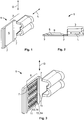
- Fig. 1
- shows a preferred embodiment of a blade connector according to the invention in a perspective view;
- Fig. 2
- shows the blade connector of
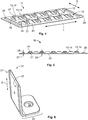
Fig. 1 in a side view along the guiding direction; - Fig. 3
- shows the blade connector of
Fig. 1 with two contacting plates in a perspective view; - Fig. 4
- shows one contacting plate of
Fig. 3 in a perspective view; - Fig. 5
- shows the contacting plate of
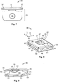
Fig. 4 in a side view; - Fig. 6
- shows a preferred embodiment of a second connector according to the invention in a perspective view;
- Fig. 7
- shows the second connector of
Fig. 6 in a top view along the guiding direction; - Fig. 8
- shows a first embodiment of a mounting cage according to the invention in a perspective view;
- Fig. 9
- shows a cutout of the mounting cage of
Fig. 8 in a perspective view; - Fig. 10
- shows the blade connector of
Fig. 3 in a mounting cage ofFig. 8 in a perspective view; - Fig. 11
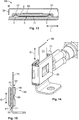
- shows a first embodiment of an assembly according to the invention with the blade connector of
Fig. 3 with the second connector ofFig. 6 inside the mounting cage ofFig. 8 in a mated state in a perspective view; - Fig. 12
- shows the assembly of
Fig. 11 in a cross-sectional view perpendicular to the longitudinal direction; - Fig. 13
- shows the assembly of
Fig. 11 in a cross-sectional view perpendicular to the guiding direction; - Fig. 14
- shows a second embodiment of an assembly according to the invention with the blade connector of
Fig. 3 with the second connector ofFig. 6 inside a second embodiment of a mounting cage according to the invention in a mated state in a perspective view; and - Fig. 15
- shows the embodiment of
Fig. 14 in a cross sectional view perpendicular to the longitudinal direction. - To simplify matters, the single elements, such as the second connector and the mounting cage are described with respect to the directions defined by the blade contact and are identical to said directions in the mated state.
- In the following, a first advantageous embodiment of a
blade connector 1 for aconnector assembly 69 according to the invention is described with respect toFigs. 1 and 2 . Theblade connector 1 basically extends along a longitudinal direction L. - Just by way of example, the
blade connector 1 is shown as a crimp connector with acrimp section 3. Instead of having acrimp section 3, theblade connector 1 may have any other section which is suitable for being connected with an electrical conductor (not shown). Alternatively, the blade connector may also form an end section of an electrical conductor, such as a bus bar or may be arranged on a compacted end section of a braided wire. - The
blade connector 1 comprises acontact surface plane 5 for being connected to a second connector 31 (a preferred embodiment of asecond connector 31 is described with respect toFigs. 6 and7 ). - On the
contact surface plane 5, theblade connector 1 comprises two guidingelements 7 which basically extend perpendicular to the longitudinal direction L along a guiding direction G. The guidingelements 7 are intended for guiding asecond connector 31 during mating and for providing positive locking between twoconnectors blade connector 1 with guidingelements 7 forms an advantageous embodiment of ablade connector 1 according to the invention, also embodiments without guidingelements 7 are possible. - The
contact surface plane 5 basically extends parallel with the longitudinal direction L and with the guiding direction G. - The guiding
elements 7 have an overall shape of a rib and protrude away from thecontact surface plane 5 perpendicular to the guiding direction G. The guidingelements 7 taper in a direction away from thecontact surface plane 5 and have overall trapezoidal cross-sectional shapes perpendicular to the guiding direction G. - The guiding
elements 7 are spaced apart from each other in the longitudinal direction L. It is clear for the person skilled in the art that the guidingelements 7 are parallel with each other, since both extend along the guiding direction G. - In the
area 9 of thecontact surface plane 5, which is arranged between the two guidingelements 7, theblade connector 1 may be provided with at least one contacting protrusion 13 (not yet shown). For example, thearea 9 may be provided with monolithically integrated solid structures, such as pyramids or ripples, which protrude away from thecontact surface plane 5. Theblade connector 1 may also be provided with monolithically integrated elastically deflectable contacting protrusions which extend away from thecontact surface plane 5 and are elastically deflectable towards the same. - In the following, a preferred embodiment of a
blade connector 1 according to the invention, which is provided with a plurality of contacting protrusions 13 which are arranged on contactingplates 11, and a contactingplate 11 according to the invention are described with respect toFigs. 3 to 5 . Theblade connector 1 as shown inFigs. 3 to 5 without the contactingplates 11 is identical to the one as described with respect toFigs. 1 and 2 . - Between the guiding
elements 7, or, in other words in thearea 9, theblade connector 1 is provided with two contactingplates 11, wherein each contactingplate 11 comprises a plurality of contacting protrusions 13 which are elastically deflectable. In particular, the elastically deflectable contacting protrusions 13 are leaf springs 14. - Just by way of example, the
blade connector 1 is shown with two contactingplates 11. The contacting protrusions 13 may also be provided on a single contactingplate 11 or on any other suitable number of contactingplates 11. In the case that theblade connector 1 is provided with 2 contactingplates 11, then these contactingplates 11 may abut each other in the guiding direction G to provide an effective covering of at least thearea 9 of thecontact surface plane 5. - The contacting
plates 11 are positioned on and conductively connected to thecontact surface plane 5. In a preferred embodiment, the contactingplates 11 are connected to thecontact surface plane 5 by laser welding. However, any other suitable method for electrically and mechanically connecting the contactingplates 11 to thecontact surface plane 5 may be used. Just by way of example, the contactingplates 11 may be connected to thecontact surface plane 5 by soldering, ultrasonic welding or riveting. - A contacting
plate 11 is now described in closer detail with respect toFigs. 4 and 5 . The contactingplate 11 may have an overall rectangular shape and comprise tworows 12 of contacting protrusions 13. Therows 12 extend parallel with the longitudinal direction L and are arranged next to each other in the guiding direction G. - The contacting protrusions 13 are preferably formed as leaf springs 14 which are monolithically formed with the contacting
plate 11. Each contacting protrusion 13 is connected via abase 15 with the contactingplate 11 and comprises afree end 17 with which the contacting protrusion 13 extends away from the contactingplate 11. Each contacting protrusion 13 preferably extends basically parallel with the guiding direction G. - Preferably, the contacting protrusions 13 of one
row 12 are arranged in an alternating manner with each contacting protrusion 13 pointing with itsfree end 17 in a direction opposite to a direction of an adjacent contact protrusion 13. In this case, an adjacent contacting protrusion 13 refers to a neighboring contacting protrusion 13 in thesame row 12. - At the
free end 17, each contacting protrusion 13 may have abent section 19, in which atip 21 of the contacting protrusion 13 is bent back towards the contactingplate 11. Thebent section 19 may protect the contacting protrusion 13 from being torn away from the contactingplate 11 when a second connector is moved along theblade connector 1 in the guiding direction G. - The contacting protrusions 13 are elastically deflectable towards the
contact surface plane 5 or, in other words, to abody 23 of the contactingplate 11. - In order to prevent over-bending of the contacting protrusions 13 by a second connector and, as a result thereof, plastic deformation of the contacting protrusions 13, the contacting
plate 11 is preferably provided withspacers 25. Just as an exemplary embodiment, the contactingplate 11 is shown with twospacers 25. Thespacers 25 are non-deflectable or at least less elastic than the leaf springs 14. - The
spacers 25 may space asecond connector 31 from thecontact surface plane 5 such that the contacting protrusions 13 can only be deflected as long as thespacers 25 do not prevent a further movement of asecond connector 31 towards thecontact surface plane 5. This is achieved in that thespacers 25 define adistance 27 from thecontact surface plane 5, which is smaller than a protrudinglength 29 with which the contacting protrusion 13 protrude away from thecontact surface plane 5 perpendicular to the longitudinal direction L and to the guiding direction G in a non-deflected state (as shown inFigs. 3 to 5 ). - The
spacers 25 preferably extend along the guiding direction G. According to a preferred embodiment (as shown in the figures) thespacers 25 can be spaced apart from each other with the tworows 12 of contacting protrusions 13 between them. - In the following, a preferred embodiment of a
second connector 31, according to the invention, is described with respect toFigs. 6 and7 . Thesecond connector 31 may be a blade connector or any other flat connector. Just by way of example, thesecond connector 31 is shown with anangular mounting section 33 with a through-hole 35. Thesecond connector 31 may also be provided with a crimp section or any other suitable mountingsection 33. - The second connector comprises two
complementarily guiding elements 37 which are formed complementary to the guidingelements 7 of theblade connector 1. Thecomplementary guiding elements 37 extend along a guiding direction G which is identical to the guiding direction G of theblade connector 1 when thesecond connector 31 is mated with theblade connector 1. Thecomplementary guiding elements 37 taper into acontact surface plane 5 of thesecond connector 31 and have each a trapezoidal cross-sectional shape in a cross section perpendicular to the guiding direction G. Eachcomplementary guiding element 37 has the overall shape of a groove longitudinally extending along the guiding direction G. - The
complementary guiding elements 37 are spaced apart from each other in a direction perpendicular to the guiding direction G which extends along the longitudinal direction L of theblade connector 1 in the mated state. Thecontact surface plane 5 between the twocomplementary guiding elements 37 is preferably smooth and undisturbed. However, this is just exemplarily. Thecontact surface plane 5 may also be provided with at least one contacting protrusion 13. Especially in the case that theblade connector 1 is formed without a contacting protrusion 13, thesecond connector 31 may be provided with at least one such contacting protrusion 13. - In the following, a first advantageous embodiment of a mounting
cage 39 is described with respect toFigs. 8 and 9 . - The mounting
cage 39 is preferably formed as a stamp-bent part and has an overall shape of a box. The mountingcage 39 comprises afirst receiving section 41 for theblade connector 1 and asecond receiving section 43 for thesecond connector 31. Thefirst receiving section 41 is accessible through ablade opening 45. - Preferably, a side of the mounting
cage 39, which lies opposite to theblade opening 45, is closed by anentrance preventing wall 47. Preferably, thefirst receiving section 41 extends continuously from theblade opening 45 to theentrance preventing wall 47. Theentrance preventing wall 47 extends preferably perpendicular to the longitudinal direction L of theblade connector 1. - On two opposing
sides 49 which oppose each other in the guiding direction G, the mountingcage 39 is provided with two lockingmembers 51 which protrude into the mountingcage 39 and which separate thefirst receiving section 41 from thesecond receiving section 43. The lockingmembers 51 are adapted to positively lock ablade connector 1 which is inserted in thefirst receiving section 41 against a movement towards thesecond receiving section 43. The lockingmembers 51 are monolithically formed with the mountingcage 39. - On each of the
sides 49, the mountingcage 39 is provided with aninsertion opening 53 for thesecond connector 31. However, the mountingcage 39 may also be provided with asingle insertion opening 53. If the mountingcage 39 comprises twoinsertion openings 53 which are arranged opposite to each other in the guiding direction G, then the mountingcage 39 may be used for two different insertion directions of asecond connector 31. - The mounting
cage 39 comprises aclamping device 55 which is preferably formed monolithically with the mountingcage 39. The clampingdevice 55 is preferably arranged such that thesecond receiving section 43 is arranged between the clampingdevice 55 and thefirst receiving section 41. By this, the clampingdevice 55 may exert pressure on thesecond connector 31 towards theblade connector 1 in the mated state. The clampingdevice 55 may be adapted with respect to its mechanical properties only because the electrical contact between theblade connector 1 and thesecond connector 31 will be established by the direct contact between these items and especially by thecontact surface planes 5 of theconnectors - When no
second connector 31 is inserted in the mountingcage 39, then theclamping device 55 preferably protrudes into thesecond receiving section 43. Upon insertion of thesecond connector 31 into thesecond receiving section 43, the clampingdevice 55 is elastically deflected away from thesecond receiving section 43 and exerts a pressure on thesecond connector 31. - In order to provide a stable and compact mounting
cage 39 and to allow the insertion of thesecond connector 31 from two different directions perpendicular to the guiding direction G, the clampingdevice 55 is shaped as a leaf spring which is connected to the mountingcage 39 at two opposing ends 57. Therefore, the clampingdevice 55 does not comprise a free end which may be damaged when asecond connector 31 is pushed against said free end during insertion into thesecond receiving section 43. - However, this does not exclude the possibility of providing the mounting
cage 39 with a leaf spring with a free end. In this case, the mountingcage 39 would preferably be provided with asingle insertion opening 53 for thesecond connector 31 in such the insertion direction for thesecond connector 31 is identical to a direction in which the free end of the leaf spring extends. - Preferably, the clamping
device 55 protrudes from theboundary 59 of aclamping device opening 61 into the mountingcage 39. Theclamping device opening 61 is continuously surrounded bymaterial 63 from which the mountingcage 39 is formed. Theclamping device opening 61 is preferably arranged in awall 65 which is arranged adjacent to thesecond receiving section 43. - The mounting
cage 39 may further be provided with a guidingwall 67 which extends from thewall 65 in the direction of theblade opening 45. The guidingwall 67 extends basically along the guiding direction G and parallel with theentrance preventing wall 47. During insertion of asecond connector 31, thesecond connector 31 may be guided between the guidingwall 67 and theentrance preventing wall 47. -
Fig. 10 shows ablade connector 1 as described with respect toFig. 3 in a mountingcage 39 which is described with respect toFigs. 8 and 9 . - The
contact surface plane 5 of theblade connector 1 is completely received in the mountingcage 39. The lockingmembers 51 are bent around theblade connector 1 such that the mountingcage 39 is captively connected to theblade connector 1. Thereby, each lockingmember 51 is at least partially arranged between thecontact surface plane 5 of theblade connector 1 and thesecond receiving section 43. On thecontact surface plane 5 of theblade connector 1, each lockingmember 51 is at least partially arranged between the guidingelements 7. - With the
blade connector 1 being inserted in thefirst receiving section 41 through theblade opening 45, the mountingcage 39 is basically closed except for the twoinsertion openings 53 for thesecond connector 31. The term "closed" refers to being closed for objects of the size of theblade connector 1 or thesecond connector 31. - In the following, the mated state M of a
blade connector 1 and asecond connector 31 which are mated inside a mountingcage 39, according to the invention, is described with respect toFigs. 11 to 13 . Thereby theblade connector 1, thesecond connector 31 and the mountingcage 39 are identical to the elements as described with respect toFigs. 3 to 10 . - The
blade connector 1, thesecond connector 31 and the mountingcage 39 together form an advantageous embodiment of anassembly 69 according to the invention. It should be noted that anassembly 69 may also be formed by ablade connector 1 according to the invention and asecond connector 31 according to the invention only. - In the mated state M, the
second connector 31 is inserted in thesecond receiving section 43. The guidingelements 7 of theblade connector 1 are seated in thecomplementary guiding elements 37 of thesecond connector 31. The clampingdevice 55 exerts pressure on thesecond connector 31 in the direction towards thecontact surface plane 5 of theblade connector 1. Thesecond connector 31 elastically deflects the contacting protrusions 13 so that the contacting protrusions exert a counter pressure towards thesecond connector 31. Thereby, thesecond connector 31 is electrically connected to theblade connector 1. - In the mated state, the
assembly 69 effectively secures the relative position of thesecond connector 31 to theblade connector 1, at least along the longitudinal direction L. - For reaching the mated state M, the
blade connector 1 together with a captively connected mountingcage 39 can be moved along the guiding direction G onto thesecond connector 31. - The
second connector 31 may be fixated to another element (not shown). During movement of theblade connector 1, thesecond connector 31 may penetrate through one of theinsertion openings 53 into thesecond receiving section 43. Thereby, theblade connector 1 and thesecond connector 31 may be mutually guided along each other by the interaction of the guidingelements 7 and thecomplementary guiding elements 37. -
Figs. 14 and 15 show a second embodiment of anassembly 69 according to the invention. For the sake of clarity, only the differences with respect to the previously shown embodiment of theassembly 69 are described. - The mounting
cage 39 comprises areceptacle 71 for a clampingplate 73. Thereceptacle 71 may be formed as an extension of thesecond receptacle 43 in the direction of theclamping device 55. This can be achieved by aclamping device 55 which does not protrude towards the firstreceptacle receiving section 41 as far as theclamping device 55 of the first embodiment, in the case that the overall shape and size of the mountingcage 39 of the second embodiment is to be similar to the mountingcage 39 of the first embodiment. - The
receptacle 71 allows for mating thesecond connector 31 with theblade connector 1 with zero insertion force. Thereceptacle 71 extends thesecond receiving section 43 such that asecond connector 31 may be inserted into thesecond receiving section 43 without being pressed against theblade connector 1 by the clampingdevice 55. - Only after the
second connector 31 is inserted in thesecond receiving section 43, the clampingplate 73 may be inserted into thereceptacle 71 to transmit the pressure from the clampingdevice 55 onto thesecond connector 31. - For facilitating the insertion of the clamping
plate 73, the clampingplate 73 may be inserted through aninsertion opening 53 of the mountingcage 39 which is arranged opposite to theinsertion opening 53 through which thesecond connector 31 was inserted. -
- 1
- blade connector
- 3
- crimp section
- 5
- contact surface plane
- 7
- guiding elements
- 9
- area between two guiding elements
- 11
- contacting plate
- 12
- row
- 13
- contacting protrusion
- 14
- leaf spring
- 15
- base
- 17
- free end
- 19
- bent section
- 21
- tip
- 23
- body of the contacting plate
- 25
- spacer
- 27
- distance
- 29
- protruding length
- 31
- second connector
- 33
- mounting section
- 35
- through-hole
- 37
- complementary guiding element
- 39
- mounting cage
- 41
- first receiving section
- 43
- second receiving section
- 45
- blade opening
- 47
- entrance preventing wall
- 49
- side of the mounting cage
- 51
- locking member
- 53
- insertion opening
- 55
- clamping device
- 57
- ends of the clamping device
- 59
- boundary
- 61
- clamping device opening
- 63
- material
- 65
- wall
- 67
- guiding wall
- 71
- receptacle
- 73
- clamping plate
- G
- guiding direction
- L
- longitudinal direction
- M
- mated state
Claims (15)
- Connector assembly (69) for electrically contacting a blade connector (1) to a second connector (31), the connector assembly comprising a blade connector (1) which extends along a longitudinal direction (L), wherein the blade connector (1) comprises a contact surface plane (5) for being electrically connected to the second connector (31) in a mated state (M), characterized in that the assembly (69) further comprises a mounting cage (39) which is captively connected to the blade connector (1) and which comprises at least one clamping device (55) adapted to press the second connector (31) onto the contact surface plane (5) of the blade connector (1) in the mated state (M).
- Connector assembly (69) according to claim 1, characterized in that the blade connector (1) comprises at least one guiding element (7) which is arranged on the contact surface plane (5) and which extends basically perpendicular to the longitudinal direction (L) along a guiding direction (G).
- Connector assembly (69) according to claim 2, characterized in that the at least one guiding element (7) is formed as a rail, a rib or as a series of spot-like structures.
- Connector assembly (69) according to claim 2 or 3, characterized in that the at least one guiding element (7) has an overall trapezoidal cross-sectional shape perpendicular to the guiding direction (G).
- Connector assembly (69) according to any of claims 2 to 4, characterized in that the at least one guiding element (7) protrudes from the contact surface plane (5) perpendicular to the longitudinal direction (L) and the guiding direction (G).
- Connector assembly (69) according to any of claims 1 to 5, characterized in that the contact surface plane (5) is provided with at least one contacting protrusion (13) which protrudes away from the contact surface plane (5) perpendicular to the longitudinal direction (L).
- Connector assembly (69) according to claim 6, characterized in that the at least one contacting protrusion (13) is arranged between two guiding elements (7) which are spaced apart from each other along the longitudinal direction (L).
- Connector assembly (69) according to claim 6 or 7, characterized in that the at least one contacting protrusion (13) is elastically deflectable.
- Connector assembly (69) according to claim 8, characterized in that the at least one contacting protrusion (13) is a leaf spring (14).
- Connector assembly (69) according to any of claims 6 to 9, characterized in that a plurality of contacting protrusions (13) is monolithically integrated with a contacting plate (11) which is positioned on and conductively connected to the contact surface plane (5).
- Connector assembly (69) according to any of claims 2 to 10, characterized in that the connector assembly (69) further comprises a second connector (31) for being electrically connected to the contact surface plane (5) of the blade connector (1) in a mated state (M) and in that the second connector (31) is provided with at least one complementary guiding element (37) which is formed complementary to the at least one guiding element (7) of the blade connector (1).
- Connector assembly (69) according to claim 11, characterized in that, in the mated state (M), the at least one guiding element (7) of the blade connector (1) and the at least one complementary guiding element (37) are positively locked in the longitudinal direction (L).
- Connector assembly (69) according to claim 11 or 12, characterized in that the contact surface plane (5) of the blade connector (1) comprises at least one elastically deflectable contacting protrusion (13) and at least one non-deflectable spacer (25) adapted to separate the second connector (31) from the contact surface plane (5) at a distance (27) which is smaller than a protruding length (29) of the at least one contacting protrusion (13).
- Connector assembly (69) according to any of claims 1 to 13, characterized in that the mounting cage (39) comprises a receptacle (71) for at least one clamping plate (73) between the blade connector (1) and the at least one clamping device (55) in the mated state (M).
- Connector assembly (69) according to claim 14, characterized in that the assembly (69) further comprises at least one clamping plate (73) which is insertable into the receptacle (71).
Priority Applications (3)
| Application Number | Priority Date | Filing Date | Title |
|---|---|---|---|
| JP2016164218A JP6839944B2 (en) | 2015-08-31 | 2016-08-25 | Connector assembly with blade connectors |
| CN201610771189.3A CN106486806B (en) | 2015-08-31 | 2016-08-30 | Connector assembly with blade connector |
| US15/253,300 US9793620B2 (en) | 2015-08-31 | 2016-08-31 | Connector assembly with a blade connector |
Applications Claiming Priority (1)
| Application Number | Priority Date | Filing Date | Title |
|---|---|---|---|
| DE102015216632.5A DE102015216632A1 (en) | 2015-08-31 | 2015-08-31 | Arrangement for establishing an electrical connection between a flat contact and a high-current conductor |
Publications (2)
| Publication Number | Publication Date |
|---|---|
| EP3136516A1 true EP3136516A1 (en) | 2017-03-01 |
| EP3136516B1 EP3136516B1 (en) | 2018-06-20 |
Family
ID=54697501
Family Applications (2)
| Application Number | Title | Priority Date | Filing Date |
|---|---|---|---|
| EP15195936.8A Not-in-force EP3136516B1 (en) | 2015-08-31 | 2015-11-23 | Connector assembly with a blade connector |
| EP16185486.4A Active EP3145035B1 (en) | 2015-08-31 | 2016-08-24 | Arrangement for establishing an electrical connection between a tab contact and a high current conductor |
Family Applications After (1)
| Application Number | Title | Priority Date | Filing Date |
|---|---|---|---|
| EP16185486.4A Active EP3145035B1 (en) | 2015-08-31 | 2016-08-24 | Arrangement for establishing an electrical connection between a tab contact and a high current conductor |
Country Status (5)
| Country | Link |
|---|---|
| US (2) | US10218105B2 (en) |
| EP (2) | EP3136516B1 (en) |
| JP (2) | JP6839944B2 (en) |
| CN (2) | CN106486806B (en) |
| DE (1) | DE102015216632A1 (en) |
Cited By (7)
| Publication number | Priority date | Publication date | Assignee | Title |
|---|---|---|---|---|
| EP3252872A1 (en) * | 2016-05-31 | 2017-12-06 | TE Connectivity Germany GmbH | Connection cage for connecting two electrical flat contacts |
| CN113258372A (en) * | 2021-05-26 | 2021-08-13 | 宣城立讯精密工业有限公司 | Electrical connection kit and electrical connector |
| EP3896715A1 (en) * | 2020-04-14 | 2021-10-20 | Tyco Electronics France SAS | Fuse holding element configured to releasably cooperate with a conducting bar |
| EP3996212A1 (en) * | 2020-11-09 | 2022-05-11 | Aptiv Technologies Limited | Electrical connector assembly |
| TWI789587B (en) * | 2020-03-31 | 2023-01-11 | 映興電子股份有限公司 | Double knife butt connector |
| US11677175B2 (en) | 2021-05-26 | 2023-06-13 | Xuancheng Luxshare Precision Industry Co., Ltd. | Electrical connecting assembly and electrical connector |
| EP4401248A1 (en) * | 2023-01-13 | 2024-07-17 | Tyco Electronics Technology (SIP) Ltd. | Terminal, connector and connector assembly |
Families Citing this family (32)
| Publication number | Priority date | Publication date | Assignee | Title |
|---|---|---|---|---|
| DE102015216632A1 (en) * | 2015-08-31 | 2017-03-02 | Te Connectivity Germany Gmbh | Arrangement for establishing an electrical connection between a flat contact and a high-current conductor |
| DE102016221351A1 (en) * | 2016-10-28 | 2018-05-03 | Te Connectivity Germany Gmbh | Flat contact socket with extension arm |
| DE102016123081B4 (en) * | 2016-11-30 | 2018-06-14 | Amphenol-Tuchel Electronics Gmbh | Cylindrical high current contact connector socket |
| JP6787175B2 (en) * | 2017-02-22 | 2020-11-18 | 株式会社オートネットワーク技術研究所 | Multi-contact terminal |
| DE102017220185A1 (en) | 2017-11-13 | 2019-05-16 | Te Connectivity Germany Gmbh | female contact |
| CN109802258B (en) * | 2017-11-15 | 2022-01-25 | 富士康(昆山)电脑接插件有限公司 | Electric connector and combination thereof |
| JP2019110074A (en) * | 2017-12-20 | 2019-07-04 | 矢崎総業株式会社 | Connection terminal and connector |
| JP2019185885A (en) * | 2018-04-03 | 2019-10-24 | 矢崎総業株式会社 | Relay terminal and relay connector |
| US10181673B1 (en) * | 2018-05-29 | 2019-01-15 | Te Connectivity Corporation | Receptacle terminal for a junction box |
| US10389055B1 (en) * | 2018-06-20 | 2019-08-20 | Delphia Technologies, Llc | Electrical connector assembly |
| FR3094578B1 (en) | 2019-04-01 | 2021-12-10 | Aptiv Tech Ltd | Power connection device for electric heater and connection assembly comprising this device. |
| EP3783744B1 (en) * | 2019-08-23 | 2026-03-25 | Yazaki Europe Ltd. | Electric connection arrangement |
| JP7281087B2 (en) * | 2019-11-01 | 2023-05-25 | 株式会社オートネットワーク技術研究所 | Terminal connection structure |
| CN110957597B (en) * | 2019-12-27 | 2024-08-30 | 深圳乔合里科技股份有限公司 | Double-reed flat high-current terminal and assembling method thereof |
| DE102020001379B3 (en) * | 2020-03-03 | 2021-08-19 | Wieland-Werke Aktiengesellschaft | Arrangement of components for the transmission of electrical current |
| US11128078B1 (en) * | 2020-07-20 | 2021-09-21 | TE Connectivity Services Gmbh | Current carrying retention clip |
| DE102020121969A1 (en) | 2020-08-21 | 2022-02-24 | Amphenol-Tuchel Electronics Gesellschaft mit beschränkter Haftung | Locking zone for a plug contact element |
| JP2022150224A (en) * | 2021-03-26 | 2022-10-07 | 株式会社オートネットワーク技術研究所 | Terminal unit, first terminal, second terminal |
| DE102021112425A1 (en) | 2021-05-12 | 2022-11-17 | Te Connectivity Germany Gmbh | Vibration resistant high current electrical flat socket contact device |
| CN113725663B (en) * | 2021-08-25 | 2022-04-22 | 浙江普可医疗科技有限公司 | Sensor connecting device |
| EP4406068A4 (en) * | 2021-09-22 | 2025-01-01 | Ennovi Industries, Inc. | TILTED COIL COUPLER |
| KR102954731B1 (en) * | 2021-11-18 | 2026-04-21 | 한국단자공업 주식회사 | Connector assembly for electronic components |
| EP4231460A1 (en) * | 2022-02-17 | 2023-08-23 | Tyco Electronics France SAS | Contact element, electrical connector and electrical connector assembly |
| JP2023172374A (en) * | 2022-05-23 | 2023-12-06 | 古河電気工業株式会社 | Female terminals, wires with terminals, female connectors, wires with connectors, and wire harnesses |
| US20240204438A1 (en) * | 2022-12-20 | 2024-06-20 | Aptiv Technologies AG | High voltage electrical terminal with compliant contact insert |
| DE102023101116A1 (en) * | 2023-01-18 | 2024-07-18 | Te Connectivity Solutions Gmbh | Vibration-resistant electrical flat socket terminal |
| DE102024126223B3 (en) | 2024-09-12 | 2026-03-12 | Dinkle Electric Machinery (China) Co., Ltd. | PLUG CONNECTOR STRUCTURE |
| CN121886016A (en) * | 2024-10-11 | 2026-04-17 | 泰科电子(上海)有限公司 | Connector terminals, electrical connection assemblies and connectors |
| DE102024210639A1 (en) | 2024-11-06 | 2026-05-07 | Robert Bosch Gesellschaft mit beschränkter Haftung | Electrical cable with plug contour and method for manufacturing a plug contour on an electrical cable |
| DE102024004608A1 (en) | 2024-11-15 | 2026-05-21 | Dinkle Electric Machinery (China) Co., Ltd. | MULTI-CONTACT CONNECTION STRUCTURE |
| DE102024133494A1 (en) * | 2024-11-15 | 2026-05-21 | Dinkle Electric Machinery (China) Co., Ltd. | Multi-contact connection structure and connection plate thereof |
| DE102024004607A1 (en) | 2024-11-15 | 2026-05-21 | Dinkle Electric Machinery (China) Co., Ltd. | MULTI-CONTACT CONNECTION STRUCTURE |
Citations (3)
| Publication number | Priority date | Publication date | Assignee | Title |
|---|---|---|---|---|
| EP1089387A2 (en) * | 1999-09-27 | 2001-04-04 | F.C.I. - Framatome Connectors International | A modular female electrical terminal |
| EP1730818A1 (en) | 2004-03-30 | 2006-12-13 | Kostal Kontakt Systeme GmbH | Electrical socket contact for high current applications |
| EP2211425A1 (en) * | 2009-01-23 | 2010-07-28 | MTA S.p.A. | Female electrical terminal |
Family Cites Families (61)
| Publication number | Priority date | Publication date | Assignee | Title |
|---|---|---|---|---|
| US2997685A (en) * | 1956-06-05 | 1961-08-22 | Bryant Electric Co | Electrical connector |
| NL135884C (en) * | 1965-11-06 | |||
| DE1665132C3 (en) * | 1967-04-27 | 1975-09-25 | Multi-Contact Ag, Basel (Schweiz) | Electrical contact arrangement, in particular high-current contact arrangement |
| DE3330984A1 (en) * | 1983-08-27 | 1985-03-14 | Licentia Patent-Verwaltungs-Gmbh, 6000 Frankfurt | Device for the electrically conductive connection of two or more electrically conductive pins |
| US5399098A (en) * | 1993-10-29 | 1995-03-21 | Molex Incorporated | Electrical connector and terminal therefor for mating with a blade contact |
| ES2117799T3 (en) * | 1994-07-27 | 1998-08-16 | United Technologies Automotive | ELECTRICAL TERMINAL. |
| DE4433983A1 (en) * | 1994-09-23 | 1996-03-28 | Ackermann Albert Gmbh Co | Terminal block for electrical installations |
| US5588884A (en) * | 1995-09-08 | 1996-12-31 | Packard Hughes Interconnect Company | Stamped and formed contacts for a power connector |
| FR2740266B1 (en) * | 1995-10-20 | 1997-11-28 | Cinch Connecteurs Sa | DEVICE FOR CONNECTING TWO MALE TABS OF ELECTRICAL CONTACTS |
| US5911605A (en) * | 1997-10-16 | 1999-06-15 | Ui Automotive Dearborn, Inc. | Universal terminal connection |
| JPH11307159A (en) * | 1998-04-16 | 1999-11-05 | Kansei Corp | Electrical connection terminal |
| JP3783412B2 (en) * | 1998-06-16 | 2006-06-07 | 住友電装株式会社 | Circuit board |
| JP3736128B2 (en) * | 1998-08-11 | 2006-01-18 | 株式会社日立製作所 | Multicore conductor wire and manufacturing method thereof |
| JP2000243498A (en) * | 1999-02-19 | 2000-09-08 | Furukawa Electric Co Ltd:The | Box type female terminal |
| CH694478A5 (en) * | 2000-01-20 | 2005-01-31 | Multi Holding Ag | Contact element. |
| US6485337B2 (en) * | 2000-08-30 | 2002-11-26 | Delphi Technologies, Inc. | Electrical connector |
| US6860768B2 (en) * | 2000-09-15 | 2005-03-01 | Alcoa Fujikura Limited | Combination sleeve and spring cage incorporated into a one-piece female terminal for interengaging a corresponding male terminal and method of configuring such a sleeve and spring cage from a blank shape |
| US6264509B1 (en) * | 2001-01-10 | 2001-07-24 | Yazaki North America, Inc. | High cycle terminal with protected failsafe contact |
| US20030060090A1 (en) * | 2001-09-21 | 2003-03-27 | Allgood Christopher L. | High current automotive electrical connector and terminal |
| FR2830374B1 (en) * | 2001-10-03 | 2004-09-10 | Framatome Connectors Int | CONNECTION DEVICE COMPRISING A DOUBLE CONTACT, PARTICULARLY FOR MEDIUM VOLTAGE APPLICATIONS |
| EP1429424A1 (en) * | 2002-12-10 | 2004-06-16 | Meccanotecnica Codognese S.p.A. | Electric terminal |
| CN2710203Y (en) * | 2003-10-22 | 2005-07-13 | 莫列斯公司 | Card connector assembly |
| DE10351540B3 (en) * | 2003-11-03 | 2005-08-11 | Intedis Gmbh & Co. Kg | Flat plug socket |
| JP2005196975A (en) * | 2003-12-26 | 2005-07-21 | Jst Mfg Co Ltd | connector |
| CN2755810Y (en) * | 2004-12-14 | 2006-02-01 | 富港电子(东莞)有限公司 | Memory card connector |
| DE102005043601B4 (en) * | 2005-09-12 | 2007-06-14 | Yazaki Europe Ltd., Hemel Hempstead | Contact retaining clip for mounting on a busbar and contact support therefrom |
| US7241180B1 (en) | 2006-01-31 | 2007-07-10 | Medtronic, Inc. | Medical electrical lead connector assembly |
| DE102007016070A1 (en) | 2007-04-03 | 2008-10-09 | Lear Corp., Southfield | Electrical connection arrangement and method for using the electrical connection arrangement |
| US7374460B1 (en) * | 2007-04-17 | 2008-05-20 | Traxxas Lp | Electrical connector assembly |
| EP1986272B1 (en) * | 2007-04-26 | 2011-08-10 | Multi-Holding AG | Contact device for providing an electrical contact between flat current carrying line elements |
| EP2048746B1 (en) * | 2007-08-13 | 2016-10-05 | Tyco Electronics Nederland B.V. | Busbar connection system |
| US7766706B2 (en) * | 2008-11-17 | 2010-08-03 | J. S. T. Corporation | Female terminal assembly with compression clip |
| JP5282540B2 (en) * | 2008-11-21 | 2013-09-04 | 日立電線株式会社 | Male-female connection structure |
| JP5173777B2 (en) * | 2008-12-15 | 2013-04-03 | 矢崎総業株式会社 | Male terminal structure |
| US8668531B2 (en) * | 2009-07-03 | 2014-03-11 | Yazaki Corporation | Terminal |
| JP5381492B2 (en) * | 2009-08-19 | 2014-01-08 | 住友電装株式会社 | Female terminal bracket |
| JP2011070897A (en) * | 2009-09-25 | 2011-04-07 | Sumitomo Wiring Syst Ltd | Lever type connector |
| KR101598633B1 (en) * | 2009-11-11 | 2016-02-29 | 타이코에이엠피 주식회사 | Terminal for connector |
| DE202010003555U1 (en) * | 2010-03-16 | 2010-07-08 | Rosenberger Hochfrequenztechnik Gmbh & Co. Kg | High Power Connectors |
| JP2011210429A (en) * | 2010-03-29 | 2011-10-20 | Aisin Aw Co Ltd | Electric connection device |
| CH702863B1 (en) * | 2010-03-30 | 2014-12-15 | Multi Holding Ag | Connecting element. |
| DE202010010827U1 (en) * | 2010-07-29 | 2010-10-21 | Rosenberger Hochfrequenztechnik Gmbh & Co. Kg | High Power Connectors |
| JP5632225B2 (en) * | 2010-07-30 | 2014-11-26 | 矢崎総業株式会社 | Terminal connection structure |
| JP5083847B1 (en) * | 2011-06-07 | 2012-11-28 | 日本航空電子工業株式会社 | Contact elements and connectors |
| JP5723694B2 (en) * | 2011-06-21 | 2015-05-27 | 矢崎総業株式会社 | Female terminal |
| JP5723695B2 (en) * | 2011-06-21 | 2015-05-27 | 矢崎総業株式会社 | Female terminal |
| US8388389B2 (en) * | 2011-07-07 | 2013-03-05 | Tyco Electronics Corporation | Electrical connectors having opposing electrical contacts |
| DE102011085700A1 (en) * | 2011-11-03 | 2013-05-08 | Bayerische Motoren Werke Aktiengesellschaft | High current connectors for automotive applications |
| JP2013101795A (en) * | 2011-11-08 | 2013-05-23 | Sumitomo Wiring Syst Ltd | Bus bar connection structure of current detector |
| US8821170B1 (en) * | 2012-07-19 | 2014-09-02 | Robert Hla Thein | Electrical contact having multiple cantilevered beams |
| JP6124074B2 (en) * | 2013-03-21 | 2017-05-10 | 住友電装株式会社 | Female terminal |
| US9070990B2 (en) * | 2013-05-21 | 2015-06-30 | Tyco Electronics Corporation | Power connector having opposing contact springs |
| DE202013103444U1 (en) * | 2013-07-31 | 2014-11-04 | Weidmüller Interface GmbH & Co. KG | Contact element for a plug-in arrangement of a particular externally guided bus system |
| EP3082177B1 (en) * | 2013-12-13 | 2019-02-20 | Hitachi Automotive Systems, Ltd. | Secondary cell module |
| JP6369029B2 (en) * | 2014-01-28 | 2018-08-08 | オムロン株式会社 | connector |
| DE102014001302A1 (en) * | 2014-01-31 | 2014-08-14 | Daimler Ag | Device for fastening electrically conductive cable lug on external electrical contact element, has housing with contact element, and housing non-positively pressing contact portion of conductive cable lug against carrier element |
| CN104037523B (en) * | 2014-06-13 | 2016-05-11 | 四川永贵科技有限公司 | A kind of large current terminal |
| JP6591146B2 (en) * | 2014-07-08 | 2019-10-16 | 日本航空電子工業株式会社 | Contact and connector including the same |
| DE102015216632A1 (en) * | 2015-08-31 | 2017-03-02 | Te Connectivity Germany Gmbh | Arrangement for establishing an electrical connection between a flat contact and a high-current conductor |
| US9893450B2 (en) * | 2015-09-25 | 2018-02-13 | Hirose Electric Co., Ltd. | Electrical connecting member and electrical connector having the same |
| DE102016201103B4 (en) * | 2016-01-26 | 2023-10-05 | Lisa Dräxlmaier GmbH | Contact part |
-
2015
- 2015-08-31 DE DE102015216632.5A patent/DE102015216632A1/en active Pending
- 2015-11-23 EP EP15195936.8A patent/EP3136516B1/en not_active Not-in-force
-
2016
- 2016-08-24 EP EP16185486.4A patent/EP3145035B1/en active Active
- 2016-08-25 JP JP2016164218A patent/JP6839944B2/en not_active Expired - Fee Related
- 2016-08-25 JP JP2016164249A patent/JP6783588B2/en active Active
- 2016-08-30 CN CN201610771189.3A patent/CN106486806B/en not_active Expired - Fee Related
- 2016-08-30 CN CN201610773362.3A patent/CN106486791B/en active Active
- 2016-08-31 US US15/253,282 patent/US10218105B2/en active Active
- 2016-08-31 US US15/253,300 patent/US9793620B2/en not_active Expired - Fee Related
Patent Citations (3)
| Publication number | Priority date | Publication date | Assignee | Title |
|---|---|---|---|---|
| EP1089387A2 (en) * | 1999-09-27 | 2001-04-04 | F.C.I. - Framatome Connectors International | A modular female electrical terminal |
| EP1730818A1 (en) | 2004-03-30 | 2006-12-13 | Kostal Kontakt Systeme GmbH | Electrical socket contact for high current applications |
| EP2211425A1 (en) * | 2009-01-23 | 2010-07-28 | MTA S.p.A. | Female electrical terminal |
Cited By (10)
| Publication number | Priority date | Publication date | Assignee | Title |
|---|---|---|---|---|
| EP3252872A1 (en) * | 2016-05-31 | 2017-12-06 | TE Connectivity Germany GmbH | Connection cage for connecting two electrical flat contacts |
| US10050400B2 (en) | 2016-05-31 | 2018-08-14 | Te Connectivity Germany Gmbh | Connection cage for connecting two electrical flat contacts |
| TWI789587B (en) * | 2020-03-31 | 2023-01-11 | 映興電子股份有限公司 | Double knife butt connector |
| EP3896715A1 (en) * | 2020-04-14 | 2021-10-20 | Tyco Electronics France SAS | Fuse holding element configured to releasably cooperate with a conducting bar |
| US11295920B2 (en) | 2020-04-14 | 2022-04-05 | Tyco Electronics France Sas | Fuse holding element configured to releasibly cooperate with a conducting bar |
| EP3996212A1 (en) * | 2020-11-09 | 2022-05-11 | Aptiv Technologies Limited | Electrical connector assembly |
| CN113258372A (en) * | 2021-05-26 | 2021-08-13 | 宣城立讯精密工业有限公司 | Electrical connection kit and electrical connector |
| US11658434B2 (en) | 2021-05-26 | 2023-05-23 | Xuancheng Luxshare Precision Industry Co., Ltd. | Electrical connecting assembly and electrical connector |
| US11677175B2 (en) | 2021-05-26 | 2023-06-13 | Xuancheng Luxshare Precision Industry Co., Ltd. | Electrical connecting assembly and electrical connector |
| EP4401248A1 (en) * | 2023-01-13 | 2024-07-17 | Tyco Electronics Technology (SIP) Ltd. | Terminal, connector and connector assembly |
Also Published As
| Publication number | Publication date |
|---|---|
| JP6783588B2 (en) | 2020-11-11 |
| CN106486791A (en) | 2017-03-08 |
| JP2017054808A (en) | 2017-03-16 |
| US9793620B2 (en) | 2017-10-17 |
| JP2017050281A (en) | 2017-03-09 |
| EP3136516B1 (en) | 2018-06-20 |
| CN106486806A (en) | 2017-03-08 |
| US20170062966A1 (en) | 2017-03-02 |
| CN106486791B (en) | 2021-09-03 |
| CN106486806B (en) | 2020-02-11 |
| EP3145035B1 (en) | 2020-07-01 |
| US20170062955A1 (en) | 2017-03-02 |
| JP6839944B2 (en) | 2021-03-10 |
| US10218105B2 (en) | 2019-02-26 |
| DE102015216632A1 (en) | 2017-03-02 |
| EP3145035A1 (en) | 2017-03-22 |
Similar Documents
| Publication | Publication Date | Title |
|---|---|---|
| EP3136516B1 (en) | Connector assembly with a blade connector | |
| US10381766B2 (en) | Terminal fitting | |
| US9033722B2 (en) | Electric connection terminal and connector including the same | |
| EP2572405B1 (en) | Contact spring for plug connector socket | |
| US9033743B2 (en) | Electric connection terminal and connector including the same | |
| US20140045390A1 (en) | Tandem Multi-Fork Push-In Pin | |
| KR102227471B1 (en) | Power terminal connector | |
| US20210184382A1 (en) | Terminal fitting | |
| US9166343B1 (en) | Mezzanine receptacle connector | |
| US9312643B2 (en) | Mezzanine connector assembly | |
| US11264752B1 (en) | Planar terminal connector having an additional contact spring | |
| CN114175410A (en) | Safe, Robust, Compact Connector | |
| EP2698881A1 (en) | Connector | |
| WO2013156490A1 (en) | Resilient contact device, contact arrangement and plug type connector | |
| EP2418738B1 (en) | Terminal for connecting wires to printed circuit boards | |
| EP3624274B1 (en) | Contact assembly | |
| EP0320310A2 (en) | High contact pressure insulation displacement terminal for multi-strand wire | |
| KR101533808B1 (en) | Connector | |
| WO2013153051A1 (en) | Electrical plug type connector, in particular for mounting on printed circuit boards, having a separate contact carrier plate | |
| EP3588678B1 (en) | Connection structure of cable and terminal | |
| EP2290749A1 (en) | Connector | |
| KR20130018111A (en) | Electrical connector device and receptacle connector used in the electrical connector device | |
| EP2859622B1 (en) | Terminal connection structure | |
| EP4726933A1 (en) | Connector terminal, electrical connection assembly and connector | |
| JP5137654B2 (en) | Connection terminal connection structure and connection method |
Legal Events
| Date | Code | Title | Description |
|---|---|---|---|
| PUAI | Public reference made under article 153(3) epc to a published international application that has entered the european phase |
Free format text: ORIGINAL CODE: 0009012 |
|
| AK | Designated contracting states |
Kind code of ref document: A1 Designated state(s): AL AT BE BG CH CY CZ DE DK EE ES FI FR GB GR HR HU IE IS IT LI LT LU LV MC MK MT NL NO PL PT RO RS SE SI SK SM TR |
|
| AX | Request for extension of the european patent |
Extension state: BA ME |
|
| 17P | Request for examination filed |
Effective date: 20170901 |
|
| RBV | Designated contracting states (corrected) |
Designated state(s): AL AT BE BG CH CY CZ DE DK EE ES FI FR GB GR HR HU IE IS IT LI LT LU LV MC MK MT NL NO PL PT RO RS SE SI SK SM TR |
|
| GRAP | Despatch of communication of intention to grant a patent |
Free format text: ORIGINAL CODE: EPIDOSNIGR1 |
|
| INTG | Intention to grant announced |
Effective date: 20180122 |
|
| RAP1 | Party data changed (applicant data changed or rights of an application transferred) |
Owner name: TYCO ELECTRONICS UK LTD. Owner name: TE CONNECTIVITY GERMANY GMBH |
|
| GRAS | Grant fee paid |
Free format text: ORIGINAL CODE: EPIDOSNIGR3 |
|
| GRAA | (expected) grant |
Free format text: ORIGINAL CODE: 0009210 |
|
| AK | Designated contracting states |
Kind code of ref document: B1 Designated state(s): AL AT BE BG CH CY CZ DE DK EE ES FI FR GB GR HR HU IE IS IT LI LT LU LV MC MK MT NL NO PL PT RO RS SE SI SK SM TR |
|
| REG | Reference to a national code |
Ref country code: GB Ref legal event code: FG4D |
|
| REG | Reference to a national code |
Ref country code: IE Ref legal event code: FG4D |
|
| REG | Reference to a national code |
Ref country code: AT Ref legal event code: REF Ref document number: 1011226 Country of ref document: AT Kind code of ref document: T Effective date: 20180715 |
|
| REG | Reference to a national code |
Ref country code: DE Ref legal event code: R096 Ref document number: 602015012473 Country of ref document: DE |
|
| REG | Reference to a national code |
Ref country code: FR Ref legal event code: PLFP Year of fee payment: 4 |
|
| REG | Reference to a national code |
Ref country code: NL Ref legal event code: MP Effective date: 20180620 |
|
| PG25 | Lapsed in a contracting state [announced via postgrant information from national office to epo] |
Ref country code: SE Free format text: LAPSE BECAUSE OF FAILURE TO SUBMIT A TRANSLATION OF THE DESCRIPTION OR TO PAY THE FEE WITHIN THE PRESCRIBED TIME-LIMIT Effective date: 20180620 Ref country code: LT Free format text: LAPSE BECAUSE OF FAILURE TO SUBMIT A TRANSLATION OF THE DESCRIPTION OR TO PAY THE FEE WITHIN THE PRESCRIBED TIME-LIMIT Effective date: 20180620 Ref country code: BG Free format text: LAPSE BECAUSE OF FAILURE TO SUBMIT A TRANSLATION OF THE DESCRIPTION OR TO PAY THE FEE WITHIN THE PRESCRIBED TIME-LIMIT Effective date: 20180920 Ref country code: NO Free format text: LAPSE BECAUSE OF FAILURE TO SUBMIT A TRANSLATION OF THE DESCRIPTION OR TO PAY THE FEE WITHIN THE PRESCRIBED TIME-LIMIT Effective date: 20180920 Ref country code: FI Free format text: LAPSE BECAUSE OF FAILURE TO SUBMIT A TRANSLATION OF THE DESCRIPTION OR TO PAY THE FEE WITHIN THE PRESCRIBED TIME-LIMIT Effective date: 20180620 |
|
| REG | Reference to a national code |
Ref country code: LT Ref legal event code: MG4D |
|
| PG25 | Lapsed in a contracting state [announced via postgrant information from national office to epo] |
Ref country code: GR Free format text: LAPSE BECAUSE OF FAILURE TO SUBMIT A TRANSLATION OF THE DESCRIPTION OR TO PAY THE FEE WITHIN THE PRESCRIBED TIME-LIMIT Effective date: 20180921 Ref country code: RS Free format text: LAPSE BECAUSE OF FAILURE TO SUBMIT A TRANSLATION OF THE DESCRIPTION OR TO PAY THE FEE WITHIN THE PRESCRIBED TIME-LIMIT Effective date: 20180620 Ref country code: LV Free format text: LAPSE BECAUSE OF FAILURE TO SUBMIT A TRANSLATION OF THE DESCRIPTION OR TO PAY THE FEE WITHIN THE PRESCRIBED TIME-LIMIT Effective date: 20180620 Ref country code: HR Free format text: LAPSE BECAUSE OF FAILURE TO SUBMIT A TRANSLATION OF THE DESCRIPTION OR TO PAY THE FEE WITHIN THE PRESCRIBED TIME-LIMIT Effective date: 20180620 |
|
| REG | Reference to a national code |
Ref country code: AT Ref legal event code: MK05 Ref document number: 1011226 Country of ref document: AT Kind code of ref document: T Effective date: 20180620 |
|
| PG25 | Lapsed in a contracting state [announced via postgrant information from national office to epo] |
Ref country code: NL Free format text: LAPSE BECAUSE OF FAILURE TO SUBMIT A TRANSLATION OF THE DESCRIPTION OR TO PAY THE FEE WITHIN THE PRESCRIBED TIME-LIMIT Effective date: 20180620 |
|
| PG25 | Lapsed in a contracting state [announced via postgrant information from national office to epo] |
Ref country code: SK Free format text: LAPSE BECAUSE OF FAILURE TO SUBMIT A TRANSLATION OF THE DESCRIPTION OR TO PAY THE FEE WITHIN THE PRESCRIBED TIME-LIMIT Effective date: 20180620 Ref country code: EE Free format text: LAPSE BECAUSE OF FAILURE TO SUBMIT A TRANSLATION OF THE DESCRIPTION OR TO PAY THE FEE WITHIN THE PRESCRIBED TIME-LIMIT Effective date: 20180620 Ref country code: PL Free format text: LAPSE BECAUSE OF FAILURE TO SUBMIT A TRANSLATION OF THE DESCRIPTION OR TO PAY THE FEE WITHIN THE PRESCRIBED TIME-LIMIT Effective date: 20180620 Ref country code: IS Free format text: LAPSE BECAUSE OF FAILURE TO SUBMIT A TRANSLATION OF THE DESCRIPTION OR TO PAY THE FEE WITHIN THE PRESCRIBED TIME-LIMIT Effective date: 20181020 Ref country code: RO Free format text: LAPSE BECAUSE OF FAILURE TO SUBMIT A TRANSLATION OF THE DESCRIPTION OR TO PAY THE FEE WITHIN THE PRESCRIBED TIME-LIMIT Effective date: 20180620 Ref country code: AT Free format text: LAPSE BECAUSE OF FAILURE TO SUBMIT A TRANSLATION OF THE DESCRIPTION OR TO PAY THE FEE WITHIN THE PRESCRIBED TIME-LIMIT Effective date: 20180620 Ref country code: CZ Free format text: LAPSE BECAUSE OF FAILURE TO SUBMIT A TRANSLATION OF THE DESCRIPTION OR TO PAY THE FEE WITHIN THE PRESCRIBED TIME-LIMIT Effective date: 20180620 |
|
| PG25 | Lapsed in a contracting state [announced via postgrant information from national office to epo] |
Ref country code: ES Free format text: LAPSE BECAUSE OF FAILURE TO SUBMIT A TRANSLATION OF THE DESCRIPTION OR TO PAY THE FEE WITHIN THE PRESCRIBED TIME-LIMIT Effective date: 20180620 Ref country code: SM Free format text: LAPSE BECAUSE OF FAILURE TO SUBMIT A TRANSLATION OF THE DESCRIPTION OR TO PAY THE FEE WITHIN THE PRESCRIBED TIME-LIMIT Effective date: 20180620 |
|
| REG | Reference to a national code |
Ref country code: DE Ref legal event code: R097 Ref document number: 602015012473 Country of ref document: DE |
|
| PLBE | No opposition filed within time limit |
Free format text: ORIGINAL CODE: 0009261 |
|
| STAA | Information on the status of an ep patent application or granted ep patent |
Free format text: STATUS: NO OPPOSITION FILED WITHIN TIME LIMIT |
|
| 26N | No opposition filed |
Effective date: 20190321 |
|
| PG25 | Lapsed in a contracting state [announced via postgrant information from national office to epo] |
Ref country code: DK Free format text: LAPSE BECAUSE OF FAILURE TO SUBMIT A TRANSLATION OF THE DESCRIPTION OR TO PAY THE FEE WITHIN THE PRESCRIBED TIME-LIMIT Effective date: 20180620 |
|
| REG | Reference to a national code |
Ref country code: CH Ref legal event code: PL |
|
| PG25 | Lapsed in a contracting state [announced via postgrant information from national office to epo] |
Ref country code: MC Free format text: LAPSE BECAUSE OF FAILURE TO SUBMIT A TRANSLATION OF THE DESCRIPTION OR TO PAY THE FEE WITHIN THE PRESCRIBED TIME-LIMIT Effective date: 20180620 Ref country code: LU Free format text: LAPSE BECAUSE OF NON-PAYMENT OF DUE FEES Effective date: 20181123 |
|
| REG | Reference to a national code |
Ref country code: BE Ref legal event code: MM Effective date: 20181130 |
|
| REG | Reference to a national code |
Ref country code: IE Ref legal event code: MM4A |
|
| PG25 | Lapsed in a contracting state [announced via postgrant information from national office to epo] |
Ref country code: SI Free format text: LAPSE BECAUSE OF FAILURE TO SUBMIT A TRANSLATION OF THE DESCRIPTION OR TO PAY THE FEE WITHIN THE PRESCRIBED TIME-LIMIT Effective date: 20180620 Ref country code: LI Free format text: LAPSE BECAUSE OF NON-PAYMENT OF DUE FEES Effective date: 20181130 Ref country code: CH Free format text: LAPSE BECAUSE OF NON-PAYMENT OF DUE FEES Effective date: 20181130 |
|
| PG25 | Lapsed in a contracting state [announced via postgrant information from national office to epo] |
Ref country code: IE Free format text: LAPSE BECAUSE OF NON-PAYMENT OF DUE FEES Effective date: 20181123 |
|
| PG25 | Lapsed in a contracting state [announced via postgrant information from national office to epo] |
Ref country code: BE Free format text: LAPSE BECAUSE OF NON-PAYMENT OF DUE FEES Effective date: 20181130 Ref country code: AL Free format text: LAPSE BECAUSE OF FAILURE TO SUBMIT A TRANSLATION OF THE DESCRIPTION OR TO PAY THE FEE WITHIN THE PRESCRIBED TIME-LIMIT Effective date: 20180620 |
|
| PG25 | Lapsed in a contracting state [announced via postgrant information from national office to epo] |
Ref country code: MT Free format text: LAPSE BECAUSE OF NON-PAYMENT OF DUE FEES Effective date: 20181123 |
|
| PG25 | Lapsed in a contracting state [announced via postgrant information from national office to epo] |
Ref country code: TR Free format text: LAPSE BECAUSE OF FAILURE TO SUBMIT A TRANSLATION OF THE DESCRIPTION OR TO PAY THE FEE WITHIN THE PRESCRIBED TIME-LIMIT Effective date: 20180620 |
|
| PG25 | Lapsed in a contracting state [announced via postgrant information from national office to epo] |
Ref country code: PT Free format text: LAPSE BECAUSE OF FAILURE TO SUBMIT A TRANSLATION OF THE DESCRIPTION OR TO PAY THE FEE WITHIN THE PRESCRIBED TIME-LIMIT Effective date: 20180620 |
|
| PG25 | Lapsed in a contracting state [announced via postgrant information from national office to epo] |
Ref country code: HU Free format text: LAPSE BECAUSE OF FAILURE TO SUBMIT A TRANSLATION OF THE DESCRIPTION OR TO PAY THE FEE WITHIN THE PRESCRIBED TIME-LIMIT; INVALID AB INITIO Effective date: 20151123 Ref country code: CY Free format text: LAPSE BECAUSE OF FAILURE TO SUBMIT A TRANSLATION OF THE DESCRIPTION OR TO PAY THE FEE WITHIN THE PRESCRIBED TIME-LIMIT Effective date: 20180620 Ref country code: MK Free format text: LAPSE BECAUSE OF NON-PAYMENT OF DUE FEES Effective date: 20180620 |
|
| GBPC | Gb: european patent ceased through non-payment of renewal fee |
Effective date: 20191123 |
|
| PG25 | Lapsed in a contracting state [announced via postgrant information from national office to epo] |
Ref country code: GB Free format text: LAPSE BECAUSE OF NON-PAYMENT OF DUE FEES Effective date: 20191123 |
|
| PGFP | Annual fee paid to national office [announced via postgrant information from national office to epo] |
Ref country code: FR Payment date: 20230929 Year of fee payment: 9 |
|
| PGFP | Annual fee paid to national office [announced via postgrant information from national office to epo] |
Ref country code: IT Payment date: 20231010 Year of fee payment: 9 Ref country code: DE Payment date: 20230926 Year of fee payment: 9 |
|
| REG | Reference to a national code |
Ref country code: DE Ref legal event code: R119 Ref document number: 602015012473 Country of ref document: DE |
|
| PG25 | Lapsed in a contracting state [announced via postgrant information from national office to epo] |
Ref country code: DE Free format text: LAPSE BECAUSE OF NON-PAYMENT OF DUE FEES Effective date: 20250603 |
|
| PG25 | Lapsed in a contracting state [announced via postgrant information from national office to epo] |
Ref country code: IT Free format text: LAPSE BECAUSE OF NON-PAYMENT OF DUE FEES Effective date: 20241123 |
|
| PG25 | Lapsed in a contracting state [announced via postgrant information from national office to epo] |
Ref country code: FR Free format text: LAPSE BECAUSE OF NON-PAYMENT OF DUE FEES Effective date: 20241130 |