EP3136077B1 - Vibration generator - Google Patents
Vibration generator Download PDFInfo
- Publication number
- EP3136077B1 EP3136077B1 EP15783012.6A EP15783012A EP3136077B1 EP 3136077 B1 EP3136077 B1 EP 3136077B1 EP 15783012 A EP15783012 A EP 15783012A EP 3136077 B1 EP3136077 B1 EP 3136077B1
- Authority
- EP
- European Patent Office
- Prior art keywords
- base plate
- structural element
- plate structural
- passage
- fluid
- Prior art date
- Legal status (The legal status is an assumption and is not a legal conclusion. Google has not performed a legal analysis and makes no representation as to the accuracy of the status listed.)
- Not-in-force
Links
Images



Classifications
-
- G—PHYSICS
- G01—MEASURING; TESTING
- G01M—TESTING STATIC OR DYNAMIC BALANCE OF MACHINES OR STRUCTURES; TESTING OF STRUCTURES OR APPARATUS, NOT OTHERWISE PROVIDED FOR
- G01M7/00—Vibration-testing of structures; Shock-testing of structures
- G01M7/02—Vibration-testing by means of a shake table
Definitions
- the present invention relates in general to vibration generators used in vibration test systems and the like and in particular to fluid bearing structures for a slip table in such a vibration generator.
- vibration generators have been used in conventional vibration testing and other like systems. These vibration generators may be used, for example, in vibration endurance testing conducted to verify that designed and fabricated products (e.g., automobile parts, electronic components, and aircraft parts) can exhibit expected performance in high vibration environments and also in transport and packing testing in which the products are subjected, before being shipped out, to vibration that the products are likely to experience during transport to verify that the products as such can be safely transported.
- designed and fabricated products e.g., automobile parts, electronic components, and aircraft parts
- transport and packing testing in which the products are subjected, before being shipped out, to vibration that the products are likely to experience during transport to verify that the products as such can be safely transported.
- vibration generators Many different types have been developed so far: unbalance mass types that produce vibration by a centrifugal force generated by an eccentric mass (weight) coupled to a rotating motor, hydraulic types using a piston, and cam types built around a cam mechanism.
- electrodynamic vibration generators that utilize an electromagnetic effect (so-called "Fleming's left-hand rule") that a force acts on a conductor existing in a magnetic field when an electric current flows through the conductor.
- a gap is provided in a cylindrical magnetic path, and a drive coil is suspended in the gap by springs so that the coil does not contact the gap.
- a DC current flows through an exciting coil in the magnetic path, a magnetic flux is generated, and a DC magnetic field crossing the drive coil at right angles is generated in the gap.
- a vibration table produces vibration when an AC current flows through the drive coil.
- Some fluid-bearing type vibration testers include a vibration generator in which a slip table is sustained by externally supplying a pressurized fluid such as oil (see, for example, Patent Document 1).
- a fluid-bearing type vibration tester supports a slip table without contact, hence exhibits high vibration precision and low frictional wear, and therefore allows extended product life.
- the vibration tester disclosed in Patent Document 1 however includes a vibrating table placed on a structure constructed as a combination of individual units connected via piping. This configuration is inevitably complex and hence costly.
- the present invention has an object of providing a vibration generator that has a simple fluid bearing structure for a slip table and is therefore inexpensive.
- a vibration generator in accordance with the present invention in a vertical cross-sectional view of the base plate, includes a region including a first base plate structural element and a second base plate structural element.
- the first base plate structural element has each side face thereof adjacent to a side face of a different base plate structural element.
- the second base plate structural element has a side face adjacent to one of the side faces of the first base plate structural element and a side face adjacent to one of side faces of another base plate structural element.
- a flow-passage-forming element is provided between the first base plate structural element and the second base plate structural element.
- the flow-passage-forming element includes a flow passage in which a fluid such as oil flows.
- This flow passage includes a vertical flow passage and a horizontal flow passage.
- the vertical flow passage supplies the fluid to bottom faces of the first base plate structural element and the second base plate structural element.
- the horizontal flow passage supplies the fluid to one of the side faces of the first base plate structural element and one of the side faces of the second base plate structural element opposite this one of the side faces of the first base plate structural element.
- the fluid delivered via the vertical flow passage is supplied to the aforementioned bottom faces of the first base plate structural element and the second base plate structural element, thereby stably supporting the first base plate structural element and the second base plate structural element in a heightwise direction thereof.
- the fluid delivered via the horizontal flow passage is supplied to the aforementioned side faces of the first base plate structural element and the second base plate structural element, thereby stably supporting the first base plate structural element and the second base plate structural element in a widthwise direction thereof.
- the configuration reduces vertical and widthwise vibrations of the first base plate structural element and the second base plate structural element.
- the flow-passage-forming element including the vertical flow passage and the horizontal flow passage is manufactured in the form of a manifold integral to the single base plate.
- This configuration can remarkably simplify a fluid bearing structure for the slip table over the conventional vibration generator that includes a plurality of base plates constructed as individual units. The configuration therefore allows for low-cost vibration generators.
- the base plate preferably includes a fluid flow passage supplying the fluid to a bottom face of the slip table.
- the fluid is supplied to a bottom face of the slip table via the fluid flow passage. Therefore, the slip table can be stably supported by an oil film. This configuration hence reduces vertical vibrations of the slip table.
- the base plate preferably has a top face on which there is formed a plurality of distribution grooves configured to distribute on the base plate the fluid ejected from the fluid flow passage.
- the fluid delivered via the fluid flow passage is distributed on the base plate by a plurality of distribution grooves.
- This configuration can hence form a large oil film under the bottom face of the slip table, thereby stably supporting the slip table.
- the base plate preferably has a top face on which there is formed a plurality of collecting grooves configured to collect the fluid ejected from the fluid flow passage.
- the fluid ejected from the fluid flow passage can be collected by the plurality of collecting grooves.
- the configuration hence enables recycling of the collected fluid, thereby reducing running costs.
- vibration generator in accordance with an embodiment of the present invention in reference to Figs. 1 to 8 .
- the description will assume, as an example, that the vibration generator in accordance with the present invention is an electrodynamic vibration generator.
- a vibration generator 1 in accordance with the present embodiment is capable of producing horizontal vibrations, as well as producing vertical vibrations.
- Fig. 1 shows the vibration generator 1 being set up so that the vibration generator 1 can produce horizontal vibrations.
- the vibration generator 1 can produce vertical vibrations when a yoke (described later in detail) is rotated clockwise by 90°.
- the vibration generator 1 primarily includes a yoke 2, a vibration platform 3, a foundation 4 sustaining the yoke 2, a slip table 5, a coupling section 6 coupling the slip table 5 and the vibration platform 3, and an oil recycling section 7 provided under the slip table 5.
- the yoke 2 may be suitably made of magnetic materials with high permeability and high mechanical strength including low carbon steels such as SS400.
- the vibration platform 3 may be suitably made of non-magnetic metals with high mechanical strength such as aluminum alloys or synthetic resins such as carbon fiber.
- Arrow X in Fig. 1 indicates vibrating directions.
- the yoke 2 includes an exciting coil (not shown) for generating a static magnetic field in the yoke 2 and a drive coil (not shown) for generating vibrations.
- the drive coil is placed inside a magnetic gap and formed integral to the vibration platform 3.
- a magnetic circuit static magnetic field
- an AC current with a predetermined frequency flows through the drive coil, a force is generated between the static magnetic field generated in the magnetic gap and the AC current flowing through the drive coil. This force vibrates the drive coil in directions perpendicular to the magnetic flux.
- the vibration of the drive coil in turn vibrates the vibration platform 3, and hence a vibration target attached to the slip table 5, at the frequency of the AC current flowing through the drive coil.
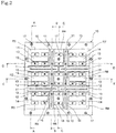
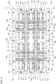
- Fig. 2 is a top view of a configuration of a base plate provided under the slip table 5 shown in Fig. 1 .
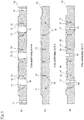
- Figs. 3(a), 3(b), and 3(c) are cross-sectional views of the base plate shown in Fig. 2 taken along lines A-A, B-B, and C-C respectively.
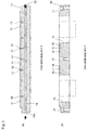
- Figs. 4(a) and 4(b) are cross-sectional views of the base plate shown in Fig. 2 taken along lines D-D and E-E respectively.
- the present invention employs a "fluid bearing system” in which a fluid (e.g., oil; the following description assumes that the fluid is oil) is supplied from a base plate 10 to a bottom face of the slip table 5 so as to form, between the slip table 5 and the base plate 10, an oil film supporting the slip table 5.
- a fluid e.g., oil; the following description assumes that the fluid is oil
- the base plate 10 includes distribution grooves 11 to distribute oil on the base plate 10, for example, two in the lengthwise direction and two in the widthwise direction. Each of the two lengthwise extending distribution grooves 11 is cut in the middle.
- the four distribution grooves 11 thus divide the base plate 10 into nine horizontal regions, which are referred to as regions R1 to R9 for convenience.
- the base plate 10 may be divided into any number of regions other than nine by increasing or decreasing the number of the distribution grooves 11, depending on the size of the base plate 10.
- each ejection hole 13 is located inside a corresponding one of the pockets 12 to eject oil.
- an element hole 14 between each pair of the pockets 12 that are adjacent in the widthwise direction of the base plate 10.
- a flow-passage-forming element is inserted into the element hole 14 as will be described later in detail.
- oil is supplied through fluid flow passages 18 to the ejection holes 13 and the pockets 12.
- the fluid flow passages 18 are formed in the lengthwise direction in Fig. 2 .
- an oil inlet port 18a at a starting end of each fluid flow passage 18 and an oil plug 19 at a terminating end thereof.
- a collecting groove 15 in each region R1 to R3 and R7 to R9 of the base plate 10 in such a manner that both the starting and terminating ends thereof can reach a peripheral edge of the base plate 10.
- a collecting groove 16 across regions R4 to R6 in such a manner that both the starting and terminating ends thereof can reach a peripheral edge of the base plate 10.
- the collecting grooves 15 and 16 are intended to collect oil and flow it to the oil recycling section 7 ( Fig. 1 ).
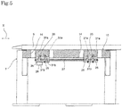
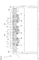
- Figs. 5 and 6 are partial vertical cross-sectional views of the base plate 10 sustained in an upper part of the oil recycling section 7.
- Fig. 7 is an enlarged view of a major part shown in Fig. 6 .
- Fig. 5 is a vertical cross-sectional view of the base plate 10 shown in Fig. 2 taken in the lengthwise direction across regions R2, R5, and R8 and also that Fig. 6 is a vertical cross-sectional view of the base plate 10 shown in Fig. 2 taken in the widthwise direction across regions R1, R2, and R3.
- first flow-passage-forming elements 20 are inserted into the element holes 14. Each first flow-passage-forming element 20 has a top part thereof fixed to the slip table 5. Inside the first flow-passage-forming element 20 are there formed fluid flow passages 25 in communication with ejection holes 31b. The ejection holes 31b are in communication with pockets 31a (details will be given later). Still referring to Fig. 5 , the fluid flow passages 25 in the left-hand first flow-passage-forming element 20 are connected to an inlet section 26 for delivering oil from the oil recycling section 7. The fluid flow passages 25 in the left-hand first flow-passage-forming element 20 and the fluid flow passages 25 in the right-hand first flow-passage-forming element 20 are connected via a fluid flow passage 27.
- the base plate 10 when viewed in a vertical cross-sectional view, includes a first base plate structural element 10a, a second base plate structural element 10b, and two third base plate structural elements 10c, 10c.
- the first base plate structural element 10a has each side face thereof adjacent to a side face of a different base plate structural element (in this figure, the second base plate structural element 10b and one of the third base plate structural elements 10c).
- the second base plate structural element 10b has a side face adjacent to one of the side faces of the first base plate structural element 10a and a side face adjacent to one of side faces of another base plate structural element (in this figure, one of the third base plate structural elements 10c).
- the first flow-passage-forming element 20 is disposed between these first and second base plate structural elements 10a and 10b.
- the first flow-passage-forming element 20, as illustrated in Fig. 7 includes a first vertical flow passage 30 and a horizontal flow passage 31.
- the first vertical flow passage 30 supplies oil to a bottom face of the first base plate structural element 10a and a bottom face of the second base plate structural element 10b.
- the horizontal flow passage 31 supplies oil to one of the side faces of the first base plate structural element 10a and a side face of the second base plate structural element 10b opposite this one of the side faces of the first base plate structural element 10a.
- the first vertical flow passage 30 has downstream ends thereof in communication with ejection holes 30b that are in turn in communication with pockets 30a.
- the horizontal flow passage 31 has downstream ends thereof in communication with the ejection holes 31b (which are in turn in communication with the pockets 31a).
- the oil delivered via the first vertical flow passage 30 is ejected vertically from the ejection holes 30b to form oil films in the pockets 30a.
- These oil films stably support the first base plate structural element 10a and the second base plate structural element 10b in a heightwise direction thereof.
- the oil delivered via the horizontal flow passage 31 is ejected horizontally from the ejection holes 31b to form oil films in the pockets 31a.
- These oil films stably support the first base plate structural element 10a and the second base plate structural element 10b in a widthwise direction thereof.
- the configuration reduces vertical and widthwise vibrations of the first base plate structural element 10a and the second base plate structural element 10b.
- the positions of the first base plate structural element 10a and the second base plate structural element 10b relative to the slip table 5 become stable, which improves precision in the first base plate structural element 10a and the second base plate structural element 10b supporting the slip table 5.
- Oil is ejected at a pressure of, for example, 6 MPa to 7 MPa from the first vertical flow passage 30 and the horizontal flow passage 31.
- the oil ejected vertically from a left-hand and a right-hand second flow-passage-forming element 21 in Fig. 6 has the same effects as the oil ejected vertically from the first flow-passage-forming element 20.
- the first flow-passage-forming elements 20 each including the first vertical flow passage 30 and the horizontal flow passage 31 may be manufactured in the form of a manifold integral to the single base plate 10. This configuration can remarkably simplify the fluid bearing structure over the conventional vibration generator that includes a plurality of base plates constructed as individual units. The configuration therefore allows for low-cost vibration generators.
- each second flow-passage-forming element 21 is provided between the third base plate structural elements 10c and the first and second base plate structural elements 10a and 10b.
- Each second flow-passage-forming element 21 includes a second vertical flow passage 32 that supplies oil to a bottom face of the third base plate structural element 10c and the aforementioned bottom face of the first or second base plate structural element 10a or 10b.
- the fluid delivered via the second vertical flow passages 32 is supplied to these bottom faces of the third base plate structural elements 10c, the first base plate structural element 10a, and the second base plate structural element 10b to form oil films.
- These oil films stably support the first base plate structural element 10a, the second base plate structural element 10b, and the third base plate structural elements 10c in a heightwise direction thereof.
- a negligible vibrating force acts in the widthwise direction (in the top view of the slip table 5) when compared with the vibrating force acting in vibrating direction X (lengthwise direction in the top view of the slip table 5).
- the second flow-passage-forming elements 21 do not need to be supported widthwise by the first, second, and third base plate structural elements 10a, 10b, and 10c.
- the second flow-passage-forming elements 21 only need to be separated from the first, second, and third base plate structural elements 10a, 10b, and 10c by a small gap so as to allow the inserting of the second flow-passage-forming elements 21.
- This configuration can simplify the fluid bearing structure and obviate the need for high precision positioning in the case where horizontal flow passages are provided. The configuration therefore allows for further cost reduction.
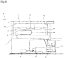
- Fig. 8 is a schematic view of a configuration of the oil recycling section 7.
- the present invention is capable of recycling the oil used to achieve the fluid bearing function.
- the oil recycling section 7, as illustrated in Fig. 8 includes a suction filter 40, a pump 41, a relief valve 42, a switching valve 43, a tubular flow passage 44 connected to, for example, the inlet section 26 and the oil inlet port 18a for the base plate 10, and an oil tank (not shown) where oil falling from the base plate 10 is collected.
- the oil collected in the oil tank after being filtered through the suction filter 40, is pumped up by the pump 41, passed through the relief valve 42 and the switching valve 43, and delivered via the tubular flow passage 44 to the inlet section 26.
- the base plate 10 is divided into nine regions R1 to R9 in the above-described embodiment.
- the present invention is by no means limited to this arrangement.
- the base plate 10 may be divided into 8 or fewer regions or 10 or more regions.
- the following will, in reference to Figs. 9 to 11 , describe variation examples of the above embodiment in which the base plate includes a single region (the base plate is in actuality not divided at all) and is divided into 2 and 15 regions.
- a base plate 110 in accordance with the present variation example includes only one region R10 (the base plate 110 is in actuality not divided at all) and has no collecting grooves for collecting oil and flowing it to an oil recycling section (not shown).
- a slip table (not shown) slightly smaller than the base plate 110.
- a first flow-passage-forming element (not shown) similar to those in the above-described embodiment is inserted in an element hole 114.
- the first flow-passage-forming element (not shown) has a top part thereof fixed to the slip table (not shown).
- Reference numerals 112, 113, 114, and 117 indicate the same members as reference numerals 12, 13, 14, and 17 respectively in the above-described embodiment, and detailed description of these members is omitted for this reason.
- the other members for a vibration generator in accordance with the present variation example are configured as in the above-described embodiment, but may be changed in size and shape in a suitable manner depending on the size and shape of the base plate 110.
- the vibration generator in accordance with the present variation example, including the base plate 110, is capable of achieving functions and effects similar to those achieved by the vibration generator 1 in accordance with the above-described embodiment.
- a base plate 210 in accordance with the present variation example is divided into regions R21 and R22.
- a slip table (not shown) slightly smaller than the base plate 210.
- a first flow-passage-forming element (not shown) similar to those in the above-described embodiment is inserted in each element hole 214.
- the first flow-passage-forming element (not shown) has a top part thereof fixed to the slip table (not shown).
- Reference numerals 212, 213, 214, 215, and 217 indicate the same members as reference numerals 12, 13, 14, 15, and 17 respectively in the above-described embodiment, and detailed description of these members is omitted for this reason.
- the other members for a vibration generator in accordance with the present variation example are configured as in the above-described embodiment, but may be changed in size and shape in a suitable manner depending on the size and shape of the base plate 210.
- the vibration generator in accordance with the present variation example, including the base plate 210, is capable of achieving functions and effects similar to those achieved by the vibration generator 1 in accordance with the above-described embodiment.
- a base plate 310 in accordance with the present variation example is divided into regions R31 to R45.
- a slip table (not shown) slightly smaller than the base plate 310.
- a first flow-passage-forming element (not shown) similar to those in the above-described embodiment is inserted in each element hole 314 in regions R32 and R44.
- the first flow-passage-forming element (not shown) has a top part thereof fixed to the slip table (not shown).
- a second flow-passage-forming element (not shown) similar to those in the above-described embodiment is inserted in each element hole 314 in regions R31, R33, R37, R39, R43, and R45.
- the second flow-passage-forming element (not shown) has a top part thereof fixed to the slip table (not shown). Regions R34 to R36 and R40 to R42 are configured similarly to regions 4 to 6 of the base plate 10 in the above-described embodiment. Reference numerals 311 to 317 indicate the same members as reference numerals 11 to 17 respectively in the above-described embodiment, and detailed description of these members is omitted for this reason.
- the other members for a vibration generator in accordance with the present variation example are configured as in the above-described embodiment, but may be changed in size and shape in a suitable manner depending on the size and shape of the base plate 310.
- the vibration generator in accordance with the present variation example, including the base plate 310 is capable of achieving functions and effects similar to those achieved by the vibration generator 1 in accordance with the above-described embodiment.
- the vibration generator in accordance with the present invention can be suitably used in vibration testing of in-vehicle devices and components and other various devices and components.
Landscapes
- Physics & Mathematics (AREA)
- General Physics & Mathematics (AREA)
- Machine Tool Units (AREA)
- Magnetic Bearings And Hydrostatic Bearings (AREA)
Description
- The present invention relates in general to vibration generators used in vibration test systems and the like and in particular to fluid bearing structures for a slip table in such a vibration generator.
- Various vibration generators have been used in conventional vibration testing and other like systems. These vibration generators may be used, for example, in vibration endurance testing conducted to verify that designed and fabricated products (e.g., automobile parts, electronic components, and aircraft parts) can exhibit expected performance in high vibration environments and also in transport and packing testing in which the products are subjected, before being shipped out, to vibration that the products are likely to experience during transport to verify that the products as such can be safely transported.
- Many different types of vibration generators have been developed so far: unbalance mass types that produce vibration by a centrifugal force generated by an eccentric mass (weight) coupled to a rotating motor, hydraulic types using a piston, and cam types built around a cam mechanism. There are also electrodynamic vibration generators that utilize an electromagnetic effect (so-called "Fleming's left-hand rule") that a force acts on a conductor existing in a magnetic field when an electric current flows through the conductor. To briefly explain the operating principles of the electrodynamic vibration generator, a gap is provided in a cylindrical magnetic path, and a drive coil is suspended in the gap by springs so that the coil does not contact the gap. When a DC current flows through an exciting coil in the magnetic path, a magnetic flux is generated, and a DC magnetic field crossing the drive coil at right angles is generated in the gap. A vibration table produces vibration when an AC current flows through the drive coil.
- Some fluid-bearing type vibration testers are proposed that include a vibration generator in which a slip table is sustained by externally supplying a pressurized fluid such as oil (see, for example, Patent Document 1). A fluid-bearing type vibration tester supports a slip table without contact, hence exhibits high vibration precision and low frictional wear, and therefore allows extended product life.
-
- Patent Document 1:
JP 3260756 B US 5343752 A ) - Patent document 2:
JP H 08136392 A - The vibration tester disclosed in Patent Document 1 however includes a vibrating table placed on a structure constructed as a combination of individual units connected via piping. This configuration is inevitably complex and hence costly.
- Accordingly, the present invention has an object of providing a vibration generator that has a simple fluid bearing structure for a slip table and is therefore inexpensive.
-
- (1) The present invention is directed to a vibration generator vibrating a vibration target, the vibration generator including: a slip table to which the vibration target is attached; a base plate provided under the slip table, the base plate including a first base plate structural element and a second base plate structural element adjacent to the first base plate structural element in a vertical cross-sectional view of the base plate; and a flow-passage-forming element provided between the first base plate structural element and the second base plate structural element, the flow-passage-forming element including a flow passage in which a fluid flows, the flow passage in the flow-passage-forming element including a vertical flow passage and a horizontal flow passage, the vertical flow passage supplying the fluid to bottom faces of the first base plate structural element and the second base plate structural element, the horizontal flow passage supplying the fluid to a side face of the first base plate structural element and a side face of the second base plate structural element opposite the side face of the first base plate structural element.
- According to the configuration described in (1) above, a base plate is provided under a slip table. A vibration generator in accordance with the present invention, in a vertical cross-sectional view of the base plate, includes a region including a first base plate structural element and a second base plate structural element. The first base plate structural element has each side face thereof adjacent to a side face of a different base plate structural element. The second base plate structural element has a side face adjacent to one of the side faces of the first base plate structural element and a side face adjacent to one of side faces of another base plate structural element. A flow-passage-forming element is provided between the first base plate structural element and the second base plate structural element. The flow-passage-forming element includes a flow passage in which a fluid such as oil flows. This flow passage includes a vertical flow passage and a horizontal flow passage. The vertical flow passage supplies the fluid to bottom faces of the first base plate structural element and the second base plate structural element. The horizontal flow passage supplies the fluid to one of the side faces of the first base plate structural element and one of the side faces of the second base plate structural element opposite this one of the side faces of the first base plate structural element. In such a configuration, the fluid delivered via the vertical flow passage is supplied to the aforementioned bottom faces of the first base plate structural element and the second base plate structural element, thereby stably supporting the first base plate structural element and the second base plate structural element in a heightwise direction thereof. In addition, the fluid delivered via the horizontal flow passage is supplied to the aforementioned side faces of the first base plate structural element and the second base plate structural element, thereby stably supporting the first base plate structural element and the second base plate structural element in a widthwise direction thereof. In this manner, the configuration reduces vertical and widthwise vibrations of the first base plate structural element and the second base plate structural element. Thus, when the slip table is supported by the fluid supplied from the base plate, the positions of the first base plate structural element and the second base plate structural element relative to the slip table become stable, which improves precision in the first base plate structural element and the second base plate structural element supporting the slip table. Furthermore, the flow-passage-forming element including the vertical flow passage and the horizontal flow passage is manufactured in the form of a manifold integral to the single base plate. This configuration can remarkably simplify a fluid bearing structure for the slip table over the conventional vibration generator that includes a plurality of base plates constructed as individual units. The configuration therefore allows for low-cost vibration generators.
- In the vibration generators described in (1) above, the base plate preferably includes a fluid flow passage supplying the fluid to a bottom face of the slip table.
- According to the configuration described in (2) above, the fluid is supplied to a bottom face of the slip table via the fluid flow passage. Therefore, the slip table can be stably supported by an oil film. This configuration hence reduces vertical vibrations of the slip table.
- In the vibration generator described in (2) above, the base plate preferably has a top face on which there is formed a plurality of distribution grooves configured to distribute on the base plate the fluid ejected from the fluid flow passage.
- According to the configuration described in (3) above, the fluid delivered via the fluid flow passage is distributed on the base plate by a plurality of distribution grooves. This configuration can hence form a large oil film under the bottom face of the slip table, thereby stably supporting the slip table.
- (4) In either of the vibration generators described in (2) and (3) above, the base plate preferably has a top face on which there is formed a plurality of collecting grooves configured to collect the fluid ejected from the fluid flow passage.
- According to the configuration described in (4) above, the fluid ejected from the fluid flow passage can be collected by the plurality of collecting grooves. The configuration hence enables recycling of the collected fluid, thereby reducing running costs.
-
- [
Fig. 1 ]
Fig. 1 is a front view of a configuration of an entire vibration generator in accordance with the present embodiment. - [
Fig. 2 ]
Fig. 2 is a top view of a configuration of a base plate provided under a slip table shown inFig. 1 . - [
Fig. 3 ]
Figs. 3(a), 3(b), and 3(c) are cross-sectional views of the base plate shown inFig. 2 taken along lines A-A, B-B, and C-C respectively. - [
Fig. 4 ]
Figs. 4(a) and 4(b) are cross-sectional views of the base plate shown inFig. 2 taken along lines D-D and E-E respectively. - [
Fig. 5 ]
Fig. 5 is a partial vertical cross-sectional view of the base plate sustained in an upper part of an oil recycling section. - [
Fig. 6 ]
Fig. 6 is another partial vertical cross-sectional view of the base plate sustained in the upper part of the oil recycling section. - [
Fig. 7 ]
Fig. 7 is an enlarged view of a major part shown inFig. 6 . - [
Fig. 8 ]
Fig. 8 is a schematic view of a configuration of the oil recycling section. - [
Fig. 9 ]
Fig. 9 is a top view of a configuration of variation example 1 of the base plate shown inFig. 2 . - [
Fig. 10 ]
Fig. 10 is a top view of a configuration of variation example 2 of the base plate shown inFig. 2 . - [
Fig. 11 ]
Fig. 11 is a top view of a configuration of variation example 3 of the base plate shown inFig. 2 . - The following will describe a vibration generator in accordance with an embodiment of the present invention in reference to
Figs. 1 to 8 . The description will assume, as an example, that the vibration generator in accordance with the present invention is an electrodynamic vibration generator. - A vibration generator 1 in accordance with the present embodiment is capable of producing horizontal vibrations, as well as producing vertical vibrations.
Fig. 1 shows the vibration generator 1 being set up so that the vibration generator 1 can produce horizontal vibrations. The vibration generator 1 can produce vertical vibrations when a yoke (described later in detail) is rotated clockwise by 90°. - Referring to
Fig. 1 , the vibration generator 1 primarily includes ayoke 2, avibration platform 3, afoundation 4 sustaining theyoke 2, a slip table 5, acoupling section 6 coupling the slip table 5 and thevibration platform 3, and anoil recycling section 7 provided under the slip table 5. Theyoke 2 may be suitably made of magnetic materials with high permeability and high mechanical strength including low carbon steels such as SS400. Thevibration platform 3 may be suitably made of non-magnetic metals with high mechanical strength such as aluminum alloys or synthetic resins such as carbon fiber. Arrow X inFig. 1 indicates vibrating directions. - The
yoke 2 includes an exciting coil (not shown) for generating a static magnetic field in theyoke 2 and a drive coil (not shown) for generating vibrations. The drive coil is placed inside a magnetic gap and formed integral to thevibration platform 3. When a DC current flows through the exciting coil, a magnetic circuit (static magnetic field) is produced in theyoke 2 around the exciting coil. When an AC current with a predetermined frequency flows through the drive coil, a force is generated between the static magnetic field generated in the magnetic gap and the AC current flowing through the drive coil. This force vibrates the drive coil in directions perpendicular to the magnetic flux. The vibration of the drive coil in turn vibrates thevibration platform 3, and hence a vibration target attached to the slip table 5, at the frequency of the AC current flowing through the drive coil. -
Fig. 2 is a top view of a configuration of a base plate provided under the slip table 5 shown inFig. 1 .Figs. 3(a), 3(b), and 3(c) are cross-sectional views of the base plate shown inFig. 2 taken along lines A-A, B-B, and C-C respectively.Figs. 4(a) and 4(b) are cross-sectional views of the base plate shown inFig. 2 taken along lines D-D and E-E respectively. - The present invention employs a "fluid bearing system" in which a fluid (e.g., oil; the following description assumes that the fluid is oil) is supplied from a
base plate 10 to a bottom face of the slip table 5 so as to form, between the slip table 5 and thebase plate 10, an oil film supporting the slip table 5. - As illustrated in
Fig. 2 , thebase plate 10 includesdistribution grooves 11 to distribute oil on thebase plate 10, for example, two in the lengthwise direction and two in the widthwise direction. Each of the two lengthwise extendingdistribution grooves 11 is cut in the middle. The fourdistribution grooves 11 thus divide thebase plate 10 into nine horizontal regions, which are referred to as regions R1 to R9 for convenience. Thebase plate 10 may be divided into any number of regions other than nine by increasing or decreasing the number of thedistribution grooves 11, depending on the size of thebase plate 10. - There are provided
pockets 12 and ejection holes 13 in each region R1 to R9 of thebase plate 10. Eachejection hole 13 is located inside a corresponding one of thepockets 12 to eject oil. In regions R1 to R3 and R7 to R9 of thebase plate 10, there is provided anelement hole 14 between each pair of thepockets 12 that are adjacent in the widthwise direction of thebase plate 10. A flow-passage-forming element is inserted into theelement hole 14 as will be described later in detail. Referring toFig. 3(a) , oil is supplied throughfluid flow passages 18 to the ejection holes 13 and thepockets 12. Thefluid flow passages 18 are formed in the lengthwise direction inFig. 2 . As illustrated inFig. 4(a) , there is provided anoil inlet port 18a at a starting end of eachfluid flow passage 18 and anoil plug 19 at a terminating end thereof. - There is also provided a collecting
groove 15 in each region R1 to R3 and R7 to R9 of thebase plate 10 in such a manner that both the starting and terminating ends thereof can reach a peripheral edge of thebase plate 10. In contrast, there is provided a collectinggroove 16 across regions R4 to R6 in such a manner that both the starting and terminating ends thereof can reach a peripheral edge of thebase plate 10. The collectinggrooves Fig. 1 ). There are providedfastening holes 17 along the peripheral edges and the widthwise extending centerline of thebase plate 10. -
Figs. 5 and6 are partial vertical cross-sectional views of thebase plate 10 sustained in an upper part of theoil recycling section 7.Fig. 7 is an enlarged view of a major part shown inFig. 6 . Note thatFig. 5 is a vertical cross-sectional view of thebase plate 10 shown inFig. 2 taken in the lengthwise direction across regions R2, R5, and R8 and also thatFig. 6 is a vertical cross-sectional view of thebase plate 10 shown inFig. 2 taken in the widthwise direction across regions R1, R2, and R3. - Referring to
Fig. 5 , first flow-passage-formingelements 20 are inserted into the element holes 14. Each first flow-passage-formingelement 20 has a top part thereof fixed to the slip table 5. Inside the first flow-passage-formingelement 20 are there formedfluid flow passages 25 in communication withejection holes 31b. The ejection holes 31b are in communication withpockets 31a (details will be given later). Still referring toFig. 5 , thefluid flow passages 25 in the left-hand first flow-passage-formingelement 20 are connected to aninlet section 26 for delivering oil from theoil recycling section 7. Thefluid flow passages 25 in the left-hand first flow-passage-formingelement 20 and thefluid flow passages 25 in the right-hand first flow-passage-formingelement 20 are connected via afluid flow passage 27. - Referring to
Fig. 6 , thebase plate 10, when viewed in a vertical cross-sectional view, includes a first base platestructural element 10a, a second base platestructural element 10b, and two third base platestructural elements structural element 10a has each side face thereof adjacent to a side face of a different base plate structural element (in this figure, the second base platestructural element 10b and one of the third base platestructural elements 10c). The second base platestructural element 10b has a side face adjacent to one of the side faces of the first base platestructural element 10a and a side face adjacent to one of side faces of another base plate structural element (in this figure, one of the third base platestructural elements 10c). - The first flow-passage-forming
element 20 is disposed between these first and second base platestructural elements element 20, as illustrated inFig. 7 , includes a firstvertical flow passage 30 and ahorizontal flow passage 31. The firstvertical flow passage 30 supplies oil to a bottom face of the first base platestructural element 10a and a bottom face of the second base platestructural element 10b. Thehorizontal flow passage 31 supplies oil to one of the side faces of the first base platestructural element 10a and a side face of the second base platestructural element 10b opposite this one of the side faces of the first base platestructural element 10a. The firstvertical flow passage 30 has downstream ends thereof in communication withejection holes 30b that are in turn in communication withpockets 30a. Thehorizontal flow passage 31 has downstream ends thereof in communication with the ejection holes 31b (which are in turn in communication with thepockets 31a). In such a configuration, the oil delivered via the firstvertical flow passage 30 is ejected vertically from the ejection holes 30b to form oil films in thepockets 30a. These oil films stably support the first base platestructural element 10a and the second base platestructural element 10b in a heightwise direction thereof. In addition, the oil delivered via thehorizontal flow passage 31 is ejected horizontally from the ejection holes 31b to form oil films in thepockets 31a. These oil films stably support the first base platestructural element 10a and the second base platestructural element 10b in a widthwise direction thereof. In this manner, the configuration reduces vertical and widthwise vibrations of the first base platestructural element 10a and the second base platestructural element 10b. Thus, the positions of the first base platestructural element 10a and the second base platestructural element 10b relative to the slip table 5 become stable, which improves precision in the first base platestructural element 10a and the second base platestructural element 10b supporting the slip table 5. Oil is ejected at a pressure of, for example, 6 MPa to 7 MPa from the firstvertical flow passage 30 and thehorizontal flow passage 31. The oil ejected vertically from a left-hand and a right-hand second flow-passage-formingelement 21 inFig. 6 has the same effects as the oil ejected vertically from the first flow-passage-formingelement 20. - The first flow-passage-forming
elements 20 each including the firstvertical flow passage 30 and thehorizontal flow passage 31 may be manufactured in the form of a manifold integral to thesingle base plate 10. This configuration can remarkably simplify the fluid bearing structure over the conventional vibration generator that includes a plurality of base plates constructed as individual units. The configuration therefore allows for low-cost vibration generators. - Referring back to
Fig. 6 , the second flow-passage-formingelements 21 are provided between the third base platestructural elements 10c and the first and second base platestructural elements element 21 includes a secondvertical flow passage 32 that supplies oil to a bottom face of the third base platestructural element 10c and the aforementioned bottom face of the first or second base platestructural element vertical flow passages 32 is supplied to these bottom faces of the third base platestructural elements 10c, the first base platestructural element 10a, and the second base platestructural element 10b to form oil films. These oil films stably support the first base platestructural element 10a, the second base platestructural element 10b, and the third base platestructural elements 10c in a heightwise direction thereof. In addition, a negligible vibrating force acts in the widthwise direction (in the top view of the slip table 5) when compared with the vibrating force acting in vibrating direction X (lengthwise direction in the top view of the slip table 5). In view of this, the second flow-passage-formingelements 21 do not need to be supported widthwise by the first, second, and third base platestructural elements elements 21 only need to be separated from the first, second, and third base platestructural elements elements 21. This configuration can simplify the fluid bearing structure and obviate the need for high precision positioning in the case where horizontal flow passages are provided. The configuration therefore allows for further cost reduction. -
Fig. 8 is a schematic view of a configuration of theoil recycling section 7. The present invention is capable of recycling the oil used to achieve the fluid bearing function. More specifically, theoil recycling section 7, as illustrated inFig. 8 , includes asuction filter 40, apump 41, arelief valve 42, a switchingvalve 43, atubular flow passage 44 connected to, for example, theinlet section 26 and theoil inlet port 18a for thebase plate 10, and an oil tank (not shown) where oil falling from thebase plate 10 is collected. In such a configuration, the oil collected in the oil tank, after being filtered through thesuction filter 40, is pumped up by thepump 41, passed through therelief valve 42 and the switchingvalve 43, and delivered via thetubular flow passage 44 to theinlet section 26. - The present invention has been described so far by way of an embodiment in reference to drawings. Specific arrangements should by no means be limited to this embodiment. The scope of the present invention is defined only by the claims and never bound by the description of the embodiment. Therefore, the embodiment may be modified as in the following, without departing from the scope of the present invention.
- The
base plate 10 is divided into nine regions R1 to R9 in the above-described embodiment. The present invention is by no means limited to this arrangement. Alternatively, thebase plate 10 may be divided into 8 or fewer regions or 10 or more regions. The following will, in reference toFigs. 9 to 11 , describe variation examples of the above embodiment in which the base plate includes a single region (the base plate is in actuality not divided at all) and is divided into 2 and 15 regions. - Referring to
Fig. 9 , abase plate 110 in accordance with the present variation example includes only one region R10 (thebase plate 110 is in actuality not divided at all) and has no collecting grooves for collecting oil and flowing it to an oil recycling section (not shown). On thebase plate 110 is there provided a slip table (not shown) slightly smaller than thebase plate 110. A first flow-passage-forming element (not shown) similar to those in the above-described embodiment is inserted in anelement hole 114. The first flow-passage-forming element (not shown) has a top part thereof fixed to the slip table (not shown).Reference numerals reference numerals base plate 110. The vibration generator in accordance with the present variation example, including thebase plate 110, is capable of achieving functions and effects similar to those achieved by the vibration generator 1 in accordance with the above-described embodiment. - Referring to
Fig. 10 , abase plate 210 in accordance with the present variation example is divided into regions R21 and R22. On thebase plate 210 is there provided a slip table (not shown) slightly smaller than thebase plate 210. A first flow-passage-forming element (not shown) similar to those in the above-described embodiment is inserted in eachelement hole 214. The first flow-passage-forming element (not shown) has a top part thereof fixed to the slip table (not shown).Reference numerals reference numerals base plate 210. The vibration generator in accordance with the present variation example, including thebase plate 210, is capable of achieving functions and effects similar to those achieved by the vibration generator 1 in accordance with the above-described embodiment. - Referring to
Fig. 11 , abase plate 310 in accordance with the present variation example is divided into regions R31 to R45. On thebase plate 310 is there provided a slip table (not shown) slightly smaller than thebase plate 310. A first flow-passage-forming element (not shown) similar to those in the above-described embodiment is inserted in eachelement hole 314 in regions R32 and R44. The first flow-passage-forming element (not shown) has a top part thereof fixed to the slip table (not shown). A second flow-passage-forming element (not shown) similar to those in the above-described embodiment is inserted in eachelement hole 314 in regions R31, R33, R37, R39, R43, and R45. The second flow-passage-forming element (not shown) has a top part thereof fixed to the slip table (not shown). Regions R34 to R36 and R40 to R42 are configured similarly toregions 4 to 6 of thebase plate 10 in the above-described embodiment.Reference numerals 311 to 317 indicate the same members asreference numerals 11 to 17 respectively in the above-described embodiment, and detailed description of these members is omitted for this reason. The other members for a vibration generator in accordance with the present variation example are configured as in the above-described embodiment, but may be changed in size and shape in a suitable manner depending on the size and shape of thebase plate 310. The vibration generator in accordance with the present variation example, including thebase plate 310, is capable of achieving functions and effects similar to those achieved by the vibration generator 1 in accordance with the above-described embodiment. - The vibration generator in accordance with the present invention can be suitably used in vibration testing of in-vehicle devices and components and other various devices and components.
-
- 1 Vibration Generator
- 5 Slip Table
- 10, 110, 210, 310 Base Plate
- 10a First Base Plate Structural Element
- 10b Second Base Plate Structural Element
- 10c Third Base Plate Structural Element
- 11 Distribution Groove
- 15, 16, 215, 315, 316 Collecting Groove
- 18 Fluid Flow Passage
- 20 First Flow-passage-forming element
- 21 Second Flow-passage-forming element
- 30 First Vertical Flow Passage
- 31 Horizontal Flow Passage
- 32 Second Vertical Flow Passage
- R1 to R10, R21, R22, R31 to R45 Region
Claims (4)
- A vibration generator (1) vibrating a vibration target, comprising:a slip table (5) to which the vibration target is attached;a base plate (10,110,210,310) provided under the slip table (5), the base plate (10,110,210,310) comprising a first base plate structural element (10a) and a second base plate structural element (10b) adjacent to the first base plate structural element (10a) in a vertical cross-sectional view of the base plate (10,110,210,310); anda flow-passage-forming element (20) provided between the first base plate structural element (10a) and the second base plate structural element (10b), the flow-passage-forming element (20) including a flow passage (18) in which a fluid flows,characterized in that the flow passage (18) in the flow-passage-forming element (20) comprises a vertical flow passage (30) and a horizontal flow passage (31), the vertical flow passage (30) supplying the fluid to bottom faces of the first base plate structural element (10a) and the second base plate structural element (10b), the horizontal flow passage (31) supplying the fluid to a side face of the first base plate structural element (10a) and a side face of the second base plate structural element (10b) opposite the side face of the first base plate structural element (10a).
- The vibration generator (1) according to claim 1, wherein the base plate (10,110,210,310) includes a fluid flow passage (18) supplying the fluid to a bottom face of the slip table (5).
- The vibration generator (1) according to claim 2, wherein the base plate (10,110,210,310) has a top face on which there is formed a plurality of distribution grooves (11) configured to distribute on the base plate (10,110,210,310) the fluid ejected from the fluid flow passage (18).
- The vibration generator (1) according to claim 2 or 3, wherein the base plate (10,110,210,310) has a top face on which there is formed a plurality of collecting grooves (15,16,215,315,316) configured to collect the fluid ejected from the fluid flow passage (18).
Applications Claiming Priority (2)
| Application Number | Priority Date | Filing Date | Title |
|---|---|---|---|
| JP2014088382A JP5766844B1 (en) | 2014-04-22 | 2014-04-22 | Vibration generator |
| PCT/JP2015/059642 WO2015163085A1 (en) | 2014-04-22 | 2015-03-27 | Vibration generator |
Publications (3)
| Publication Number | Publication Date |
|---|---|
| EP3136077A1 EP3136077A1 (en) | 2017-03-01 |
| EP3136077A4 EP3136077A4 (en) | 2017-04-26 |
| EP3136077B1 true EP3136077B1 (en) | 2018-10-31 |
Family
ID=53888024
Family Applications (1)
| Application Number | Title | Priority Date | Filing Date |
|---|---|---|---|
| EP15783012.6A Not-in-force EP3136077B1 (en) | 2014-04-22 | 2015-03-27 | Vibration generator |
Country Status (5)
| Country | Link |
|---|---|
| US (1) | US10156495B2 (en) |
| EP (1) | EP3136077B1 (en) |
| JP (1) | JP5766844B1 (en) |
| TW (1) | TWI539144B (en) |
| WO (1) | WO2015163085A1 (en) |
Families Citing this family (6)
| Publication number | Priority date | Publication date | Assignee | Title |
|---|---|---|---|---|
| CN105715599A (en) * | 2016-02-02 | 2016-06-29 | 北京苏试创博环境可靠性技术有限公司 | Self-balancing oil-way system for simulation experiment platform for anti-vibration performance of mechanical structure |
| CN105716819B (en) * | 2016-02-24 | 2017-12-26 | 华南农业大学 | A kind of apparatus and method for medicine-chest anti-oscillating performance test |
| CN107192526B (en) * | 2016-03-15 | 2020-07-17 | 北京航天希尔测试技术有限公司 | Horizontal vibration test device capable of directly hanging test piece |
| CN111487027A (en) * | 2020-04-30 | 2020-08-04 | 天津航天瑞莱科技有限公司 | Airborne external longitudinal vibration test platform |
| CN113465854A (en) * | 2021-07-19 | 2021-10-01 | 苏州苏试试验集团股份有限公司 | Inverted horizontal sliding table and vibrating device using same |
| JP7851018B2 (en) * | 2022-06-01 | 2026-04-24 | エミック株式会社 | Vibration generator |
Family Cites Families (6)
| Publication number | Priority date | Publication date | Assignee | Title |
|---|---|---|---|---|
| JPS60102651U (en) * | 1983-12-20 | 1985-07-12 | 株式会社 振研 | Vibrator |
| US5343752A (en) | 1992-04-20 | 1994-09-06 | Team Corporation | High frequency vibration test fixture with hydraulic servo valve and piston actuator |
| JP2860745B2 (en) * | 1993-03-22 | 1999-02-24 | アイエムブイ株式会社 | Vibration test equipment |
| JPH08136392A (en) * | 1994-11-08 | 1996-05-31 | Shinken:Kk | Excitation shaft coupling structure of vibration test machine |
| JP4809072B2 (en) * | 2006-02-07 | 2011-11-02 | カヤバ システム マシナリー株式会社 | Vibration table static pressure supply structure |
| CN101487765B (en) * | 2009-02-13 | 2011-07-20 | 苏州苏试试验仪器有限公司 | Three-axial vibration composite testing apparatus |
-
2014
- 2014-04-22 JP JP2014088382A patent/JP5766844B1/en active Active
-
2015
- 2015-03-27 WO PCT/JP2015/059642 patent/WO2015163085A1/en not_active Ceased
- 2015-03-27 US US15/305,897 patent/US10156495B2/en active Active
- 2015-03-27 EP EP15783012.6A patent/EP3136077B1/en not_active Not-in-force
- 2015-04-22 TW TW104112849A patent/TWI539144B/en not_active IP Right Cessation
Non-Patent Citations (1)
| Title |
|---|
| None * |
Also Published As
| Publication number | Publication date |
|---|---|
| US20170052089A1 (en) | 2017-02-23 |
| WO2015163085A1 (en) | 2015-10-29 |
| TW201541066A (en) | 2015-11-01 |
| EP3136077A4 (en) | 2017-04-26 |
| JP5766844B1 (en) | 2015-08-19 |
| US10156495B2 (en) | 2018-12-18 |
| TWI539144B (en) | 2016-06-21 |
| JP2015206728A (en) | 2015-11-19 |
| EP3136077A1 (en) | 2017-03-01 |
Similar Documents
| Publication | Publication Date | Title |
|---|---|---|
| US10156495B2 (en) | Vibration generator | |
| CN105529896B (en) | Linear vibration motor | |
| WO2012113416A3 (en) | Internally exicted synchronous motor comprising a permanent magnet rotor with multiple corrosion protection | |
| US20110163622A1 (en) | Combination Radial/Axial Electromagnetic Actuator | |
| JP6211650B2 (en) | Linear vibration motor | |
| WO2015088973A1 (en) | Two phase gap cooling of an electrical machine | |
| RU2657861C1 (en) | Compressor | |
| CN102889970B (en) | Test method capable of realizing vibration characteristics physical separation of stator and rotor | |
| CN102570680B (en) | Alignment support device for rotor of permanent-magnetic wind power generator and rotor bearing replacement method | |
| US9683601B2 (en) | Generating radial electromagnetic forces | |
| WO2012123270A3 (en) | Rotor for an electric machine and electric machine | |
| CN105529898B (en) | Linear vibration motor | |
| JP2018514180A (en) | Electric machine and method for dynamically balancing the rotor of the electric machine | |
| US9966817B2 (en) | Electromechanical transducer | |
| CN208589899U (en) | Linear vibration electric motor | |
| CN104303401A (en) | Rotating electrical machine | |
| CN216665948U (en) | Water machine disconnect-type booster pump | |
| CN208589900U (en) | Linear vibration electric motor | |
| Lan et al. | Influence of dummy slots on noise and vibration performance in permanent magnet synchronous machines | |
| Bruchholz | Geometry of space-time | |
| CN104260902B (en) | Satellite sensitive load system and magnetic suspension nonlinear isolation device thereof and method for designing | |
| KR20180076664A (en) | Electromagnetic Filter and manufacturing method thereof | |
| CN209638011U (en) | Water pump with split type structure | |
| CN104014482A (en) | Vibrating screen with socket-type mounted long motor | |
| CN205341213U (en) | Mechanical oscillation platform of multiple vibration form |
Legal Events
| Date | Code | Title | Description |
|---|---|---|---|
| STAA | Information on the status of an ep patent application or granted ep patent |
Free format text: STATUS: THE INTERNATIONAL PUBLICATION HAS BEEN MADE |
|
| PUAI | Public reference made under article 153(3) epc to a published international application that has entered the european phase |
Free format text: ORIGINAL CODE: 0009012 |
|
| STAA | Information on the status of an ep patent application or granted ep patent |
Free format text: STATUS: REQUEST FOR EXAMINATION WAS MADE |
|
| 17P | Request for examination filed |
Effective date: 20161024 |
|
| AK | Designated contracting states |
Kind code of ref document: A1 Designated state(s): AL AT BE BG CH CY CZ DE DK EE ES FI FR GB GR HR HU IE IS IT LI LT LU LV MC MK MT NL NO PL PT RO RS SE SI SK SM TR |
|
| AX | Request for extension of the european patent |
Extension state: BA ME |
|
| A4 | Supplementary search report drawn up and despatched |
Effective date: 20170324 |
|
| RIC1 | Information provided on ipc code assigned before grant |
Ipc: G01M 7/02 20060101AFI20170320BHEP |
|
| DAV | Request for validation of the european patent (deleted) | ||
| DAX | Request for extension of the european patent (deleted) | ||
| GRAP | Despatch of communication of intention to grant a patent |
Free format text: ORIGINAL CODE: EPIDOSNIGR1 |
|
| STAA | Information on the status of an ep patent application or granted ep patent |
Free format text: STATUS: GRANT OF PATENT IS INTENDED |
|
| INTG | Intention to grant announced |
Effective date: 20180703 |
|
| GRAS | Grant fee paid |
Free format text: ORIGINAL CODE: EPIDOSNIGR3 |
|
| GRAA | (expected) grant |
Free format text: ORIGINAL CODE: 0009210 |
|
| STAA | Information on the status of an ep patent application or granted ep patent |
Free format text: STATUS: THE PATENT HAS BEEN GRANTED |
|
| AK | Designated contracting states |
Kind code of ref document: B1 Designated state(s): AL AT BE BG CH CY CZ DE DK EE ES FI FR GB GR HR HU IE IS IT LI LT LU LV MC MK MT NL NO PL PT RO RS SE SI SK SM TR |
|
| REG | Reference to a national code |
Ref country code: CH Ref legal event code: EP Ref country code: GB Ref legal event code: FG4D |
|
| REG | Reference to a national code |
Ref country code: AT Ref legal event code: REF Ref document number: 1059967 Country of ref document: AT Kind code of ref document: T Effective date: 20181115 |
|
| REG | Reference to a national code |
Ref country code: DE Ref legal event code: R096 Ref document number: 602015019227 Country of ref document: DE |
|
| REG | Reference to a national code |
Ref country code: IE Ref legal event code: FG4D |
|
| REG | Reference to a national code |
Ref country code: NL Ref legal event code: MP Effective date: 20181031 |
|
| REG | Reference to a national code |
Ref country code: LT Ref legal event code: MG4D |
|
| REG | Reference to a national code |
Ref country code: AT Ref legal event code: MK05 Ref document number: 1059967 Country of ref document: AT Kind code of ref document: T Effective date: 20181031 |
|
| PG25 | Lapsed in a contracting state [announced via postgrant information from national office to epo] |
Ref country code: ES Free format text: LAPSE BECAUSE OF FAILURE TO SUBMIT A TRANSLATION OF THE DESCRIPTION OR TO PAY THE FEE WITHIN THE PRESCRIBED TIME-LIMIT Effective date: 20181031 Ref country code: LV Free format text: LAPSE BECAUSE OF FAILURE TO SUBMIT A TRANSLATION OF THE DESCRIPTION OR TO PAY THE FEE WITHIN THE PRESCRIBED TIME-LIMIT Effective date: 20181031 Ref country code: FI Free format text: LAPSE BECAUSE OF FAILURE TO SUBMIT A TRANSLATION OF THE DESCRIPTION OR TO PAY THE FEE WITHIN THE PRESCRIBED TIME-LIMIT Effective date: 20181031 Ref country code: LT Free format text: LAPSE BECAUSE OF FAILURE TO SUBMIT A TRANSLATION OF THE DESCRIPTION OR TO PAY THE FEE WITHIN THE PRESCRIBED TIME-LIMIT Effective date: 20181031 Ref country code: HR Free format text: LAPSE BECAUSE OF FAILURE TO SUBMIT A TRANSLATION OF THE DESCRIPTION OR TO PAY THE FEE WITHIN THE PRESCRIBED TIME-LIMIT Effective date: 20181031 Ref country code: PL Free format text: LAPSE BECAUSE OF FAILURE TO SUBMIT A TRANSLATION OF THE DESCRIPTION OR TO PAY THE FEE WITHIN THE PRESCRIBED TIME-LIMIT Effective date: 20181031 Ref country code: BG Free format text: LAPSE BECAUSE OF FAILURE TO SUBMIT A TRANSLATION OF THE DESCRIPTION OR TO PAY THE FEE WITHIN THE PRESCRIBED TIME-LIMIT Effective date: 20190131 Ref country code: IS Free format text: LAPSE BECAUSE OF FAILURE TO SUBMIT A TRANSLATION OF THE DESCRIPTION OR TO PAY THE FEE WITHIN THE PRESCRIBED TIME-LIMIT Effective date: 20190228 Ref country code: AT Free format text: LAPSE BECAUSE OF FAILURE TO SUBMIT A TRANSLATION OF THE DESCRIPTION OR TO PAY THE FEE WITHIN THE PRESCRIBED TIME-LIMIT Effective date: 20181031 Ref country code: NO Free format text: LAPSE BECAUSE OF FAILURE TO SUBMIT A TRANSLATION OF THE DESCRIPTION OR TO PAY THE FEE WITHIN THE PRESCRIBED TIME-LIMIT Effective date: 20190131 |
|
| PG25 | Lapsed in a contracting state [announced via postgrant information from national office to epo] |
Ref country code: NL Free format text: LAPSE BECAUSE OF FAILURE TO SUBMIT A TRANSLATION OF THE DESCRIPTION OR TO PAY THE FEE WITHIN THE PRESCRIBED TIME-LIMIT Effective date: 20181031 Ref country code: RS Free format text: LAPSE BECAUSE OF FAILURE TO SUBMIT A TRANSLATION OF THE DESCRIPTION OR TO PAY THE FEE WITHIN THE PRESCRIBED TIME-LIMIT Effective date: 20181031 Ref country code: PT Free format text: LAPSE BECAUSE OF FAILURE TO SUBMIT A TRANSLATION OF THE DESCRIPTION OR TO PAY THE FEE WITHIN THE PRESCRIBED TIME-LIMIT Effective date: 20190301 Ref country code: GR Free format text: LAPSE BECAUSE OF FAILURE TO SUBMIT A TRANSLATION OF THE DESCRIPTION OR TO PAY THE FEE WITHIN THE PRESCRIBED TIME-LIMIT Effective date: 20190201 Ref country code: AL Free format text: LAPSE BECAUSE OF FAILURE TO SUBMIT A TRANSLATION OF THE DESCRIPTION OR TO PAY THE FEE WITHIN THE PRESCRIBED TIME-LIMIT Effective date: 20181031 Ref country code: SE Free format text: LAPSE BECAUSE OF FAILURE TO SUBMIT A TRANSLATION OF THE DESCRIPTION OR TO PAY THE FEE WITHIN THE PRESCRIBED TIME-LIMIT Effective date: 20181031 |
|
| PG25 | Lapsed in a contracting state [announced via postgrant information from national office to epo] |
Ref country code: IT Free format text: LAPSE BECAUSE OF FAILURE TO SUBMIT A TRANSLATION OF THE DESCRIPTION OR TO PAY THE FEE WITHIN THE PRESCRIBED TIME-LIMIT Effective date: 20181031 Ref country code: CZ Free format text: LAPSE BECAUSE OF FAILURE TO SUBMIT A TRANSLATION OF THE DESCRIPTION OR TO PAY THE FEE WITHIN THE PRESCRIBED TIME-LIMIT Effective date: 20181031 Ref country code: DK Free format text: LAPSE BECAUSE OF FAILURE TO SUBMIT A TRANSLATION OF THE DESCRIPTION OR TO PAY THE FEE WITHIN THE PRESCRIBED TIME-LIMIT Effective date: 20181031 |
|
| REG | Reference to a national code |
Ref country code: DE Ref legal event code: R097 Ref document number: 602015019227 Country of ref document: DE |
|
| PG25 | Lapsed in a contracting state [announced via postgrant information from national office to epo] |
Ref country code: SM Free format text: LAPSE BECAUSE OF FAILURE TO SUBMIT A TRANSLATION OF THE DESCRIPTION OR TO PAY THE FEE WITHIN THE PRESCRIBED TIME-LIMIT Effective date: 20181031 Ref country code: EE Free format text: LAPSE BECAUSE OF FAILURE TO SUBMIT A TRANSLATION OF THE DESCRIPTION OR TO PAY THE FEE WITHIN THE PRESCRIBED TIME-LIMIT Effective date: 20181031 Ref country code: SK Free format text: LAPSE BECAUSE OF FAILURE TO SUBMIT A TRANSLATION OF THE DESCRIPTION OR TO PAY THE FEE WITHIN THE PRESCRIBED TIME-LIMIT Effective date: 20181031 Ref country code: RO Free format text: LAPSE BECAUSE OF FAILURE TO SUBMIT A TRANSLATION OF THE DESCRIPTION OR TO PAY THE FEE WITHIN THE PRESCRIBED TIME-LIMIT Effective date: 20181031 |
|
| PLBE | No opposition filed within time limit |
Free format text: ORIGINAL CODE: 0009261 |
|
| STAA | Information on the status of an ep patent application or granted ep patent |
Free format text: STATUS: NO OPPOSITION FILED WITHIN TIME LIMIT |
|
| 26N | No opposition filed |
Effective date: 20190801 |
|
| PG25 | Lapsed in a contracting state [announced via postgrant information from national office to epo] |
Ref country code: SI Free format text: LAPSE BECAUSE OF FAILURE TO SUBMIT A TRANSLATION OF THE DESCRIPTION OR TO PAY THE FEE WITHIN THE PRESCRIBED TIME-LIMIT Effective date: 20181031 Ref country code: MC Free format text: LAPSE BECAUSE OF FAILURE TO SUBMIT A TRANSLATION OF THE DESCRIPTION OR TO PAY THE FEE WITHIN THE PRESCRIBED TIME-LIMIT Effective date: 20181031 |
|
| REG | Reference to a national code |
Ref country code: CH Ref legal event code: PL |
|
| PG25 | Lapsed in a contracting state [announced via postgrant information from national office to epo] |
Ref country code: LU Free format text: LAPSE BECAUSE OF NON-PAYMENT OF DUE FEES Effective date: 20190327 |
|
| REG | Reference to a national code |
Ref country code: BE Ref legal event code: MM Effective date: 20190331 |
|
| PG25 | Lapsed in a contracting state [announced via postgrant information from national office to epo] |
Ref country code: CH Free format text: LAPSE BECAUSE OF NON-PAYMENT OF DUE FEES Effective date: 20190331 Ref country code: LI Free format text: LAPSE BECAUSE OF NON-PAYMENT OF DUE FEES Effective date: 20190331 Ref country code: IE Free format text: LAPSE BECAUSE OF NON-PAYMENT OF DUE FEES Effective date: 20190327 |
|
| PG25 | Lapsed in a contracting state [announced via postgrant information from national office to epo] |
Ref country code: BE Free format text: LAPSE BECAUSE OF NON-PAYMENT OF DUE FEES Effective date: 20190331 |
|
| PG25 | Lapsed in a contracting state [announced via postgrant information from national office to epo] |
Ref country code: TR Free format text: LAPSE BECAUSE OF FAILURE TO SUBMIT A TRANSLATION OF THE DESCRIPTION OR TO PAY THE FEE WITHIN THE PRESCRIBED TIME-LIMIT Effective date: 20181031 |
|
| PG25 | Lapsed in a contracting state [announced via postgrant information from national office to epo] |
Ref country code: MT Free format text: LAPSE BECAUSE OF NON-PAYMENT OF DUE FEES Effective date: 20190327 |
|
| PG25 | Lapsed in a contracting state [announced via postgrant information from national office to epo] |
Ref country code: CY Free format text: LAPSE BECAUSE OF FAILURE TO SUBMIT A TRANSLATION OF THE DESCRIPTION OR TO PAY THE FEE WITHIN THE PRESCRIBED TIME-LIMIT Effective date: 20181031 |
|
| PG25 | Lapsed in a contracting state [announced via postgrant information from national office to epo] |
Ref country code: HU Free format text: LAPSE BECAUSE OF FAILURE TO SUBMIT A TRANSLATION OF THE DESCRIPTION OR TO PAY THE FEE WITHIN THE PRESCRIBED TIME-LIMIT; INVALID AB INITIO Effective date: 20150327 |
|
| PG25 | Lapsed in a contracting state [announced via postgrant information from national office to epo] |
Ref country code: MK Free format text: LAPSE BECAUSE OF FAILURE TO SUBMIT A TRANSLATION OF THE DESCRIPTION OR TO PAY THE FEE WITHIN THE PRESCRIBED TIME-LIMIT Effective date: 20181031 |
|
| PGFP | Annual fee paid to national office [announced via postgrant information from national office to epo] |
Ref country code: FR Payment date: 20231228 Year of fee payment: 10 |
|
| PGFP | Annual fee paid to national office [announced via postgrant information from national office to epo] |
Ref country code: DE Payment date: 20240331 Year of fee payment: 10 Ref country code: GB Payment date: 20240101 Year of fee payment: 10 |
|
| REG | Reference to a national code |
Ref country code: DE Ref legal event code: R119 Ref document number: 602015019227 Country of ref document: DE |
|
| GBPC | Gb: european patent ceased through non-payment of renewal fee |
Effective date: 20250327 |
|
| PG25 | Lapsed in a contracting state [announced via postgrant information from national office to epo] |
Ref country code: DE Free format text: LAPSE BECAUSE OF NON-PAYMENT OF DUE FEES Effective date: 20251001 |
|
| PG25 | Lapsed in a contracting state [announced via postgrant information from national office to epo] |
Ref country code: GB Free format text: LAPSE BECAUSE OF NON-PAYMENT OF DUE FEES Effective date: 20250327 |
|
| PG25 | Lapsed in a contracting state [announced via postgrant information from national office to epo] |
Ref country code: FR Free format text: LAPSE BECAUSE OF NON-PAYMENT OF DUE FEES Effective date: 20250331 |