EP3135974A1 - Pipe connection fitting - Google Patents
Pipe connection fitting Download PDFInfo
- Publication number
- EP3135974A1 EP3135974A1 EP16186268.5A EP16186268A EP3135974A1 EP 3135974 A1 EP3135974 A1 EP 3135974A1 EP 16186268 A EP16186268 A EP 16186268A EP 3135974 A1 EP3135974 A1 EP 3135974A1
- Authority
- EP
- European Patent Office
- Prior art keywords
- ring
- flap
- tabs
- grip
- terminal
- Prior art date
- Legal status (The legal status is an assumption and is not a legal conclusion. Google has not performed a legal analysis and makes no representation as to the accuracy of the status listed.)
- Granted
Links
Images



Classifications
-
- F—MECHANICAL ENGINEERING; LIGHTING; HEATING; WEAPONS; BLASTING
- F16—ENGINEERING ELEMENTS AND UNITS; GENERAL MEASURES FOR PRODUCING AND MAINTAINING EFFECTIVE FUNCTIONING OF MACHINES OR INSTALLATIONS; THERMAL INSULATION IN GENERAL
- F16L—PIPES; JOINTS OR FITTINGS FOR PIPES; SUPPORTS FOR PIPES, CABLES OR PROTECTIVE TUBING; MEANS FOR THERMAL INSULATION IN GENERAL
- F16L23/00—Flanged joints
- F16L23/16—Flanged joints characterised by the sealing means
- F16L23/18—Flanged joints characterised by the sealing means the sealing means being rings
-
- F—MECHANICAL ENGINEERING; LIGHTING; HEATING; WEAPONS; BLASTING
- F16—ENGINEERING ELEMENTS AND UNITS; GENERAL MEASURES FOR PRODUCING AND MAINTAINING EFFECTIVE FUNCTIONING OF MACHINES OR INSTALLATIONS; THERMAL INSULATION IN GENERAL
- F16L—PIPES; JOINTS OR FITTINGS FOR PIPES; SUPPORTS FOR PIPES, CABLES OR PROTECTIVE TUBING; MEANS FOR THERMAL INSULATION IN GENERAL
- F16L23/00—Flanged joints
- F16L23/02—Flanged joints the flanges being connected by members tensioned axially
- F16L23/024—Flanged joints the flanges being connected by members tensioned axially characterised by how the flanges are joined to, or form an extension of, the pipes
- F16L23/028—Flanged joints the flanges being connected by members tensioned axially characterised by how the flanges are joined to, or form an extension of, the pipes the flanges being held against a shoulder
- F16L23/0286—Flanged joints the flanges being connected by members tensioned axially characterised by how the flanges are joined to, or form an extension of, the pipes the flanges being held against a shoulder the shoulder not being formed from the pipe
-
- F—MECHANICAL ENGINEERING; LIGHTING; HEATING; WEAPONS; BLASTING
- F16—ENGINEERING ELEMENTS AND UNITS; GENERAL MEASURES FOR PRODUCING AND MAINTAINING EFFECTIVE FUNCTIONING OF MACHINES OR INSTALLATIONS; THERMAL INSULATION IN GENERAL
- F16L—PIPES; JOINTS OR FITTINGS FOR PIPES; SUPPORTS FOR PIPES, CABLES OR PROTECTIVE TUBING; MEANS FOR THERMAL INSULATION IN GENERAL
- F16L21/00—Joints with sleeve or socket
- F16L21/08—Joints with sleeve or socket with additional locking means
Definitions
- the present application generally relates to a pipe connection fitting and more particularly, but not exclusively, to a flap ring with pivotable tabs configured to control a position of a grip ring in the pipe connection fitting.
- One embodiment of the present application is a unique connection fitting for a pipe.
- Other embodiments include apparatuses, systems, devices, hardware, methods, and combinations for pipe connection systems having a unique connection fitting with a flap ring to control axial placement of one or more components within the fitting.
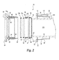
- connection fitting 10 for a pipe 100 is shown therein in an exploded view.
- the connection fitting 10 includes a cylindrically shaped terminal 20 extending between a forward flange 22 at a first end 23 and an aft ring 24 at a second end 25.
- a sloped ramp portion 26 is positioned between the forward flange 22 and the aft ring 24.
- the sloped ramp portion 26 is defined between a first transition region 28 and a second transition region 30.
- the terminal 20 can include a cylindrical portion 36 extending from the forward flange 22 to the first transition region 28.
- the terminal 20 can also include a cylindrical portion 34 extending from the second transition region 30 toward the second end 25.
- One or more connecting ears 32 can be attached to the forward flange 22 and can extend in a radially outward direction. Each connecting ear 32 can include one or more through apertures 33 formed therein.
- a grip ring 40 is configured to secure the fitting 10 to the pipe 100 with a tooth 42 oriented in a circumferential direction around the grip ring 40.
- the tooth 42 is constructed to engage with and penetrate into an outer surface the pipe 100 during installation to hold the pipe connection fitting 10 in a locked position relative to the pipe 100.
- the grip ring 40 is a split ring that includes a gap 44 such that first and second ends 46 and 48 of the grip ring 40 are spaced apart in a free state.
- the terminal 20 forces the ends 46, 48 of the grip ring 40 closer together during installation which causes the tooth 42 to penetrate into the outer surface of the pipe 100.
- the grip ring 40 will be described in further detail below.
- a flap ring 50 is positioned adjacent the grip ring 40 in the assembled pipe connection fitting 10.
- the flap ring 50 includes a first ring portion 52 which can be substantially cylindrical in form.
- a second tapered ring portion 54 extends from the first ring portion 52.
- the second tapered ring portion 54 includes one or more open slots 56 formed therein to define separate segments 57 intermittently spaced around the tapered ring portion 54.
- a plurality of flaps or tabs 58 are positioned to coincide with corresponding slots 56.
- Each tab 58 includes a hinge portion 60 to permit the tab 58 to rotate or pivot thereabout so as to vary from a more radially outward projection to a more radially inward projection.
- a locating flange or shoulder 59 projecting radially outward can be positioned proximate an interface region between the first ring portion 52 and the tapered ring portion 54 of the flap ring 50.
- the pipe connection fitting 10 can include one or more seals 70 (70a, 70b, 70c etc%) and in one form can be an O-ring seal or the like.
- a gasket holder ring 80 is configured to hold one or more of the seals 70 and a portion of the flap ring 40.
- the first cylindrical ring portion 52 of the flap ring 50 can be positioned within the gasket holder ring 80 such that the locating flange 59 is abutted with an end wall 87 of the gasket holder ring 80.
- the gasket holder ring 80 can further include a plurality of ribs 81 projecting inward from an inner surface thereof so as to provide engagement means with the pipe 100.
- a pipe connector 90 for coupling with the terminal 20 can include a connecting flange 92 with ears 94 that corresponds to the connecting ears 32 of the terminal 20 so as to permit connection of the flanges 92, 22 together with one or more threaded fasteners 102 or the like.
- the threaded fasteners 102 can extend through the connecting ears 32 of the forward flange 22 of the terminal 20 and through the opposing connecting ears 94 of the pipe connector 90.
- the fasteners 102 can be tightened via a nut (not shown) or a threaded ear portion as would be known to one skilled in the art to form a locking engagement between the terminal 20 and the pipe connector 90.
- the grip ring 40 includes a forward face 47 (best seen in Fig. 2 ) with a tapered wall 49 extending therefrom.
- the tapered wall 49 of the grip ring 40 extends from a radially outward position proximate the face 47 to a radially inward position distal from the face 47.
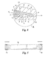
- the circumferential tooth 42 extends radially inward from the grip ring 40 and can be seen with greater cross-section detail in Fig. 4 .
- the terminal 20 includes a substantially cylindrical first portion 36 that transitions proximate the first transition region 28 to a sloped or ramp section 26 projecting radially inward until the ramp section 26 reaches the second transition region 30.
- the second cylindrical guide region 34 extends away from the second transition region 30 to form a guide for the pipe 100.
- the guide region 34 is shown radially outward of the outer diameter 101 of the pipe 100 for clarity, however in some forms the inner diameter of the cylindrical portion 34 can be approximately line to line with the outer diameter 101 of the pipe 100 to keep the terminal 20 concentrically aligned with the pipe 100. In other forms the inner diameter of the cylindrical portion 34 can be greater than a line to line fit with the pipe 100.
- the gasket holder ring 80 includes a landing region 84 to hold one or more seals 70 and at least a portion of the flap ring 50 therein.
- the landing region 84 can include the landing region abutment 85 to position the one or more seals 70b, 70c in a desired location relative to the gasket holder ring 80.
- a portion of the flap ring 50 including the first cylindrical ring portion 52 can be positioned within the landing region 84.
- the locating flange 59 of the flap ring 50 can engage with the end wall 87 of the gasket holder ring 80 to control axial location of the flap ring 50 relative to the gasket holder ring 80.
- a seal groove 82 can be formed in a face 83 of the gasket holder ring 80 such that an additional seal such as an O-ring seal 70a can be positioned in the groove 82 to form a fluid-tight seal between the gasket holder ring 80 and the pipe connector 90.
- a pipe guide portion 86 can be formed on an inner portion of the gasket holder ring 80 such that the outer diameter 101 of the pipe 100 can be substantially in line with the pipe guide 86 in certain embodiments. In other embodiments, the outer diameter 101 can be substantially smaller than the diameter of the guide portion 86.
- a pipe abutment 88 can be formed on the gasket holder ring 80 such that a terminal end 103 of the pipe 100 can engage therewith during installation to define a fixed position of the pipe relative to the gasket holder ring 80.
- FIG. 3 the pipe connection fitting 10 is shown in cross-section in an assembled view.
- a circular portion labeled "A" is enlarged and shown in greater detail in Fig. 4 .
- the sloped ramp portion 26 will engage with the tabs 58 of the flap ring 50 and the grip ring 40 to move and lockingly hold each in a defined position in final installed orientation. This will be described in greater detail below.
- the grip ring 40 includes a circumferential tooth 42 that has a substantially pointed edge 43. This exemplary embodiment illustrates a pointed edge with one angular side wall 41. However, it should be understood that other configurations of edge construction are also contemplated herein.
- the grip ring 40 further includes an inner wall 45 extending between the tooth 42 and an aft end 49 of the grip ring 40.
- the inner wall 45 can be formed in a substantially linear fashion as shown or can have other configurations if desired.
- some portions of the inner wall 45 are positioned away from the outer diameter 101 of the pipe 100 and can extend to a portion of the inner wall 45 proximate to the aft end 49.
- the inner wall 45 at the aft end 49 can be substantially line to line or nominally engaged with the outer diameter 101 of the pipe 100.
- Other configurations of the grip ring 40 are also contemplated herein.
- a sloped outer wall 43 of the grip ring 40 extends between a forward face 47 of the grip ring 40 and the aft end 49.
- the sloped outer wall 43 can include cylindrical portions and/or variable slope angles.
- portions of the slope angle can correspond with the slope angle of an inner wall 112 of the ramp portion 26 of the terminal 20. In other regions the slope may not correspond with the slope angle of portions of the ramp portion 26.
- the terminal 20 can include an outer wall portion 110 and a sloped inner wall portion 112 to define the sloped ramp portion 26.
- the inner sloped wall portion 112 is configured to engage with at least a portion of the sloped outer wall 43 of the grip ring 40 at a final installed position.
- the tab 58 of the flap ring 50 includes an outer sloped wall 61 that can substantially align with a portion of the sloped inner wall 112 of the ramp portion 26 of the terminal 20 in the installed position.
- the inner sloped wall portion 112 causes the flap 58 to rotate about the hinge portion 60 ( Fig. 1 ) in a radially inward direction such that in the final installed position the sloped outer wall 61 of the tab 58 can be aligned with the portion of the sloped inner wall 112 of the flap ring 50.
- the segments 57 of the tapered ring portion 54 and the hinged tabs 58 cooperate to move the grip ring 40 into a desired axial location as the terminal 20 slides over both the grip ring 40 and the flap ring 50 while being connected to the pipe connector 90.
- a face 59 of the tab 58 is positioned adjacent to the forward face 47 of the grip ring 40 in the final installed position.
- sliding movement of the sloped inner wall 112 of the terminal 20 causes the tabs 58 to engage with and move the grip ring 50 as the tabs are forced to rotate downward into a final installed position.
- the position of the grip ring 40 is controlled via engagement of the forward face 47 with the tab face 59 of the tab 58 on one side and engagement with the sloped inner wall 112 on the other side.
- the grip ring 40 may overlap or otherwise engage with the tapered ring portion 54 of the flap ring 50. In other forms the grip ring may be displaced away from the tapered ring portion 57 at the final installed position.
- the final installed position of the grip ring 40 can at least partially define the depth of the penetration of the tooth 42 of the grip ring 40 into the pipe 100 because the axial location thereof defines the engagement location with the sloped inner wall 112 of the terminal 20 which defines the resulting radial displacement of the tooth 42.
- FIGS. 5 through 7 illustrate various configurations for which a pipe connection fitting 10 can be used.
- FIG. 5 illustrates pipe connection fittings 10a and 10b that are displaced from either end of the pipe 100.
- FIG. 6 illustrates the pipe connection fittings installed on opposing ends of the pipe 100.
- FIG. 7 illustrates a configuration wherein elbow pipe connectors 90a, 90b can be connected between pipe fitting connectors 10a, 10b, 10c and 10d.
- a pipe 100 can be inserted through a terminal 20, a grip ring 40, a flap ring 50, and the gasket holder ring 80.
- One or more seals 70 can be are positioned within the gasket holder ring 80 abutment 85 and the flap ring 50 can be located relative to the gasket holder ring 80 via abutment of the shoulder or locating flange 59 of the flap ring 50 with the end wall 87 of the gasket holder ring 80.
- the grip ring 40 can be aligned relative the flap ring 40 such that the gap 44 of the grip ring is circumferentially positioned between adjacent slots 56 of the flap ring 50.
- the grip ring 40 is initially expanded such that the gap 44 of the grip ring 40 is in the most expanded position and may permit the grip ring to slide axially over a portion of the pipe 100 and over segments 57 of the second tapered ring portion 54.
- the tabs 58 are forced to pivot or rotate about the hinged portion 60 into a radially downward direction. This downward rotation of the tabs 58 causes the tabs 58 to engage with and force the grip ring 40 back down the sloped segments 57 of the flap ring 50 if the grip ring 40 was initially in such a location.
- the grip ring 40 is held in a final installed axial position on one side when the tab face 59 is engaged with the forward face 47 of the grip ring 40 and on the other side by the sloped ramp portion 26 of the terminal 20.
- the sloped surface 112 of the inner wall portion of the ramp 26 forces the pointed edge of the tooth 42 to penetrate into the surface of the pipe 100.
- the engaged tooth 42 restricts the entire pipe connection fitting 10 from moving relative to the pipe 100.
- the disclosed pipe connection fitting 10 is operable to control the axial location of the grip ring 40 and thereby the depth of engagement of the tooth 42 with the pipe 100.
- the pipe connection fitting 10 can be installed, disassembled and reinstalled on a pipe 100 without variation of the grip ring 40 relative to the flap ring 50 or variation in the depth of penetration of the tooth 42 into the surface of the pipe 100.
- Position control of the grip ring is desirable because too great of a penetration depth into the wall of the pipe 100 can weaken the pipe wall and result in failure of the pipe 100.
- the grip ring 40 may not hold the connection fitting 100 in position relative to the pipe under certain loading conditions.
- the pipe connection fitting 10 of the present application ensures that a desired tooth penetration can be repeated each time a pipe 100 is connected with the fitting 10.
- Material selection for the pipe connection fitting components, coupling members and other components can include various forms of metals, metal alloys, composites, ceramics, or plastics as desired.
- Metal materials can include, but are not limited to aluminum, steel, iron, super alloys and combinations thereof.
- the metal material may further be formed from cast, wrought, or sheet stock.
- the present disclosure includes pipe connection fitting comprising: a gasket holder ring; a seal positionable within the gasket holder ring; a flap ring having a first ring portion with a plurality of pivotable tabs extending therefrom; a grip ring positionable adjacent the flap ring; and a terminal housing configured to slidingly engage with the gasket holder ring.
- Refining aspects include the flap ring having a second ring portion having a tapered wall extending radially inward from the first ring portion; a locating flange protruding radially outward between the first and second ring portions; and a plurality of slots formed intermittently around the second ring portion; wherein each of the plurality of tabs is positioned proximate a corresponding slot in the second ring portion; wherein each of the plurality of tabs includes a hinge portion extending from the first portion of the flap ring; wherein each of the hinge portions permits pivoting movement of each tab when engaged by the terminal housing during installation; wherein the tabs of the flap ring define an axial abutment for the grip ring; wherein the grip ring is a split ring that terminates at a pair of opposing ends spaced apart from one another in a free state; wherein the grip ring includes a tooth extending radially inward; wherein the tooth extends circumferentially along substantially an entire inner diameter of the grip
- An apparatus comprising: a flap ring configured to control an axial location of a component of a pipe connection fitting; wherein the flap ring comprises: a first ring portion having a substantially cylindrical outer wall diameter; a second ring portion having a tapered outer wall with a decreasing outer diameter projecting from the first ring portion; a plurality of slots formed intermittently around the second ring portion; and a plurality of tabs extending from a hinge connected to the first ring portion, wherein each tab is positioned to correspond with one of the slots in the second ring portion.
- Refining aspects include wherein the hinge permits pivoting movement of the tabs; wherein the tabs project angularly outward from the hinge in a free state; a gasket holder ring constructed to receive the flap ring; and a grip ring positioned adjacent the flap ring; wherein the grip ring is a split ring with a gap between terminal ends; a seal positionable within the gasket holder ring; a terminal having a tapered inner wall; wherein the tapered inner wall of the terminal is constructed to engage with the tabs of the flap ring such that the tabs are pivoted radially inward during sliding movement of the terminal; and wherein the tabs are engageable with the grip ring to control a relative axial position thereof; wherein the grip ring includes a tooth projecting radially inward; wherein the tapered inner wall of the terminal is constructed to engage with the grip ring to control a penetration depth of the tooth into a wall of a pipe.
- Another aspect of the present disclosure includes a method comprising: installing a gasket holder ring on a pipe; positioning a flap ring at least partially within the gasket holder ring, the flap ring including: a first ring portion having a substantially cylindrical wall, a second ring portion having a tapered wall with a decreasing outer diameter projecting from the first portion, a plurality of slots formed intermittently around the second ring portion; a plurality of tabs pivotally connected to the first ring portion and positioned to align with the slots in the second ring portion, and a locator flange positioned between the first and second ring portions constructed to engage with an end wall of the gasket holder ring; positioning a grip ring with a circumferential tooth adjacent the flap ring; sliding a terminal housing over the gasket holder ring; pivoting the plurality of tabs during the sliding of the terminal; and lockingly engaging the tooth of the grip ring with a wall of the pipe as the terminal slides to an installed position.
- Refining aspects include comprising moving the grip ring relative to the tapered wall of the flap ring with the pivoting tabs; wherein the tabs of the flap ring form an abutment to control an axial position between the flap ring and the grip ring; wherein the grip ring is a split ring with a gap between terminal ends; and circumferentially aligning the gap of the split ring between adjacent tabs of the flap ring.
Landscapes
- Engineering & Computer Science (AREA)
- General Engineering & Computer Science (AREA)
- Mechanical Engineering (AREA)
- Quick-Acting Or Multi-Walled Pipe Joints (AREA)
Abstract
Description
- The present application generally relates to a pipe connection fitting and more particularly, but not exclusively, to a flap ring with pivotable tabs configured to control a position of a grip ring in the pipe connection fitting.
- There are a many different types of fittings operable to join pipes together. In some aspects it can be desirable to disassemble a pipe connection fitting from a pipe and reassemble the pipe connection fitting on the same or a different pipe. It can be further desirable to provide a pipe connection fitting that can position components in a defined location such that a fluid tight connection with a pipe can be repeatedly made. Some existing systems have various shortcomings relative to certain applications. Accordingly, there remains a need for further contributions in this area of technology.
- One embodiment of the present application is a unique connection fitting for a pipe. Other embodiments include apparatuses, systems, devices, hardware, methods, and combinations for pipe connection systems having a unique connection fitting with a flap ring to control axial placement of one or more components within the fitting. Further embodiments, forms, features, aspects, benefits, and advantages of the present application shall become apparent from the description and figures provided herewith.
-
-
Fig. 1 is a perspective exploded view of a connection fitting according to one embodiment of the present disclosure; -
Fig. 2 is a cross sectional view of the connection fitting ofFig. 1 ; -
Fig. 3 is a cross sectional view of a portion of the connection fitting ofFig. 2 in an assembled condition; -
Fig. 4 is an enlarged view of a portion ofFig. 3 ; -
Fig. 5 is a side view of a pipe with connection fittings displaced from each end; -
Fig. 6 is a side view ofFig. 5 with connection fittings attached at each end of the pipe; and -
Fig. 7 is a view ofFig. 6 with multiple connection fittings and elbow couplings displaced from each side of the pipe. - For the purposes of promoting an understanding of the principles of the invention, reference will now be made to the embodiments illustrated in the drawings and specific language will be used to describe the same. It will nevertheless be understood that no limitation of the scope of the invention is thereby intended. Any alterations and further modifications in the described embodiments, and any further applications of the principles of the invention as described herein are contemplated as would normally occur to one skilled in the art to which the invention relates.
- Referring generally to
Figs. 1 and2 , a connection fitting 10 for apipe 100 is shown therein in an exploded view. The connection fitting 10 includes a cylindricallyshaped terminal 20 extending between aforward flange 22 at afirst end 23 and anaft ring 24 at asecond end 25. A slopedramp portion 26 is positioned between theforward flange 22 and theaft ring 24. The slopedramp portion 26 is defined between afirst transition region 28 and asecond transition region 30. In one embodiment theterminal 20 can include acylindrical portion 36 extending from theforward flange 22 to thefirst transition region 28. Theterminal 20 can also include acylindrical portion 34 extending from thesecond transition region 30 toward thesecond end 25. One or more connectingears 32 can be attached to theforward flange 22 and can extend in a radially outward direction. Each connectingear 32 can include one or more throughapertures 33 formed therein. - A
grip ring 40 is configured to secure thefitting 10 to thepipe 100 with atooth 42 oriented in a circumferential direction around thegrip ring 40. Thetooth 42 is constructed to engage with and penetrate into an outer surface thepipe 100 during installation to hold the pipe connection fitting 10 in a locked position relative to thepipe 100. Thegrip ring 40 is a split ring that includes agap 44 such that first andsecond ends grip ring 40 are spaced apart in a free state. Theterminal 20 forces theends grip ring 40 closer together during installation which causes thetooth 42 to penetrate into the outer surface of thepipe 100. Thegrip ring 40 will be described in further detail below. - A
flap ring 50 is positioned adjacent thegrip ring 40 in the assembled pipe connection fitting 10. Theflap ring 50 includes afirst ring portion 52 which can be substantially cylindrical in form. A secondtapered ring portion 54 extends from thefirst ring portion 52. The secondtapered ring portion 54 includes one or moreopen slots 56 formed therein to defineseparate segments 57 intermittently spaced around thetapered ring portion 54. A plurality of flaps ortabs 58 are positioned to coincide withcorresponding slots 56. Eachtab 58 includes ahinge portion 60 to permit thetab 58 to rotate or pivot thereabout so as to vary from a more radially outward projection to a more radially inward projection. A locating flange orshoulder 59 projecting radially outward can be positioned proximate an interface region between thefirst ring portion 52 and thetapered ring portion 54 of theflap ring 50. - The pipe connection fitting 10 can include one or more seals 70 (70a, 70b, 70c etc...) and in one form can be an O-ring seal or the like. A
gasket holder ring 80 is configured to hold one or more of theseals 70 and a portion of theflap ring 40. The firstcylindrical ring portion 52 of theflap ring 50 can be positioned within thegasket holder ring 80 such that the locatingflange 59 is abutted with anend wall 87 of thegasket holder ring 80. Thegasket holder ring 80 can further include a plurality ofribs 81 projecting inward from an inner surface thereof so as to provide engagement means with thepipe 100. - A
pipe connector 90 for coupling with theterminal 20 can include a connectingflange 92 withears 94 that corresponds to the connectingears 32 of theterminal 20 so as to permit connection of theflanges fasteners 102 or the like. The threadedfasteners 102 can extend through the connectingears 32 of theforward flange 22 of theterminal 20 and through the opposing connectingears 94 of thepipe connector 90. Thefasteners 102 can be tightened via a nut (not shown) or a threaded ear portion as would be known to one skilled in the art to form a locking engagement between theterminal 20 and thepipe connector 90. - The
grip ring 40 includes a forward face 47 (best seen inFig. 2 ) with atapered wall 49 extending therefrom. Thetapered wall 49 of thegrip ring 40 extends from a radially outward position proximate theface 47 to a radially inward position distal from theface 47. Thecircumferential tooth 42 extends radially inward from thegrip ring 40 and can be seen with greater cross-section detail inFig. 4 . - With particular reference to
Fig. 2 and as described above, theterminal 20 includes a substantially cylindricalfirst portion 36 that transitions proximate thefirst transition region 28 to a sloped orramp section 26 projecting radially inward until theramp section 26 reaches thesecond transition region 30. The secondcylindrical guide region 34 extends away from thesecond transition region 30 to form a guide for thepipe 100. It should be noted that in the view shown inFig. 2 , theguide region 34 is shown radially outward of theouter diameter 101 of thepipe 100 for clarity, however in some forms the inner diameter of thecylindrical portion 34 can be approximately line to line with theouter diameter 101 of thepipe 100 to keep theterminal 20 concentrically aligned with thepipe 100. In other forms the inner diameter of thecylindrical portion 34 can be greater than a line to line fit with thepipe 100. - The
gasket holder ring 80 includes alanding region 84 to hold one ormore seals 70 and at least a portion of theflap ring 50 therein. Thelanding region 84 can include thelanding region abutment 85 to position the one ormore seals gasket holder ring 80. A portion of theflap ring 50 including the firstcylindrical ring portion 52 can be positioned within thelanding region 84. The locatingflange 59 of theflap ring 50 can engage with theend wall 87 of thegasket holder ring 80 to control axial location of theflap ring 50 relative to thegasket holder ring 80. Aseal groove 82 can be formed in aface 83 of thegasket holder ring 80 such that an additional seal such as an O-ring seal 70a can be positioned in thegroove 82 to form a fluid-tight seal between thegasket holder ring 80 and thepipe connector 90. Apipe guide portion 86 can be formed on an inner portion of thegasket holder ring 80 such that theouter diameter 101 of thepipe 100 can be substantially in line with thepipe guide 86 in certain embodiments. In other embodiments, theouter diameter 101 can be substantially smaller than the diameter of theguide portion 86. Apipe abutment 88 can be formed on thegasket holder ring 80 such that aterminal end 103 of thepipe 100 can engage therewith during installation to define a fixed position of the pipe relative to thegasket holder ring 80. - Referring now to
FIG. 3 , the pipe connection fitting 10 is shown in cross-section in an assembled view. A circular portion labeled "A" is enlarged and shown in greater detail inFig. 4 . It can be further understood that as the terminal 20 is urged toward thepipe connector 90, the slopedramp portion 26 will engage with thetabs 58 of theflap ring 50 and thegrip ring 40 to move and lockingly hold each in a defined position in final installed orientation. This will be described in greater detail below. - Referring now to
FIG. 4 , an enlarged view of a portion of the terminal 20, thegrip ring 40 and theflap ring 50 and thepipe 100 is depicted therein. Thegrip ring 40 includes acircumferential tooth 42 that has a substantially pointededge 43. This exemplary embodiment illustrates a pointed edge with oneangular side wall 41. However, it should be understood that other configurations of edge construction are also contemplated herein. Thegrip ring 40 further includes aninner wall 45 extending between thetooth 42 and anaft end 49 of thegrip ring 40. Theinner wall 45 can be formed in a substantially linear fashion as shown or can have other configurations if desired. In this example some portions of theinner wall 45 are positioned away from theouter diameter 101 of thepipe 100 and can extend to a portion of theinner wall 45 proximate to theaft end 49. Theinner wall 45 at theaft end 49 can be substantially line to line or nominally engaged with theouter diameter 101 of thepipe 100. Other configurations of thegrip ring 40 are also contemplated herein. A slopedouter wall 43 of thegrip ring 40 extends between aforward face 47 of thegrip ring 40 and theaft end 49. In one form the slopedouter wall 43 can include cylindrical portions and/or variable slope angles. In some forms, portions of the slope angle can correspond with the slope angle of aninner wall 112 of theramp portion 26 of the terminal 20. In other regions the slope may not correspond with the slope angle of portions of theramp portion 26. - In some forms the terminal 20 can include an
outer wall portion 110 and a slopedinner wall portion 112 to define the slopedramp portion 26. The inner slopedwall portion 112 is configured to engage with at least a portion of the slopedouter wall 43 of thegrip ring 40 at a final installed position. - The
tab 58 of theflap ring 50 includes an outer slopedwall 61 that can substantially align with a portion of the slopedinner wall 112 of theramp portion 26 of the terminal 20 in the installed position. When the terminal 20 is engaged over thegrip ring 40 and theflap ring 50, the inner slopedwall portion 112 causes theflap 58 to rotate about the hinge portion 60 (Fig. 1 ) in a radially inward direction such that in the final installed position the slopedouter wall 61 of thetab 58 can be aligned with the portion of the slopedinner wall 112 of theflap ring 50. Thesegments 57 of the taperedring portion 54 and the hingedtabs 58 cooperate to move thegrip ring 40 into a desired axial location as the terminal 20 slides over both thegrip ring 40 and theflap ring 50 while being connected to thepipe connector 90. Aface 59 of thetab 58 is positioned adjacent to theforward face 47 of thegrip ring 40 in the final installed position. During assembly, sliding movement of the slopedinner wall 112 of the terminal 20 causes thetabs 58 to engage with and move thegrip ring 50 as the tabs are forced to rotate downward into a final installed position. The position of thegrip ring 40 is controlled via engagement of theforward face 47 with thetab face 59 of thetab 58 on one side and engagement with the slopedinner wall 112 on the other side. In a final installed position, thegrip ring 40 may overlap or otherwise engage with the taperedring portion 54 of theflap ring 50. In other forms the grip ring may be displaced away from the taperedring portion 57 at the final installed position. The final installed position of thegrip ring 40 can at least partially define the depth of the penetration of thetooth 42 of thegrip ring 40 into thepipe 100 because the axial location thereof defines the engagement location with the slopedinner wall 112 of the terminal 20 which defines the resulting radial displacement of thetooth 42. -
FIGS. 5 through 7 illustrate various configurations for which a pipe connection fitting 10 can be used.FIG. 5 illustratespipe connection fittings pipe 100.FIG. 6 illustrates the pipe connection fittings installed on opposing ends of thepipe 100.FIG. 7 illustrates a configuration whereinelbow pipe connectors fitting connectors - During installation of the pipe connection fitting 10, a
pipe 100 can be inserted through a terminal 20, agrip ring 40, aflap ring 50, and thegasket holder ring 80. One ormore seals 70 can be are positioned within thegasket holder ring 80abutment 85 and theflap ring 50 can be located relative to thegasket holder ring 80 via abutment of the shoulder or locatingflange 59 of theflap ring 50 with theend wall 87 of thegasket holder ring 80. In one form thegrip ring 40 can be aligned relative theflap ring 40 such that thegap 44 of the grip ring is circumferentially positioned betweenadjacent slots 56 of theflap ring 50. As the terminal 20 slides over thegrip ring 40, thegrip ring 40 is initially expanded such that thegap 44 of thegrip ring 40 is in the most expanded position and may permit the grip ring to slide axially over a portion of thepipe 100 and oversegments 57 of the secondtapered ring portion 54. As the slopedinner wall surface 112 of the terminal 20 slides over thetabs 58, thetabs 58 are forced to pivot or rotate about the hingedportion 60 into a radially downward direction. This downward rotation of thetabs 58 causes thetabs 58 to engage with and force thegrip ring 40 back down the slopedsegments 57 of theflap ring 50 if thegrip ring 40 was initially in such a location. - The
grip ring 40 is held in a final installed axial position on one side when thetab face 59 is engaged with theforward face 47 of thegrip ring 40 and on the other side by the slopedramp portion 26 of the terminal 20. As the terminal continues to slide towards theflange 92, thesloped surface 112 of the inner wall portion of theramp 26 forces the pointed edge of thetooth 42 to penetrate into the surface of thepipe 100. The engagedtooth 42 restricts the entire pipe connection fitting 10 from moving relative to thepipe 100. The disclosed pipe connection fitting 10 is operable to control the axial location of thegrip ring 40 and thereby the depth of engagement of thetooth 42 with thepipe 100. In this manner the pipe connection fitting 10 can be installed, disassembled and reinstalled on apipe 100 without variation of thegrip ring 40 relative to theflap ring 50 or variation in the depth of penetration of thetooth 42 into the surface of thepipe 100. Position control of the grip ring is desirable because too great of a penetration depth into the wall of thepipe 100 can weaken the pipe wall and result in failure of thepipe 100. On the other hand, if the penetration depth of thetooth 42 is too shallow then thegrip ring 40 may not hold the connection fitting 100 in position relative to the pipe under certain loading conditions. The pipe connection fitting 10 of the present application ensures that a desired tooth penetration can be repeated each time apipe 100 is connected with the fitting 10. - Material selection for the pipe connection fitting components, coupling members and other components can include various forms of metals, metal alloys, composites, ceramics, or plastics as desired. Metal materials can include, but are not limited to aluminum, steel, iron, super alloys and combinations thereof. The metal material may further be formed from cast, wrought, or sheet stock.
- In one aspect the present disclosure includes pipe connection fitting comprising: a gasket holder ring; a seal positionable within the gasket holder ring; a flap ring having a first ring portion with a plurality of pivotable tabs extending therefrom; a grip ring positionable adjacent the flap ring; and a terminal housing configured to slidingly engage with the gasket holder ring.
- Refining aspects include the flap ring having a second ring portion having a tapered wall extending radially inward from the first ring portion; a locating flange protruding radially outward between the first and second ring portions; and a plurality of slots formed intermittently around the second ring portion; wherein each of the plurality of tabs is positioned proximate a corresponding slot in the second ring portion; wherein each of the plurality of tabs includes a hinge portion extending from the first portion of the flap ring; wherein each of the hinge portions permits pivoting movement of each tab when engaged by the terminal housing during installation; wherein the tabs of the flap ring define an axial abutment for the grip ring; wherein the grip ring is a split ring that terminates at a pair of opposing ends spaced apart from one another in a free state; wherein the grip ring includes a tooth extending radially inward; wherein the tooth extends circumferentially along substantially an entire inner diameter of the grip ring; wherein the tooth is configured to engage with a surface of a pipe when the terminal is moved to an assembled position; wherein the terminal includes a sloped ramp portion engageable with the tabs of the of the flap ring and the grip ring; and wherein the tabs are pivoted about the hinge when slidingly engaged with the sloped ramp portion during installation of the terminal.
- Another aspect of the present disclosure includes An apparatus comprising: a flap ring configured to control an axial location of a component of a pipe connection fitting; wherein the flap ring comprises: a first ring portion having a substantially cylindrical outer wall diameter; a second ring portion having a tapered outer wall with a decreasing outer diameter projecting from the first ring portion; a plurality of slots formed intermittently around the second ring portion; and a plurality of tabs extending from a hinge connected to the first ring portion, wherein each tab is positioned to correspond with one of the slots in the second ring portion.
- Refining aspects include wherein the hinge permits pivoting movement of the tabs; wherein the tabs project angularly outward from the hinge in a free state; a gasket holder ring constructed to receive the flap ring; and a grip ring positioned adjacent the flap ring; wherein the grip ring is a split ring with a gap between terminal ends; a seal positionable within the gasket holder ring; a terminal having a tapered inner wall; wherein the tapered inner wall of the terminal is constructed to engage with the tabs of the flap ring such that the tabs are pivoted radially inward during sliding movement of the terminal; and wherein the tabs are engageable with the grip ring to control a relative axial position thereof; wherein the grip ring includes a tooth projecting radially inward; wherein the tapered inner wall of the terminal is constructed to engage with the grip ring to control a penetration depth of the tooth into a wall of a pipe.
- Another aspect of the present disclosure includes a method comprising: installing a gasket holder ring on a pipe; positioning a flap ring at least partially within the gasket holder ring, the flap ring including: a first ring portion having a substantially cylindrical wall, a second ring portion having a tapered wall with a decreasing outer diameter projecting from the first portion, a plurality of slots formed intermittently around the second ring portion; a plurality of tabs pivotally connected to the first ring portion and positioned to align with the slots in the second ring portion, and a locator flange positioned between the first and second ring portions constructed to engage with an end wall of the gasket holder ring; positioning a grip ring with a circumferential tooth adjacent the flap ring; sliding a terminal housing over the gasket holder ring; pivoting the plurality of tabs during the sliding of the terminal; and lockingly engaging the tooth of the grip ring with a wall of the pipe as the terminal slides to an installed position.
- Refining aspects include comprising moving the grip ring relative to the tapered wall of the flap ring with the pivoting tabs; wherein the tabs of the flap ring form an abutment to control an axial position between the flap ring and the grip ring; wherein the grip ring is a split ring with a gap between terminal ends; and circumferentially aligning the gap of the split ring between adjacent tabs of the flap ring.
- While the invention has been illustrated and described in detail in the drawings and foregoing description, the same is to be considered as illustrative and not restrictive in character, it being understood that only the preferred embodiments have been shown and described and that all changes and modifications that come within the spirit of the inventions are desired to be protected. It should be understood that while the use of words such as preferable, preferably, preferred or more preferred utilized in the description above indicate that the feature so described may be more desirable, it nonetheless may not be necessary and embodiments lacking the same may be contemplated as within the scope of the invention, the scope being defined by the claims that follow. In reading the claims, it is intended that when words such as "a," "an," "at least one," or "at least one portion" are used there is no intention to limit the claim to only one item unless specifically stated to the contrary in the claim. When the language "at least a portion" and/or "a portion" is used the item can include a portion and/or the entire item unless specifically stated to the contrary.
- Unless specified or limited otherwise, the terms "mounted," "connected," "supported," and "coupled" and variations thereof are used broadly and encompass both direct and indirect mountings, connections, supports, and couplings. Further, "connected" and "coupled" are not restricted to physical or mechanical connections or couplings.
Claims (15)
- A pipe connection fitting comprising:a gasket holder ring;a seal positionable within the gasket holder ring;a flap ring having a first ring portion with a plurality of pivotable tabs extending therefrom;a grip ring positionable adjacent the flap ring; anda terminal housing configured to slidingly engage with the gasket holder ring.
- The pipe connection fitting of claim 1, wherein the flap ring includes:a second ring portion having a tapered wall extending radially inward from the first ring portion;a locating flange protruding radially outward between the first and second ring portions;a plurality of slots formed intermittently around the second ring portion; andwherein each of the plurality of tabs is positioned proximate a corresponding slot in the second ring portion.
- The pipe connection fitting of claim 1, wherein:each of the plurality of tabs includes a hinge portion extending from the first portion of the flap ring; andeach of the hinge portions permits pivoting movement of each tab when engaged by the terminal housing during installation.
- The pipe connection fitting of claim 1, wherein the tabs of the flap ring define an axial abutment for the grip ring.
- The pipe connection fitting of claim 1, wherein the grip ring is a split ring that terminates at a pair of opposing ends spaced apart from one another in a free state.
- The pipe connection fitting of claim 1, wherein:the grip ring includes a tooth extending radially inward; andthe tooth extends circumferentially along substantially an entire inner diameter of the grip ring; andthe tooth is configured to engage with a surface of a pipe when the terminal is moved to an assembled position.
- The pipe connection fitting of claim 1, wherein the terminal includes a sloped ramp portion engageable with the tabs of the of the flap ring and the grip ring; and
wherein the tabs are pivoted about the hinge when slidingly engaged with the sloped ramp portion during installation of the terminal. - An apparatus comprising:a flap ring configured to control an axial location of a component of a pipe connection fitting;wherein the flap ring comprises:a first ring portion having a substantially cylindrical outer wall diameter;a second ring portion having a tapered outer wall with a decreasing outer diameter projecting from the first ring portion;a plurality of slots formed intermittently around the second ring portion; anda plurality of tabs extending from a hinge connected to the first ring portion, wherein each tab is positioned to correspond with one of the slots in the second ring portion.
- The apparatus of claim 8, wherein:the hinge permits pivoting movement of the tabs; andthe tabs project angularly outward from the hinge in a free state.
- The apparatus of claim 8, further comprising:a gasket holder ring constructed to receive the flap ring;a grip ring positioned adjacent the flap ring, wherein the grip ring is defined by a split ring with a gap between terminal ends;a tooth projecting radially inward from the grip ring; anda seal positionable within the gasket holder ring.
- The apparatus of claim 10 further comprising:a terminal having a tapered inner wall;wherein the tapered inner wall of the terminal is constructed to engage with the tabs of the flap ring such that the tabs are pivoted radially inward during sliding movement of the terminal; andwherein the tabs are engageable with the grip ring to control a relative axial position thereof.
- The apparatus of claim 11, wherein the tapered inner wall of the terminal is constructed to engage with the grip ring to control a penetration depth of the tooth into a wall of a pipe.
- A method comprising:installing a gasket holder ring on a pipe;positioning a flap ring at least partially within the gasket holder ring, the flap ring including:a first ring portion having a substantially cylindrical wall, a second ring portion having a tapered wall with a decreasing outer diameter projecting from the first portion, a plurality of slots formed intermittently around the second ring portion; a plurality of tabs pivotally connected to the first ring portion and positioned to align with the slots in the second ring portion, and a locator flange positioned between the first and second ring portions constructed to engage with an end wall of the gasket holder ring;positioning a grip ring adjacent the flap ring, the grip ring defined by a split ring with a gap between terminal ends with a circumferential tooth;sliding a terminal housing over the gasket holder ring;pivoting the plurality of tabs during the sliding of the terminal; andlockingly engaging the tooth of the grip ring with a wall of the pipe as the terminal slides to an installed position.
- The method of claim 13, further comprising moving the grip ring relative to the tapered wall of the flap ring with the pivoting tabs; and
wherein the tabs of the flap ring form an abutment to control an axial position between the flap ring and the grip ring. - The method of claim 13, further comprising circumferentially aligning the gap of the split ring between adjacent tabs of the flap ring.
Applications Claiming Priority (1)
| Application Number | Priority Date | Filing Date | Title |
|---|---|---|---|
| US201562212408P | 2015-08-31 | 2015-08-31 |
Publications (2)
| Publication Number | Publication Date |
|---|---|
| EP3135974A1 true EP3135974A1 (en) | 2017-03-01 |
| EP3135974B1 EP3135974B1 (en) | 2019-08-28 |
Family
ID=56842741
Family Applications (1)
| Application Number | Title | Priority Date | Filing Date |
|---|---|---|---|
| EP16186268.5A Active EP3135974B1 (en) | 2015-08-31 | 2016-08-30 | Pipe connection fitting |
Country Status (2)
| Country | Link |
|---|---|
| US (1) | US10330228B2 (en) |
| EP (1) | EP3135974B1 (en) |
Cited By (1)
| Publication number | Priority date | Publication date | Assignee | Title |
|---|---|---|---|---|
| FR3151367A1 (en) * | 2023-07-20 | 2025-01-24 | Saint-Gobain Pam Canalisation | Corresponding connecting device, packaging assembly, tubular junction and assembly method |
Families Citing this family (3)
| Publication number | Priority date | Publication date | Assignee | Title |
|---|---|---|---|---|
| US20190219207A1 (en) | 2018-01-16 | 2019-07-18 | Rain Bird Corporation | Push To Connect Coupling |
| USD1078947S1 (en) * | 2022-10-13 | 2025-06-10 | Findlay Machine & Tool, Llc | Inlet locking collar for hose reel |
| US12449038B2 (en) * | 2023-05-30 | 2025-10-21 | Contitech Deutschland Gmbh | Compression limiting coupling pilot for composite seal |
Citations (3)
| Publication number | Priority date | Publication date | Assignee | Title |
|---|---|---|---|---|
| US5803513A (en) * | 1996-06-13 | 1998-09-08 | Richardson; Robert J. | Restrained sealed bolted joints of fluid piping systems, inclusive of an improved gland, an added compression control ring, and/or added skid pads placed on a grip ring |
| EP1108176B1 (en) * | 1998-08-24 | 2005-12-14 | PLASSON Ltd | Pipe coupling |
| US20110210543A1 (en) * | 2010-02-26 | 2011-09-01 | Mueller International, Llc | Pipe Coupling Device |
Family Cites Families (31)
| Publication number | Priority date | Publication date | Assignee | Title |
|---|---|---|---|---|
| US2466526A (en) * | 1944-04-08 | 1949-04-05 | Parker Appliance Co | Coupling for tubes |
| US2478149A (en) * | 1944-12-29 | 1949-08-02 | Parker Appliance Co | Coupling for tubes |
| US2398618A (en) * | 1945-01-08 | 1946-04-16 | Parker Appliance Co | Coupling for tubes |
| US2840395A (en) * | 1957-05-06 | 1958-06-24 | Tarnow Nathan | Conduit fitting with spring washer retaining means |
| FR1201165A (en) | 1958-08-07 | 1959-12-29 | Louis Lotigie Ets | Fitting for flexible or semi-rigid plastic pipes, and particularly polyethylene |
| US3389923A (en) * | 1967-11-08 | 1968-06-25 | Haveg Industries Inc | Joint connection |
| US3498647A (en) * | 1967-12-01 | 1970-03-03 | Karl H Schroder | Connector for coaxial tubes or cables |
| FR1574855A (en) | 1968-05-02 | 1969-07-18 | ||
| US4146254A (en) | 1976-03-31 | 1979-03-27 | Bristol Products, Inc. | Coupler for tubing |
| US4073514A (en) * | 1976-05-26 | 1978-02-14 | Indian Head Inc. | Combination pipe fitting and retainer ring |
| US4188051A (en) * | 1977-04-22 | 1980-02-12 | Parker-Hannifin Corporation | Tube coupling |
| US4288105A (en) | 1979-02-21 | 1981-09-08 | Resistoflex Corporation | Pipe union with both pre-load dependent and independent seals |
| US4299413A (en) | 1979-06-26 | 1981-11-10 | Ciba-Geigy Corporation | Pipe coupling |
| US4407526A (en) | 1981-01-05 | 1983-10-04 | Perfection Corporation | Tab-type coupling and method |
| US4568109A (en) | 1983-02-15 | 1986-02-04 | The Dow Chemical Company | Pipe aligning and joining |
| GB2184186A (en) | 1985-11-30 | 1987-06-17 | Tungum Hydraulics Ltd | Improvements in or relating to pipe couplings |
| US5580530A (en) | 1987-07-30 | 1996-12-03 | Johnson & Johnson Medical, Inc. | Device for vapor sterilization of articles having lumens |
| CA2032830C (en) | 1990-12-20 | 1994-07-26 | R.S.T. Instruments Ltd. | Coupling |
| FR2692644B1 (en) | 1992-06-23 | 1995-11-24 | St Mihiel Sa | CRAMPING AND SEALING DEVICE FOR PIPE CONNECTING FLANGES. |
| SE9300365L (en) | 1993-02-05 | 1994-08-01 | Wirsbo Bruks Ab | Method for establishing a pipe connection and for use in the process suitable pipe connection piece |
| GB2300680A (en) | 1994-05-04 | 1996-11-13 | Hepworth Building Prod | Spigot and socket pipe joint with intermediate ring |
| DE69424282T2 (en) | 1994-09-14 | 2000-11-02 | John Derek Guest | Clamping ring |
| US5549334A (en) | 1994-10-20 | 1996-08-27 | Miller Pipeline Corporation | Retaining band assembly for internal pipe seals |
| US5842726A (en) | 1996-02-27 | 1998-12-01 | Smith-Blair, Inc. | Preformed transition pipe coupling |
| JP4264937B2 (en) * | 2003-07-09 | 2009-05-20 | Smc株式会社 | Chuck and fitting |
| CA2459637C (en) * | 2004-02-27 | 2010-04-27 | Masco Canada Limited | Pipe coupling |
| US8205915B1 (en) | 2007-05-25 | 2012-06-26 | Quick Fitting, Inc. | Piping joint assembly system and method |
| US8480134B2 (en) | 2007-05-25 | 2013-07-09 | Quick Fitting, Inc. | Piping joint assembly system and method with sealing ring stabilizer |
| US8474877B2 (en) * | 2007-09-19 | 2013-07-02 | Bridgeport Fittings, Inc. | Push-in fitting for electrical metallic tubing with enhanced sealing and continuity |
| US20090273184A1 (en) | 2008-04-30 | 2009-11-05 | Michael Wright | Self restrained joint for ductile iron pipe and fittings |
| US9901725B2 (en) * | 2012-10-01 | 2018-02-27 | Bayer Healthcare Llc | Overmolded medical connector tubing and method |
-
2016
- 2016-08-29 US US15/250,534 patent/US10330228B2/en active Active
- 2016-08-30 EP EP16186268.5A patent/EP3135974B1/en active Active
Patent Citations (3)
| Publication number | Priority date | Publication date | Assignee | Title |
|---|---|---|---|---|
| US5803513A (en) * | 1996-06-13 | 1998-09-08 | Richardson; Robert J. | Restrained sealed bolted joints of fluid piping systems, inclusive of an improved gland, an added compression control ring, and/or added skid pads placed on a grip ring |
| EP1108176B1 (en) * | 1998-08-24 | 2005-12-14 | PLASSON Ltd | Pipe coupling |
| US20110210543A1 (en) * | 2010-02-26 | 2011-09-01 | Mueller International, Llc | Pipe Coupling Device |
Cited By (1)
| Publication number | Priority date | Publication date | Assignee | Title |
|---|---|---|---|---|
| FR3151367A1 (en) * | 2023-07-20 | 2025-01-24 | Saint-Gobain Pam Canalisation | Corresponding connecting device, packaging assembly, tubular junction and assembly method |
Also Published As
| Publication number | Publication date |
|---|---|
| US20170059068A1 (en) | 2017-03-02 |
| US10330228B2 (en) | 2019-06-25 |
| EP3135974B1 (en) | 2019-08-28 |
Similar Documents
| Publication | Publication Date | Title |
|---|---|---|
| US12276360B2 (en) | Combination sealing member and pipe couplings | |
| US11739869B2 (en) | Coupling gasket with multiple sealing surfaces | |
| US10274115B2 (en) | Coupling with tongue and groove | |
| US10330228B2 (en) | Pipe connection fitting | |
| US10385997B2 (en) | Slip-on coupling gasket | |
| EP2113701B1 (en) | Coupling having angularly oriented cavity | |
| US9194516B2 (en) | Slip-on coupling | |
| CA1095552A (en) | Flareless tube fitting for 37d adapter | |
| US20150076817A1 (en) | Composite sliding gasket for high-pressure joints | |
| EP2952797B1 (en) | Connection joint for pipes to convey gas, compressed air and other fluids | |
| CN100516615C (en) | Fitting | |
| US20190010855A1 (en) | Improved slip joint apparatus and method of use thereof | |
| EP2458251B1 (en) | A composite sliding gasket for high-pressure joints | |
| US20030151251A1 (en) | Furnace pipe connection | |
| EP4168701B1 (en) | Pipe coupling gasket | |
| JP2024056298A (en) | Method of assembling expansion joint and temporary fixing structure for lock ring | |
| HK1098813B (en) | Sealing member for use with pipe couplings | |
| HK1098813A (en) | Sealing member for use with pipe couplings | |
| HK1235100A1 (en) | Connector for pipes | |
| HK1235100B (en) | Connector for pipes |
Legal Events
| Date | Code | Title | Description |
|---|---|---|---|
| PUAI | Public reference made under article 153(3) epc to a published international application that has entered the european phase |
Free format text: ORIGINAL CODE: 0009012 |
|
| STAA | Information on the status of an ep patent application or granted ep patent |
Free format text: STATUS: REQUEST FOR EXAMINATION WAS MADE |
|
| 17P | Request for examination filed |
Effective date: 20160830 |
|
| AK | Designated contracting states |
Kind code of ref document: A1 Designated state(s): AL AT BE BG CH CY CZ DE DK EE ES FI FR GB GR HR HU IE IS IT LI LT LU LV MC MK MT NL NO PL PT RO RS SE SI SK SM TR |
|
| AX | Request for extension of the european patent |
Extension state: BA ME |
|
| STAA | Information on the status of an ep patent application or granted ep patent |
Free format text: STATUS: EXAMINATION IS IN PROGRESS |
|
| 17Q | First examination report despatched |
Effective date: 20180625 |
|
| RIC1 | Information provided on ipc code assigned before grant |
Ipc: F16L 23/028 20060101AFI20190131BHEP Ipc: F16L 23/18 20060101ALI20190131BHEP Ipc: F16L 21/08 20060101ALN20190131BHEP |
|
| GRAP | Despatch of communication of intention to grant a patent |
Free format text: ORIGINAL CODE: EPIDOSNIGR1 |
|
| STAA | Information on the status of an ep patent application or granted ep patent |
Free format text: STATUS: GRANT OF PATENT IS INTENDED |
|
| RIC1 | Information provided on ipc code assigned before grant |
Ipc: F16L 23/028 20060101AFI20190305BHEP Ipc: F16L 23/18 20060101ALI20190305BHEP Ipc: F16L 21/08 20060101ALN20190305BHEP |
|
| INTG | Intention to grant announced |
Effective date: 20190320 |
|
| GRAS | Grant fee paid |
Free format text: ORIGINAL CODE: EPIDOSNIGR3 |
|
| GRAA | (expected) grant |
Free format text: ORIGINAL CODE: 0009210 |
|
| STAA | Information on the status of an ep patent application or granted ep patent |
Free format text: STATUS: THE PATENT HAS BEEN GRANTED |
|
| AK | Designated contracting states |
Kind code of ref document: B1 Designated state(s): AL AT BE BG CH CY CZ DE DK EE ES FI FR GB GR HR HU IE IS IT LI LT LU LV MC MK MT NL NO PL PT RO RS SE SI SK SM TR |
|
| REG | Reference to a national code |
Ref country code: GB Ref legal event code: FG4D |
|
| REG | Reference to a national code |
Ref country code: CH Ref legal event code: EP |
|
| REG | Reference to a national code |
Ref country code: DE Ref legal event code: R096 Ref document number: 602016019292 Country of ref document: DE |
|
| REG | Reference to a national code |
Ref country code: AT Ref legal event code: REF Ref document number: 1172835 Country of ref document: AT Kind code of ref document: T Effective date: 20190915 |
|
| REG | Reference to a national code |
Ref country code: IE Ref legal event code: FG4D |
|
| REG | Reference to a national code |
Ref country code: NL Ref legal event code: MP Effective date: 20190828 |
|
| REG | Reference to a national code |
Ref country code: LT Ref legal event code: MG4D |
|
| PG25 | Lapsed in a contracting state [announced via postgrant information from national office to epo] |
Ref country code: SE Free format text: LAPSE BECAUSE OF FAILURE TO SUBMIT A TRANSLATION OF THE DESCRIPTION OR TO PAY THE FEE WITHIN THE PRESCRIBED TIME-LIMIT Effective date: 20190828 Ref country code: HR Free format text: LAPSE BECAUSE OF FAILURE TO SUBMIT A TRANSLATION OF THE DESCRIPTION OR TO PAY THE FEE WITHIN THE PRESCRIBED TIME-LIMIT Effective date: 20190828 Ref country code: NO Free format text: LAPSE BECAUSE OF FAILURE TO SUBMIT A TRANSLATION OF THE DESCRIPTION OR TO PAY THE FEE WITHIN THE PRESCRIBED TIME-LIMIT Effective date: 20191128 Ref country code: PT Free format text: LAPSE BECAUSE OF FAILURE TO SUBMIT A TRANSLATION OF THE DESCRIPTION OR TO PAY THE FEE WITHIN THE PRESCRIBED TIME-LIMIT Effective date: 20191230 Ref country code: FI Free format text: LAPSE BECAUSE OF FAILURE TO SUBMIT A TRANSLATION OF THE DESCRIPTION OR TO PAY THE FEE WITHIN THE PRESCRIBED TIME-LIMIT Effective date: 20190828 Ref country code: LT Free format text: LAPSE BECAUSE OF FAILURE TO SUBMIT A TRANSLATION OF THE DESCRIPTION OR TO PAY THE FEE WITHIN THE PRESCRIBED TIME-LIMIT Effective date: 20190828 Ref country code: NL Free format text: LAPSE BECAUSE OF FAILURE TO SUBMIT A TRANSLATION OF THE DESCRIPTION OR TO PAY THE FEE WITHIN THE PRESCRIBED TIME-LIMIT Effective date: 20190828 Ref country code: BG Free format text: LAPSE BECAUSE OF FAILURE TO SUBMIT A TRANSLATION OF THE DESCRIPTION OR TO PAY THE FEE WITHIN THE PRESCRIBED TIME-LIMIT Effective date: 20191128 |
|
| PG25 | Lapsed in a contracting state [announced via postgrant information from national office to epo] |
Ref country code: GR Free format text: LAPSE BECAUSE OF FAILURE TO SUBMIT A TRANSLATION OF THE DESCRIPTION OR TO PAY THE FEE WITHIN THE PRESCRIBED TIME-LIMIT Effective date: 20191129 Ref country code: LV Free format text: LAPSE BECAUSE OF FAILURE TO SUBMIT A TRANSLATION OF THE DESCRIPTION OR TO PAY THE FEE WITHIN THE PRESCRIBED TIME-LIMIT Effective date: 20190828 Ref country code: AL Free format text: LAPSE BECAUSE OF FAILURE TO SUBMIT A TRANSLATION OF THE DESCRIPTION OR TO PAY THE FEE WITHIN THE PRESCRIBED TIME-LIMIT Effective date: 20190828 Ref country code: RS Free format text: LAPSE BECAUSE OF FAILURE TO SUBMIT A TRANSLATION OF THE DESCRIPTION OR TO PAY THE FEE WITHIN THE PRESCRIBED TIME-LIMIT Effective date: 20190828 Ref country code: ES Free format text: LAPSE BECAUSE OF FAILURE TO SUBMIT A TRANSLATION OF THE DESCRIPTION OR TO PAY THE FEE WITHIN THE PRESCRIBED TIME-LIMIT Effective date: 20190828 Ref country code: IS Free format text: LAPSE BECAUSE OF FAILURE TO SUBMIT A TRANSLATION OF THE DESCRIPTION OR TO PAY THE FEE WITHIN THE PRESCRIBED TIME-LIMIT Effective date: 20191228 |
|
| REG | Reference to a national code |
Ref country code: AT Ref legal event code: MK05 Ref document number: 1172835 Country of ref document: AT Kind code of ref document: T Effective date: 20190828 |
|
| PG25 | Lapsed in a contracting state [announced via postgrant information from national office to epo] |
Ref country code: TR Free format text: LAPSE BECAUSE OF FAILURE TO SUBMIT A TRANSLATION OF THE DESCRIPTION OR TO PAY THE FEE WITHIN THE PRESCRIBED TIME-LIMIT Effective date: 20190828 |
|
| RAP2 | Party data changed (patent owner data changed or rights of a patent transferred) |
Owner name: INGERSOLL-RAND INDUSTRIAL U.S., INC. |
|
| PG25 | Lapsed in a contracting state [announced via postgrant information from national office to epo] |
Ref country code: PL Free format text: LAPSE BECAUSE OF FAILURE TO SUBMIT A TRANSLATION OF THE DESCRIPTION OR TO PAY THE FEE WITHIN THE PRESCRIBED TIME-LIMIT Effective date: 20190828 Ref country code: RO Free format text: LAPSE BECAUSE OF FAILURE TO SUBMIT A TRANSLATION OF THE DESCRIPTION OR TO PAY THE FEE WITHIN THE PRESCRIBED TIME-LIMIT Effective date: 20190828 Ref country code: DK Free format text: LAPSE BECAUSE OF FAILURE TO SUBMIT A TRANSLATION OF THE DESCRIPTION OR TO PAY THE FEE WITHIN THE PRESCRIBED TIME-LIMIT Effective date: 20190828 Ref country code: AT Free format text: LAPSE BECAUSE OF FAILURE TO SUBMIT A TRANSLATION OF THE DESCRIPTION OR TO PAY THE FEE WITHIN THE PRESCRIBED TIME-LIMIT Effective date: 20190828 Ref country code: EE Free format text: LAPSE BECAUSE OF FAILURE TO SUBMIT A TRANSLATION OF THE DESCRIPTION OR TO PAY THE FEE WITHIN THE PRESCRIBED TIME-LIMIT Effective date: 20190828 Ref country code: IT Free format text: LAPSE BECAUSE OF FAILURE TO SUBMIT A TRANSLATION OF THE DESCRIPTION OR TO PAY THE FEE WITHIN THE PRESCRIBED TIME-LIMIT Effective date: 20190828 |
|
| PG25 | Lapsed in a contracting state [announced via postgrant information from national office to epo] |
Ref country code: LU Free format text: LAPSE BECAUSE OF NON-PAYMENT OF DUE FEES Effective date: 20190830 Ref country code: CH Free format text: LAPSE BECAUSE OF NON-PAYMENT OF DUE FEES Effective date: 20190831 Ref country code: IS Free format text: LAPSE BECAUSE OF FAILURE TO SUBMIT A TRANSLATION OF THE DESCRIPTION OR TO PAY THE FEE WITHIN THE PRESCRIBED TIME-LIMIT Effective date: 20200224 Ref country code: LI Free format text: LAPSE BECAUSE OF NON-PAYMENT OF DUE FEES Effective date: 20190831 Ref country code: SM Free format text: LAPSE BECAUSE OF FAILURE TO SUBMIT A TRANSLATION OF THE DESCRIPTION OR TO PAY THE FEE WITHIN THE PRESCRIBED TIME-LIMIT Effective date: 20190828 Ref country code: SK Free format text: LAPSE BECAUSE OF FAILURE TO SUBMIT A TRANSLATION OF THE DESCRIPTION OR TO PAY THE FEE WITHIN THE PRESCRIBED TIME-LIMIT Effective date: 20190828 Ref country code: CZ Free format text: LAPSE BECAUSE OF FAILURE TO SUBMIT A TRANSLATION OF THE DESCRIPTION OR TO PAY THE FEE WITHIN THE PRESCRIBED TIME-LIMIT Effective date: 20190828 Ref country code: MC Free format text: LAPSE BECAUSE OF FAILURE TO SUBMIT A TRANSLATION OF THE DESCRIPTION OR TO PAY THE FEE WITHIN THE PRESCRIBED TIME-LIMIT Effective date: 20190828 |
|
| REG | Reference to a national code |
Ref country code: BE Ref legal event code: MM Effective date: 20190831 |
|
| REG | Reference to a national code |
Ref country code: DE Ref legal event code: R097 Ref document number: 602016019292 Country of ref document: DE |
|
| PLBE | No opposition filed within time limit |
Free format text: ORIGINAL CODE: 0009261 |
|
| STAA | Information on the status of an ep patent application or granted ep patent |
Free format text: STATUS: NO OPPOSITION FILED WITHIN TIME LIMIT |
|
| PG2D | Information on lapse in contracting state deleted |
Ref country code: IS |
|
| PG25 | Lapsed in a contracting state [announced via postgrant information from national office to epo] |
Ref country code: IE Free format text: LAPSE BECAUSE OF NON-PAYMENT OF DUE FEES Effective date: 20190830 |
|
| 26N | No opposition filed |
Effective date: 20200603 |
|
| PG25 | Lapsed in a contracting state [announced via postgrant information from national office to epo] |
Ref country code: BE Free format text: LAPSE BECAUSE OF NON-PAYMENT OF DUE FEES Effective date: 20190831 Ref country code: SI Free format text: LAPSE BECAUSE OF FAILURE TO SUBMIT A TRANSLATION OF THE DESCRIPTION OR TO PAY THE FEE WITHIN THE PRESCRIBED TIME-LIMIT Effective date: 20190828 |
|
| REG | Reference to a national code |
Ref country code: GB Ref legal event code: 732E Free format text: REGISTERED BETWEEN 20200806 AND 20200812 |
|
| REG | Reference to a national code |
Ref country code: DE Ref legal event code: R082 Ref document number: 602016019292 Country of ref document: DE Representative=s name: HASELTINE LAKE KEMPNER LLP, DE Ref country code: DE Ref legal event code: R081 Ref document number: 602016019292 Country of ref document: DE Owner name: INGERSOLL-RAND INDUSTRIAL U.S., INC. (N.D.GES., US Free format text: FORMER OWNER: INGERSOLL-RAND COMPANY, DAVIDSON, N.C., US Ref country code: DE Ref legal event code: R082 Ref document number: 602016019292 Country of ref document: DE Representative=s name: HL KEMPNER PATENTANWALT, RECHTSANWALT, SOLICIT, DE Ref country code: DE Ref legal event code: R082 Ref document number: 602016019292 Country of ref document: DE Representative=s name: MURGITROYD & COMPANY, DE |
|
| REG | Reference to a national code |
Ref country code: DE Ref legal event code: R082 Ref document number: 602016019292 Country of ref document: DE Representative=s name: MURGITROYD GERMANY PATENTANWALTSGESELLSCHAFT M, DE Ref country code: DE Ref legal event code: R082 Ref document number: 602016019292 Country of ref document: DE Representative=s name: HL KEMPNER PATENTANWALT, RECHTSANWALT, SOLICIT, DE Ref country code: DE Ref legal event code: R082 Ref document number: 602016019292 Country of ref document: DE Representative=s name: MURGITROYD & COMPANY, DE |
|
| REG | Reference to a national code |
Ref country code: DE Ref legal event code: R082 Ref document number: 602016019292 Country of ref document: DE Representative=s name: MURGITROYD GERMANY PATENTANWALTSGESELLSCHAFT M, DE Ref country code: DE Ref legal event code: R082 Ref document number: 602016019292 Country of ref document: DE Representative=s name: MURGITROYD & COMPANY, DE |
|
| PG25 | Lapsed in a contracting state [announced via postgrant information from national office to epo] |
Ref country code: CY Free format text: LAPSE BECAUSE OF FAILURE TO SUBMIT A TRANSLATION OF THE DESCRIPTION OR TO PAY THE FEE WITHIN THE PRESCRIBED TIME-LIMIT Effective date: 20190828 |
|
| PG25 | Lapsed in a contracting state [announced via postgrant information from national office to epo] |
Ref country code: HU Free format text: LAPSE BECAUSE OF FAILURE TO SUBMIT A TRANSLATION OF THE DESCRIPTION OR TO PAY THE FEE WITHIN THE PRESCRIBED TIME-LIMIT; INVALID AB INITIO Effective date: 20160830 Ref country code: MT Free format text: LAPSE BECAUSE OF FAILURE TO SUBMIT A TRANSLATION OF THE DESCRIPTION OR TO PAY THE FEE WITHIN THE PRESCRIBED TIME-LIMIT Effective date: 20190828 |
|
| PG25 | Lapsed in a contracting state [announced via postgrant information from national office to epo] |
Ref country code: MK Free format text: LAPSE BECAUSE OF FAILURE TO SUBMIT A TRANSLATION OF THE DESCRIPTION OR TO PAY THE FEE WITHIN THE PRESCRIBED TIME-LIMIT Effective date: 20190828 |
|
| P01 | Opt-out of the competence of the unified patent court (upc) registered |
Effective date: 20230523 |
|
| PGFP | Annual fee paid to national office [announced via postgrant information from national office to epo] |
Ref country code: DE Payment date: 20250828 Year of fee payment: 10 |
|
| PGFP | Annual fee paid to national office [announced via postgrant information from national office to epo] |
Ref country code: GB Payment date: 20250829 Year of fee payment: 10 |
|
| PGFP | Annual fee paid to national office [announced via postgrant information from national office to epo] |
Ref country code: FR Payment date: 20250828 Year of fee payment: 10 |