EP3135967A1 - Heat exchanging valve arrangement - Google Patents
Heat exchanging valve arrangement Download PDFInfo
- Publication number
- EP3135967A1 EP3135967A1 EP16183766.1A EP16183766A EP3135967A1 EP 3135967 A1 EP3135967 A1 EP 3135967A1 EP 16183766 A EP16183766 A EP 16183766A EP 3135967 A1 EP3135967 A1 EP 3135967A1
- Authority
- EP
- European Patent Office
- Prior art keywords
- passageway
- opening
- heat exchanging
- valve arrangement
- manifold
- Prior art date
- Legal status (The legal status is an assumption and is not a legal conclusion. Google has not performed a legal analysis and makes no representation as to the accuracy of the status listed.)
- Granted
Links
Images

Classifications
-
- F—MECHANICAL ENGINEERING; LIGHTING; HEATING; WEAPONS; BLASTING
- F16—ENGINEERING ELEMENTS AND UNITS; GENERAL MEASURES FOR PRODUCING AND MAINTAINING EFFECTIVE FUNCTIONING OF MACHINES OR INSTALLATIONS; THERMAL INSULATION IN GENERAL
- F16K—VALVES; TAPS; COCKS; ACTUATING-FLOATS; DEVICES FOR VENTING OR AERATING
- F16K49/00—Means in or on valves for heating or cooling
- F16K49/005—Circulation means for a separate heat transfer fluid
- F16K49/007—Circulation means for a separate heat transfer fluid located within the obturating element
-
- B—PERFORMING OPERATIONS; TRANSPORTING
- B64—AIRCRAFT; AVIATION; COSMONAUTICS
- B64D—EQUIPMENT FOR FITTING IN OR TO AIRCRAFT; FLIGHT SUITS; PARACHUTES; ARRANGEMENT OR MOUNTING OF POWER PLANTS OR PROPULSION TRANSMISSIONS IN AIRCRAFT
- B64D13/00—Arrangements or adaptations of air-treatment apparatus for aircraft crew or passengers, or freight space
-
- F—MECHANICAL ENGINEERING; LIGHTING; HEATING; WEAPONS; BLASTING
- F01—MACHINES OR ENGINES IN GENERAL; ENGINE PLANTS IN GENERAL; STEAM ENGINES
- F01D—NON-POSITIVE DISPLACEMENT MACHINES OR ENGINES, e.g. STEAM TURBINES
- F01D17/00—Regulating or controlling by varying flow
- F01D17/10—Final actuators
- F01D17/12—Final actuators arranged in stator parts
- F01D17/14—Final actuators arranged in stator parts varying effective cross-sectional area of nozzles or guide conduits
- F01D17/141—Final actuators arranged in stator parts varying effective cross-sectional area of nozzles or guide conduits by means of shiftable members or valves obturating part of the flow path
- F01D17/145—Final actuators arranged in stator parts varying effective cross-sectional area of nozzles or guide conduits by means of shiftable members or valves obturating part of the flow path by means of valves, e.g. for steam turbines
-
- F—MECHANICAL ENGINEERING; LIGHTING; HEATING; WEAPONS; BLASTING
- F16—ENGINEERING ELEMENTS AND UNITS; GENERAL MEASURES FOR PRODUCING AND MAINTAINING EFFECTIVE FUNCTIONING OF MACHINES OR INSTALLATIONS; THERMAL INSULATION IN GENERAL
- F16K—VALVES; TAPS; COCKS; ACTUATING-FLOATS; DEVICES FOR VENTING OR AERATING
- F16K11/00—Multiple-way valves, e.g. mixing valves; Pipe fittings incorporating such valves
- F16K11/02—Multiple-way valves, e.g. mixing valves; Pipe fittings incorporating such valves with all movable sealing faces moving as one unit
- F16K11/08—Multiple-way valves, e.g. mixing valves; Pipe fittings incorporating such valves with all movable sealing faces moving as one unit comprising only taps or cocks
- F16K11/085—Multiple-way valves, e.g. mixing valves; Pipe fittings incorporating such valves with all movable sealing faces moving as one unit comprising only taps or cocks with cylindrical plug
- F16K11/0853—Multiple-way valves, e.g. mixing valves; Pipe fittings incorporating such valves with all movable sealing faces moving as one unit comprising only taps or cocks with cylindrical plug having all the connecting conduits situated in a single plane perpendicular to the axis of the plug
Definitions
- Valve arrangements such as diverter valves, for example, typically rely upon rotation of a member within a housing to realigned openings in the member with passageways in the housing to alter porting of fluids therethrough.
- These devices serve the purpose for which they were designed. Using such devices in harsh environments that they may not have originally been designed for may affect smooth operation thereof. Alterations to such devices to allow smooth operation in ever more harsh conditions may be of interest to those who practice in the art.
- a heat exchanging valve arrangement that includes, a manifold defining a chamber, a first passageway, a second passageway, a third passageway, and a fourth passageway, and a member movable relative to the manifold configured to define fluidic communication between the first passageway and the second passageway when in a first position and between the first passageway and the third passageway when in a second position, fluid is flowable into the chamber through the fourth passageway such that fluid is exposed to surfaces of the member regardless of whether the member is in the first position or the second position.
- further embodiments include: wherein the member has a first opening, a second opening and a third opening all in fluidic communication with one another and the first opening is aligned with the first passageway, the second opening is aligned with the second passageway and the third opening is aligned with the fourth passageway when the member is in the first position thereby providing fluidic communication between the first passageway and the second passageway through the first opening and the second opening; wherein the first opening is aligned with the fourth passageway, the second opening is aligned with the first passageway and the third opening is aligned with the third passageway when the member is in the second position, thereby providing fluidic communication between the first passageway and the third passageway through the second opening and the third opening; wherein the member defines an inside that fluidically connects the first opening, the second opening and the third opening to one another; wherein walls that define the first opening, the second opening and the third opening also define inner radial features of a plenum, and fluid flowing
- the arrangement includes, a manifold defining multiple passageways, and a member movably disposed within the manifold having an inside fluidically connecting at least three openings and walls defining the at least three openings separating the inside from a plenum also defined within the member, the member is movable between a first position and a second position relative to the manifold, the heat exchanging valve arrangement is also configured such that fluid can enter the inside through a first of the multiple passageways and one of the at least three openings when the member is in the first position and exist the inside through another of the at least three openings and another of the multiple passageways when the member is in the second position, and fluid flowing into the plenum from yet another of the multiple passageways is exposed to the walls prior to mixing with fluid exiting the inside.
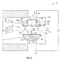
- the arrangement 10 includes, a manifold 14 defining at least one chamber 1 8, a first passageway 21, a second passageway 22, a third passageway 23, and a fourth passageway 24. Also, a member 28 is movable relative to the manifold 14 and configured to define fluidic communication between the first passageway 21 and the second passageway 22 when in a first position (shown in Figure 1 ) and between the first passageway 21 and the third passageway 23 when in a second position (shown in Figure 2 ).
- This fluidic communication may be for a first fluid flow stream designated by arrows 'A.
- the first flow steam in one embodiment is a cold, possible sub-freezing, fluid.
- the member 28 it rotatable relative to the manifold 18. Rotation of the member 28 through 90 degrees in a counterclockwise direction moves the member 28 from the first position to the second position and vice versa. Regardless of whether the member 28 is in the first position or the second position fluid is able to flow into the chamber 18 through the fourth passageway 24 such that fluid in the chamber 18 is exposed to surfaces 30 of walls 34 of the member 28.
- Fluid flowing through the fourth passageway 24 is a second flow stream designated by arrows 'B."
- the second flow steam is warm, such as near normal room temperature of about 70 degrees F and may be supplied from a cabin of an aircraft, for example.
- the first flow stream and the second flow stream mix when the member 28 is in the second position after the second flow stream flows through one or more holes 52 that will be discussed in more detail below.
- the member 28 has at least a first opening 31. a second opening 32 and a third opening 33 that are all in fluidic communication with one another via an inside 36 of the member 28.
- first opening 31 is aligned with the first passageway 21
- second opening 32 is aligned with the second passageway 22
- third opening 33 is aligned with the fourth passageway 24 thereby providing fluidic communication between the first passageway 21 and the second passageway 22 through the first opening 31 and the second opening 32.
- the member 28 when the member 28 is in the second position the first opening 31 is aligned with the fourth passageway 24, the second opening 32 is aligned with the first passageway 21 and the third opening 33 is aligned with the third passageway 23 thereby providing fluidic communication between the first passageway 21 and the third passageway 23 through the second opening 32 and the third opening 33.
- fluid that flows in through the fourth passageway 24 into the chamber 18 can be exposed to the surfaces 30 of the walls 34 of the member 28.
- the walls 34 separate the inside 36 from a plenum 44 on an outside of the walls 34.
- Fluid from the fourth passageway 24 is able to flow into the plenum 44 through one of at least two ports 40A, 40B of the member 28, note just two of the ports 40A and 40B are illustrated in the embodiment in the Figures.
- the member 28 When the member 28 is in the first position fluid flows into the plenum 44 through the port 40A, then through the plenum 44, is exposed to the surfaces 30, and exits the plenum 44 through the other port 40B.
- the member 28 is in the second position the flow through the ports 40A, 40B is reversed and flow into the plenum 44 is through the port 40B and out through the port 40A.
- the exposure of the surfaces 30 to the fluid allows heat to be transferred between the fluid and the member 28. In situations wherein the fluid is above freezing, such heat transfer can prevent water from freezing between the member 28 and the manifold 14 that could lock the member 28 by requiring more force to move the member 28 between the first position and the second position.
- the heat exchanging valve 10 is a turbine outlet diverter valve flow through the inside 36 may be from an outlet of a turbine and be below freezing temperature, while flow into the fourth passageway 24 may be air from a cabin of an aircraft that is warmer than freezing. The paths for the warmed cabin air is able to circulate through the plenum 44 and warm the walls 34 thereby preventing freezing of any water that may be present thereby avoiding locking movement of the member 28.
- Seals 48 sealingly engage with both the manifold 14 and the member 28 whether the member 28 is in the first position or the second position.
- the seals 48 prevent fluid in the chamber 18 from commingling with fluid at the inside 36 of the member 28.
- One or more holes 52 located downstream from the chamber 18 (and the plenum 44 when the member 28 is in the first position) allows the fluid flowing into the chamber 18 from the fourth passageway 24 to flow into a downstream portion 56 of the third passageway 23 and in the process to comingle with fluid within the downstream portion 56.
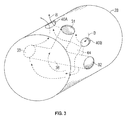
- FIG. 3 a perspective view of an embodiment of the member 28 disclosed herein is illustrated to help visualize its shape.
- the member 28 in this embodiment is cylindrical in shape, other embodiments could have alternate shapes, including spherical, for example.
Landscapes
- Engineering & Computer Science (AREA)
- General Engineering & Computer Science (AREA)
- Mechanical Engineering (AREA)
- Physics & Mathematics (AREA)
- Thermal Sciences (AREA)
- Health & Medical Sciences (AREA)
- General Health & Medical Sciences (AREA)
- Pulmonology (AREA)
- Aviation & Aerospace Engineering (AREA)
- Valve Housings (AREA)
Abstract
Description
- Valve arrangements, such as diverter valves, for example, typically rely upon rotation of a member within a housing to realigned openings in the member with passageways in the housing to alter porting of fluids therethrough. These devices serve the purpose for which they were designed. Using such devices in harsh environments that they may not have originally been designed for may affect smooth operation thereof. Alterations to such devices to allow smooth operation in ever more harsh conditions may be of interest to those who practice in the art.
- Disclosed herein is a heat exchanging valve arrangement that includes, a manifold defining a chamber, a first passageway, a second passageway, a third passageway, and a fourth passageway, and a member movable relative to the manifold configured to define fluidic communication between the first passageway and the second passageway when in a first position and between the first passageway and the third passageway when in a second position, fluid is flowable into the chamber through the fourth passageway such that fluid is exposed to surfaces of the member regardless of whether the member is in the first position or the second position.
- In addition to one or more of the features described above, or as an alternative, further embodiments include: wherein the member has a first opening, a second opening and a third opening all in fluidic communication with one another and the first opening is aligned with the first passageway, the second opening is aligned with the second passageway and the third opening is aligned with the fourth passageway when the member is in the first position thereby providing fluidic communication between the first passageway and the second passageway through the first opening and the second opening; wherein the first opening is aligned with the fourth passageway, the second opening is aligned with the first passageway and the third opening is aligned with the third passageway when the member is in the second position, thereby providing fluidic communication between the first passageway and the third passageway through the second opening and the third opening; wherein the member defines an inside that fluidically connects the first opening, the second opening and the third opening to one another; wherein walls that define the first opening, the second opening and the third opening also define inner radial features of a plenum, and fluid flowing from the chamber are free to flow through the plenum; wherein fluid flows into the plenum through a first port and out of the plenum through a second port when the member is in the first position and fluid flows into the plenum through the second port and out of the plenum through the first port when the member is in the second position; wherein seals between the member and the manifold occlude fluid flowing in the chamber from commingling with fluid within the member; wherein the seals sealingly engage with both the manifold and the outer radial surface of the member whether the member is in the first position or the second position; wherein the member is rotatably movable relative to the manifold; wherein the member rotates through about 90 degrees of rotation between the first position and the second position; wherein heat transfer between fluid in the manifold and the member prevent freezing the member in one of the first position and the second position; wherein the heat exchanging valve arrangement is a turbine outlet diverter valve; wherein subfreezing turbine air flows in through the first passageway and flows overboard out through the second passageway when the member is in the first position and subfreezing turbine air flows in through the first passageway and into a cabin of an aircraft through the third passageway when the member is in the second position; and wherein the manifold is configured to port subfreezing air into the fist passageway and warmed air into the fourth passageway.
- Further disclosed herein is a heat exchanging valve arrangement. The arrangement includes, a manifold defining multiple passageways, and a member movably disposed within the manifold having an inside fluidically connecting at least three openings and walls defining the at least three openings separating the inside from a plenum also defined within the member, the member is movable between a first position and a second position relative to the manifold, the heat exchanging valve arrangement is also configured such that fluid can enter the inside through a first of the multiple passageways and one of the at least three openings when the member is in the first position and exist the inside through another of the at least three openings and another of the multiple passageways when the member is in the second position, and fluid flowing into the plenum from yet another of the multiple passageways is exposed to the walls prior to mixing with fluid exiting the inside.
- The subject matter which is regarded as the present disclosure is particularly pointed out and distinctly claimed in the claims at the conclusion of the specification. The foregoing and other features, and advantages of the present disclosure are apparent from the following detailed description taken in conjunction with the accompanying drawings in which:
-
FIG. 1 depicts a side schematic view of a heat exchanging valve arrangement disclosed herein with a member shown in a first position; -
FIG. 2 depicts a side schematic view of the heat exchanging valve arrangement ofFIG. 1 with the member shown in a second position; and -
FIG. 3 depicts a perspective view of a member of the heat exchanging valve arrangement ofFIG. 1 . - Referring to
Figures 1-3 , an embodiment of a heat exchanging valve arrangement disclosed herein is schematically illustrated at 10. Thearrangement 10 includes, amanifold 14 defining at least one chamber 1 8, afirst passageway 21, asecond passageway 22, athird passageway 23, and afourth passageway 24. Also, amember 28 is movable relative to themanifold 14 and configured to define fluidic communication between thefirst passageway 21 and thesecond passageway 22 when in a first position (shown inFigure 1 ) and between thefirst passageway 21 and thethird passageway 23 when in a second position (shown inFigure 2 ). This fluidic communication may be for a first fluid flow stream designated by arrows 'A.' The first flow steam in one embodiment is a cold, possible sub-freezing, fluid. In this embodiment themember 28 it rotatable relative to themanifold 18. Rotation of themember 28 through 90 degrees in a counterclockwise direction moves themember 28 from the first position to the second position and vice versa. Regardless of whether themember 28 is in the first position or the second position fluid is able to flow into thechamber 18 through thefourth passageway 24 such that fluid in thechamber 18 is exposed tosurfaces 30 ofwalls 34 of themember 28. Fluid flowing through thefourth passageway 24 is a second flow stream designated by arrows 'B." In one embodiment the second flow steam is warm, such as near normal room temperature of about 70 degrees F and may be supplied from a cabin of an aircraft, for example. The first flow stream and the second flow stream mix when themember 28 is in the second position after the second flow stream flows through one ormore holes 52 that will be discussed in more detail below. - The
member 28 has at least afirst opening 31. a second opening 32 and a third opening 33 that are all in fluidic communication with one another via aninside 36 of themember 28. When themember 28 is in the first position thefirst opening 31 is aligned with thefirst passageway 21, thesecond opening 32 is aligned with thesecond passageway 22 and the third opening 33 is aligned with thefourth passageway 24 thereby providing fluidic communication between thefirst passageway 21 and thesecond passageway 22 through the first opening 31 and thesecond opening 32. - Similarly, when the
member 28 is in the second position thefirst opening 31 is aligned with thefourth passageway 24, thesecond opening 32 is aligned with thefirst passageway 21 and the third opening 33 is aligned with thethird passageway 23 thereby providing fluidic communication between thefirst passageway 21 and thethird passageway 23 through the second opening 32 and the third opening 33. - As mentioned above, fluid that flows in through the
fourth passageway 24 into thechamber 18 can be exposed to thesurfaces 30 of thewalls 34 of themember 28. Thewalls 34 separate theinside 36 from aplenum 44 on an outside of thewalls 34. Fluid from thefourth passageway 24 is able to flow into theplenum 44 through one of at least twoports member 28, note just two of theports member 28 is in the first position fluid flows into theplenum 44 through theport 40A, then through theplenum 44, is exposed to thesurfaces 30, and exits theplenum 44 through theother port 40B. When themember 28 is in the second position the flow through theports plenum 44 is through theport 40B and out through theport 40A. - The exposure of the
surfaces 30 to the fluid allows heat to be transferred between the fluid and themember 28. In situations wherein the fluid is above freezing, such heat transfer can prevent water from freezing between themember 28 and themanifold 14 that could lock themember 28 by requiring more force to move themember 28 between the first position and the second position. In an application wherein theheat exchanging valve 10 is a turbine outlet diverter valve flow through theinside 36 may be from an outlet of a turbine and be below freezing temperature, while flow into thefourth passageway 24 may be air from a cabin of an aircraft that is warmer than freezing. The paths for the warmed cabin air is able to circulate through theplenum 44 and warm thewalls 34 thereby preventing freezing of any water that may be present thereby avoiding locking movement of themember 28. - Seals 48 sealingly engage with both the
manifold 14 and themember 28 whether themember 28 is in the first position or the second position. Theseals 48 prevent fluid in thechamber 18 from commingling with fluid at theinside 36 of themember 28. One ormore holes 52 located downstream from the chamber 18 (and theplenum 44 when themember 28 is in the first position) allows the fluid flowing into thechamber 18 from thefourth passageway 24 to flow into adownstream portion 56 of thethird passageway 23 and in the process to comingle with fluid within thedownstream portion 56. - Referring to
Figure 3 , a perspective view of an embodiment of themember 28 disclosed herein is illustrated to help visualize its shape. Although themember 28 in this embodiment is cylindrical in shape, other embodiments could have alternate shapes, including spherical, for example. - While the present disclosure has been described in detail in connection with only a limited number of embodiments, it should be readily understood that the present disclosure is not limited to such disclosed embodiments. Rather, the present disclosure can be modified to incorporate any number of variations, alterations, substitutions or equivalent arrangements not heretofore described, but which are commensurate with the spirit and scope of the present disclosure. Additionally, while various embodiments of the present disclosure have been described, it is to be understood that aspects of the present disclosure may include only some of the described embodiments. Accordingly, the present disclosure is not to be seen as limited by the foregoing description, but is only limited by the scope of the appended claims.
Claims (15)
- A heat exchanging valve arrangement, comprising:a manifold (14) defining a chamber (18), a first passageway (21), a second passageway (22), a third passageway (23), and a fourth passageway (24); anda member (28) movable relative to the manifold (14) configured to define fluidic communication between the first passageway (21) and the second passageway (22) when in a first position and between the first passageway (21) and the third passageway (23) when in a second position, fluid being flowable into the chamber (18) through the fourth passageway (24) such that fluid is exposed to surfaces of the member (28) regardless of whether the member (28) is in the first position or the second position.
- The heat exchanging valve arrangement of claim 1, wherein the member (28) has a first opening (31), a second opening (32) and a third opening (33) all in fluidic communication with one another and the first opening (31) is aligned with the first passageway (21), the second opening (32) is aligned with the second passageway (22) and the third opening (33) is aligned with the fourth passageway (24) when the member (28) is in the first position thereby providing fluidic communication between the first passageway (21) and the second passageway (22) through the first opening (31) and the second opening (32).
- The heat exchanging valve arrangement of claim 2, wherein the first opening (31) is aligned with the fourth passageway (24), the second opening (32) is aligned with the first passageway (21) and the third opening (33) is aligned with the third passageway when the member is in the second position, thereby providing fluidic communication between the first passageway (21) and the third passageway (23) through the second opening (32) and the third opening (33).
- The heat exchanging valve arrangement of any preceding claim, wherein the member (28) defines an inside that fluidically connects the first opening (31), the second opening (32) and the third opening (33) to one another.
- The heat exchanging valve arrangement of claim 4, wherein walls that define the first opening (31), the second opening (32) and the third opening (33) also define inner radial features of a plenum (44), and fluid flowing from the chamber (18) are free to flow through the plenum (44).
- The heat exchanging valve arrangement of claim 5, wherein fluid flows into the plenum (44) through a first port (40A) and out of the plenum (44) through a second port (40B) when the member is in the first position and fluid flows into the plenum (44) through the second port (40B) and out of the plenum (44) through the first port (40A) when the member is in the second position.
- The heat exchanging valve arrangement of any preceding claim, wherein seals between the member (28) and the manifold occlude fluid flowing in the chamber (18) from commingling with fluid within the member.
- The heat exchanging valve arrangement of claim 4, wherein the seals sealingly engage with both the manifold and the outer radial surface of the member (28) whether the member is in the first position or the second position.
- The heat exchanging valve arrangement of any preceding claim, wherein the member (28) is rotatably movable relative to the manifold.
- The heat exchanging valve arrangement of any preceding claim, wherein the member (28) rotates through about 90 degrees of rotation between the first position and the second position.
- The heat exchanging valve arrangement, of any preceding claim wherein heat transfer between fluid in the manifold and the member (28) prevent freezing the member in one of the first position and the second position.
- The heat exchanging valve arrangement of any preceding claim, wherein the heat exchanging valve arrangement is a turbine outlet diverter valve.
- The heat exchanging valve arrangement of any preceding claim. wherein subfreezing turbine air flows in through the first passageway (21) and flows overboard out through the second passageway (22) when the member (28) is in the first position and subfreezing turbine air flows in through the first passageway (21) and into a cabin of an aircraft through the third passageway (23) when the member (28) is in the second position.
- The heat exchanging valve arrangement of any preceding claim, wherein the manifold is configured to port subfreezing air into the first passageway (21) and warmed air into the fourth passageway (24).
- A heat exchanging valve arrangement, comprising.
a manifold defining multiple passageways (21, 22, 23, 24); and
a member (28) movably disposed within the manifold having an inside fluidically connecting at least three openings (31, 32, 33) and walls defining the at least three openings separating the inside from a plenum (44) also defined within the member (28), the member (28) being movable between a first position and a second position relative to the manifold, the heat exchanging valve arrangement being configured such that fluid can enter the inside through a first of the multiple passageways (21, 22, 23, 24) and one of the at least three openings (31, 32, 33) when the member (28) is in the first position and exist the inside through another of the at least three openings (31, 32, 33) and another of the multiple passageways (21, 22, 23, 24) when the member is in the second position, and fluid flowing into the plenum (44) from yet another of the multiple passageways (21, 22, 23, 24) is exposed to the walls prior to mixing with fluid exiting the inside.
Applications Claiming Priority (1)
| Application Number | Priority Date | Filing Date | Title |
|---|---|---|---|
| US14/825,925 US9683678B2 (en) | 2015-08-13 | 2015-08-13 | Heat exchanging valve arrangement |
Publications (2)
| Publication Number | Publication Date |
|---|---|
| EP3135967A1 true EP3135967A1 (en) | 2017-03-01 |
| EP3135967B1 EP3135967B1 (en) | 2018-06-06 |
Family
ID=56883527
Family Applications (1)
| Application Number | Title | Priority Date | Filing Date |
|---|---|---|---|
| EP16183766.1A Active EP3135967B1 (en) | 2015-08-13 | 2016-08-11 | Heat exchanging valve arrangement |
Country Status (2)
| Country | Link |
|---|---|
| US (1) | US9683678B2 (en) |
| EP (1) | EP3135967B1 (en) |
Families Citing this family (4)
| Publication number | Priority date | Publication date | Assignee | Title |
|---|---|---|---|---|
| US9481477B2 (en) | 2012-09-17 | 2016-11-01 | Life Technologies Corporation | Fluid manifold system with rotatable port assembly |
| US10107417B2 (en) * | 2016-12-14 | 2018-10-23 | Fisher Controls International Llc | Single-piece valve closure members having integral flow paths formed via additive manufacturing |
| US11085546B2 (en) | 2018-04-10 | 2021-08-10 | Fisher Controls International Llc | Purge apparatus for use with fluid valves |
| US12492648B2 (en) * | 2024-05-17 | 2025-12-09 | Rtx Corporation | Modulated air-cooled heat exchanger for hybrid electric thermal management systems |
Citations (3)
| Publication number | Priority date | Publication date | Assignee | Title |
|---|---|---|---|---|
| US3411538A (en) * | 1966-04-16 | 1968-11-19 | Honeywell Gmbh | Fluid diverting valve |
| GB2279431A (en) * | 1993-06-22 | 1995-01-04 | Spirax Sarco Ltd | Condensate traps |
| DE19507919A1 (en) * | 1995-03-07 | 1996-09-12 | Buderus Heiztechnik Gmbh | Central changeover unit for fluid currents for periodically alternating series switching heat exchanger modules |
Family Cites Families (11)
| Publication number | Priority date | Publication date | Assignee | Title |
|---|---|---|---|---|
| USRE15965E (en) * | 1924-12-16 | A oobpobatiov | ||
| US916611A (en) * | 1907-01-16 | 1909-03-30 | David Frank | Sterilizing apparatus. |
| US1708273A (en) * | 1926-07-09 | 1929-04-09 | Creamery Package Mfg Co | Valve |
| ES415709A1 (en) * | 1973-06-08 | 1976-01-16 | Orbaiceta | Gas cock |
| US4430867A (en) * | 1981-08-24 | 1984-02-14 | United Technologies Corporation | Air cycle refrigeration system |
| US5461882A (en) | 1994-07-22 | 1995-10-31 | United Technologies Corporation | Regenerative condensing cycle |
| US5553461A (en) | 1995-01-11 | 1996-09-10 | Grumman Aerospace Corporation | Anti-icing heat exchanger for aircraft air cycle performance enhancement |
| EP1492704B1 (en) | 2002-04-08 | 2006-12-06 | Honeywell Normalair-Garrett (Holdings) Limited | Air conditioning system |
| CN100545493C (en) * | 2008-03-31 | 2009-09-30 | 艾欧史密斯(中国)热水器有限公司 | Thermostat mixing valve |
| US9003814B2 (en) * | 2011-11-11 | 2015-04-14 | Hamilton Sundstrand Corporation | Turbo air compressor with pressure recovery |
| US10184494B2 (en) | 2013-06-28 | 2019-01-22 | Hamilton Sundstrand Corporation | Enhance motor cooling system and method |
-
2015
- 2015-08-13 US US14/825,925 patent/US9683678B2/en active Active
-
2016
- 2016-08-11 EP EP16183766.1A patent/EP3135967B1/en active Active
Patent Citations (3)
| Publication number | Priority date | Publication date | Assignee | Title |
|---|---|---|---|---|
| US3411538A (en) * | 1966-04-16 | 1968-11-19 | Honeywell Gmbh | Fluid diverting valve |
| GB2279431A (en) * | 1993-06-22 | 1995-01-04 | Spirax Sarco Ltd | Condensate traps |
| DE19507919A1 (en) * | 1995-03-07 | 1996-09-12 | Buderus Heiztechnik Gmbh | Central changeover unit for fluid currents for periodically alternating series switching heat exchanger modules |
Also Published As
| Publication number | Publication date |
|---|---|
| US9683678B2 (en) | 2017-06-20 |
| US20170045155A1 (en) | 2017-02-16 |
| EP3135967B1 (en) | 2018-06-06 |
Similar Documents
| Publication | Publication Date | Title |
|---|---|---|
| EP3135967B1 (en) | Heat exchanging valve arrangement | |
| EP3280937B1 (en) | Multiway valve with bypass circuit | |
| JP6510810B2 (en) | Flow path switching valve | |
| JP2019213919A5 (en) | ||
| US9416884B2 (en) | Fluid control valve and assembly | |
| CN107580653B (en) | Combined butterfly/ball valve | |
| US9683677B2 (en) | Bypass valve and hydraulic unit including such a valve | |
| US20230175599A1 (en) | Multi-port coolant flow control valve assembly | |
| US8789560B2 (en) | Fluid valve fitting having an integrated fluid bypass valve | |
| EP2940357A1 (en) | Fluid control valve | |
| WO2011032156A3 (en) | Cooler bypass apparatus and installation kit | |
| CN113348326B (en) | Distribution pump device for a hydraulic distribution system with variable flow direction | |
| US20160369908A1 (en) | Ball Valve Assembly | |
| EP3680524B1 (en) | Actuating mechanism | |
| CN105318039A (en) | Three-way valve | |
| US20130228247A1 (en) | Canted, single vane, three-way butterfly valve | |
| CN104033622B (en) | A kind of three-way valve | |
| CN111434959B (en) | Driving mechanism | |
| JP6428530B2 (en) | Switching valve and water heater | |
| US9719601B2 (en) | Canted, single vane, three-way butterfly valve | |
| CN104100765A (en) | Ball shaft for a liquid coolant valve | |
| CN111434960B (en) | Control valve | |
| EP2696121B1 (en) | Shutoff valve with anti freeze system | |
| KR101029067B1 (en) | Multi-directional valve | |
| CN105782508B (en) | bypass valve |
Legal Events
| Date | Code | Title | Description |
|---|---|---|---|
| PUAI | Public reference made under article 153(3) epc to a published international application that has entered the european phase |
Free format text: ORIGINAL CODE: 0009012 |
|
| STAA | Information on the status of an ep patent application or granted ep patent |
Free format text: STATUS: THE APPLICATION HAS BEEN PUBLISHED |
|
| AK | Designated contracting states |
Kind code of ref document: A1 Designated state(s): AL AT BE BG CH CY CZ DE DK EE ES FI FR GB GR HR HU IE IS IT LI LT LU LV MC MK MT NL NO PL PT RO RS SE SI SK SM TR |
|
| AX | Request for extension of the european patent |
Extension state: BA ME |
|
| STAA | Information on the status of an ep patent application or granted ep patent |
Free format text: STATUS: REQUEST FOR EXAMINATION WAS MADE |
|
| 17P | Request for examination filed |
Effective date: 20170830 |
|
| RBV | Designated contracting states (corrected) |
Designated state(s): AL AT BE BG CH CY CZ DE DK EE ES FI FR GB GR HR HU IE IS IT LI LT LU LV MC MK MT NL NO PL PT RO RS SE SI SK SM TR |
|
| GRAP | Despatch of communication of intention to grant a patent |
Free format text: ORIGINAL CODE: EPIDOSNIGR1 |
|
| STAA | Information on the status of an ep patent application or granted ep patent |
Free format text: STATUS: GRANT OF PATENT IS INTENDED |
|
| INTG | Intention to grant announced |
Effective date: 20171215 |
|
| GRAS | Grant fee paid |
Free format text: ORIGINAL CODE: EPIDOSNIGR3 |
|
| GRAA | (expected) grant |
Free format text: ORIGINAL CODE: 0009210 |
|
| STAA | Information on the status of an ep patent application or granted ep patent |
Free format text: STATUS: THE PATENT HAS BEEN GRANTED |
|
| AK | Designated contracting states |
Kind code of ref document: B1 Designated state(s): AL AT BE BG CH CY CZ DE DK EE ES FI FR GB GR HR HU IE IS IT LI LT LU LV MC MK MT NL NO PL PT RO RS SE SI SK SM TR |
|
| REG | Reference to a national code |
Ref country code: GB Ref legal event code: FG4D |
|
| REG | Reference to a national code |
Ref country code: CH Ref legal event code: EP Ref country code: AT Ref legal event code: REF Ref document number: 1006452 Country of ref document: AT Kind code of ref document: T Effective date: 20180615 |
|
| REG | Reference to a national code |
Ref country code: IE Ref legal event code: FG4D |
|
| REG | Reference to a national code |
Ref country code: DE Ref legal event code: R096 Ref document number: 602016003319 Country of ref document: DE |
|
| REG | Reference to a national code |
Ref country code: FR Ref legal event code: PLFP Year of fee payment: 3 |
|
| REG | Reference to a national code |
Ref country code: NL Ref legal event code: MP Effective date: 20180606 |
|
| REG | Reference to a national code |
Ref country code: LT Ref legal event code: MG4D |
|
| PG25 | Lapsed in a contracting state [announced via postgrant information from national office to epo] |
Ref country code: NO Free format text: LAPSE BECAUSE OF FAILURE TO SUBMIT A TRANSLATION OF THE DESCRIPTION OR TO PAY THE FEE WITHIN THE PRESCRIBED TIME-LIMIT Effective date: 20180906 Ref country code: BG Free format text: LAPSE BECAUSE OF FAILURE TO SUBMIT A TRANSLATION OF THE DESCRIPTION OR TO PAY THE FEE WITHIN THE PRESCRIBED TIME-LIMIT Effective date: 20180906 Ref country code: FI Free format text: LAPSE BECAUSE OF FAILURE TO SUBMIT A TRANSLATION OF THE DESCRIPTION OR TO PAY THE FEE WITHIN THE PRESCRIBED TIME-LIMIT Effective date: 20180606 Ref country code: ES Free format text: LAPSE BECAUSE OF FAILURE TO SUBMIT A TRANSLATION OF THE DESCRIPTION OR TO PAY THE FEE WITHIN THE PRESCRIBED TIME-LIMIT Effective date: 20180606 Ref country code: SE Free format text: LAPSE BECAUSE OF FAILURE TO SUBMIT A TRANSLATION OF THE DESCRIPTION OR TO PAY THE FEE WITHIN THE PRESCRIBED TIME-LIMIT Effective date: 20180606 Ref country code: LT Free format text: LAPSE BECAUSE OF FAILURE TO SUBMIT A TRANSLATION OF THE DESCRIPTION OR TO PAY THE FEE WITHIN THE PRESCRIBED TIME-LIMIT Effective date: 20180606 Ref country code: CY Free format text: LAPSE BECAUSE OF FAILURE TO SUBMIT A TRANSLATION OF THE DESCRIPTION OR TO PAY THE FEE WITHIN THE PRESCRIBED TIME-LIMIT Effective date: 20180606 |
|
| PG25 | Lapsed in a contracting state [announced via postgrant information from national office to epo] |
Ref country code: LV Free format text: LAPSE BECAUSE OF FAILURE TO SUBMIT A TRANSLATION OF THE DESCRIPTION OR TO PAY THE FEE WITHIN THE PRESCRIBED TIME-LIMIT Effective date: 20180606 Ref country code: HR Free format text: LAPSE BECAUSE OF FAILURE TO SUBMIT A TRANSLATION OF THE DESCRIPTION OR TO PAY THE FEE WITHIN THE PRESCRIBED TIME-LIMIT Effective date: 20180606 Ref country code: GR Free format text: LAPSE BECAUSE OF FAILURE TO SUBMIT A TRANSLATION OF THE DESCRIPTION OR TO PAY THE FEE WITHIN THE PRESCRIBED TIME-LIMIT Effective date: 20180907 Ref country code: RS Free format text: LAPSE BECAUSE OF FAILURE TO SUBMIT A TRANSLATION OF THE DESCRIPTION OR TO PAY THE FEE WITHIN THE PRESCRIBED TIME-LIMIT Effective date: 20180606 |
|
| REG | Reference to a national code |
Ref country code: AT Ref legal event code: MK05 Ref document number: 1006452 Country of ref document: AT Kind code of ref document: T Effective date: 20180606 |
|
| PG25 | Lapsed in a contracting state [announced via postgrant information from national office to epo] |
Ref country code: NL Free format text: LAPSE BECAUSE OF FAILURE TO SUBMIT A TRANSLATION OF THE DESCRIPTION OR TO PAY THE FEE WITHIN THE PRESCRIBED TIME-LIMIT Effective date: 20180606 |
|
| PG25 | Lapsed in a contracting state [announced via postgrant information from national office to epo] |
Ref country code: EE Free format text: LAPSE BECAUSE OF FAILURE TO SUBMIT A TRANSLATION OF THE DESCRIPTION OR TO PAY THE FEE WITHIN THE PRESCRIBED TIME-LIMIT Effective date: 20180606 Ref country code: PL Free format text: LAPSE BECAUSE OF FAILURE TO SUBMIT A TRANSLATION OF THE DESCRIPTION OR TO PAY THE FEE WITHIN THE PRESCRIBED TIME-LIMIT Effective date: 20180606 Ref country code: IS Free format text: LAPSE BECAUSE OF FAILURE TO SUBMIT A TRANSLATION OF THE DESCRIPTION OR TO PAY THE FEE WITHIN THE PRESCRIBED TIME-LIMIT Effective date: 20181006 Ref country code: RO Free format text: LAPSE BECAUSE OF FAILURE TO SUBMIT A TRANSLATION OF THE DESCRIPTION OR TO PAY THE FEE WITHIN THE PRESCRIBED TIME-LIMIT Effective date: 20180606 Ref country code: AT Free format text: LAPSE BECAUSE OF FAILURE TO SUBMIT A TRANSLATION OF THE DESCRIPTION OR TO PAY THE FEE WITHIN THE PRESCRIBED TIME-LIMIT Effective date: 20180606 Ref country code: CZ Free format text: LAPSE BECAUSE OF FAILURE TO SUBMIT A TRANSLATION OF THE DESCRIPTION OR TO PAY THE FEE WITHIN THE PRESCRIBED TIME-LIMIT Effective date: 20180606 Ref country code: SK Free format text: LAPSE BECAUSE OF FAILURE TO SUBMIT A TRANSLATION OF THE DESCRIPTION OR TO PAY THE FEE WITHIN THE PRESCRIBED TIME-LIMIT Effective date: 20180606 |
|
| PG25 | Lapsed in a contracting state [announced via postgrant information from national office to epo] |
Ref country code: SM Free format text: LAPSE BECAUSE OF FAILURE TO SUBMIT A TRANSLATION OF THE DESCRIPTION OR TO PAY THE FEE WITHIN THE PRESCRIBED TIME-LIMIT Effective date: 20180606 Ref country code: IT Free format text: LAPSE BECAUSE OF FAILURE TO SUBMIT A TRANSLATION OF THE DESCRIPTION OR TO PAY THE FEE WITHIN THE PRESCRIBED TIME-LIMIT Effective date: 20180606 |
|
| REG | Reference to a national code |
Ref country code: DE Ref legal event code: R119 Ref document number: 602016003319 Country of ref document: DE |
|
| PG25 | Lapsed in a contracting state [announced via postgrant information from national office to epo] |
Ref country code: MC Free format text: LAPSE BECAUSE OF FAILURE TO SUBMIT A TRANSLATION OF THE DESCRIPTION OR TO PAY THE FEE WITHIN THE PRESCRIBED TIME-LIMIT Effective date: 20180606 |
|
| PLBE | No opposition filed within time limit |
Free format text: ORIGINAL CODE: 0009261 |
|
| STAA | Information on the status of an ep patent application or granted ep patent |
Free format text: STATUS: NO OPPOSITION FILED WITHIN TIME LIMIT |
|
| PG25 | Lapsed in a contracting state [announced via postgrant information from national office to epo] |
Ref country code: LU Free format text: LAPSE BECAUSE OF NON-PAYMENT OF DUE FEES Effective date: 20180811 |
|
| REG | Reference to a national code |
Ref country code: BE Ref legal event code: MM Effective date: 20180831 |
|
| 26N | No opposition filed |
Effective date: 20190307 |
|
| REG | Reference to a national code |
Ref country code: IE Ref legal event code: MM4A |
|
| PG25 | Lapsed in a contracting state [announced via postgrant information from national office to epo] |
Ref country code: SI Free format text: LAPSE BECAUSE OF FAILURE TO SUBMIT A TRANSLATION OF THE DESCRIPTION OR TO PAY THE FEE WITHIN THE PRESCRIBED TIME-LIMIT Effective date: 20180606 Ref country code: DK Free format text: LAPSE BECAUSE OF FAILURE TO SUBMIT A TRANSLATION OF THE DESCRIPTION OR TO PAY THE FEE WITHIN THE PRESCRIBED TIME-LIMIT Effective date: 20180606 |
|
| PG25 | Lapsed in a contracting state [announced via postgrant information from national office to epo] |
Ref country code: DE Free format text: LAPSE BECAUSE OF NON-PAYMENT OF DUE FEES Effective date: 20190301 Ref country code: IE Free format text: LAPSE BECAUSE OF NON-PAYMENT OF DUE FEES Effective date: 20180811 |
|
| PG25 | Lapsed in a contracting state [announced via postgrant information from national office to epo] |
Ref country code: BE Free format text: LAPSE BECAUSE OF NON-PAYMENT OF DUE FEES Effective date: 20180831 |
|
| PG25 | Lapsed in a contracting state [announced via postgrant information from national office to epo] |
Ref country code: AL Free format text: LAPSE BECAUSE OF FAILURE TO SUBMIT A TRANSLATION OF THE DESCRIPTION OR TO PAY THE FEE WITHIN THE PRESCRIBED TIME-LIMIT Effective date: 20180606 |
|
| PG25 | Lapsed in a contracting state [announced via postgrant information from national office to epo] |
Ref country code: MT Free format text: LAPSE BECAUSE OF NON-PAYMENT OF DUE FEES Effective date: 20180811 |
|
| PG25 | Lapsed in a contracting state [announced via postgrant information from national office to epo] |
Ref country code: TR Free format text: LAPSE BECAUSE OF FAILURE TO SUBMIT A TRANSLATION OF THE DESCRIPTION OR TO PAY THE FEE WITHIN THE PRESCRIBED TIME-LIMIT Effective date: 20180606 |
|
| PG25 | Lapsed in a contracting state [announced via postgrant information from national office to epo] |
Ref country code: PT Free format text: LAPSE BECAUSE OF FAILURE TO SUBMIT A TRANSLATION OF THE DESCRIPTION OR TO PAY THE FEE WITHIN THE PRESCRIBED TIME-LIMIT Effective date: 20180606 Ref country code: LI Free format text: LAPSE BECAUSE OF NON-PAYMENT OF DUE FEES Effective date: 20190831 Ref country code: CH Free format text: LAPSE BECAUSE OF NON-PAYMENT OF DUE FEES Effective date: 20190831 |
|
| PG25 | Lapsed in a contracting state [announced via postgrant information from national office to epo] |
Ref country code: HU Free format text: LAPSE BECAUSE OF FAILURE TO SUBMIT A TRANSLATION OF THE DESCRIPTION OR TO PAY THE FEE WITHIN THE PRESCRIBED TIME-LIMIT; INVALID AB INITIO Effective date: 20160811 Ref country code: MK Free format text: LAPSE BECAUSE OF NON-PAYMENT OF DUE FEES Effective date: 20180606 |
|
| P01 | Opt-out of the competence of the unified patent court (upc) registered |
Effective date: 20230522 |
|
| PGFP | Annual fee paid to national office [announced via postgrant information from national office to epo] |
Ref country code: GB Payment date: 20250724 Year of fee payment: 10 |
|
| PGFP | Annual fee paid to national office [announced via postgrant information from national office to epo] |
Ref country code: FR Payment date: 20250723 Year of fee payment: 10 |