EP3135950A1 - Self-tuning tunable mass dampers and method for operation - Google Patents
Self-tuning tunable mass dampers and method for operation Download PDFInfo
- Publication number
- EP3135950A1 EP3135950A1 EP16172855.5A EP16172855A EP3135950A1 EP 3135950 A1 EP3135950 A1 EP 3135950A1 EP 16172855 A EP16172855 A EP 16172855A EP 3135950 A1 EP3135950 A1 EP 3135950A1
- Authority
- EP
- European Patent Office
- Prior art keywords
- magnet
- voice coil
- tmd
- frequency
- mass damper
- Prior art date
- Legal status (The legal status is an assumption and is not a legal conclusion. Google has not performed a legal analysis and makes no representation as to the accuracy of the status listed.)
- Granted
Links
Images



Classifications
-
- F—MECHANICAL ENGINEERING; LIGHTING; HEATING; WEAPONS; BLASTING
- F16—ENGINEERING ELEMENTS AND UNITS; GENERAL MEASURES FOR PRODUCING AND MAINTAINING EFFECTIVE FUNCTIONING OF MACHINES OR INSTALLATIONS; THERMAL INSULATION IN GENERAL
- F16F—SPRINGS; SHOCK-ABSORBERS; MEANS FOR DAMPING VIBRATION
- F16F15/00—Suppression of vibrations in systems; Means or arrangements for avoiding or reducing out-of-balance forces, e.g. due to motion
- F16F15/30—Flywheels
- F16F15/315—Flywheels characterised by their supporting arrangement, e.g. mountings, cages, securing inertia member to shaft
-
- F—MECHANICAL ENGINEERING; LIGHTING; HEATING; WEAPONS; BLASTING
- F16—ENGINEERING ELEMENTS AND UNITS; GENERAL MEASURES FOR PRODUCING AND MAINTAINING EFFECTIVE FUNCTIONING OF MACHINES OR INSTALLATIONS; THERMAL INSULATION IN GENERAL
- F16F—SPRINGS; SHOCK-ABSORBERS; MEANS FOR DAMPING VIBRATION
- F16F7/00—Vibration-dampers; Shock-absorbers
- F16F7/10—Vibration-dampers; Shock-absorbers using inertia effect
- F16F7/1005—Vibration-dampers; Shock-absorbers using inertia effect characterised by active control of the mass
- F16F7/1011—Vibration-dampers; Shock-absorbers using inertia effect characterised by active control of the mass by electromagnetic means
-
- E—FIXED CONSTRUCTIONS
- E04—BUILDING
- E04H—BUILDINGS OR LIKE STRUCTURES FOR PARTICULAR PURPOSES; SWIMMING OR SPLASH BATHS OR POOLS; MASTS; FENCING; TENTS OR CANOPIES, IN GENERAL
- E04H9/00—Buildings, groups of buildings or shelters adapted to withstand or provide protection against abnormal external influences, e.g. war-like action, earthquake or extreme climate
- E04H9/02—Buildings, groups of buildings or shelters adapted to withstand or provide protection against abnormal external influences, e.g. war-like action, earthquake or extreme climate withstanding earthquake or sinking of ground
- E04H9/021—Bearing, supporting or connecting constructions specially adapted for such buildings
- E04H9/0215—Bearing, supporting or connecting constructions specially adapted for such buildings involving active or passive dynamic mass damping systems
-
- E—FIXED CONSTRUCTIONS
- E04—BUILDING
- E04H—BUILDINGS OR LIKE STRUCTURES FOR PARTICULAR PURPOSES; SWIMMING OR SPLASH BATHS OR POOLS; MASTS; FENCING; TENTS OR CANOPIES, IN GENERAL
- E04H9/00—Buildings, groups of buildings or shelters adapted to withstand or provide protection against abnormal external influences, e.g. war-like action, earthquake or extreme climate
- E04H9/02—Buildings, groups of buildings or shelters adapted to withstand or provide protection against abnormal external influences, e.g. war-like action, earthquake or extreme climate withstanding earthquake or sinking of ground
- E04H9/027—Preventive constructional measures against earthquake damage in existing buildings
-
- F—MECHANICAL ENGINEERING; LIGHTING; HEATING; WEAPONS; BLASTING
- F16—ENGINEERING ELEMENTS AND UNITS; GENERAL MEASURES FOR PRODUCING AND MAINTAINING EFFECTIVE FUNCTIONING OF MACHINES OR INSTALLATIONS; THERMAL INSULATION IN GENERAL
- F16F—SPRINGS; SHOCK-ABSORBERS; MEANS FOR DAMPING VIBRATION
- F16F7/00—Vibration-dampers; Shock-absorbers
- F16F7/10—Vibration-dampers; Shock-absorbers using inertia effect
- F16F7/104—Vibration-dampers; Shock-absorbers using inertia effect the inertia member being resiliently mounted
-
- F—MECHANICAL ENGINEERING; LIGHTING; HEATING; WEAPONS; BLASTING
- F16—ENGINEERING ELEMENTS AND UNITS; GENERAL MEASURES FOR PRODUCING AND MAINTAINING EFFECTIVE FUNCTIONING OF MACHINES OR INSTALLATIONS; THERMAL INSULATION IN GENERAL
- F16F—SPRINGS; SHOCK-ABSORBERS; MEANS FOR DAMPING VIBRATION
- F16F7/00—Vibration-dampers; Shock-absorbers
- F16F7/10—Vibration-dampers; Shock-absorbers using inertia effect
- F16F7/104—Vibration-dampers; Shock-absorbers using inertia effect the inertia member being resiliently mounted
- F16F7/116—Vibration-dampers; Shock-absorbers using inertia effect the inertia member being resiliently mounted on metal springs
Definitions
- Embodiments of the disclosure relate generally to the field of damping of dynamic resonance in aerospace structures and more particularly to a tuned mass damper (TMD) employing a voice coil / magnet combination as both an actuator and a lossy element for measuring and adjusting the TMD and structural response in an aerospace structure to which the TMD is attached and then adjusting the lossy element to self-tune the TMD for maximum reduction in dynamic response of the aerospace structure and TMD combination.
- TMD tuned mass damper
- Tuned mass dampers are heavily damped resonant devices which add damping to lightly damped vibrational modes of a structure by dynamically coupling into the lightly damped modes.
- a TMD is a damped spring/mass resonator that is tuned so that its frequency is close to a lightly damped mode on the host structure.
- the TMD is attached to the host structure at a location of large amplitude motion for the mode in question and its motion is coupled into the host structure's motion. If the TMD is tuned correctly, two damped vibrational modes result, which take the place of the original lightly damped mode of the host structure and heavily damped mode of the TMD. Since aerospace structures tend to respond unfavorably at lightly damped modes in the presence of a dynamic disturbance environment, introduction of one or several TMDs can greatly reduce the dynamic response of a structure by damping problematic modes.
- Tuning involves the determination of the correct values of uncoupled natural frequency and damping for the device that yields the best performance in the coupled device.
- Finite element models are helpful in predicting the host structure dynamics, which can then be used to determine the frequency, damping and mass of the TMD that gives the best performance, but the finite element model has to be very accurate to be useful.
- Measured mode shapes of the structure without TMDs can also be used to determine the frequency, damping and mass of the TMD that gives the best performance.
- a typical installation involves using a finite element model to determine the moving mass in the TMD and the range of damping and frequencies required. Experimental data is then used to "tune" the frequency, damping and mass to the values that cause the biggest response reduction in host structure response. This process is often tedious and requires several iterations.
- Embodiments disclosed herein provide a tunable mass damper having a frame and a voice coil supported in the frame.
- a magnet concentric with the voice coil is movable relative to the housing via the voice coil.
- a plurality of flexures having a first end extending from the magnet and an arm releasably coupled to the frame, said flexures adjustable for a desired frequency of reciprocation of the magnet.
- a method for operation of a tunable mass damper includes attaching a TMD having a voice coil and concentric magnet as a moving mass to a host structure at a location with an anticipated large dynamic response. Flexure clamps are released and flexure length is adjusted on the TMD by using the voice coil to urge the magnet and associated ramps into contact with bearing guides to rotate the magnet and flexures to obtain a desired frequency of the TMD. The flexures are then reclamped for operation of the TMD.
- Embodiments disclosed herein provide a TMD having a resilient element such as a spring, a moving mass and a lossy element to introduce damping.
- the spring is designed to guide the motion of the TMD for reciprocation on a desired axis through the TMD. If a shorted voice coil combined with a magnet is used as the lossy element, an added benefit can be realized by changing the resistance across the coil to change the damping.
- TMDs with voice coil loss mechanisms are commercially available from CSA/Moog (http://www.csaengineering.com/products-services/tuned-mass-dampers-absorbers/tmd-products/).
- the self-tuning TMD disclosed in the present embodiment uses the voice coil / magnet combination as both an actuator and a lossy element which enables an innovative stiffness adjustment mechanism.
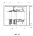
- FIGs. 1A-1C The basic components of the self-tuning TMD are shown in FIGs. 1A-1C .
- a voice coil 10 with a core 12 is supported in a frame 14.
- the frame employs a top flange 15a and a bottom flange 15b spaced apart and connected by columns 15c.
- a closed housing may be employed in alternative embodiments.
- the magnet 16 provides the moving mass for the TMD that reciprocates concentrically on an axis 20.
- the flexures 18a and 18b are supported by pillars 20 extending from the frame 14.
- the plurality of flexures have a first end extending from the magnet 16 and an arm 19 releasably coupled to the frame 14.
- the flexures 18a and 18b each have three symmetrical arms 19.
- the flexures may be supported by various attachments on the columns 15c replacing the pillars 20 and alternative numbers of arms and associated pillars may be employed for the flexures to support magnet 16.
- the voice coil 10 can be actively powered and used to move the magnet 16 up or down from the neutral position shown in FIG. 1B .
- a large voltage applied to the voice coil by a control system pushes magnet 16 axially to engage bearing race ramps 22a or 22b, which are attached to the magnet 16, against bearing guides 24a or 24b, which are attached to the frame 14.
- Axial engagement of the ramps and guides causes rotation of the magnet 16.
- Rotation of the magnet 16 causes rotation of the attached flexures 18a and 18b. If the magnet 16 is pushed downwardly in the depiction in the drawings as shown in FIG. 2A , contact between the bearing race ramps 22b and the bearing guides 24b force the magnet to turn in a counter clockwise direction.
- the flexures 18a and 18b which resiliently support the magnet 16 with respect to the frame 14, incorporate arcuate slots 26 which are substantially concentric around axis 20 and engage pins 28 extending from the pillars 20.
- the pins 28 are received within the slots 26, and each pin is positionable in the slot 26 for adjustment of an effective length of said flexure 18.
- Normally closed solenoids 30 lock down clamps 31 to secure the flexures when no voltage is applied and release the clamps when a voltage is applied.
- the flexures 18a and 18b are locked at a selected position along the slots 26 which centers the magnet and allows it to vibrate relative to the voice coil 10.
- the natural or resonant frequency of the vibration of the magnet mass in the TMD can be changed through changing the effective length of the flexures 18a and 18b by positioning the pins 28 and clamps 31 with respect to the slots 26.
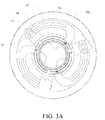
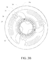
- a clockwise motion of the magnet 16 lengthens the flexure along a range of the slots 26 terminating at a distal end 32 as shown in FIG. 3A , where a counter clockwise motion of the magnet 16 shortens the flexure along the range of the slots terminating at a proximal end 34 as shown in FIG. 3B .
- Clockwise rotation may be enabled via first ramps 22a attached to the magnet 16, which when moved in a first direction engage first guide elements 24a to cause the magnet 16 and flexural members 18a, 18b to rotate in a clockwise direction.
- Counterclockwise rotation may be enabled via second ramps22b attached to the magnet 16, which when moved in a second direction engage second guide elements 24b to cause the magnet 16 and flexural members 18a, 18b to rotate in a counter-clockwise direction.
- a clamp 31 is actuated by a solenoid 30 to clamp on at least one flexural member, and is configured to allow the magnet16 and flexural members 18a, 18b to rotate when the solenoid is in a first state, and to clamp the flexural members in a fixed position when the solenoid is in a second state.
- the solenoid 30 may be powered for activation in the first state, and deactivated in the second state whereby the clamp is engaged in a failure condition of the solenoid. Accordingly, rotation in the first direction lengthens the effective length of the flexural members and rotation in the second direction shortens the effective length of the flexural members, such that the tuned mass damper frequency is adjustable by changing the effective length of the flexure members.
- the frequency is adjustable over a range based on the location of the clamps 31 and pins 28 in the slots 26.
- a voltage is also applied by the control system to the solenoids 30 releasing the clamps 31 to allow sliding of the flexures relative to the pins 28 supported by the pillars 20.
- the damping of the TMD can be changed by varying resistance across the voice coil 10 using, for example, a digitally programmable analog resistor. Increasing the resistance makes the inductive interaction between the voice coil 10 and magnet 16 more lossy while decreasing the resistance makes the interaction less lossy.
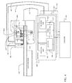
- a control system as shown in FIG. 4 may be employed to actively control the voice coil 10 for clocking the magnet 16 to alter the resonant frequency of the TMD or to cause excitation of the magnet allowing the TMD to act like a shaker or a modal hammer.
- a control computer 402 employs control algorithms to act on inputs received through an control interface 403 which may include an analog to digital (A/D) and digital to analog (D/A) interface 404 and provides control output through a voice coil amplifier 406 to actively position or drive the voice coil 10 as previously described.
- the control system may include encoded instructions therein for calculating an optimum frequency range based on input from the at least one accelerometer.
- the control system is configured to activate the at least one solenoid actuated clamp 31 and control the voice coil 12 to rotate the magnet to adjust the flexural members 18a, 18b to an effective length corresponding to the calculated frequency.
- a solenoid amplifier 408 is connected to the control computer 402 to controllably release the solenoids 30 an associated clamps 31 as previously described.
- a removable tether 412 couples the control system components to the TMD 400 with connections to the solenoids 30 and voice coil 10 and additional connection to at least one accelerometer 414 on the host structure 416, at least one accelerometer 418a associated with the magnet 16 and at least one accelerometer 418b mounted to the frame 14. Data from the accelerometers is processed through the signal conditioning elements 410 and A/D in the A/D & D/A interface 404.
- the self-tuning TMD can be adjusted to a selected test frequency well below the lowest frequency in the band and measure a collocated transfer function between current into the voice coil and acceleration of the base.
- a current mode amplifier as one of the signal conditioning elements 410 would be required.
- a transfer function between voltage into the voice coil and the acceleration of the base could be used, however, this transfer function will be affected by addition of some damping through back EMF.
- the transfer function selected will give insight into the uncoupled behavior of the host structure and may be used as the starting point for an algorithm to tune the TMD.
- the measured transfer function will show lightly damped modes that are good candidates for damping to reduce the host structure response.
- the control system is configured to analyze a frequency band that includes more than one lightly damped resonance frequency and determine an optimum frequency and damping to minimize the effect of vibration.
- This technique may also be applied with multiple TMDs (shown as elements 400 with associated interfaces 403 in FIG. 4 ) mounted to the structure with at least one TMD connected for driving the voice coil as an actuator. With all of the TMDs tuned to the selected test frequency, the accelerometers in all TMDs could then be sampled to collect response data and the determination by the control system may be made for optimization of all of the TMDs to reduce response to a disturbance at or near the TMD which was driven as the actuator. Each TMD may then be adjusted using the voice coil to clock the magnets in each TMD as described above and the control computer may adjust the programmable resistance for each TMD to provide the desired response.
- a self-tuning TMD having the structure of the described embodiment is attached to a host structure at a location with an anticipated large dynamic response, step 502.
- a tether is then attached to at least one TMD to provide power to the voice coil and solenoids and to receive signals from accelerometers mounted on the TMD frame, magnet and host structure, step 504.
- a control system is employed to release the flexure clamps and the TMD is adjusted by using the voice coil to urge the magnet and ramps into contact with the bearing guides to adjust the frequency of the TMD below the frequency band of interest and reclamp the flexures, step 506.
- the control system then actuates the voice coil as a shaker and measures the resulting uncoupled host transfer function, step 508.
- the uncoupled host transfer function and a predetermined tuning logic are employed to determine a preferred TMD frequency and damping, step 510.
- the control system is then employed to again release the flexure clamps and the TMD is adjusted by using the voice coil to urge the magnet and ramps into contact with the bearing guides to adjust flexure length to obtain the desired frequency of the TMD and reclamp the flexures, step 512.
- the control system alters voltage on a digitally programmable analog resistor across the voice coil to set the desired damping, step 514.
- the control system may then again activate the voice coil as a shaker and measure the resulting coupled host transfer function with the accelerometers to compare to the predicted transfer function, step 516.
- Steps 506 through 516 may then be repeated until a convergence criteria is satisfied, step 518.
- the tether is then removed from the TMD, step 520 and the TMD is ready for autonomous operation for dynamically damping the host structure. While the steps herein are described with respect to at least one TMD, a plurality of TMDs may be connected, activated, measured and tuned as a group to be optimized for desired damping of the structure to which the TMDs are attached as previously described.
- a single TMD of the plurality may be activated as the shaker while all TMDs in the plurality may be measured and tuned.
Landscapes
- Engineering & Computer Science (AREA)
- General Engineering & Computer Science (AREA)
- Architecture (AREA)
- Mechanical Engineering (AREA)
- Business, Economics & Management (AREA)
- Emergency Management (AREA)
- Environmental & Geological Engineering (AREA)
- Physics & Mathematics (AREA)
- Electromagnetism (AREA)
- Structural Engineering (AREA)
- Civil Engineering (AREA)
- Aviation & Aerospace Engineering (AREA)
- Acoustics & Sound (AREA)
- Reciprocating, Oscillating Or Vibrating Motors (AREA)
- Audible-Bandwidth Dynamoelectric Transducers Other Than Pickups (AREA)
- Vibration Prevention Devices (AREA)
- Springs (AREA)
- Apparatuses For Generation Of Mechanical Vibrations (AREA)
Abstract
Description
- Embodiments of the disclosure relate generally to the field of damping of dynamic resonance in aerospace structures and more particularly to a tuned mass damper (TMD) employing a voice coil / magnet combination as both an actuator and a lossy element for measuring and adjusting the TMD and structural response in an aerospace structure to which the TMD is attached and then adjusting the lossy element to self-tune the TMD for maximum reduction in dynamic response of the aerospace structure and TMD combination.
- Tuned mass dampers (TMDs) are heavily damped resonant devices which add damping to lightly damped vibrational modes of a structure by dynamically coupling into the lightly damped modes. In practice, a TMD is a damped spring/mass resonator that is tuned so that its frequency is close to a lightly damped mode on the host structure. The TMD is attached to the host structure at a location of large amplitude motion for the mode in question and its motion is coupled into the host structure's motion. If the TMD is tuned correctly, two damped vibrational modes result, which take the place of the original lightly damped mode of the host structure and heavily damped mode of the TMD. Since aerospace structures tend to respond unfavorably at lightly damped modes in the presence of a dynamic disturbance environment, introduction of one or several TMDs can greatly reduce the dynamic response of a structure by damping problematic modes.
- One of the challenges associated with installation of TMDs is tuning. Tuning involves the determination of the correct values of uncoupled natural frequency and damping for the device that yields the best performance in the coupled device. Finite element models are helpful in predicting the host structure dynamics, which can then be used to determine the frequency, damping and mass of the TMD that gives the best performance, but the finite element model has to be very accurate to be useful. Measured mode shapes of the structure without TMDs can also be used to determine the frequency, damping and mass of the TMD that gives the best performance. A typical installation involves using a finite element model to determine the moving mass in the TMD and the range of damping and frequencies required. Experimental data is then used to "tune" the frequency, damping and mass to the values that cause the biggest response reduction in host structure response. This process is often tedious and requires several iterations.
- It is therefore desirable to provide a self-tuning TMD to eliminate the tuning step, save time and result in better overall performance for damping to reduce the dynamic response of a structure by damping problematic modes.
- Embodiments disclosed herein provide a tunable mass damper having a frame and a voice coil supported in the frame. A magnet concentric with the voice coil is movable relative to the housing via the voice coil. A plurality of flexures having a first end extending from the magnet and an arm releasably coupled to the frame, said flexures adjustable for a desired frequency of reciprocation of the magnet.
- A method for operation of a tunable mass damper includes attaching a TMD having a voice coil and concentric magnet as a moving mass to a host structure at a location with an anticipated large dynamic response. Flexure clamps are released and flexure length is adjusted on the TMD by using the voice coil to urge the magnet and associated ramps into contact with bearing guides to rotate the magnet and flexures to obtain a desired frequency of the TMD. The flexures are then reclamped for operation of the TMD.
- The features, functions, and advantages that have been discussed can be achieved independently in various embodiments of the present disclosure or may be combined in yet other embodiments further details of which can be seen with reference to the following description and drawings.
-
-
FIG. 1A is a perspective illustration of an exemplary embodiment of the TMD; -
FIG. 1B is a side view of the embodiment ofFIG. 1A ; -
FIG. 1C is a top partial cutaway view of the embodiment ofFIG. 1A ; -
FIG. 2A is a side view of the TMD with the voice coil powered to engage the lower adjustment ramp for decreasing flexure length; -
FIG. 2B is a side view of the TMD with the voice coil powered to engage the upper adjustment ramp for increasing flexure length; -
FIG. 3A is a top partial cutaway view of the TMD with the flexures rotated to substantially a maximum length; -
FIG. 3B is a top partial cutaway view of the TMD with the flexures rotated to substantially a minimum length; -
FIG. 4 is a block diagram of a control system for the TMD; and, -
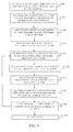
FIG. 5 is a flow chart depicting an exemplary method for adjustment and operation of the TMD. - Embodiments disclosed herein provide a TMD having a resilient element such as a spring, a moving mass and a lossy element to introduce damping. The spring is designed to guide the motion of the TMD for reciprocation on a desired axis through the TMD. If a shorted voice coil combined with a magnet is used as the lossy element, an added benefit can be realized by changing the resistance across the coil to change the damping. TMDs with voice coil loss mechanisms are commercially available from CSA/Moog (http://www.csaengineering.com/products-services/tuned-mass-dampers-absorbers/tmd-products/). The self-tuning TMD disclosed in the present embodiment uses the voice coil / magnet combination as both an actuator and a lossy element which enables an innovative stiffness adjustment mechanism.
- The basic components of the self-tuning TMD are shown in
FIGs. 1A-1C . Avoice coil 10 with acore 12 is supported in aframe 14. For the embodiment shown, the frame employs atop flange 15a and abottom flange 15b spaced apart and connected bycolumns 15c. While shown for the embodiment in the drawings as an open frame, a closed housing may be employed in alternative embodiments. Amagnet 16, supported by resilient elements formed bysemi-helical flexures coil 10 and is movable relative to the housing via thevoice coil 10. Themagnet 16 provides the moving mass for the TMD that reciprocates concentrically on anaxis 20. Theflexures pillars 20 extending from theframe 14. The plurality of flexures have a first end extending from themagnet 16 and anarm 19 releasably coupled to theframe 14. For the embodiment shown, theflexures symmetrical arms 19. In alternative embodiments the flexures may be supported by various attachments on thecolumns 15c replacing thepillars 20 and alternative numbers of arms and associated pillars may be employed for the flexures to supportmagnet 16. - The
voice coil 10 can be actively powered and used to move themagnet 16 up or down from the neutral position shown inFIG. 1B . A large voltage applied to the voice coil by a control system, to be described in greater detail subsequently, pushesmagnet 16 axially to engage bearingrace ramps magnet 16, againstbearing guides frame 14. Axial engagement of the ramps and guides causes rotation of themagnet 16. Rotation of themagnet 16 causes rotation of the attachedflexures magnet 16 is pushed downwardly in the depiction in the drawings as shown inFIG. 2A , contact between the bearing race ramps 22b and the bearing guides 24b force the magnet to turn in a counter clockwise direction. If themagnet 16 is pushed upwardly in the depiction in the drawings as shown inFIG. 2B , contact between the bearing race ramps 22a and bearing guides 24a force the magnet to turn in a clockwise direction. Theflexures magnet 16 with respect to theframe 14, incorporatearcuate slots 26 which are substantially concentric aroundaxis 20 and engagepins 28 extending from thepillars 20. Thepins 28 are received within theslots 26, and each pin is positionable in theslot 26 for adjustment of an effective length of said flexure 18. Normally closed solenoids 30 lock down clamps 31 to secure the flexures when no voltage is applied and release the clamps when a voltage is applied. When the solenoids are locked, theflexures slots 26 which centers the magnet and allows it to vibrate relative to thevoice coil 10. The natural or resonant frequency of the vibration of the magnet mass in the TMD can be changed through changing the effective length of theflexures pins 28 and clamps 31 with respect to theslots 26. A clockwise motion of themagnet 16 lengthens the flexure along a range of theslots 26 terminating at adistal end 32 as shown inFIG. 3A , where a counter clockwise motion of themagnet 16 shortens the flexure along the range of the slots terminating at aproximal end 34 as shown inFIG. 3B . Clockwise rotation may be enabled viafirst ramps 22a attached to themagnet 16, which when moved in a first direction engagefirst guide elements 24a to cause themagnet 16 andflexural members magnet 16, which when moved in a second direction engagesecond guide elements 24b to cause themagnet 16 andflexural members clamp 31 is actuated by asolenoid 30 to clamp on at least one flexural member, and is configured to allow the magnet16 andflexural members solenoid 30 may be powered for activation in the first state, and deactivated in the second state whereby the clamp is engaged in a failure condition of the solenoid. Accordingly, rotation in the first direction lengthens the effective length of the flexural members and rotation in the second direction shortens the effective length of the flexural members, such that the tuned mass damper frequency is adjustable by changing the effective length of the flexure members. The frequency is adjustable over a range based on the location of theclamps 31 and pins 28 in theslots 26. When a large voltage is applied to the actuator to clock themagnet 16, a voltage is also applied by the control system to thesolenoids 30 releasing theclamps 31 to allow sliding of the flexures relative to thepins 28 supported by thepillars 20. - The damping of the TMD can be changed by varying resistance across the
voice coil 10 using, for example, a digitally programmable analog resistor. Increasing the resistance makes the inductive interaction between thevoice coil 10 andmagnet 16 more lossy while decreasing the resistance makes the interaction less lossy. A control system as shown inFIG. 4 may be employed to actively control thevoice coil 10 for clocking themagnet 16 to alter the resonant frequency of the TMD or to cause excitation of the magnet allowing the TMD to act like a shaker or a modal hammer. Acontrol computer 402 employs control algorithms to act on inputs received through ancontrol interface 403 which may include an analog to digital (A/D) and digital to analog (D/A)interface 404 and provides control output through avoice coil amplifier 406 to actively position or drive thevoice coil 10 as previously described. The control system may include encoded instructions therein for calculating an optimum frequency range based on input from the at least one accelerometer. The control system is configured to activate the at least one solenoid actuatedclamp 31 and control thevoice coil 12 to rotate the magnet to adjust theflexural members solenoid amplifier 408 is connected to thecontrol computer 402 to controllably release thesolenoids 30 an associated clamps 31 as previously described. Varioussignal conditioning components 410 may also be employed. Aremovable tether 412 couples the control system components to theTMD 400 with connections to thesolenoids 30 andvoice coil 10 and additional connection to at least oneaccelerometer 414 on thehost structure 416, at least oneaccelerometer 418a associated with themagnet 16 and at least oneaccelerometer 418b mounted to theframe 14. Data from the accelerometers is processed through thesignal conditioning elements 410 and A/D in the A/D & D/A interface 404. A control connection in thetether 412 to avariable resistor 420, which is connected across thevoice coil 10, allows adjustment of the lossy characteristics of the TMD under control of thecontrol computer 402 through the D/A in the A/D & D/A interface 404. - Given a frequency band of interest associated with the host structure, the self-tuning TMD can be adjusted to a selected test frequency well below the lowest frequency in the band and measure a collocated transfer function between current into the voice coil and acceleration of the base. A current mode amplifier as one of the
signal conditioning elements 410 would be required. Alternatively, a transfer function between voltage into the voice coil and the acceleration of the base could be used, however, this transfer function will be affected by addition of some damping through back EMF. The transfer function selected will give insight into the uncoupled behavior of the host structure and may be used as the starting point for an algorithm to tune the TMD. The measured transfer function will show lightly damped modes that are good candidates for damping to reduce the host structure response. The control system is configured to analyze a frequency band that includes more than one lightly damped resonance frequency and determine an optimum frequency and damping to minimize the effect of vibration. This technique may also be applied with multiple TMDs (shown aselements 400 with associatedinterfaces 403 inFIG. 4 ) mounted to the structure with at least one TMD connected for driving the voice coil as an actuator. With all of the TMDs tuned to the selected test frequency, the accelerometers in all TMDs could then be sampled to collect response data and the determination by the control system may be made for optimization of all of the TMDs to reduce response to a disturbance at or near the TMD which was driven as the actuator. Each TMD may then be adjusted using the voice coil to clock the magnets in each TMD as described above and the control computer may adjust the programmable resistance for each TMD to provide the desired response. - As shown in
FIG. 5 , a self-tuning TMD having the structure of the described embodiment is attached to a host structure at a location with an anticipated large dynamic response,step 502. A tether is then attached to at least one TMD to provide power to the voice coil and solenoids and to receive signals from accelerometers mounted on the TMD frame, magnet and host structure,step 504. A control system is employed to release the flexure clamps and the TMD is adjusted by using the voice coil to urge the magnet and ramps into contact with the bearing guides to adjust the frequency of the TMD below the frequency band of interest and reclamp the flexures,step 506. The control system then actuates the voice coil as a shaker and measures the resulting uncoupled host transfer function,step 508. The uncoupled host transfer function and a predetermined tuning logic are employed to determine a preferred TMD frequency and damping,step 510. The control system is then employed to again release the flexure clamps and the TMD is adjusted by using the voice coil to urge the magnet and ramps into contact with the bearing guides to adjust flexure length to obtain the desired frequency of the TMD and reclamp the flexures,step 512. The control system them alters voltage on a digitally programmable analog resistor across the voice coil to set the desired damping,step 514. The control system may then again activate the voice coil as a shaker and measure the resulting coupled host transfer function with the accelerometers to compare to the predicted transfer function,step 516.Steps 506 through 516 may then be repeated until a convergence criteria is satisfied,step 518. The tether is then removed from the TMD,step 520 and the TMD is ready for autonomous operation for dynamically damping the host structure. While the steps herein are described with respect to at least one TMD, a plurality of TMDs may be connected, activated, measured and tuned as a group to be optimized for desired damping of the structure to which the TMDs are attached as previously described. A single TMD of the plurality may be activated as the shaker while all TMDs in the plurality may be measured and tuned. - Further, the disclosure comprises embodiments according to the following clauses:
- Clause 1. A tuned mass damper comprising:
- a frame,
- a voice coil supported in the frame;
- a magnet concentric with the voice coil and movable relative to the housing via the voice coil; and,
- a plurality of flexures having a first end extending from the magnet and an arm releasably coupled to the frame, said flexures adjustable for a desired frequency of reciprocation of the magnet.
- Clause 2. The tuned mass damper as defined in Clause 1 wherein each flexure incorporates a slot in the arm, said slot receiving a pin supported from the frame said pin positionable in the slot for adjustment of an effective length of said flexure.
- Clause 3. The tuned mass damper as defined in Clause 2 further comprising:
- first ramps attached to the magnet which when moved in a first direction engage first guide elements to cause the magnet and flexural members to rotate in a clockwise direction;
- second ramps attached to the magnet which when moved in a second direction engage second guide elements to cause the magnet and flexural members to rotate in a counter-clockwise direction.
- Clause 4. The tuned mass damper as defined in Clause 3 further comprising:
- at least one clamp actuated by a solenoid on at least one flexural member and configured to allow the magnet and flexural members to rotate when the solenoid is in a first state, and to clamp the flexural members in a fixed position when the solenoid is in a second state,
- wherein rotation in the first direction lengthens the effective length of the flexural members and rotation in the second direction shortens the effective length of the flexural members, such that the tuned mass damper frequency is adjustable by changing the effective length of the flexure members.
- Clause 5. The tuned mass damper as defined in any preceding Clause further comprising at least one accelerometer disposed on the magnet.
- Clause 6. The tuned mass damper as defined in Clause 5 further comprising a control system having encoded instructions therein for calculating an optimum frequency range based on input from the at least one accelerometer, the control system configured to activate the at least one solenoid actuated clamp and control the voice coil to rotate the magnet to adjust the flexural members to an effective length corresponding to the calculated frequency. Optionally, the control system is configured to analyze a frequency band that includes more than one lightly damped resonance frequency and determine an optimum frequency and damping to minimize the effect of vibration.
- Clause 7. The tuned mass damper of Clause 6, further comprising a variable resistance in series with the voice coil, said variable resistance responsive to the control system to adjust the damping of the tuned mass damper.
- Clause 8. The tuned mass damper as defined in Clause 6 or Clause 7 further comprising a tether removably connecting the control system to the voice coil and the at least one accelerometer.
- Clause 9. The tuned mass damper as defined in any one of Clauses 4 to 8 wherein the solenoid is powered for activation in the first state and deactivated in the second state whereby the clamp is engaged in a failure condition of the solenoid.
-
Clause 10. A method for operation of a tunable mass damper (TMD) comprising:- attaching at least one TMD to a structure, the TMD having a voice coil and concentric magnet as a moving mass supported by flexures to a host structure at a location with an anticipated large dynamic response;
- releasing flexure clamps;
- adjusting flexure length on the TMD by using the voice coil to urge the magnet and associated ramps into contact with bearing guides to rotate the magnet and flexures to obtain a desired frequency of the TMD;
- reclamping the flexures for operation of the TMD.
- Clause 11. The method as defined in
Clause 10 further comprising:- adjusting the flexure length by using the voice coil to urge the magnet and ramps into contact with the bearing guides to adjust the frequency of the TMD below the frequency band of interest;
- reclamping the flexures;
- actuating the voice coil as a shaker;
- measuring the resulting uncoupled host transfer function; and,
- employing the uncoupled host transfer function and a predetermined tuning logic to determine a preferred TMD frequency and damping.
-
Clause 12. The method as defined in Clause 11 further comprising:- activating the voice coil as a shaker;
- measuring the resulting coupled host transfer function with the accelerometers to compare to the predicted transfer function; and
- repeating the steps of adjusting flexure length, activating the voice coil as a shaker and measuring the resulting coupled host transfer function to obtain a desired frequency of the TMD until a convergence criteria is satisfied.
- Clause 13. The method as defined in
Clause 12 further comprising attaching a tether to the TMD to provide power to the voice coil and solenoids and to receive signals from accelerometers mounted on the TMD frame, magnet and host structure. -
Clause 14. The method as defined in Clause 13 further comprising removing the tether from the TMD for autonomous operation pf the TMD for dynamically damping the host structure. - Clause 15. The method as defined in Clause 13 further comprising altering voltage on a digitally programmable analog resistor across the voice coil to set a desired damping.
-
Clause 16. The method as defined in Clause 11 wherein the at least one TMD comprises a plurality of TMDs and the step of activating the voice coil comprises activating the voice coil of a selected one of the TMDs as a shaker, the step of measuring the resulting uncoupled host transfer function comprises measuring the resulting uncoupled host transfer function for each of the TMDs, the steps of releasing the flexure clamps, adjusting the flexure length and reclamping the flexure clamps are performed for each TMD. - Clause 17. A structural damping system comprising the tuned mass damper of any one of Clauses 1 to 9, further including:
- a host structure having a location with anticipated high dynamic response;
- at least one accelerometer attached to the voice coil;
- a control system having encoded instructions therein for calculating an optimum frequency range based on input from the at least one accelerometer, the control system configured to control the voice coil to rotate the magnet to adjust the flexural members to an effective length corresponding to the calculated frequency.
- Clause 18. The structural damping system as defined in Clause 17, wherein the control system is configured to analyze a frequency band that includes more than one lightly damped resonance frequency and determine an optimum frequency and damping to minimize the effect of vibration.
-
Clause 19. The structural damping system as defined in Clause 17 wherein each flexure incorporates a slot in the arm, said slot receiving a pin supported from the frame said pin positionable in the slot for adjustment of an effective length of said flexure further comprising:- first ramps attached to the magnet which when moved in a first direction engage first guide elements to cause the magnet and flexural members to rotate in a clockwise direction;
- second ramps attached to the magnet which when moved in a second direction engage second guide elements to cause the magnet and flexural members to rotate in a counter-clockwise direction;
- at least one clamp actuated by a solenoid on at least one flexural member and configured to allow the magnet and flexural members to rotate when the solenoid is in a first state, and to clamp the flexural members in a fixed position when the solenoid is in a second state,
-
Clause 20. The structural damping system as defined in claim 17 where in the at least one TMD comprises a plurality of TMDs. - Having now described various embodiments of the disclosure in detail as required by the patent statutes, those skilled in the art will recognize modifications and substitutions to the specific embodiments disclosed herein. Such modifications are within the scope and intent of the present disclosure as defined in the following claims.
Claims (15)
- A tuned mass damper comprising:a frame (14),a voice coil (10) supported in the frame (14);a magnet (16) concentric with the voice coil (10) and movable relative to the housing via the voice coil (10); and,a plurality of flexures (18a and 18b) having a first end extending from the magnet (16) and an arm (19) releasably coupled to the frame (14), said flexures (18a and 18b) adjustable for a desired frequency of reciprocation of the magnet (16).
- The tuned mass damper as defined in claim 1 wherein each flexure incorporates a slot in the arm (19), said slot receiving a pin supported from the frame (14) said pin positionable in the slot for adjustment of an effective length of said flexure.
- The tuned mass damper as defined in claim 2 further comprising:first ramps (22a) attached to the magnet (16) which when moved in a first direction engage first guide elements (24a) to cause the magnet (16) and flexural members (18a and 18b) to rotate in a clockwise direction;second ramps (22b) attached to the magnet (16) which when moved in a second direction engage second guide elements (24b) to cause the magnet (16) and flexural members (18a and 18b) to rotate in a counter-clockwise direction.
- The tuned mass damper as defined in claim 3 further comprising:at least one clamp (31) actuated by a solenoid (30) on at least one flexural member (18a) and configured to allow the magnet (16) and flexural members (18a and 18b) to rotate when the solenoid (30) is in a first state, and to clamp (31) the flexural members (18a and 18b) in a fixed position when the solenoid (30) is in a second state,wherein rotation in the first direction lengthens the effective length of the flexural members (18a and 18b) and rotation in the second direction shortens the effective length of the flexural members (18a and 18b), such that the tuned mass damper frequency is adjustable by changing the effective length of the flexure members (18a and 18b).
- The tuned mass damper as defined in any preceding claim further comprising at least one accelerometer (418b) disposed on the magnet (16).
- The tuned mass damper (400) as defined in claim 5 further comprising a control system (402) having encoded instructions therein for calculating an optimum frequency range based on input from the at least one accelerometer (418b), the control system (402) configured to activate the at least one solenoid (30) actuated clamp (31) and control the voice coil (10) to rotate the magnet (16) to adjust the flexural members (18a and 18b) to an effective length corresponding to the calculated frequency , wherein the control system (402) is configured to analyze a frequency band that includes more than one lightly damped resonance frequency and determine an optimum frequency and damping to minimize the effect of vibration.
- The tuned mass damper (400) of claim 6, further comprising a variable resistance in series with the voice coil (10), said variable resistance responsive to the control system (402) to adjust the damping of the tuned mass damper (400).
- The tuned mass damper (400) as defined in claim 6 or claim 7 further comprising a tether (412) removably connecting the control system (402) to the voice coil (10) and the at least one accelerometer (414).
- A method for operation of a tunable mass damper (TMD) comprising:attaching at least one TMD to a structure, the TMD having a voice coil (10) and concentric magnet (16) as a moving mass supported by flexures (18a and 18b) to a host structure (416) at a location with an anticipated large dynamic response;releasing flexure clamps (31);adjusting flexure length on the TMD by using the voice coil (10) to urge the magnet (16) and associated ramps (22a or 22b) into contact with bearing guides to rotate the magnet (16) and flexures (18a and 18b) to obtain a desired frequency of the TMD;reclamping the flexures (18a and 18b) for operation of the TMD.
- The method as defined in claim 9 further comprising:adjusting the flexure length by using the voice coil (10) to urge the magnet (16) and ramps (22a or 22b) into contact with the bearing guides (24b) to adjust the frequency of the TMD below the frequency band of interest;reclamping the flexures (18a and 18b);actuating the voice coil (10) as a shaker;measuring the resulting uncoupled host transfer function; and,employing the uncoupled host transfer function and a predetermined tuning logic to determine a preferred TMD frequency and damping.
- The method as defined in claim 10 further comprising:activating the voice coil (10) as a shaker;measuring the resulting coupled host transfer function with the accelerometers to compare to the predicted transfer function; andrepeating the steps of adjusting flexure length, activating the voice coil (10) as a shaker and measuring the resulting coupled host transfer function to obtain a desired frequency of the TMD until a convergence criteria is satisfied.
- The method as defined in claim 11 further comprising attaching a tether (412) to the TMD to provide power to the voice coil (10) and solenoids (30) and to receive signals from accelerometers (418) mounted on the TMD frame (14), magnet (16) and host structure (416).
- The method as defined in claim 12 further comprising altering voltage on a digitally programmable analog resistor (420) across the voice coil (10) to set a desired damping.
- A structural damping system comprising the tuned mass damper of any one of claims 1 to 8, further including:a host structure (416) having a location with anticipated high dynamic response;at least one accelerometer (418a) attached to the voice coil (10);a control system (402) having encoded instructions therein for calculating an optimum frequency range based on input from the at least one accelerometer (418a), the control system (402) configured to control the voice coil (10) to rotate the magnet (16) to adjust the flexural members (18a and 18b) to an effective length corresponding to the calculated frequency , wherein the control system (402) is configured to analyze a frequency band that includes more than one lightly damped resonance frequency and determine an optimum frequency and damping to minimize the effect of vibration.
- The structural damping system as defined in claim 14 wherein each flexure incorporates a slot (26) in the arm (19), said slot (26) receiving a pin (28) supported from the frame (14) said pin (28) positionable in the slot (26) for adjustment of an effective length of said flexure further comprising:first ramps (22a) attached to the magnet (16) which when moved in a first direction engage first guide elements (24a) to cause the magnet (16) and flexural members (18a and 18b) to rotate in a clockwise direction;second ramps (22b) attached to the magnet (16) which when moved in a second direction engage second guide elements (24b) to cause the magnet (16) and flexural members (18a and 18b) to rotate in a counter-clockwise direction;at least one clamp (31) actuated by a solenoid (30) on at least one flexural member (18a or 18b) and configured to allow the magnet (16) and flexural members (18a and 18b) to rotate when the solenoid (30) is in a first state, and to clamp (31) the flexural members (18a and 18b) in a fixed position when the solenoid (30) is in a second state,wherein rotation in the first direction lengthens the effective length of the flexural members (18a and 18b) and rotation in the second direction shortens the effective length of the flexural members (18a and 18b), such that the tuned mass damper frequency is adjustable by changing the effective length of the flexure members (18a and 18b).
Applications Claiming Priority (1)
| Application Number | Priority Date | Filing Date | Title |
|---|---|---|---|
| US14/840,024 US9587699B1 (en) | 2015-08-30 | 2015-08-30 | Self-tuning tunable mass dampers |
Publications (2)
| Publication Number | Publication Date |
|---|---|
| EP3135950A1 true EP3135950A1 (en) | 2017-03-01 |
| EP3135950B1 EP3135950B1 (en) | 2018-08-15 |
Family
ID=56134106
Family Applications (1)
| Application Number | Title | Priority Date | Filing Date |
|---|---|---|---|
| EP16172855.5A Active EP3135950B1 (en) | 2015-08-30 | 2016-06-03 | Self-tuning tunable mass dampers and method for operation |
Country Status (4)
| Country | Link |
|---|---|
| US (1) | US9587699B1 (en) |
| EP (1) | EP3135950B1 (en) |
| JP (1) | JP6466378B2 (en) |
| CN (1) | CN106481734B (en) |
Cited By (4)
| Publication number | Priority date | Publication date | Assignee | Title |
|---|---|---|---|---|
| WO2021052963A1 (en) * | 2019-09-17 | 2021-03-25 | Fraunhofer-Gesellschaft zur Förderung der angewandten Forschung eingetragener Verein | Device for autonomously and variably adjusting rigidity in at least two spatial directions, corresponding method, and corresponding application |
| CN114312965A (en) * | 2022-02-28 | 2022-04-12 | 东风汽车有限公司东风日产乘用车公司 | Steering wheel vibration frequency adjusting device and method |
| CN115419183A (en) * | 2022-08-31 | 2022-12-02 | 湖南省潇振工程科技有限公司 | Tuned mass damper and damper frequency modulation method |
| CN120404033A (en) * | 2025-07-04 | 2025-08-01 | 新虹元科技(江苏)有限公司 | Raised floor seismic detection device |
Families Citing this family (18)
| Publication number | Priority date | Publication date | Assignee | Title |
|---|---|---|---|---|
| US9863839B2 (en) * | 2015-11-18 | 2018-01-09 | The Boeing Company | Positioner for electrodynamic shaker |
| KR101722669B1 (en) * | 2016-06-16 | 2017-04-12 | 주식회사 천일 | Earthquake-Resistant Light Tower with the Tuned Mass Damper |
| US9992890B1 (en) * | 2016-12-07 | 2018-06-05 | Raytheon Company | Modules and systems for damping excitations within fluid-filled structures |
| US10295011B2 (en) | 2017-10-06 | 2019-05-21 | The Boeing Company | Systems and tuned magnetic dashpots for using inductor(s) in magnetic skyhook damper isolation |
| US10539201B2 (en) | 2017-11-13 | 2020-01-21 | The Boeing Company | Semi-active tuned mass damper to eliminate limit-cycle oscillation |
| IT201800007173A1 (en) | 2018-07-13 | 2020-01-13 | System of identification and active control of vibrations in a structure, and related method | |
| CN109573102B (en) * | 2018-11-30 | 2020-09-18 | 北京宇航系统工程研究所 | Whole cabin vibration damper without resonance peak |
| DE102019216009B4 (en) * | 2019-10-17 | 2025-12-04 | Volkswagen Aktiengesellschaft | vibration damper |
| CN111021568A (en) * | 2019-11-29 | 2020-04-17 | 中国电力科学研究院有限公司 | Tuned mass damper for controlling eddy current through vibration of fan tower |
| CN112857722B (en) * | 2021-01-21 | 2023-05-05 | 中国电建集团华东勘测设计研究院有限公司 | Vibration table test acceleration amplifying device with variable rigidity, mass and damping |
| AU2022346224A1 (en) * | 2021-09-15 | 2024-03-28 | Bae Systems Plc | Resonator, resonator array, vibration control system and method |
| CN114662241B (en) * | 2022-04-02 | 2024-10-22 | 哈尔滨工业大学 | A unified design method for TMDI and TMD based on Kramers-Kronig relationship |
| CN115234595B (en) * | 2022-07-19 | 2025-06-24 | 西安交通大学 | A double-helix low-frequency vibration absorbing device |
| WO2024084107A1 (en) * | 2022-10-20 | 2024-04-25 | Universidad Pública de Navarra | Shock absorber with adjustable elastic constant |
| CN115822118B (en) * | 2022-12-14 | 2025-05-02 | 湖南大学重庆研究院 | A low-frequency vibration isolator with an ultra-wide quasi-zero stiffness range |
| CN117005295B (en) * | 2023-08-31 | 2025-11-18 | 湖南悦之佳科技发展有限公司 | Damped Stepless Adjustable Eddy Current Tuned Mass Damper and its Installation and Adjustment Method |
| CN119312633B (en) * | 2024-09-30 | 2025-06-27 | 华东交通大学 | MTMD vibration reduction system for turnout frog area under complex load condition and control method thereof |
| CN119616085B (en) * | 2024-12-09 | 2026-02-10 | 重庆交通大学 | A multi-stage semi-active magnetoresistive damper with recyclable energy |
Citations (2)
| Publication number | Priority date | Publication date | Assignee | Title |
|---|---|---|---|---|
| DE102010029910A1 (en) * | 2010-06-10 | 2011-12-15 | Bayerische Motoren Werke Aktiengesellschaft | Active oscillation damper for motor car, has single spring element units implemented in shape memory alloy of upper and lower spring elements |
| DE102010030700A1 (en) * | 2010-06-30 | 2012-01-05 | Bayerische Motoren Werke Aktiengesellschaft | Active oscillation damper for arranging at structure of motor car, has spring elements, where spring stiffness of spring elements of spring mass system of damper and natural frequency of spring mass system of damper are slightly changed |
Family Cites Families (11)
| Publication number | Priority date | Publication date | Assignee | Title |
|---|---|---|---|---|
| US4922159A (en) * | 1988-05-09 | 1990-05-01 | Harris Corporation | Linear precision actuator with accelerometer feedback |
| GB9107451D0 (en) * | 1991-04-09 | 1991-05-22 | Yang Tai Her | The principle and structure of actively driving or centrifugal linear following dynamic flywheel effect |
| DE4301845C1 (en) * | 1993-01-23 | 1994-03-31 | Freudenberg Carl Fa | Active vibration damper for oscillating machine part - includes inertial, reciprocatable mass carrying plate via coupling spring and fixable at machine part |
| DE19823716A1 (en) * | 1998-05-27 | 1999-12-02 | Btr Avs Technical Centre Gmbh | Active vibration absorber |
| DE19839464C2 (en) * | 1998-08-29 | 2001-07-05 | Contitech Formteile Gmbh | Electrodynamic actuator with oscillating spring-mass system |
| KR101184284B1 (en) * | 2010-06-23 | 2012-09-26 | 주식회사 파브코 | Active dynamic vibration absorber apparatus for vehicle |
| DE102010037922A1 (en) * | 2010-10-01 | 2012-04-05 | Contitech Vibration Control Gmbh | actuator |
| ES2520466T3 (en) * | 2012-09-13 | 2014-11-11 | Ideko, S. Coop | Inertial shock absorber for vibration suppression in machine tools |
| JP6022287B2 (en) * | 2012-09-28 | 2016-11-09 | 住友理工株式会社 | Anti-vibration linear actuator and active vibration damper using it |
| JP6302678B2 (en) * | 2014-01-16 | 2018-03-28 | 住友理工株式会社 | Active vibration control device |
| CN104806693B (en) * | 2015-04-30 | 2017-08-01 | 上海交通大学 | Intelligent Adaptive Vibration Absorber, Array Integration Device and Its Application |
-
2015
- 2015-08-30 US US14/840,024 patent/US9587699B1/en active Active
-
2016
- 2016-06-03 EP EP16172855.5A patent/EP3135950B1/en active Active
- 2016-08-18 JP JP2016160452A patent/JP6466378B2/en active Active
- 2016-08-26 CN CN201610737119.6A patent/CN106481734B/en active Active
Patent Citations (2)
| Publication number | Priority date | Publication date | Assignee | Title |
|---|---|---|---|---|
| DE102010029910A1 (en) * | 2010-06-10 | 2011-12-15 | Bayerische Motoren Werke Aktiengesellschaft | Active oscillation damper for motor car, has single spring element units implemented in shape memory alloy of upper and lower spring elements |
| DE102010030700A1 (en) * | 2010-06-30 | 2012-01-05 | Bayerische Motoren Werke Aktiengesellschaft | Active oscillation damper for arranging at structure of motor car, has spring elements, where spring stiffness of spring elements of spring mass system of damper and natural frequency of spring mass system of damper are slightly changed |
Cited By (6)
| Publication number | Priority date | Publication date | Assignee | Title |
|---|---|---|---|---|
| WO2021052963A1 (en) * | 2019-09-17 | 2021-03-25 | Fraunhofer-Gesellschaft zur Förderung der angewandten Forschung eingetragener Verein | Device for autonomously and variably adjusting rigidity in at least two spatial directions, corresponding method, and corresponding application |
| CN114312965A (en) * | 2022-02-28 | 2022-04-12 | 东风汽车有限公司东风日产乘用车公司 | Steering wheel vibration frequency adjusting device and method |
| CN114312965B (en) * | 2022-02-28 | 2023-06-02 | 东风汽车有限公司东风日产乘用车公司 | Steering wheel vibration frequency adjusting device and method |
| CN115419183A (en) * | 2022-08-31 | 2022-12-02 | 湖南省潇振工程科技有限公司 | Tuned mass damper and damper frequency modulation method |
| CN115419183B (en) * | 2022-08-31 | 2023-10-20 | 湖南省潇振工程科技有限公司 | Tuned mass damper and damper frequency modulation method |
| CN120404033A (en) * | 2025-07-04 | 2025-08-01 | 新虹元科技(江苏)有限公司 | Raised floor seismic detection device |
Also Published As
| Publication number | Publication date |
|---|---|
| US20170058984A1 (en) | 2017-03-02 |
| US9587699B1 (en) | 2017-03-07 |
| EP3135950B1 (en) | 2018-08-15 |
| JP6466378B2 (en) | 2019-02-06 |
| CN106481734B (en) | 2019-11-01 |
| CN106481734A (en) | 2017-03-08 |
| JP2017044341A (en) | 2017-03-02 |
Similar Documents
| Publication | Publication Date | Title |
|---|---|---|
| EP3135950B1 (en) | Self-tuning tunable mass dampers and method for operation | |
| US9733151B2 (en) | System and method for accelerating a device | |
| KR101240170B1 (en) | Motor driving device | |
| JP6157026B2 (en) | System, apparatus, and method for resonator and Coriolis axis control in a vibrating gyroscope | |
| US7781935B2 (en) | Energy conversion system with variable airgap distance and energy recovery method | |
| KR20200073126A (en) | Method for calibrating frequency of driving voltage waveform for linear resonance device and related device | |
| JP2008536470A (en) | Conversion of mechanical vibration energy to electrical energy | |
| JP2017044341A5 (en) | ||
| EP3209860B1 (en) | Improvements in or relating to down hole surveying | |
| JP2001041846A (en) | Model support method and device for wind tunnel test | |
| CN110073436B (en) | Active vibration damping system for absorbing vibrations of a vibrating component, motor vehicle having such an active vibration damping system and method for operating an active vibration damping system | |
| EP2286110A1 (en) | A vibration sensor and a system to isolate vibrations | |
| US20120063019A1 (en) | Control method for a voice coil motor and lens focusing system using the same | |
| KR20060006269A (en) | Mass measurement system and method by measuring frequency change of oscillator | |
| Hunstig et al. | High-velocity operation of piezoelectric inertia motors: experimental validation | |
| Griffin et al. | Self-tuning tunable mass dampers | |
| US9616565B2 (en) | Adjusting parameters of a dynamical robot model | |
| US20240233499A9 (en) | Haptic output device and method for providing haptic output | |
| KR101062238B1 (en) | Rotary drive controller | |
| JP2005276118A (en) | Active floor vibration control device | |
| CN116147756B (en) | Detection method and detection device for resonant frequency of linear motor | |
| KR20090015833A (en) | Magnetic disk device and magnetic head control method | |
| JPWO2008072307A1 (en) | Balance correction apparatus and method | |
| JP4139658B2 (en) | Mechanism control system design method | |
| KR20110016317A (en) | Portable excitation device |
Legal Events
| Date | Code | Title | Description |
|---|---|---|---|
| PUAI | Public reference made under article 153(3) epc to a published international application that has entered the european phase |
Free format text: ORIGINAL CODE: 0009012 |
|
| STAA | Information on the status of an ep patent application or granted ep patent |
Free format text: STATUS: REQUEST FOR EXAMINATION WAS MADE |
|
| 17P | Request for examination filed |
Effective date: 20160603 |
|
| AK | Designated contracting states |
Kind code of ref document: A1 Designated state(s): AL AT BE BG CH CY CZ DE DK EE ES FI FR GB GR HR HU IE IS IT LI LT LU LV MC MK MT NL NO PL PT RO RS SE SI SK SM TR |
|
| AX | Request for extension of the european patent |
Extension state: BA ME |
|
| GRAP | Despatch of communication of intention to grant a patent |
Free format text: ORIGINAL CODE: EPIDOSNIGR1 |
|
| STAA | Information on the status of an ep patent application or granted ep patent |
Free format text: STATUS: GRANT OF PATENT IS INTENDED |
|
| INTG | Intention to grant announced |
Effective date: 20180202 |
|
| GRAS | Grant fee paid |
Free format text: ORIGINAL CODE: EPIDOSNIGR3 |
|
| GRAJ | Information related to disapproval of communication of intention to grant by the applicant or resumption of examination proceedings by the epo deleted |
Free format text: ORIGINAL CODE: EPIDOSDIGR1 |
|
| GRAL | Information related to payment of fee for publishing/printing deleted |
Free format text: ORIGINAL CODE: EPIDOSDIGR3 |
|
| STAA | Information on the status of an ep patent application or granted ep patent |
Free format text: STATUS: REQUEST FOR EXAMINATION WAS MADE |
|
| GRAR | Information related to intention to grant a patent recorded |
Free format text: ORIGINAL CODE: EPIDOSNIGR71 |
|
| STAA | Information on the status of an ep patent application or granted ep patent |
Free format text: STATUS: GRANT OF PATENT IS INTENDED |
|
| INTC | Intention to grant announced (deleted) | ||
| GRAA | (expected) grant |
Free format text: ORIGINAL CODE: 0009210 |
|
| STAA | Information on the status of an ep patent application or granted ep patent |
Free format text: STATUS: THE PATENT HAS BEEN GRANTED |
|
| INTG | Intention to grant announced |
Effective date: 20180702 |
|
| AK | Designated contracting states |
Kind code of ref document: B1 Designated state(s): AL AT BE BG CH CY CZ DE DK EE ES FI FR GB GR HR HU IE IS IT LI LT LU LV MC MK MT NL NO PL PT RO RS SE SI SK SM TR |
|
| REG | Reference to a national code |
Ref country code: CH Ref legal event code: EP Ref country code: GB Ref legal event code: FG4D Ref country code: AT Ref legal event code: REF Ref document number: 1030147 Country of ref document: AT Kind code of ref document: T Effective date: 20180815 |
|
| REG | Reference to a national code |
Ref country code: IE Ref legal event code: FG4D |
|
| REG | Reference to a national code |
Ref country code: DE Ref legal event code: R096 Ref document number: 602016004699 Country of ref document: DE |
|
| REG | Reference to a national code |
Ref country code: NL Ref legal event code: MP Effective date: 20180815 |
|
| REG | Reference to a national code |
Ref country code: LT Ref legal event code: MG4D |
|
| REG | Reference to a national code |
Ref country code: AT Ref legal event code: MK05 Ref document number: 1030147 Country of ref document: AT Kind code of ref document: T Effective date: 20180815 |
|
| PG25 | Lapsed in a contracting state [announced via postgrant information from national office to epo] |
Ref country code: LT Free format text: LAPSE BECAUSE OF FAILURE TO SUBMIT A TRANSLATION OF THE DESCRIPTION OR TO PAY THE FEE WITHIN THE PRESCRIBED TIME-LIMIT Effective date: 20180815 Ref country code: RS Free format text: LAPSE BECAUSE OF FAILURE TO SUBMIT A TRANSLATION OF THE DESCRIPTION OR TO PAY THE FEE WITHIN THE PRESCRIBED TIME-LIMIT Effective date: 20180815 Ref country code: IS Free format text: LAPSE BECAUSE OF FAILURE TO SUBMIT A TRANSLATION OF THE DESCRIPTION OR TO PAY THE FEE WITHIN THE PRESCRIBED TIME-LIMIT Effective date: 20181215 Ref country code: FI Free format text: LAPSE BECAUSE OF FAILURE TO SUBMIT A TRANSLATION OF THE DESCRIPTION OR TO PAY THE FEE WITHIN THE PRESCRIBED TIME-LIMIT Effective date: 20180815 Ref country code: SE Free format text: LAPSE BECAUSE OF FAILURE TO SUBMIT A TRANSLATION OF THE DESCRIPTION OR TO PAY THE FEE WITHIN THE PRESCRIBED TIME-LIMIT Effective date: 20180815 Ref country code: GR Free format text: LAPSE BECAUSE OF FAILURE TO SUBMIT A TRANSLATION OF THE DESCRIPTION OR TO PAY THE FEE WITHIN THE PRESCRIBED TIME-LIMIT Effective date: 20181116 Ref country code: NO Free format text: LAPSE BECAUSE OF FAILURE TO SUBMIT A TRANSLATION OF THE DESCRIPTION OR TO PAY THE FEE WITHIN THE PRESCRIBED TIME-LIMIT Effective date: 20181115 Ref country code: BG Free format text: LAPSE BECAUSE OF FAILURE TO SUBMIT A TRANSLATION OF THE DESCRIPTION OR TO PAY THE FEE WITHIN THE PRESCRIBED TIME-LIMIT Effective date: 20181115 Ref country code: AT Free format text: LAPSE BECAUSE OF FAILURE TO SUBMIT A TRANSLATION OF THE DESCRIPTION OR TO PAY THE FEE WITHIN THE PRESCRIBED TIME-LIMIT Effective date: 20180815 Ref country code: NL Free format text: LAPSE BECAUSE OF FAILURE TO SUBMIT A TRANSLATION OF THE DESCRIPTION OR TO PAY THE FEE WITHIN THE PRESCRIBED TIME-LIMIT Effective date: 20180815 |
|
| PG25 | Lapsed in a contracting state [announced via postgrant information from national office to epo] |
Ref country code: LV Free format text: LAPSE BECAUSE OF FAILURE TO SUBMIT A TRANSLATION OF THE DESCRIPTION OR TO PAY THE FEE WITHIN THE PRESCRIBED TIME-LIMIT Effective date: 20180815 Ref country code: HR Free format text: LAPSE BECAUSE OF FAILURE TO SUBMIT A TRANSLATION OF THE DESCRIPTION OR TO PAY THE FEE WITHIN THE PRESCRIBED TIME-LIMIT Effective date: 20180815 Ref country code: AL Free format text: LAPSE BECAUSE OF FAILURE TO SUBMIT A TRANSLATION OF THE DESCRIPTION OR TO PAY THE FEE WITHIN THE PRESCRIBED TIME-LIMIT Effective date: 20180815 |
|
| PG25 | Lapsed in a contracting state [announced via postgrant information from national office to epo] |
Ref country code: IT Free format text: LAPSE BECAUSE OF FAILURE TO SUBMIT A TRANSLATION OF THE DESCRIPTION OR TO PAY THE FEE WITHIN THE PRESCRIBED TIME-LIMIT Effective date: 20180815 Ref country code: ES Free format text: LAPSE BECAUSE OF FAILURE TO SUBMIT A TRANSLATION OF THE DESCRIPTION OR TO PAY THE FEE WITHIN THE PRESCRIBED TIME-LIMIT Effective date: 20180815 Ref country code: RO Free format text: LAPSE BECAUSE OF FAILURE TO SUBMIT A TRANSLATION OF THE DESCRIPTION OR TO PAY THE FEE WITHIN THE PRESCRIBED TIME-LIMIT Effective date: 20180815 Ref country code: CZ Free format text: LAPSE BECAUSE OF FAILURE TO SUBMIT A TRANSLATION OF THE DESCRIPTION OR TO PAY THE FEE WITHIN THE PRESCRIBED TIME-LIMIT Effective date: 20180815 Ref country code: PL Free format text: LAPSE BECAUSE OF FAILURE TO SUBMIT A TRANSLATION OF THE DESCRIPTION OR TO PAY THE FEE WITHIN THE PRESCRIBED TIME-LIMIT Effective date: 20180815 Ref country code: EE Free format text: LAPSE BECAUSE OF FAILURE TO SUBMIT A TRANSLATION OF THE DESCRIPTION OR TO PAY THE FEE WITHIN THE PRESCRIBED TIME-LIMIT Effective date: 20180815 |
|
| REG | Reference to a national code |
Ref country code: DE Ref legal event code: R097 Ref document number: 602016004699 Country of ref document: DE |
|
| PG25 | Lapsed in a contracting state [announced via postgrant information from national office to epo] |
Ref country code: DK Free format text: LAPSE BECAUSE OF FAILURE TO SUBMIT A TRANSLATION OF THE DESCRIPTION OR TO PAY THE FEE WITHIN THE PRESCRIBED TIME-LIMIT Effective date: 20180815 Ref country code: SK Free format text: LAPSE BECAUSE OF FAILURE TO SUBMIT A TRANSLATION OF THE DESCRIPTION OR TO PAY THE FEE WITHIN THE PRESCRIBED TIME-LIMIT Effective date: 20180815 Ref country code: SM Free format text: LAPSE BECAUSE OF FAILURE TO SUBMIT A TRANSLATION OF THE DESCRIPTION OR TO PAY THE FEE WITHIN THE PRESCRIBED TIME-LIMIT Effective date: 20180815 |
|
| PLBE | No opposition filed within time limit |
Free format text: ORIGINAL CODE: 0009261 |
|
| STAA | Information on the status of an ep patent application or granted ep patent |
Free format text: STATUS: NO OPPOSITION FILED WITHIN TIME LIMIT |
|
| 26N | No opposition filed |
Effective date: 20190516 |
|
| PG25 | Lapsed in a contracting state [announced via postgrant information from national office to epo] |
Ref country code: SI Free format text: LAPSE BECAUSE OF FAILURE TO SUBMIT A TRANSLATION OF THE DESCRIPTION OR TO PAY THE FEE WITHIN THE PRESCRIBED TIME-LIMIT Effective date: 20180815 |
|
| PG25 | Lapsed in a contracting state [announced via postgrant information from national office to epo] |
Ref country code: MC Free format text: LAPSE BECAUSE OF FAILURE TO SUBMIT A TRANSLATION OF THE DESCRIPTION OR TO PAY THE FEE WITHIN THE PRESCRIBED TIME-LIMIT Effective date: 20180815 |
|
| REG | Reference to a national code |
Ref country code: CH Ref legal event code: PL |
|
| REG | Reference to a national code |
Ref country code: BE Ref legal event code: MM Effective date: 20190630 |
|
| PG25 | Lapsed in a contracting state [announced via postgrant information from national office to epo] |
Ref country code: TR Free format text: LAPSE BECAUSE OF FAILURE TO SUBMIT A TRANSLATION OF THE DESCRIPTION OR TO PAY THE FEE WITHIN THE PRESCRIBED TIME-LIMIT Effective date: 20180815 |
|
| PG25 | Lapsed in a contracting state [announced via postgrant information from national office to epo] |
Ref country code: IE Free format text: LAPSE BECAUSE OF NON-PAYMENT OF DUE FEES Effective date: 20190603 |
|
| PG25 | Lapsed in a contracting state [announced via postgrant information from national office to epo] |
Ref country code: BE Free format text: LAPSE BECAUSE OF NON-PAYMENT OF DUE FEES Effective date: 20190630 Ref country code: LU Free format text: LAPSE BECAUSE OF NON-PAYMENT OF DUE FEES Effective date: 20190603 Ref country code: CH Free format text: LAPSE BECAUSE OF NON-PAYMENT OF DUE FEES Effective date: 20190630 Ref country code: LI Free format text: LAPSE BECAUSE OF NON-PAYMENT OF DUE FEES Effective date: 20190630 |
|
| PG25 | Lapsed in a contracting state [announced via postgrant information from national office to epo] |
Ref country code: PT Free format text: LAPSE BECAUSE OF FAILURE TO SUBMIT A TRANSLATION OF THE DESCRIPTION OR TO PAY THE FEE WITHIN THE PRESCRIBED TIME-LIMIT Effective date: 20181215 |
|
| PG25 | Lapsed in a contracting state [announced via postgrant information from national office to epo] |
Ref country code: CY Free format text: LAPSE BECAUSE OF FAILURE TO SUBMIT A TRANSLATION OF THE DESCRIPTION OR TO PAY THE FEE WITHIN THE PRESCRIBED TIME-LIMIT Effective date: 20180815 |
|
| PG25 | Lapsed in a contracting state [announced via postgrant information from national office to epo] |
Ref country code: HU Free format text: LAPSE BECAUSE OF FAILURE TO SUBMIT A TRANSLATION OF THE DESCRIPTION OR TO PAY THE FEE WITHIN THE PRESCRIBED TIME-LIMIT; INVALID AB INITIO Effective date: 20160603 Ref country code: MT Free format text: LAPSE BECAUSE OF FAILURE TO SUBMIT A TRANSLATION OF THE DESCRIPTION OR TO PAY THE FEE WITHIN THE PRESCRIBED TIME-LIMIT Effective date: 20180815 |
|
| PG25 | Lapsed in a contracting state [announced via postgrant information from national office to epo] |
Ref country code: MK Free format text: LAPSE BECAUSE OF FAILURE TO SUBMIT A TRANSLATION OF THE DESCRIPTION OR TO PAY THE FEE WITHIN THE PRESCRIBED TIME-LIMIT Effective date: 20180815 |
|
| P01 | Opt-out of the competence of the unified patent court (upc) registered |
Effective date: 20230516 |
|
| PGFP | Annual fee paid to national office [announced via postgrant information from national office to epo] |
Ref country code: DE Payment date: 20250627 Year of fee payment: 10 |
|
| PGFP | Annual fee paid to national office [announced via postgrant information from national office to epo] |
Ref country code: GB Payment date: 20250627 Year of fee payment: 10 |
|
| PGFP | Annual fee paid to national office [announced via postgrant information from national office to epo] |
Ref country code: FR Payment date: 20250625 Year of fee payment: 10 |