EP3135942A1 - Clutch device - Google Patents
Clutch device Download PDFInfo
- Publication number
- EP3135942A1 EP3135942A1 EP15783088.6A EP15783088A EP3135942A1 EP 3135942 A1 EP3135942 A1 EP 3135942A1 EP 15783088 A EP15783088 A EP 15783088A EP 3135942 A1 EP3135942 A1 EP 3135942A1
- Authority
- EP
- European Patent Office
- Prior art keywords
- elastic
- elastic member
- wall
- clutch device
- axial direction
- Prior art date
- Legal status (The legal status is an assumption and is not a legal conclusion. Google has not performed a legal analysis and makes no representation as to the accuracy of the status listed.)
- Withdrawn
Links
Images










Classifications
-
- F—MECHANICAL ENGINEERING; LIGHTING; HEATING; WEAPONS; BLASTING
- F16—ENGINEERING ELEMENTS AND UNITS; GENERAL MEASURES FOR PRODUCING AND MAINTAINING EFFECTIVE FUNCTIONING OF MACHINES OR INSTALLATIONS; THERMAL INSULATION IN GENERAL
- F16D—COUPLINGS FOR TRANSMITTING ROTATION; CLUTCHES; BRAKES
- F16D13/00—Friction clutches
- F16D13/58—Details
- F16D13/583—Diaphragm-springs, e.g. Belleville
- F16D13/585—Arrangements or details relating to the mounting or support of the diaphragm on the clutch on the clutch cover or the pressure plate
Definitions
- the present invention relates to a clutch device.
- a known clutch device includes an elastic member to supplement operation force for disconnecting a clutch (for example, refer to Patent Document 1).
- the clutch device according to Patent Document 1 includes multiple elastic members to obtain the characteristic of supplementary force in accordance with the stroke (position) of an operation unit.
- Patent Document 1 Japanese Patent Application Laid-open No. 2013-190036
- a clutch device comprises a first member rotatably provided about a rotation center; a second member rotatably provided about the rotation center and switchably placed in a transmitting state and a disconnected state, the transmitting state in which the second member is pressed against the first member at least in an axial direction of the rotation center to transmit torque between the first and second members by friction, the disconnected state in which no torque is transmitted between the first member and the second member; a third member provided to be able to transmit force to the second member in the axial direction and movable in the axial direction between a first position and a second position, the first position at which the first member and the second member are placed in the transmitting state, the second position at which the first member and the second member are placed in the disconnected state; a cover that covers the first member and rotates integrally with the first member; a first elastic member configured to elastically deform in the axial direction in accordance with a change in the axial position of the third member and generate elastic force in a direction to press the first member and second member
- the clutch device further comprises, for example, a fourth member including a first support and a second support, the first support configured to support the second elastic member in the axial direction when the second elastic member is elastically deformed in a first posture and not to support the second elastic member when the second elastic member is elastically deformed in a second posture, the second support configured to support the second elastic member in the axial direction when at least the second elastic member is in the second posture.
- the supporting part (state or position of support) of the fourth member for the second elastic member is changed in accordance with a change in the posture of the second elastic member along with the motion of the third member.
- the clutch device attains, for example, such a characteristic that the amount of change in the elastic force of the second elastic member relative to the amount of change in the position of the third member varies with the position of the third member.
- the second elastic member takes the first posture in a first movement interval of the third member, and takes a second posture in a second movement interval closer to the second position than the first movement interval, and an amount of change in the elastic force of the second elastic member relative to an amount of change in the axial position of the third member in the first movement interval is larger than the amount of change in the elastic force of the second elastic member relative to the amount of change in the axial position of the third member in the second movement interval.
- the amount of change in the elastic force of the second elastic member relative to the amount of change in the axial position of the third member is smaller in the second movement interval in which the first member and the second member are in a slipping state (half-clutch state) near the disconnected state than in the first movement interval in which the first member and the second member are in the transmitting state. This results in a smaller change in an operation force for moving the third member in the axial direction in the slipping state.
- the fourth member is provided between the third member and the second member to be rotatable about the rotation center and movable in the axial direction, and the second elastic member is positioned opposite the second member with respect to the fourth member in the axial direction.
- the clutch device further comprises, for example, a fifth member including a first contact to contact with the first elastic member and a second contact to contact with the second elastic member, the fifth member being provided between the first elastic member and the second elastic member to move in the axial direction along with an axial motion of the third member, wherein the second elastic member is provided between the fifth member and the second member.
- the fifth member can be used as a transmission path of force from the third member to the second member, a transmission path of the elastic force of the first elastic member, and a transmission path of the elastic force of the second elastic member. This can achieve a relatively simple configuration including the third member, the first elastic member, and the second elastic member.
- the fourth member is positioned outside the third member and the second member and provided to be rotatable about the rotation center and movable in the axial direction, and the second elastic member is positioned on the same side of the fourth member as the second member.
- the clutch device further comprises, for example, a fifth member including a first contact to contact with the first elastic member and a second contact to contact with the second elastic member, the fifth member being provided between the first elastic member and the second elastic member and configured to move in the axial direction along with an axial motion of the third member, wherein the second elastic member is positioned outside the fifth member and the second member.
- a fifth member including a first contact to contact with the first elastic member and a second contact to contact with the second elastic member, the fifth member being provided between the first elastic member and the second elastic member and configured to move in the axial direction along with an axial motion of the third member, wherein the second elastic member is positioned outside the fifth member and the second member.
- the second elastic member is a disc spring of a circular shape about the rotation center.
- the second elastic member with a relatively simple configuration can be attained.
- the second elastic member includes a disc spring of a circular shape about the rotation center, and a plate spring extending from the disc spring in a radial direction of the rotation center.
- the degree of freedom for setting the elastic force of the second elastic member is higher than the second elastic member including only a disc spring.
- the plate spring includes a first plate extending from the disc spring in the radial direction of the rotation center, and a second plate extending from the first plate in a circumferential direction of the rotation center.
- the first support has a circular shape about the rotation center.
- the second elastic member can be more stably supported.
- the clutch device further comprises, for example, a third elastic member different from the second elastic member, configured to generate elastic force against force of the first elastic member to the third member in the disconnected state.
- a third elastic member different from the second elastic member, configured to generate elastic force against force of the first elastic member to the third member in the disconnected state.
- the third member can be applied with elastic force against force of the first elastic member.
- Such a third elastic member has been known as a strap 24a disclosed in Patent Document 2 in Patent Document 1, but the elastic force thereof is smaller than the elastic forces of the first and second elastic members.
- the clutch device comprises, for example, a sixth member provided between the first elastic member and the second elastic member and configured to move in the axial direction integrally with the third member; and a seventh member provided between the sixth member and the second member, and configured to be in contact with the sixth member in the axial direction when the third member is located at the first position, and to be separated from the sixth member in the axial direction when the third member is located between the first position and the second position.
- a sixth member provided between the first elastic member and the second elastic member and configured to move in the axial direction integrally with the third member
- a seventh member provided between the sixth member and the second member, and configured to be in contact with the sixth member in the axial direction when the third member is located at the first position, and to be separated from the sixth member in the axial direction when the third member is located between the first position and the second position.
- an axial direction is the axial direction of a rotation center Ax (rotation axis)
- a radial direction is the radial direction of the rotation center Ax
- a circumferential direction is the circumferential direction of the rotation center Ax.
- arrow X indicates the other axial side
- arrow R indicates radial outside (a side farther away from the rotation center Ax or a radial direction).
- a clutch device 1 according to the present embodiment is positioned between an engine (power device; not illustrated) and a transmission (speed gear; not illustrated). In place of the position between the engine and the transmission, the clutch device 1 may be provided at other positions, and provided in various kinds of vehicles (for example, hybrid automobiles) or a machine including a rotational element.
- the clutch device 1 is a so-called single clutch including one rotation transmitting unit 2.
- Movable units (members 14 and 23, and bearing 22, for example) are moved in the axial direction by an actuator (not illustrated) controlled by an ECU (not illustrated) so as to switchably place the clutch device 1 in a transmitting state in which rotation (torque) is transmitted through the rotation transmitting unit 2, and a disconnected state in which the rotation transmission through the rotation transmitting unit 2 is interrupted.
- the rotation transmitting unit 2 can change torque transmitted between a member 10 (for example, a flywheel) and a member 12 (shaft 100).
- the member 10 is one of torque inputting and outputting members, and the shaft 100 (the member 12) is the other.
- the member 10 is connected (coupled or fixed) with a crankshaft (not illustrated) of the engine, and the shaft 100 is connected (coupled or fixed) with a rotational part of the transmission.
- the rotation transmitting unit 2 can transmit rotation also in a so-called half-clutch state in which output torque is smaller than input torque.
- the member 10 is positioned on one axial side (left side in FIG. 1 ) of the clutch device 1.
- the member 10 is rotatably provided about the rotation center Ax.
- the member 10 serves as an inertial member (flywheel).
- the member 10 is coupled with and supported by the crankshaft (not illustrated) of the engine through, for example, a bolt (not illustrated).
- the member 10 includes a wall 10a.
- the wall 10a has a ring-like shape about the rotation center Ax.
- the wall 10a has a disk-like shape.
- the wall 10a expands in a direction intersecting with (substantially orthogonal to) the rotation center Ax.
- the wall 10a includes a face 10b.
- the face 10b of the wall 10a is on the other axial side.
- the face 10b opposes a member 11.
- the member 10 is an exemplary first member.
- the member 11 (for example, a clutch cover) is positioned on the other axial side (right side in FIG. 1 ) of the clutch device 1.
- the member 11 is rotatably provided about the rotation center Ax.
- the member 11 has a dome-like shape about the rotation center Ax and expands toward the other axial side.
- the member 11 covers the members 12 to 14 and elastic members 15 and 16.
- the member 11 is rotatably supported by a protrusion 101 through a bearing 17.
- the protrusion 101 is connected (coupled or fixed) with a case (not illustrated) of the transmission.
- the protrusion 101 has a cylindrical shape about the rotation center Ax.
- the member 11 is connected (coupled or fixed) with the member 10 with coupling members 18 and 19 (for example, a bolt and a nut).
- one axial end of the member 11 is coupled with the member 10, and the other axial end of the member 11 is rotatably supported by the protrusion 101 through the bearing 17.
- the bearing 17 is, for example, a ball bearing.
- the member 11 rotates integrally with the member 10 with respect to the protrusion 101.
- the member 11 is an exemplary cover.
- the member 11 includes walls 11a and 11b and a protrusion 11c.
- the wall 11a is positioned radially inside the member 11 (closer to the rotation center Ax), and has a cylindrical shape.
- the wall 11b extends radially outward from one axial end of the wall part 11a.
- a radial outer end of the wall 11b is positioned further on the one axial side than a radial inner end of the wall 11b.
- the protrusion 11c protrudes toward the one axial side from a position between the radial outer end and the radial inner end of the wall 11b.
- the protrusion 11c may be, for example, a partially bent part of the wall 11b.
- the protrusion 11c has a circular shape about the rotation center Ax.
- the protrusion 11c does not need to extend along the entire circumference, and multiple protrusions 11c may be provided at intervals in the circumferential direction instead.
- the members 12 to 14 and the elastic members 15 and 16 are positioned between the members 10 and 11 in the clutch device 1.
- the member 12 (for example, a clutch disc or a damper device) is positioned furthest on the one axial side (closer to the member 10) between the members 10 and 11.
- the member 12 is rotatably provided about the rotation center Ax.
- the member 12 as a whole is formed as a thin and flat disk in the axial direction.
- the member 12 (wall 12a) together with the members 10 and 13 form the rotation transmitting unit 2. In the transmitting state of the rotation transmitting unit 2, the member 12 is sandwiched between the members 10 and 13 in the axial direction and rotated integrally with the members 10 and 13 by frictional force therebetween.
- the member 12 is an exemplary second member.
- the wall 12a is a part of the member 12.
- the wall 12a is positioned on the radial outer side of the member 12.
- the wall 12a has ring-like shape about the rotation center Ax.
- the wall 12a has a disk-like shape.
- the wall 12a expands in the direction intersecting with (substantially orthogonal to) the rotation center Ax.
- a frictional member 12e is coupled (fixed) on one axial-side face of the wall 12a.
- a frictional member 12f is coupled (fixed) on the other axial-side face of the wall 12a.
- the frictional members 12e and 12f are coupled with the wall 12a through adhesion, a coupling member, or the like.
- the frictional members 12e and 12f are each ring-like plates about the rotation center Ax.
- the frictional members 12e and 12f may each have any shape other than a circle. For example, multiple rectangular frictional members 12e and 12f may be arranged about the rotation center Ax.
- the frictional members 12e and 12f are aligned with each other in the axial direction.
- the frictional member 12e is positioned between the wall 12a and the member 10 (face 10b), and the frictional member 12f is positioned between the wall 12a and the member 13 (face 13b).
- the member 12 may be sandwiched between the members 10 and 13 through the frictional members 12e and 12f.
- Walls 12b and 12c are a part of the member 12.
- the walls 12b and 12c are positioned more radially inside than the wall 12a.
- the walls 12b and 12c are at least partially spaced apart in the axial direction.
- the wall 12b is positioned further on the one axial side than the wall 12c.
- the walls 12b and 12c are formed as ring-like plates about the rotation center Ax.
- the walls 12b and 12c expand in the direction intersecting with (substantially orthogonal to) the rotation center Ax.
- the walls 12b and 12c are substantially parallel to each other.
- a radial outer end of the wall 12b is connected (coupled or fixed) with a radial inner end of the wall 12a.
- the walls 12b and 12c are provided with openings 12i and 12j, respectively.
- the openings 12i and 12j are through-holes axially penetrating through the walls 12b and 12c.
- the openings 12i and 12j are aligned with each other in the axial direction.
- the walls 12a to 12c integrally rotate about the rotation center Ax.
- a wall 12d is a part of the member 12.
- the wall 12d is positioned between the walls 12b and 12c.
- the wall 12d is formed as a ring-like plate about the rotation center Ax.
- the wall 12d expands in the direction intersecting with (substantially orthogonal to) the rotation center Ax.
- the wall 12d is rotatably provided about the rotation center Ax relative to the walls 12b and 12c. However, the relative rotation of the wall 12d and the walls 12b and 12c is restricted in a predetermined angle range through, for example, contact between not-illustrated stoppers.
- the wall 12d is provided with an opening 12k.
- the opening 12k is a cutout that is opened radially outward from a radial outer end of the wall 12d.
- the opening 12k axially penetrates through the wall 12d.
- the openings 12i, 12j, and 12k are aligned with one another in the axial direction.
- a tube 12g (for example, a sleeve) is a part of the member 12.
- the tube 12g is positioned more radially inside than the walls 12b to 12d.
- the tube 12g is rotatably provided about the rotation center Ax.
- the tube 12g has a cylindrical shape (circular tube) about the rotation center Ax.
- the shaft 100 is inserted into the tube 12g.
- the tube 12g is engaged with the wall 12d and the shaft 100 in the circumferential direction.
- the tube 12g rotates integrally with the wall 12d and the shaft 100.
- the tube 12g rotatably supports the walls 12b and 12c about the rotation center Ax. In other words, the tube 12g also functions as a bearing for the walls 12b and 12c.
- An elastic member 12h is a part of the member 12.
- the elastic member 12h is provided among the walls 12b and 12c and the wall 12d.
- the elastic member 12h transmits torque among the walls 12b and 12c and the wall 12d.
- the elastic member 12h serves as a compression spring to contract (elastically deform or expand and contract) in the circumferential direction.
- the elastic member 12h is a coil spring.
- the elastic member 12h is housed in the openings 12i and 12j and the opening 12k.
- the openings 12i and 12j and the opening 12k housing therein the elastic member 12h are aligned with one another in the axial direction.
- the elastic member 12h expands and contracts in the circumferential direction of the member 12 in accordance with the relative rotation of the walls 12b and 12c and the wall 12d.
- the elastic member 12h elastically contracts to store torque as compression force, and elastically expands to release compression force as torque.
- the elastic member 12h can reduce variation in torque among the walls 12b and 12c and the wall 12d.
- the openings 12i and 12j and the opening 12k house therein a sheet member 24 (retainer or a protecting member).
- the sheet member 24 is provided between the edges of the openings 12i, 12j, and 12k, and the elastic member 12h.
- the sheet member 24 can hold the elastic member 12h in a more desired posture.
- the sheet member 24 can reduce abrasion of the elastic member 12h due to its friction with the walls 12b, 12c, and 12d.
- the member 13 (for example, a pressure plate) is positioned on the opposite side of the member 12 (the wall 12a thereof) from the member 10.
- the member 13 is rotatably provided about the rotation center Ax.
- the member 13 includes a wall 13a.
- the wall 13a is formed as a ring-like plate about the rotation center Ax.
- the wall 13a expands in the direction intersecting with (substantially orthogonal to) the rotation center Ax.
- the wall 13a includes faces 13b and 13c.
- the face 13b is on one axial side of the wall 13a, and the face 13c is on the other axial side of the wall 13a.
- the member 13 is an exemplary fourth member.
- the face 13c includes protrusions 13e and 13f.
- the protrusions 13e and 13f each have a circular shape about the rotation center Ax.
- the protrusion 13f is positioned more radially inside than the protrusion 13e.
- the protrusions 13e and 13f are positioned between a radial outer end (edge) and a radial inner end (edge) of the face 13c.
- the protrusions 13e and 13f protrude toward an elastic member 16 (the other axial side).
- the protrusion 13f is an exemplary first support
- the protrusion 13e is an exemplary second support.
- the members 13 and 11 are connected (coupled) with each other through an elastic member 20 (strap or elastic part).
- the elastic member 20 is different from the elastic member 16.
- multiple (for example, three) elastic members 20 are circumferentially provided at intervals at a radial outer end of the member 13.
- the elastic member 20 extends in the circumferential direction outside the radial outer end of the member 13 and extends from the member 13 toward the other axial side.
- the elastic member 20 and the member 13 are connected (coupled) with each other through a coupling member (for example, a rivet; not illustrated) or by welding.
- FIG. 1 illustrates one of multiple elastic members 20.
- the elastic member 20 elastically deforms along with the axial motion of the member 13 (wall 13a). In other words, the elastic member 20 applies elastic force to the member 13 in accordance with the axial position of the member 13.
- the elastic member 20 may be formed as part of the member 13 (integrally with the member 13).
- the elastic member 20 is an exemplary third elastic member.
- the member 14 (release plate) is positioned on the opposite side of the elastic member 16 from the member 13.
- the member 14 is provided between the elastic member 16 and the elastic member 15.
- the member 14 is rotatably provided about the rotation center Ax.
- the member 14 is formed as a circular plate about the rotation center Ax.
- the member 14 includes a tube 14a and a wall 14b.
- the tube 14a is positioned radially inside the member 14.
- the tube 14a has a cylindrical shape about the rotation center Ax.
- the tube 14a covers the shaft 100 from radially outside.
- the wall 14b extends from the tube 14a radially outward.
- the wall 14b has a relatively flat, conical shape.
- the wall 14b includes faces 14c and 14d.
- the face 14c is on one axial side of the wall 14b.
- the face 14d is on the other axial side of the wall 14b.
- the member 14 is an exemplary fifth member.
- Protrusions 14e and 14f are provided on the radial outer side of the wall 14b.
- the protrusion 14f is positioned more radially outside than the protrusion 14e.
- the protrusion 14e is positioned radially inside than the protrusion 13f.
- the protrusion 14e is provided on the face 14c, protruding toward the one axial side.
- the protrusion 14e is in contact with the elastic member 16.
- the protrusion 14f is provided on the face 14d, protruding toward the other side in the axial direction.
- the protrusion 14f is in contact with the elastic member 15.
- the protrusion 14e is an exemplary second contact, and the protrusion 14f is an exemplary first contact.
- the wall 14b is provided with a guide 14g (support).
- the guide 14g extends from the wall 14b toward the one axial side.
- the guide 14g is positioned radially inside the circular elastic member 16.
- the guide 14g is provided in a predetermined area (part) about the rotation center Ax.
- the guide 14g radially moves to contact and support the elastic member 16.
- the guide 14g may have a circular shape about the rotation center Ax.
- the member 14 is rotatably supported by the member 23 through the bearing 22.
- the bearing 22 is a ball bearing.
- the member 23 is supported by the protrusion 101 to be axially movable.
- a recess is fitted with prongs of a fork so as to prevent rotation.
- the member 23 cannot rotate about the rotation center Ax.
- the bearing 22 and the member 14 move in the axial direction.
- the member 14 is movable in the axial direction.
- the members 10, 11, 13, and 14 and the elastic members 15 and 16 integrally rotate about the rotation center Ax.
- the member 12 and the shaft 100 integrally rotate about the rotation center Ax.
- the member 12 and the shaft 100 rotate integrally with the members 10, 11, 13, and 14 and the elastic members 15 and 16.
- the member 12 and the shaft 100 can rotate independently from the members 10, 11, 13, and 14 and the elastic members 15 and 16.
- the members 10 to 14 and the elastic members 15 and 16 may be made from a metal material (for example, iron material).
- the frictional members 12e and 12f may be made from, for example, a glass fiber material or a synthetic resin material including synthetic rubber.
- the bearing 22 and the member 14 move toward the one axial side.
- the member 13 is pressed toward the one axial side through the elastic member 16. While the members 14 and 23 and the bearing 22 are positioned furthest on the one axial side of their respective axial movable ranges, the wall 12a of the member 12 is sandwiched between the members 10 and 13 through the frictional members 12e and 12f, and torque (rotation) is transmitted by friction among the members 10 and 13 and the member 12. This state is referred to as transmitting state of the rotation transmitting unit 2.
- This state is referred to as slipping state (half-clutch state) of the rotation transmitting unit 2.
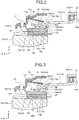
- the member 23 is movably provided in the axial direction between a position B1 (first position; FIG. 2 ) at which torque is transmitted by friction among the members 10 and 12 and a position B2 (second position; FIG. 5 ) at which no torque is transmitted between the members 10 and 12.
- the rotation transmitting unit 2 is placed in the transmitting state when the member 23 comes at the position B1, and in the disconnected state when the member 23 comes at the position B2.
- the member 23 is coupled with an actuator through an operation member (not illustrated).
- the member 23 receives an operating force (drive power) of the actuator and moves in the axial direction.
- the member 23 and the operation member are transmitted to the member 23 and the operation member through the member 14 and the bearing 22.
- the member 23 may be moved by an operation on a clutch pedal by an operator (driver) instead of the actuator.
- the member 23 and the bearing 22 are an exemplary third member.
- the elastic member 15 is provided between the member 11 and the member 14.
- the elastic member 15 is rotatably provided about the rotation center Ax.
- the elastic member 15 rotates integrally with members 11 and 14.
- the elastic member 15 is formed as a ring-like plate about the rotation center Ax.
- the elastic member 15 is, for example, a disc spring (cone spring).
- the elastic member 15 is supported by the protrusion 11c of the member 11 and the protrusion 14f of the member 14.
- the protrusion 11c is positioned more radially outside than the protrusion 14f.
- the part of the elastic member 15 supported by the protrusion 11c is positioned more radially outside than the part of the elastic member 15 supported by the protrusion 14f.
- the elastic member 15 elastically deforms in accordance with an axial distance between the member 11 (the protrusion 11c) and the member 14 (the protrusion 14f). Specifically, as illustrated in FIGS. 2, 3 , 4, and 5 , as the member 14 approaches the other axial side, the elastic member 15 deforms in a further bent posture (shape) toward the other axial side at a further radial inner position with the protrusion 11c as a pivot. In the present embodiment, the further on the other axial side the member 14 is, the larger the elastic deformation of the elastic member 15 in the axial direction is and the smaller the force (elastic force or reaction force) applied from the elastic member 15 to the members 11 and 14 is.
- the elastic member 15 is an exemplary first elastic member.
- the elastic member 16 is provided between the member 13 (member 12) and the member 14. Only one elastic member 16 is provided.
- the elastic member 16 is rotatably provided about the rotation center Ax.
- the elastic member 16 rotates integrally with the members 13 and 14.
- the elastic member 16 is formed as a ring-like plate about the rotation center Ax.
- the elastic member 16 is, for example, a disc spring (cone spring).
- the elastic member 16 includes faces 16a and 16b.
- the face 16a is on one axial side of the elastic member 16.
- the face 16a opposes the face 13c of the member 13.
- the face 16b is on the other axial side of the elastic member 16.
- the face 16b opposes the face 14c.
- the elastic member 16 elastically deforms in accordance with an axial distance between the member 13 and the member 14 (the protrusion 14e). Specifically, as illustrated in FIGS. 5, 4 , 3, and 2 , along with the motion of the member 14 to the one axial side, the elastic member 16 deforms in a posture (shape) directing further to the one axial side at a further radial inner position. In the present embodiment, the further on the one axial side the member 14 is, the larger the elastic deformation of the elastic member 16 in the axial direction is and the larger the force (elastic force or reaction force) applied to the members 13 and 14 is.
- the elastic member 16 is an exemplary second elastic member.
- the posture C1 is an exemplary first posture.
- FIG. 4 illustrates the state that the members 10 and 12 and the frictional members 12e and 12f are in contact with each other, and the member 14 and the elastic member 16 are in contact with each other.
- FIG. 4 illustrates a boundary state between the disconnected state and the slipping state, which may be referred to as a disconnection starting state since it corresponds to a stroke position of the member 23 at which the clutch starts disconnected.
- the elastic member 16 is in the posture C3.
- the posture C3 is an exemplary second posture.
- FIG. 5 shows the state in which the clutch is completely disconnected at the stroke of the member 23, and thus may be referred to as a disconnection completed state.
- the elastic member 16 is in the posture C4.
- the protrusion 13e supports the elastic member 16 in the axial direction, but the protrusion 13f does not support the elastic member 16.
- the protrusions 13e and 13f both support the elastic member 16 in the axial direction.
- the protrusion 13f supports the elastic member 16 in the axial direction.
- the protrusion 13e axially supports the elastic member 16 in the postures C2 to C4 but does not support the elastic member 16 in the posture C1.
- the protrusion 13f axially supports the elastic member 16 in the postures C1 and C2 but does not support the elastic member 16 in the postures C3 and C4.
- a position B4 of the member 23 in the state illustrated in FIG. 3 is the position (boundary) at which the state of the elastic member 16 supported by the member 13 changes.
- the member 13 supports the elastic member 16 through the protrusion 13f when the member 23 comes closer to the position B1 than the position B4, and supports the elastic member 16 through the protrusion 13e when the member 23 comes closer to the position B2 than the position B4.
- the elastic member 16 is more easily bendable (deform, deflect, or have a lower stiffness) than in the state illustrated in FIG. 2 , in accordance with the axial force from the member 14.
- the amount of change in the elastic force of the elastic member 16 in response to the amount of change (amount of movement) in the axial position of the member 14 is smaller than in the state illustrated in FIG. 2 . That is, in the state illustrated in FIG. 2 , the amount of change in the elastic force of the elastic member 16 in response to the amount of change (amount of movement) in the axial position of the member 14 is larger than in the states illustrated in FIGS. 5 and 4 .
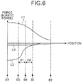
- FIG. 6 illustrates the magnitude of force (elastic force or axial components) acting on the member 14 from each of the elastic members 15, 16, and 20 corresponding to the positions of the member 23.
- line L1 represents the force of the elastic member 15 applied to the member 14
- line L2 represents the force of the elastic member 16 applied to the member 14
- line L3 represents the force of the elastic member 20 applied to the member 14.
- the vertical axis represents the force (elastic force) acting on the member 14
- the horizontal axis represents the axial position of the member 23.
- the origin of the horizontal axis in FIG. 6 represents the position B1 of the member 23 ( FIGS.
- the positive (upper) side of the vertical axis in FIG. 6 corresponds to the direction (one axial side) in which the member 14 approaches the member 10, and the negative (lower) side corresponds to the direction (the other axial side) in which the member 14 moves away from the member 10.
- the elastic member 15 corresponding to line L1 in FIG. 6 elastically deforms in the axial direction in accordance with a change in the axial position of the member 23 and applies force to the members 13, 14, and 23 to move closer to the member 12 (the members 13 and 14 are pressed toward the members 10 and 12).
- the magnitude (absolute value) of the force of the elastic member 15 is at maximum when the member 23 is located at the position B1 (origin), and gradually decreases as the member 23 moves from the position B1 to the position B2 in the axial direction.
- the elastic member 16 corresponding to line L2 in FIG. 6 applies force to the members 14 and 23 to move away from the member 12 (force opposite to the pressing force to the member 13 toward the members 10 and 12).
- the elastic member 16 elastically deforms in the axial direction in accordance with a change in the axial position of the member 23 and generates elastic force against elastic force of the elastic member 15 applied to the member 23 while the member 23 moves from the position B1 to the position B2.
- the magnitude (absolute value) of the force of the elastic member 16 is at maximum when the member 23 is located at the position B1 (origin), and gradually decreases as the member 23 moves from the position B1 to the position B2 in the axial direction.
- the magnitude of force of the elastic member 16 applied to the members 13, 14, and 23 is smaller than the magnitude of force of the elastic member 15 applied to the members 13, 14, and 23.
- the elastic member 16 also applies force to the members 13, 14, and 23 when the member 23 is located between the position B1 and a position B3 in the disconnection starting state.
- a load is generated from the load of the elastic member 20, and the elastic member 16 thus applies force to the members 13, 14, and 23.
- the elastic member 20 applies force to the members 13, 14, and 23 to move away from the member 12 (force opposite to the pressing force to the members 13 and 14 toward the members 10 and 12).
- the magnitude (absolute value) of the force of the elastic member 20 is constant when the member 23 is located between the position B1 and the position B3, and gradually decreases as the member 23 moves from the position B3 toward the other axial side.
- the elastic member 20 generates elastic force against the force of the elastic member 15 applied to the member 23 in the disconnected state in which no torque is transmitted between the member 10 and the member 23.
- the elastic force of the elastic member 20 is used to, for example, separate the member 13 and the frictional member 12f from each other in the disconnected state (disconnection completed state) illustrated in FIG. 5 .
- the rotation transmitting unit 2 of the clutch device 1 is placed in the transmitting state, and the member 12 is sandwiched between the members 10 and 13 due to the force from the elastic member 16.
- the member 23 is applied with the force (operation force) of the actuator to move toward the other axial side (right side in FIG. 1 ) against the force of the elastic member 15, thereby placing the rotation transmitting unit 2 in the slipping state, the disconnection starting state, and the disconnection completed state.
- the elastic member 16 and the elastic member 20 generate force to reduce the force generated by the elastic member 15.
- the elastic member 16 and the elastic member 20 contribute to reducing the operating force for the member 23 so as to transition the rotation transmitting unit 2 from the transmitting state to the slipping state, the disconnection starting state, or the disconnection completed state.
- the elastic members 15, 16, and 20 are set to allow torque to be transmitted between the members 10 and 12 without slipping while the member 23 is located at the position B1.
- the elastic members 15, 16, and 20 are also set so that the force of the elastic member 15 is reduced by the force of the elastic members 16 and 20 to reduce the operating force for the member 23 to a relatively small force. It should be understood from FIG. 6 that the elastic members 16 and 20 generate reverse force to the force of the elastic member 15.
- the elastic member 16 is an exemplary assist spring.
- the amount of change in the elastic force of the elastic member 16 (elastic force change rate, the gradient of line L2 in FIG. 6 ) relative to the amount of change (displacement per unit length) in the axial position of the member 23 varies in accordance with the state (position) of the elastic member 16 supported by the member 13.
- the amount of change in the elastic force of the elastic member 16 relative to the amount of axial change of the member 23 is different between a movement interval D1 and a movement interval D2 of the member 23.
- the movement interval D1 is an interval between the position B5 of the member 23 between the position B1 and the position B4, and the position B4.
- a length (distance) between the position B4 and the position B5 is equal to a length (distance) between the position B3 and the position B4.
- the elastic member 16 takes the posture C1.
- the movement interval D2 is closer to the position B2 than the movement interval D1.
- the movement interval D2 is an interval between the position B3 and the position B4.
- the elastic member 16 takes the posture C3.
- the amount of change in the elastic force of the elastic member 16 relative to the amount of change in the axial position of the member 23 in the movement interval D1 is larger than that in the movement interval D2.
- the movement interval D1 is an exemplary first movement interval
- the movement interval D2 is an exemplary second movement interval.
- the clutch device 1 includes one elastic member 16 as the second elastic member.
- the clutch device 1 can have a simpler configuration than the one including multiple second elastic members. It is easier to reduce a space in the member 11.
- a clutch operation load may largely vary and increase because of accumulation of variation in the elastic force of the second elastic members or loss due to sliding or settling.
- the present embodiment employs only one elastic member 16, making it possible to reduce the variation in the clutch operation load and prevent it from increasing.
- the member 13 includes the protrusion 13e and the protrusion 13f.
- the protrusion 13f supports the elastic member 16 in the axial direction when the elastic member 16 is in the elastically deformed posture C1, and does not support the elastic member 16 when the elastic member 16 is in the elastically deformed posture C3.
- the protrusion 13e axially supports the elastic member 16 in the posture C3.
- the supporting part (support state or position) of the member 13 for the elastic member 16 is changed depending on a change in the posture of the elastic member 16 following the motion of the member 23. By this change of the supporting part, the amount of change in the elastic force of the elastic member 16 relative to the amount of change in the position of the member 23 varies.
- the present embodiment can attain a relatively simple configuration that obtains such a characteristic that the amount of change in the elastic force of the elastic member 16 relative to the amount of change in the position of the member 23 varies in accordance with the position of the member 23.
- the protrusion 13e and the protrusion 13f are disposed in the member 13 but may be disposed in the member 14.
- the elastic member 16 takes the posture C1 in the movement interval D1 of the member 23 and the posture C3 in the movement interval D2 of the member 23.
- the amount of change in the elastic force of the elastic member 16 relative to the amount of change in the axial position of the member 23 in the movement interval D1 of the member 23 is larger than that in the movement interval D2 of the member 23.
- the amount of change in the elastic force of the elastic member 16 relative to the amount of change in the axial position of the member 23 is smaller in the movement interval D2 in which the members 10 and 12 are in the slipping state (half-clutch state) near the disconnected state than in the movement interval D1 in which the members 10 and 12 are in the transmitting state. This further reduces the change in the operation force for axially moving the member 23 in the slipping state, which facilitates half-clutch (middle-torque) control.
- the member 13 is provided between the member 23 and the member 12 to be rotatable about the rotation center Ax and movable in the axial direction.
- the elastic member 16 is positioned on the opposite side of the member 13 from the member 12 in the axial direction.
- the member 14 includes the protrusion 14f to contact with the elastic member 15 and the protrusion 14e to contact with the elastic member 16, and is provided between the elastic member 15 and the elastic member 16.
- the member 14 moves in the axial direction along with the axial motion of the member 23.
- the elastic member 16 is provided between the member 14 and the member 12.
- the member 14 can be used as the transmission paths of force from the member 23 to the member 12, the elastic force of the elastic member 15, and the elastic force of the elastic member 16.
- the structure including the member 23, the elastic member 15, and the elastic member 16 can be relatively simplified.
- the elastic member 16 is a disc spring of a circular shape about the rotation center Ax.
- the elastic member 16 can be relatively simplified in structure.
- the protrusion 13f has a circular shape about the rotation center Ax.
- the elastic member 16 can be supported more stably.
- the clutch device 1 includes the elastic member 20 different from the elastic member 16.
- the elastic member 20 generates elastic force against the force of the elastic member 15 to the member 23 in the disconnected state in which no torque is transmitted between the member 10 and the member 23.
- the member 23 can be applied with the elastic force against the force of the elastic member 15.
- a clutch device 1A according to the present embodiment illustrated in FIGS. 7 to 10 differs from that in the first embodiment in the member 13 and the elastic member 16, for example.
- the protrusion 13f is provided on the face 13c of the member 13 without the protrusion 13e (refer to FIG. 1 ).
- the protrusion 13d is also provided on the face 13c.
- the protrusion 13d protrudes toward the elastic member 16 (the other axial side).
- the protrusion 13f is provided more radially inside than the protrusion 13d.
- the elastic member 16 includes a disc spring 16g and a plate spring 16h.
- the disc spring 16g has a ring-like shape about the rotation center Ax.
- the plate spring 16h is provided more radially outside than the disc spring 16g.
- the plate spring 16h includes plates 16i and 16j and a contact 16k.
- the plate 16i extends outward in the radial direction from a radial outer end of the disc spring 16g.
- the plate 16j extends in the circumferential direction from a radial outer end of the plate 16i with a spacing from the disc spring 16g.
- the contact 16k is provided on the opposite side of the plate 16j from the plate 16i. The contact 16k contacts with the protrusion 13d of the member 13.
- the action point 16c is on the radial inner part of the disc spring 16g.
- the plate 16i may extend inward in the radial direction from a radial inner end of the disc spring 16g, and the plate 16j may extend in the circumferential direction from a radial inner end of the plate 16i with a spacing from the disc spring 16g.
- the plate 16i is an exemplary first plate
- the plate 16j is an exemplary second plate.
- the protrusion 14e of the member 14 is in contact with the action point 16c of the disc spring 16g.
- the protrusion 13f is positioned on one axial side of the disc spring 16g. While the disc spring 16g is positioned on the other axial side (second posture; not illustrated), the protrusion 13f is separated from the elastic member 16.
- the elastic member 16 elastically deforms and the disc spring 16g moves from the other axial side to the one axial side, as illustrated in FIG. 9 to contact the protrusion 13f at the radial outer end (the first posture).
- the plate spring 16h of the elastic member 16 mainly deforms. While the disc spring 16g is in contact with the protrusion 13f (the first posture), the disc spring 16h of the elastic member 16 mainly deforms.
- the protrusion 13f is an exemplary first support
- the protrusion 13d is an exemplary second support.
- the member 13 includes the protrusion 13d and the protrusion 13f.
- the protrusion 13f axially supports the elastic member 16 elastically deformed in the first posture, and does not support the elastic member 16 elastically deformed in the second posture.
- the protrusion 13d axially supports the elastic member 16 in the first posture and the second posture.
- the supporting part (the state or position of support) of the member 13 for the elastic member 16 is changed depending on a change in the posture of the elastic member 16 along with the motion of the member 23. By the change of the supporting part, the amount of change in the elastic force of the elastic member 16 relative to the amount of change in the position of the member 23 varies.
- the present embodiment achieves a relatively simple configuration that obtains such a characteristic that the amount of change in the elastic force of the elastic member 16 relative to the amount of change in the position of the member 23 varies in accordance with the position of the member 23.
- the elastic member 16 includes the disc spring 16g and the plate spring 16h.
- the bending stiffness (elastic force) of the elastic member 16 can be adjusted by adjusting the specifications (for example, length, thickness, width, or shape) of the plate spring 16h.
- the degree of freedom for setting the bending stiffness (elastic force) of the elastic member 16 is higher than that for the elastic member 16 formed of only the disc spring 16g.
- the plate spring 16h includes the plate 16i extending from the disc spring 16g in the radial direction (outward or inward), and the plate 16j extending from the plate 16i in the circumferential direction.
- the plate spring 16h has a reduced radial length than the plate spring 16h extending in the radial direction.
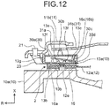
- a clutch device 1B according to the present embodiment illustrated in FIGS. 11 and 12 is different from that in the first embodiment in including a member 30 and an elastic member 31.
- the clutch device 1B does not include the elastic member 15.
- the member 11 includes the wall part 11b but does not include the wall 11a (refer to FIG. 1 ).
- the member 30 is positioned on the other axial side of the elastic member 16.
- the elastic member 31 is positioned on the other axial side of the member 30.
- the member 30 is provided between the elastic member 16 and the elastic member 31.
- the member 30 includes a wall 30a.
- the wall 30a is formed as a ring-like plate about the rotation center Ax.
- the wall 30a expands in the direction intersecting with (substantially orthogonal to) the rotation center Ax.
- the wall 30a is provided with protrusions 30b and 30c.
- the protrusion 30b is provided on the other axial-side face of the wall 30a.
- the protrusion 30b is provided between a radial outer end and a radial inner end of the wall 30a.
- the protrusion 30b faces the elastic member 31.
- the protrusion 30b contacts with the elastic member 31 (a disc spring 31a thereof).
- the protrusion 30c is provided on one axial side of the wall 30a.
- the protrusion 30c is provided more radially inside than the protrusion 30b.
- the protrusion 30c faces the elastic member 16.
- the protrusion 30c contacts with the elastic member 16 (the action point 16c thereof).
- the wall 30a is provided with a guide 30d (support).
- the guide 30d extends toward the one axial side from a radial inner end of the wall 30a.
- the guide 30d is positioned radially inside the circular elastic member 16.
- the guide 30d is provided in a predetermined area (part) about the rotation center Ax.
- the guide 30d moves in the radial direction, contacts the elastic member 16, and radially supports it.
- the guide 30d may have a circular shape about the rotation center Ax.
- the radial outer end of the wall 30a is coupled with a support 13g.
- the support 13g is provided at the radial outer end of the member 13.
- the support 13g has a cylindrical shape about the rotation center Ax.
- the support 13g protrudes toward the other axial side.
- the wall 30a and the support 13g may be coupled with each other through a spline structure. In other words, the member 30 integrally rotates with the member 13 and is movably supported in the axial direction by the member 13.
- the elastic member 31 is provided between the bearing 22 and the member 30.
- the elastic member 31 is a diaphragm spring.
- the elastic member 31 includes the disc spring 31a and a plurality of levers 31b.
- the disc spring 31a is provided on the radial outer part of the elastic member 31.
- the disc spring 31a is formed as a ring-like plate about the rotation center Ax.
- the disc spring 31a expands in a direction intersecting with the rotation center Ax.
- Each lever 31b extends radially inward from a radial inner end of the disc spring 31a.
- the levers 31b are aligned in the circumferential direction of the disc spring 31a.
- Each lever 31b is a triangular plate sharply angled radially inward.
- the lever 31b expands in the direction intersecting with the rotation center Ax. Part of the lever 31b between the radial outer end and the radial inner end is swingably supported by the wall 11b.
- the elastic member 31 and the wall 11b are coupled with each other through a support member 32 (for example, a wire rod).
- the elastic member 31 elastically deforms in the axial direction along with the axial motion of the member 23.
- the elastic member 31 elastically deforms to apply force (elastic force) to the member 30 and the bearing 22.
- the elastic member 31 applies force to the member 30 to move the member 30 closer to the wall 13a, and applies force to the bearing 22 to move away from the member 30.
- the force of the elastic member 31 applied to the member 30 is transmitted to the member 12 through the elastic member 16 and the member 13.
- the force of the elastic member 31 applied to the bearing 22 is transmitted to the member 23 through the bearing 22.
- the elastic member 31 is an exemplary first elastic member.
- the bearing 22 is positioned on the other axial side of the elastic member 31.
- An outer end of the bearing 22 is in contact with a radial inner end of the lever 31b.
- the radial outer end of the bearing 22 presses the radial inner end of the lever 31b toward the one axial side.
- a radial inner end of the bearing 22 is supported by the member 23.
- the member 23 covers the protrusion 101 from the radial outer periphery.
- the member 23 is movably supported in the axial direction by the protrusion 101.
- the member 23 receives the operation force (drive power) of the actuator (not illustrated) and moves in the axial direction.
- the bearing 22 and the member 23 integrally move in the axial direction.
- the actuator moves the lever 31b and the disc spring 31a through the member 23 and the bearing 22, and thus moves the member 30 in the axial direction.
- the elastic force of the elastic member 31 pressing the member 30 toward the one axial side is at maximum, placing the rotation transmitting unit 2 in the transmitting state.
- the members 12 and 13 are separated by the elastic member 20, placing the rotation transmitting unit 2 in the disconnection completed state (disconnected state).
- the positions of the member 23 when the rotation transmitting unit 2 is in the transmitting state and in the disconnection completed state (disconnected state) are reverse to those in the first embodiment.
- the elastic member 31 elastically deforms in accordance with the axial position of the member 23.
- the elastic force of the elastic member 31 has the same characteristic as that of the elastic member 15 in the first embodiment.
- the posture of the elastic member 16 changes as the member 23 moves in the axial direction.
- the posture of the elastic member 16 changes in the order of the posture C1, the posture C2, the posture C3, and the posture C4.
- the posture of the elastic member 16 changes in the order of the posture C1, the posture C2, the posture C3, and the posture C4.
- the member 13 includes the protrusion 13e and the protrusion 13f.
- the supporting part the state or position of support
- the amount of change in the elastic force of the elastic member 16 in response to the amount of change in the position of the member 23 varies.
- the present embodiment achieves a relatively simple configuration that obtains such a characteristic that the amount of change in the elastic force of the elastic member 16 in response to the amount of change in the position of the member 23 varies in accordance with the position of the member 23.
- a clutch device 1C according to the present embodiment illustrated in FIGS. 13 and 14 differs from that in the second embodiment in the protrusion 13d and the protrusion 13f of the member 13, and the plate spring 16h of the elastic member 16.
- the protrusion 13d and the protrusion 13f are provided on the face 13c of the member 13. In the present embodiment, however, the protrusion 13f is provided more radially outside than the protrusion 13d.
- the elastic member 16 includes the disc spring 16g and the plate spring 16h.
- the plate spring 16h is provided more radially inside than the disc spring 16g.
- the plate spring 16h includes the plate 16i and the contact 16k but is not provided with the plate 16j ( FIG. 8 ).
- the plate 16i extends radially inward from the radial inner end of the disc spring 16g.
- the contact 16k is provided on the opposite side of the plate 16i from the disc spring 16g.
- the contact 16k is in contact with the protrusion 13d of the member 13.
- the action point 16c is on a radial outer part of the disc spring 16g.
- the protrusion 14e of the member 14 is in contact with the action point 16c of the disc spring 16g.
- the protrusion 13f is positioned on the one axial side of the disc spring 16g. While the disc spring 16g is positioned on the other axial side (the second posture; not illustrated), the protrusion 13f is separated from the elastic member 16.
- the elastic member 16 elastically deforms, and the disc spring 16g moves from the other side to the one side in the axial direction and contacts the protrusion 13f at the radial inner end (the first posture) as illustrated in FIG. 14 .
- the disc spring 16g moves from the position on the other axial side and contacts with the protrusion 13f, in other words, while (the second posture) the disc spring 16g is separated from the protrusion 13f, the plate spring 16h deforms in the elastic member 16. While (the first posture) the disc spring 16g is in contact with the protrusion 13f, the disc spring 16g mainly deforms in the elastic member 16.
- the wall 13a is provided with a guide 13h (support).
- the guide 13h extends from the face 13c toward the other axial side.
- the guide 13h is positioned radially inside the circular disc spring 16g of the elastic member 16.
- the guide 13h is provided in a predetermined area (part) about the rotation center Ax. The guide 13h radially moves to contact and support the elastic member 16.
- the member 13 includes the protrusion 13d and the protrusion 13f.
- the protrusion 13f axially supports the elastic member 16 elastically deformed in the first posture, but does not support the elastic member 16 elastically deformed in the second posture.
- the protrusion 13d axially supports the elastic member 16 in the first posture and the second posture.
- the supporting part (the state or position of support) of the member 13 for the elastic member 16 is changed in accordance with a change in the posture of the elastic member 16 as the member 23 moves.
- the supporting part the amount of change in the elastic force of the elastic member 16 relative to the amount of change in the position of the member 23 varies.
- the present embodiment achieves a relatively simple configuration that obtains such a characteristic that the amount of change in the elastic force of the elastic member 16 in response to the amount of change in the position of the member 23 varies in accordance with the position of the member 23.
- the elastic member 16 includes the disc spring 16g and the plate spring 16h.
- the bending stiffness (elastic force) of the elastic member 16 can be adjusted by adjusting the specifications (for example, length, thickness, width, or shape) of the plate spring 16h.
- the degree of freedom for setting the bending stiffness (elastic force) of the elastic member 16 is higher than that for the elastic member 16 formed of only the disc spring 16g.
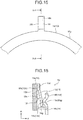
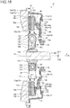
- a clutch device 1D according to the present embodiment illustrated in FIGS. 15 and 16 differs from the one in the fourth embodiment in the protrusion 13d and the protrusion 13f of the member 13, and the plate spring 16h of the elastic member 16.
- the protrusion 13d and the protrusion 13f are provided on the face 13c of the member 13. In the present embodiment, however, the protrusion 13f is provided radially more inside than the protrusion 13d.
- the elastic member 16 includes the disc spring 16g and the plate spring 16h.
- the plate spring 16h is provided more radially outside than the disc spring 16g.
- the plate 16i of the plate spring 16h extends radially outward from the radial outer end of the disc spring 16g.
- the contact 16k is provided on the opposite side of the plate 16i from the disc spring 16g. The contact 16k contacts with the protrusion 13d of the member 13.
- the action point 16c is on a radial inner part of the disc spring 16g.
- the protrusion 14e of the member 14 is in contact with the action point 16c of the disc spring 16g.
- the protrusion 13f is positioned on the one axial side of the disc spring 16g. While the disc spring 16g is positioned on the other axial side (the second posture; FIG. 16 ), the protrusion 13f is separated from the elastic member 16.
- the elastic member 16 elastically deforms and the disc spring 16g moves from the other side to the one side in the axial direction to contact the protrusion 13f at the radial outer end (the first posture; not illustrated). While the disc spring 16g moves from the position on the other axial side to contact with the protrusion 13f, in other words, while (the second posture; FIG.
- the disc spring 16g is separated from the protrusion 13f, the plate spring 16h of the elastic member 16 mainly deforms. While (the first posture) the disc spring 16g is in contact with the protrusion 13f, the disc spring 16g of the elastic member 16 mainly deforms.
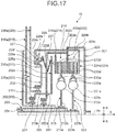
- a clutch device 1E according to the present embodiment illustrated in FIG. 17 is a so-called twin clutch including two rotation transmitting units 210 and 220.
- the movable units (members 214, 224, 215,225, 216, and 226, and bearings 231 and 232, for example) are moved in the axial direction by the not-illustrated actuator, switchably placing the rotation transmitting units 210, 220 in a state that rotation (torque) is transmitted selectively through one of the rotation transmitting unit 210 and the rotation transmitting unit 220, and a state that the rotation transmission through both of the rotation transmitting unit 210 and the rotation transmitting unit 220 is interrupted.
- the rotation transmitting unit 210 can change the rotation transmitting state among members 201 and 202 and a shaft 203.
- the rotation transmitting unit 220 can change the rotation transmitting state among the members 201 and 202 and a shaft 204.
- the rotation transmitting units 210 and 220 can transmit rotation in a so-called half-clutch state in which output torque is smaller than input torque.
- the clutch device 1E includes the members 201 and 202, members 213 to 216, the shaft 203, and the bearing 231 as components involving in the rotation transmission and disconnection through the rotation transmitting unit 210.
- the members 201, 202, and 213 to 216 and the shaft 203 may be made from, for example, a metal material.
- the shafts 203 and 204 are rotatably supported by a case 205 (for example, a transmission case) through a bearing (not illustrated).
- the shafts 203 and 204 rotate about the rotation center Ax.
- the shafts 203 and 204 are multiple (in the present embodiment, two) concentric rotational elements.
- One of the shafts 203 and 204 at least partially have a tubular shape, whereas the other is placed in the tubular shaft.
- the case 205 is provided (fixed or coupled) with a protrusion 251.
- the protrusion 251 covers the shafts 203 and 204 from radially outside (outer periphery).
- the protrusion 251 protrudes as a tube (cylinder) from a wall 252 toward the other axial side (right side in FIG. 17 ).
- the protrusion 251 may be formed integrally with any other part (for example, the wall 252) of the case 205, or may be formed as a member separate from the other part and integrated with the other part with a coupling member (for example, a screw or a rivet; not illustrated).
- the case 205 is an exemplary housing.
- the member 201 (for example, a drive plate or a flywheel) is rotatably provided about the rotation center Ax.
- the member 201 includes walls 201a and 201b.
- the wall 201a is formed as a disk and expands in a direction intersecting with (substantially orthogonal to) the rotation center Ax.
- the wall 201b protrudes toward the one axial side (left side in FIG. 17 ) from an end of the wall 201a, and has a cylindrical shape.
- the member 201 is supported by a drive source (not illustrated; for example, an engine).
- the member 202 (for example, a clutch cover) is rotatably provided about the rotation center Ax.
- the member 202 includes walls 202a, 202b, and 202c.
- the wall 202a is connected (coupled or fixed) with the wall 201b of the member 201.
- the wall 202a is formed as a ring-like plate and expands in the direction intersecting with (substantially orthogonal to) the rotation center Ax.
- the wall 202b protrudes toward the one axial side (left side in FIG. 17 ) from an radial outer end of the wall 202a, and has a cylindrical shape.
- the wall 202c is connected (coupled or fixed) with the wall 202b.
- the wall 202c has a disk-like shape and expands in the direction intersecting with the rotation center Ax.
- One of rotational parts (for example, a rotational part radially inside) of a bearing 233 is connected (coupled or fixed) with the protrusion 251, whereas the other rotational part (for example, a rotational part radially outside) is connected (coupled or fixed) with a radial inner end of the wall 202c (the member 202).
- the wall 202c (member 202) is rotatably supported about the rotation center Ax by the bearing 233.
- the member 202 is an exemplary first member.
- the member 213 (for example, a first clutch disc) is provided on the one axial side (left side in FIG. 17 ) of the wall 202a.
- the member 213 includes walls 213a and 213b, an elastic member 213c, a frictional member 213d, and a spline coupling 213e.
- the wall 213a has a disk-like shape and expands in the direction intersecting with (substantially orthogonal to) the rotation center Ax.
- the wall 213b has a disk-like shape and expands in the direction intersecting with (substantially orthogonal to) the rotation center Ax.
- one of the wall 213a and the wall 213b (in the present embodiment, for example, the wall 213b) is sandwiched in the axial direction between the two other walls (in the present embodiment, for example, the walls 213a).
- the walls 213a and 213b can rotate with an angular difference (mutually shifted) in at least part of their rotational ranges.
- the elastic member 213c (for example, a coil spring) is sandwiched between the wall 213a and the wall 213b to be able to elastically expand and contract substantially in the circumferential direction.
- the elastic member 213c expands and contracts in the circumferential direction in accordance with the relative rotation angle between the wall 213a and the wall 213b.
- the elastic member 213c elastically contracts to store torque as compression force and elastically expands to release compression force as torque. In other words, the member 213 can reduce variation in torque through the elastic member 213c.
- the member 213 rotates integrally with the shaft 203.
- the member 213 is movably provided in the axial direction. Specifically, one of the wall 213a and the wall 213b (in the example in FIG. 17 , the wall 213b) is supported by the shaft 203 through the cylindrical spline coupling 213e.
- the other of the wall 213a and the wall 213b (in the example in FIG. 17 , the wall 213a) is positioned between the walls 202a and 214a and includes a region sandwiched between the walls 202a and 214a.
- Frictional members 213d are provided on both axial sides of the sandwiched region of the other wall (the wall 213a).
- the member 213 is provided to be switchably placed at least in the transmitting state in which the member 213 is pressed against the wall 202a of the member 202 in the axial direction of the rotation center Ax to generate friction and transmit torque between the member 213 and the member 202 by the friction, and in the disconnected state in which no torque is transmitted between the member 213 and the member 202.
- the member 214 (for example, a first pressure plate) includes the wall 214a.
- the wall 214a is formed as a ring-like plate and expands in the direction intersecting with (substantially orthogonal to) the rotation center Ax.
- the member 214 is movably supported by the member 202 in the axial direction.
- the member 214 is configured to rotate integrally with the member 202.
- the member 214 can move in the axial direction between a transmitting position (not illustrated) and a disconnected position ( FIG. 17 ).
- the wall 213a is sandwiched between the wall 202a and the wall 214a through the frictional members 213d.
- rotation is transmitted between the wall 202a and the wall 213a (the transmitting state).
- the wall 213a is further separated from both of the wall 202a and the wall 214a than at the transmitting position.
- the rotation transmission between the wall 202a and the wall 214a is interrupted (the disconnected state).
- the frictional members 213d are provided between the wall 202a and the wall 213a and between the wall 213a and the wall 214a. Slipping occurs between the frictional members 213d and the walls 202a and 214a depending on the position of the wall 214a (so-called half-clutch state). Frictional members may also be provided on the walls 202a and 214a.
- the member 215 (for example, a first release plate) includes a wall 215a, penetrators 215b, and a connection 215c.
- the wall 215a has a disk-like shape and expands in the direction intersecting with (substantially orthogonal to) the rotation center Ax.
- the penetrators 215b are connected (coupled or fixed) with the wall 215a and axially penetrate through openings 202d in the wall 202c of the member 202.
- the connection 215c has a ring-like shape and is connected (coupled or fixed) with the penetrators 215b.
- the member 215 is rotatably supported by the protrusion 251 about the rotation center Ax through the bearing 231.
- One of rotational parts (for example, a rotational part radially inside) of the bearing 231 is configured not to rotate relative to the protrusion 251, and is movably supported in the axial direction by the protrusion 251.
- the other rotational part (for example, a rotational part radially outside) of the bearing 231 is connected (coupled or fixed) with the connection 215c.
- the member 215 is supported to be movable in the axial direction and rotatable about the rotation center Ax by the protrusion 251 through the bearing 231.
- the member 215 rotates integrally with the member 202 through circumferential drag or friction between the members 202 and 215.
- An elastic member 217 (for example, a disc spring or a diaphragm spring) is provided between the member 202 (the wall 202c thereof) and the member 215 (the wall 215a thereof).
- the elastic member 217 can apply axial force (load) to the member 202 and the member 215.
- the elastic member 217 can provide direct or indirect pressing force to the member 214 and the member 216.
- the member 216 is movably provided relative to the case 205 in the axial direction.
- the member 216 includes an extension 216a (arm, lever, or wall).
- the extension 216a extends in the radial direction and has a plate-like and band-like, or a rod-like shape.
- the extension 216a is connected (coupled or fixed) with a rotational part of the bearing 231 supported by the protrusion 251 (for example, a rotational part radially inside).
- the actuator (not illustrated) moves the member 216 in the axial direction, thereby moving the member 215 and the member 214 in the axial direction and switching the state of the rotation transmitting unit 210 among the transmitting state, the half-clutch state, and the disconnected state.
- the clutch device 1E includes the members 201 and 202, members 223 to 226, the shaft 204, and the bearing 232 as components involving in the rotation transmission and disconnection by the rotation transmitting unit 220.
- the members 223 to 226 and the shaft 204 may be all made from, for example, a metal material.
- the member 223 (for example, a second clutch disc) is positioned on the opposite side of the member 213 (the other axial side; right side in FIG. 17 ) from the wall 202a.
- the member 223 includes walls 223a and 223b, an elastic member 223c, a frictional member 223d, and a spline coupling 223e.
- the wall 223a has a disk-like shape and expands in the direction intersecting with (substantially orthogonal to) the rotation center Ax.
- the wall 223b has a disk-like shape and expands in the direction intersecting with (substantially orthogonal to) the rotation center Ax.
- one of the wall 223a and the wall 223b may be sandwiched between the two other walls in the axial direction.
- the walls 223a and 223b can rotate with an angular difference (mutually shifted) in at least part of their rotational ranges.
- the elastic member 223c (for example, a coil spring) is sandwiched between the wall 223a and the wall 223b to be able to elastically expand and contract in the circumferential direction.
- the elastic member 223c expands and contracts in the circumferential direction in accordance with the relative rotation angle between the wall 223a and the wall 223b.
- the elastic member 223c elastically contracts to store torque as compression force and elastically expands to release compression force as torque.
- the member 223 can reduce variation in torque through the elastic member 223c.
- the member 223 is rotatably provided about the rotation center Ax.
- the member 223 rotates integrally with the shaft 204.
- the member 223 is movably provided in the axial direction. Specifically, one of the wall 223a and the wall 223b (in the example in FIG. 17 , the wall 223b) is supported by the shaft 204 through the spline coupling 223e.
- the other of the wall 223a and the wall 223b (in the example in FIG. 17 , the wall 223a) is positioned between the walls 202a and 224a and includes a region sandwiched between the walls 202a and 224a.
- the frictional members 223d are provided on both axial sides of the sandwiched region of the other wall (the wall 223a).
- the member 223 is provided to be switchably placed at least in the transmitting state in which the member 223 is pressed against the wall 202a of the member 202 in the axial direction of the rotation center Ax to transmit torque between the member 223 and the member 202 through friction, and the disconnected state in which no torque is transmitted between the member 223 and the member 202.
- the member 224 (for example, the first pressure plate) is provided between the bearing 232 and the member 223.
- the member 224 is positioned outside the bearing 232 and the member 223.
- the member 224 is rotatably provided about the rotation center Ax and movable in the axial direction.
- the member 224 includes a wall 224a, penetrators 224b, and a wall 224c.
- the wall 224a is formed as a ring-like plate, and expands in the direction intersecting with (substantially orthogonal to) the rotation center Ax.
- the penetrators 224b are connected (coupled or fixed) with the wall 224a, and axially penetrate through openings 202e in the wall 202a of the member 202.
- the wall 224c has a ring-like shape and is connected (coupled or fixed) with the penetrator 224b.
- the member 224 is supported by the member 202 to be movable in the axial direction.
- the member 224 is configured to rotate integrally with the member 202.
- the member 224 is an exemplary fourth member.
- the wall 224c includes protrusions 224e and 224f.
- the protrusions 224e and 224f are provided on the other axial-side face of the wall 224c.
- the protrusions 224e and 224f each have a circular shape about the rotation center Ax.
- the protrusion 224f is positioned more radially inside than the protrusion 224e.
- the protrusions 224e and 224f are positioned between a radial outer end (edge) and a radial inner end (edge) of the wall 224c.
- the protrusions 224e and 224f protrude toward an elastic member 235 (the other axial side).
- the protrusion 224f is an exemplary first support
- the protrusion 224e is an exemplary second support.
- the member 224 can move in the axial direction between the transmitting position (not illustrated) and the disconnected position ( FIG. 17 ).
- the wall 223a is sandwiched between the wall 202a and the wall 224a through the frictional members 223d.
- rotation is transmitted between the wall 202a and the wall 223a (the transmitting state).
- the wall 223a is further separated from both of the wall 202a and the wall 224a than at the transmitting position.
- the rotation transmission between the wall 202a and the wall 224a is interrupted (the disconnected state).
- the frictional members 223d are provided between the wall 202a and the wall 223a and between the wall 223a and the wall 224a. Slipping occurs between the frictional members 223d and the walls 202a and 224a depending on the position of the wall 224a (so-called half-clutch state). Frictional members may also be provided on the walls 202a and 224a.
- the member 225 (for example, a second release plate) is provided between an elastic member 227 and the elastic member 235.
- the member 225 moves in the axial direction along with the axial motion of the bearing 232.
- the member 225 is an exemplary fifth member.
- the member 225 includes a wall 225a.
- the wall 225a is positioned on the opposite side of the wall 215a from the wall 202c of the member 202.
- the wall 225a has a disk-like shape and expands in the direction intersecting with (substantially orthogonal to) the rotation center Ax.
- the bearing 232 is connected (coupled or fixed) with the radial inner end of the wall 225a.
- the member 225 is rotatably supported about the rotation center Ax through the bearing 232 by the connection 215c of the member 215.
- One of rotational parts (for example, a rotational part radially inside) of the bearing 232 is configured not to rotate relative to the member 215 and movably supported by the member 215.
- the other rotational part (for example, a rotational part radially outside) of the bearing 232 is connected (coupled) with the wall 225a.
- the member 225 rotates integrally with the member 202 through circumferential drag or friction between the members 202 and 225.
- the member 225 is movably, rotatably supported by the member 215 through the bearing 232 in the axial direction.
- Protrusions 225e and 225f are provided on the radial outer side of the wall 225a.
- the protrusion 225f is positioned more radially outside than the protrusion 225e.
- the protrusion 225e is positioned more radially inside than the protrusion 224f.
- the protrusion 225e is provided on one axial-side face of the wall 225a and protrudes toward the one axial side.
- the protrusion 225e contacts with the elastic member 235.
- the protrusion 225f is provided on the other axial-side face of the wall 225a and protrudes toward the other axial side.
- the protrusion 225f contacts with the elastic member 227.
- the protrusion 225e is an exemplary second contact
- the protrusion 225f is an exemplary first contact
- the wall 225a is provided with a guide 225g (support).
- the guide 225g extends from the wall 225a toward the one axial side.
- the guide 225g is positioned radially inside the circular elastic member 235.
- the guide 225g is provided in a predetermined area (part) about the rotation center Ax.
- the guide 225g moves in the radial direction and contacts and supports the elastic member 235 in the radial direction.
- the guide 225g may has a circular shape about the rotation center Ax.
- the elastic member 227 (for example, disc spring, diaphragm spring) is provided between the member 202 (the wall 202c thereof) and the member 225 (the wall 225a thereof).
- the elastic member 227 can apply axial force (load) to the member 202 and the member 225.
- the elastic member 227 can provide direct or indirect pressing force to the member 224 and the member 226.
- the elastic member 227 elastically deforms in the axial direction in accordance with a change in the axial position of the bearing 232, and generates elastic force to press the member 202 and the member 223 against each other.
- the elastic member 227 is an exemplary first elastic member.
- the elastic member 235 (for example, a disc spring) is provided between the member 225 (the wall 225a thereof) and the member 224 (the wall 224c thereof).
- the elastic member 235 is positioned on the same side of the member 224 as the member 223.
- the elastic member 235 is positioned outside the member 225 and the member 223.
- the elastic member 235 can apply axial force (load) to the member 225 and the member 224.
- the elastic member 235 can provide direct or indirect pressing force to the member 224 and the member 226.
- the elastic member 235 elastically deforms in the axial direction in accordance with a change in the axial position of the bearing 232 (third member), and generates elastic force against the force of the elastic member 227 applied to the bearing 232 when the bearing 232 moves from the first position to the second position.
- the elastic member 235 is an exemplary second elastic member.
- the member 226 is provided to be movable relative to the case 205 in the axial direction.
- the member 226 includes an extension 226a (arm, lever, or wall).
- the extension 226a extends in the radial direction, and has a plate-like and band-like or rod-like shape.
- the extension 226a is connected (coupled or fixed) with a rotational part of the bearing 232 supported by the member 215 (for example, a rotational part radially inside).
- the actuator (not illustrated) moves the member 226 in the axial direction, thereby moving the member 225 and the member 224 in the axial direction and switching the state of the rotation transmitting unit 220 among the transmitting state, the half-clutch state, and the disconnected state.
- the member 226 may be supported by the protrusion 251 through a bearing (not illustrated) instead of the member 215.
- the bearing 232 is provided to be able to transmit axial force to the member 223. Specifically, the bearing 232 can transmit axial force to the member 223 through the member 225, the elastic member 235, and the member 224.
- the bearing 232 is provided to be movable in the axial direction between the first position (not illustrated) at which the member 202 and the member 223 are in the transmitting state, and the second position ( FIG. 17 ) at which the member 202 and the member 223 are in the disconnected state.
- the posture of the elastic member 235 changes, and the state of the elastic member 235 supported by the protrusions 224e and 224f of the member 224 changes.
- the protrusion 224f axially supports the elastic member 235 elastically deformed in the first posture ( FIG. 17 ), but does not support the elastic member 235 elastically deformed in the second posture (not illustrated).
- the protrusion 224e axially supports the elastic member 235 at least in the second posture, but does not axially support the elastic member 235 in the first posture.
- the elastic member 235 takes the first posture in the first movement interval (movement interval in the axial direction) of the bearing 232, and takes the second posture in the second movement interval closer to the second position of the bearing 232 than the first movement interval.
- the amount of change in the elastic force of the elastic member 235 relative to the amount of change in the axial position of the bearing 232 in the first movement interval is larger than that in the second movement interval.
- the member 224 (fourth member) is positioned outside the bearing 232 (third member) and the member 223 (second member) to be rotatable about the rotation center Ax and movable in the axial direction.
- the elastic member 235 (the second elastic member) is positioned on the same side of the member 224 as the member 223.
- the member 225 (fifth member) includes the protrusion 225f (first contact) to contact with the elastic member 227 (first elastic member), and the protrusion 225e (second contact) to contact with the elastic member 235 (second elastic member).
- the member 225 is provided between the elastic member 227 and the elastic member 235 to move in the axial direction along with the axial motion of the bearing 232 (third member).
- the elastic member 235 is positioned outside the member 225 and the member 223.
- a clutch device 1F according to the present embodiment illustrated in FIG. 18 includes the member 13 and the member 14 which are different from those in the first embodiment.
- the member 14 includes a wall 14k in addition to the tube 14a and the wall 14b.
- the wall 14k is positioned on one axial side of the wall 14b, in other words, closer to the elastic member 16, between the wall 14b and the elastic member 16.
- the wall 14k has a circular shape about the rotation center Ax.
- the protrusion 14e is provided on the wall 14k.
- a variable setting unit is provided between the wall 14b and the wall 14k to variably set an axial distance between the wall 14b and the wall 14k.
- variable setting unit moves the wall 14k toward the one axial side, thereby maintaining a constant distance between the member 13 and the wall 14k.
- the wall 14k is also called a wedge ring, and the variable setting unit is also called an abrasion follow-up mechanism.
- the bearing 22 is attached to the tube 14a with an attaching member 14j.
- the attaching member 14j is coupled with the wall 14b with a coupling member 51.
- the wall 13c of the member 13 is provided with the protrusion 13e but not provided with the protrusion 13f.
- the protrusion 13e supports the elastic member 16 in any of the transmitting state of the rotation transmitting units 2 illustrated in FIG. 19 , the slipping state of the rotation transmitting unit 2 illustrated in FIG. 20 , and the disconnected state of the rotation transmitting unit 2 illustrated in FIG. 21 .
- each component is schematically illustrated.
- illustration of the wall 14k is omitted.
- FIGS. 19 to 21 illustrate elastic force Fa of the elastic member 15 and elastic force Fb of the elastic member 16.
- the elastic force of the elastic member 20 is relatively small relative to the elastic forces of the elastic member 15 and the elastic member 16, and thus will be ignored.
- the arrows indicating the elastic forces Fa and Fb and the drive power Fc represent the directions of the forces but not the magnitude of the forces.
- the elastic force Fb of the elastic member 16 acts on the one axial side of the member 13.
- the elastic force Fb of the elastic member 16 works as the pressing force Fe of the member 13 to the member 12.
- the elastic force Fb of the elastic member also acts on the one axial side of the member 13.
- the elastic force Fb of the elastic member 16 works as the pressing force Fe of the member 13 to the member 12.
- FIG. 22 illustrates the magnitude of forces (elastic forces or axial components) acting on the member 14 from the elastic members 15 and 16 in accordance with the positions of the member 23 and the bearing 22.
- the horizontal and vertical axes in FIG. 22 are the same as those in FIG. 6 .
- line L1 represents the force of the elastic member 15 applied to the member 14
- line L2 represents the force of the elastic member 16 applied to the member 14.
- Line L4 is symmetrical to line L2 with respect to the horizontal axis in FIG. 22 .
- the hatched region in FIG. 22 indicates a difference load on the elastic members 15 and 16, and corresponds to the drive power Fc of the actuator.
- the clutch device 1F includes one elastic member 16 as the second elastic member.
- the clutch device 1F can have a simpler configuration than, for example, the one including multiple second elastic members.
- a clutch device 1G according to the present embodiment illustrated in FIG. 23 includes the member 14 different from that in the seventh embodiment.
- the member 14 includes the tube 14a and the wall 14b but does not include the wall 14k.
- the wall 14b is provided with a prong 14m.
- the prong 14m is provided at a radial outer end of the wall 14b.
- the protrusion 14e is provided on the prong 14m.
- the clutch device 1G includes one elastic member 16 as the second elastic member.
- the clutch device 1G can have a simpler configuration than, for example, the one including multiple second elastic members.
- a clutch device 1H according to the present embodiment illustrated in FIG. 24 differs from that in the seventh embodiment in that the member 13 is provided with a contact 13m.
- the contact 13m may be provided to the member 14 in place of the member 13.
- the contact 13m protrudes from the face 13c of the wall 13a of the member 13 toward the other axial side, in other words, toward the member 14.
- the contact 13m has a circular shape about the rotation center Ax.
- the contact 13m is positioned more radially inside than the protrusion 13e.
- the contact 13m can contact with and separate from the member 14.
- the contact 13m can contact with and separate from the wall 14k.
- the contact 13m is in contact with the member 14 in the axial direction when the bearing 22 and the member 23 (not illustrated in FIG. 25 ) are located at the position B1 (the first position).
- the contact 13m is separated from the member 14 in the axial direction when the bearing 22 and the member 23 (not illustrated in FIGS. 26 and 27 ) are positioned between the position B1 (the first position) and the position B2 (the second position).
- the contact 13m axially contacts and supports the member 14.
- the contact 13m is also called a stopper.
- the member 13 is an exemplary seventh member, and the member 14 is an exemplary sixth member.
- each component is schematically illustrated. In FIGS. 25 to 27 , illustration of the wall 14k is omitted.
- the contact 13m and the member 14 are separated from each other in the axial direction, and thus, the elastic force Fb of the elastic member acts on the one axial side of the member 13.
- the elastic force Fb of the elastic member 16 works as the pressing force Fe of the member 13 applied to the member 12.
- FIG. 28 schematically illustrates the magnitude of the elastic forces of the elastic members 15 and 16 in accordance with the position of the member 23.
- FIG. 28(a) illustrates a graph with no contact 13m provided (for example, the seventh embodiment)
- FIG. 28(b) illustrates a graph of the present embodiment with the contact 13m provided.
- the vertical axis represents the magnitude (absolute values) of the elastic forces
- the horizontal axis represents the axial positions of the bearing 22 and the member 23.
- the origin of the horizontal axis is at the position B1 of the bearing 22 and the member 23 when the rotation transmitting unit 2 is in the transmitting state, and is at the positions of the bearing 22 and the member 23 when no operation is performed on the bearing 22 and the member 23.
- the elastic forces of the elastic members 15 and 16 may vary from a predetermined elastic force due to, for example, manufacturing variation.
- line L11 indicates a maximum variation in the elastic force of the elastic member 15
- line L12 indicates a minimum variation in the elastic force of the elastic member 15, when a predetermined variation M1 occurs in the elastic force of the elastic member 15.
- line L21 indicates a maximum variation in the elastic force of the elastic member 16
- line L22 indicates a minimum variation in the elastic force of the elastic member 16, when a predetermined variation M2 occurs in the elastic force of the elastic member 16.
- the elastic force Fb of the elastic member 16 works as pressing force to the member 12 toward the member 10 through the member 13, for example, when the rotation transmitting unit 2 is in the transmitting state and the bearing 22 and the member 23 are located at the position B1.
- the elastic forces of the elastic members 15 and 16 need to have a relation as illustrated in FIG. 28(a) .
- a required pressing load F1 as pressing force to the member 12 against the member 10 needs to be set to a minimum variation value of the elastic force of the elastic member 16 (line L22), and the elastic force of the elastic member 15 needs to be set to be larger than the elastic force of the elastic member 16.
- the elastic force Fa of the elastic member 15 works as the pressing force Fe of the member 13 to the member 12, for example, in the transmitting state of the rotation transmitting unit 2.
- the required pressing load F1 has to be set to the minimum variation value of the elastic force of the elastic member 15 (line L12).
- the minimum variation value of the elastic force of the elastic member 15 (line L12) can be reduced from that in FIG. 28(a) .
- a value of the predetermined elastic force of the elastic member 15 as a reference variation can be reduced.
- a value of the predetermined elastic force of the elastic member 16 as a reference variation can be reduced.
- Variation represents, for example, a ratio of increase and decrease from a reference value, so that the smaller the reference value, the smaller the variations M1 and M2. That is, the variations M1 and M2 of the elastic forces decrease as the reference values of the predetermined elastic forces decrease.
- the predetermined elastic forces of the elastic members 15 and 16 as reference variations have smaller values, hence the variations M1 and M2 of the elastic members 15 and 16 are reduced. This results in a relatively small difference elastic force N between the maximum variation value of the elastic force of the elastic member 15 (line L11) and the minimum variation value of the elastic force of the elastic member 16 (line L22).
- the clutch device 1H includes the member 14 and the member 13.
- the member 14 is provided between the elastic member 15 and the elastic member 16, and moves in the axial direction integrally with the bearing 22 and the member 23.
- the member 13 is provided between the member 14 and the member 12.
- the member 13 contacts with the member 14 in the axial direction when the bearing 22 and the member 23 are located at the position B1, and is separated from the member 14 in the axial direction when the member 23 and the bearing 22 are located between the position B1 and the position B2.
- the elastic force of the elastic member 15 can be reduced.
- the drive power of the actuator can be reduced.
- a clutch device 11 according to the present embodiment illustrated in FIG. 29 differs from that of the ninth embodiment in the member 14.
- the member 14 includes the tube 14a and the wall 14b, but does not include the wall 14k.
- the contact 13m of the member 13 can contact and separate from the wall 14b and the prong 14m of the member 14.
- the contact 13m may be provided to the member 14 in place of the member 13.
Landscapes
- Engineering & Computer Science (AREA)
- General Engineering & Computer Science (AREA)
- Mechanical Engineering (AREA)
- Mechanical Operated Clutches (AREA)
Abstract
Description
- The present invention relates to a clutch device.
- Conventionally, a known clutch device includes an elastic member to supplement operation force for disconnecting a clutch (for example, refer to Patent Document 1). The clutch device according to
Patent Document 1 includes multiple elastic members to obtain the characteristic of supplementary force in accordance with the stroke (position) of an operation unit. - Patent Document 1: Japanese Patent Application Laid-open No.
2013-190036 - It is desirable to attain such a clutch device of a novel structure, for example, a simpler structure with fewer disadvantages.
- A clutch device according to embodiments comprises a first member rotatably provided about a rotation center; a second member rotatably provided about the rotation center and switchably placed in a transmitting state and a disconnected state, the transmitting state in which the second member is pressed against the first member at least in an axial direction of the rotation center to transmit torque between the first and second members by friction, the disconnected state in which no torque is transmitted between the first member and the second member; a third member provided to be able to transmit force to the second member in the axial direction and movable in the axial direction between a first position and a second position, the first position at which the first member and the second member are placed in the transmitting state, the second position at which the first member and the second member are placed in the disconnected state; a cover that covers the first member and rotates integrally with the first member; a first elastic member configured to elastically deform in the axial direction in accordance with a change in the axial position of the third member and generate elastic force in a direction to press the first member and second member against each other; and a single second elastic member provided between the first member and the cover to elastically deform in the axial direction in accordance with a change in the axial position of the third member and generate elastic force against force of the first elastic member to the third member when the third member moves from the first position toward the second position. Thus, the clutch device can be more simplified in structure than the clutch device including multiple second elastic members according to
Patent Document 1. - The clutch device further comprises, for example, a fourth member including a first support and a second support, the first support configured to support the second elastic member in the axial direction when the second elastic member is elastically deformed in a first posture and not to support the second elastic member when the second elastic member is elastically deformed in a second posture, the second support configured to support the second elastic member in the axial direction when at least the second elastic member is in the second posture. In the clutch device according to the present embodiment, the supporting part (state or position of support) of the fourth member for the second elastic member is changed in accordance with a change in the posture of the second elastic member along with the motion of the third member. By the change of the supporting part, the amount of change in the elastic force of the second elastic member relative to the amount of change in the position of the third member varies. In other words, with a relatively simple configuration, the clutch device according to the present embodiment attains, for example, such a characteristic that the amount of change in the elastic force of the second elastic member relative to the amount of change in the position of the third member varies with the position of the third member.
- In the clutch device, for example, the second elastic member takes the first posture in a first movement interval of the third member, and takes a second posture in a second movement interval closer to the second position than the first movement interval, and an amount of change in the elastic force of the second elastic member relative to an amount of change in the axial position of the third member in the first movement interval is larger than the amount of change in the elastic force of the second elastic member relative to the amount of change in the axial position of the third member in the second movement interval. In other words, the amount of change in the elastic force of the second elastic member relative to the amount of change in the axial position of the third member is smaller in the second movement interval in which the first member and the second member are in a slipping state (half-clutch state) near the disconnected state than in the first movement interval in which the first member and the second member are in the transmitting state. This results in a smaller change in an operation force for moving the third member in the axial direction in the slipping state.
- In the clutch device, for example, the fourth member is provided between the third member and the second member to be rotatable about the rotation center and movable in the axial direction, and the second elastic member is positioned opposite the second member with respect to the fourth member in the axial direction.
This achieves a relatively simple configuration that the supporting part of the fourth member for the second elastic member is changed in accordance with a change in the posture of the second elastic member along with the motion of the third member. - The clutch device further comprises, for example, a fifth member including a first contact to contact with the first elastic member and a second contact to contact with the second elastic member, the fifth member being provided between the first elastic member and the second elastic member to move in the axial direction along with an axial motion of the third member, wherein the second elastic member is provided between the fifth member and the second member. With this configuration, the fifth member can be used as a transmission path of force from the third member to the second member, a transmission path of the elastic force of the first elastic member, and a transmission path of the elastic force of the second elastic member. This can achieve a relatively simple configuration including the third member, the first elastic member, and the second elastic member.
- In the clutch device, for example, the fourth member is positioned outside the third member and the second member and provided to be rotatable about the rotation center and movable in the axial direction, and the second elastic member is positioned on the same side of the fourth member as the second member. Thus, the clutch device as a twin clutch with a relatively simple configuration can be attained.
- The clutch device further comprises, for example, a fifth member including a first contact to contact with the first elastic member and a second contact to contact with the second elastic member, the fifth member being provided between the first elastic member and the second elastic member and configured to move in the axial direction along with an axial motion of the third member, wherein the second elastic member is positioned outside the fifth member and the second member. Thus, the clutch device as a twin clutch with a relatively simple configuration can be attained.
- In the clutch device, for example, the second elastic member is a disc spring of a circular shape about the rotation center. Thus, the second elastic member with a relatively simple configuration can be attained.
- In the clutch device, for example, the second elastic member includes a disc spring of a circular shape about the rotation center, and a plate spring extending from the disc spring in a radial direction of the rotation center. With this configuration, the degree of freedom for setting the elastic force of the second elastic member is higher than the second elastic member including only a disc spring.
- In the clutch device, for example, the plate spring includes a first plate extending from the disc spring in the radial direction of the rotation center, and a second plate extending from the first plate in a circumferential direction of the rotation center. With this configuration, the length of the plate spring in the radial direction of the rotation center can be reduced from that of the entire plate spring extending in the radial direction of the rotation center.
- In the clutch device, for example, the first support has a circular shape about the rotation center. With this configuration, for example, the second elastic member can be more stably supported.
- The clutch device further comprises, for example, a third elastic member different from the second elastic member, configured to generate elastic force against force of the first elastic member to the third member in the disconnected state. With this configuration, for example, in the disconnected state, the third member can be applied with elastic force against force of the first elastic member. Such a third elastic member has been known as a strap 24a disclosed in
Patent Document 2 inPatent Document 1, but the elastic force thereof is smaller than the elastic forces of the first and second elastic members. - The clutch device comprises, for example, a sixth member provided between the first elastic member and the second elastic member and configured to move in the axial direction integrally with the third member; and a seventh member provided between the sixth member and the second member, and configured to be in contact with the sixth member in the axial direction when the third member is located at the first position, and to be separated from the sixth member in the axial direction when the third member is located between the first position and the second position. With this configuration, for example, the elastic force of the first elastic member can be reduced.
-
-
FIG. 1 is a sectional view of a clutch device according to a first embodiment; -
FIG. 2 is a sectional view of part of the clutch device according to the first embodiment when the clutch device is in a transmitting state; -
FIG. 3 is a sectional view of the part of the clutch device according to the first embodiment when the clutch device is in a slipping state; -
FIG. 4 is a sectional view of the part of the clutch device according to the first embodiment when the clutch device starts disconnected; -
FIG. 5 is a sectional view of the part of the clutch device according to the first embodiment when the clutch device is in a disconnected state; -
FIG. 6 is a graph showing a relation between the position of a third member and force generated by each elastic member in the clutch device according to the first embodiment; -
FIG. 7 is a sectional view of a clutch device according to a second embodiment; -
FIG. 8 is a sectional view of part of a second elastic member in the clutch device according to the second embodiment when viewed in an axial direction; -
FIG. 9 is a sectional view of part of the clutch device according to the second embodiment, corresponding to the IX-IX section inFIG. 8 ; -
FIG. 10 is a diagram illustrating a plate spring of the second elastic member when viewed from the arrow E inFIG. 8 ; -
FIG. 11 is a sectional view of a clutch device according to a third embodiment; -
FIG. 12 is a sectional view of part of the clutch device according to the third embodiment; -
FIG. 13 is a diagram illustrating part of the second elastic member in a clutch device according to a fourth embodiment when viewed in the axial direction; -
FIG. 14 is a sectional view of part of the clutch device according to the fourth embodiment, corresponding to the XIV-XIV section inFIG. 13 ; -
FIG. 15 is a diagram illustrating part of the second elastic member in a clutch device according to a fifth embodiment when viewed in the axial direction; -
FIG. 16 is a sectional view of part of the clutch device according to the fifth embodiment, corresponding to the XVI-XVI section inFIG. 15 ; -
FIG. 17 is a sectional view of a clutch device according to a sixth embodiment; -
FIG. 18 is a sectional view of a clutch device according to a seventh embodiment; -
FIG. 19 is a sectional view of part of the clutch device according to the seventh embodiment when the clutch device is in the transmitting state; -
FIG. 20 is a sectional view of the part of the clutch device according to the seventh embodiment when the clutch device is in the slipping state; -
FIG. 21 is a sectional view of the part of the clutch device according to the seventh embodiment when the clutch device is in the disconnected state; -
FIG. 22 is a graph showing a relation between the position of the third member and force generated by each elastic member in the clutch device according to the seventh embodiment; -
FIG. 23 is a sectional view of a clutch device according to an eighth embodiment; -
FIG. 24 is a sectional view of a clutch device according to a ninth embodiment; -
FIG. 25 is a sectional view of part of the clutch device according to the ninth embodiment when the clutch device is in the transmitting state; -
FIG. 26 is a sectional view of the part of the clutch device according to the ninth embodiment when the clutch device is in the slipping state; -
FIG. 27 is a sectional view of the part of the clutch device according to the ninth embodiment when the clutch device is in the disconnected state; -
FIG. 28 is an explanatory diagram of variation in elastic force of each elastic member according to the ninth embodiment; and -
FIG. 29 is a sectional view of a clutch device according to a tenth embodiment. - Exemplary embodiments of the present invention will be disclosed below. Configurations according to the embodiments described below, and functions and results (effects) achieved by these configurations are merely exemplary. The present invention can achieve any configuration other than the configurations disclosed in the embodiments below. The present invention can attain at least one of various kinds of effects (including secondary effects) obtained with the configurations.
- Embodiments below include same or like components. Same or like components are denoted by common reference numerals, and duplicate description thereof will be omitted. In the following, unless otherwise stated, an axial direction is the axial direction of a rotation center Ax (rotation axis), a radial direction is the radial direction of the rotation center Ax, and a circumferential direction is the circumferential direction of the rotation center Ax. In each drawing, arrow X indicates the other axial side, and arrow R indicates radial outside (a side farther away from the rotation center Ax or a radial direction).
- A
clutch device 1 according to the present embodiment is positioned between an engine (power device; not illustrated) and a transmission (speed gear; not illustrated). In place of the position between the engine and the transmission, theclutch device 1 may be provided at other positions, and provided in various kinds of vehicles (for example, hybrid automobiles) or a machine including a rotational element. - In the present embodiment, the
clutch device 1 is a so-called single clutch including onerotation transmitting unit 2. Movable units (members clutch device 1 in a transmitting state in which rotation (torque) is transmitted through therotation transmitting unit 2, and a disconnected state in which the rotation transmission through therotation transmitting unit 2 is interrupted. Therotation transmitting unit 2 can change torque transmitted between a member 10 (for example, a flywheel) and a member 12 (shaft 100). Themember 10 is one of torque inputting and outputting members, and the shaft 100 (the member 12) is the other. Themember 10 is connected (coupled or fixed) with a crankshaft (not illustrated) of the engine, and theshaft 100 is connected (coupled or fixed) with a rotational part of the transmission. Therotation transmitting unit 2 can transmit rotation also in a so-called half-clutch state in which output torque is smaller than input torque. - The
member 10 is positioned on one axial side (left side inFIG. 1 ) of theclutch device 1. Themember 10 is rotatably provided about the rotation center Ax. Themember 10 serves as an inertial member (flywheel). Themember 10 is coupled with and supported by the crankshaft (not illustrated) of the engine through, for example, a bolt (not illustrated). Themember 10 includes awall 10a. Thewall 10a has a ring-like shape about the rotation center Ax. Thewall 10a has a disk-like shape. Thewall 10a expands in a direction intersecting with (substantially orthogonal to) the rotation center Ax. Thewall 10a includes aface 10b. Theface 10b of thewall 10a is on the other axial side. Theface 10b opposes amember 11. Themember 10 is an exemplary first member. - The member 11 (for example, a clutch cover) is positioned on the other axial side (right side in
FIG. 1 ) of theclutch device 1. Themember 11 is rotatably provided about the rotation center Ax. Themember 11 has a dome-like shape about the rotation center Ax and expands toward the other axial side. Themember 11 covers themembers 12 to 14 andelastic members member 11 is rotatably supported by aprotrusion 101 through abearing 17. Theprotrusion 101 is connected (coupled or fixed) with a case (not illustrated) of the transmission. Theprotrusion 101 has a cylindrical shape about the rotation center Ax. Themember 11 is connected (coupled or fixed) with themember 10 withcoupling members 18 and 19 (for example, a bolt and a nut). In the present embodiment, one axial end of themember 11 is coupled with themember 10, and the other axial end of themember 11 is rotatably supported by theprotrusion 101 through thebearing 17. Thebearing 17 is, for example, a ball bearing. Thus, themember 11 rotates integrally with themember 10 with respect to theprotrusion 101. Themember 11 is an exemplary cover. - The
member 11 includeswalls protrusion 11c. Thewall 11a is positioned radially inside the member 11 (closer to the rotation center Ax), and has a cylindrical shape. Thewall 11b extends radially outward from one axial end of thewall part 11a. A radial outer end of thewall 11b is positioned further on the one axial side than a radial inner end of thewall 11b. Theprotrusion 11c protrudes toward the one axial side from a position between the radial outer end and the radial inner end of thewall 11b. Theprotrusion 11c may be, for example, a partially bent part of thewall 11b. Theprotrusion 11c has a circular shape about the rotation center Ax. Theprotrusion 11c does not need to extend along the entire circumference, andmultiple protrusions 11c may be provided at intervals in the circumferential direction instead. - The
members 12 to 14 and theelastic members members clutch device 1. The member 12 (for example, a clutch disc or a damper device) is positioned furthest on the one axial side (closer to the member 10) between themembers member 12 is rotatably provided about the rotation center Ax. Themember 12 as a whole is formed as a thin and flat disk in the axial direction. The member 12 (wall 12a) together with themembers rotation transmitting unit 2. In the transmitting state of therotation transmitting unit 2, themember 12 is sandwiched between themembers members member 12 is an exemplary second member. - The
wall 12a is a part of themember 12. Thewall 12a is positioned on the radial outer side of themember 12. Thewall 12a has ring-like shape about the rotation center Ax. Thewall 12a has a disk-like shape. Thewall 12a expands in the direction intersecting with (substantially orthogonal to) the rotation center Ax. - A
frictional member 12e is coupled (fixed) on one axial-side face of thewall 12a. Africtional member 12f is coupled (fixed) on the other axial-side face of thewall 12a. Thefrictional members wall 12a through adhesion, a coupling member, or the like. Thefrictional members frictional members frictional members frictional members frictional member 12e is positioned between thewall 12a and the member 10 (face 10b), and thefrictional member 12f is positioned between thewall 12a and the member 13 (face 13b). Themember 12 may be sandwiched between themembers frictional members -
Walls member 12. Thewalls wall 12a. Thewalls wall 12b is positioned further on the one axial side than thewall 12c. Thewalls walls walls wall 12b is connected (coupled or fixed) with a radial inner end of thewall 12a. Thewalls openings openings walls openings walls 12a to 12c integrally rotate about the rotation center Ax. - A
wall 12d is a part of themember 12. Thewall 12d is positioned between thewalls wall 12d is formed as a ring-like plate about the rotation center Ax. Thewall 12d expands in the direction intersecting with (substantially orthogonal to) the rotation center Ax. Thewall 12d is rotatably provided about the rotation center Ax relative to thewalls wall 12d and thewalls wall 12d is provided with anopening 12k. Theopening 12k is a cutout that is opened radially outward from a radial outer end of thewall 12d. Theopening 12k axially penetrates through thewall 12d. Theopenings - A
tube 12g (for example, a sleeve) is a part of themember 12. Thetube 12g is positioned more radially inside than thewalls 12b to 12d. Thetube 12g is rotatably provided about the rotation center Ax. Thetube 12g has a cylindrical shape (circular tube) about the rotation center Ax. Theshaft 100 is inserted into thetube 12g. Thetube 12g is engaged with thewall 12d and theshaft 100 in the circumferential direction. Thus, thetube 12g rotates integrally with thewall 12d and theshaft 100. Thetube 12g rotatably supports thewalls tube 12g also functions as a bearing for thewalls - An
elastic member 12h is a part of themember 12. Theelastic member 12h is provided among thewalls wall 12d. Theelastic member 12h transmits torque among thewalls wall 12d. Theelastic member 12h serves as a compression spring to contract (elastically deform or expand and contract) in the circumferential direction. Theelastic member 12h is a coil spring. Theelastic member 12h is housed in theopenings opening 12k. Theopenings opening 12k housing therein theelastic member 12h are aligned with one another in the axial direction. Theelastic member 12h expands and contracts in the circumferential direction of themember 12 in accordance with the relative rotation of thewalls wall 12d. Theelastic member 12h elastically contracts to store torque as compression force, and elastically expands to release compression force as torque. In other words, theelastic member 12h can reduce variation in torque among thewalls wall 12d. In the present embodiment, theopenings opening 12k house therein a sheet member 24 (retainer or a protecting member). Thesheet member 24 is provided between the edges of theopenings elastic member 12h. Thesheet member 24 can hold theelastic member 12h in a more desired posture. Thesheet member 24 can reduce abrasion of theelastic member 12h due to its friction with thewalls - The member 13 (for example, a pressure plate) is positioned on the opposite side of the member 12 (the
wall 12a thereof) from themember 10. Themember 13 is rotatably provided about the rotation center Ax. Themember 13 includes awall 13a. Thewall 13a is formed as a ring-like plate about the rotation center Ax. Thewall 13a expands in the direction intersecting with (substantially orthogonal to) the rotation center Ax. Thewall 13a includes faces 13b and 13c. Theface 13b is on one axial side of thewall 13a, and theface 13c is on the other axial side of thewall 13a. Themember 13 is an exemplary fourth member. - The
face 13c includesprotrusions protrusions protrusion 13f is positioned more radially inside than theprotrusion 13e. Theprotrusions face 13c. Theprotrusions protrusion 13f is an exemplary first support, and theprotrusion 13e is an exemplary second support. - The
members elastic member 20 is different from theelastic member 16. In the present embodiment, for example, multiple (for example, three)elastic members 20 are circumferentially provided at intervals at a radial outer end of themember 13. For example, theelastic member 20 extends in the circumferential direction outside the radial outer end of themember 13 and extends from themember 13 toward the other axial side. Theelastic member 20 and themember 13 are connected (coupled) with each other through a coupling member (for example, a rivet; not illustrated) or by welding. Theelastic member 20 and thewall 11b of themember 11 are connected (coupled or fixed) with each other through a coupling member 21 (for example, a rivet).FIG. 1 illustrates one of multipleelastic members 20. Theelastic member 20 elastically deforms along with the axial motion of the member 13 (wall 13a). In other words, theelastic member 20 applies elastic force to themember 13 in accordance with the axial position of themember 13. Theelastic member 20 may be formed as part of the member 13 (integrally with the member 13). Theelastic member 20 is an exemplary third elastic member. - The member 14 (release plate) is positioned on the opposite side of the
elastic member 16 from themember 13. Themember 14 is provided between theelastic member 16 and theelastic member 15. Themember 14 is rotatably provided about the rotation center Ax. Themember 14 is formed as a circular plate about the rotation center Ax. Themember 14 includes atube 14a and awall 14b. Thetube 14a is positioned radially inside themember 14. Thetube 14a has a cylindrical shape about the rotation center Ax. Thetube 14a covers theshaft 100 from radially outside. Thewall 14b extends from thetube 14a radially outward. Thewall 14b has a relatively flat, conical shape. Thewall 14b includesfaces face 14c is on one axial side of thewall 14b. Theface 14d is on the other axial side of thewall 14b. Themember 14 is an exemplary fifth member. -
Protrusions wall 14b. Theprotrusion 14f is positioned more radially outside than theprotrusion 14e. Theprotrusion 14e is positioned radially inside than theprotrusion 13f. Theprotrusion 14e is provided on theface 14c, protruding toward the one axial side. Theprotrusion 14e is in contact with theelastic member 16. Theprotrusion 14f is provided on theface 14d, protruding toward the other side in the axial direction. Theprotrusion 14f is in contact with theelastic member 15. Theprotrusion 14e is an exemplary second contact, and theprotrusion 14f is an exemplary first contact. Thewall 14b is provided with aguide 14g (support). Theguide 14g extends from thewall 14b toward the one axial side. Theguide 14g is positioned radially inside the circularelastic member 16. Theguide 14g is provided in a predetermined area (part) about the rotation center Ax. Theguide 14g radially moves to contact and support theelastic member 16. Theguide 14g may have a circular shape about the rotation center Ax. - The
member 14 is rotatably supported by themember 23 through thebearing 22. Thebearing 22 is a ball bearing. Themember 23 is supported by theprotrusion 101 to be axially movable. In the member 23 a recess is fitted with prongs of a fork so as to prevent rotation. In other words, similarly to theprotrusion 101, themember 23 cannot rotate about the rotation center Ax. Along with the axial motion of themember 23 relative to theprotrusion 101, thebearing 22 and themember 14 move in the axial direction. In other words, themember 14 is movable in the axial direction. - In the
clutch device 1, themembers elastic members member 12 and theshaft 100 integrally rotate about the rotation center Ax. In the transmitting state of therotation transmitting unit 2, themember 12 and theshaft 100 rotate integrally with themembers elastic members rotation transmitting unit 2, themember 12 and theshaft 100 can rotate independently from themembers elastic members frictional members members 10 to 14 and theelastic members frictional members - Along with the motion of the
member 23 toward the one axial side, thebearing 22 and themember 14 move toward the one axial side. Along with the motion of themember 14 toward the one axial side, themember 13 is pressed toward the one axial side through theelastic member 16. While themembers bearing 22 are positioned furthest on the one axial side of their respective axial movable ranges, thewall 12a of themember 12 is sandwiched between themembers frictional members members member 12. This state is referred to as transmitting state of therotation transmitting unit 2. In contrast, along with the motion of themember 23 toward the other axial side, thebearing 22 and themember 14 move toward the other axial side. Along with the motion of themember 14 toward the other axial side, smaller force to the one axial side is applied to themember 12 from themember 13. While themembers bearing 22 are positioned furthest on the other axial side of their axial movable ranges, no torque (rotation) is transmitted by friction among themembers member 12. This state is referred to as disconnected state of therotation transmitting unit 2. While themembers bearing 22 are positioned at middle positions in their axial movable ranges, reduced torque (rotation) is transmitted by friction among themembers member 12. This state is referred to as slipping state (half-clutch state) of therotation transmitting unit 2. In other words, themember 23 is movably provided in the axial direction between a position B1 (first position;FIG. 2 ) at which torque is transmitted by friction among themembers FIG. 5 ) at which no torque is transmitted between themembers rotation transmitting unit 2 is placed in the transmitting state when themember 23 comes at the position B1, and in the disconnected state when themember 23 comes at the position B2. Themember 23 is coupled with an actuator through an operation member (not illustrated). Themember 23 receives an operating force (drive power) of the actuator and moves in the axial direction. Forces of theelastic members member 23 and the operation member through themember 14 and thebearing 22. Themember 23 may be moved by an operation on a clutch pedal by an operator (driver) instead of the actuator. Themember 23 and thebearing 22 are an exemplary third member. - The
elastic member 15 is provided between themember 11 and themember 14. Theelastic member 15 is rotatably provided about the rotation center Ax. Theelastic member 15 rotates integrally withmembers elastic member 15 is formed as a ring-like plate about the rotation center Ax. Theelastic member 15 is, for example, a disc spring (cone spring). Theelastic member 15 is supported by theprotrusion 11c of themember 11 and theprotrusion 14f of themember 14. Theprotrusion 11c is positioned more radially outside than theprotrusion 14f. Thus, the part of theelastic member 15 supported by theprotrusion 11c is positioned more radially outside than the part of theelastic member 15 supported by theprotrusion 14f. Theelastic member 15 elastically deforms in accordance with an axial distance between the member 11 (theprotrusion 11c) and the member 14 (theprotrusion 14f). Specifically, as illustrated inFIGS. 2, 3 ,4, and 5 , as themember 14 approaches the other axial side, theelastic member 15 deforms in a further bent posture (shape) toward the other axial side at a further radial inner position with theprotrusion 11c as a pivot. In the present embodiment, the further on the other axial side themember 14 is, the larger the elastic deformation of theelastic member 15 in the axial direction is and the smaller the force (elastic force or reaction force) applied from theelastic member 15 to themembers elastic member 15 is an exemplary first elastic member. - The
elastic member 16 is provided between the member 13 (member 12) and themember 14. Only oneelastic member 16 is provided. Theelastic member 16 is rotatably provided about the rotation center Ax. Theelastic member 16 rotates integrally with themembers elastic member 16 is formed as a ring-like plate about the rotation center Ax. Theelastic member 16 is, for example, a disc spring (cone spring). Theelastic member 16 includesfaces face 16a is on one axial side of theelastic member 16. Theface 16a opposes theface 13c of themember 13. Theface 16b is on the other axial side of theelastic member 16. Theface 16b opposes theface 14c. Anaction point 16c on the radial inner side of theface 16b is in contact with theprotrusion 14e. Theelastic member 16 elastically deforms in accordance with an axial distance between themember 13 and the member 14 (theprotrusion 14e). Specifically, as illustrated inFIGS. 5, 4 ,3, and 2 , along with the motion of themember 14 to the one axial side, theelastic member 16 deforms in a posture (shape) directing further to the one axial side at a further radial inner position. In the present embodiment, the further on the one axial side themember 14 is, the larger the elastic deformation of theelastic member 16 in the axial direction is and the larger the force (elastic force or reaction force) applied to themembers elastic member 16 is an exemplary second elastic member. - However, it is apparent from
FIGS. 2 to 5 that in the present embodiment, the position at which themember 13 supports theelastic member 16, in other words, the state of theelastic member 16 supported by themember 13 changes depending on the deformation state (the amount of deformation, postures C1 to C4) of theelastic member 16. - In the transmitting state of the
rotation transmitting unit 2 illustrated inFIG. 2 , torque (rotation) is transmitted among themembers member 12. InFIG. 2 , theelastic member 16 is in the posture C1. The posture C1 is an exemplary first posture. - In the slipping state of the
rotation transmitting unit 2 illustrated inFIG. 3 , reduced torque is transmitted among themembers member 12. In other words, themembers member 12 rotate while slipping relative to each other. InFIG. 3 , theelastic member 16 is in the posture C2. - In the disconnected state of the
rotation transmitting unit 2 illustrated inFIG. 4 , no torque (rotation) is transmitted among themembers member 12.FIG. 4 illustrates the state that themembers frictional members member 14 and theelastic member 16 are in contact with each other.FIG. 4 illustrates a boundary state between the disconnected state and the slipping state, which may be referred to as a disconnection starting state since it corresponds to a stroke position of themember 23 at which the clutch starts disconnected. InFIG. 4 , theelastic member 16 is in the posture C3. The posture C3 is an exemplary second posture. - In the disconnected state of the
rotation transmitting unit 2 illustrated inFIG. 5 , no torque (rotation) is transmitted among themembers member 12. In the state illustrated inFIG. 5 , themember 13 and thefrictional member 12f are separated from each other.FIG. 5 shows the state in which the clutch is completely disconnected at the stroke of themember 23, and thus may be referred to as a disconnection completed state. InFIG. 5 , theelastic member 16 is in the posture C4. - As illustrated in
FIGS. 5 and 4 , when themember 14 is positioned on the other axial side, theprotrusion 13e supports theelastic member 16 in the axial direction, but theprotrusion 13f does not support theelastic member 16. In the state illustrated inFIG. 3 , theprotrusions elastic member 16 in the axial direction. In the state illustrated inFIG. 2 , theprotrusion 13f supports theelastic member 16 in the axial direction. In other words, theprotrusion 13e axially supports theelastic member 16 in the postures C2 to C4 but does not support theelastic member 16 in the posture C1. Theprotrusion 13f axially supports theelastic member 16 in the postures C1 and C2 but does not support theelastic member 16 in the postures C3 and C4. A position B4 of themember 23 in the state illustrated inFIG. 3 is the position (boundary) at which the state of theelastic member 16 supported by themember 13 changes. In other words, themember 13 supports theelastic member 16 through theprotrusion 13f when themember 23 comes closer to the position B1 than the position B4, and supports theelastic member 16 through theprotrusion 13e when themember 23 comes closer to the position B2 than the position B4. The distance between theprotrusion 13e and theprotrusion 14e in contact with theelastic member 16 in the states illustrated inFIGS. 5 and 4 is longer than the distance between theprotrusion 13f and theprotrusion 14e in contact with theelastic member 16 in the state illustrated inFIG. 2 . Thus, in the states illustrated inFIGS. 5 and 4 theelastic member 16 is more easily bendable (deform, deflect, or have a lower stiffness) than in the state illustrated inFIG. 2 , in accordance with the axial force from themember 14. In other words, in the states illustrated inFIGS. 5 and 4 , the amount of change in the elastic force of theelastic member 16 in response to the amount of change (amount of movement) in the axial position of themember 14 is smaller than in the state illustrated inFIG. 2 . That is, in the state illustrated inFIG. 2 , the amount of change in the elastic force of theelastic member 16 in response to the amount of change (amount of movement) in the axial position of themember 14 is larger than in the states illustrated inFIGS. 5 and 4 . -
FIG. 6 illustrates the magnitude of force (elastic force or axial components) acting on themember 14 from each of theelastic members member 23. InFIG. 6 , line L1 represents the force of theelastic member 15 applied to themember 14, line L2 represents the force of theelastic member 16 applied to themember 14, and line L3 represents the force of theelastic member 20 applied to themember 14. InFIG. 6 the vertical axis represents the force (elastic force) acting on themember 14 and the horizontal axis represents the axial position of themember 23. The origin of the horizontal axis inFIG. 6 represents the position B1 of the member 23 (FIGS. 1 and2 ) when therotation transmitting unit 2 is placed in the transmitting state and when no operation is performed on themember 23. The positive (upper) side of the vertical axis inFIG. 6 corresponds to the direction (one axial side) in which themember 14 approaches themember 10, and the negative (lower) side corresponds to the direction (the other axial side) in which themember 14 moves away from themember 10. - The
elastic member 15 corresponding to line L1 inFIG. 6 elastically deforms in the axial direction in accordance with a change in the axial position of themember 23 and applies force to themembers members members 10 and 12). The magnitude (absolute value) of the force of theelastic member 15 is at maximum when themember 23 is located at the position B1 (origin), and gradually decreases as themember 23 moves from the position B1 to the position B2 in the axial direction. - The
elastic member 16 corresponding to line L2 inFIG. 6 applies force to themembers member 13 toward themembers 10 and 12). Theelastic member 16 elastically deforms in the axial direction in accordance with a change in the axial position of themember 23 and generates elastic force against elastic force of theelastic member 15 applied to themember 23 while themember 23 moves from the position B1 to the position B2. The magnitude (absolute value) of the force of theelastic member 16 is at maximum when themember 23 is located at the position B1 (origin), and gradually decreases as themember 23 moves from the position B1 to the position B2 in the axial direction. However, the magnitude of force of theelastic member 16 applied to themembers elastic member 15 applied to themembers elastic member 16 also applies force to themembers member 23 is located between the position B1 and a position B3 in the disconnection starting state. When themember 23 is positioned between the position B2 and the position B3, a load is generated from the load of theelastic member 20, and theelastic member 16 thus applies force to themembers - The
elastic member 20 applies force to themembers members members 10 and 12). The magnitude (absolute value) of the force of theelastic member 20 is constant when themember 23 is located between the position B1 and the position B3, and gradually decreases as themember 23 moves from the position B3 toward the other axial side. Theelastic member 20 generates elastic force against the force of theelastic member 15 applied to themember 23 in the disconnected state in which no torque is transmitted between themember 10 and themember 23. The elastic force of theelastic member 20 is used to, for example, separate themember 13 and thefrictional member 12f from each other in the disconnected state (disconnection completed state) illustrated inFIG. 5 . - During no operation to the
member 23, therotation transmitting unit 2 of theclutch device 1 is placed in the transmitting state, and themember 12 is sandwiched between themembers elastic member 16. In theclutch device 1, themember 23 is applied with the force (operation force) of the actuator to move toward the other axial side (right side inFIG. 1 ) against the force of theelastic member 15, thereby placing therotation transmitting unit 2 in the slipping state, the disconnection starting state, and the disconnection completed state. Theelastic member 16 and theelastic member 20 generate force to reduce the force generated by theelastic member 15. In other words, theelastic member 16 and theelastic member 20 contribute to reducing the operating force for themember 23 so as to transition therotation transmitting unit 2 from the transmitting state to the slipping state, the disconnection starting state, or the disconnection completed state. In theclutch device 1, theelastic members members member 23 is located at the position B1. Theelastic members elastic member 15 is reduced by the force of theelastic members member 23 to a relatively small force. It should be understood fromFIG. 6 that theelastic members elastic member 15. Theelastic member 16 is an exemplary assist spring. - In the present embodiment, the amount of change in the elastic force of the elastic member 16 (elastic force change rate, the gradient of line L2 in
FIG. 6 ) relative to the amount of change (displacement per unit length) in the axial position of themember 23 varies in accordance with the state (position) of theelastic member 16 supported by themember 13. For example, as illustrated inFIG. 6 , the amount of change in the elastic force of theelastic member 16 relative to the amount of axial change of themember 23 is different between a movement interval D1 and a movement interval D2 of themember 23. The movement interval D1 is an interval between the position B5 of themember 23 between the position B1 and the position B4, and the position B4. A length (distance) between the position B4 and the position B5 is equal to a length (distance) between the position B3 and the position B4. In the movement interval D1, theelastic member 16 takes the posture C1. The movement interval D2 is closer to the position B2 than the movement interval D1. Specifically, the movement interval D2 is an interval between the position B3 and the position B4. In the movement interval D2, theelastic member 16 takes the posture C3. The amount of change in the elastic force of theelastic member 16 relative to the amount of change in the axial position of themember 23 in the movement interval D1 is larger than that in the movement interval D2. The movement interval D1 is an exemplary first movement interval, and the movement interval D2 is an exemplary second movement interval. - As described above, in the present embodiment, the
clutch device 1 includes oneelastic member 16 as the second elastic member. Thus, for example, theclutch device 1 can have a simpler configuration than the one including multiple second elastic members. It is easier to reduce a space in themember 11. With the configuration including multiple second elastic members, a clutch operation load may largely vary and increase because of accumulation of variation in the elastic force of the second elastic members or loss due to sliding or settling. The present embodiment, however, employs only oneelastic member 16, making it possible to reduce the variation in the clutch operation load and prevent it from increasing. - In the present embodiment, the
member 13 includes theprotrusion 13e and theprotrusion 13f. Theprotrusion 13f supports theelastic member 16 in the axial direction when theelastic member 16 is in the elastically deformed posture C1, and does not support theelastic member 16 when theelastic member 16 is in the elastically deformed posture C3. Theprotrusion 13e axially supports theelastic member 16 in the posture C3. In theclutch device 1, the supporting part (support state or position) of themember 13 for theelastic member 16 is changed depending on a change in the posture of theelastic member 16 following the motion of themember 23. By this change of the supporting part, the amount of change in the elastic force of theelastic member 16 relative to the amount of change in the position of themember 23 varies. In other words, for example, the present embodiment can attain a relatively simple configuration that obtains such a characteristic that the amount of change in the elastic force of theelastic member 16 relative to the amount of change in the position of themember 23 varies in accordance with the position of themember 23. In the present embodiment, theprotrusion 13e and theprotrusion 13f are disposed in themember 13 but may be disposed in themember 14. - In the present embodiment, the
elastic member 16 takes the posture C1 in the movement interval D1 of themember 23 and the posture C3 in the movement interval D2 of themember 23. The amount of change in the elastic force of theelastic member 16 relative to the amount of change in the axial position of themember 23 in the movement interval D1 of themember 23 is larger than that in the movement interval D2 of themember 23. In other words, the amount of change in the elastic force of theelastic member 16 relative to the amount of change in the axial position of themember 23 is smaller in the movement interval D2 in which themembers members member 23 in the slipping state, which facilitates half-clutch (middle-torque) control. - In the present embodiment, the
member 13 is provided between themember 23 and themember 12 to be rotatable about the rotation center Ax and movable in the axial direction. Theelastic member 16 is positioned on the opposite side of themember 13 from themember 12 in the axial direction. Thus, such a relatively simple configuration that the support of themember 13 for theelastic member 16 changes depending on a change in the posture of theelastic member 16 as themember 23 moves can be achieved. - In the present embodiment, the
member 14 includes theprotrusion 14f to contact with theelastic member 15 and theprotrusion 14e to contact with theelastic member 16, and is provided between theelastic member 15 and theelastic member 16. Themember 14 moves in the axial direction along with the axial motion of themember 23.
Theelastic member 16 is provided between themember 14 and themember 12. Thus, themember 14 can be used as the transmission paths of force from themember 23 to themember 12, the elastic force of theelastic member 15, and the elastic force of theelastic member 16. Thus, the structure including themember 23, theelastic member 15, and theelastic member 16 can be relatively simplified. - In the present embodiment, the
elastic member 16 is a disc spring of a circular shape about the rotation center Ax. Thus, theelastic member 16 can be relatively simplified in structure. - In the present embodiment, the
protrusion 13f has a circular shape about the rotation center Ax. Thus, theelastic member 16 can be supported more stably. - In the present embodiment, for example, the
clutch device 1 includes theelastic member 20 different from theelastic member 16. Theelastic member 20 generates elastic force against the force of theelastic member 15 to themember 23 in the disconnected state in which no torque is transmitted between themember 10 and themember 23. Thus, in the disconnected state themember 23 can be applied with the elastic force against the force of theelastic member 15. - A
clutch device 1A according to the present embodiment illustrated inFIGS. 7 to 10 differs from that in the first embodiment in themember 13 and theelastic member 16, for example. - Similarly to the first embodiment, the
protrusion 13f is provided on theface 13c of themember 13 without theprotrusion 13e (refer toFIG. 1 ). Theprotrusion 13d is also provided on theface 13c. Theprotrusion 13d protrudes toward the elastic member 16 (the other axial side). Theprotrusion 13f is provided more radially inside than theprotrusion 13d. - As illustrated in
FIGS. 8 to 10 , theelastic member 16 includes adisc spring 16g and aplate spring 16h. Thedisc spring 16g has a ring-like shape about the rotation center Ax. Theplate spring 16h is provided more radially outside than thedisc spring 16g. Theplate spring 16h includesplates contact 16k. Theplate 16i extends outward in the radial direction from a radial outer end of thedisc spring 16g. Theplate 16j extends in the circumferential direction from a radial outer end of theplate 16i with a spacing from thedisc spring 16g. Thecontact 16k is provided on the opposite side of theplate 16j from theplate 16i. Thecontact 16k contacts with theprotrusion 13d of themember 13. In the present embodiment, theaction point 16c is on the radial inner part of thedisc spring 16g. Theplate 16i may extend inward in the radial direction from a radial inner end of thedisc spring 16g, and theplate 16j may extend in the circumferential direction from a radial inner end of theplate 16i with a spacing from thedisc spring 16g. Theplate 16i is an exemplary first plate, and theplate 16j is an exemplary second plate. - The
protrusion 14e of themember 14 is in contact with theaction point 16c of thedisc spring 16g. Theprotrusion 13f is positioned on one axial side of thedisc spring 16g. While thedisc spring 16g is positioned on the other axial side (second posture; not illustrated), theprotrusion 13f is separated from theelastic member 16. When receiving force toward the one axial side from themember 14, theelastic member 16 elastically deforms and thedisc spring 16g moves from the other axial side to the one axial side, as illustrated inFIG. 9 to contact theprotrusion 13f at the radial outer end (the first posture). While thedisc spring 16g moves from the position on the other axial side until contacting with theprotrusion 13f, that is, while thedisc spring 16g is separated from theprotrusion 13f (the second posture), theplate spring 16h of theelastic member 16 mainly deforms. While thedisc spring 16g is in contact with theprotrusion 13f (the first posture), thedisc spring 16h of theelastic member 16 mainly deforms. Theprotrusion 13f is an exemplary first support, and theprotrusion 13d is an exemplary second support. - As described above, in the present embodiment, the
member 13 includes theprotrusion 13d and theprotrusion 13f. Theprotrusion 13f axially supports theelastic member 16 elastically deformed in the first posture, and does not support theelastic member 16 elastically deformed in the second posture. Theprotrusion 13d axially supports theelastic member 16 in the first posture and the second posture. Thus, in the present embodiment, similarly to the first embodiment, the supporting part (the state or position of support) of themember 13 for theelastic member 16 is changed depending on a change in the posture of theelastic member 16 along with the motion of themember 23. By the change of the supporting part, the amount of change in the elastic force of theelastic member 16 relative to the amount of change in the position of themember 23 varies. In other words, for example, the present embodiment achieves a relatively simple configuration that obtains such a characteristic that the amount of change in the elastic force of theelastic member 16 relative to the amount of change in the position of themember 23 varies in accordance with the position of themember 23. - In the present embodiment, the
elastic member 16 includes thedisc spring 16g and theplate spring 16h. Thus, the bending stiffness (elastic force) of theelastic member 16 can be adjusted by adjusting the specifications (for example, length, thickness, width, or shape) of theplate spring 16h. In other words, the degree of freedom for setting the bending stiffness (elastic force) of theelastic member 16 is higher than that for theelastic member 16 formed of only thedisc spring 16g. - In the present embodiment, the
plate spring 16h includes theplate 16i extending from thedisc spring 16g in the radial direction (outward or inward), and theplate 16j extending from theplate 16i in the circumferential direction. Thus, theplate spring 16h has a reduced radial length than theplate spring 16h extending in the radial direction. - A
clutch device 1B according to the present embodiment illustrated inFIGS. 11 and12 is different from that in the first embodiment in including amember 30 and anelastic member 31. Theclutch device 1B does not include theelastic member 15. Themember 11 includes thewall part 11b but does not include thewall 11a (refer toFIG. 1 ). - The
member 30 is positioned on the other axial side of theelastic member 16. Theelastic member 31 is positioned on the other axial side of themember 30. Themember 30 is provided between theelastic member 16 and theelastic member 31. - The
member 30 includes awall 30a. Thewall 30a is formed as a ring-like plate about the rotation center Ax. Thewall 30a expands in the direction intersecting with (substantially orthogonal to) the rotation center Ax. Thewall 30a is provided withprotrusions protrusion 30b is provided on the other axial-side face of thewall 30a. Theprotrusion 30b is provided between a radial outer end and a radial inner end of thewall 30a. Theprotrusion 30b faces theelastic member 31. Theprotrusion 30b contacts with the elastic member 31 (adisc spring 31a thereof). Theprotrusion 30c is provided on one axial side of thewall 30a. Theprotrusion 30c is provided more radially inside than theprotrusion 30b. Theprotrusion 30c faces theelastic member 16. Theprotrusion 30c contacts with the elastic member 16 (theaction point 16c thereof). Thewall 30a is provided with aguide 30d (support). Theguide 30d extends toward the one axial side from a radial inner end of thewall 30a. Theguide 30d is positioned radially inside the circularelastic member 16. Theguide 30d is provided in a predetermined area (part) about the rotation center Ax. Theguide 30d moves in the radial direction, contacts theelastic member 16, and radially supports it. Theguide 30d may have a circular shape about the rotation center Ax. - The radial outer end of the
wall 30a is coupled with asupport 13g. Thesupport 13g is provided at the radial outer end of themember 13. Thesupport 13g has a cylindrical shape about the rotation center Ax. Thesupport 13g protrudes toward the other axial side. Thewall 30a and thesupport 13g may be coupled with each other through a spline structure. In other words, themember 30 integrally rotates with themember 13 and is movably supported in the axial direction by themember 13. - The
elastic member 31 is provided between the bearing 22 and themember 30. Theelastic member 31 is a diaphragm spring. Theelastic member 31 includes thedisc spring 31a and a plurality oflevers 31b. Thedisc spring 31a is provided on the radial outer part of theelastic member 31. Thedisc spring 31a is formed as a ring-like plate about the rotation center Ax. Thedisc spring 31a expands in a direction intersecting with the rotation center Ax. Eachlever 31b extends radially inward from a radial inner end of thedisc spring 31a. Thelevers 31b are aligned in the circumferential direction of thedisc spring 31a. Eachlever 31b is a triangular plate sharply angled radially inward. Thelever 31b expands in the direction intersecting with the rotation center Ax. Part of thelever 31b between the radial outer end and the radial inner end is swingably supported by thewall 11b. Theelastic member 31 and thewall 11b are coupled with each other through a support member 32 (for example, a wire rod). - The
elastic member 31 elastically deforms in the axial direction along with the axial motion of themember 23. Theelastic member 31 elastically deforms to apply force (elastic force) to themember 30 and thebearing 22. Theelastic member 31 applies force to themember 30 to move themember 30 closer to thewall 13a, and applies force to thebearing 22 to move away from themember 30. The force of theelastic member 31 applied to themember 30 is transmitted to themember 12 through theelastic member 16 and themember 13. The force of theelastic member 31 applied to thebearing 22 is transmitted to themember 23 through thebearing 22. Theelastic member 31 is an exemplary first elastic member. - In the present embodiment, the
bearing 22 is positioned on the other axial side of theelastic member 31. An outer end of thebearing 22 is in contact with a radial inner end of thelever 31b. The radial outer end of thebearing 22 presses the radial inner end of thelever 31b toward the one axial side. A radial inner end of thebearing 22 is supported by themember 23. Themember 23 covers theprotrusion 101 from the radial outer periphery. Themember 23 is movably supported in the axial direction by theprotrusion 101. Themember 23 receives the operation force (drive power) of the actuator (not illustrated) and moves in the axial direction. Thebearing 22 and themember 23 integrally move in the axial direction. Thus, the actuator moves thelever 31b and thedisc spring 31a through themember 23 and thebearing 22, and thus moves themember 30 in the axial direction. - In the present embodiment, when the
member 23 is positioned at the other axial end (first position) of its axial movable range , the elastic force of theelastic member 31 pressing themember 30 toward the one axial side is at maximum, placing therotation transmitting unit 2 in the transmitting state. In contrast, when themember 23 is positioned at one axial end (second position) of its axial movable range, themembers elastic member 20, placing therotation transmitting unit 2 in the disconnection completed state (disconnected state). In other words, in the present embodiment, the positions of themember 23 when therotation transmitting unit 2 is in the transmitting state and in the disconnection completed state (disconnected state) are reverse to those in the first embodiment. Theelastic member 31 elastically deforms in accordance with the axial position of themember 23. The elastic force of theelastic member 31 has the same characteristic as that of theelastic member 15 in the first embodiment. In the present embodiment, the posture of theelastic member 16 changes as themember 23 moves in the axial direction. In the first embodiment, while themember 23 is moving from one side to the other side in the axial direction, the posture of theelastic member 16 changes in the order of the posture C1, the posture C2, the posture C3, and the posture C4. In the present embodiment, however, while themember 23 is moving from the other side to the one side in the axial direction, the posture of theelastic member 16 changes in the order of the posture C1, the posture C2, the posture C3, and the posture C4. - As described above, similarly to the first embodiment, in the present embodiment the
member 13 includes theprotrusion 13e and theprotrusion 13f. Thus, in the present embodiment, similarly to the first embodiment, along with the motion of themember 23, the supporting part (the state or position of support) of themember 13 for theelastic member 16 is changed depending on a change in the posture of theelastic member 16. By the change of the supporting part, the amount of change in the elastic force of theelastic member 16 in response to the amount of change in the position of themember 23 varies. In other words, for example, the present embodiment achieves a relatively simple configuration that obtains such a characteristic that the amount of change in the elastic force of theelastic member 16 in response to the amount of change in the position of themember 23 varies in accordance with the position of themember 23. - A
clutch device 1C according to the present embodiment illustrated inFIGS. 13 and 14 differs from that in the second embodiment in theprotrusion 13d and theprotrusion 13f of themember 13, and theplate spring 16h of theelastic member 16. - Similarly to the second embodiment, as illustrated in
FIG. 14 , theprotrusion 13d and theprotrusion 13f are provided on theface 13c of themember 13. In the present embodiment, however, theprotrusion 13f is provided more radially outside than theprotrusion 13d. - Similarly to the second embodiment, as illustrated in
FIGS. 13 and 14 , theelastic member 16 includes thedisc spring 16g and theplate spring 16h. In the present embodiment, however, theplate spring 16h is provided more radially inside than thedisc spring 16g. Theplate spring 16h includes theplate 16i and thecontact 16k but is not provided with theplate 16j (FIG. 8 ). In the present embodiment, theplate 16i extends radially inward from the radial inner end of thedisc spring 16g. Thecontact 16k is provided on the opposite side of theplate 16i from thedisc spring 16g. Thecontact 16k is in contact with theprotrusion 13d of themember 13. In the present embodiment, theaction point 16c is on a radial outer part of thedisc spring 16g. - The
protrusion 14e of themember 14 is in contact with theaction point 16c of thedisc spring 16g. Theprotrusion 13f is positioned on the one axial side of thedisc spring 16g. While thedisc spring 16g is positioned on the other axial side (the second posture; not illustrated), theprotrusion 13f is separated from theelastic member 16. When receiving force from themember 14 toward the one axial side, theelastic member 16 elastically deforms, and thedisc spring 16g moves from the other side to the one side in the axial direction and contacts theprotrusion 13f at the radial inner end (the first posture) as illustrated inFIG. 14 . While thedisc spring 16g moves from the position on the other axial side and contacts with theprotrusion 13f, in other words, while (the second posture) thedisc spring 16g is separated from theprotrusion 13f, theplate spring 16h deforms in theelastic member 16. While (the first posture) thedisc spring 16g is in contact with theprotrusion 13f, thedisc spring 16g mainly deforms in theelastic member 16. - The
wall 13a is provided with aguide 13h (support). Theguide 13h extends from theface 13c toward the other axial side. Theguide 13h is positioned radially inside thecircular disc spring 16g of theelastic member 16. Theguide 13h is provided in a predetermined area (part) about the rotation center Ax. Theguide 13h radially moves to contact and support theelastic member 16. - As described above, in the present embodiment, the
member 13 includes theprotrusion 13d and theprotrusion 13f. Theprotrusion 13f axially supports theelastic member 16 elastically deformed in the first posture, but does not support theelastic member 16 elastically deformed in the second posture. Theprotrusion 13d axially supports theelastic member 16 in the first posture and the second posture. Thus, similarly to the second embodiment, in the present embodiment, the supporting part (the state or position of support) of themember 13 for theelastic member 16 is changed in accordance with a change in the posture of theelastic member 16 as themember 23 moves. By the change of the supporting part, the amount of change in the elastic force of theelastic member 16 relative to the amount of change in the position of themember 23 varies. In other words, for example, the present embodiment achieves a relatively simple configuration that obtains such a characteristic that the amount of change in the elastic force of theelastic member 16 in response to the amount of change in the position of themember 23 varies in accordance with the position of themember 23. - In the present embodiment, the
elastic member 16 includes thedisc spring 16g and theplate spring 16h. Thus, the bending stiffness (elastic force) of theelastic member 16 can be adjusted by adjusting the specifications (for example, length, thickness, width, or shape) of theplate spring 16h. In other words, the degree of freedom for setting the bending stiffness (elastic force) of theelastic member 16 is higher than that for theelastic member 16 formed of only thedisc spring 16g. - A
clutch device 1D according to the present embodiment illustrated inFIGS. 15 and 16 differs from the one in the fourth embodiment in theprotrusion 13d and theprotrusion 13f of themember 13, and theplate spring 16h of theelastic member 16. - Similarly to the fourth embodiment, as illustrated in
FIG. 16 , theprotrusion 13d and theprotrusion 13f are provided on theface 13c of themember 13. In the present embodiment, however, theprotrusion 13f is provided radially more inside than theprotrusion 13d. - Similarly to the fourth embodiment, as illustrated in
FIGS. 15 and 16 , theelastic member 16 includes thedisc spring 16g and theplate spring 16h. In the present embodiment, however, theplate spring 16h is provided more radially outside than thedisc spring 16g. In the present embodiment, theplate 16i of theplate spring 16h extends radially outward from the radial outer end of thedisc spring 16g. Thecontact 16k is provided on the opposite side of theplate 16i from thedisc spring 16g. Thecontact 16k contacts with theprotrusion 13d of themember 13. In the present embodiment, theaction point 16c is on a radial inner part of thedisc spring 16g. - The
protrusion 14e of themember 14 is in contact with theaction point 16c of thedisc spring 16g. Theprotrusion 13f is positioned on the one axial side of thedisc spring 16g. While thedisc spring 16g is positioned on the other axial side (the second posture;FIG. 16 ), theprotrusion 13f is separated from theelastic member 16. When receiving the force from themember 14 toward the one axial side, theelastic member 16 elastically deforms and thedisc spring 16g moves from the other side to the one side in the axial direction to contact theprotrusion 13f at the radial outer end (the first posture; not illustrated). While thedisc spring 16g moves from the position on the other axial side to contact with theprotrusion 13f, in other words, while (the second posture;FIG. 16 ) thedisc spring 16g is separated from theprotrusion 13f, theplate spring 16h of theelastic member 16 mainly deforms. While (the first posture) thedisc spring 16g is in contact with theprotrusion 13f, thedisc spring 16g of theelastic member 16 mainly deforms. - The above-described configuration achieves the same effects as those of the fourth embodiment.
- A
clutch device 1E according to the present embodiment illustrated inFIG. 17 is a so-called twin clutch including tworotation transmitting units - In the
clutch device 1E, the movable units (members bearings rotation transmitting units rotation transmitting unit 210 and therotation transmitting unit 220, and a state that the rotation transmission through both of therotation transmitting unit 210 and therotation transmitting unit 220 is interrupted. Therotation transmitting unit 210 can change the rotation transmitting state amongmembers shaft 203. Therotation transmitting unit 220 can change the rotation transmitting state among themembers shaft 204. Therotation transmitting units - The
clutch device 1E includes themembers members 213 to 216, theshaft 203, and thebearing 231 as components involving in the rotation transmission and disconnection through therotation transmitting unit 210. Themembers shaft 203 may be made from, for example, a metal material. - The
shafts shafts shafts shafts - The
case 205 is provided (fixed or coupled) with aprotrusion 251. Theprotrusion 251 covers theshafts protrusion 251 protrudes as a tube (cylinder) from awall 252 toward the other axial side (right side inFIG. 17 ). Theprotrusion 251 may be formed integrally with any other part (for example, the wall 252) of thecase 205, or may be formed as a member separate from the other part and integrated with the other part with a coupling member (for example, a screw or a rivet; not illustrated). Thecase 205 is an exemplary housing. - The member 201 (for example, a drive plate or a flywheel) is rotatably provided about the rotation center Ax. The
member 201 includeswalls wall 201a is formed as a disk and expands in a direction intersecting with (substantially orthogonal to) the rotation center Ax. Thewall 201b protrudes toward the one axial side (left side inFIG. 17 ) from an end of thewall 201a, and has a cylindrical shape. Themember 201 is supported by a drive source (not illustrated; for example, an engine). - The member 202 (for example, a clutch cover) is rotatably provided about the rotation center Ax. The
member 202 includeswalls wall 202a is connected (coupled or fixed) with thewall 201b of themember 201. Thewall 202a is formed as a ring-like plate and expands in the direction intersecting with (substantially orthogonal to) the rotation center Ax. Thewall 202b protrudes toward the one axial side (left side inFIG. 17 ) from an radial outer end of thewall 202a, and has a cylindrical shape. Thewall 202c is connected (coupled or fixed) with thewall 202b. Thewall 202c has a disk-like shape and expands in the direction intersecting with the rotation center Ax. One of rotational parts (for example, a rotational part radially inside) of abearing 233 is connected (coupled or fixed) with theprotrusion 251, whereas the other rotational part (for example, a rotational part radially outside) is connected (coupled or fixed) with a radial inner end of thewall 202c (the member 202). Thewall 202c (member 202) is rotatably supported about the rotation center Ax by thebearing 233. Themember 202 is an exemplary first member. - The member 213 (for example, a first clutch disc) is provided on the one axial side (left side in
FIG. 17 ) of thewall 202a. Themember 213 includeswalls elastic member 213c, africtional member 213d, and aspline coupling 213e. Thewall 213a has a disk-like shape and expands in the direction intersecting with (substantially orthogonal to) the rotation center Ax. Thewall 213b has a disk-like shape and expands in the direction intersecting with (substantially orthogonal to) the rotation center Ax. Specifically, one of thewall 213a and thewall 213b (in the present embodiment, for example, thewall 213b) is sandwiched in the axial direction between the two other walls (in the present embodiment, for example, thewalls 213a). Thewalls elastic member 213c (for example, a coil spring) is sandwiched between thewall 213a and thewall 213b to be able to elastically expand and contract substantially in the circumferential direction. Theelastic member 213c expands and contracts in the circumferential direction in accordance with the relative rotation angle between thewall 213a and thewall 213b. Theelastic member 213c elastically contracts to store torque as compression force and elastically expands to release compression force as torque. In other words, themember 213 can reduce variation in torque through theelastic member 213c. Themember 213 rotates integrally with theshaft 203. Themember 213 is movably provided in the axial direction. Specifically, one of thewall 213a and thewall 213b (in the example inFIG. 17 , thewall 213b) is supported by theshaft 203 through thecylindrical spline coupling 213e. The other of thewall 213a and thewall 213b (in the example inFIG. 17 , thewall 213a) is positioned between thewalls walls Frictional members 213d are provided on both axial sides of the sandwiched region of the other wall (thewall 213a). Themember 213 is provided to be switchably placed at least in the transmitting state in which themember 213 is pressed against thewall 202a of themember 202 in the axial direction of the rotation center Ax to generate friction and transmit torque between themember 213 and themember 202 by the friction, and in the disconnected state in which no torque is transmitted between themember 213 and themember 202. - The member 214 (for example, a first pressure plate) includes the
wall 214a. Thewall 214a is formed as a ring-like plate and expands in the direction intersecting with (substantially orthogonal to) the rotation center Ax. Themember 214 is movably supported by themember 202 in the axial direction. Themember 214 is configured to rotate integrally with themember 202. - The
member 214 can move in the axial direction between a transmitting position (not illustrated) and a disconnected position (FIG. 17 ). At the transmitting position, thewall 213a is sandwiched between thewall 202a and thewall 214a through thefrictional members 213d. In this state, rotation is transmitted between thewall 202a and thewall 213a (the transmitting state). At the disconnected position, thewall 213a is further separated from both of thewall 202a and thewall 214a than at the transmitting position. In this state, the rotation transmission between thewall 202a and thewall 214a is interrupted (the disconnected state). Thefrictional members 213d are provided between thewall 202a and thewall 213a and between thewall 213a and thewall 214a. Slipping occurs between thefrictional members 213d and thewalls wall 214a (so-called half-clutch state). Frictional members may also be provided on thewalls - The member 215 (for example, a first release plate) includes a
wall 215a,penetrators 215b, and aconnection 215c. Thewall 215a has a disk-like shape and expands in the direction intersecting with (substantially orthogonal to) the rotation center Ax. The penetrators 215b are connected (coupled or fixed) with thewall 215a and axially penetrate throughopenings 202d in thewall 202c of themember 202. Theconnection 215c has a ring-like shape and is connected (coupled or fixed) with the penetrators 215b. - The
member 215 is rotatably supported by theprotrusion 251 about the rotation center Ax through thebearing 231. One of rotational parts (for example, a rotational part radially inside) of thebearing 231 is configured not to rotate relative to theprotrusion 251, and is movably supported in the axial direction by theprotrusion 251. In contrast, the other rotational part (for example, a rotational part radially outside) of thebearing 231 is connected (coupled or fixed) with theconnection 215c. In other words, themember 215 is supported to be movable in the axial direction and rotatable about the rotation center Ax by theprotrusion 251 through thebearing 231. Themember 215 rotates integrally with themember 202 through circumferential drag or friction between themembers - An elastic member 217 (for example, a disc spring or a diaphragm spring) is provided between the member 202 (the
wall 202c thereof) and the member 215 (thewall 215a thereof). Theelastic member 217 can apply axial force (load) to themember 202 and themember 215. Theelastic member 217 can provide direct or indirect pressing force to themember 214 and themember 216. - The
member 216 is movably provided relative to thecase 205 in the axial direction. Themember 216 includes anextension 216a (arm, lever, or wall). Theextension 216a extends in the radial direction and has a plate-like and band-like, or a rod-like shape. Theextension 216a is connected (coupled or fixed) with a rotational part of thebearing 231 supported by the protrusion 251 (for example, a rotational part radially inside). Thus, the actuator (not illustrated) moves themember 216 in the axial direction, thereby moving themember 215 and themember 214 in the axial direction and switching the state of therotation transmitting unit 210 among the transmitting state, the half-clutch state, and the disconnected state. - The
clutch device 1E includes themembers members 223 to 226, theshaft 204, and thebearing 232 as components involving in the rotation transmission and disconnection by therotation transmitting unit 220. Themembers 223 to 226 and theshaft 204 may be all made from, for example, a metal material. - The member 223 (for example, a second clutch disc) is positioned on the opposite side of the member 213 (the other axial side; right side in
FIG. 17 ) from thewall 202a. Themember 223 includeswalls elastic member 223c, africtional member 223d, and aspline coupling 223e. Thewall 223a has a disk-like shape and expands in the direction intersecting with (substantially orthogonal to) the rotation center Ax. Thewall 223b has a disk-like shape and expands in the direction intersecting with (substantially orthogonal to) the rotation center Ax. Specifically, one of thewall 223a and thewall 223b may be sandwiched between the two other walls in the axial direction. Thewalls elastic member 223c (for example, a coil spring) is sandwiched between thewall 223a and thewall 223b to be able to elastically expand and contract in the circumferential direction. Theelastic member 223c expands and contracts in the circumferential direction in accordance with the relative rotation angle between thewall 223a and thewall 223b. Theelastic member 223c elastically contracts to store torque as compression force and elastically expands to release compression force as torque. In other words, themember 223 can reduce variation in torque through theelastic member 223c. Themember 223 is rotatably provided about the rotation center Ax. Themember 223 rotates integrally with theshaft 204. Themember 223 is movably provided in the axial direction. Specifically, one of thewall 223a and thewall 223b (in the example inFIG. 17 , thewall 223b) is supported by theshaft 204 through thespline coupling 223e. The other of thewall 223a and thewall 223b (in the example inFIG. 17 , thewall 223a) is positioned between thewalls walls frictional members 223d are provided on both axial sides of the sandwiched region of the other wall (thewall 223a). Themember 223 is provided to be switchably placed at least in the transmitting state in which themember 223 is pressed against thewall 202a of themember 202 in the axial direction of the rotation center Ax to transmit torque between themember 223 and themember 202 through friction, and the disconnected state in which no torque is transmitted between themember 223 and themember 202. - The member 224 (for example, the first pressure plate) is provided between the bearing 232 and the
member 223. Themember 224 is positioned outside thebearing 232 and themember 223. Themember 224 is rotatably provided about the rotation center Ax and movable in the axial direction. - The
member 224 includes awall 224a,penetrators 224b, and awall 224c. Thewall 224a is formed as a ring-like plate, and expands in the direction intersecting with (substantially orthogonal to) the rotation center Ax. The penetrators 224b are connected (coupled or fixed) with thewall 224a, and axially penetrate throughopenings 202e in thewall 202a of themember 202. Thewall 224c has a ring-like shape and is connected (coupled or fixed) with thepenetrator 224b. Themember 224 is supported by themember 202 to be movable in the axial direction. Themember 224 is configured to rotate integrally with themember 202. Themember 224 is an exemplary fourth member. - The
wall 224c includesprotrusions protrusions wall 224c. Theprotrusions protrusion 224f is positioned more radially inside than theprotrusion 224e. Theprotrusions wall 224c. Theprotrusions protrusion 224f is an exemplary first support, and theprotrusion 224e is an exemplary second support. - The
member 224 can move in the axial direction between the transmitting position (not illustrated) and the disconnected position (FIG. 17 ). At the transmitting position, thewall 223a is sandwiched between thewall 202a and thewall 224a through thefrictional members 223d. In this state, rotation is transmitted between thewall 202a and thewall 223a (the transmitting state). At the disconnected position, thewall 223a is further separated from both of thewall 202a and thewall 224a than at the transmitting position. In this state, the rotation transmission between thewall 202a and thewall 224a is interrupted (the disconnected state). Thefrictional members 223d are provided between thewall 202a and thewall 223a and between thewall 223a and thewall 224a. Slipping occurs between thefrictional members 223d and thewalls wall 224a (so-called half-clutch state). Frictional members may also be provided on thewalls - The member 225 (for example, a second release plate) is provided between an
elastic member 227 and theelastic member 235. Themember 225 moves in the axial direction along with the axial motion of thebearing 232. Themember 225 is an exemplary fifth member. - The
member 225 includes awall 225a. Thewall 225a is positioned on the opposite side of thewall 215a from thewall 202c of themember 202. Thewall 225a has a disk-like shape and expands in the direction intersecting with (substantially orthogonal to) the rotation center Ax. Thebearing 232 is connected (coupled or fixed) with the radial inner end of thewall 225a. - The
member 225 is rotatably supported about the rotation center Ax through the bearing 232 by theconnection 215c of themember 215. One of rotational parts (for example, a rotational part radially inside) of thebearing 232 is configured not to rotate relative to themember 215 and movably supported by themember 215. In contrast, the other rotational part (for example, a rotational part radially outside) of thebearing 232 is connected (coupled) with thewall 225a. Themember 225 rotates integrally with themember 202 through circumferential drag or friction between themembers member 225 is movably, rotatably supported by themember 215 through the bearing 232 in the axial direction. -
Protrusions wall 225a. Theprotrusion 225f is positioned more radially outside than theprotrusion 225e. Theprotrusion 225e is positioned more radially inside than theprotrusion 224f. Theprotrusion 225e is provided on one axial-side face of thewall 225a and protrudes toward the one axial side. Theprotrusion 225e contacts with theelastic member 235. Theprotrusion 225f is provided on the other axial-side face of thewall 225a and protrudes toward the other axial side. Theprotrusion 225f contacts with theelastic member 227. Theprotrusion 225e is an exemplary second contact, and theprotrusion 225f is an exemplary first contact. Thewall 225a is provided with aguide 225g (support). Theguide 225g extends from thewall 225a toward the one axial side. Theguide 225g is positioned radially inside the circularelastic member 235. Theguide 225g is provided in a predetermined area (part) about the rotation center Ax. Theguide 225g moves in the radial direction and contacts and supports theelastic member 235 in the radial direction. Theguide 225g may has a circular shape about the rotation center Ax. - The elastic member 227 (for example, disc spring, diaphragm spring) is provided between the member 202 (the
wall 202c thereof) and the member 225 (thewall 225a thereof). Theelastic member 227 can apply axial force (load) to themember 202 and themember 225. Theelastic member 227 can provide direct or indirect pressing force to themember 224 and themember 226. Theelastic member 227 elastically deforms in the axial direction in accordance with a change in the axial position of thebearing 232, and generates elastic force to press themember 202 and themember 223 against each other. Theelastic member 227 is an exemplary first elastic member. - The elastic member 235 (for example, a disc spring) is provided between the member 225 (the
wall 225a thereof) and the member 224 (thewall 224c thereof). Theelastic member 235 is positioned on the same side of themember 224 as themember 223. Theelastic member 235 is positioned outside themember 225 and themember 223. Theelastic member 235 can apply axial force (load) to themember 225 and themember 224. Theelastic member 235 can provide direct or indirect pressing force to themember 224 and themember 226. Theelastic member 235 elastically deforms in the axial direction in accordance with a change in the axial position of the bearing 232 (third member), and generates elastic force against the force of theelastic member 227 applied to thebearing 232 when the bearing 232 moves from the first position to the second position. Theelastic member 235 is an exemplary second elastic member. - The
member 226 is provided to be movable relative to thecase 205 in the axial direction. Themember 226 includes anextension 226a (arm, lever, or wall). Theextension 226a extends in the radial direction, and has a plate-like and band-like or rod-like shape. Theextension 226a is connected (coupled or fixed) with a rotational part of thebearing 232 supported by the member 215 (for example, a rotational part radially inside). Thus, the actuator (not illustrated) moves themember 226 in the axial direction, thereby moving themember 225 and themember 224 in the axial direction and switching the state of therotation transmitting unit 220 among the transmitting state, the half-clutch state, and the disconnected state. Themember 226 may be supported by theprotrusion 251 through a bearing (not illustrated) instead of themember 215. - The
bearing 232 is provided to be able to transmit axial force to themember 223. Specifically, the bearing 232 can transmit axial force to themember 223 through themember 225, theelastic member 235, and themember 224. Thebearing 232 is provided to be movable in the axial direction between the first position (not illustrated) at which themember 202 and themember 223 are in the transmitting state, and the second position (FIG. 17 ) at which themember 202 and themember 223 are in the disconnected state. - In the present embodiment, along with the axial movement of the
bearing 232, the posture of theelastic member 235 changes, and the state of theelastic member 235 supported by theprotrusions member 224 changes. Theprotrusion 224f axially supports theelastic member 235 elastically deformed in the first posture (FIG. 17 ), but does not support theelastic member 235 elastically deformed in the second posture (not illustrated). In contrast, theprotrusion 224e axially supports theelastic member 235 at least in the second posture, but does not axially support theelastic member 235 in the first posture. - In the present embodiment, the
elastic member 235 takes the first posture in the first movement interval (movement interval in the axial direction) of thebearing 232, and takes the second posture in the second movement interval closer to the second position of thebearing 232 than the first movement interval. The amount of change in the elastic force of theelastic member 235 relative to the amount of change in the axial position of thebearing 232 in the first movement interval is larger than that in the second movement interval. - The above-described configuration achieves the same effects as those of the first embodiment.
- In the present embodiment, the member 224 (fourth member) is positioned outside the bearing 232 (third member) and the member 223 (second member) to be rotatable about the rotation center Ax and movable in the axial direction. The elastic member 235 (the second elastic member) is positioned on the same side of the
member 224 as themember 223. Thus, theclutch device 1E as a twin clutch with a relatively simple configuration can be realized. - In the present embodiment, the member 225 (fifth member) includes the
protrusion 225f (first contact) to contact with the elastic member 227 (first elastic member), and theprotrusion 225e (second contact) to contact with the elastic member 235 (second elastic member). Themember 225 is provided between theelastic member 227 and theelastic member 235 to move in the axial direction along with the axial motion of the bearing 232 (third member). Theelastic member 235 is positioned outside themember 225 and themember 223. Thus, theclutch device 1E as a twin clutch with a relatively simple configuration can be realized. - A
clutch device 1F according to the present embodiment illustrated inFIG. 18 includes themember 13 and themember 14 which are different from those in the first embodiment. - The
member 14 includes awall 14k in addition to thetube 14a and thewall 14b. Thewall 14k is positioned on one axial side of thewall 14b, in other words, closer to theelastic member 16, between thewall 14b and theelastic member 16. Thewall 14k has a circular shape about the rotation center Ax. In the present embodiment, theprotrusion 14e is provided on thewall 14k. A variable setting unit is provided between thewall 14b and thewall 14k to variably set an axial distance between thewall 14b and thewall 14k. When the position of themember 13 is shifted toward the one axial side due to, for example, abrasion of thefrictional members wall 14k toward the one axial side, thereby maintaining a constant distance between themember 13 and thewall 14k. Thewall 14k is also called a wedge ring, and the variable setting unit is also called an abrasion follow-up mechanism. In the present embodiment, thebearing 22 is attached to thetube 14a with an attachingmember 14j. The attachingmember 14j is coupled with thewall 14b with acoupling member 51. - In the present embodiment, the
wall 13c of themember 13 is provided with theprotrusion 13e but not provided with theprotrusion 13f. In the present embodiment, theprotrusion 13e supports theelastic member 16 in any of the transmitting state of therotation transmitting units 2 illustrated inFIG. 19 , the slipping state of therotation transmitting unit 2 illustrated inFIG. 20 , and the disconnected state of therotation transmitting unit 2 illustrated inFIG. 21 . InFIGS. 19 to 21 , each component is schematically illustrated. InFIGS. 19 to 21 , illustration of thewall 14k is omitted. - Similarly to the first embodiment, only one
elastic member 16 is provided. -
FIGS. 19 to 21 illustrate elastic force Fa of theelastic member 15 and elastic force Fb of theelastic member 16. In the following description, the elastic force of theelastic member 20 is relatively small relative to the elastic forces of theelastic member 15 and theelastic member 16, and thus will be ignored. The drive power Fc of the actuator needed to hold the positions of the member 23 (refer toFIG. 1 ) and thebearing 22 is expressed by Fc = Fa - Fb. In the drawings, the arrows indicating the elastic forces Fa and Fb and the drive power Fc represent the directions of the forces but not the magnitude of the forces. - As illustrated in
FIG. 19 , when themember 23 and thebearing 22 are located at the position B1, in other words, in the transmitting state of therotation transmitting unit 2, the elastic force Fb of theelastic member 16 acts on the one axial side of themember 13. Thus, in the transmitting state of therotation transmitting unit 2, the elastic force Fb of theelastic member 16 works as the pressing force Fe of themember 13 to themember 12. - In the slipping state of the
rotation transmitting unit 2 illustrated inFIG. 20 , the elastic force Fb of the elastic member also acts on the one axial side of themember 13. Thus, in the slipping state of therotation transmitting unit 2, the elastic force Fb of theelastic member 16 works as the pressing force Fe of themember 13 to themember 12. - In the disconnected state of the
rotation transmitting unit 2 illustrated inFIG. 21 , themembers rotation transmitting unit 2, no force of themember 13 acts on themember 12. -
FIG. 22 illustrates the magnitude of forces (elastic forces or axial components) acting on themember 14 from theelastic members member 23 and thebearing 22. The horizontal and vertical axes inFIG. 22 are the same as those inFIG. 6 . Similarly toFIG. 6 , inFIG. 22 , line L1 represents the force of theelastic member 15 applied to themember 14, and line L2 represents the force of theelastic member 16 applied to themember 14. Line L4 is symmetrical to line L2 with respect to the horizontal axis inFIG. 22 . The hatched region inFIG. 22 indicates a difference load on theelastic members - As described above, in the present embodiment, the
clutch device 1F includes oneelastic member 16 as the second elastic member. Thus, similarly to the first embodiment, theclutch device 1F can have a simpler configuration than, for example, the one including multiple second elastic members. - A
clutch device 1G according to the present embodiment illustrated inFIG. 23 includes themember 14 different from that in the seventh embodiment. - The
member 14 includes thetube 14a and thewall 14b but does not include thewall 14k. Thewall 14b is provided with aprong 14m. Theprong 14m is provided at a radial outer end of thewall 14b. In the present embodiment, theprotrusion 14e is provided on theprong 14m. - Similarly to the first embodiment, only one
elastic member 16 is provided. - As described above, in the present embodiment, the
clutch device 1G includes oneelastic member 16 as the second elastic member. Thus, similarly to the first embodiment, theclutch device 1G can have a simpler configuration than, for example, the one including multiple second elastic members. - A
clutch device 1H according to the present embodiment illustrated inFIG. 24 differs from that in the seventh embodiment in that themember 13 is provided with acontact 13m. In the present embodiment, thecontact 13m may be provided to themember 14 in place of themember 13. - The
contact 13m protrudes from theface 13c of thewall 13a of themember 13 toward the other axial side, in other words, toward themember 14. Thecontact 13m has a circular shape about the rotation center Ax. Thecontact 13m is positioned more radially inside than theprotrusion 13e. Thecontact 13m can contact with and separate from themember 14. Specifically, in the present embodiment, thecontact 13m can contact with and separate from thewall 14k. As illustrated inFIG. 25 , thecontact 13m is in contact with themember 14 in the axial direction when thebearing 22 and the member 23 (not illustrated inFIG. 25 ) are located at the position B1 (the first position). As illustrated inFIGS. 26 and27 , thecontact 13m is separated from themember 14 in the axial direction when thebearing 22 and the member 23 (not illustrated inFIGS. 26 and27 ) are positioned between the position B1 (the first position) and the position B2 (the second position). Thecontact 13m axially contacts and supports themember 14. Thecontact 13m is also called a stopper. In the present embodiment, themember 13 is an exemplary seventh member, and themember 14 is an exemplary sixth member. InFIGS. 25 to 27 , each component is schematically illustrated. InFIGS. 25 to 27 , illustration of thewall 14k is omitted. - As illustrated in
FIG. 25 , when thebearing 22 and themember 23 are located at the position B1, in other words, in the transmitting state of therotation transmitting unit 2, thecontact 13m and themember 14 are in contact with each other in the axial direction, and thus, the elastic force Fb of theelastic member 16 and a pressing force Fd of themember 14 act on the one axial side of themember 13. It is seen fromFIG. 25 that the pressing force Fd = Fa - Fb holds true. Thus, pressing force Fe of themember 13 applied to themember 12 is expressed by Fe = Fb + Fd, and thus Fe = Fb + (Fa - Fb) = Fa holds. In other words, in the transmitting state of therotation transmitting unit 2, the elastic force Fa of theelastic member 15 works as the pressing force Fe of themember 13 applied to themember 12 . - In the slipping state of the
rotation transmitting unit 2 illustrated inFIG. 26 , thecontact 13m and themember 14 are separated from each other in the axial direction, and thus, the elastic force Fb of the elastic member acts on the one axial side of themember 13. In other words, in the slipping state of therotation transmitting unit 2, the elastic force Fb of theelastic member 16 works as the pressing force Fe of themember 13 applied to themember 12. - In the disconnected state of the
rotation transmitting unit 2 illustrated inFIG. 27 , themembers rotation transmitting unit 2, no force of themember 13 acts on themember 12. -
FIG. 28 schematically illustrates the magnitude of the elastic forces of theelastic members member 23. Specifically,FIG. 28(a) illustrates a graph with nocontact 13m provided (for example, the seventh embodiment), andFIG. 28(b) illustrates a graph of the present embodiment with thecontact 13m provided. In each graph, the vertical axis represents the magnitude (absolute values) of the elastic forces, and the horizontal axis represents the axial positions of thebearing 22 and themember 23. In each graph, the origin of the horizontal axis is at the position B1 of thebearing 22 and themember 23 when therotation transmitting unit 2 is in the transmitting state, and is at the positions of thebearing 22 and themember 23 when no operation is performed on thebearing 22 and themember 23. The elastic forces of theelastic members FIG. 28 , line L11 indicates a maximum variation in the elastic force of theelastic member 15, and line L12 indicates a minimum variation in the elastic force of theelastic member 15, when a predetermined variation M1 occurs in the elastic force of theelastic member 15. InFIG. 28 , line L21 indicates a maximum variation in the elastic force of theelastic member 16, and line L22 indicates a minimum variation in the elastic force of theelastic member 16, when a predetermined variation M2 occurs in the elastic force of theelastic member 16. - As illustrated in
FIG. 19 according to the seventh embodiment, with theelastic member 16 provided between themember 13 and themember 14, the elastic force Fb of theelastic member 16 works as pressing force to themember 12 toward themember 10 through themember 13, for example, when therotation transmitting unit 2 is in the transmitting state and thebearing 22 and themember 23 are located at the position B1. Thus, for example, according to the seventh embodiment, to place themembers elastic members FIG. 28(a) . In other words, at the position B1, a required pressing load F1 as pressing force to themember 12 against themember 10 needs to be set to a minimum variation value of the elastic force of the elastic member 16 (line L22), and the elastic force of theelastic member 15 needs to be set to be larger than the elastic force of theelastic member 16. This results in a relatively large difference elastic force N that is a difference between the maximum variation value of the elastic force of the elastic member 15 (line L11) and the minimum variation value of the elastic force of the elastic member 16 (line L22). - In contrast, with the
contact 13m provided according to the present embodiment, as described above, the elastic force Fa of theelastic member 15 works as the pressing force Fe of themember 13 to themember 12, for example, in the transmitting state of therotation transmitting unit 2. Thus, as illustrated inFIG. 28(b) , at the position B1, the required pressing load F1 has to be set to the minimum variation value of the elastic force of the elastic member 15 (line L12). With this setting, the minimum variation value of the elastic force of the elastic member 15 (line L12) can be reduced from that inFIG. 28(a) . Thereby, a value of the predetermined elastic force of theelastic member 15 as a reference variation can be reduced. Accordingly, a value of the predetermined elastic force of theelastic member 16 as a reference variation can be reduced. - Variation represents, for example, a ratio of increase and decrease from a reference value, so that the smaller the reference value, the smaller the variations M1 and M2. That is, the variations M1 and M2 of the elastic forces decrease as the reference values of the predetermined elastic forces decrease. Thus, as described above, according to the present embodiment, the predetermined elastic forces of the
elastic members elastic members - As described above, in the present embodiment, the
clutch device 1H includes themember 14 and themember 13. Themember 14 is provided between theelastic member 15 and theelastic member 16, and moves in the axial direction integrally with thebearing 22 and themember 23. Themember 13 is provided between themember 14 and themember 12. Themember 13 contacts with themember 14 in the axial direction when thebearing 22 and themember 23 are located at the position B1, and is separated from themember 14 in the axial direction when themember 23 and thebearing 22 are located between the position B1 and the position B2. Thus, for example, the elastic force of theelastic member 15 can be reduced. Thereby, the drive power of the actuator can be reduced. - A
clutch device 11 according to the present embodiment illustrated inFIG. 29 differs from that of the ninth embodiment in themember 14. Similarly to the eighth embodiment, themember 14 includes thetube 14a and thewall 14b, but does not include thewall 14k. In the present embodiment, thecontact 13m of themember 13 can contact and separate from thewall 14b and theprong 14m of themember 14. In the present embodiment, thecontact 13m may be provided to themember 14 in place of themember 13. - The present embodiment described above can achieve the same effects as those of the ninth embodiment.
- The exemplary embodiments of the present invention are described above, but the above-described embodiments are merely exemplary and are not intended to limit the scope of the present invention. The above-described embodiments can be achieved in other various configurations, and various kinds of omissions, replacements, combinations, and modifications can be performed without departing from the gist of the invention. Specifications (structure, kind, direction, shape, magnitude, length, width, thickness, height, number, arrangement, position, and material, for example) such as configuration, shape, and display element may be changed as appropriate.
-
- 1, 1A, 1B, 1C, 1D, 1E, 1F, 1G, 1H, 11 Clutch device
- 10 Member (first member)
- 11 Member (cover)
- 12 Member (second member)
- 13 Member (fourth member, seventh member)
- 13d Protrusion (second support)
- 13e Protrusion (second support)
- 13f Protrusion (first support)
- 14 Member (fifth member, sixth member)
- 14e Protrusion (second contact)
- 14f Protrusion (first contact)
- 15, 31 Elastic member (first elastic member)
- 16 Elastic member (second elastic member)
- 16g Disc spring
- 16h Plate spring
- 16i Plate (first plate)
- 16j Plate (second plate)
- 20 Elastic member (third elastic member)
- 22 Bearing (third member)
- 23 Member (third member)
- 202 Member (first member)
- 224 Member (fourth member)
- 224e Protrusion (second support)
- 224f Protrusion (first support)
- 225 Member (fifth member)
- 225e Protrusion (second contact)
- 225f Protrusion (first contact)
- 227 Elastic member (first elastic member)
- 235 Elastic member (second elastic member)
- B1 Position (first position)
- B2 Position (second position)
- C1 Posture (first posture)
- C3 Posture (second posture)
- D1 Movement interval (first movement interval)
- D2 Movement interval (second movement interval)
Claims (13)
- A clutch device comprising:a first member rotatably provided about a rotation center;a second member rotatably provided about the rotation center and switchably placed in a transmitting state and a disconnected state, the transmitting state in which the second member is pressed against the first member at least in an axial direction of the rotation center to transmit torque between the first and second members by friction, the disconnected state in which no torque is transmitted between the first member and the second member;a third member provided to be able to transmit force to the second member in the axial direction and movable in the axial direction between a first position and a second position, the first position at which the first member and the second member are placed in the transmitting state, the second position at which the first member and the second member are placed in the disconnected state;a cover that covers the first member and rotates integrally with the first member;a first elastic member configured to elastically deform in the axial direction in accordance with a change in the axial position of the third member and generate elastic force in a direction to press the first member and second member against each other; anda single second elastic member provided between the first member and the cover to elastically deform in the axial direction in accordance with a change in the axial position of the third member and generate elastic force against force of the first elastic member to the third member when the third member moves from the first position toward the second position.
- The clutch device according to claim 1, further comprising a fourth member including a first support and a second support, the first support configured to support the second elastic member in the axial direction when the second elastic member is elastically deformed in a first posture and not to support the second elastic member when the second elastic member is elastically deformed in a second posture, the second support configured to support the second elastic member in the axial direction when at least the second elastic member is in the second posture.
- The clutch device according to claim 2, wherein
the second elastic member takes the first posture in a first movement interval of the third member, and takes a second posture in a second movement interval closer to the second position than the first movement interval, and
an amount of change in the elastic force of the second elastic member relative to an amount of change in the axial position of the third member in the first movement interval is larger than the amount of change in the elastic force of the second elastic member relative to the amount of change in the axial position of the third member in the second movement interval. - The clutch device according to claim 2 or 3, wherein
the fourth member is provided between the third member and the second member to be rotatable about the rotation center and movable in the axial direction, and
the second elastic member is positioned opposite the second member with respect to the fourth member in the axial direction. - The clutch device according to any one of claims 1 to 4, further comprising a fifth member including a first contact to contact with the first elastic member and a second contact to contact with the second elastic member, the fifth member being provided between the first elastic member and the second elastic member to move in the axial direction along with an axial motion of the third member, wherein
the second elastic member is provided between the fifth member and the second member. - The clutch device according to claim 2 or 3, wherein
the fourth member is positioned outside the third member and the second member and provided to be rotatable about the rotation center and movable in the axial direction, and
the second elastic member is positioned on the same side of the fourth member as the second member. - The clutch device according to claim 1, 2, 3 or 6, further comprising a fifth member including a first contact to contact with the first elastic member and a second contact to contact with the second elastic member, the fifth member being provided between the first elastic member and the second elastic member and configured to move in the axial direction along with an axial motion of the third member, wherein
the second elastic member is positioned outside the fifth member and the second member. - The clutch device according to any one of claims 1 to 7, wherein the second elastic member is a disc spring of a circular shape about the rotation center.
- The clutch device according to any one of claims 1 to 7, wherein the second elastic member includes a disc spring of a circular shape about the rotation center, and a plate spring extending from the disc spring in a radial direction of the rotation center.
- The clutch device according to claim 9, wherein the plate spring includes a first plate extending from the disc spring in the radial direction of the rotation center, and a second plate extending from the first plate in a circumferential direction of the rotation center.
- The clutch device according to any one of claims 1 to 10, wherein the first support has a circular shape about the rotation center.
- The clutch device according to any one of claims 1 to 11, further comprising a third elastic member different from the second elastic member, configured to generate elastic force against force of the first elastic member to the third member in the disconnected state.
- The clutch device according to any one of claims 1 to 12, further comprising:a sixth member provided between the first elastic member and the second elastic member and configured to move in the axial direction integrally with the third member; anda seventh member provided between the sixth member and the second member, and configured to be in contact with the sixth member in the axial direction when the third member is located at the first position, and to be separated from the sixth member in the axial direction when the third member is located between the first position and the second position.
Applications Claiming Priority (3)
| Application Number | Priority Date | Filing Date | Title |
|---|---|---|---|
| JP2014088599 | 2014-04-22 | ||
| JP2014238274A JP6331991B2 (en) | 2014-04-22 | 2014-11-25 | Clutch device |
| PCT/JP2015/060746 WO2015163128A1 (en) | 2014-04-22 | 2015-04-06 | Clutch device |
Publications (2)
| Publication Number | Publication Date |
|---|---|
| EP3135942A1 true EP3135942A1 (en) | 2017-03-01 |
| EP3135942A4 EP3135942A4 (en) | 2017-04-26 |
Family
ID=54332295
Family Applications (1)
| Application Number | Title | Priority Date | Filing Date |
|---|---|---|---|
| EP15783088.6A Withdrawn EP3135942A4 (en) | 2014-04-22 | 2015-04-06 | Clutch device |
Country Status (4)
| Country | Link |
|---|---|
| EP (1) | EP3135942A4 (en) |
| JP (1) | JP6331991B2 (en) |
| CN (1) | CN106715943B (en) |
| WO (1) | WO2015163128A1 (en) |
Families Citing this family (3)
| Publication number | Priority date | Publication date | Assignee | Title |
|---|---|---|---|---|
| JP6840087B2 (en) * | 2015-04-02 | 2021-03-10 | シェフラー テクノロジーズ アー・ゲー ウント コー. カー・ゲーSchaeffler Technologies AG & Co. KG | A friction clutch with a rotating axis that connects the driven shaft to the consumer device in a disconnected manner. |
| CN109296669A (en) * | 2017-07-25 | 2019-02-01 | 舍弗勒技术股份两合公司 | Clutch device with friction elastic member |
| CN110388388B (en) * | 2018-04-17 | 2022-12-02 | 舍弗勒技术股份两合公司 | Friction clutch |
Family Cites Families (13)
| Publication number | Priority date | Publication date | Assignee | Title |
|---|---|---|---|---|
| ZA846076B (en) * | 1983-08-05 | 1985-03-27 | Luk Lamellen & Kupplungsbau | Friction clutch |
| DD226940A5 (en) * | 1983-08-05 | 1985-09-04 | Luk Lamellen & Kupplungsbau | FRICTION CLUTCH |
| JPH0229326U (en) * | 1988-08-12 | 1990-02-26 | ||
| JP2564888Y2 (en) * | 1992-04-06 | 1998-03-11 | 株式会社エクセディ | Clutch cover assembly |
| JP2564900Y2 (en) * | 1992-08-07 | 1998-03-11 | 株式会社エクセディ | Clutch cover assembly |
| DE4412106A1 (en) * | 1993-07-16 | 1995-01-19 | Fichtel & Sachs Ag | Friction clutch with flat spring characteristic |
| FR2721669B1 (en) * | 1994-06-28 | 1996-09-06 | Valeo | Clutch mechanism, in particular for a motor vehicle. |
| KR19990067666A (en) * | 1995-11-17 | 1999-08-25 | 이브스 제이 켐퍼 | Maneuverability operating system |
| FR2761738B1 (en) * | 1997-04-07 | 1999-06-18 | Valeo | CLUTCH MECHANISM FOR LOW CLUTCH FRICTION CLUTCH |
| FR2764015B1 (en) * | 1997-05-30 | 1999-08-06 | Valeo | CLUTCH MECHANISM FOR FRICTION CLUTCH |
| CN101608674A (en) * | 2009-07-23 | 2009-12-23 | 上海交通大学 | Diaphragm springs for normally open clutches |
| WO2013110257A1 (en) * | 2012-01-24 | 2013-08-01 | Schaeffler Technologies AG & Co. KG | Coupling device |
| JP5915280B2 (en) * | 2012-03-14 | 2016-05-11 | アイシン精機株式会社 | Clutch device |
-
2014
- 2014-11-25 JP JP2014238274A patent/JP6331991B2/en not_active Expired - Fee Related
-
2015
- 2015-04-06 WO PCT/JP2015/060746 patent/WO2015163128A1/en not_active Ceased
- 2015-04-06 CN CN201580015459.1A patent/CN106715943B/en not_active Expired - Fee Related
- 2015-04-06 EP EP15783088.6A patent/EP3135942A4/en not_active Withdrawn
Also Published As
| Publication number | Publication date |
|---|---|
| JP2015215088A (en) | 2015-12-03 |
| JP6331991B2 (en) | 2018-05-30 |
| WO2015163128A1 (en) | 2015-10-29 |
| CN106715943B (en) | 2019-01-18 |
| CN106715943A (en) | 2017-05-24 |
| EP3135942A4 (en) | 2017-04-26 |
Similar Documents
| Publication | Publication Date | Title |
|---|---|---|
| US10167903B2 (en) | Dual clutch | |
| US10648532B2 (en) | Damper device | |
| KR102073315B1 (en) | Friction clutch with centrifugal-force pendulum | |
| US10648533B2 (en) | Torque fluctuation inhibiting device, torque converter and power transmission device | |
| US20070017767A1 (en) | Torsional vibration damper | |
| US9777817B2 (en) | Clutch device with a friction transmission element | |
| CN106015380A (en) | Axial multiplate clutch | |
| US20110186399A1 (en) | Lever applied dry clutch | |
| US8991579B2 (en) | Clutch device | |
| JP6331991B2 (en) | Clutch device | |
| CN107438722B (en) | clutch device | |
| JP5149975B2 (en) | Clutch device | |
| CN102105709A (en) | Clutch assembly | |
| US9157490B2 (en) | Clutch device | |
| CN100540933C (en) | friction clutch | |
| CN106989116A (en) | Actuating system for a friction clutch and method for assembling the actuating system | |
| EP3225868A1 (en) | Clutch device | |
| JP6573906B2 (en) | Friction clutch device | |
| JP4975877B2 (en) | Clutch device | |
| CN109661524B (en) | Dual clutches for motor vehicles | |
| EP3805600B1 (en) | Automatic starting flywheel | |
| JP5050090B2 (en) | Clutch device | |
| WO2018080902A1 (en) | Rotational vibration absorber and drivetrain for a motor vehicle comprising such a rotational vibration absorber | |
| US10948030B2 (en) | Clutch arrangement | |
| US10995819B2 (en) | Absorber system |
Legal Events
| Date | Code | Title | Description |
|---|---|---|---|
| STAA | Information on the status of an ep patent application or granted ep patent |
Free format text: STATUS: THE INTERNATIONAL PUBLICATION HAS BEEN MADE |
|
| PUAI | Public reference made under article 153(3) epc to a published international application that has entered the european phase |
Free format text: ORIGINAL CODE: 0009012 |
|
| STAA | Information on the status of an ep patent application or granted ep patent |
Free format text: STATUS: REQUEST FOR EXAMINATION WAS MADE |
|
| 17P | Request for examination filed |
Effective date: 20160919 |
|
| AK | Designated contracting states |
Kind code of ref document: A1 Designated state(s): AL AT BE BG CH CY CZ DE DK EE ES FI FR GB GR HR HU IE IS IT LI LT LU LV MC MK MT NL NO PL PT RO RS SE SI SK SM TR |
|
| AX | Request for extension of the european patent |
Extension state: BA ME |
|
| A4 | Supplementary search report drawn up and despatched |
Effective date: 20170328 |
|
| RIC1 | Information provided on ipc code assigned before grant |
Ipc: F16D 13/70 20060101ALI20170322BHEP Ipc: F16D 13/71 20060101AFI20170322BHEP Ipc: F16D 13/58 20060101ALI20170322BHEP |
|
| DAV | Request for validation of the european patent (deleted) | ||
| DAX | Request for extension of the european patent (deleted) | ||
| STAA | Information on the status of an ep patent application or granted ep patent |
Free format text: STATUS: EXAMINATION IS IN PROGRESS |
|
| 17Q | First examination report despatched |
Effective date: 20191121 |
|
| RAP3 | Party data changed (applicant data changed or rights of an application transferred) |
Owner name: AISIN CORPORATION |
|
| STAA | Information on the status of an ep patent application or granted ep patent |
Free format text: STATUS: THE APPLICATION IS DEEMED TO BE WITHDRAWN |
|
| 18D | Application deemed to be withdrawn |
Effective date: 20220629 |